660-043 - Child safety gate Hard Head - Free user manual and instructions
Find the device manual for free 660-043 Hard Head in PDF.


| Product Type | Child Safety Gate |
| Width Range (without extension) | 72.5 - 83.5 cm (28.5 - 32.8 in) |
| Width Range (with extensions) | Up to 119.5 cm (47 in) |
| Available Extensions | 9 cm and 18 cm |
| Material | White metal |
| Mounting Type | Pressure mount with screw-fixed brackets |
| Locking Mechanism | Double locking (top and bottom) |
| Opening Direction | Both ways (push to side, lift up) |
| Auto-Close | Yes, releases automatically |
| Safety Standard | EN1930:2011 |
| Age Range | Up to 24 months |
| Intended Use | Private use, top or bottom of stairs |
| Number of Extensions Allowed | Maximum 2 (one on each side) |
| Cleaning Instructions | Wipe with mild detergent and water |
| Spare Parts Availability | Extensions and manufacturer-approved parts |
| Reparability | Gate can be removed and refitted if not secure |
Frequently Asked Questions - 660-043 Hard Head
User questions about 660-043 Hard Head
0 question about this device. Answer the ones you know or ask your own.
Ask a new question about this device
Download the instructions for your Child safety gate in PDF format for free! Find your manual 660-043 - Hard Head and take your electronic device back in hand. On this page are published all the documents necessary for the use of your device. 660-043 by Hard Head.
USER MANUAL 660-043 Hard Head
natural_image
White metal safety railing with vertical bars installed on a wooden staircase (no text or symbols visible)EN Operating instructions for child gate
SE - Bruksanvisning i original
EN - Operating instructions (Translation of the original instructions)
Jula reserves the right to make changes. In the event of problems, please contact our service department.
www.jula.com
Tillverkare/ Produsent / Produenci/ Manufacturer
Jula AB, Box 363, 532 24 SKARA
Importör/ Importør/ Importer/ Importer
SAFETY INSTRUCTIONS 19
DESCRIPTION 20
Gate and gate extensions....20
Example of possible combinations ....20
MOUNTING....21
USE....23
MAINTENANCE 23
SÄKERHETSANVISNINGAR
natural_image
Two vertical metal structures with curved and straight edges, labeled 10 and 11 below (no text or symbols on the structures themselves)natural_image
Technical line drawing of a mechanical component with vertical grooves and mounting brackets (no text or symbols)72.5-83.5cm (28.5-32.8")

natural_image
Technical line drawing of a mechanical component with vertical grooves and mounting brackets (no text or symbols)natural_image
Technical line drawing of a mechanical component with vertical grooves and mounting brackets (no text or symbols)90.5-101.5cm (35.6-39.5")

natural_image
Pure technical line drawing of a mechanical bracket or frame structure without any text, numbers, or symbols90.5-101cm (35.6-39.5")
natural_image
Pure architectural line drawing of a symmetrical architectural structure with vertical columns and beams (no text or symbols)99.5-110.5cm (39.2-33.5")

natural_image
Pure architectural line drawing of a symmetrical window or enclosure structure (no text or symbols)108.5-119.5cm (42.7-47")
MONTERING
natural_image
Diagram of a vehicle front panel with a black X mark on the side (no text or symbols)natural_image
Technical line drawing of a mechanical assembly with two parts, no text or symbols presentnatural_image
Simple line drawing of a staircase with a vertical pole and a checkmark on the right side (no text or symbols)natural_image
Simple line drawing of a pulley or wheel component (no text or symbols)natural_image
Technical line drawing of a mechanical assembly with a knob and rotating arrow (no text or symbols)
natural_image
Technical line drawing of a mechanical component with vertical bars and mounting flanges (no text or symbols)
natural_image
Technical line drawing of a mechanical or structural component with vertical bars and mounting holes (no text or symbols)natural_image
Technical line drawing of a mechanical assembly with vertical supports and a central bracket (no text or symbols)natural_image
Pure diagram of two vertical cylindrical structures with labeled ends (10 and 11), no text or symbols present.- Grindblad
- ∅vre låseanordning
- Sperre
- ∅vre høyre hjørnestykke
- Strammeenhet
- Tapper med gummipute
- Feste
- Grindramme
-
Nedre låseanordning
-
Tilbehør: Grindforlengelse 18 cm
- Tilbehør: Grindforlengelse 9 cm
EKSEMPLER PÅ MULIGE KOMBINASJONER

natural_image
Technical line drawing of a mechanical component with vertical grooves and mounting brackets (no text or symbols)72.5-83.5cm (28.5-32.8")

natural_image
Technical line drawing of a mechanical component with vertical grooves and mounting brackets (no text or symbols)natural_image
Technical line drawing of a mechanical component with vertical grooves and mounting holes (no text or symbols)90.5-101.5cm (35.6-39.5")

natural_image
Pure technical line drawing of a mechanical bracket or frame structure without any text, numbers, or symbols90.5-101cm (35.6-39.5")

natural_image
Pure architectural line drawing of a symmetrical window or railing structure without any text, numbers, or symbols99.5-110.5cm (39.2-33.5")

natural_image
Pure architectural line drawing of a symmetrical window or enclosure structure (no text or symbols)108.5-119.5cm (42.7-47")
MONTERING
natural_image
Diagram of a vehicle rear panel with vertical stripes and a black X mark on the side (no text or symbols)natural_image
Technical line drawing of a mechanical assembly with three vertical rods and a separate flanged component (no text or symbols)
natural_image
Simple diagram showing a step with a checkmark and a vertical line, no text or symbols presentNO
natural_image
Simple line drawing of a circular mechanical component with a central hole and a small protrusion (no text or symbols)natural_image
Technical line drawing of a mechanical assembly with a rotating knob and curved components (no text or symbols)
natural_image
Technical line drawing of a mechanical component with vertical bars and mounting flanges (no text or symbols)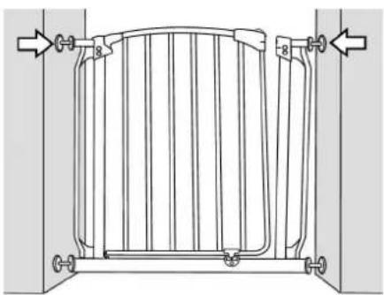
natural_image
Technical line drawing of a mechanical cage or enclosure with vertical supports and directional arrows (no text or symbols)natural_image
Technical line drawing of a mechanical assembly with vertical supports and a central component (no text or symbols)natural_image
Two vertical metal structures with curved and straight edges, labeled 10 and 11 below (no text or symbols on the structures themselves)- Drzwiczki
natural_image
Technical line drawing of a mechanical component with vertical grooves and mounting brackets (no text or symbols)72.5-83.5cm (28.5-32.8")

natural_image
Pure technical line drawing of a mechanical component without any text, numbers, or symbolsnatural_image
Technical line drawing of a mechanical component with vertical grooves and mounting holes (no text or symbols)90.5-101.5cm (35.6-39.5")
natural_image
Pure technical line drawing of a mechanical bracket or frame structure without any text, numbers, or symbols90.5-101cm (35.6-39.5")

natural_image
Pure architectural line drawing of a symmetrical architectural structure with vertical columns and beams (no text or symbols)99.5-110.5cm (39.2-33.5")
natural_image
Pure architectural line drawing of a symmetrical window or enclosure structure (no text or symbols)108.5-119.5cm (42.7-47")
MONTAŻ
natural_image
Diagram of a vehicle rear panel with vertical stripes and a black X mark on the side (no text or symbols)natural_image
Technical line drawing of a mechanical assembly with two parts, no text or symbols presentnatural_image
Two identical diagrams showing a vertical container with a checkmark and an X symbol, no text or labels present.
natural_image
Simple line drawing of a staircase with a vertical hand holding a checkmark (no text or symbols)natural_image
Simple line drawing of a pulley or wheel component (no text or symbols)natural_image
Technical line drawing of a mechanical assembly with a knob and rotating arrow (no text or symbols)
natural_image
Technical line drawing of a mechanical component with vertical bars and mounting flanges (no text or symbols)
natural_image
Technical line drawing of a mechanical or structural component with vertical bars and mounting holes (no text or symbols)natural_image
Technical line drawing of a mechanical assembly with vertical supports and a central bracket (no text or symbols)Read the operating instructions carefully before use.
Save them for future reference.
WARNING:
- Mount and use the gate in accordance with these instructions, otherwise there is a risk of serious and/or fatal personal injury.
- Incorrect mounting or positioning can result in a risk of serious personal and/or fatal injury.
- Risk of personal and/or fatal injury if children use or climb on the gate.
- The gate is intended for children of up to 24 months.
- Never leave children unattended – the product cannot prevent all conceivable accidents. The gate is not a substitute for supervision.
- Never use the gate for children who can open or climb over the gate.
- The surfaces where the gate is fastened must be suitable for the purpose, and must withstand the actual load. NOTE: Do not use the gate if it cannot be mounted flush and firmly to the supporting surfaces (walls, door frames etc.).
- Do not mount the gate over window openings.
- Never use the gate unless it is fixed to the wall with screws.
- Mount the gate at a safe distance from sources of heat.
-
The positioning of the gate in relation to the stairs affects the safety function.
-
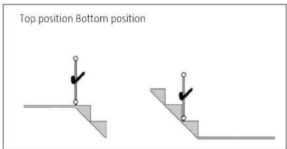
If the gate is used at the bottom of the stairs to prevent children from climbing up it should be placed on the bottom step.
-
If the gate is used at the top of the stairs to prevent children from falling down it should be placed lower than the floor above the stairs.
-
The gate is only intended for private use.
- The gate must be mounted in accordance with these instructions to ensure safe use.
- Check at regular intervals that the gate is correctly and safely mounted in accordance with these instructions. Adjust if necessary.
- Check at regular intervals that the tensioners and the screwed wall brackets are holding the gate firmly in place.
- Do not use the product if any parts are damaged or missing.
• The gate complies with the requirements in the following standard: EN1930:2011 - Only use spare parts and accessories approved by the manufacturer.
DESCRIPTION
GATE AND GATE EXTENSIONS
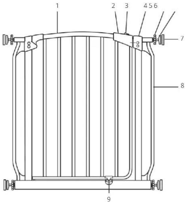

natural_image
Pure diagram of two vertical cylindrical structures with labeled ends (10 and 11), no text or symbols present.- Gate leaf
- Top lock
- Catch
- Top right corner piece
- Tensioner
- Pins with rubber pad
- Bracket
- Gate frame
-
Bottom lock
-
Accessory: Gate extension 18 cm
- Accessory: Gate extension 9 cm
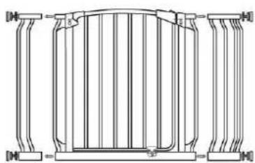
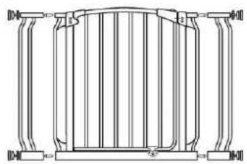
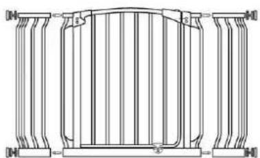
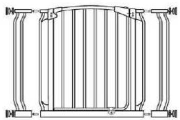
EXAMPLE OF POSSIBLE COMBINATIONS

natural_image
Technical line drawing of a mechanical component with vertical grooves and mounting brackets (no text or symbols)72.5-83.5cm (28.5-32.8")

natural_image
Pure technical line drawing of a mechanical component without any text, numbers, or symbolsnatural_image
Technical line drawing of a mechanical component with vertical grooves and mounting holes (no text or symbols)90.5-101.5cm (35.6-39.5")
natural_image
Pure technical line drawing of a mechanical component without any text, numbers, or symbols90.5-101cm (35.6-39.5")

natural_image
Pure architectural line drawing of a symmetrical architectural structure with vertical columns and beams (no text or symbols)99.5-110.5cm (39.2-33.5")

natural_image
Pure architectural line drawing of a symmetrical window or enclosure structure (no text or symbols)108.5-119.5cm (42.7-47")
MOUNTING
WARNING: The gate brackets must be screwed to the wall. Use screws suitable for the wall material (sold separately).
NOTE: No more than 2 gate extensions can be used, one on each side of the gate. Do NOT mount 2 gate extensions on the same side of the gate.
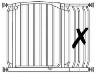
natural_image
Diagram of a vehicle rear panel with vertical stripes and a black X mark on the side (no text or symbols)-
Measure the width of the opening where the gate is to be mounted. The gate fits in openings from 72.5 to 83.5 cm. NOTE: For openings wider than 83.5 cm, select a suitable gate extension.
-
For mounting with gate extension:
— Insert the extension pins in the holes on the outside of the gate frame. Put the long end of the pin in the gate frame. The short end of the pin is put in the long part of the extension frame.
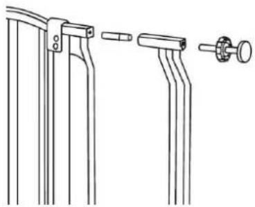
natural_image
Technical line drawing of a mechanical assembly with no visible text or symbols-
Place the gate in the opening with the bottom edge resting flush with the floor.
-
Check that the bottom edge of the gate frame is resting flush with the floor.
- Make sure the gate is at right angles to the wall and floor.

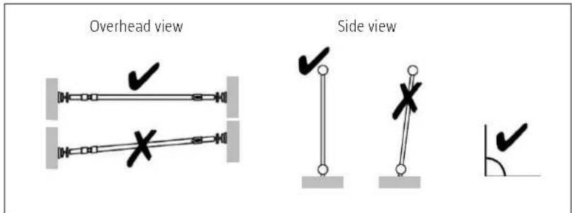
- If the gate is used at the top of the stairs to prevent children from falling down it should be placed lower than the floor above the stairs.
- If the gate is used at the bottom of the stairs to prevent children from climbing up it should be placed in front of the bottom step.
EN
- Mark out the attachment points and pre-drill if necessary. Screw the brackets on the walls with suitable screws for the wall material.
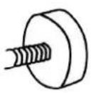

- Put the pins in the attachment points and tighten the tensioners clockwise. Tighten both tensions on each side of the gate at the same time.
NOTE: The gap between the gate frame and gate leaf disappears after the tensioners are correctly adjusted.

natural_image
Technical line drawing of a mechanical assembly with a gear and nut (no text or symbols)
natural_image
Technical line drawing of a mechanical component with internal vertical bars and mounting holes (no text or symbols)
natural_image
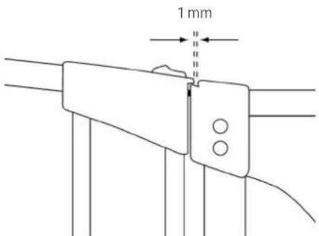
Technical line drawing of a mechanical or architectural component with vertical bars and mounting feet (no text or symbols)- Tighten the tensioners until the top lock and the top right corner piece are in line. The gap between the top lock and the top right corner piece should be 1 mm.
- Centre the gate in the opening. The gap between the walls and tensioners at the bottom of the gate should be the same on both sides.

natural_image
Technical line drawing of a mechanical assembly with vertical rods and a central bracket (no text or symbols)- Check that the gate is firmly attached at the top and bottom.
USE
- Open the gate by pushing the catches to the side. Lift up the gate leaf. The gate can be opened both ways.

-
Close gate by releasing it – it closes automatically. Check the closing function several times and check the following points.
-
The top lock pin and catch engage with the holder in the top right corner piece.
- The bottom lock pin on the gate leaf engages with the holder in the gate frame.
– The tensioners are brackets are firmly attached to the walls.

MAINTENANCE
- Clean by wiping the surface with a cloth or sponge moistened with water and a mild detergent. Never use abrasive, ammonia based or alcohol based detergents.
- If the gate is not secure or does not close properly this is probably because it is not mounted properly. Remove the gate and refit it. Check to make sure the gate has been mounted vertically.
Brand : Hard Head
Model : 660-043
Category : Child safety gate