
PCC Premier - Joystick Vaddio - Free user manual and instructions
Find the device manual for free PCC Premier Vaddio in PDF.


| Product Type | Precision PTZ Camera Controller with Joystick |
| Brand | Vaddio |
| Model | PCC Premier |
| Dimensions (W x D x H) | 17 x 11 x 5.125 inches (43.2 x 27.9 x 12.6 cm) |
| Weight | 7.0 lb (3.18 kg) |
| Power Input | PoE+ (Power over Ethernet), <25W |
| Camera Control Capacity | Up to 16 PTZ cameras (8 via RS-232, up to 80 via IP in 10 groups) |
| Joystick | 3-axis Hall effect joystick with pan, tilt, and zoom (twist) |
| Display | 7-inch capacitive touch panel |
| Control Knobs | Illuminated focus knob (push for auto/manual), menu knob with push-to-select, pan/tilt/zoom speed knobs |
| Camera Select Buttons | 8 illuminated pushbuttons for Control A and Control B buses |
| Video Output | HDMI with H.264 decoder (up to 1080p/60) |
| Connectivity | Gigabit Ethernet with PoE+, 8x RS-232 on RJ-45, HDMI output |
| Web Interface | Full administrative control via browser (Chrome, Firefox, IE, Safari, Edge) |
| Telnet API | Text-based command interface for external control (port 23) |
| Address Book | Up to 11 groups (10 IP/RS-232 mix, 1 RS-232 only) |
| Presets and CCU Scenes | Store/recall presets (up to 16 per camera) and CCU scenes (custom A, B, C) |
| Operating Temperature | 0 to 40°C (32 to 104°F) |
| Storage Temperature | -5 to 60°C (23 to 140°F) |
| Humidity | 20% to 80% RH (non-condensing) |
| Compliance | FCC Part 15 Class A, ICES-003 Class A, CE, RoHS |
| Cleaning and Maintenance | Wipe with clean, soft cloth; no abrasive cleaners; indoor use only |
Frequently Asked Questions - PCC Premier Vaddio
User questions about PCC Premier Vaddio
0 question about this device. Answer the ones you know or ask your own.
Ask a new question about this device
Download the instructions for your Joystick in PDF format for free! Find your manual PCC Premier - Vaddio and take your electronic device back in hand. On this page are published all the documents necessary for the use of your device. PCC Premier by Vaddio.
USER MANUAL PCC Premier Vaddio

natural_image
Three black Vaddi-branded digital camera devices with control knobs and ports, displayed against a blue background (no visible text or symbols on the devices themselves)Integrator's Complete Guide to
PCC Premier
Precision Camera Controller
Document 342-1135 Rev C
Contents
About this Guide..1....
Product Overview 2
Features .2
Product Compatibility...3....
Vaddio Cameras..3....
Non-Vaddio Cameras..3....
Installation 4.
Don't Void Your Warranty!...4.
Unpacking the Camera Controller 4.
Connector Panel 5
Cabling Notes..5....
RS-232 Serial Communication Settings and Port...Pin-out.... 5
Connecting the Controller.... 6
Camera Controller Basics 7
Powering Up the Cameras and Controller 7
Control Console Features.... 7
Touch-Panel Display 7
Focus Knob....7
Menu Knob....7
Camera Select Buttons.... 7
Joystick 8
Pan, Tilt, and Zoom Speed Controls....8
Ensuring Compatibility.... 8
Indicator Lights Cheat Sheet 9
Camera Controller Indicators 9
Power Injector Indicator.... 10
Camera Indicators.... 10
Touch-Panel Display Tour 10
Web Interface.... 13
Compatible Web Browsers 13
Opening the web interface.... 14
A Quick Tour of the Web .Interface.... 15
Address Book 15
PCC Settings.... 16
Room Labels.... 17
Networking 17
Security 18
Diagnostics 18
System 19
Help 19
Working with the Camera Controller 20
Touch-Panel Display Cheat Sheet 20
Web Interface Cheat Sheet 20
Setting up the Address .Book .21.
Selecting Camera Groups to Control 23
Selecting Camera Groups from the Touch-Panel Display 23
Selecting Camera Groups from the Web . Interface . 24.
Working with Lighting and Color Settings 24
Selecting Lighting and Color Settings 24
Adjusting Lighting and Color (CCU) Settings 25
Saving Lighting and Color Adjustments 27
Working with Camera Presets 28
Setting Camera Controller Behavior 29
Standby Settings 29
Mute Settings 30
Video Output Port and Picture_Mode 30
Joystick Settings 30
Powering Down and Returning from Standby 30
Rebooting the Camera Controller 32
Device Administration 33
Renaming Cameras and Camera Groups 33
Adding Room Information 35
Configuring the Camera Controller for Your Network 36
Setting Date and Time 37
Changing the Admin Password 38
Managing Web Interface Sessions 38
Backing Up or Copying a Configuration: Exporting...Data 39
Restoring Factory Defaults 39
Importing Configuration Data 40
Updating the Firmware 40
Downloading the Diagnostic Log 41
Telnet Command API 42
camera focus 43
camera home 43
camera pan 44
camera tilt 44
camera zoom 45
video mute pattern 45
network ping 46
network settings get 46
streaming info dump 47
system standby 48
system reboot 48
system factory-reset 49
sleep .49
help 49
history .50
version .50
exit .50
Specifications .51
Troubleshooting and Care 52
Operation, Storage, and Care 53
Compliance Statements and Declarations of Conformity 54
FCC Part 15 Compliance 54
ICES-003 Compliance 54
European Compliance 55
Warranty Information 56
Index 57
About this Guide
This guide provides information about the PCQprecision camera controller:
■ PCC Premier, North America – part number 999-5750-000
■ PCC Premier, international – part number 999-5750-001
This guide covers
■ Unpacking and installing the camera controller
■ The camera controller's physical features and user interfaces
■ Basic tasks
■ Administration tasks
■ Telnet commands
■ Specifications
■ Troubleshooting and maintenance
■ Warranty and compliance/conformity information
For your convenience, some of this information is also available in the Installation Guide for PCC
Premier Precision Camera Controller, which is limited to unpacking, physical features, installation, and initial power-up.
Download manuals, dimensional drawings, and other information from www.vaddio.com/support.
Product Overview
The Vaddio PCC Premier precision camera controller brings PTZ camera control to the network while maintaining the demanding precision control needed for production environments. The PCC Premier eliminates the need to be in the room with the cameras, making it ideal for live production events, remote studios, and campus network operations centers (NOCs).
Precision control for up to 16 PTZ cameras at once, including up to 8 connected locally via RS-232. Instantly access all PTZ camera related functions ranging from
image settings to presets to dynamic positioning from a single device. Use the integrated H.264 view the live IP stream from the currently selected IP camera from the courtesy HDMI output.

Features
Full control of up to 16 PTZ cameras (2 groups of 8 each) at a time:
■ Up to 8 PTZ cameras via wired RS-232 connection
■ Virtually connect up to 16 RoboSHOT or ClearSHOT cameras at a time, anywhere on the IP network
■ Vaddio's CCU scene macros and full preset store/recall functions
■ Internal H.264 decoder and courtesy HDMI output to monitor the IP stream of the selected remote camera
Precision controls for the most demanding camera operation environments:
■ Three-axis Hall effect joystick
■ Pan, tilt, and zoom speed control knobs
■ Illuminated pushbuttons for camera selection
■ Large knobs for fine focus control and menu navigation, with push-to-select function
Intuitive camera access and addressing through powerful console and web interfaces:
■ Full camera image controls via easy-to-read 7 in. touch-panel interface
■ Web interface for complete administrative control from anywhere, using your browser
■ Store up to 11 camera groups in the Address Book - 10 IP and/or RS-232 control, plus one predefined RS-232-only group
■ Individual control of all cameras in any two camera groups for immediate control of up to 16 cameras at a time
Versatile power solution using PoE+ (Power over Ethernet)
Product Compatibility
The PCC Premier is compatible with the following products.
Vaddio Cameras
| Product RS-232 IP | ||
| RoboSHOT 12/30(may use Quick-Connect) | Yes Yes* | |
| RoboSHOT 12 USB Yes Yes* | ||
| RoboSHOT 12/30 HDMI Yes Yes* | ||
| RoboSHOT 12/30 HD-SDI Yes Yes* | ||
| ClearSHOT 10 USB Yes Yes | ||
| ClearVIEW HD 20SE Yes No | ||
| PowerVIEW HD 22/30 Yes No | ||
| ZoomSHOT 20 Yes No | ||
| WideSHOT Yes No |
* The PCC Premier can control RoboSHOT cameras via the IP network only if the cameras use 2.0.0 or newer firmware. Control via IP uses the camera's IP address, not the address of its C or OneLINK device.
Non-Vaddio Cameras
| Product RS-232 IP | ||
| Sony BRC Z 330 | Yes No | |
| Sony BRC Z 700 | Yes No | |
| Sony BRC H 700 | Yes No | |
| Sony BRC H 900 | Yes No | |
| Sony EVI-H100S | Yes No | |
| Sony SRG 120 | Yes No | |
| Sony SRG 300 | Yes No | |
| Panasonic AW-HE 40 | Yes No | |
| Panasonic AW-HE 130 | Yes No |
Installation
This section covers how to install and connect the controller. It also provides safety information a guidance related to installing the controller.
Don't Void Your Warranty!
Caution
This product is for indoor use. Do not install it outdoors or in a humid environment without the protective enclosure. Do not allow it to come into contact with any liquid.
Do not install or operate this product if it has been dropped, damaged, or exposed to liquids. It is things happen, return it to Vaddio for safety and functional testing.
Learn more at www.vaddio.com/products.
Unpacking the Camera Controller
Make sure you received all the items you expected. Here are the packing lists for the PCC Pr controller.
North America: PCC Premier, part number 999-5750-000
■ PCC Premier, part number 998-5750-000
■ Mid-span power injector with US cord set, part 0800-055
■ Cat-5e patch cable, 10 ft (3 m), part number
■ Quick Start Guide, part number 342-1134
International: PCC Premier, part number 999-5750-001
■ PCC Premier, part number 998-5750-000
■ Mid-span power injector with UK and European part number 451-0800-155
■ Cat-5e patch cable, 10 ft (3 m), part number
■ Quick Start Guide, part number 342-1134


Connector Panel

From left to right:
Ethernet/PoE+ connector – PoE+ Gigabit Ethernet port provides access to the controller's web interface and to cameras on the network, and powers the controller.
HDMI connector – Monitor the camera you are currently controlling. Video can only be displayed for cameras with IP streaming capability.
RS-232 ports - Connect up to 8 cameras locally.
Cabling Notes
RS-232 cables may be up to 500 ft (152.4 m).
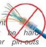
For RS-232 cabling, use Cat-5e or better cable and standard RJ-45 connectors (568B termination). We recommend using high-quality connectors and a high-quality crimping tool.
Note
Do not use pass-through RJ-45 connectors. These can cause intermittent connections and degraded signal quality, resulting in problems that may be hard to diagnose. Use standard RJ-45 connectors and test all cables for proper pin-outs and continuity before you connect them to Vaddio products.
RS-232 Serial Communication Settings and Port Pin-out
The RS-232 serial ports (color-coded blue) on the PCC Premier back panel allow you to connect cameras directly.
RS-232 communication parameters are as follows:
| Parameter Value | |
| Communication Speed 9600 bps (default) | |
| Start bits 1 | |
| Stop bits 1 | |
| Data bits 8 | |
| Parity None | |
| Flow control None | |
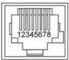
Connector pin-out:
■ Pin 1: Not used
■ Pin 2: Not used
■ Pin 3: Not used
■ Pin 4: Not used
■ Pin 5: Not used
■ Pin 6: GND
■ Pin 7: TXD (to RXD of camera)
■ Pin 8: RXD (from TXD of camera)
Caution:
Check Cat-5 cables for continuity before using them. Using the wrong pin-out may damage the c system and void the warranty. Pro tip: Label your cables.
Connecting the Controller
Set up all cameras and make all physical connections first. You will be able to add network-con cameras after the cameras and controller are fully operational.
In this example, cameras are directly connected to the RS-232 ports, and the controller is set up several address book groups of cameras remotely via the IP network. A display connected to the HDMI port allows the operator to monitor the camera currently selected, if it is an IP streaming mid-span power injector provides power and network connectivity.

flowchart
graph TD
    A["Power"] --> B["Network"]
    C["PoE+"] --> B
    D["IP Network"] --> B
    E["RS-232"] --> B
    F["Video"] --> B
    G["Address Book group (1 - 8 cameras)"] --> B
    H["0...10"] --> I["Data In"]
    I --> J["Data & Power Out"]
    J --> K["Network Port"]
    K --> L["KB-232 CAMERA CONTROL PORTS"]
    L --> M["10101"]
    M --> N["10101"]
    N --> O["10101"]
    O --> P["10101"]
    P --> Q["10101"]
Camera Controller Basics
This section covers powering the camera controller and making sure it is able to communicate w cameras. It also includes a quick tour of the console and information on accessing the controller's interface.
Powering Up the Cameras and Controller
Power up all cameras to be used with the controller.
When you connect the PCC Premier to the network for the first time, it will only identify support that are directly connected via RS-232. After the Address Book has been set up, the controller establish contact with all IP-connected cameras in its address book when it powers up.
Control Console Features
The console provides basic address book and other functions in addition to camera control.
Touch-Panel Display
The touch-panel provides:
■ Access to the address book, to set up and select camera groups
■ Access to camera presets and CCU scenes
■ CCU and CCU scene setup
■ Network information for the controller
■ One-touch standby (controller and selected cameras)

Focus Knob
Press the focus knob to switch between modes - auto-focus (illuminated blue) or manual (illumina In manual focus mode, turn the knob to adjust the focus.
Menu Knob
This knob provides precision in setting slider controls. Dial to the desired setting, then press the to save it.
You can also use the Menu knob to navigate the touch-panel screens and some of the controls
Camera Select Buttons
The camera select buttons allow you to select the camera to work with, from the two active ca (Control A and Control B). During normal operation, the buttons are illuminated if they are mapped cameras in the active groups. If a button is not lit, it means one of these things:
■ No camera is connected to the RS-232 port assigned to this button.
■ No IP-connected camera has been assigned to this button.
Joystick
The joystick provides intuitive control for moving the selected camera to the desired position - left pan, forward/back to tilt. Twist the joystick clockwise or counterclockwise to zoom the camera. Pre center button to return the camera to its home position. The camera controller's web interface all set normal or inverted directional operation, according to the operator's preference.
Pan, Tilt, and Zoom Speed Controls
The three speed control knobs above the joystick allow you to adjust the selected camera's spee tilt, and zoom. When you adjust any of these knobs, the touch-panel displays a slider to show range.
Ensuring Compatibility
The camera controller may be unable to communicate with its Vaddio cameras if their firmware is date. When you set up the camera controller, be sure its Vaddio cameras have been updated to 2.0.0 firmware or later. This keeps them playing nicely together.
Indicator Lights Cheat Sheet
Whenever the components of your system don't do what you expect, check the indicator lights for Camera Controller Indicators
| Location State Meaning | ||
| Touch-panel virtual indicator: Camera streaming status (indicator in upper right corner) | black The selected | ed camera is not available. It may be disconnected, rebooting, or updating firmware. |
| blue The selected | d camera is connected but not streaming to the camera controller. This may mean:■ The camera does not have IP streaming capability■ The camera's IP stream is not enabled■ The camera is connected via RS-232 | |
| yellow (momentary) | ) The HDMI output stream has paused. This happens when you select a different camera. When the change in selection is complete, the indicator changes to show the newly selected camera's state. | |
| green The selected | ed camera's stream is available on the HDMI output. | |
| Control A and Control B camera buttons | Not illuminated R | RS-232 connected camera is not available (power is disconnected or the camera's firmware is updating)No camera is mapped to the button (for example, the address book group may have fewer than 8 cameras assigned) |
| Blinking blue A | camera is not available at this IP address.This can occur if:■ The camera is present but not available (for example, a firmware update may be in progress or its power may be disconnected)■ The camera is present but its standby state is out of sync with the controller (for example, someone placed the camera in standby using its own web UI or remote)■ The device at this IP address is not a compatible camera■ There is no device at this IP address. | |
| Blue | Camera is available | |
| Red Camera is | selected | |
| Focus knob | Not illuminated | The current camera selection is inactive or absent |
| Red The selected | d camera is in manual focus mode | |
| Blue | The selected camera is in auto focus mode. | |
| Menu knob | Blue | Normal operation - able to navigate the touch-panel |
| Network and PoE Blinking port | Not illuminated | Normal operation - receiving power and connected network |
| ■ The power injector is not connected to the network (Data In connection)■ The camera controller is not receiving power. | ||
Power Injector Indicator
| State Meaning | |
| Illuminated orange | Power connection is good. No connection from the Data and Po to the camera controller. |
| Illuminated green | The power connection is good, and the connection from the Data connector to the camera controller is good. |
Note
The indicator light does not provide information about the connection from the Data In connector network.
Camera Indicators
Indicator light codes vary among models of cameras. Consult the camera documentation.
Touch-Panel Display Tour
The area at the top of each screen shows information about the currently selected camera.

Home screen – Choose the screen you need to see, or put the camera controller in standby. When you tap the Power button, the camera controller presents a confirmation message. When you to go ahead with the standby operation, the cameras in the currently selected groups may also standby mode. This is configurable in the camera controller's web interface. See Setting Camera Controller
Behavior.
Cameras in groups that are not currently selected remain in their current state.

Presets screen – Work with the selected camera's presets. The camera controller does not store presets internally. It accesses the presets stored in the currently selected camera, and can write presets camera.
Note
For some older Vaddio cameras, presets may be unavailable to the camera controller if they were the IR remote.
Presets may include lighting and color adjustments. See Working with Lighting and Color Settings for information on making these adjustments.
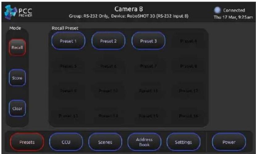
CCU screen – Adjust lighting and color (CCU) settings and store adjustments as CCU scenes. S Working with Lighting and Color Settings for more information.

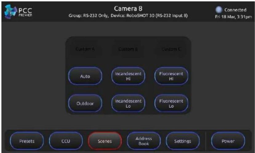
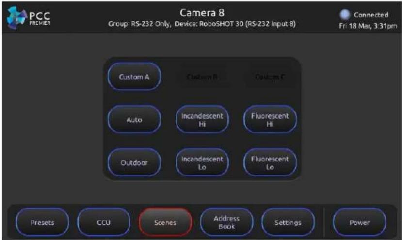
Scenes screen – Choose lighting and color adjustments (CCU scenes) defined for the selected camera.
Address Book screen – Choose the camera groups to control with the Control A and Control B camera select buttons. See Selecting Camera Groups to Control for more information.

Settings screen – View firmware and network information for the camera controller, and set the brightness for the touch-panel display.

Web Interface
The camera controller provides a web interface to allow configuration via the IP network connection a browser. The web interface allows you to:
■ Manage network settings
■ Set up the camera controller's address book
■ Specify how the joystick behaves
■ Add identifying information to the camera controller's web interface
■ Set the password and idle session behavior for the camera controller
■ Back up, reboot, reset, or update the camera controller
■ View information about the camera controller
If a DHCP server is available, the controller will get its IP address, gateway and routing informa automatically.
Compatible Web Browsers
Supported web browsers:
Chrome®
■ Firefox®
■ Microsoft® Internet Explorer®
■ Safari®
■ Microsoft® Edge
Other browsers may also work.
Opening the web interface
- Locate the camera controller's IP address on the touch-panel display. This information is on the Settings screen. If you know the camera controller's hostname, you can use that instead.
- Enter the camera controller's IP address or hostname in your browser's address bar If you use the hostname, you may need to enter http:// as a prefix to keep the browser from treating it as a search query.
- Log in for access to the administrative controls. The username is admin and the default password is password.

A Quick Tour of the Web Interface
This covers what you can do on each page.
Address Book
Things you can do on this page:
■ Add or delete IP-connected cameras – see Setting Up the Address Book
■ Rename cameras
■ Create, edit, rename, or delete camera groups – see Setting Up the Address Book
- Select the camera groups to map to the Control A and Control B buttons - see Selecting Camera Groups to Control
■ Rename camera presets and CCU scene labels

PCC Settings
Things you can do on this page:
■ Put the camera controller in standby mode
■ Specify whether the cameras currently mapped to the camera select buttons also go to standby
■ Specify the pattern on the HDMI output when a streaming camera is not selected
■ Set the HDMI output resolution and color space
■ Adjust the contrast and brightness on the display connected to the HDMI output
■ Specify how the joystick behaves

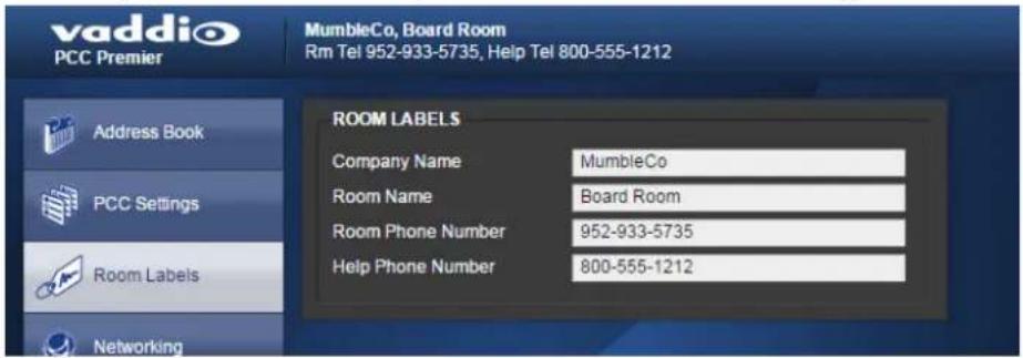
Room Labels
On this page, you can set the camera controller's web interface to display:
■ The name of your organization
■ The name and phone number of the room where the camera controller is installed
■ The phone number for your in-house A/V or IT support
Networking
Things you can do on this page:
■ Set the camera controller to use an NTP server for time and date, and specify the time zone to use
- Assign the camera controller's hostname
■ Specify DHCP or static IP addressing
■ Set up IP address, subnet mask, and gateway address if static addressing is selected

Security
Things you can do on this page:
- Set idle web interface sessions to time out – if the check box is checked, users are logged out of the web interface after 30 minutes of inactivity.
■ Change the admin password for the web interface.

Diagnostics
Things you can do on this page:
■ View and download the diagnostic log
■ Clear the display area
■ Restore the log information that you cleared
![vaddio PCC Premier MumbleCo, Board Room Rim Tel 952-933-5735, Help Tel 800-555-1212 Address Book PCC Settings Room Labels Networking Security Diagnostics System Help Logout DIAGNOSTICS Jan 6 11:03:00 vaddio-plutus [ 1.038261] TCP: cubic registered Jan 6 11:03:00 vaddio-plutus [ 1.041662] Initializing XFRM netlink socket Jan 6 11:03:00 vaddio-plutus [ 1.046128] mmc0 new high speed SD card at address b368 Jan 6 11:03:00 vaddio-plutus [ 1.051580] NET: Registered protocol family 17 Jan 6 11:03:00 vaddio-plutus [ 1.056118] 802 to 802 1Q VLAN Supportv1.8 Jan 6 11:03:00 vaddio-plutus [ 1.060268] mmcbki3: mmc0 b368 962 MiB Jan 6 11:03:00 vaddio-plutus [ 1.064766] Registering SWPSWPS emulation handler Jan 6 11:03:00 vaddio-plutus [ 1.070749] regulator-dummy: disabling Jan 6 11:03:00 vaddio-plutus [ 1.072710] mmcbki0: c1 p2 p3 p4 < p5 p6 p7 p8 > Jan 6 11:03:00 vaddio-plutus [ 1.085678] input button_bus_a.15 as /devices/button_bus_a.15/input/input5 Jan 6 11:03:00 vaddio-plutus [ 1.094774] input button_bus_b.15 as /devices/button_bus_b.16/input/input5 Jan 6 11:03:00 vaddio-plutus [ 1.102585] input button_menu_17 as /devices/button_menu_17/inputinput7 Jan 6 11:03:00 vaddio-plutus [ 1.110103] input button_focus_18 as /devices/button_focus_18/inputinput8 Jan 6 11:03:00 vaddio-plutus [ 1.125632] VFS: Mounted root (xtr4 filesystem) readonly on device 179.3. Jan 6 11:03:00 vaddio-plutus [ 1.133741] devtrnpts: mounted Jan 6 11:03:00 vaddio-plutus [ 1.136813] Flesing unused kernel memory: 168K (c047f000 - c04a900) Jan 6 11:03:00 vaddio-plutus [ 2.077875] atmel_mxt_is_0-004c Family: 161 Variant 2 Firmware V2.0.AA Objects: 23 Jan 6 11:03:00 vaddio-plutus [ 2.086665] Input Atmel maxTouch Touchscreen as /devices/ramba.0/e9004f000 ps7-2c/2c-0/0-0f4c/input/input9 Jan 6 11:03:00 vaddio-plutus [ 2.10446C] Loading module zyng joystick Jan 6 11:03:00 vaddio-plutus [ 2.108572] js_parse_dlti of_property samples per second 40 Jan 6 11:03:00 vaddio-plutus [ 2.114065] js_parse_dlti iio_chan_names[3] VauxO Jan 6 11:03:00 vaddio-plutus [ 2.119034] js_parse_dlti iio_chan_names[1] VauxI Jan 6 11:03:00 vaddio-plutus [ 2.123783] js_parse_dlti iio_chan_names[2] Vaux2 Jan 6 11:03:00 vaddio-plutus [ 2.128584] js_parse_dlti iio_chan_names[3] VauxS Jan 6 11:03:00 vaddio-plutus [ 2.133345] js_parse_dlti Button name Joystick-bn Jan 6 11:03:00 vaddio-plutus [ 2.139158] input Zyng Joystick as /devices/virtual/inputinput10 Jan 6 11:03:00 vaddio-plutus [ 2.90226C] random: old urandom read with 61 bits of entropy available Jan 6 11:03:03 vaddio-plutus [ 6.562214] random: nonblocking pool is initialized Jan 6 11:03:09 vaddio-plutus [ 12.419533] xemacps e90b9c9b ps7-ethernet Set clk to 24999999 Hz Jan 6 11:03:09 vaddio-plutus [ 12.425927] xemacps e90b9c9b ps7-ethernet link up (169/FULL) Download Refresh Clear Restore](/content/2026/05/867461/images/80c13e62ff3f6d73813422484245b5c7789b594c7a0c2620672f399141cec3ce.jpg)
System
Things you can do on this page:
■ Reboot the camera controller
■ Back up (export) or restore (import) configuration data
■ Set the camera controller back to its original factory settings
■ Update the firmware
All these operations except exporting data will require you to log in again afterward.

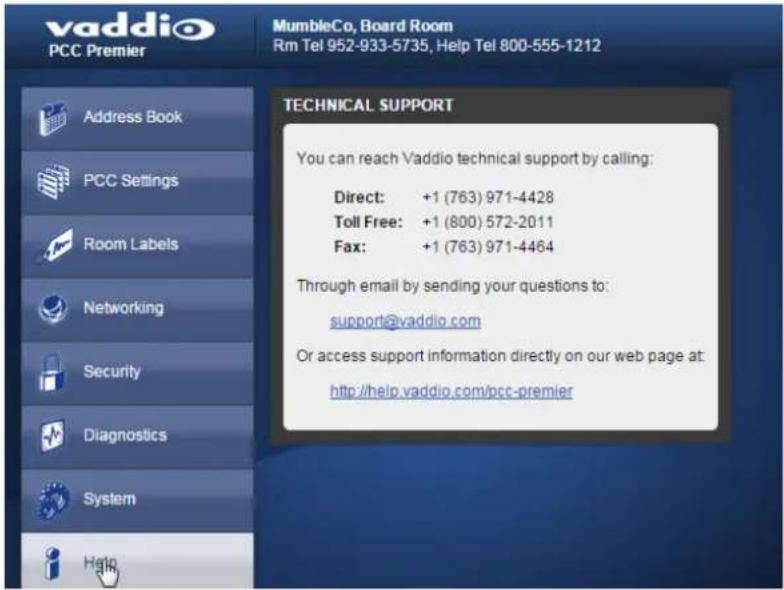
Help
If you can't resolve an issue on your own (see the Troubleshooting table in this manual), we are here to help. You'll find information for contacting Vaddio Technical Support on the Help page.
Working with the Camera Controller
You have the PCC Premier camera controller installed and powered up. You've read Controller Basics, so you know where the controls are and what they do. Now you're ready to start using it.
Touch-Panel Display Cheat Sheet
Where to find the camera and system controls you need right now.
| What do you need? Go to this | screen |
| System IP address and other network information Settings | |
| Manage Control Bus A and Control Bus B Address Book | |
| Store or recall presets for the selected camera Presets | |
| Select a defined set of lighting and color adjustments (see call a CCU scene) for the selected camera | |
| Adjust color and lighting settings for the selected camera CCU | |
| Store your color and lighting adjustments as a CCU (see store as scene the selected camera | |
| Adjust the touch-panel's brightness Settings: LCD Brightness | |
| Put the system into standby mode (may also put mapped to Control A and Control B buttons into this is configurable) | Prevecameras standby mode; |
Web Interface Cheat Sheet
Where to find the controls you need right now.
| What do you need? Go to this page | |
| Camera controller hostname and network settings | Networking |
| Cameras and camera groups | Address Book |
| Camera controller behavior | PCC Settings |
| Settings for HDMI output | PCC Settings |
| Password for admin account | Security |
| Information about the camera controller's location | Room Labels |
| Backup and restore operations | System |
| Firmware update and current version | System |
| Time and date settings | Networking |
| Reboot or factory reset | System |
| Helpdesk phone number for end users | Room Labels |
| Contact information for Vaddio helpdesk | Help |
| Diagnostic log | Diagnostics |
| Session timeout | Security |
| Standby | PCC Settings |
Setting up the Address Book
Web interface, Address Book page
Cameras are available if they are in the camera controller's address book.
Log in to the camera controller's web interface to set up the address book.
The PCC Premier organizes cameras into groups, and allows you to work with two groups at a predefined RS-232 group contains all cameras connected directly via RS-232. You can add other which you may define as RS-232 only or IP and RS-232. Cameras may belong to more than each, so you can organize the cameras in the way that works best for you.
Note
The PCC Premier camera controller may be unable to communicate with its cameras if their firm of date. When you set up the camera controller, be sure its Vaddio cameras have been updated 2.0.0 firmware or later.
When you power the camera controller, it auto-detects the cameras connected via RS-232 if they to communicate. You do not need to do any setup for RS-232 connected cameras. If Vaddio can not be detected, update their firmware to the latest version available under Software Updates on Vaddio's
support page.
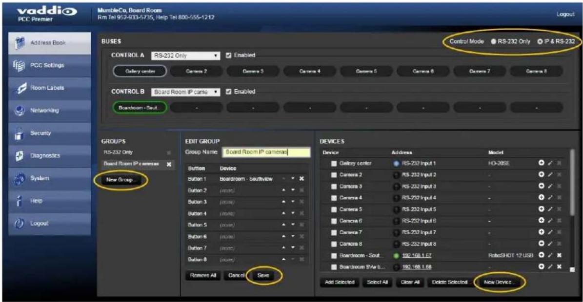
The general process for setting up the address book is:
Define at least one group.
- Under Groups, click New Group.
- In the Add New Group box, give the group a name and save it. The new group appears groups.
- Under Groups, click the name of the group you just created. Its name appears in the Edit
- In the upper right part of the page, set the Control Mode to IP & RS-232.
Collect the hostnames or IP addresses of the cameras to be added to the Address Book.
You may wish to add IP-connected cameras using their hostnames rather than their IP addresses. way, the camera controller automatically locates and connects to the camera even if the camera's address changes - for example, if you move it to a different room.
If you don't have a list of hostnames or camera IP control addresses – the addresses for the internally served web interface pages – you can get any Vaddio camera's IP control address usir remote. Press the Data Screen button to display this.
Add the cameras.
- Under Devices, click New Device.
- In the Add New Device box, enter the camera's IP control address, give it a device label,
- Repeat this until you have added all the cameras you want to assign.
Assign the cameras to groups.
- Under Groups, click the name of the group you want to populate. Its name appears in the pane.
- Under Devices, locate the name of a camera you want to add to this group. (You can add more than one group.)
-
Do one of these things:
-
Drag a camera name to the desired button in the Edit Group pane, repeating as needed,
-
Check the box to the left of each camera that you want to add to the group, then click to add all of them to the group.
-
Save your changes.
You can now select the defined groups and control the cameras in them from the console.
Selecting Camera Groups to Control
After you have set up the address book, you can select the groups to work with. You can dc the web interface or from the console's touch-panel display.
By default, the buttons on the Control A bus are mapped to the RS-232 cameras. You can ch
Selecting Camera Groups from the Touch-Panel Display
- On the touch-panel display, open the Address Book screen to select camera groups.
- Choose the camera control bus to define - Control A (the top row of buttons) or Control E row) - and tap its control to make it active.
- Tap the group name to open the list of available groups, and tap the name of the group controls become inactive for a few seconds while the camera controller maps control bus butto cameras in the selected group.
- If you need to verify that you have chosen the group you want, tap the Info button. This cameras in the group. Tap the Back button to return to the Address Book screen; or tap the button to go to the Home screen.
-
The camera select buttons on this control bus are now mapped to the cameras in the group selected.
-
Repeat this for the other control bus, if necessary.

Selecting Camera Groups from the Web Interface
- On the Address Book page of the web interface, click the down-arrow in the group name by desired control bus - Control A or Control B. This displays a list of available camera groups.
- Select the group you want.
- Check the Enabled checkbox for this control bus. The buttons show the names of the camera group.

Now you're ready to work with the cameras.
Working with Lighting and Color Settings
The camera controller gives you access to the selected camera's defined lighting and color setting (scenes) and its lighting and color (CCU) adjustments. You don't need to access each camera's interface separately to adjust for consistent video across entire camera groups.
Selecting Lighting and Color Settings
Touch-panel, Scenes screen
If the lighting or color balance doesn't look right in the video from the selected camera, go to screen and choose the appropriate lighting setting. These are good starting points if you are not experienced with lighting and camera painting/shading.

If none of the available scenes produce the desired results, you can create custom settings.
Adjusting Lighting and Color (CCU) Settings
Touch-panel, CCU screen
If none of the lighting selections on the Scenes screen produce the desired results, adjust the in the controls on the CCU screen.

You may need to experiment to find the best combination of image adjustments.
If you are not experienced in this area, here are some tips.
| What do you need to correct? | Change this: How: | ||
| The image is too dark Iris Increase | |||
| Iris Gain Increase | |||
| The image looks washed out or faded | Iris Decrease | ||
| Iris Gain Decrease | |||
| Chroma Increase | |||
| Gamma Decrease | |||
| The subject is silhouetted against a background | Bright Compensation | On | |
| Colors look less vivid than they should chroma Increase | |||
| Colors look too vivid Chroma Decrease | |||
| Highlights and shadows look right, but tones are too dark. | Gamida Increase | ||
| The mid-tones are too light. | Gamma Decrease | ||
| The image looks grainy | Detail | Decrease | |
| Iris Gain Decrease | |||
| "Soft focus" effect; the image looks unrealistically smooth | Detail | Increase | |
| Colors look wrong; white objects do white | Auto appear | On | |
| One Push | (tap) | ||
| Red Gain (less red/less green) | Dial down/up | ||
| Blue gain (less blue/less yellow) | Dial down/up | ||
| Too much red | Not enough red | Too much blue | Not enough blue |
 |  |  |  |
If you are adjusting for lighting conditions that are likely to recur, you can save your adjustment custom scene.
Saving Lighting and Color Adjustments
Touch-panel, CCU screen
When the lighting and color look good, tap Store as Scene to save the adjustments. The screer you to store the scene as Custom A, Custom B, or Custom C.

After you store the scene, it is available on the Scenes screen.
If it is a Vaddio camera, you can rename custom scenes in the camera's web interface.
Working with Camera Presets
Touch-panel, Presets screen
The camera controller does not store presets internally. It accesses the presets stored in the cun selected camera, and can write presets to the camera.
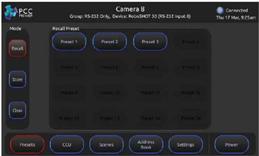
To store a new preset to the selected camera:
- Set up the shot, including all adjustments.
- On the Preset screen, tap Store.
- Tap the preset button to assign. If you choose a preset that is already assigned, you will be existing preset when you save the new one.
- Optional: Tap the Color button or TriSync button (or both) if you want to save them as part
- Tap Save.

When you tap Back to return to the main Recall Preset screen, the new preset is available.
Setting Camera Controller Behavior
Web interface, PCC Settings page
On this page, you can set:
■ What happens when the camera controller goes into standby mode
■ What happens when no video stream is available on the HDMI output
■ HDMI video settings
■ Joystick direction

Standby Settings
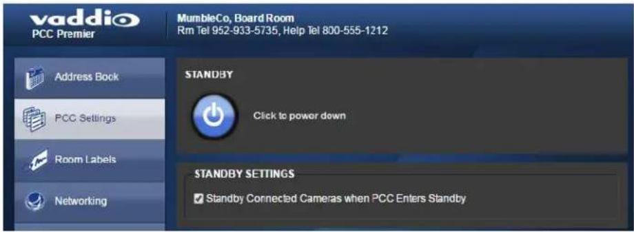
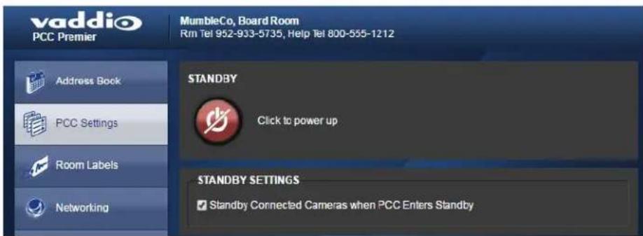
To place the cameras in standby mode along with the camera controller, check the box marked Connected Cameras when PCC Enters Standby."
Note
This setting only applies to the cameras in the groups currently selected as Control A and Cont cameras in the address book are not affected.
Leave this check box unchecked if all cameras should remain powered up when the camera con to standby mode.
Mute Settings
This specifies how the HDMI output behaves when a non-streaming camera is selected, or when camera is selected. If you select a streaming camera that is muted, the HDMI output is that can pattern. For example, the stream from a Vaddio camera in the RoboSHOT series is a blue screw. Select color bars or black.
Video Output Port and Picture Mode
If necessary, change the resolution and color space to suit the capabilities of the display connect HDMI output port.
Note
The H.264 decoder provides a 1080P30 signal. The UI output setting is to configure for your mobile abilities.
You can also adjust the display's brightness and contrast as needed.
Joystick Settings
Select Normal or Inverted for joystick pan and tilt axes.
Powering Down and Returning from Standby
You can do this from the touch-panel display or from the web interface.
Note
Depending on the standby settings configured in the web interface, the cameras currently mapped Control A and Control B buttons may also go to standby mode with the camera controller. Camera groups remain in their normal operating states. See Setting Camera Controller Behavior for more information.
From the touch-panel display:
Tap Power to enter standby mode. You'll get a confirmation prompt.

When the camera controller is in standby, you can tap the touch-panel to return to normal open

From the web interface:
On the PCC Settings page, click Standby. The button and its label show the controller's current what will happen when you click the button.
Rebooting the Camera Controller
Web interface, System page
This can help if the camera controller stops responding as you expect.
In the System Utilities section, click Reboot. Then confirm that you want to reboot. You will nee again after the reboot finishes.
If rebooting the camera controller doesn't fix the problem, you may need to reset to factory defaults. But before you take that step, back up the configuration.

Device Administration
The web interface provides access to all administrative tasks.
Renaming Cameras and Camera Groups
Web interface, Address Book page

To rename a group:
- Click the group name from the Groups list. The Edit Group pane displays the group name a
- In the Group Name box, change the name.

To rename a camera:
- Locate the camera in the Devices list.
- Click the pencil icon associated with that camera.

The Device Settings box opens, allowing you to edit the camera information.

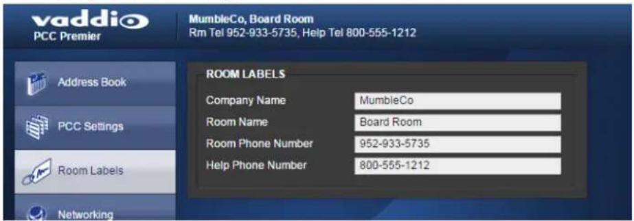
Adding Room Information
Web interface, Room Labels page
Enter information about the location of the equipment and the local IT or A/V help line. This in be displayed on all pages of the web interface.
Configuring the Camera Controller for Your Network
Web interface, Networking page
The camera controller uses DHCP addressing by default. If no DHCP server is available, the def address is 169.254.1.1.
Note
If you don't completely understand all the implications of the steps below, please contact your IT Vaddio Technical Support for assistance.
- Edit the device hostname if necessary. The hostname serves as the device URL, so you can instead of the device's IP address when you open a web interface session. The hostname is as the filename for exported configuration data, so it can help you identify the source of an data file.
- If the camera controller needs to use static IP addressing, select Static.
- For static IP addressing, enter the appropriate IP address, subnet mask, and gateway address.

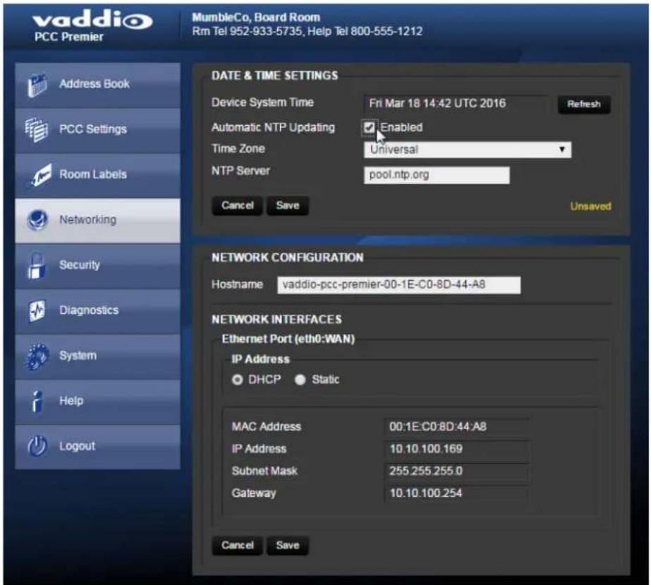
Setting Date and Time
Web interface, Networking page
- To set the camera controller to get date and time from a time server:
- Check the box to enable Automatic NTP Updating.
- Select your time zone from the list.
- Leave the default NTP server information, or change it to the server you want to use.
After you save changes, it may take a few seconds for the system time display to update. Click Refresh button if you're impatient.
Changing the Admin Password
Web interface, Security page
The default password for the admin account is password.
- To change this, click Edit Password.
- In the Edit Password dialog, enter the new password in the two password boxes. A prompt while you type If you don't type it exactly the same way both times.

Managing Web Interface Sessions
Web interface, Security page
For security, users are logged out of the web interface after 30 minutes of inactivity.
To keep inactive sessions from expiring, clear the checkbox labeled Automatically Expire Idle Session. Once you are logged in, your session remains open until you log out or restart your computer.

Backing Up or Copying a Configuration: Exporting Data
Web interface, System page
If your organization uses several PCC Premier camera controllers, you may choose to configure o them, verify that the configuration is good, and then copy it to the camera controllers.
Note
Currently, the camera controller cannot import a .dat file that was exported from a different version software than the controller is on. Example: You cannot currently import a 1.0.0 configuration to a controller, or vice versa.
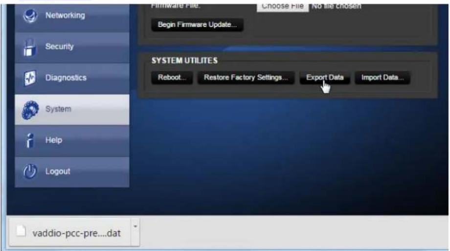
- To save a copy of the camera controller's current configuration, click Export Data. The file dc your default file download location. The filename is the camera controller's hostname followed by .dat file extension. If you only need to back up the configuration, you're done.
- If you need to copy the configuration to other PCC Premier camera controllers, see Importing a Configuration.
Restoring Factory Defaults
Web interface, System page
Restoring factory settings will overwrite anything you have added or customized, such as IP camera address book groups. (If you export a known good configuration from this camera controller or another PCC
Premier, you can import it again after restoring factory settings.)
To restore the original factory settings:
- Click Restore Factory Settings. A confirmation message informs you that the action cannot be This is your cue to make sure you have successfully exported the configuration.
- When you click Continue, the camera controller reboots and the web interface presents a mes the device has been rebooted.
This operation logs you out and resets the admin password to its factory default value of password.
Importing Configuration Data
Web interface, System page
If you have already exported a known good configuration, you can import it back to the camera controller, or copy it to other PCC Premier camera controllers.
Note
Currently, the camera controller cannot import a .dat file that was exported from a different version software than the controller is on. Example: You cannot currently import a 1.0.0 configuration to a controller, or vice versa.
To restore an exported configuration:
- Click Import.
- In the Import box, click Choose File.
- Browse to the .dat file for the PCC Premier and select it.
- Click Begin Importing Data. The Import Data box displays progress messages, the touch-panel displays its reboot sequence, and you get a message that the device has been rebooted.
You will need to log in again after importing the data. You will need to use the admin password to use when the data was exported - it is part of the configuration data.
Updating the Firmware
Web interface, System page
From time to time, we issue new firmware to introduce new features and other product improvement to fix issues that turn up. We recommend keeping all your Vaddio products up to date, to get them.
Firmware updates do not change the camera controller's configuration. When you log in again after update finishes, the password is unchanged.
Note
It is rare for an update to generate errors. If this happens, please read them carefully and receive Screen shots of the error message may be very helpful in troubleshooting the problem. If the up not finish successfully, contact Vaddio technical support immediately.
- In a separate browser tab, go to support.vaddio.com and download the appropriate update file.
- In the Firmware Update pane, click Choose File. Then browse to the update file and select
- Click Begin Firmware Update.
- READ the information in the Confirm dialog box and be sure you understand it.
- When you are ready to start the update, click Continue. The web interface and the touch-par display messages showing that an update is in progress. The camera controller reboots as the in the update process.
We recommend checking for firmware updates for your Vaddio cameras when you update the cam controller firmware.
Downloading the Diagnostic Log
Web interface, Diagnostics page
If you encounter a problem that you can't solve, your Vaddio technical support representative may to email the log file available from the Diagnostics page.
Click the download button. The name of the file will be the camera controller's hostname followed .tar.gz.
![vaddio PCC Premier MumbleCo, Board Room Rm Tel 952-933-5735, Help Tel 800-555-1212 Address Book PCC Settings Room Labels Networking Security Diagnostics System Help Logout DIAGNOSTICS Jan 6 11:03:00 vaddio-plutus [ 1.038261] TCP: cyclic registered Jan 6 11:03:00 vaddio-plutus [ 1.041862] Initializing XFRM netlink socket Jan 6 11:03:00 vaddio-plutus [ 1.048128] mmc0 new high speed SD card at address b368 Jan 6 11:03:00 vaddio-plutus [ 1.051580] NET: Registered protocol family 17 Jan 6 11:03:00 vaddio-plutus [ 1.056118] 802 tq: 802 10 VLAN Support v1.8 Jan 6 11:03:00 vaddio-plutus [ 1.060268] mmc0 b368 962 MB Jan 6 11:03:00 vaddio-plutus [ 1.064766] Registering SWP/SWPB emulation handler Jan 6 11:03:00 vaddio-plutus [ 1.070749] regulator-clummy: disabling Jan 6 11:03:00 vaddio-plutus [ 1.072710] mmc0 p1 p2 p3 p4 < p5 p6 p7 p8 > Jan 6 11:03:00 vaddio-plutus [ 1.085678] input button_bus_a.15 as /devices/button_bus_a.15/input/input5 Jan 6 11:03:00 vaddio-plutus [ 1.094774] input button_bus_b.16 as /devices/button_bus_b.16/inputinput5 Jan 6 11:03:00 vaddio-plutus [ 1.102588] input button_menu_17 as /devices/button_menu_17/inputinput7 Jan 6 11:03:00 vaddio-plutus [ 1.110100] input button_focus_18 as /devices/button_focus_18/input/input8 Jan 6 11:03:00 vaddio-plutus [ 1.125632] VFS: Mounted root (ext4 filesystem) readonly on device 179.3 Jan 6 11:03:00 vaddio-plutus [ 1.133741] devmpcs: mounted Jan 6 11:03:00 vaddio-plutus [ 1.136613] Fleeing unused kernel memory: 168K (cD47B00 - cD4aS00) Jan 6 11:03:00 vaddio-plutus [ 2.077675] ame_lmdt.js_0-004s; Family: 161 Variant 2 Firmware V2.0 AA Objects: 23 Jan 6 11:03:00 vaddio-plutus [ 2.086668] input Atmel maxTouch Touchscreen as /devices/amba 0ie300400 ps7-2c/2c-0/0-0C4c/input/input9 Jan 6 11:03:00 vaddio-plutus [ 2.104460] Loading module zyng joystick Jan 6 11:03:00 vaddio-plutus [ 2.108572] js_parse_dtt): cf_procery; samples per second 40 Jan 6 11:03:00 vaddio-plutus [ 2.114068] js_parse_dtt): ic_chan_names(3)Vaux0 Jan 6 11:03:00 vaddio-plutus [ 2.119034] js_parse_dtt): ic_chan_names(1)Vaux1 Jan 6 11:03:00 vaddio-plutus [ 2.123783] js_parse_dtt): ic_chan_names(2)Vaux2 Jan 6 11:03:00 vaddio-plutus [ 2.129584] js_parse_dtt): ic_chan_names(3)Vaux3 Jan 6 11:03:00 vaddio-plutus [ 2.133345] js_parse_dtt): Button name :joystick-btn Jan 6 11:03:00 vaddio-plutus [ 2.139158] input Zync Joystick as /devices/virtual/InputInput10 Jan 6 11:03:00 vaddio-plutus [ 2.992200] random: cd urandom read with 61 bits of entropy available Jan 6 11:03:03 vaddio-plutus [ 8.562214] random: nonblocking pool is initialized Jan 6 11:03:09 vaddio-plutus [ 12.419833] xemacps e2o3bOOO ps7-ethernet Set clk to 24999999 Hz Jan 6 11:03:09 vaddio-plutus [ 12.426627] xemacps e2o3bOOO ps7-ethernet link up (100/FJLL) Download Refresh Clear Restore](/content/2026/05/867461/images/682ee1a714ce6809f1ead9916f4a038237dde076642dcdfbf8666dd1070dcd09.jpg)
Telnet Command API
The Vaddio serial command protocol is a high-level, text-based command line interface supported v Telnet session on the camera. The API is accessed by a telnet client on the Ethernet port; the Telnet port is 23. Telnet sessions require the administrator account login.
The command application protocol interface allows an external device such as AMX or Crestron to the PCC Premier and its cameras. The protocol is based upon ASCII format following the VT100 emulation standard and uses an intuitive text command nomenclature for ease of use.
General format usage follows a get/set struct
Usage examples for each type are:
Set Example
COMMAND: > camera 3 pan right
RESPONSE: > OK
Get Example
COMMAND: > camera ccu get iris
RESPONSE: > iris 11
Syntax Error Example
COMMAND: > camera right pan
RESPONSE: > ERROR
Note
Using a question mark as a command parameter will bring up a list of available commands for you are in. For example:
camera 1 focus ?
near Focus the camera near
far Focus the camera far
stop Stop the camera focus
mode Camera focus mode
Things to know about control via Telnet session:
- All ASCII characters will be echoed to terminal program and appended with VT100 string -ESC [J (hex 1B 5B 4A).
■ Command lines are terminated with a carriage return. After the carriage return, the VT100 appends with -ESC [J].
■ Most terminal programs automatically strip the VT100 string.
■ [CTRL] 5 Clears the current serial buffer on the device.
The PCC Premier supports the Telnet commands in the following sections.
camera focus
Changes the camera focus.
| Synopsis camera | <1 - 16> focus {{ near [] | far []} | {mode [auto | manual | get]} | stop } | |
| Required <1 - 16> Cameras 1 - 8 | are on the Control A bus.Cameras 9 - 16 are on the Control B bus. | |
| Options | near | Brings the focus nearer to the cameraCan only be used when camera is in manual mode |
| far | Moves the focus farther from the cameraCan only be used when camera is in manual mode. | |
| speed [1 - 8] Optional: integer 1 - 8 specifies the speed for changing focus | ||
| stop | Stops the camera's focus movement | |
| mode [auto | manual | get] | Specifies automatic or manual focus returns the current focus mode. | |
Examples | camera 3 focus nearBrings the focus of camera 3 near at the default speed | |
| camera 5 focus far 7Moves the focus of camera 5 farther from the camera | ||
| camera 12 focus mode autoSets camera 12 in auto-focus mode | ||
| camera 3 focus stopStops the focus motion of camera 3 | ||
| camera 2 focus mode getreturns the current focus mode for camera 2 in a form like this: | ||
camera home
Moves the specified camera to its home position.
| Synopsis camera <1 - 16> home | |
| Required <1 - 16> | Cameras 1 - 8 are on the Control A Cameras 9 - 16 are on the C |
| Example | camera 3 homeMoves camera 3 to its home position |
bus. ntrol B bus.
camera pan
Moves the specified camera horizontally
| Synopsis camera | <1 - 16> pan {left [] | right [] | stop} | |
| Required <1 - 16> Cameras 1 - | 3 are on the Control A bus.Cameras 9 - 16 are on the Control | |
| Options | left | Moves the camera left |
| right | Moves the camera right | |
| stop | Stops the camera's horizontal movement | |
| speed [1 - 24] O | Optional - integer 1 - 24 specifies the right or left movementDefault speed is 12 | |
| Examples | camera 3 pan leftPans camera 3 left at the default speed | |
| camera 3 pan right 20Pans camera 3 right using a speed of 20 | ||
| camera 3 pan stopStops camera 3's horizontal motion | ||
B bus.
speed for
camera tilt
Moves the specified camera vertically.
| Synopsis camera | <1 - 16> tilt{ up [] | down [] | stop } | |
| Required <1 - 16> Cameras 1 - | 8 are on the Control A bus.Cameras 9 - 16 are on the Control | |
| Options | up | Moves the camera up |
| down | Moves the camera down | |
| stop | Stops the camera's vertical movement | |
| speed [1 - 20] O | Optional - integer 1 - 20 specifies the up or down movementDefault speed is 10 | |
| Examples | camera 3 tilt upTilts camera 3 up at the default speed | |
| camera 5 tilt down 20Tilts camera 5 down using a speed of 20 | ||
| camera 5 tilt stopStops camera 5's vertical motion | ||
B bus.
speed for
camera zoom
Moves the specified camera in toward the subject or out away from the subject.
| Synopsis camera | <1 - 16> zoom {in [] | out [] | stop} | |
| Required <1 - 16> Cameras 1 - 8 are on the Control A bus.Cameras 9 - 16 are on the Control | ||
| Options | in | Moves the camera in |
| out | Moves the camera out | |
| stop | Stops the camera's zoom movement | |
| speed [1 - 7] | Optional - integer 1 - 7 specifies the zoom movementDefault speed is 3 | |
| Examples | camera 3 zoom inZooms camera 3 in at the default speed | |
| camera 5 zoom out 7Zooms camera 5 out using a speed of 7 | ||
| camera 5 zoom stopStops camera 5's zoom motion | ||
B bus.
speed for
video mute pattern
Sets the pattern output that will be used for the HDMI output when the selected camera does streaming or when no camera is selected.
| Synopsis video mute pattern {get | set {color_bars | black_screen}} | ||
| Required | get | Returns the name of the video mute pattern currently set. |
| set [ color_bars | black_screen ] | Sets the video mute pattern - either color bars or a black screen. | |
| Example | video mute pattern set color_barsSets the HDMI output to a color bars pattern when no available.video mute pattern getpattern color_barsOK>Returns the name of the video mute pattern that is currently set (color_bars or black_screen). | |
network ping
Sends an ICMP ECHO_REQUEST to the specified IP address.
| Synopsis network | ping [count] [size] | |
| Options | count | The number of ECHO_REQUEST packets to send. If this is not specified, the default is five packets. |
| size | The size of each ECHO_REQUEST packet. If this is not specified, the default is 56 bytes. | |
| The IP address where the ECHO_REQUEST packets will be sent. | ||
| Examples | network ping 192.168.1.1Sends five ECHO_REQUEST packets of 56 bytes each to the host at 192.168.1.1. | |
| network ping count 10 size 100 192.168.1.1Sends 10 ECHO_REQUEST packets of 100 bytes each to the host at 192.168.1.1. | ||
network settings get
Returns the device's current network settings, including MAC addresses, IP address, netmask, and gate
| Synopsis network settings get | |
| Example network settings get | |
| MAC Address: 00:04:a3:85:0a:ee | |
| IP Address: 10.10.8.116 | |
| Netmask: 255.255.255.0 | |
| VLAN: Disabled | |
| Gateway: 10.10.8.100 | |
streaming info dump
Displays IP streaming information for all streaming-capable cameras in the currently selected address book groups.
| Synopsis streaming | info dump | |
| Settings returned | IP address of the camera | |
| full_url The URL of the ca | mera's IP stream. | |
| resolution The camera's IP | streaming video resolution. | |
| protocol The camera's streaming protocol. Only RTSP is supported at this time. | ||
| url The path for the camera's IP stream. | ||
| supported Returns true if it is a supported camera, false if it is not. | ||
| port The port number that the camera's IP stream uses. Port 554 is typical. | ||
| dev_enabled | Returns true if streaming is enabled on this camera, false if it is not. | |
| frame_rate | The camera's IP streaming frame rate. | |
| active | Returns true if the camera is currently selected, false if it is not. | |
| vid_input_ids | The button(s) to which the camera is mapped. Buttons 0 through 7 are on the Control A bus; buttons 8 through 15 are on the Control B bus. | |
| Example | streaming info dumpReturns the current streaming settings in a form something like this: "192.168.1.67": "full_url": "rtsp://192.168.1.67/vaddio-roboshot-usb-stream", "resolution": "1080p", "protocol": "RTSP", "url": "vaddio-roboshot-usb-stream", "supported": true, "port": 554, "dev_enabled": true, "frame_rate": 30, "active": true, "vid_input_ids": 0 OK | |
system standby
Gets, sets, or toggles the camera controller's current standby status.
Cameras currently mapped to the camera select buttons also go to standby when you set syste standby on.
| Synopsis system | standby {get | on | off | toggle } | |
| Options | get | Returns the camera controller's current standby status. |
| on | Sets the camera controller to standby | |
| off | Brings the camera controller out of st mode. | |
| toggle Changes the camera controller's standby status. | ||
| Examples | system standby getReturns the factory reset status in this form: standby: off(the camera controller is not in standby mode.) | |
| system standby onImmediately sets the camera controller to standby mode. | ||
mode.
system reboot
Reboots the camera controller either immediately or after the specified delay. This also reboots the cameras currently mapped to the camera select buttons.
| Synopsis system reboot [] | ||
| Options | The number of seconds to delay the reboot | |
| Examples | system rebootReboots the system immediately. | |
| system reboot 30Reboots the system in 30 seconds. | ||
system factory-reset
Gets or sets the factory reset status. When the factory reset status is on, the system resets to defaults on reboot.
| Synopsis system factory-reset{ get | on | off} | ||
| Options | get | Returns the camera's current factory reset status. |
| on | Enables factory reset on reboot. | |
| off | Disables factory reset on reboot. | |
| Examples | system factory-reset getReturns the factory reset status in this form:factory-reset (software): offfactory-reset (hardware): offThe first line returned evaluates the most recent system factory-reset on or off command, if one has been received. The second line evaluates whether hardware settings will result in a factory reset on reboot. | |
| system factory-reset onEnables factory reset upon reboot. Returns current status in this form:factory-reset (software): onfactory-reset (hardware): off | ||
sleep
Pauses for the specified number of milliseconds.
| Synopsis sleep | ||
| Options | The number of | milliseconds (1 - 10000) to pause |
| Example | sleep 7000Pause for 7 seconds (7000 milliseconds) before returning. | |
help
Displays an overview of the CLI syntax.
| Synopsis help | |
Example | help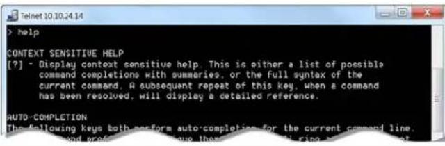 |
Note:
Use ? as a command parameter to see information about a given command's syntax.
history
Returns the most recently issued commands from the current Telnet session. Since many of the read user input a line at a time, the command history is used to keep track of these lines a information.
| Synopsis history | ||
| Options | Integer value specifying the maximum number of commands to return. | |
| Examples | historyDisplays the current command buffer. | |
| history 5Sets the history command buffer to remember the last 5 unique entries. | ||
Additional information You | can navigate the command history using the up arrow keys.This command supports the expansion functionality from which previous commands can be recalled from within a session. History expansion is performed immediately after a complete line is read.Examples of history expansion:* !! Substitute the last command line.* !4 Substitute the 4th command line (absolute as per 'history' command)* !-3 Substitute the command line entered 3 lines before (relative) | |
version
Returns the current firmware version.
| Synopsis version | |
| Example | versionReturns current firmware version information in a form so this:Commit: d033ddb2378357a871011eb820706dcaa64ec0e2System Version: PCC Premier 1.0.0 |
exit
Ends the command session and then closes the Telnet socket.
| Synopsis exit | |
| Example | exit |
Specifications
Camera Management and Video Output
| Control via RS-232 | Up to 8 cameras1 address book group | Control via IP network | Up to 80 cameras10 address book group |
| Image Control Parameters | Iris, Iris GainBacklight compensationRed Gain, Blue GainDetail, Chroma, GammaAuto White Balance/One-Push White Balance (depends on camera's capabilities) | HDMI OutputIP streaming decoder: H.264Protocol : RTSPSupported HDMI display resolutions: 1080p/60, 1080p/50, 720p/60, 720p/50 | |
Hardware
| System I/O ■ 8 RS-232 camera control ports on RJ-45 connectors■ Gigabit Ethernet port with PoE+ support■ HDMI output |
| Control console■ 7" capacitive touch panel display – Camera presets and administrative menu■ Illuminated rotary knobs – Focus (control, auto/manual) and Menu (display panel navigation)■ Rotary knobs – Pan, tilt, and zoom speed■ Illuminated pushbuttons – Group A and Group B camera selection■ 3-axis Hall effect joystick, single-button – Pan, tilt, and zoom |
Power, Physical and Environmental
| Power Requirements | PoE+ (Power over Ethernet) | Power Consumption | < 25W |
| Height | 5.125 in. (12.6 cm) | Operating temperature | 0° to +40°C (32° to 104°F) |
| Width | 17 in. (43.2 cm) | Operating humidity | 20% to 80% RH |
| Depth | 11 in. (27.9 cm) | Storage temperature | -5° to +60°C (23° to 140°F) |
| Weight | 7.0 lb (3.18 kg) | Storage humidity | 20% to 80% RH |
Specifications are subject to change without notice.

Troubleshooting and Care
Check the Indicator Lights Cheat Sheet first. If there is an issue, use this table to determine whether to call Vaddio Technical Support.
| What is it doing? | Possible causes Check and correct | |
| Nothing.The display is off and the buttons do not light up. | Power is not connected.the | Connect the mid-span power injector's power cord. |
| The network/PoE+ cable between the controller and mid-span power injector is | Check using known good cables.the bad. | |
| The wall outlet is not active (Check by finding out if it powers something else, such as a laptop or phone charger.) | a different outlet.it | |
| The camera controller or mid-span power injector is | contact your reseller or Vaddio Technical Support. | |
| No communication with any connected cameras (buttons for all IP cameras blue) | The P-camera controller is connected to the network. | Can you access the cameras' web interfaces with your browser?If so, check the connection from the power injector to the rest of the network. Ensure that the cable is connected to an active network port. |
| The cable on the network of the power injector is | Triside different cable.Indtact your network administrator if the problem persists. | |
| No communication with a specific IP-connected camera (button blinks blue) | The camera is not available | Wait a few minutes. This happens during camera firmware updates.Check whether the camera's power is connected. |
| The camera is not at that address. | AskIPsomeone in the room with the camera to press the Data Screen button on the camera's remote, and read the IP address off the display screen.Then update the camera's IP address in the address book. | |
| The camera requires a first update to communicate with the camera controller. | If the camera has not been updated to version 2.0.0 or later, download and install the latest firmware for the camera. | |
| The display connected to camera controller's HDMI output shows a pattern of bars | No camera is selected.No video stream is available from the selected camera may mean: | This is normal.- this |
| ■ The camera is connected via RS-232■ The camera does not have IP streaming capability■ IP streaming is not enabled on the camera | ||
| The display connected to camera controller's HDMI output shows a black screen | The display is powered off. Power on the display. | |
| The camera controller's video mute pattern is set to "black screen" and no video stream is available from the selected camera (always true for RS-232 connected cameras), or no camera is selected. | This is normal. | |
| The display connected to camera controller's HDMI output shows a blue screen | The selected IP-connected camera's video is muted, the camera is streaming screen as its video mute pattern. | Unmute the camera's video. and a blue |
| The display connected to camera controller's HDMI output shows random colors. | The color space or resolution set to a value that the codes not support. | Change the resolution or color space for this video output port (web interface, PCC Settings page). |
Operation, Storage, and Care
For smears or smudges on the product, wipe with a clean, soft cloth. Do not use any abrasive. Keep this device away from food and liquids.
Do not operate or store the device under any of the following conditions:
■ Temperatures above 40^ C ( 104^ F) or below 0^ C ( 32^ F)
■ High humidity, condensing or wet environments
■ Inclement weather
■ Severe vibration
■ Dry environments with an excess of static discharge
Do not attempt to take this product apart. There are no user-serviceable components inside.
Compliance Statements and Declarations of Conformity
Compliance testing was performed to the following regulations:
FCC Part 15 (15.107, 15.109), Subpart B Class A
ICES-003, Issue 54: 2012 Class A
EMC Directive 2004/108/EC Class A
EN 55022: December 2010 Class A
EN 55024: November 2010 Class A
KN22 2008 (CISPR 22: 2006) Class A
KN24 2008 (CISPR 24: 1997 + A1: 2000 + A2: 2002) Class A
IEC 60950-1:2005 (2nd Edition); Am 1: 2009 + Am 2: 2013 Safety
EN 60950-1: 2006 + A11: 2009 + A1: 2010 + A12: 2011 + A2: 2013 Safety
FCC Part 15 Compliance
This equipment has been tested and found to comply with the limits for a Class A digital device Part 15, Subpart B, of the FCC Rules. These limits are designed to provide reasonable protection harmful interference when the equipment is operated in a commercial environment. This equipment generates, uses, and can radiate radio frequency energy and, if not installed and used in accordance with the instruction manual, may cause harmful interference to radio communications. Operation of this equipment in a residential area is likely to cause harmful interference in which case the user will to correct the interference at his/her own expense.
Operation is subject to the following two conditions: (1) This device may not cause interference, and (2) This device must accept any interference including interference that may cause undesired operation of the device.
Changes or modifications not expressly approved by Vaddio can affect emission compliance and could void the user's authority to operate this equipment.
ICES-003 Compliance
This digital apparatus does not exceed the Class A limits for radio noise emissions from digital set out in the Radio Interference Regulations of the Canadian Department of Communications.
This product has been evaluated for Electromagnetic Compatibility under the EMC Directive for Emi and Immunity and meets the requirements for a Class A digital device. In a domestic environment product may cause radio interference in which case the user may be required to take adequate
Standard(s) To Which Conformity Is Declared:
CE
EMC Directive 2004/108/EC
EN 55022: December 2010 Conducted and Radiated Emissions
EN 55024: November 2010 Immunity
EN 61000-4-2: 1995 + Amendments A1: 1998 + A2: 2001 Electrostatic Discharge
EN 61000-4-3: 2006 + A1: 2008 Radiated Immunity
EN 61000-4-4: 2004 + Corrigendum 2006 Electrical Fast Transients
EN 61000-4-5: 2006 Surge Immunity
EN 61000-4-6: 2009 Conducted Immunity
EN 61000-4-8: 2010 Power Frequency Magnetic Field
EN 61000-4-11: 2004
Voltage Dips, Interrupts and Fluctuations
KN22 2008 (CISPR 22: 2006) Conducted and Radiated Emissions
KN24 2008 (CISPR 24: 1997 + A1: 2000 + A2: 2002) IT Immunity Characteristics
EN 61000-4-2 Electrostatic Discharge
EN 61000-4-3 Radiated Immunity
EN 61000-4-4 Electrical Fast Transients
EN 61000-4-5 Surge Immunity
EN 61000-4-6 Conducted Immunity
EN 61000-4-8 Power Frequency Magnetic Field
EN 61000-4-11
Voltage Dips, Interrupts and Fluctuations
IEC 60950-1: 2005 (2nd Edition); Am 1: 2009 + Am 2: 2013
Safety
EN 60950-1: 2006 + A11: 2009 + A1: 2010 + A12: 2011 + A2: 2013
Safety
Warranty Information
See Vaddio Warranty, Service and Return Policies posted on support.vaddio.com for complete details.
Hardware* warranty: Two (2) year limited warranty on all parts and labor for Vaddio manufactured
products. Vaddio warrants its manufactured products against defects in materials and workmanship for period of two years from the day of purchase, to the original purchaser, if Vaddio receives notice defects during the warranty. Vaddio, at its option, will repair or replace products that prove to be defective. Vaddio manufactures its hardware products from parts and components that are new or equivalent to new in accordance with industry standard practices.
Exclusions: The above warranty shall not apply to defects resulting from improper or inadequate maintenance by the customer, customers applied software or interfacing, unauthorized modifications or misuse, mishandling, operation outside the normal environmental specifications for the product, use of incorrect power supply, modified power supply or improper site operation and maintenance. OEM and special order products manufactured by other companies are excluded and are covered by the manufacturer's warranty.
Vaddio Service Department: Vaddio will test, repair, or replace the product or products without charge if
the unit is under warranty. If the product is out of warranty, Vaddio will test then repair the p products. The cost of parts and labor charge will be estimated by a technician and confirmed by customer prior to repair. All components must be returned for testing as a complete unit. Vaddio w accept responsibility for shipment after it has left the premises.
Vaddio Technical Support: Vaddio technicians will determine and discuss with the customer the criteria
for repair costs and/or replacement. Vaddio Technical Support can be contacted by email at support@vaddio.com or by phone at one of the phone numbers listed on support.vaddio.com.
Return Material Authorization (RMA) number: Before returning a product for repair or replacement
request an RMA from Vaddio's technical support. Provide the technician with a return phone number mail address, shipping address, product serial numbers and original purchase order number. Describe reason for repairs or returns as well as the date of purchase. See the General RMA Terms ar section for more information. RMAs are valid for 30 days and will be issued to Vaddio dealers users must return products through Vaddio dealers. Include the assigned RMA number in all correspondence with Vaddio. Write the assigned RMA number clearly on the shipping label of the returning the product. All products returned for credit are subject to a restocking charge. Special ord product are non-cancelable and not returnable.
Voided warranty: The warranty does not apply if the original serial number has been removed or if the
product has been disassembled or damaged through misuse, accident, modifications, use of incorrect power supply, use of a modified power supply or unauthorized repair.
Shipping and handling: Vaddio will not pay for inbound shipping transportation or insurance charges or
accept any responsibility for laws and ordinances from inbound transit. Vaddio will pay for outbound shipping, transportation, and insurance charges for all items under warranty but will not assume responsibility for loss and/or damage by the outbound freight carrier. If the return shipment appears damaged, retain the original boxes and packing material for inspection by the carrier. Contact your immediately.
Products not under warranty: Payment arrangements are required before outbound shipment for all out of warranty products.
Index
A
accessories 4
address book 12, 21, 23, 33
groups 21, 23
Address Book page (web) 15
Address Book screen (touch-panel) 12
admin login 13, 38
default 13
API 42, 49
syntax help 49
auto focus 43
B
backing up configuration data 39
brightness, touch-panel display 13
browser compatibility 13
buttons, camera select 7
C
cable 5
connectors 5
length, maximum 5
RS-232 pin-out 5
camera groups 21, 23, 33
renaming 33
selecting 23
camera presets 11, 28
recalling 11
setting 28
camera select buttons 7
cameras 21, 33-34
adding to groups 21
organizing 21
renaming 33-34
capabilities 2, 51
CCU scenes 12, 24
recalling 12
storing 24
CCU screen (touch-panel) 11
CCU settings 11
cheat sheet 9, 20
indicator lights 9
touch-panel display 20
web interface 20
cleaning 53
color codes for indicators 9
color settings 24
command history 50
commands, Telnet 42
compatibility 3, 8, 13
browsers 13
firmware 8
hardware 3
configuration data 39-40
exporting 39
importing 40
connection diagram 6
connector panel 5
console 7
D
damage, preventing 4-5
date and time 37
default settings, restoring 39, 49
DHCP 36
diagnostic logs 41
Diagnostics page (web) 18
diagram, connection 6
display, touch-panel 7
E
Ethernet/PoE+ port 5
expire idle sessions 38
exporting configuration data 39
F
factory defaults, restoring 39, 49
fault isolation 52
firmware update 40
firmware version 50
focus command 43
focus knob 7
G
getting help 19
groups 21, 23, 33
renaming 33
selecting 23
H
hardware setup 6
HdMI output
mute/inactive pattern 45
HDMI output 5, 45
display resolution 29
mute/inactive pattern 29
help 19
Help page (web) 19
home command 43
hostname 36
|
idle session time-out 38
importing configuration data 40
indicator lights 9
information, conference room 35
IP address 13, 36
default 36
discovering 13
IP settings for streaming 47
J
joystick 7, 29
direction (normal/reverse) 29
K
knobs 7
L
labels, room 35
lighting settings 12, 24
log files 41
login 13, 38
low-power state 30, 48
M
manual focus 43
maximum cable lengths 5
menu knob 7
N
network configuration 13, 36, 46
current 46
default 13, 36
Networking page (web) 17
NTP server 37
0
operating environment 53
organizing cameras 21
P
packing list 4
page 15-19
Address Book 15
Diagnostics 18
Help 19
Networking 17
PCC Settings 16
Room Labels 17
Security 18
System 19
pan command 44
pan speed 7, 44
part numbers 4
password 38
pause 49
PCC settings page (web) 16
performance specifications 51
pin-out, RS-232 5
ping command 46
PoE+ power 6
power down 30, 48
power up 7, 30, 48
presets 11, 28
recalling 11
setting 28
Presets screen (touch-panel) 11
product capabilities 2, 51
product returns and repairs 56
Q
quick reference 9, 20
indicator lights 9
touch-panel display 20
web interface 20
R
ready state 48
rebooting 32, 48
restoring configuration data 40
restoring default settings 39, 49
RJ-45 connectors 5
room information 35
Room Labels page (web) 17
RS-232 5
cable pin-out 5
communication settings 5
ports 5
S
scenes 12, 24
recalling 12
storing 24
Scenes screen (touch-panel) 12
screen (touch-panel) 11-13
Address Book 12
CCU 11
Presets 11
Scenes 12
Settings 13
Security page (web) 18
session management 38
Settings screen (touch-panel) 13
settings, default, restoring 49
software update 40
solving problems 52
speed 7, 43-45
focus 43
knobs 7
pan/tilt/zoom 44-45
standby state 10, 29-30, 48
camera behavior 29
static IP address 36
storage environment 53
streaming output 45
mute/inactive pattern 45
streaming settings 47
supported web browsers 13
System page (web) 19
system time 37
T
technical support 19
Telnet API syntax 49
Telnet session 42, 50
ending 50
history 50
temperature, operating and storage 53
tilt command 44
tilt speed 7, 44
time-out, idle session 38
time and date 37
time zone 37
touch-panel 7, 10
touch-panel display brightness 13
version, firmware 13, 50
W
warranty 4, 56
web browsers supported 13
web interface 15-19
Address Book page 15
Diagnostics page 18
Help page 19
Networking page 17
PCC Settings 16
Room Labels page 17
Security page 18
System page 19
what's in the box 4
Z
zoom command 45
zoom speed 7, 45
Vaddio, the Vaddio logo, PCC Premier, the PCC Premier logo, RoboSHOT, ClearSHOT, and Tri-Sy trademarks of Vaddio. All other trademarks in this document are the property of their respective © Copyright © 2016 Vaddio. All rights reserved.
Vaddio
131 Cheshire Ln., Suite 500
Minnetonka, MN 55305
vaddio™
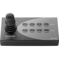
- PCC Premier
- Precision Camera Controller
- Contents
- About this Guide
- Product Overview
- Features
- Product Compatibility
- Installation
- Don't Void Your Warranty!
- Caution
- Unpacking the Camera Controller
- Connector Panel
- Cabling Notes
- Note
- RS-232 Serial Communication Settings and Port Pin-out
- Connector pin-out:
- Caution:
- Connecting the Controller
- Camera Controller Basics
- Powering Up the Cameras and Controller
- Control Console Features
- Touch-Panel Display
- Focus Knob
- Menu Knob
- Camera Select Buttons
- Joystick
- Pan, Tilt, and Zoom Speed Controls
- Ensuring Compatibility
- Indicator Lights Cheat Sheet
- Camera Indicators
- Touch-Panel Display Tour
- Behavior.
- Web Interface
- Compatible Web Browsers
- Opening the web interface
- A Quick Tour of the Web Interface
- Address Book
- PCC Settings
- Room Labels
- Networking
- Security
- Diagnostics
- System
- Help
- Working with the Camera Controller
- Touch-Panel Display Cheat Sheet
- Web Interface Cheat Sheet
- Setting up the Address Book
- support page.
- Define at least one group.
- Collect the hostnames or IP addresses of the cameras to be added to the Address Book.
- Add the cameras.
- Assign the cameras to groups.
- Selecting Camera Groups to Control
- Selecting Camera Groups from the Touch-Panel Display
- Selecting Camera Groups from the Web Interface
- Working with Lighting and Color Settings
- Selecting Lighting and Color Settings
- Adjusting Lighting and Color (CCU) Settings
- Saving Lighting and Color Adjustments
- Working with Camera Presets
- Setting Camera Controller Behavior
- Standby Settings
- Mute Settings
- Video Output Port and Picture Mode
- Joystick Settings
- Powering Down and Returning from Standby
- From the touch-panel display:
- From the web interface:
- Rebooting the Camera Controller
- Device Administration
- Renaming Cameras and Camera Groups
- To rename a group:
- To rename a camera:
- Adding Room Information
- Configuring the Camera Controller for Your Network
- Setting Date and Time
- Changing the Admin Password
- Managing Web Interface Sessions
- Backing Up or Copying a Configuration: Exporting Data
- Restoring Factory Defaults
- To restore the original factory settings:
- Importing Configuration Data
- To restore an exported configuration:
- Updating the Firmware
- Downloading the Diagnostic Log
- Telnet Command API
- camera focus
- camera home
- camera pan
- camera tilt
- camera zoom
- video mute pattern
- network ping
- network settings get
- streaming info dump
- system standby
- system reboot
- system factory-reset
- sleep
- Note:
- history
- version
- exit
- Specifications
- Troubleshooting and Care
- Operation, Storage, and Care
- Compliance Statements and Declarations of Conformity
- FCC Part 15 Compliance
- ICES-003 Compliance
- Warranty Information
- Index
- A
- B
- C
- D
- E
- F
- G
- H
- |
- J
- K
- L
- M
- N
- 0
- P
- Q
- R
- S
- T
- W
- Z
Brand : Vaddio
Model : PCC Premier
Category : Joystick