951-145 - Fitness Equipment Kayoba - Free user manual and instructions
Find the device manual for free 951-145 Kayoba in PDF.


| Product Type | Fitness Equipment |
| Brand | Kayoba |
| Model | 951-145 |
| Dimensions (L x W x H) | Approx. 180 x 70 x 120 cm |
| Weight | Approx. 45 kg |
| Maximum User Weight | 120 kg |
| Power Supply | Electric, 220-240V, 50Hz |
| Motor Power | 2.0 HP |
| Speed Range | 0.8 - 16 km/h |
| Incline Range | 0 - 12% |
| Display Type | LCD with backlight |
| Main Functions | Walking, jogging, running, heart rate monitoring, preset programs |
| Heart Rate Monitoring | Hand grip sensors and chest strap compatible |
| Safety Features | Emergency stop key, safety belt clip |
| Folding Design | Yes, with hydraulic soft-drop |
| Transport Wheels | Yes, for easy relocation |
| Running Belt Size | 132 x 45 cm |
| Maintenance | Regular lubrication of belt, cleaning of dust |
| Cleaning | Wipe with damp cloth, avoid solvents |
| Spare Parts Availability | Motor, belt, control board, rollers available from manufacturer |
| Warranty | 2 years on motor, 1 year on parts |
| Manual Languages | English, Norwegian, Polish, Swedish |
Frequently Asked Questions - 951-145 Kayoba
User questions about 951-145 Kayoba
0 question about this device. Answer the ones you know or ask your own.
Ask a new question about this device
Download the instructions for your Fitness Equipment in PDF format for free! Find your manual 951-145 - Kayoba and take your electronic device back in hand. On this page are published all the documents necessary for the use of your device. 951-145 by Kayoba.
USER MANUAL 951-145 Kayoba
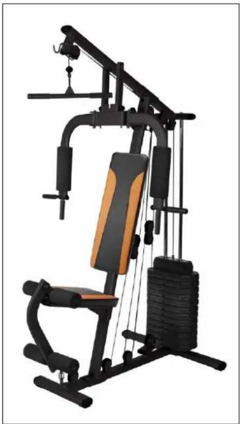
Operating instructions for home gym
951-145
natural_image
Modern gym machine with black frame, orange arm, and black load-bearing frame (no text or symbols visible)SV Bruksanvisning i original
NO Bruksanvisning i original
EN Operating instructions in original
SVENSKA 3
BESKRIVNING 3
Delar....4
MONTERING 5
Steg 1....5
Steg 2....6
Steg 3....7
Steg 4....8
Steg 5....9
Fitting the cables 40
BESKRIVNING
 |  |  | 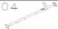 | 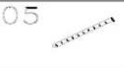 |
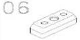 | 07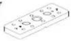 | 08 | 09 | 1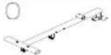 |
11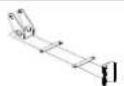 | 12 | 13 | 14 | 15 |
| 16[YD30] | 17 | 18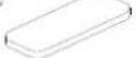 | 19[ASTZ] | 20[DEZY] |
| 21[Y5A0] | 22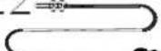 | 23[Y0HC] | 24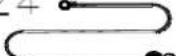 | 25 |
26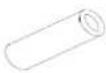 | 27 | 28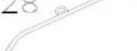 | 29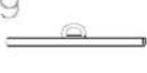 | 30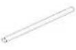 |
31 | 32 | 33 | 34 | 35 |
36 ∅10.5x56L ∅10.5x56L | 37[DTCB]∅48x∅13x3t | 38 | 39 | 40[CGH3] |
41 | 42 | 43 30*60 30*60 | 44 25*50 25*50 | 45 ∅25 ∅25 |
46 | 47 | 48[XC0Z] | 49[DACS] | 50[WAWC]M12X95mm |
| 51[4038]M12X80mm | 52 M10X100mm M10X100mm | 53 M10X60mm M10X60mm | 54 M10X50mm M10X50mm | 55 M10X30mm M10X30mm |
56 M10X25mm M10X25mm | 57 M8X60mm M8X60mm | 58 M8X55mm M8X55mm | 59[HWEY] | 60 M8X15mm M8X15mm |
61 M6X30mm M6X30mm | 62 M10 M10 | 63 M16 M16 | 64 M12 M12 | 65[crxd]M10 |
66  | 67 [3003] [3003] | 68[3XTS] | 69[ST6C] | 70 [SKGD] [SKGD] |
  | 72[transl] | 73[23TS] | 74 | 75[XYZD] |
| [SY7X] | 77 |
Delar
Steg 1
Steg 2
Steg 3
Steg 4
Steg 5
OBS! Lindistans
natural_image
Technical line drawing of a mechanical lifting device with pulleys and weights (no text or symbols)Trinn 01
Trinn 02
Trinn 03
-
Sett et ellipseformet endedeksel på 40*80 mm (75) og et ellipseformet endestykke på 30*60 mm (43) på begge endene av den øvre tverrstangen (10).
-
Fest den øvre tverrstangen (10) til den vertikale stangen (04) med boltene (52), skiven (70) og mutrene (65) på oversiden, og koble styrestengene (02) til den øvre tverrstangen (10) med bolt (56) og skive (70) som vist.
-
Fest gummidemperen (42) til den vertikale stangen (04).
-
Fest trinseblokken (19) til den vertikale stangen (04), bruk med bolter (57) skiver (71) og muttere (66).
Trinn 04
Trinn 05
MERK! Distansestykke for kabel
natural_image
Technical line drawing of a mechanical lifting device with pulleys and weights (no text or symbols)Krok 1
Krok 2
Krok 3
Krok 4
Krok 5
natural_image
Technical line drawing of a mechanical lifting device with pulleys and weights (no text or symbols)NOTE! Assembly tool supplied.
ASSEMBLY
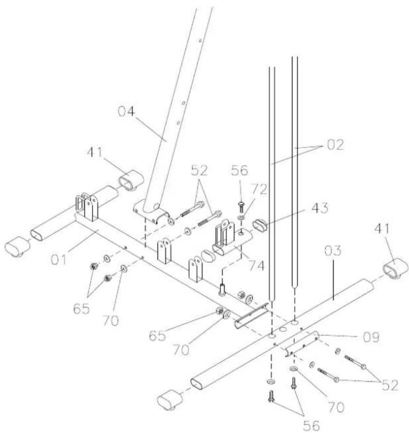
Step 1
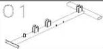
- Place the oval rubber damper (41) on the ends of the base frame (01) and rear crossbar.
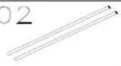
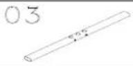
- Fit the guides (02) in the crossbar (03) with the bolt (56) and washer (70) as illustrated.
- Fit the base frame (01) on the crossbar (03) with the plate (09) and bolts (52), washers (70) and nuts (65) as illustrated.
Tighten all the bolt connections with the supplied tool.
-
Fit the vertical bar (04) on the base frame (01) with the bolts (52), washers (70) and nuts (65) as illustrated.
-
Fit the block (74) for the pulley on the base frame (01) with the hex bolts (56) and washers (72) as illustrated.
-
Place the oval end cap 30 x 60 mm (43) on the pulley block (74) as illustrated.
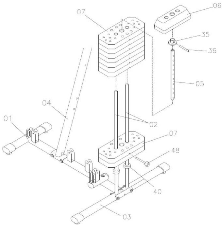
Step 2
- Fit the rubber dampers (40) on the guide (02).
- Put the weights (07) and top plate (06) on the guide (02) as illustrated.
- The groove for the weight pin in the weights must face downwards.
- Fit the round bushing (35) on the weight pin (05). Lock the weight pin (05) at the top plate (06) with the pin (36) as illustrated.
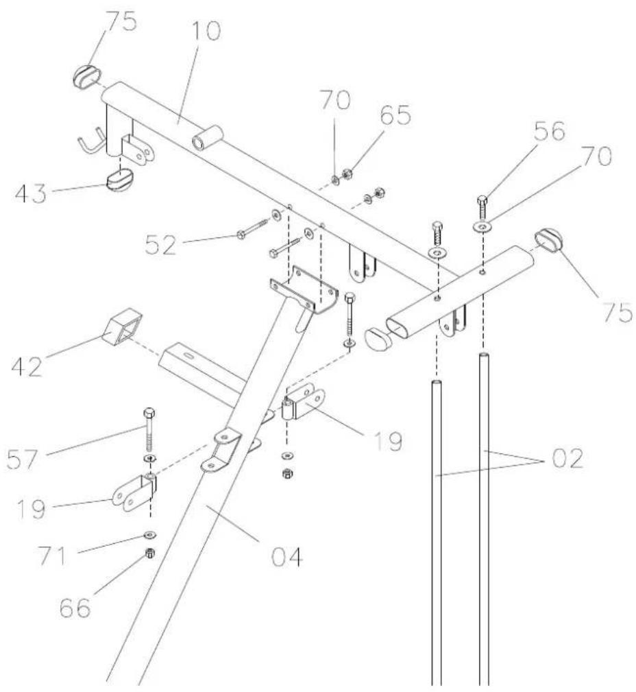
Step 3
- Place the oval end caps 40 x 80 mm (75) and 30 x 60 mm (43) on both ends of the top bar (10).
- Attach top cross beam (10) onto the vertical beam (04) use with bolts (52) washer (70) and nuts (65), from top side and connect the guide rods (02) to the top cross beam (10) with bolt (56) washer (70) as shown.
- Fit the rubber damper (42) on the vertical bar (04).
- Fit the block (19) for the pulley on the vertical bar (04) with the bolts (57), washers (71) and nuts (66).
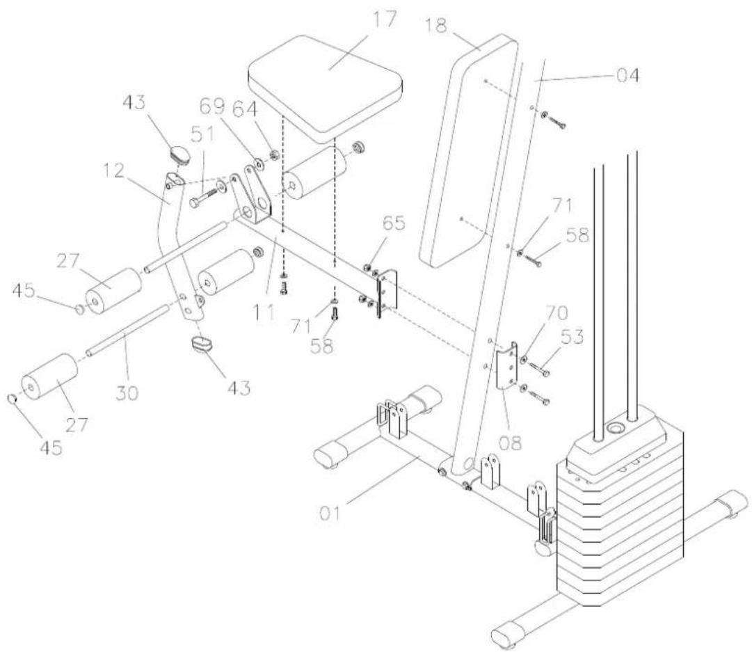
Step 4
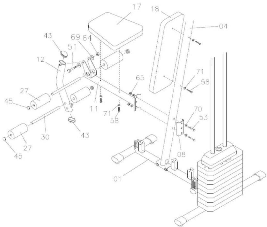
- Place the oval end cap 30 x 60 mm (43) on both ends of the bar (12) for leg extensions/curls.
- Fit the seat bracket (11) on the vertical bar (04) with the plate (08) and bolts (53), washers (70) and nuts (65) as illustrated.
- Fit the bar (12) for leg extensions/curls on the seat bracket (11) with bolts (51), washers (69) and nuts (64) as illustrated.
- Fit the backrest (18) on the vertical bar (04) with bolts (58) and washers (71) as illustrated.
- Fit the seat (17) on the seat bracket (11) with bolts (58) and washers (71) as illustrated.
- Place the pad holders (30) in their holes.
- Put the pads (27) for the bar for leg extensions/curls on the pad holders (30).
- Place the round end cap 25 mm (45) on the pad holders (30).
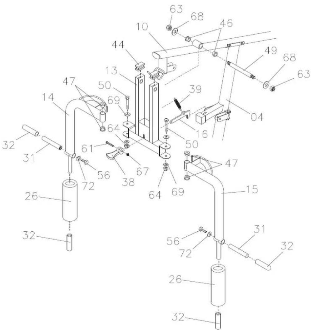
Step 5
- Place the square end cap 20 x 40 mm (44) on the bar (13) for the bench press.
- Fit the oil bushings (47) on the top bar (10) as illustrated.
- Fit the bar (13) for the bench press on the top bar (10) with bolts (49), washer (68) and nyloc nut (63) as illustrated.
- Fit the pads (26) for the pec handle and grip (32) on the pec handle (14, 15) as illustrated.
- Fit the handle pipe (31) and grip (32) on the pec handle (14, 15) with the bolt (56) and washer (72) as illustrated.
- Fit the pec handles (14, 15) on the bar (13) for the bench press with the bolt (50), washer (69) and nylon nut (64) as illustrated.
- Fit press pin (16) into press bar (13) use fastening (38) with bolt (61), nylon nut (67) and spring (39) as illustrated.
Fitting the cables
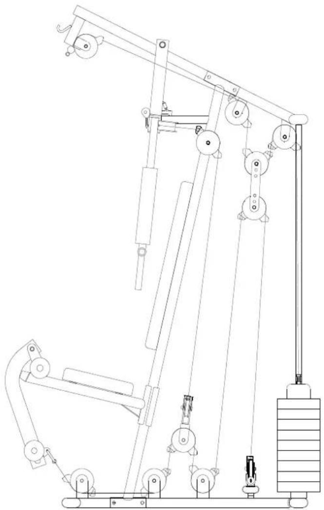
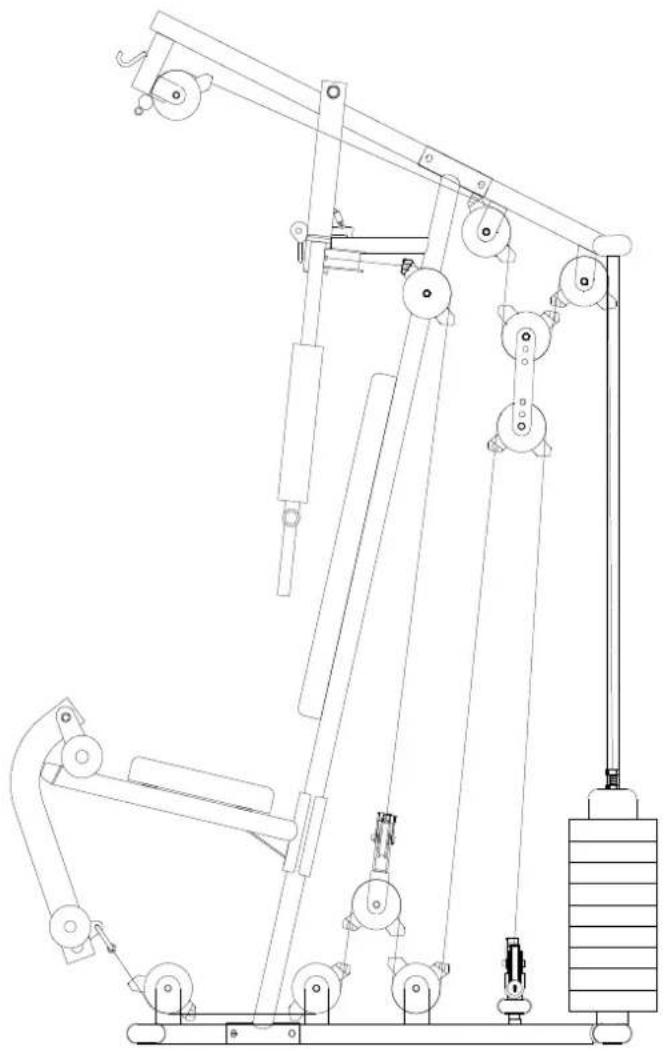
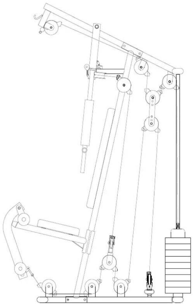
1. Threading on the top cable 2350 mm (22)
Thread the cable end without ball over pulley 1, over pulley 2, down and round pulley 3, through the block for the floating pulley, up and over pulley 4, then down and fastened in the weight rack 5 with the M12 bolt and washer (37) as illustrated.
2. Threading the cable for the pec handle 2750 mm (23)
Fasten one end of the pec handle cable in the pec handle as illustrated in the diagram for the pec handle unit, and use hex bolt M10 x 30 mm (55), nut M10 (62), washer M10 (70) and nyloc nut M10 (65) to fasten the cable at the unit 6. Now pull the other end of the cable over pulley 7, down and round pulley 8, through the pulley block (20) for the pec handle and over pulley 9, and fasten in the pec handle as illustrated in the diagram for the pec handle unit 10 with hex bolt M10 x 30 mm (55), nut M10 (62), washer M10 (70) and nyloc nut M10 (65).
3. Threading the lower cable 3750 mm (24)
Thread the cable end without ball under the pulley 11, up round pulley 12, through the block for the floating pulley, down and under pulley 13, up and round pulley 14, through the block for the floating pulley, down and under pulley 15, under pulley 16 and fasten the snap hook on the end of the cable in the bar (12) for leg extensions/curls 17 and secure the cable.
NOTE! If the cables are not long enough, lengthen them with the chain and fasten to the snap hook.
- Fit the grip (32) on the lat bar (28) and on the curl bar (29) as illustrated.
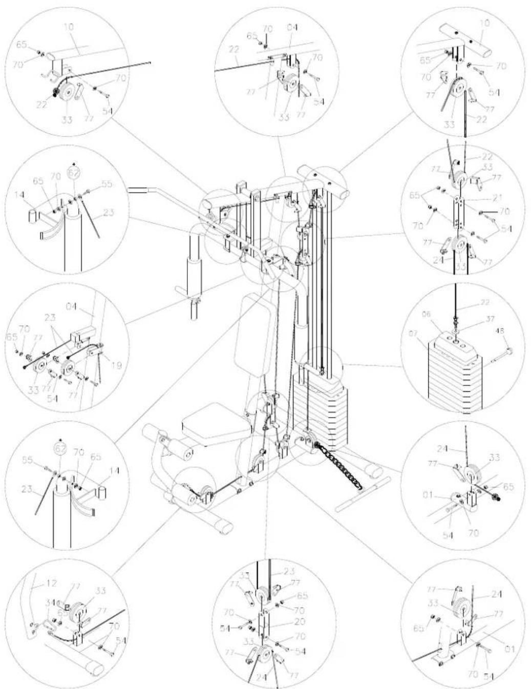
NOTE! Cable spacing
natural_image
Technical line drawing of a mechanical lifting device with pulleys and weights (no text or symbols)IMPORTANT! Check that all the cables are correctly fitted before using the machine.
Jula reserves the right to make changes. In the event of problems, please contact our service department.
www.jula.com
- Operating instructions for home gym
- SVENSKA 3
- BESKRIVNING
- Steg 1
- Steg 2
- Steg 3
- Steg 4
- Steg 5
- Trinn 01
- Trinn 02
- Trinn 03
- Trinn 04
- Trinn 05
- Krok 1
- Krok 2
- Krok 3
- Krok 4
- Krok 5
- ASSEMBLY
- Step 1
- Step 2
- Step 3
- Step 4
- Step 5
- Fitting the cables
- Threading on the top cable 2350 mm (22)
- Threading the cable for the pec handle 2750 mm (23)
- Threading the lower cable 3750 mm (24)
Brand : Kayoba
Model : 951-145
Category : Fitness Equipment