
TC7060D - Tumble dryer UPO - Free user manual and instructions
Find the device manual for free TC7060D UPO in PDF.


| Product Type | Condenser Tumble Dryer |
| Brand | UPO |
| Model | TC7060D |
| Capacity | 7 kg (dry laundry) |
| Dimensions (W x H x D) | 59.5 x 85.0 x 59.0 cm |
| Power Supply | 230 V ~ 50 Hz |
| Drying Programmes | Cotton, Synthetics, Delicates, Wool; Timed (Cotton 0-160 min, Synthetics 0-120 min, Cooling 20 min) |
| Drying Levels | Extra Dry, Wardrobe Dry, Iron Damp, Very Damp |
| Control Panel | Electronic with display, programmer knob, start button, drying selector, anti-crease, delayed start, beep silencer |
| Door Reversible | Yes (by qualified technician) |
| Condensation Drain | Removable reservoir or direct connection to drainage system |
| Filtration System | Door fluff filter, loading aperture filter, condenser |
| Maintenance | Empty reservoir after each cycle; clean filters after each cycle; clean condenser 2-3 times per year |
| Anti-Crease Function | Yes (60 min drum rotation after cycle) |
| Delayed Start | Up to 16 hours |
| Alarm Indicators | Reservoir full, cycle end, anti-crease active |
| Stacking Kit Compatible | Yes (optional, for mounting on front-loading washing machine) |
| Internal Light | Available on some models (bulb max 15 W) |
| Safety | Automatic stop if reservoir full; child safety door; thermal protection (if applicable) |
| Warranty | Refer to dealer |
Frequently Asked Questions - TC7060D UPO
User questions about TC7060D UPO
0 question about this device. Answer the ones you know or ask your own.
Ask a new question about this device
Download the instructions for your Tumble dryer in PDF format for free! Find your manual TC7060D - UPO and take your electronic device back in hand. On this page are published all the documents necessary for the use of your device. TC7060D by UPO.
USER MANUAL TC7060D UPO
natural_image
Black-and-white photo of a family celebrating together, with one person lifting a child's leg and another smiling (no text or symbols visible)
SVENSKA 4-12

OMI 13-22

RSK 23-32

DANSK 33-42

ENGLISH 43-51
Bäste Kund,
INNEHÅLLSFÖRTECKNING


ANMÄRKNINGAR OCH RÅD FÖR ANVÄNDAREN 3-4
- Tekniska data 3

ESKRIVNING AV MASKINEN 5
- Extra tillbehör 5

STALLATION AV MASKINEN 5-7
Installation 5
EXTRA TILLBEHÖR
natural_image
Close-up of a mechanical ventilation unit with a circular vent and side brackets (no text or symbols visible)natural_image
Hand holding a plug inserted into an electrical socket, with a symbol indicating the power outlet (no text or labels present)natural_image
Mechanical assembly diagram showing a bracket with attached spring and pipe, no text or symbols present
natural_image
Technical diagram of a mechanical component with internal channels and mounting holes (no text or symbols)ÖPPNING OCH OMHÄNGNING AV LUCKA
natural_image
Diagram of a washing machine with a fan open and internal tubing, labeled with number 8 (no text or symbols on the diagram itself)natural_image
Illustration of a washing machine with internal components and ventilation duct (no text or symbols)natural_image
Hand pressing a button on a computer interface (no text or symbols visible)
natural_image
Person installing or adjusting a metal bracket with mounting holes (no text or symbols visible)RENGÖRING OCH UNDERHÅLL
natural_image
Close-up of a mechanical component with a meshed panel and an upward arrow, no visible text or symbols
natural_image
Technical illustration of a mechanical component with a circular opening and internal blades (no text or symbols)
natural_image
Interior view of a car showing a door opening with internal compartments and a numbered label (15), no text or symbols present.RENGÖRING OCH UNDERHÅLL

natural_image
Diagram of a vehicle air vent system with directional arrows indicating flow or movement (no text or symbols present)natural_image
Illustration of a hand holding a handheld device next to a battery stack with curved arrows indicating rotation (no text or symbols)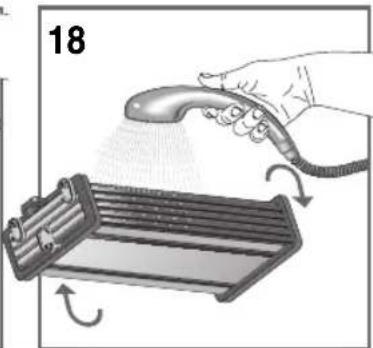
natural_image
Illustration of a hand using a spray gun to press a device with a rack (no text or symbols)natural_image
Line drawing of a rectangular mechanical component with mounting feet (no text or symbols)natural_image
Technical line drawing of a mechanical assembly with no visible text or symbolsnatural_image
Technical line drawing of a mechanical assembly with no visible text or symbols
FULLBORDA INSTALLATIONEN
natural_image
Close-up of a mechanical ventilation unit with a circular vent and mesh grille (no text or symbols visible)natural_image
Illustration of a hand holding a tool near a refrigerator (no text or symbols)SÄHKÖVERKKOON LIITÄNTÄ
natural_image
Hand holding a plug inserted into an electrical socket, with a symbol indicating a fuse or switch (no text or labels present)natural_image
Mechanical assembly diagram showing a bracket with attached pipe and valve (no text or symbols)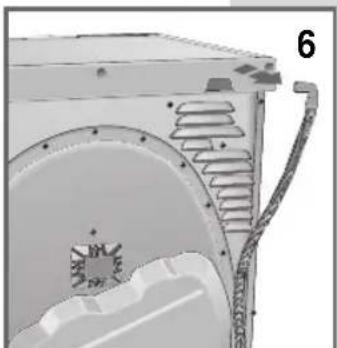
natural_image
Technical diagram of a mechanical component with internal channels and mounting features (no text or symbols)LUUKUN AVAAMINENJA SUUNNAN VAIHTAMINEN

natural_image
Illustration of a hand pressing down on a door panel with directional arrows indicating movement (no text or symbols)natural_image
Diagram of a microwave oven with ventilation ducts and fan opening (no text or symbols)natural_image
Exterior view of a washing machine with visible door, vent, and control buttons (no text or symbols)LAUHDEVESISÄILIÖN TYHJENNYS
natural_image
Hand placing a component into a device (no visible text or symbols)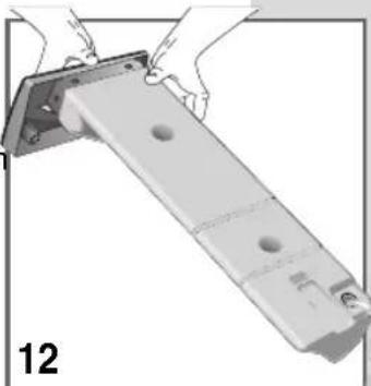
natural_image
Person assembling a mechanical component with a bracket (no text or symbols visible)PUHDISTUS JA HUOLTO
natural_image
Diagram of a device with a mesh panel and an upward arrow, no visible text or symbols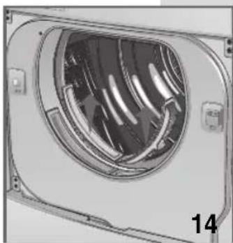
natural_image
Technical illustration of a mechanical component with a circular opening and internal blades (no text or symbols)
natural_image
Interior view of a vehicle showing a door opening with internal compartments and a directional arrow indicating flow (no text or symbols)PUHDISTUS JA HUOLTO
natural_image
Diagram of a device interior showing a rack-mounted unit with a directional arrow indicating movement (no text or symbols present)natural_image
Illustration of a hand holding a handheld device next to a battery pack with rotation arrows (no text or symbols)
natural_image
Illustration of a hand spraying a hairdryer onto a device with motion arrows (no text or symbols)natural_image
Line drawing of a rectangular mechanical component with mounting feet (no text or symbols)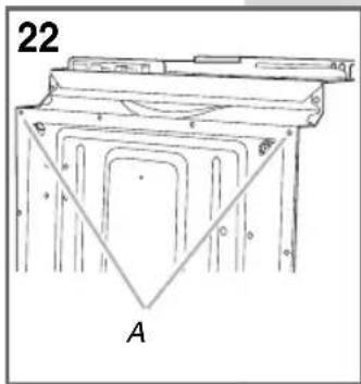
natural_image
Technical line drawing of a mechanical assembly with no visible text or symbolsnatural_image
Technical line drawing of a mechanical assembly with no visible text or symbols
EKSTRAUTSTYR
natural_image
Close-up of a white industrial fan or vent with a circular grille and ventilation slots, no visible text or symbols.natural_image
Illustration of a hand holding a small object near a cabinet, with arrows indicating rotation or movement (no text or symbols)natural_image
Illustration of a hand holding a plug inserted into an electrical socket, with a symbol indicating the same electrical symbol (no text or labels present)KOPLE TIL DET ELEKTRISKE SYSTEMET
natural_image
Mechanical assembly diagram showing a bracket with attached spring and pipe (no text or symbols)
natural_image
Technical diagram of a mechanical component with internal channels and mounting holes (no text or symbols)ÅPNE OG OMHENGSLE DØREN
natural_image
Diagram of a washing machine with a fan open and internal blades connected by coiled tubing (no text or symbols)▼ Døren kan omhengsles etter behov (fi g. 8).
FORHOLDSREGLER FOR T∅Y
TIDSINNSTILT PROGRAM
| BOMULL | 7.0 kg. | 0-160 min. |
| SYNTETISK | 3.5 kg. | 0-120 min. |
| NEDKJ∅LING | 20 min | |
T∅RKING
natural_image
Interior view of a washing machine with visible fan and door (no text or symbols)natural_image
Hand pressing a button on a mechanical device (no visible text or symbols)
natural_image
Person installing or adjusting a metal bracket with mounting holes (no text or symbols visible)RENGJ∅RING OG VEDLIKEHOLD
natural_image
Diagram of a device with a mounted screen and ventilation grille, showing an upward arrow (no text or symbols)natural_image
Technical illustration of a mechanical component with internal blades and mounting brackets (no text or symbols)
natural_image
Interior view of a vehicle showing a door opening with internal compartments and a numbered label (15), no text or symbols present.RENGJ∅RING OG VEDLIKEHOLD

natural_image
Diagram of a vehicle air vent system inside a vehicle, showing airflow direction and component placement (no text or symbols)natural_image
Illustration of a hand holding a handheld device next to a battery stack with curved arrows indicating rotation (no text or symbols)
natural_image
Illustration of a hand using a spray gun to dispense or spread materials around a tray (no text or symbols)natural_image
Line drawing of a rectangular mechanical component with mounting feet (no text or symbols)A. Fjern de to skruene (kun for utluftningstørketromler, fi g. 22).

natural_image
Technical line drawing of a mechanical component with triangular support and labeled point A (no text or symbols beyond labels)B. Fest konsollene (fi g. 23/24).

natural_image
Technical line drawing of a mechanical assembly with no visible text or symbolsnatural_image
Technical line drawing of a mechanical assembly with no visible text or symbols
natural_image
Technical line drawing showing a hand holding a mechanical component and a separate view of a circular component labeled A (no text or symbols present)TILBEH∅R
natural_image
Close-up of a mechanical ventilation unit with a circular fan and ventilation duct (no text or symbols visible)natural_image
Illustration of a hand holding a tool near a cabinet, with arrows indicating rotation (no text or symbols)TILSLUTNING TIL STRÖMFORSYNINGEN
natural_image
Hand holding a plug with an open socket, symbolizing electrical power or electrical switch (no text or symbols present)natural_image
Mechanical assembly diagram showing a pipe connection with a bracket and housing (no text or symbols)
natural_image
Technical illustration of a mechanical component with internal channels and mounting holes (no text or symbols)ÅBNING OG ÆNDRING AF LÅGENS DREJNING

natural_image
Illustration of a hand pressing down on a door panel with directional arrows indicating movement (no text or symbols)natural_image
Diagram of a microwave oven with ventilation ducts and fan opening (no text or symbols)natural_image
Interior view of a washing machine with visible door, fan, and buttons (no text or symbols)natural_image
Hand pressing a button on a computer monitor (no visible text or symbols)natural_image
Person assembling a metal bracket with mounting holes (no text or symbols visible)RENG∅RING OG VEDLIGEHOLDELSE
natural_image
Diagram of a device with a mesh component and an upward arrow, no visible text or symbolsnatural_image
Technical illustration of a mechanical component with internal blades and mounting brackets (no text or symbols)
natural_image
Interior view of a car showing a vehicle's rear compartment with a handle and internal components (no text or symbols visible)RENG∅RING OG VEDLIGEHOLDELSE

natural_image
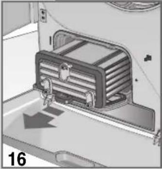
Diagram of a device interior showing a ventilation duct and fan assembly (no text or symbols)Drej de 3 greb over til lodret position, og tag kondensatoren ud (fi g. 16).

natural_image
Illustration of a hand holding a flexible hose next to a battery with curved arrows indicating rotation (no text or symbols)
natural_image
Illustration of a hand spraying a spray gun onto a device with motion arrows (no text or symbols)natural_image
Line drawing of a rectangular electronic device with mounting feet and a label '21' (no text or symbols on the device itself)natural_image
Technical line drawing of a mechanical assembly with no visible text or symbols- Skub tørretumbleren frem mod vaskemaskinens forside.
Stablebøjlerne glider henover vaskemaskinens bagkant og når den rette position (fi g. 25/26).

natural_image
Technical line drawing of a mechanical assembly with no visible text or symbols
AFSLUTNING AF INSTALLATIONEN
Thank you for choosing our product.
Please read these instructions carefully before connecting and using the appliance.
Knowledge of the operating principles will help guarantee correct and safe use of the appliance.
This instruction booklet contains the technical characteristics of the drier and is full of useful information regarding its operation, all designed to help you get the best out of your appliance.
If the appliance is sold or handed over for use by others, remember to give the new user the instruction booklet.
CONTENTS

NOTES AND ADVICE FOR THE USER 59-61
• Technical information 59
DESCRIPTION OF THE APPLIANCE 61
- Optional accessories 61
INSTALLING THE APPLIANCE 61-63
- Installation 61
- Levelling the drier 62
- Connecting to the mains supply 62
- Connecting the condensation drain to the drainage system. 62
- Changing the door opening direction 63
USING THE DRIER
• Precautions for fabrics 63
- Recommendations prior to drying 63
• Description of the control panel 64
- Programme
• How to dry 65
63
63
64
65
MAINTENANCE
- Internal light 65
- Draining the condensation reservoir
• Cleaning and maintenance - Troubleshooting
- Resolving problems 67
65
66
66-67
67
67
63-65
65
65-67
NOTES AND ADVICE FOR THE USER

TECHNICAL DATA
| Dimensions: | Width cm.: | 59.5 |
| Height cm.: | 85.0 | |
| Depth cm.: | 59.0 | |
| Max. capacity | 7 kg dry | |
| Power rating | see characteristics plate | |
| Voltage | see characteristics plate |
MODEL:
SERIAL NUMBER:
DATE OF PURCHASE:
This appliance has been designed for use as a domestic drier. Any other use is considered as improper and therefore dangerous.
▼ Keep this instruction book near to the appliance always, so that it can be easily consulted when necessary.
▼ Any modifications or attempts to interfere with the appliance can be dangerous for the user and may damage the product.
On delivery of the appliance, check that it has not been damaged during transport. If any damage is discovered, report the matter to the retailer immediately.
▼ Do not cover the drier with washing or any other items.
When positioning the appliance, ensure that the power supply cable is not kinked or squashed and is accessible.
▼ Always close the door after using the drier. This will prevent children from leaning on the door and possibly overturning the drier.
The appliance must not be used by children unless supervised.
▼ Do not use the drier for drying dirty clothes.
▼ Never dry items that have been soiled with substances such as cooking oil, petroleum, aceton e, alcohol, petrol, kerosene, stain removers, turpentine, wax.
▼ Remove these substances in a hot wash using an additional quantity of detergent prior to loading the items in the drier.
Do not dry items such as foam rubber, latex, raincoats, waterproof fabrics, rubber mats, preformed items, clothes or cushions with foam rubber inserts, as these may melt and damage other items in the washing or even the appliance itself.
▼ Fabric softeners, or similar products, must be used respecting the manufacturer's instructions on the packaging.
If the appliance is sold or given away, remember to hand over this instruction book with it. This will help the new owner use the drier both correctly and safely.
Do not attempt to repair any appliance faults alone, in that repairs carried out by a non-professional may cause serious damage and will invalidate any rights to repairs under guarantee.
▼ Repairs to the appliance can only be carried out by personnel authorised by the customer service centres. All repairs must make use of original spare parts only.
▼ Spin dry or wring the washing well before
loading it into the drier. Spun dry washing will dry quicker.
▼ Clean the filter thoroughly each time the drier is used in order to guarantee perfect air circulation.
▼ Never insert or remove the plug from the mains socket with wet hands.
The drier must be connected to a mains socket fitted with an efficient earth complying with current safety standards.
Do not use extension leads or multiple plug adapters to connect the appliance to the mains supply.
▼ Do not expose the appliance to atmospheric agents.
When servicing or cleaning the appliance, remember to disconnect it from the mains supply.
Do not pull the power supply cable to unplug the appliance from the mains supply. Pull the plug only.
This appliance is marked as complying with European Directive 2002/96/EC, Waste Electrical and Electronic Equipment (WEEE). Make sure that the product is disposed of in a correct manner. The user is obliged to contribute towards preventing any negative consequences for health and the environment.

The symbol
fixed to the product or duments signifi es that the treated as normal domestic delivered to an authorised to enable the electric and not to be recycled.
accompanying documents signifies that the product must not be treated as normal domestic refuse, but must be delivered to an authorised collection centre to enable the electric and electronic equipment to be recycled.
When disposing of the appliance, comply with local waste disposal regulations.
For further information on the treatment, recovery and recycling of this product, refer to the appropriate offi ces, local domestic waste collection service or the retailer from where the appliance was purchased.

Warning!!! Surfaces on which this symbol appears may heat up during normal operation
THE MANUFACTURER WILL NOT BE HELD RE SP ON SIBLE FOR A NY INCIDENTS RESULTING FROM NON-COMPLIANCE WITH SAFETY STANDARDS OR THE REQUIREMENTS OF THIS INSTRUCTION BOOK.
DESCRIPTION OF THE APPLIANCE
1 Drum door.
2 Drum door fi lter.
3 Upper condensation water reservoir*. (The condensation is collected in this reservoir when the condensation drain hose is not connected directly to the drainage system).
4 Control panel.
5 Drier drum.
6 Drum mouth fi iter.
7 Rating plate.
8 Lower condensation water reservoir*.
9 Adjustable feet
10 Condenser door.
11 Lower door.
12 Serial number.
* according to model

OPTIONAL ACCESSORIES
The drying kit for delicate items or shoes consists of a removable rack and is used when drying items requiring special treatment.
INSTALLING THE APPLIANCE

INSTALLATION

natural_image
Close-up of a white industrial air vent with a circular fan and ventilation grille (no text or symbols visible)▼ Installation must be carried out by qualified personnel in line with the instructions supplied by the manufacturer. Incorrect installation may result in damage and/or injury.
▼ Do not install the drier in rooms subject to freezing temperatures. Freezing temperatures could damage the electronics.
▼ Position the drier in a well-ventilated room.
▼ Do not cover the ventilation hole on the back (fi g. 2) and do not place the drier on thick carpet.
▼ Clean the inside of the drying drum using a damp cloth to remove any dust deposits.
WARNING!!! A stacking kit MUST be installed if products will be stacked. Note! If the drier is placed on top of a washing machine or other product, please read the information of stacking kit.
LEVELLING THE DRIER
Adjustable feet. Place the drier upright so that it rests firmly on all four feet. Level the drier by adjusting the feet as follows:
▼ Lift the drier slightly.
▼ Adjust the feet to the correct height (fi g. 3).
▼ Lower the drier.
NB. A badly levelled appliance may cause damage to the bearings and lead to their premature wear. This drier does not need to be anchored to the floor.

natural_image
Illustration of a hand holding a small object near a window, with motion arrows indicating rotation (no text or symbols)CONNECTING TO THE MAINS SUPPLY
▼ Make sure that the voltage indicated on the identification plate attached to the back of the appliance corresponds to that of the mains supply.
All cut-outs, electric wiring and mains sockets must have a rating such that enables them to support the maximum load indicated on the identification plate.
▼ Once the appliance has been installed, it must be connected to the mains supply through a single-pole switch.
The mains supply to which the appliance is connected must be fitted with an earthing system. If this is not the case, the manufacturer will not be held liable for any incidents that may occur (fi g. 4).
If the power supply cable is damaged in any way, contact the appropriate specialised customer technical service centre.
The drier must not be connected to the mains supply using indirect methods such as extension leads or multiple adapters.
▼ Position the appliance so that the power supply cable is easily accessible for disconnection when the need arises.

natural_image
Hand holding a plug inserted into an electrical socket, with a symbol and number 4 nearby (no text or labels on the diagram itself)Important: On completion of the drying cycle, disconnect the appliance from the mains supply to prevent young children from operating the drier.
CONNECTING THE CONDENSATION DRAIN TO THE DRAINAGE SYSTEM
The condensation can be collected in the reservoir (fi g. 10) or, alternatively, the hose can be connected directly to the drainage system.
In this case, the collected water is pumped out.
To connect the condensation hose directly to the drainage system, proceed as follows:
Before starting any operations, unplug the appliance from the mains socket.
Extract the hose on the back of the appliance by pulling it from its housing, (fi g. 5/6) and insert it in the waste water pipe.

natural_image
Mechanical assembly diagram showing a pipe connection with a bracket and housing (no text or symbols)
natural_image
Technical illustration of a mechanical component with no visible text or symbolsOPENING THE DOOR AND CHANGING THE OPENING DIRECTION

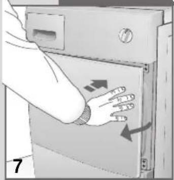
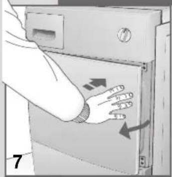
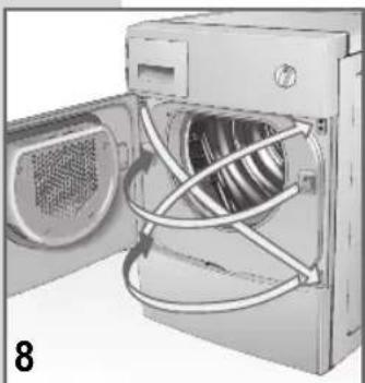
▼ Press the right side of the door (fi g. 7) to open it. If the door has been reversed, press the left side.
natural_image
Diagram of a washing machine with internal fan blades and ventilation slots (no text or symbols)The direction of the drum door opening can be modified according to needs (fi g. 8).
- N.B.: This operation must only be carried out by a qualified technician.
Contact the customer service centre.
USING THE DRIER

PRECAUTIONS FOR FABRIC TYPES
In the case of doubt as to the type of fabric, read the label on the item itself.
Almost all items that can be machine died have this information specified on the label.
To avoid static electricity being generated in the items, add a conditioner to the rinse cycle of the washing machine.
Remove synthetic materials from the drum immediately to prevent them from creasing.
RECOMMENDATIONS PRIOR TO DRYING
SORTING THE WASHING
Before drying the washing, spin it at the recommended rpm for the type of load. Spinning at maximum rpm will result in up to a 35% saving in energy. The higher the spin speed, the better the drying result. Using a softener in the wash cycle will improve drying and save time. Before drying the washing in the drier, check the items to make sure they can be machine dried. Refer to the clothing care symbols on the labels.
If the label has no drying symbol, proceed as follows:
▼ White/coloured washing and crease-proof washing can be dried at normal temperature using the appropriate drying programme.
▼ Delicate washing, acrylics for example, must always be dried at low temperature.
General advice:
Jersey often shrinks, not only in the wash but also during drying.
Pure linen.
▼ Only dry garments with specific drying instructions on label, otherwise, the fabric could roughen.
In order to avoid staining, never dry dark coloured washing together with light coloured washing.

9
P. Programmer Knob. Used to select the required programmes according to the type of fabric and drying needs. In addition to switching off the display, the STOP button also resets the appliance. If, for any reason, you want to change the programme or add more washing to the load during the drying cycle, simply place the programmer knob in the "STOP" position. Then re-position the knob on the required programme and press the "START" button.
NB. Warning!! Only use this function if strictly necessary and then only if the program to reset has been running for less than 3 minutes.
N.B. On some models fitted with a Delay function, when the function is enabled or at the end of the cycle, the backlit display will switch off after a few minutes. Pressing any button will switch the display light on again.
S. Start Button. Press this button to start the programmed drying cycle.
Ls. Start LED. Off indicates the "STOP" position. On fi xed indicate the programme is running. Fast fl ashing indicates the set programme is ready to start. Slow fl ashing indicates the end of the drying programme.
U. Drying selector button. This is used to select the degree of dampness on electronically controlled programmes and the time on manual programmes.
Not all the options are available for all programmes.(see: "PROGRAMME TABLE")
LR. There are 4 icons for the electronically controlled drying programme. The selected icon will fl ash while the other 3 remain lit. When the cycle starts, only the selected icon remains lit
CT. Drier timer. Displays the set time in steps of 20 minutes, up to a maximum of 2 hours and 40 minutes for the cotton programme and 2 hours for the synthetics programme.
C. Beep silencer button. Disables the beep function, which would otherwise be permanently enabled. The
selection remains memorised even when the appliance is switched off.
The beeps signal as follows:
e1 long beep (cycle started)
4 long beeps (cycle completed)
4 short beeps (drum rotating for anti-crease function)
V. Water reservoir alarm reset button. Used to restart the cycle after the condensation water reservoir has been emptied (fi g. 11)
Lv. Reservoir full alarm icon. A fl ashing icon indicates that the reservoir is full and needs to be emptied (the drying cycle stops). After the container has been replaced, a fi xed lit icon indicates that the function is restarting. Icon off indicates that the alarm has been reset (the cycle restarts).
A. Anti-crease button. Activates a function that, at the end of the drying cycle, rotates the drum and the washing loaded in it in one direction then in the other for a further sixty minutes to reduce creasing. Each rotation is signalled by a short beep.
H. Drying delay anti-crease button. This rotates the washing in the drum during the delayed start in order to reduce creasing
lh. la. lc. The beeper, anti-crease and delayed start icons appearing on the display indicate that the functions are active.
R. Delayed start button. Used to delay drier start-up for up to a maximum of 16 hours. Each time the button is pressed, the start is delayed for one hour. When the START button is pressed, the letter h will fl ash on the display signalling that the function has been activated. The machine will wait for the number of hours set to elapse and then start the drying cycle automatically. If the power supply is interrupted while the delayed start function is active, the function itself will be annulled. Pressing the START button will start the drying cycle immediately.
CR. Delayed start counter. Displays the delay time set in steps of one hour up to a maximum of 16 hours.
PROGRAMME TABLE
ELECTRONIC DAMPNESS CONTROL PROGRAMMES
| FABRIC | MAX. WASHING LOAD | EXTRA DRY | WARDROBE DRY | IRON DAMP | VERY DAMP |
| COTTON | 7.0 kg. | ||||
| SYNTHETICS | 3.5 kg. | ||||
| DELICATES | 3.5 kg. | —— | |||
| WOOL | 1.5 kg. | —— | —— |
TIMED PROGRAMMES
| COTTON | 7.0 kg. | 0-160 min. |
| SYNTHIES | 3.5 kg. | 0-120 min. |
| COOLING | 20 min | |
HOW TO DRY
1) Load the washing in the drum and close the door.
2) With dry hands, insert the plug in the mains socket
3) Position the programmer knob on Stop to reset any previously set programmes. Then rotate the knob to the most suitable programme for the type of fabric loaded.
4) Use the drying selector to select the degree of dampness required (see Programme Table).
5) Select the required options by pressing the appropriate buttons.
6) Press the START button to start the drying cycle.
7) The end of the drying cycle is signalled by the fl ashing start led, the beeper and the word END appearing on the display. At this point, return the selector to the STOP position.
8) Open the drum door and remove the washing.
9) Re-close the door.
10) With dry hands, remove the plug from the mains socket
MAINTENANCE

INTERNAL LIGHT (AVAILABLE ACCORDING TO MODEL)

natural_image
Illustration of a washing machine with visible door, vent, and control panel (no text or symbols)The drier is fitted with an internal light.
To replace the bulb, proceed as follows:
▼ Remove the plug from the mains socket or switch off the main power supply;
▼ Remove the lamp cover.
▼ Remove the bulb (fi g. 10).
▼ Warning: Do not use bulbs of rating higher than 15 W!
▼ Replace the lamp cover.
DRAINING THE CONDENSATION WATER RESERVOIR
If the condensation drain hose is not connected directly to the drainage system, the condensation is collected in the reservoir (fi g. 11). The reservoir must be emptied after each drying cycle.
To empty the reservoir, proceed as follows:
▼ Remove the reservoir from the drier (Fig. 11).
▼ Empty the reservoir. The drain hole is located on the top right (fi g. 12).
After emptying, replace the container in its housing making sure it is properly seated.
If the reservoir is not emptied or it fills up excessively during a drying cycle, the condensation reservoir warning light will fill ash and the drier will stop. If this happens, proceed as described above.
▼ To restart the programme, press the reservoir alarm reset button (V) (fi g. 9).


natural_image
Person assembling a mechanical component with a bracket and mounting holes (no text or symbols visible)CLEANING AND MAINTENANCE
Disconnect the drier from the mains supply before cleaning. It is important to clean the drier after each drying cycle in order to save in drying time and consequently save energy.
- Door fl uff fi lter (fi g. 13).
- Fluff fi Iter in the loading aperture (fi g. 14).
- Condenser (fi g. 15).
▼ Remove the filter by pulling upwards and then clean it (fi g. 13).
It is also possible to remove the two fl uff fi iters from the door opening and clean them (fi g. 14).
NB. The presence of fl uff in the fi lter is not the result of the drying procedure. The fl uff comes from the fi bres of fabrics damaged or unthreaded during the wash and, above all, as a result of wear.
The fil iters can be cleaned by simply placing them under hot running water.

natural_image
Diagram of a device with a ventilation grille and an upward arrow, no text or symbols present
natural_image
Technical diagram of a mechanical component with a circular opening and internal blades (no text or symbols)The condenser should be cleaned two or three times a year (fi g. 15/18).
▼ Open the door, rotate the lever to the vertical position and remove the cover (fi g. 15).

natural_image
Interior view of a car showing a door opening with a tray and a numbered label (15), no visible text or symbols.CLEANING AND MAINTENANCE
natural_image
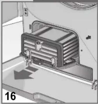
Interior view of a vehicle showing a mounted air vent or vent system with directional arrows indicating flow or movement (no text or symbols present)▼ Rotate the 3 levers to the vertical position and remove the condenser (fi g. 16).
natural_image
Illustration of a hand holding a handheld device next to a cylindrical device with heat sinks, showing rotational motion (no text or symbols)
natural_image
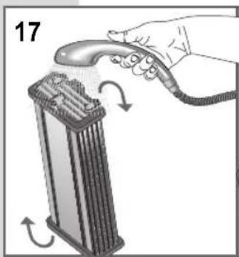
Illustration of a hand spraying a spray gun onto a metal tray (no text or symbols)▼ Wash the front, back and sides of the condenser, aiming the jet of water as shown (fi g.17/18).
To dry the condenser thoroughly, place it on its side on a towel.
When the condenser is dry, replace it following the same procedure in reverse order.
TROUBLESHOOTING
All electric appliances may break-down at some time.
Remember to call a qualified technician in these cases. However, many problems can be resolved without the need for external intervention.
Important: If a fault occurs, disconnect the appliance from the mains supply immediately.
Before calling the customer service centre, check the points listed below.
RESOLVING PROBLEMS
If the drier doesn't start
- Check that:
1) The appliance is plugged into the mains supply.
2) The mains socket is working correctly: 2a) The fuse has not blown. (Check by plugging in another appliance such as a table lamp and see if that works)
2b) All the instructions in the manual have been followed.
If the drier doesn't start
- Check that:
1) The door is closed properly
2) The start button has been pressed.
The washing does not dry
- Check that:
1) The air exhaust aperture is not blocked.
2) Clean fl uff fi Iter and condenser.
3) The filter is not blocked. (Remember that when the door is opened, the internal parts of the drier and the washing may be very hot).
If, after all these checks have been carried out, the appliance still does not work, inform the nearest customer service centre. When contacting the service centre, inform them of the appliance model, serial number and type of fault. This information will help the service centre operator in procuring the necessary spare parts, thus guaranteeing a speedy and effi cient repair.
Inside the product, an accessory is available to complete the installation and enable the drier to be mounted on top of a front-loading washing machine, thus saving space. If the drier is stacked on top of a washing machine the drier, the stacking kit HAS to be used. The installer will check if your washing machine is suitable for this type of installation.
STACKING KIT SAFETY
Your safety and that of others is extremely important.
This manual contains numerous recommendations and warnings for the safe use of this stacking system. We recommend that you read and follow these instructions carefully and comply with the mentioned safety warnings.

SAFETY WARNING SYMBOL
This symbol warns of potential hazards that may be life threatening for you and/or other persons. All the safety warnings are preceded by the safety warning symbol and the word “DANGER” or “WARNING”. These words have the following meaning:

DANGER: If this warning is NOT complied with immediately, the action may lead to serious injury or death.
DANGER: If this warning is NOT complied with, the action may lead to serious injury or death.
All the safety warnings supply precise information on the potential hazard, the methods to use for reducing the risk of accidents and the consequences of any non-compliance with the instructions given.

INSTALLATION INSTRUCTIONS
EQUIPMENT AND PARTS
17
A

natural_image
Technical line drawings of mechanical fasteners including fasteners, fasteners, and fasteners (no text or symbols)Before starting the installation, procure the required tools and parts.
Tools and equipment required
▼ TORX®† T20 screwdriver
▼ 24 mm spanner
▼ 2 corner pieces of expanded polystyrene taken from the packing material
▼ 1 soft cloth and water with a mild detergent added
Parts supplied (fi g.17)
Open the kit and check that all the parts are present.
A. Foot anchors
B. Brackets
C. B. C. TORX®† screws
TORX®† IS THE REGISTERED TRADEMARK OF TEXTRON INNOVATIONS INC.
BUILT-IN OR CUPBOARD INSTALLATION
IMPORTANT: The washing machine/drier stack can also be installed in a niche or cupboard. To this end, check the location of the water feed valves and earthed mains outlet socket. If any modifi cations are to be made to the water supply valves, mains sockets or power supply cable, ask the assistance service to carry out the work. The dimensions shown below refer to the minimum amount of space required.
An additional space should be left to facilitate the installation work and for maintenance purposes.
BUILT-IN OR CUPBOARD INSTALLATION

▼ Additional space may be required to compensate for the shape of walls, doors and fl oors (fi g. 18).

It is advisable to leave an additional space of 2.5 cm at the sides of the drier to reduce the transmission of vibration and noise (fi g. 19).
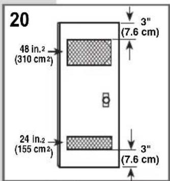
If the stack is to be installed in a single door cupboard, the top and bottom parts of the door should be provided with at least the minimum amount of ventilation (fi g. 20).
A louvred door with an equivalent number of ventilation openings can also be used (fi g. 20).
LEVELLING THE WASHING MACHINE
- With the help of 2 or more persons, move the washing machine as close as possible to its final installation location.
- Level the washing machine as described in the washing machine's instruction manual.

WARNING: Heavy weight. Use two or more persons to transport and install the washing machine.
NON COMPLIANCE WITH THIS WARNING MAY LEAD TO BACK INJURY OR OTHER.
FITTING THE STACKING BRACKETS
- Position the two expanded polystyrene corner pieces on the floor.
- With the help of two or more persons, grasp the body of the washing machine tightly and lower it face down onto the expanded polystyrene.

WARNING: Heavy weight. Use two or more persons to transport and install the drier.
NON COMPLIANCE WITH THIS WARNING MAY LEAD TO BACK INJURY OR OTHER.
FITTING THE STACKING BRACKETS
- Remove the two screws from the bottom of the drier and keep them (for vented drier models only).
- Fit the two brackets on the back edge of the washing machine, as shown (fi g. 22), using the two screws supplied with the kit.

natural_image
Line drawing of a rectangular mechanical component with mounting supports (no text or symbols)A. Remove the two screws (for vented drier models only fi g. 22).

B. Fix the brackets (fi g. 23/24).


- Use a 24 mm spanner to screw in the four feet of the drier as far as they will go and make contact with the bottom of the drier. Do not use excess force.
- Place the drier in the upright position.
- Use the soft cloth and water with added mild detergent to clean the top of the washing machine. This is to ensure that the adhesive foot supports supplied adhere properly to the surface.
INSTALLING THE DRIER ON TOP OF THE WASHING MACHINE
- With the help of 2 or more persons, lift the drier and place it on top of the washing machine.
Make sure that the stacking brackets are positioned away from the back edge of the washing machine.

WARNING: Heavy weight. Use two or more persons to transport and install the drier.
NON COMPLIANCE WITH THIS WARNING MAY LEAD TO BACK INJURY OR OTHER.
INSTALLING THE DRIER ON TOP OF THE WASHING MACHINE
natural_image
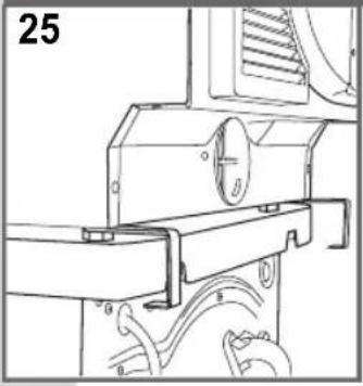
Technical line drawing of a mechanical assembly with no visible text or symbols- Slide the drier forwards towards the front of the washing machine.
The stacking brackets will slide over the back edge of the washing machine and into position (fi g. 25/26).

natural_image
Technical line drawing of a mechanical assembly with no visible text or symbols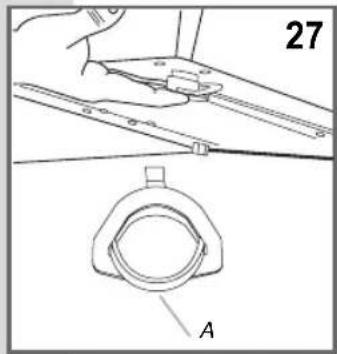
Anchoring the front feet of the drier
- Lean the drier backwards to lift the two front feet off the washing machine. Hold the drier in this position and fi t one of the foot anchors on one of the front feet of the drier. Refer to the fi gure alongside for the correct position of the foot anchor (fi g.27).
A. When the installation is complete, this edge should be visible from the front.
4. Remove the fi Im covering the adhesive on the bottom of the foot anchor.
IMPORTANT: The adhesive will stick immediately on contact. Consequently, make sure that the foot anchor is in the correct position before it makes contact with the washing machine. If the washing machine/drier stack is to be moved to another location in the future, the foot anchors should not be removed. Once removed, the foot anchors will no longer be able to adhere to the surface.
- Hold the foot anchor in position and replace the drier on top of the washing machine. The foot anchor will remain in the correct position, stuck to the top of the washing machine.
- Repeat the operation for the other front foot.
COMPLETING THE INSTALLATION
- Check that the two brackets on the back of the washing machine are firmly anchored in position. If there is any play in the brackets, use the 24 mm spanner to tighten the two back feet of the drier to make sure that the brackets are firmly anchored to the back edge of the washing machine.
- Lift the front of the drier and adjust the two front feet to the same height as the back feet.
- Place a level on the top of the drier to make sure it is sitting correctly. Check the level from one side to the other first, then from front to back.
If the washing machine and drier are not level, adjust the feet of the drier as necessary and repeat the level check.
- Bäste Kund,
- INNEHÅLLSFÖRTECKNING
- ANMÄRKNINGAR OCH RÅD FÖR ANVÄNDAREN 3-4
- ESKRIVNING AV MASKINEN 5
- STALLATION AV MASKINEN 5-7
- EXTRA TILLBEHÖR
- ÖPPNING OCH OMHÄNGNING AV LUCKA
- RENGÖRING OCH UNDERHÅLL
- FULLBORDA INSTALLATIONEN
- SÄHKÖVERKKOON LIITÄNTÄ
- LUUKUN AVAAMINENJA SUUNNAN VAIHTAMINEN
- LAUHDEVESISÄILIÖN TYHJENNYS
- PUHDISTUS JA HUOLTO
- EKSTRAUTSTYR
- KOPLE TIL DET ELEKTRISKE SYSTEMET
- ÅPNE OG OMHENGSLE DØREN
- FORHOLDSREGLER FOR T∅Y
- T∅RKING
- RENGJ∅RING OG VEDLIKEHOLD
- TILBEH∅R
- TILSLUTNING TIL STRÖMFORSYNINGEN
- ÅBNING OG ÆNDRING AF LÅGENS DREJNING
- RENG∅RING OG VEDLIGEHOLDELSE
- AFSLUTNING AF INSTALLATIONEN
- CONTENTS
- NOTES AND ADVICE FOR THE USER 59-61
- DESCRIPTION OF THE APPLIANCE 61
- INSTALLING THE APPLIANCE 61-63
- USING THE DRIER
- MAINTENANCE
- NOTES AND ADVICE FOR THE USER
- DESCRIPTION OF THE APPLIANCE
- OPTIONAL ACCESSORIES
- INSTALLING THE APPLIANCE
- INSTALLATION
- LEVELLING THE DRIER
- CONNECTING TO THE MAINS SUPPLY
- CONNECTING THE CONDENSATION DRAIN TO THE DRAINAGE SYSTEM
- OPENING THE DOOR AND CHANGING THE OPENING DIRECTION
- PRECAUTIONS FOR FABRIC TYPES
- RECOMMENDATIONS PRIOR TO DRYING
- SORTING THE WASHING
- If the label has no drying symbol, proceed as follows:
- General advice:
- Pure linen.
- 9
- PROGRAMME TABLE
- HOW TO DRY
- INTERNAL LIGHT (AVAILABLE ACCORDING TO MODEL)
- DRAINING THE CONDENSATION WATER RESERVOIR
- To empty the reservoir, proceed as follows:
- CLEANING AND MAINTENANCE
- TROUBLESHOOTING
- RESOLVING PROBLEMS
- If the drier doesn't start
- The washing does not dry
- STACKING KIT SAFETY
- Your safety and that of others is extremely important.
- SAFETY WARNING SYMBOL
- INSTALLATION INSTRUCTIONS
- EQUIPMENT AND PARTS
- Tools and equipment required
- BUILT-IN OR CUPBOARD INSTALLATION
- LEVELLING THE WASHING MACHINE
- FITTING THE STACKING BRACKETS
- INSTALLING THE DRIER ON TOP OF THE WASHING MACHINE
- Anchoring the front feet of the drier
- COMPLETING THE INSTALLATION
Brand : UPO
Model : TC7060D
Category : Tumble dryer