
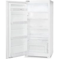
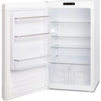
PRIMA-BOX - Refrigerator GRAM - Free user manual and instructions
Find the device manual for free PRIMA-BOX GRAM in PDF.
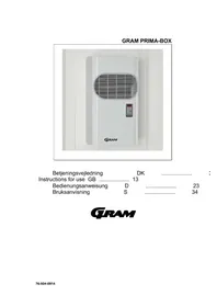


| Product Type | Fridge-Freezer |
| Brand | Gram |
| Model | PRIMA-BOX |
| Total Capacity | 250 L |
| Fridge Capacity | 180 L |
| Freezer Capacity | 70 L |
| Climate Class | SN-T (10°C - 43°C) |
| Noise Level | 40 dB(A) |
| Energy Class | E |
| Annual Energy Consumption | 220 kWh |
| Dimensions (H x W x D) | 1650 x 600 x 650 mm |
| Weight | 55 kg |
| Power Supply | 220-240 V, 50 Hz |
| Defrost Function | Automatic (fridge) / Manual (freezer) |
| Interior Light | LED |
| Shelves | 4 adjustable glass shelves |
| Crisper Drawer | 1 humidity-controlled drawer |
| Freezer Compartments | 3 drawers |
| Refrigerant | R600a (isobutane) |
| Warranty | 2 years |
| Accessories Included | Ice cube tray, egg tray |
| Maintenance & Cleaning | Clean with warm water and mild detergent; avoid abrasive cleaners |
| Safety Features | Child lock on freezer door, temperature alarm |
Frequently Asked Questions - PRIMA-BOX GRAM
User questions about PRIMA-BOX GRAM
0 question about this device. Answer the ones you know or ask your own.
Ask a new question about this device
Download the instructions for your Refrigerator in PDF format for free! Find your manual PRIMA-BOX - GRAM and take your electronic device back in hand. On this page are published all the documents necessary for the use of your device. PRIMA-BOX by GRAM.
USER MANUAL PRIMA-BOX GRAM
Operating instructions DK 3 Instructions for use GB 13 Operating instructions D 23 Operating instructions S 34
GRAM
DK
Table of contents
Description 2
Operating principle 2
Installation 2
Operating principle 2
Installation 2
Mounting of unit on the coldroom 3
Fitting remote panel 5
Electrical connection 5
Water connection 6
Pre start-up checks 6
Description of display panel 7
Setting room temperature 8
Alarms 9
Commissioning 10
Troubleshooting 10
Routine maintenance 11
Warnings 11
D
Contents
Fig. 4
| Mod. | Beskrivelse | Bestillingsnr. | Ant. |
| GM1 | Selvskærende skruer | 4 | |
| GM2 | AB 4,8x22 | 3VTE049 | 6 |
| GM3 | UNI 6954-71 | 6 |
INSTALLATION OF REMOTE CONTROL PANEL (optional)


Please read this booklet carefully.
It has been produced to provide details and advice on the correct method of installing and using this unit so as to maximise reliability, efficiency and long life.
DESCRIPTION
The GM units are a series of air cooled (water cooled available as an option) condensing units built on the monoblock principle. They consist of:
- condensing unit (on outside of cold room)
- evaporating unit (on inside of cold room)
- control panel, fitted to condensing unit
OPERATING PRINCIPLE
The GM series are refrigeration units incorporating hermetic compressors powered by electrical mains supply (single or three phase) and using HFC or HCFC refrigerant. The refrigerant is pumped through the evaporator inside the room where it absorbs heat thereby cooling the cold room. The refrigerant then passes to the condenser where the absorbed heat is dissipated into the ambient air giving back its refrigerating capacity. The cycle is then repeated.
There is also an automatic defrosting phase which is pre-programmed but adjustable by the user. Its frequency is cyclic.
INSTALLATION
For a correct installation please read:
3.1 Mounting of unit on the cold room 3.2 Fitting remote panel (optional)
3.3 Electrical connection
3.4 Water connection (in the case of a water cooled condenser)
In order to obtain optimum functioning of the unit ensure the following:-
A) Position the unit in a well ventilated location and away from other heat sources B) Limit the number of door openings C) Ensure the unit has a good fresh air supply to the suction side (front) and a good removal of air from the discharge side (top) D) Fit a drain line to the defrost water drain connection inside the condensing unit
N.B. For GM 1-2-3 models fitted with automatic evaporation of defrost water this is just a precaution in case of overflow.
Straddle version
Before mounting the unit, it is necessary to make the cuts and holes as per fig. 1. Fix the unit in place with the appropriate screws (fig. 4)

Fig. 1
| A | B | C | D | E | F | |
| mm | mm | mm | mm | mm | a° | |
| GM1 | 19 | 316 | 288 | 83 | 43 | 6 |
| GM2 | 19 | 316 | 503 | 83 | 43 | 6 |
| GM3 | 19 | 425 | 503 | 83 | 43 | 6 |

Having positioned the unit on the cold room, complete the connection between the evaporator drain tray spigot and the hole prepared on the cold room wall using the supplied fitting. Secure the fitting using the appropriate screws.
Thru-wall version (optional)
A) Prepare the hole in the cold room wall - see fig. 3. B) Position the unit onto the cold room wall inserting the evaporator section through the prepared hole. C) Fix unit to wall using the supplied screws - see fig. 4


Fig.3
| Mod. | A | B | C | D | E | F | G | H |
| GM1 | 735 | 264 | 280 | 110 | 400 | 335 | 373 | 100 |
| GM2 | 830 | 264 | 280 | 110 | 400 | 335 | 590 | 100 |
| GM3 | 830 | 364 | 350 | 110 | 522 | 440 | 590 | 100 |

Fig.4
| Mod. | Description | Code | Qty. |
| GM1 Self tapping screws | 4 | ||
| GM2 | AB 4,8x22 | 3VTE049 | 6 |
| GM3 | UNI 6954-71 | 6 | |
FITTING REMOTE PANEL (optional)


a) Remove side screws and lift off front cover. b) Fix back plate to wall using pre drilled holes taking care to keep panel in a vertical position c) Replace front cover (operation (a) reversed) d) Run interconnecting cable back to main panel taking care not to bundle it with other system cables
WARNING : Max. distance for remote panel cable is 10 m; for longer distances a "long distance" module (optional) must be used.
ELECTRICAL CONNECTION
To ensure correct electrical connection proceed as follows :-
1) Ensure that the mains supply voltage corresponds to the voltage indicated on the serial number plate. Acceptable tolerance is +/-10% of the nominal voltage. 2) Connection to the mains supply should be made using a residual current circuit breaker and by a qualified technician. 3) The use of a door microswitch (not supplied) on the coldroom door is recommended. It will automatically enable the following on each door opening:- -lighting of room lamp, unit stop -exclusion of temperature alarm (for 1 hour after door closure) 4) To access the electrical panel, it is necessary to remove the unit front cover (fig. 7).

Cable Glands Identification:
(A) For mains supply cable (B) For door heater supply (BGM only), alarm cable and door microswitch (optional)
Optional:
(C) Cable gland for remote panel cable
WATER CONNECTION
This connection is necessary only if the unit has a water cooled condenser. It should follow the tags positioned by the inlet and outlet pipes. Connection pipes should never be smaller in diameter than those on the unit. Minimum water pressure of 1 Bar is required for correct functioning of the machine.
PRE START UP CHECKS
Before turning unit ON please check the following:
- that the fixing screws are tight
- that the electrical connections have been correctly done In the event that the unit has been opened:-
- that no tools were inadvertently left inside
- that installation has been properly carried out
- that there are no gas leaks
- that the front cover has been correctly repositioned
DESCRIPTION OF DISPLAY PANEL


1) Control LED (Green):
LIT: Compressor running, unit is refrigerating
FLASHING: Compressor is in start delay mode ( waiting for signal to start )
OFF: Compressor is OFF. Room is down to set temperature.

2) Control LED (Green):
LIT: Evaporator fan(s) running.
FLASHING: Evaporator fan(s) in start delay mode (waiting for signal to start)
OFF: Evaporator fan(s) OFF.

3) Control LED (Yellow):
LIT: Unit is in defrost mode (auto or manual)

4) Alarm LED (Red):
LIT: Alarm is active - see separate ALARMS section
OFF: Unit is functioning normally.

5) Display: When connected to the mains the display will read OFF indicating condition of the unit. By pressing the ON/OFF key for 3 seconds the unit turn ON and display the room temperature. During programming mode various parameters will be displayed and during alarm mode an alarm le will be displayed.

6) SET/ESC key: Pressed for 3 seconds, the led is lit and setting of required room temperature is enabled. During programming it is used to pass from a sub menu to an upper one.

7) DOWN/ ROOM LIGHT key: During programming mode or setting of room temperature it serves to reduce the displayed value. At other times it serves to control the room light.

8) Defrost/UP key: By pressing for more than 4 seconds it activates a manual defrost. During programming mode or setting of room temperature it serves to increase the displayed value.

9) ON/OFF key: To turn ON or OFF the unit hold pressed for more than 3 seconds.

10) ENTER key: Permits access to programming menu and passage to the sub menu. It is advisable not to enter programming mode except in case of necessity and in the presence of a qualified technician.
SETTING ROOM TEMPERATURE
Programming room temperature:
- Connect unit to mains power. The display reads OFF.
To set the desired room temperature press the SET (6) key for more than 3 seconds. The green led will light and the previous set temperature will be displayed. To change the value press:

(8) to increase temperature

(7) to decrease temperature
Press the SET key or wait 5 seconds to return to the actual room temperature.
The following table shows the factory set limits to room temperature settings.
| Min. value Max. value | ||
| M range (Media temperatura) -5°C | +10° | |
| B range (Bassa temperatura) -25° | -15°C |
ALARMS
When an alarm condition occurs the unit will display an alarm code ( different according to the nature of the alarm ):
- alarm led will be lit (4)
- buzzer will sound
- alarm relay ( for remote alarm ) will be activated
The buzzer and alarm relay can be muted by pressing any key. When a key is pressed, the alarm led will flash for as long as the alarm condition persists.
To display the alarm code it is necessary to enter into the alarm menu:
Press ENTER key (10) for more than 3 seconds. FnC will be displayed. Press the DEFROST/UP key (8) until AL is displayed and then press ENTER (10). At this point the alarm code will be displayed indicating the nature of the alarm.
High Temperature Alarm (HI)
The red led, buzzer and remote alarm relay are activated; the alarm code HI is displayed in the alarm menu as indicated above. The causes can be:
- product too warm
- excessive door openings
- excessive product load
- unit malfunction
Low Temperature Alarm ( LI )
The red led, buzzer and remote alarm relay are activated; the alarm code LI is displayed in the alarm menu as indicated above. The causes can be:
- malfunction of the electronic controller
High Pressure Alarm (EO)
Each time the high pressure switch trips, the buzzer and red led are activated. If more than 10 trips occur during a 1 hour period then the unit will turn OFF automatically. The remote alarm relay will be activated and the label Err will flash on the display alternating with the room temperature.; the alarm code EO is displayed in the alarm menu as indicated above. To reset the unit it is necessary to turn the unit off, wait a few seconds and then turn it on again using the ON/OFF key (9). The causes can be:
- dirty condenser
- condenser fan fault
- front cover is removed
- obstructed condenser air intake or outlet
- lack of ventilation
Voltage Monitor Alarm (E8 - only when fitted as an option)
The optional voltage monitor is an electronic device which checks the unit's electrical supply. Should the voltage vary by +/- 12% then it will turn off and wait 6 minutes before attempting to re-start automatically - if the voltage has returned within limits. The red LED, buzzer and remote alarm relay are activated; the label Err will flash on the display alternating with the room temperature. The alarm code E8 is displayed in the alarm menu as indicated above.
WARNING: On first starting, the monitor has a time count of 7 minutes. It is important to leave the unit connected to the mains but in the OFF condition for the duration of the count.
Room Sensor Fault (E1)
The red LED, buzzer and remote alarm relay are activated; the label Err will flash on the display alternating with the alarm code E1. Possible causes are:
- faulty room sensor
- badly connected room sensor
Defrost Sensor Fault (E2)
The red LED, buzzer and remote alarm relay are activated; the label Err will flash on the display alternating with the room temperature. The alarm code E2 is displayed in the alarm menu as indicated above. Possible causes are:
- faulty defrost sensor
- badly connected defrost sensor
Condenser Sensor Fault (E4)
The red LED, buzzer, and remote alarm relay are activated; the label Err will flash on the display alternating with the room temperature. The alarm code E4 is displayed in the alarm menu as indicated above.
Possible causes are: - faulty condenser sensor - badly connected condenser sensor
Condenser Temperature Alarm (H4)
If the condensing temperature exceeds a factory preset value, the red LED and buzzer are activated. The alarm code H4 is displayed in the alarm menu as indicated above. Possible causes are:
- dirty condenser
COMMISSIONING
Having made the pre-start-up checks as described in section 4, connect to the mains supply. The display will be lit and OFF appears on the screen.
If the unit has a preheating cycle, it is necessary to keep it in this condition for at least 3 hours.
If the unit has a voltage monitor, it is necessary to keep it in this condition for at least 7 minutes.
Set the required room temperature as described in para. 5.1 above. Turn the unit ON using the ON/OFF key (9).
TROUBLESHOOTING
1) Compressor stops. There is an internal over-temperature device which stops the compressor each time the admissible temperature of the motor windings is exceeded. Possible causes are:
- insufficient ventilation to unit
- mains voltage anomaly
- faulty condenser fan motor. The device resets itself automatically when the windings cool down.
2) Formation of ice on evaporator coil impeding regular air flow. Possible causes are:
- excessive door openings/door left open for long periods
- - faulty running of evaporator fans
- - faulty bypass solenoid valve (models with hot gas defrost only)
- - faulty defrost heater (models with electric defrost only)
- - pre-set defrost routine not sufficient to effect full defrost. In this case it is possible to make some modifications:
- - increase the defrost termination temperature by a few degrees
- - decrease the time interval between defrosts (i.e., increase number of defrosts) - modifications to be made by your installer.
3) Display does not light. Check:
- - there is power to the unit
- - correct connection of mains cable
- - fuses inside electrical panel
4) If display lights but when ON/OFF key is pressed (for 3 seconds) unit does not turn ON: check correct connection of the door micro switch, remembering that the switch contact must be closed when door is closed.
ROUTINE MAINTENANCE
In order to keep the unit operating reliably and efficiently, it is necessary to periodically clean the condenser. (The frequency depends on the location in which the unit is installed.) This operation is to be done with the mains turned OFF. We advise use of an air jet blowing from the inside towards the outside. If an air jet is not available, then use a soft long-haired brush on the outside of the condenser, taking care not to damage the condenser fins. WARNING: condenser fins have sharp edges. For water-cooled condensers, it is advisable to use the services of a plumber who can clean the condenser with appropriate commercially available descaling solutions.
WARNINGS
Installation and repair is to be carried out by authorised personnel only.
Whenever it is necessary to make any maintenance operation to the unit it is a must to:
a) Stop the unit by pressing the ON/OFF key. b) Remove power to the unit by turning off the mains magneto-thermic isolator which has to be fitted to the units' power supply.
Whenever removing the units' cover be careful of the pipes which can be very hot or very cold.
No type of refrigerant must be vented into the atmosphere. Only charge unit with the same refrigerant as indicated on the serial no. plate.

Fig. 4

Room sensor defective (E1)
Cooling sensor defective (E4)
2 The Technology Centre
London Road, Swanley
Kent BR8 7AG
Tel.: 1322-616900

Gram Commercial A/S
6500 Vojens - Denmark
Tlf.: +45 73 20 12 00
- DK
- TABLE OF CONTENTS
- D
- CONTENTS
- INSTALLATION OF REMOTE CONTROL PANEL (OPTIONAL)
- DESCRIPTION
- OPERATING PRINCIPLE
- INSTALLATION
- THRU-WALL VERSION (OPTIONAL)
- FITTING REMOTE PANEL (OPTIONAL)
- ELECTRICAL CONNECTION
- WATER CONNECTION
- PRE START UP CHECKS
- DESCRIPTION OF DISPLAY PANEL
- SETTING ROOM TEMPERATURE
- ALARMS
- HIGH TEMPERATURE ALARM (HI)
- LOW TEMPERATURE ALARM ( LI )
- HIGH PRESSURE ALARM (EO)
- VOLTAGE MONITOR ALARM (E8 - ONLY WHEN FITTED AS AN OPTION)
- ROOM SENSOR FAULT (E1)
- DEFROST SENSOR FAULT (E2)
- CONDENSER SENSOR FAULT (E4)
- CONDENSER TEMPERATURE ALARM (H4)
- COMMISSIONING
- TROUBLESHOOTING
- ROUTINE MAINTENANCE
- WARNINGS
- ROOM SENSOR DEFECTIVE (E1)
- COOLING SENSOR DEFECTIVE (E4)
Brand : GRAM
Model : PRIMA-BOX
Category : Refrigerator