
DUR-801 - Barcode Reader Deltaco - Free user manual and instructions
Find the device manual for free DUR-801 Deltaco in PDF.


| Product Type | Barcode Reader |
| Brand | Deltaco |
| Model | DUR-801 |
| Connectivity | USB wired |
| Scan Technology | Laser or CCD (estimated) |
| Supported Barcodes | 1D barcodes (UPC, EAN, Code 39, Code 128, etc.) |
| Scan Rate | Up to 200 scans per second (typical) |
| Reading Distance | 2 to 20 cm (typical) |
| Dimensions (W x D x H) | Approximately 17 x 9 x 7 cm |
| Weight | Approximately 150 g |
| Power Supply | Via USB port (5V DC, 100 mA) |
| Cable Length | 1.5 m (typical) |
| Operating Temperature | 0°C to 40°C |
| Storage Temperature | -20°C to 60°C |
| Humidity | 5% to 95% non-condensing |
| Drop Resistance | 1.5 m onto concrete (typical) |
| Compatibility | Windows, macOS, Linux |
| LED Indicators | Power and scan status |
| Beeper | Configurable audible feedback |
| Cleaning and Maintenance | Wipe with dry cloth; avoid liquids |
| Safety | CE, FCC certified |
| Parts and Repairability | No user-replaceable parts; contact support |
| Included Accessories | USB cable, user manual |
Frequently Asked Questions - DUR-801 Deltaco
User questions about DUR-801 Deltaco
0 question about this device. Answer the ones you know or ask your own.
Ask a new question about this device
Download the instructions for your Barcode Reader in PDF format for free! Find your manual DUR-801 - Deltaco and take your electronic device back in hand. On this page are published all the documents necessary for the use of your device. DUR-801 by Deltaco.
USER MANUAL DUR-801 Deltaco
Setup Flow Chart ....4
Group 0 : Interface Selection....5
Group 1 : Device Selection for keyboard Interface....6-7
Group 2 : Inter-character Delay....8
Group 3 : Language for Keyboard Interface... 9-10
Group 4 : Terminator....11-12
Group 5 : Scan Mode....13-14
Group 6 : Preamble and Postamble....15
Group 7 : RS-232 Parameters... 16-18.....
Group 8 : Code 39 / Code 32... 19-20.....
Group 9-1 : Interleaved 2 of 5... 1 ....2
Group 9-2 : Industrial 2 of 5 / IATA... 22......
Group 9-3 : Matrix 2 of 5. 23....
Group 9-4 : China Postage. 24....
Group 10 : Code 128.25......
Group 11 : Code 11. 26.
Group 12 : Code 93. 27.
Group 13 : MSI-PLESSY. 28
Group 14 : Codabar/NW7. 29
Group 15 : Code 4. 30.
Group 16-1 : EAN-13/JAN-13. ....31
Group 16-2 : UPC-A .....32
Group 16-3 : EAN-8/JAN-8....33
Group 16-4 : UPC-E....34
Group 16-5 : ISBN/ISSN....35
Group 17 : General Parameter. .....36.
Group 18 : Code ID Setting. ....37.
Group 19: Wand Type Parameters. ....38
Group 20-1 : Magnetic Parameters....39-40
Group 20-2 : Magnetic Parameters....41
Group 21 : Function Key Emulation. .....2.4
Function Code for PC XT/AT.... 43-44
Table-Hex :Hexadecimal...45....
ASCII Table.... 46
Hexadecimal-Decimal Conversion Table...... 47
Pin Assignments 48-50
Getting Started
Installing Keyboard Wedge Scanner
To install a keyboard wedge scanner, follow the steps listed below:
1) Make sure that the scanner has the correct Y (U)-cable for the system (a PC or terminal)
2) Turn off the power of the system
3) Unplug the keyboard from the system
4) Connect the Y (U)- cable to the system and keyboard
5) Turn on the power of the system
6) If the indicator LED lights up and the buzzer sounds, the scanner is ready for reading
Installing a RS-232 Interface Scanner
To install a RS-232 interface scanner, the host device should have a RS-232 port to receive data from the scanner, follow the steps listed below:
1) Make sure that the scanner has the right connector for the RS-232 port of the host device
2) Make sure that there is a power supply to the scanner (if necessary)
3) Connect the cable to the RS-232 port of the device
4) If the indicator LED lights up and the buzzer sounds, the scanner is ready for reading
Note: The installation and setting up procedures of a USB interface scanner are the same as those of a keyboard wedge scanner.
Setup Procedures
1) Locate a group that contains the parameters to be changed.
2) Scan the "Enter Group #" label. The scanner will sound beeps indicate that setup is in progress
3) Scan the label representing the parameter to be changed
4) Scan the "Exit" to end the group currently selected, the scanner will sound beeps
5) Repeat the procedure for other groups including the parameters to be changed
Example 1:
Set the operating mode to "Continuous mode"
1) Scan "Enter Group 5"
2) Scan "Continuous/Trigger off"
3) Scan "Exit"
Example 2
Assign Preamble string as "#", and postamble string as "END"
1) Scan "Enter Group 6"
2) Scan Preamble
3) Scan "#" from "Full ASCII Table and Table-Hex."
4) Scan "Confirm" Label in Table-Hex
5) Scan "Postamble"
6) Scan "E", "N", "D" from "Full ASCII Table and Table Hex" consecutively
7) Scan "Confirm" Label in Table-Hex.
8) Scan Exit
Setup Flow Chart
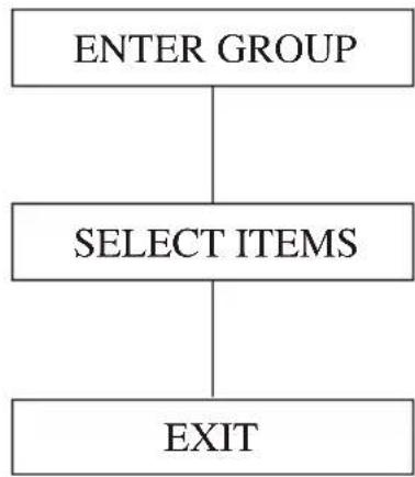
flowchart
graph TD
    A["ENTER GROUP"] --> B["SELECT ITEMS"]
    B --> C["EXIT"]

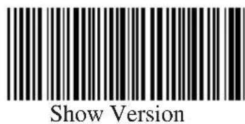
Note: (*) denotes default setting options marked by () only available upon request.are
Group 0: Interface Selection

ENTER GROUP

EXIT

KEYBOARD

RS-232

(WAND)

(OCIA)

(DTMF)
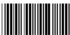
Reserved 2

Resered 3

Reserved 4
Note: The interface is pre-set at factory according to the model of the device.
Group 1: Device Selection for Keyboard Interface

ENTER GROUP
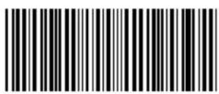
EXIT

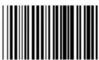
PC/AT, PS/2 50,60,70,80(*)
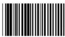
PC/XT

PS/2 25, 30

(NEC 9801)
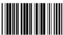
(IBM 5550)
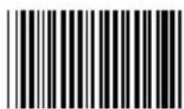
(PS 55)

(NEC N5520)
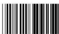
(ACER 7300)

(KW105D/

(WANG 5425)
CT-700A/WANG 5120)
(MAC_SE)

(LC-6533)
Note: Options marked by ( ) are only available upon request.
Group 1: Device Selection for Keyboard Interface
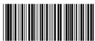
ENTER GROUP

EXIT

(IBM3196, 3197, 3476, 3477)

Reserved R

Reserved Q

IBM3197

Reserved T

IBM3477

IBM 3476

Reserved 6
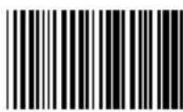
5Reserved

Reserved 8

7Reserved

9Reserved
Group 2: Intercharacter Delay

ENTER GROUP

EXIT
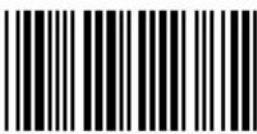
Start Keyboard Setting
Scan Enter Group 2 Label -- >
Scan Start Keyboard (or RS-232) Setting Label -->
Scan two digits labels in Table-Hex -->
Scan Exit Label

Start RS-232 Setting
Keyboard Default Value: 05
RS-232 Default Value : 00
Group 3: Language for Keyboard Interface

ENTER GROUP

EXIT

U.S. (*)

ENGLAND
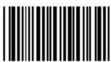
FRANCE

GERMANY

ITALY

BELGIUM

SWEDEN/FINLAND

SPANISH
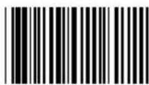
DENMARK

PORTUGAL

SWISS

NORWAY
Group 3: Language for Keyboard Interface

ENTER GROUP

EXIT

CANADA

HOLLAND

POLAND

LATIN
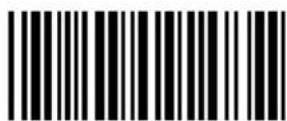
JAPAN

1Reserved

2Reserved

3Reserved

(IBM THINK-PAD FOR JAPAN)

(PANASONIC CF-II FOR JAPAN)
Note: Options marked by ( ) are only available upon request.
Group 4: Terminator
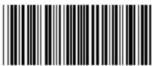
ENTER GROUP

EXIT
KEYBOARD
NONE
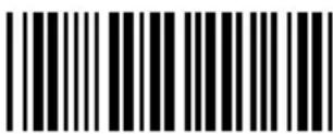
CR

(*)
SPACE

TAB
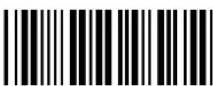
ESC
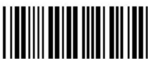
CTRL-C

EXEC

Group 4: Terminator

ENTER GROUP

EXIT
RS-232
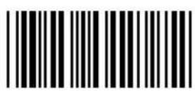
NONE

CR (*)

CR/LF

LF
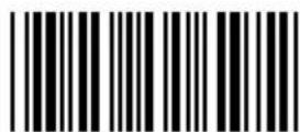
SPACE

TAB

ESC

CTRL-C

STX..ETX

XON.. XOFF

EOT
Group 5: Scan Mode
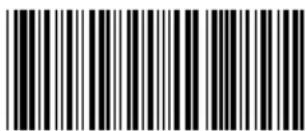
ENTER GROUP
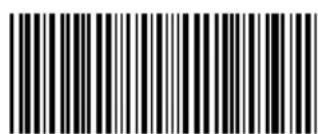
EXIT

1: Trigger On/Off
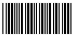
2: Trigger On/ Good Read Off (*)

3: Trigger On/
Good Read Off/
Delay Timeout = ?
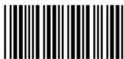
4: Continuous/Trigger Off

5: Continuous/
LED Always on
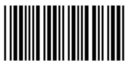
6: Continuous/No Trigger

7: Continuous/Testing

8: Continuous/
Trigger Off/
Delay Timeout = ?
Delay Timeout Setting:
Scan Enter Group 5 Label --> Scan 3 or 8 Label --> Scan two digit labels in Table-Hex --> Scan Confirm Label in Table-Hex --> Scan Exit Label
Note: Scan mode setting is only available for CCD/LASER type scanner. Setting wand type scanner to this mode will cause the scanner to break down.
Group 5: Scan Mode

ENTER GROUP

EXIT

FLASH OFF(*)

FLASH ON
Note: Scan mode setting is only available for
Laser type scanner.CCD/
Group 6: Preamble and Postamble
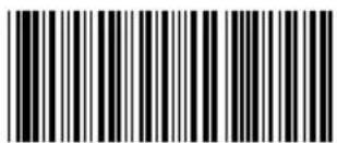
ENTER GROUP

EXIT

Preamble

Postamble
Preamble & Postamble Setting:
Scan Enter Group 6 Label -->
Scan Preamble or Postamble Label -->
Refer to ASCII Table(page 46), scan two digits in Table-Hex (Page 45)
Representing one character, maximum 10 characters can be accepted. -->
Scan Confirm Label in Table-Hex (Page 45)
Scan Exit Label

Clear
Clear Preamble & Postamble :
Scan Enter Group 6 Label -->
Scan Preamble or Postamble Label -->
Scan Clear Label-->
Scan Exit Label
Group 7: RS-232 Parameters

ENTER GROUP
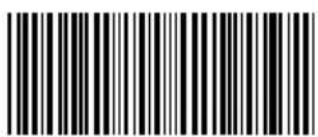
EXIT
Baud Rate

600
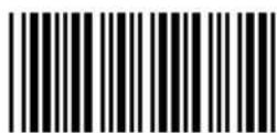
1200

2400

4800

9600(*)
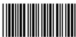
19200

38400
Data Bit

BIT 7

BIT 8 (*)
Group 7: RS-232 Parameters

ENTER GROUP

EXIT
Parity :

NONE (*)

ODD

EVEN
Handshaking:

NONE (*)

XON/XOFF

Scanner Ready

Data Ready

ACK/NAK
Group 7: RS-232 Parameters

ENTER GROUP

EXIT
(ACK/NAK Response Time CTS Observation Time:)

100 ms

300 ms

500 ms

1 sec

3 sec (*)

5 sec

10 sec

00
Group 8: CODE 39 / CODE 32

ENTER GROUP

EXIT
Code 39

Disable
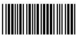
Enable (*)
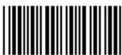
Full ASCII

Standard (*)
Transmit Start/End Character

Enable

Disable (*)
Transmit Check Character
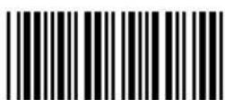
Enable (*)
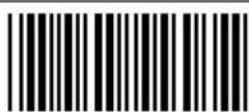
Disable
Verify Checksum

Disable (*)

Enable
Group 8: CODE 39 / CODE 32






Group 9-1: Interleaved 2 OF 5
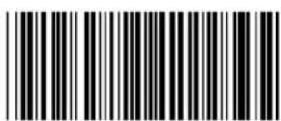
ENTER GROUP

EXIT

Enable (*)

Disable
Transmit Check Character
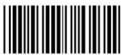
Enable (*)
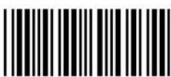
Disable
Verify Checksum

Enable

Disable (*)

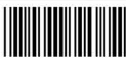
Barcode Length Setting:
Scan Enter Group 9-1 Label -->
Scan Length Define Label -->
Scan Four Digit Labels in Table Hex (Page 45) -->
Scan Confirm Label in Table-Hex -->
Scan Exit Label
Length Define
Min: 4
Max: 48
User Define Length Setting:
Scan Enter Group 9-1 Label
Scan User Define Label-->
Scan Six Digit Labels in Table Hex
(Only 3 sets of length can be defined)
Scan Confirm Label in Table Hex -->
Scan Exit Label
User Define
3 Sets Available
Group 9-2: Industrial 2 OF 5 / IATA

ENTER GROUP

EXIT

Enable (*)

Disable
Transmit Check Character

Enable (*)

Disable
Verify Checksum

Enable

Disable (*)

Barcode Length Setting:
Scan Enter Group 9-2 Label -->
Scan Length Define Label -->
Scan Four Digit Labels in Table Hex (Page 45) -->
Scan Confirm Label in Table-Hex -->
Scan Exit Label
Length Define
Min: 2
Max: 24

User Define Length Setting:
Scan Enter Group 9-2 Label
Scan User Define Label-->
Scan Six Digit Labels in Table Hex
(Only 3 sets of length can be defined)
Scan Confirm Label in Table Hex -->
Scan Exit Label
User Define
3 Sets Available
IATA

Enable

Disable (*)
Group 9-3: Matrix 2 OF 5
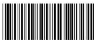
ENTER GROUP

EXIT

Enable (*)

Disable
Transmit Check Character

Enable (*)

Disable
Verify Checksum

Enable

Disable (*)
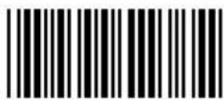
Barcode Length Setting:
Scan Enter Group 9-3 Label -->
Scan Length Define Label -->
Scan Four Digit Labels in Table Hex (Page 45) -->
Scan Confirm Label in Table-Hex -->
Scan Exit Label
Length Define
Min: 2
Max: 40
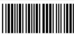
User Define Length Setting:
Scan Enter Group 9-3 Label
Scan User Define Label-->
Scan Six Digit Labels in Table Hex
(Only 3 sets of length can be defined)
Scan Confirm Label in Table Hex -->
Scan Exit Label
User Define
3 Sets Available
Group 9-4: CHINA POSTAGE

ENTER GROUP

EXIT

Enable (*)

Disable
Transmit Check Character
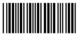
Enable (*)

Disable
Verify Checksum

Enable
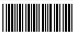
Disable (*)

Barcode Length Setting:
Scan Enter Group 9-4 Label -->
Scan Length Define Label -->
Scan Four Digit Labels in Table Hex (Page 45) -->
Scan Confirm Label in Table-Hex -->
Scan Exit Label
Length Define
Min: 2
Max: 40

User Define Length Setting:
Scan Enter Group 9-4 Label
Scan User Define Label-->
Scan Six Digit Labels in Table Hex
(Only 3 sets of length can be defined)
Scan Confirm Label in Table Hex -->
Scan Exit Label
User Define
3 Sets Available
Group 10: Code 128

ENTER GROUP

EXIT
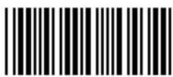
Enable (*)

Disable
Enable/Disable Checkdigit

Enable (*)
(not send checkdigit)

Disable
UCC/EAN/128

Enable

Disable (*)
GTIN

Enable

Disable (*)
Note: Options marked by ( ) are only available upon request
Group 11: CODE 11

ENTER GROUP
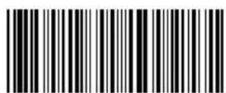
EXIT

Enable (*)

Disable
Number of Check Character
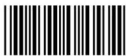
Two (*)

One
Transmit Check Character

Enable (*)

Disable
Enable/Disable Checkdigit

Enable (*)

Disable
Group 12: Code 93

ENTER GROUP

EXIT

Enable (*)

Disable
Verify Checkdigit

Disable

Enable (*)
Group 13: MSI-PLESSEY

ENTER GROUP

EXIT
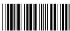
Enable (*)

Disable
Verify Checkdigit
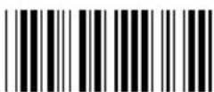
Enable (*)

Disable
Enable MOD

Enable MOD 10-10

Enable MOD 10 (*)

Enable MOD 11-10
Transmit/Truncate Checkdigit

Truncate 1 ^st checkdigit
ENTER GROUP
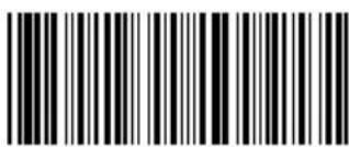
EXIT

Enable (*)

Disable
Transmit Start/End Character

Enable

Disable (*)
Start/End Transmit Type

ABCD/ABCD

ABCD/TN*E
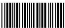
abcd/abcd (*)

abcd/tn*e
Group 15: Code 4
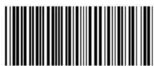
ENTER GROUP
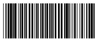
EXIT
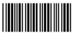
Enable (*)

Disable
Group 16-1: EAN-13/JAN-13

ENTER GROUP

EXIT

Enable (*)

Disable
ADD-ON 2/5

Enable

Disable (*)
Transmit Check Character

Enable (*)
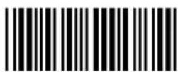
Disable
Truncate 1 ^st digit

Enable

Disable (*)
Truncate 2 ^nd digit

Enable

Disable (*)
EAN Checkdigit
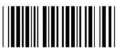
Enable (*)

Disable
Group 16-2: UPC-A
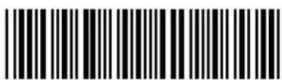
ENTER GROUP

EXIT

Enable (*)

Disable
ADD-ON 2/5

Enable

Disable (*)
Transmit Check Character

Enable (*)

Disable
Truncate Leading Digit

Enable

Disable (*)
UPC-A Convert to EAN-13

Enable

Disable (*)
Group 16-3: EAN-8/JAN-8

ENTER GROUP

EXIT

Enable (*)

Disable
ADD-ON 2/5

Enable
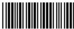
Disable (*)
Transmit Check Character
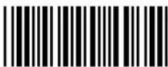
Enable (*)

Disable
Truncate Leading Digit

Enable

Disable (*)
EAN-8 Convert to EAN-13
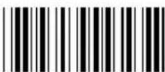
Enable 1
(add zeros in the front of barcode)

Disable (*)

Enable 2
(add zeros in the middle of barcode)
Group 16-4: UPC-E

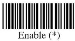

ADD-ON 2/5


Transmit Check Character
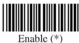

Truncate Leading Digit


UPC-E Convert to UPC-A


Group 16-5: ISBN/ISSN

ENTER GROUP

EXIT
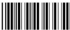
Disable (*)

Enable
Group 17: General Parameters

ENTER GROUP
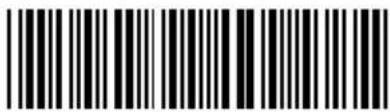
EXIT

Upper Case

Lower Case (*)

Universal

ALT Mode

Buzzer Pitch
(Default : 21)

Buzzer Duration
(Default: AA)
Buzzer Pitch & Buzzer Duration Setting:
Scan Enter Group 17 Label -->
Scan Buzzer Pitch or Buzzer Duration Label -->
Scan Two Digit Labels in Table-Hex -->
Scan Confirm Label in Table-Hex -->
Scan Exit Label
Power Up Beeping

Disable

Enable (*)

Normal

Turbo (*)
Group 18: Code ID Setting

ENTER GROUP

EXIT

CODE 39/CODE 32

INTERLEAVED 2 OF 5
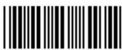
INDUSTRIAL 2 OF 5

MATRIX 2 OF 5

CHINA POSTAGE

CODE 128

CODE 93

CODE 11

MSI/PLESSEY

CODABAR/NW7

EAN-13

EAN-8

UPC-E
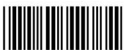
UPC-A

CODE 4
Note: Refer to ASCII Table, scan two hexadecimal labels in Table Hex to represent one character
Group 19: WAND Type Parameters
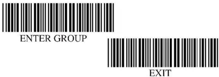
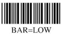

Scan Speed
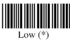


Data Format
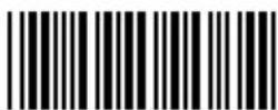
Transmit in Normal Format (*)


Transmit in Code 39 Format
Transmit in Code 128 Format
Group 20-1: (Magnetic Parameters)

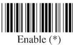

Track Order

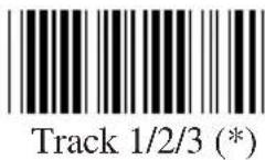




Group 20-1: (Magnetic Parameters)

Track Selection

Track 1 only

Track 1&2&3 any (*)

Track 3 only

Track 2 only

Track 2 and 3

Track 1 and 2

Track 1 and 2 and 3

ISO (*)

(JIS-2)
Note: Options marked by ( ) are only available upon request
Group 20-2: (Magnetic Parameters)

Start Sentinel: (SS)

Tk2 Default: ;
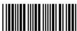
Tk1 Default : %

Tk3 Default: ;
End Sentinel: (ES)
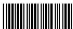
Tk1&2&3 Default: ?
DLE:

Tk2 Default: Null

Tk1 Default : Null

Tk3 Default: Null
STX:

Tk1&2&3 Default: Null
Magnetic Output Data Format:
STX - Tk1 Start Sentinel - Tk1 Data - End Sentinel - Tk1 - DLE
STX - Tk2 Start Sentinel - Tk2 Data - End Sentinel - Tk2 - DLE
STX - Tk3 Start Sentinel - Tk3 Data - End Sentinel - Tk3 - DLE
Note: Options marked by ( ) are only available upon request
Group 21: (Function Key Emulation)
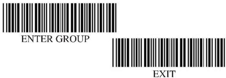

Enable
Enable Function Key Emulation:
Scan Enter Group 21 Label -->
Scan Enable Label -->
Scan Exit Label

Disable (*)
1:
To concatenate a function key with input data, please refer to Function Key Table for its hexadecimal representation.
For Example:
Preamble data with F1
Scan Enter Group 6 Label -->
Scan Preamble Label -->
Scan Label 0 and 1 respectively in Table-Hex (Page 45) -->
Scan Confirm Label in Table-Hex (page 45) -->
Scan Exit Label
| Function Key Table (Full ASCII Code 39 Table) | ||
| F1:01 F2:02 F3:03 F4:04 | ||
| F5:05 F6:06 F7:07 F8:08 | ||
| F9:09 F10:0A F11:0B F12:0C | ||
| Enter:0D Tab:0E BS:0F Up:10 | ||
| Down:11 Left:12 Home:14 End:15 | ||
| PgUp:16 PgDn:17 Ins:18 Del:19 | ||
| Esc:1B Right:13 S-Tab:1C | ||
2:
To scan a function key barcode label, Full ASCII must be enabled. Please refer to Full ASCII Code 39 Table to produce the function key barcode label.

Full ASCII Code 39 Enable
Function Code for PC XT/AT


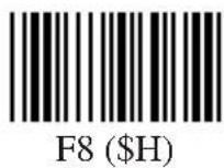


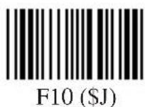


Function Code for PC XT/AT

Enter (\$M)

End (\U) (\B)

Tab (\$N)

PgUp (\$V)

BS (\$O)

PgDn (\$W)

Up (\$P)

Ins (\$X)

Down (\$Q)
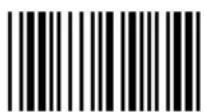
Del (\$Y)

Left (\$R)

Esc (\%A)

Right (\$S)

Home (\$T)
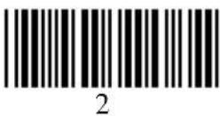
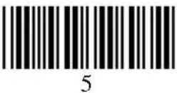
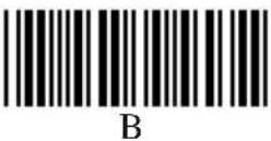
Table-Hex : HEXADECIMAL
 | |
 | |
 | |
 | |
 | |
 | |
 | |
 | |
 | |
 | |
 | |
 | |
 | |
 | |
 | |
 | |
 |
| L/H 01234567 | ||||||||
| 0 | NUL DLE SP 0 | 4 P、p | ||||||
| 1 | SCH | DCI | i | 1 | A | Q | a | g |
| 2 | STX | DC2 | " | 2 | B | R | b | r |
| 3 | ETX | DC3 | # | 3 | C | S | c | |
| 4 | EOT | DC4 | $ | 4 | D | T | d | t |
| 5 | ENQ | NAK | % | 5 | E | U | e | u |
| 6 | ACK | SYN | 8 | 6 | F | V | f | v |
| 7 | BEL | ETB | ' | 7 | G | W | g | w |
| 8 | BS | CAN | () | 8 | H | X | h | x |
| 9 | HT | EM | () | 9 | I | Y | ! | y |
| IA | SUB | ZJ: | z | |||||
| B | VT | ESC | + | ; | K | [ | k | { |
| C | EF | FS | . | < | L | \ | l | | |
| D | CR GS | - = | M [ m | { | ||||
| ESO RS . > N v n ~ | ||||||||
| F | SI | US | / | ? | O | - | o | DEL |
Hexadecimal-Decimal Conversion Table
| H/I | 10 | 234 | 5678 | 9AB | CDEF | |||||||||||
| 00 | 1234 | 5678 | 91011 | 12131415 | ||||||||||||
| 116 | 1718 | 192021 | 2223 | 24252627 | 2829 | 3031 | ||||||||||
| 2 | 32 | 33 | 34 | 35 | 36 | 37 | 38 | 39 | 40 | 41 | 42 | 43 | 44 | 45 | 46 | 47 |
| 3 | 48 | 49 | 50 | 51 | 52 | 53 | 54 | 55 | 56 | 57 | 58 | 59 | 60 | 61 | 62 | 63 |
| 4 | 64 | 65 | 66 | 67 | 68 | 69 | 70 | 71 | 72 | 73 | 74 | 75 | 76 | 77 | 78 | 79 |
| 5 | 80 | 81 | 82 | 83 | 84 | 85 | 86 | 87 | 88 | 89 | 90 | 91 | 92 | 93 | 94 | 95 |
| 6 | 96 | 97 | 98 | 99 | 100 | 101 | 102 | 103 | 104 | 105 | 106 | 107 | 108 | 109 | 110 | 111 |
| 7 | 112 | 113 | 114 | 115 | 116 | 117 | 118 | 119 | 120 | 121 | 122 | 123 | 124 | 125 | 126 | 127 |
| 8 | 128 | 129 | 130 | 131 | 132 | 133 | 134 | 135 | 136 | 137 | 138 | 139 | 140 | 141 | 142 | 143 |
| 9 | 144 | 145 | 146 | 147 | 148 | 149 | 150 | 151 | 152 | 153 | 154 | 155 | 156 | 157 | 158 | 159 |
| A | 160 | 161 | 162 | 163 | 164 | 165 | 166 | 167 | 168 | 169 | 170 | 171 | 172 | 173 | 174 | 175 |
| B | 176 | 177 | 178 | 179 | 180 | 181 | 182 | 183 | 184 | 185 | 186 | 187 | 188 | 189 | 190 | 191 |
| C | 192 | 193 | 194 | 195 | 196 | 197 | 198 | 199 | 200 | 201 | 202 | 203 | 204 | 205 | 206 | 207 |
| D | 208 | 209 | 210 | 211 | 212 | 213 | 214 | 215 | 216 | 217 | 218 | 219 | 220 | 221 | 222 | 223 |
| E | 224 | 225 | 226 | 227 | 228 | 229 | 230 | 231 | 232 | 233 | 234 | 235 | 236 | 237 | 238 | 239 |
| F | 240 | 241 | 242 | 243 | 244 | 245 | 246 | 247 | 248 | 249 | 250 | 251 | 252 | 253 | 254 | 255 |
For Example:
Hexadecimal
56 -> H:5 L:3
D5-> H:D L:5
Decimal
83
213
PIN ASSIGNMENTS
10 Pin Modular Plug
| RJ-45 Male10P10C | TTL W | AND KB RS-232 KB USB | → | ||
| 1 | × | × | × | RTS | × |
| 2 | × | × | × | × | |
| 3 | × | × | × | ||
| 4 | |||||
| 5 | GOOD-READ | READ | DATA | × | DATA |
| 6 | DATA | DATA | PC-CLK | × | PC-CLK |
| 7 | VCC | VCC | VCC | VCC | VCC |
| 8 | KB-CLK × | × | × | ||
| 9 | S.O.S | × | KB-DATA | × | × |
| 10 | × | × | × | × | |
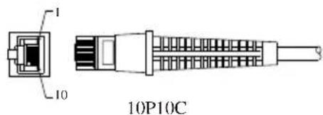
TTL Signal Output
| Function | DB9F | Din6M/5M(240°) |
| Start of Scan | 1 | 6 |
| Signal Data | 2 | 2 |
| Led Indicator | 3 | --- |
| Trigger | 5 | 5 |
| Power Enable | 6 | 4 |
| GND | 7 | 3 |
| VCC+5V | 9 | 1 |
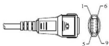
DB9F

Din6M
Din5M (without pin#6)
PIN ASSIGNMENTS
Wand Emulation Signal Output
| Function | DB9F | Din5M(180°) | Din6M/Din5M(240°) |
| Signal Data 2 | 2 | ||
| GND 7 2 3 | |||
| VCC+5V 9 3 1 |

DB9F
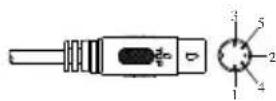
Din5M (180")
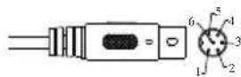
Din6M
Din5M (without pin#6)
Note : "F" stands for a female connector, while "M" stands for a male connector.
RS-232 Signal Output
| Function DB9F+DC (or without DC) | |
| GND 5 | |
| CTS 7 | |
| RTS 8 | |
| RX | 3 |
| TX | 2 |
| VCC+5V | 9 |
Note : For PC applications, a cable with DC power jack is required to accept external power input.

DB9F+DC -Jack
Keyboard Signal Output
| Funcion | Din5F | Din5M | Mini-Din6M | Mini-Din6F |
| GND 4 | 4 3 | 3 | ||
| PC_Data | --- 2 | 1 --- | ||
| PC_CLK | --- 1 | 5 --- | ||
| Vcc+5V | 5 5 | 4 4 | ||
| KB_CLK 1 | --- | --- 5 | ||
| KB_Data 2 | --- --- 1 |

USB Signal Output
| FUNCTION USB-A | |
| GND 4 | |
| Vcc | 1 |
| D+ | 3 |
| D- | 2 |

bar
| Category | Value | |---|---| | Bar 1 | 10 | | Bar 2 | 10 | | Bar 3 | 10 | | Bar 4 | 10 | | Bar 5 | 10 | | Bar 6 | 10 | | Bar 7 | 10 | | Bar 8 | 10 | | Bar 9 | 10 | | Bar 10 | 10 |

Brand : Deltaco
Model : DUR-801
Category : Barcode Reader