
FXMA200AXVMB - Uncategorized DAIKIN - Free user manual and instructions
Find the device manual for free FXMA200AXVMB DAIKIN in PDF.

| Product Type | VRV System Air Conditioner (Indoor Unit) |
| Model Series | FXMA50-125A5VEB (FXMA200AXVMB similar) |
| Refrigerant | R32 (Mildly Flammable, GWP 675) |
| Power Supply | 220-240 V ~ 50/60 Hz |
| Minimum Circuit Ampacity (MCA) | 1.8 A (FXMA50) to 3.2 A (FXMA125) |
| Recommended Circuit Breaker | 6 A |
| Operation Modes | Cooling, Heating, Fan Only, Auto, Defrost, Hot Start |
| Airflow Automatic Adjustment | Yes |
| External Static Pressure Setting | 0-200 Pa (via user interface) |
| Refrigerant Leakage Sensor | Yes (semiconductor type, lifetime 10 years) |
| User Interface Compatibility | Safety system compatible remote controller (e.g., BRC1H52/82*) |
| Installation Options | Rear suction or bottom suction; ducted or non-ducted |
| Drain Piping | VP25 (nominal) with 1/100 slope; rising piping ≤300 mm |
| Air Filter Cleaning Interval | Every 6 months (or when notification displays) |
| Sound Pressure Level | < 70 dBA |
| Safety Features | Fire alarm input (T1/T2), all-pole disconnection breaker, R32 leak detection |
| Environmental Compliance | EU/UKCA Declarations, EN/IEC 60335-2-40 |
| Repair and Maintenance | Authorized installer only; sensor replacement after detection or 10 years |
Frequently Asked Questions - FXMA200AXVMB DAIKIN
User questions about FXMA200AXVMB DAIKIN
0 question about this device. Answer the ones you know or ask your own.
Ask a new question about this device
Download the instructions for your Uncategorized in PDF format for free! Find your manual FXMA200AXVMB - DAIKIN and take your electronic device back in hand. On this page are published all the documents necessary for the use of your device. FXMA200AXVMB by DAIKIN.
USER MANUAL FXMA200AXVMB DAIKIN
Installation and operation manual
VRV system air conditioner
natural_image
Isometric line drawing of a rectangular electronic device with internal components and mounting brackets (no text or symbols)FXMA50A5VEB
FXMA63A5VEB
FXMA80A5VEB
FXMA100A5VEB
FXMA125A5VEB
Installation and operation manual
VRV system air conditioner
English
| EU – Safety declaration of conformityEU – Sichelhalts-KonformittelserklungUE – Declaration de conformité de sécuritéEU – Conformittelverklaring velliglald | UE – Declaración de conformidad sobre seguridadEU – Dichiaración di conformità in materia di sicurezzaEE – Dylywú orguópapuany via myo opráksúEU – Declaração de conformidade relativa à segurança | EC – Заявление о соответствии требованиям по безопасностиEU – Slikerheds-overensstemmelseerklaringEU – Konformitteldeklaration för särkerhet | EU – Sansvarserklaring for sikkerhetEU – Turvallisuuden vaalimustennmukaisusuvakuutusEU – Bezpečnostni prohlášení o shodii | EU – izjava o sukladnosti za sigurnostEU – Biztonsági megfeleóségí nyllatkozatUE – Deklaracja zgodnosci z wymogami bezpieczestiftaUE – Declarajte de conformitate de sigurantá | EU – Varnostna izjava o skladnostiEU – Ohtutuse vastavusdeklaratsionEC – Декларация за съответствие за безопасност | EC – Декларация за съответствие за безопасностES – Droibas abitifilbas deklaracijaEU – Vyhlásenie o zhode Bezpečnost’AB – Güvenlik uygyniuk beyani |
| Daikin Europe N.V.0168 deciares under its sole responsibility that the products to which this declaration reales;0200 erklärt in alenge Verantivierung, dass die Produïta, auf die slcn diese Erkrung bezicht;0300 déclare sous sa seule responsabilité que les produits viesés par la présente déclaration;0400 verkartier hieroj co eigen verankoodeljheid dat de produïen kvaraz osse verklaring bereking heeft;0500 decara seja su úrois responsabilidad que las productos a los que hace referencia esta esclandaron;0600 schiera sobra la propria responsabilidade che prodotti a cui si a oferta griseia disejanaçao;0700 spýkla bőrse hěslova, mýt y szátkov on to plávém orne omsle ovatejím y možúlu 5dýjmuč;0800 decara sous sua esclusiva responsabilidade que os produtos a que este declaração se refere. | 090000000000000000000000000000000000000000000000000000000000000000000000000000000000000000000000000000 | завяжите, Turkничитель на под основ ответственность, что продукции, « которой о Myanmar настацией заявление:erkerer som enersartiverg. al producimere, som er certitatet al denne erklarking:declarerar egerekap av huvulansvarig, alt produkcerna som berdis na derma déclaration inmetàt:erkerer al fülleriðeg anvar for al producine som er underlagi denne er klæringen:linolitas jiskinomaa ortalla vastušlan, etti támán inoltuškaran tarkitamet tuttvektprohlášuje na avos prou odovidnost, ze výrosky, je kárém na toto prohlášení uznaje:epslaje pod eligičvo vostellom opravomolčiu sa su asocnod na kalje se ova zřeva odnostjeljes felečišsege lusalsban jyelení, hogy a termeléek, melvere e nylékozal oranoučko | 17181920212222222222222222222222222222222222222222222222222222222222222222222222222222222222222222222222222222 | deklarje na wlasną wyvorzą zopiewódźalność, że produkty, których la deklaracja dołyżyć:declara pe proone respondere ca produsie la care se referá acesstą čedariąje:z vso odpovomostu izjiva, ca so zółekń, na katera se izjava na rata:krimab oma restušlen, et boded. miła konta klesjoven deklaratsion kehítb:deplaraja na cees ottočenost, że propogrytin, za svuto na oravech nau ganparajuć:savo bilatimo atskolomya prevalka, kas gamirilai, kurone & daikarajja taikoma:savo bilatimo atskolomya prevalka, kas gamirilai, kurone & daikarajja taikoma:ar plini utbitolo upelicna, ka zahidijumi, uz curi allacaste di ovotardija:výhiasuje na vlastru dopovednost, że výrosky, na kore na očanuje tolo výnăsleri:tek strumtuluju kondisne at ornak žizes, bu byannin ligli oltigu brümlerin. | ||
| FXMA50A5VEB, FXMA63A5VEB, FXMA80A5VEB, FXMA100A5VEB, FXMA125A5VEB, | ||||||
| 01 ara in conformity with the following directive(s) or regulation(s), provided that the products are used in accordance with our instructions:02 folgenden Rohrinlein- oder Vorschröllen entsprechen, vorausspezeti, dass diese gemäß unseren instruktionen verwendet werden;03 sonit conformes à laixas directive(s) ou reglement(s) suivantes, a condition que les produits soient utilises conformen à nos instructions:04 in oversansterming zijn mot de woganio eiftlijf(en) of voraniclingen), po voorwaize dat do production worden positruk oversanstermissione onza instructions:estain en conformand con a(b) siguiente(s) o direktiva(s) o reglement(s), siemione que se aliun de acuerdo con nuestras instrucções:05 sono conform alle directive a al reglement segment, a solato che i procediti vengono sait in conformità alle noise situations:06 uprupendemu je mu (yog) odakuljki(yc) obvovoglu(yc), and myi voimildinen, en to plávém orno opvornóho oji ymujo pu te, olýříky pač;estáre en conformidade som a(b) seguinte(s) dinitiva(s) o regulament(s), desde que os produtos sejiam utilizados de acordo som es nossasinstupées. | 09 Estimate требования умовиутых ника директии или нормативных документов при условии эксплуатации данной продукции в соответствии снашими инструкции!10 overholder bestlemmelserne i folgende direktiver eller bestlemelserne(i), lorussal al producimere anvendes i oversemstemme med vores instruktioner:appylor folygida direktiver als foreklifteri, ander forksafinating alt producima envándis e irighet med vára instruktionerder oversamtenme med folgende direktiver/ler forskinfiter, konssaat al produkte brukes i herhold viare instruktionerovalOveraerzen direktiven la assausten mukaisa, esdelityten alt a učota kdyelščin ohydenime mukasekt:sou ve strola s nélástučkim eménioem nobo slejstiny za předpoleda, že vývnyby jezu pozidňiny v souladu a nalmi pokry:is sociuda a telom studem studem, il otraobomja, za ayjet na se za prozdne un malim autismar:megslodnok az általo - lányeljvyjnok vagy egyeb oszázelyozásjokjink, ha a termákolal előkta szerint haszrájícke. | 01 as amendat:02 in der jewels gültiger Fassung,03 leles que modifiées,04 zevis gewöljzt,05 en su forma animonada:06 e successive modifica,07 omak įgovи protornomayte, | 08 conforme emstandato:09 a devictoryčnej pedraquim,10 som filjati,11 mes tillágig,12 mes forezaltte entromger,13 sellaisina kuń ne oval muutetina, | 17 spereliąja vymogi nastupących odynialyk lub rozporządznią, pod earunkian że produkty używna se zgodnia z naszyri instrukcijani:18 sunt in conformate cu umralsbarele directive sau regulamente, cu cordia za producie să fe utilizate ir conformitate cu instructiune noastrie:19 v skladu z nasledno direktivo/anti ali preposnnt-i pod pogojem, da se zszeki uporabljajo v skladu z nasni na novodi:20 vastadov árgnise (jörginist) ara osra regulatorus, su sajuga, kas gamirilai bus avgiosulayami iakants mažu instrukciją:21 ca v cressantele cuć crepičnata dipermeia(k)ami zastrameni(t), pury ovoske ve procypente ce osoransat a simastevamente a kvalne instruktioner:a22 attinka toisu nuystyes draktyves ara regulatorus, su sajuga, kas gamirilai bus avgiosulayami iakants mažu instrukciją:a23 abtil báscan direchniam na rugian, ja val de la istradujedali tek isoliš šaskará ar misu instrukciją:24 să v zhoda s nadaludu(oumal) i semiclos (anti) aledo prodpismin(i) ze svo výroky soudvávi v zhoda s našmi pokynyi:25 kalinsratismu dzagrullusunda kalultmiss uosyjula apágičava cinklifiedirektliere vaya výnetemgyčetinnelikiere uygur oodiguru beyan erer: | 20 kosa mursatustage,a potnianė komarenė/ajs jis tolesres redaknijas,23 argožlumičen,v počaslnom platnom vysani,25 degišnikdigj jexkyle, | |
| Machinery 2006/42/EC**Electromagnetic Compatibility 2014/30/EU* | ||||||
| 01 following the provisions of:02 gemäß der Bestimmungen:03 conformation aux dispositions devolgions de sopaling van:04 (CD) controllende de serconso e dispositions deconsono e dissositionda:05 ##ouwovo μ τη προϊλίμαγικ των:segulino aus dispositions deco.06 a costentristam stortomännikink. | 10under aglitogeste af:11enigt bestiarmelsetema for:12 i herindii til bestiarmelsete i:soudtastur câvénokatis:13 za codzinu analscrinuri:14 prena corredama:15 kovelvi a(z):17 zgodnia z postanovieniani:18 umundi preventeile: | 19v skladu z dolobčani:20 vastavit nevejene:21 craspalni niyaori na:22 vodorajanta do documento nuostalome:23 estabeli dišu stanci partaštiņ:24 nasodovni ustanzeni:25 ga standersfium Huvelnerine: | EN 60335-2-40, | |||
| 01 following the provisions of:02 gemäß der Bestimmungen:03 conformation aux dispositions devolgions de sopaling van:04 (CD) controllende de serconso e dispositions deconsono e dissositionda:05 ##ouwovo μ τη προϊλίμαγικ των:segulino aus dispositions deco.06 a costenteistam stortomännikink. | 10under aglitogeste af:11enigt bestiarmelsetema for:12 i herindii til bestiarmelsete i:soudtastur câvénokatis:13 za codzinu analscrinuri:14 prena corredama:15 kovelvi a(z):17 zgodnia z postanovieniani:18 umindi preventeile: | 11Information:som anges i A4och godištis av E5enligt Certifikat C6:som dei hemokinner A4og vundet positiv avE5i hormidi Ii Certifikat C6:12 Mrirk:selaissina kuń ne os esloty asavirjassa:13 Huonn:14 Poznámka:15 Casperstrovray:16 Son antlari: A4og positiv vurdeni af E5herord15 Napomena IIi Certifikat C6. | 16 Meglegyzdes:a2)(a) alapjón, a2)(b) gazotla a meghleleist, 21 3ablenekka‘a2)(c) tanisihvány szerint:zyodnie z documentiacs A4,pozyturyan opnaj (b) i Swladectwm (c)asa cum se prevede in E5aprodiziat pozitive deSorlom Certifikatui (c)Kel je dokolo na c4(n) je preko pozilimo ocenzo 24 Poznámka‘b) os sāludu i CertifikatonC6:Ms on sāludu documents <4>ja hinnud vastušlevius coumerds >4>, vastavillSertifikaside (<). | 20 kanto e ulončeno a B4u sičenho nepoklanteno otE5atytaclo Serptifikwata (<)kaip nurodyla A4 Legianali nuspresta pagal (<),vedovajantis Sertifikatu (<)kal norditi A4 un pozitzi novretės E5saskará arSertifikatu (<),ako nolo stanovenevi <4>a lačine posidenėl≥4Podla Ovedzienka<4>ce prenilātīg i ve Sertifikasana giro <4>tafrafindar oumlu gonič bidinildiči izzea. | 19"DAIKIN.TCF.036A4/03-2022"TÜV(NB0197)"60149720 | |
| 01 Note*as set out in A4and judged positively by B4according to the Certificate;02 Hinweis'keve in A4aufgelün und von B4positiv boll gamili Certifikat <.CE remarque"ledles que defries cias e A4et evaluationspositivlement par B4conformement au Certifikat <.CZ total abengesten in E4en posted beocalsecoro Doremonomigh ins Certificaat <.Lat como se esteliese en E4y valbradopositivlemente por E4de acuerdo con el Certifikatio <. | 06 Notasome definido in A4e guidicato positivamentede E5si sersii del Certifikatio <.C7 Σημμετοποποποποποποποποποποποποποποποποποποποποποποποποποποποποποποποποποποποποποποποποποποποποποποποποποπο ποι πλομοποποποποποποποποποποποποποποποποποποποποποποποποποποποποποποποποποποποποποποποποποποποποποποποποποιποποποποποποποποποποποποποποποποποποποποποποποποποποποποποποποποποποποποποποποποποποποποποποποποποπΟπηριμηνηηηηηηηηηηηηηηηηηηηηηηηηηηηηηηηηηηηηηηηηηηηηηηηηηηηηηηηηηηηηηηηηηηηηηηηηηηηηηηηηηηηηηηηηηηηηηηηηηηηηetaII | 11 Information:som anges i A4och godištis av E5enligt Certifikat C6:som dei hemokinner A4og vundet positiv avE5i hormidi Ii Certifikat C6:12 Mrirk:selaissina kuń ne os esloty asavirjassa:13 Huonn:14 Poznámka:15 Caopertensvory:16 Son antlari: A4og positiv vurdeni af E5herord15 Napomena IIi Certifikat C6. | 17 Uwaga:a17 Uwaga:18 Uwaga:19 Uwaga:13 Uwaga:14 Uwaga:15 Uwaga:16 Uwaga:17 Uwaga:18 Uwaga:19 Uwaga:16 Uwaga:17 Uwaga:18 Uwaga:19 Uwaga:16 Uwaga:17 Uwaga:18 Uwaga:19 Uwaga:16 Uwaga:17 Uwaga:18 Uwaga:19 Uwaga:16 Uwaga:17 Uwaga:18 Uwaga:19 Uwaga 19 Uwaga:16 Uwaga:17 Uwaga:18 Uwaga:19 Uwaga:16 Uwaga:17 Uwaga:18 Uwaga:19 Uwaga:16 Uwaga:17 Uwaga:18 Uwaga:19 Uwaga:16 Uwaga:17 Uwaga:18 Uwaga:19 UWGA | 20 21 22 23 24 25 26 27 28 29 30 31 32 33 34 35 36 37 38 39 40 41 42 43 44 45 46 47 48 49 50 51 52 53 54 55 56 57 58 59 60 61 62 63 64 65 66 67 68 69 70 71 72 73 74 75 76 77 78 79 80 81 82 83 84 85 86 87 88 89 90 91 92 93 94 95 96 97 98 99 100 101 102 103 104 105 106 107 108 109 110 111 112 113 114 115 116 117 118 119 120 121 122 123 124 125 126 127 128 129 130 131 132 133 134 135 136 137 138 139 140 141 142 143 144 145 146 147 148 149 150 151 152 153 154 155 156 157 158 159 160 161 162 163 164 165 166 167 168 169 170 171 172 173 174 175 176 177 178 179 180 181 182 183 184 185 186 187 188 189 190 191 192 193 194 195 196 197 198 199 200 201 202 203 204 205 206 207 208 209 210 211 212 213 214 215 216 217 218 219 220 221 222 223 224 225 226 227 228 229 230 231 232 233 234 235 236 237 238 239 240 241 242 243 244 245 246 247 248 249 250 251 252 253 254 255 256 257 258 259 260 261 262 263 264 265 266 267 268 269 270 271 272 273 274 275 276 277 278 279 280 281 282 283 284 285 286 287 288 289 290 291 292 293 294 295 296 297 298 299 300 301 302 303 304 305 306 307 308 309 310 311 312 313 314 315 316 317 318 319 320 321 322 323 324 325 326 327 328 329 330 331 332 333 334 335 336 337 338 339 340 341 342 343 344 345 346 347 348 349 350 351 352 353 354 355 356 357 358 359 360 361 362 363 364 365 366 367 368 369 370 371 372 373 374 375 376 377 378 379 380 381 | ||
| < C> — |
| < B> — |
| < A> DAIKIN.TCF.036A4/03-2022 |
* as set out in and Judged positivity by according to the Certificate
**DKIKIN EUROPE N.V. is authorised to complete the Technical Construction File.
as amended,
S.1.2008/1597: Supply of Machinery (Safety) Regulations 2008*
are in conformity with the following directive(s) or regulation(s), provided that the products are used in accordance with our instructions:
Daikin Europe N.V.
FXMA50A5VEB, FXMA63A5VEB, FXMA80A5VEB, FXMA100A5VEB, FXMA125A5VEB,
UKCA – Safety declaration of conformity
Table of Contents
1 About the documentation 4
1.1 About this document.... 4
2 Specific installer safety instructions 5
2.1 Instructions for equipment using R32 refrigerant 6
2.1.1 Installation space requirements .... 7
For the user 7
3 User safety instructions 7
3.1 General....7
3.2 Instructions for safe operation 8
4 About the system 10
4.1 System layout.... 10
5 User interface 10
6 Operation 10
6.1 Operation range 10
6.2 About operation modes 10
6.2.1 Basic operation modes 10
6.2.2 Special heating operation modes.... 11
6.3 To operate the system.... 11
7 Maintenance and service 11
7.1 Precautions for maintenance and service 11
7.2 Cleaning the air filter and air outlet.... 12
7.2.1 To clean the air filter 12
7.2.2 To clean the air outlet 12
7.3 About the refrigerant.... 12
7.3.1 About the refrigerant leakage sensor.... 13
8 Troubleshooting 13
9 Relocation 13
10 Disposal 13
For the installer 14
11 About the box 14
11.1 Indoor unit 14
11.1.1 To remove the accessories from the indoor unit..... 14
12 Unit installation 14
12.1 Preparing the installation site 14
12.1.1 Installation site requirements of the indoor unit ..... 14
12.2 Mounting the indoor unit.... 15
12.2.1 Guidelines when installing the indoor unit.... 15
12.2.2 Guidelines when installing the ducting.... 16
12.2.3 Guidelines when installing the drain piping..... 17
13 Piping installation 18
13.1 Preparing refrigerant piping.... 18
13.1.1 Refrigerant piping requirements.... 18
13.1.2 Refrigerant piping insulation 19
13.2 Connecting the refrigerant piping 19
13.2.1 To connect the refrigerant piping to the indoor unit .... 19
14 Electrical installation 19
14.1 Specifications of standard wiring components 19
14.2 To connect the electrical wiring to the indoor unit 20
15 Commissioning 21
15.1 Checklist before commissioning.... 21
15.2 To perform a test run.... 21
16 Configuration 21
16.1 Field setting 21
17 Technical data 23
17.1 Wiring diagram 23
17.1.1 Unified wiring diagram legend 23
1 About the documentation
1.1 About this document

WARNING
Make sure installation, servicing, maintenance, repair and applied materials follow the instructions from Daikin (including all documents listed in "Documentation set") and, in addition, comply with applicable legislation and are performed by qualified persons only. In Europe and areas where IEC standards apply, EN/IEC 60335-2-40 is the applicable standard.

INFORMATION
Make sure that the user has the printed documentation and ask him/her to keep it for future reference.
Target audience
Authorised installers + end users

INFORMATION
This appliance is intended to be used by expert or trained users in shops, in light industry and on farms, or for commercial use by lay persons.
Documentation set
This document is part of a documentation set. The complete set consists of:
- General safety precautions:
- Safety instructions that you must read before installing
- Format: Paper (in the box of the indoor unit)
- Indoor unit installation and operation manual:
- Installation and operation instructions
- Format: Paper (in the box of the indoor unit)
- Installer and user reference guide:
- Preparation of the installation, good practices, reference data,...
- Detailed step-by-step instructions and background information for basic and advanced usage
- Format: Digital files on https://www.daikin.eu. Use the search function 🔒 to find your model.
Latest revisions of the supplied documentation may be available on the regional Daikin website or via your dealer.
Scan the QR code below to find the full documentation set and more information about your product on Daikin website.

The original documentation is written in English. All other languages are translations.
Technical engineering data
- A subset of the latest technical data is available on the regional Daikin website (publicly accessible).
- The full set of latest technical data is available on the Daikin Business Portal (authentication required).
2 Specific installer safety instructions
Always observe the following safety instructions and regulations.
General

WARNING
Make sure installation, servicing, maintenance, repair and applied materials follow the instructions from Daikin (including all documents listed in "Documentation set") and, in addition, comply with applicable legislation and are performed by qualified persons only. In Europe and areas where IEC standards apply, EN/IEC 60335-2-40 is the applicable standard.
Unit installation (see "12 Unit installation" [▶ 14])
For additional installation site requirements, read also
"2.1 Instructions for equipment using R32 refrigerant" [▶ 6].
![DAIKIN FXMA200AXVMB - Unit installation (see "12 Unit installation" [▶ 14]) - 1](/content/2026/05/856499/images/1b4688771175c03c2b8324de6c6d4944589db80533955d985730df3545b8e884.jpg)
WARNING
The appliance shall be stored in a room without continuously operating ignition sources (example: open flames, an operating gas appliance or an operating electric heater).

CAUTION
Appliance NOT accessible to the general public, install it in a secured area, protected from easy access.
This unit, both indoor and outdoor, is suitable for installation in a commercial and light industrial environment.

WARNING
Keep any required ventilation openings clear of obstructions.

CAUTION
This equipment is NOT intended for use in residential locations and will NOT guarantee to provide adequate protection to radio reception in such locations.

CAUTION
In case of installation WITHOUT duct on the air inlet side, fix the air filter on the service cover side by screw (field supply).
Duct installation (see "12.2.2 Guidelines when installing the ducting" [▶ 16])
![DAIKIN FXMA200AXVMB - Duct installation (see "12.2.2 Guidelines when installing the ducting" [▶ 16]) - 1](/content/2026/05/856499/images/49ddb04d68ee84d8e037eedddcf6a355b8b5c68bcb3bb4df73190a18a413ce86.jpg)
WARNING
Do NOT install operating ignition sources (example: open flames, an operating gas appliance or an operating electric heater) in the duct work.

CAUTION
- Make sure the installation of the duct does NOT exceed the setting range of the external static pressure for the unit. Refer to the technical datasheet of your model for the setting range.
- Make sure to install the canvas duct so vibrations are NOT transmitted to the duct or ceiling. Use a sound-absorbing material (insulation material) for the lining of the duct and apply vibration insulation rubber to the hanging bolts.
- When welding, make sure NOT to spatter onto the drain pan or the air filter.
- If the metal duct passes through a metal lath, wire lath or metal plate of the wooden structure, separate the duct and wall electrically.
- Install the outlet grille in a position where the airflow will not come into direct contact with people.
- Do NOT use booster fans in the duct. Use the function to adjust the fan rate setting automatically (see "16 Configuration" [▶ 21]).
Refrigerant piping installation (see "13 Piping installation" [▶ 18])
![DAIKIN FXMA200AXVMB - Refrigerant piping installation (see "13 Piping installation" [▶ 18]) - 1](/content/2026/05/856499/images/81cc82d9e9649a1853c12f4ddb1600559422ab5ff0f20580a5e97683aad92470.jpg)
CAUTION
Piping MUST be installed according to instructions given in "13 Piping installation" [▶ 18]. Only mechanical joints (e.g. braze+flare connections) that are compliant with the latest version of ISO14903 can be used.

CAUTION
Install the refrigerant piping or components in a position where they are unlikely to be exposed to any substance which may corrode components containing refrigerant, unless the components are constructed of materials that are inherently resistant to corrosion or are suitably protected against corrosion.
Electrical installation (see "14 Electrical installation" [▶ 19])
![DAIKIN FXMA200AXVMB - Electrical installation (see "14 Electrical installation" [▶ 19]) - 1](/content/2026/05/856499/images/0179d29bce7e428b653ff2236a2bc3a0b2e6a25a28f6d1b7b7f566189d94c9e8.jpg)
WARNING
ALWAYS use multicore cable for power supply cables.

WARNING
- All wiring MUST be performed by an authorised electrician and MUST comply with the applicable national wiring regulation.
- Make electrical connections to the fixed wiring.
- All components procured on-site and all electrical construction MUST comply with the applicable legislation.
2 Specific installer safety instructions

WARNING
- If the power supply has a missing or wrong N-phase, equipment might break down.
- Establish proper earthing. Do NOT earth the unit to a utility pipe, surge absorber, or telephone earth. Incomplete earthing may cause electrical shock.
- Install the required fuses or circuit breakers.
- Secure the electrical wiring with cable ties so that the cables do NOT come in contact with sharp edges or piping, particularly on the high-pressure side.
- Do NOT use taped wires, extension cords, or connections from a star system. They can cause overheating, electrical shock or fire.
- Do NOT install a phase advancing capacitor, because this unit is equipped with an inverter. A phase advancing capacitor will reduce performance and may cause accidents.

WARNING
Use an all-pole disconnection type breaker with at least 3 mm between the contact point gaps that provides full disconnection under overvoltage category III.

WARNING
If the supply cord is damaged, it MUST be replaced by the manufacturer, its service agent or similarly qualified persons in order to avoid a hazard.

CAUTION
- Each indoor unit has to be connected to a separate user interface. Only a safety system compatible remote controller can be used as the user interface. See technical data sheet for remote controller compatibility (e.g. BRC1H52/82*).
- The user interface has to be put in the same room as the indoor unit. For details, please refer to the installation and operation manual of the user interface.

CAUTION
In case shielded wire is used, connect the shielding to the outdoor unit side only.
Configuration (see "16 Configuration" [▶ 21])
![DAIKIN FXMA200AXVMB - Configuration (see "16 Configuration" [▶ 21]) - 1](/content/2026/05/856499/images/4c36359b71b9537455388e5c194e1ddfa6b1824bff906d3679bd9ea845b4bec5.jpg)
WARNING
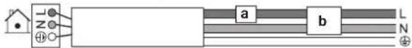
In case of R32 refrigerant, terminal connections T1/T2 are for fire alarm input ONLY. Fire alarm has a higher priority than R32 safety and shuts the entire system down.

a Fire alarm input signal (potential free contact)
2.1 Instructions for equipment using R32 refrigerant

WARNING: MILDLY FLAMMABLE MATERIAL
The refrigerant inside this unit is mildly flammable.

WARNING
- Do NOT pierce or burn refrigerant cycle parts.
- Do NOT use cleaning materials or means to accelerate the defrosting process other than those recommended by the manufacturer.
- Be aware that the refrigerant inside the system is odourless.

WARNING
The appliance shall be stored so as to prevent mechanical damage and in a well-ventilated room without continuously operating ignition sources (example: open flames, an operating gas appliance or an operating electric heater) and have a room size as specified below.

WARNING
Make sure installation, servicing, maintenance and repair comply with instructions from Daikin and with applicable legislation and are executed ONLY by authorised persons.

WARNING
If one or more rooms are connected to the unit using a duct system, make sure:
- there are no operating ignition sources (example: open flames, an operating gas appliance or an operating electric heater) in case the floor area is less than the minimum floor area A (m^2) .
- no auxiliary devices, which may be a potential ignition source, are installed in the duct work (example: hot surfaces with a temperature exceeding 700°C and electric switching device);
- only auxiliary devices approved by the manufacturer are used in the duct work;
- air inlet AND outlet are connected directly to the same room by ducting. Do NOT use spaces such as a false ceiling as a duct for the air inlet or outlet.

WARNING
- Take precautions to avoid excessive vibration or pulsation to refrigeration piping.
- Protect the protection devices, piping and fittings as much as possible against adverse environmental effects.
- Provide space for expansion and contraction of long runs of piping.
- Design and install piping in refrigerating systems such as to minimise the likelihood of hydraulic shock damaging the system.
- Mount the indoor equipment and pipes securely and protect them to avoid accidental rupture of equipment or pipes in case of events such as moving furniture or reconstruction activities.

CAUTION
- Incomplete flaring may cause refrigerant gas leakage.
- Do NOT re-use flares. Use new flares to prevent refrigerant gas leakage.
- Use flare nuts that are included with the unit. Using different flare nuts may cause refrigerant gas leakage.

CAUTION
Do NOT use potential sources of ignition in searching for or detection of refrigerant leaks.

NOTICE
- Do NOT re-use joints and copper gaskets which have been used already.
- Joints made in installation between parts of refrigerant system shall be accessible for maintenance purposes.
2.1.1 Installation space requirements

CAUTION
The total refrigerant charge in the system cannot exceed the requirements for minimum floor area of the smallest room that is served. For minimum floor area requirements for indoor units, see the installation and operation manual of the outdoor unit.

WARNING
This appliance contains R32 refrigerant. For the minimum floor area of the room in which the appliance is stored refer to installation and operation manual of the outdoor unit.

NOTICE
- Protect pipework from physical damage.
- Keep the pipework installation to a minimum.
For the user
3 User safety instructions
Always observe the following safety instructions and regulations.
3.1 General

WARNING
If you are NOT sure how to operate the unit, contact your installer.

WARNING
This appliance can be used by children aged from 8 years and above and persons with reduced physical, sensory or mental capabilities or lack of experience and knowledge if they have been given supervision or instruction concerning use of the appliance in a safe way and understand the hazards involved.
Children SHALL NOT play with the appliance.
Cleaning and user maintenance SHALL NOT be made by children without supervision.

WARNING
To prevent electrical shocks or fire:
- Do NOT rinse the unit.
- Do NOT operate the unit with wet hands.
- Do NOT place any objects containing water on the unit.

CAUTION
- Do NOT place any objects or equipment on top of the unit.
- Do NOT sit, climb or stand on the unit.
- Units are marked with the following symbol:
This means that electrical and electronic products may NOT be mixed with unsorted household waste. Do NOT try to dismantle the system yourself: dismantling the system, treatment of the refrigerant, of oil and of other parts MUST be done by an authorised installer and MUST comply with applicable legislation.
Units MUST be treated at a specialised treatment facility for reuse, recycling and recovery. By ensuring this product is disposed of correctly, you will help to prevent potential negative consequences for the environment and human health. For more information, contact your installer or local authority.
- Batteries are marked with the following symbol:

This means that the batteries may NOT be mixed with unsorted household waste. If a chemical symbol is printed beneath the symbol, this chemical symbol means that the battery contains a heavy metal above a certain concentration.
Possible chemical symbols are: Pb: lead (>0.004%).
Waste batteries MUST be treated at a specialised treatment facility for reuse. By ensuring waste batteries are disposed of correctly, you will help to prevent potential negative consequences for the environment and human health.
3.2 Instructions for safe operation

WARNING
- Do NOT modify, disassemble, remove, reinstall or repair the unit yourself as incorrect dismantling or installation may cause an electrical shock or fire. Contact your dealer.
- In case of accidental refrigerant leaks, make sure there are no naked flames. The refrigerant itself is entirely safe, non-toxic and mildly flammable, but it will generate toxic gas when it accidentally leaks into a room where combustible air from fan heaters, gas cookers, etc. is present. Always have qualified service personnel confirm that the point of leakage has been repaired or corrected before resuming operation.

CAUTION
This unit is equipped with electrically powered safety measures, such as a refrigerant leak detector. In order to be effective, the unit must be electrically powered at all times after installation, except for short service periods.

CAUTION
- NEVER touch the internal parts of the controller.
- Do NOT remove the front panel. Some parts inside are dangerous to touch and appliance problems may happen. For checking and adjusting the internal parts, contact your dealer.

WARNING
This unit contains electrical and hot parts.

WARNING
Before operating the unit, be sure the installation has been carried out correctly by an installer.

CAUTION
It is unhealthy to expose your body to the air flow for a long time.

CAUTION
To avoid oxygen deficiency, ventilate the room sufficiently if equipment with burner is used together with the system.

CAUTION
Do NOT operate the system when using a room fumigation-type insecticide. Chemicals could collect in the unit, and endanger the health of people who are hypersensitive to chemicals.

CAUTION
NEVER expose little children, plants or animals directly to the airflow.

WARNING
Do NOT place a flammable spray bottle near the air conditioner and do NOT use sprays near the unit. Doing so may result in a fire.

WARNING
Keep any required ventilation openings clear of obstructions.
Maintenance and service (see "7 Maintenance and service" [▶ 11])

CAUTION: Pay attention to the fan!
It is dangerous to inspect the unit while the fan is running.
Make sure to turn OFF the main switch before executing any maintenance task.

CAUTION
Do NOT insert fingers, rods or other objects into the air inlet or outlet. When the fan is rotating at high speed, it will cause injury.

WARNING
NEVER replace a fuse with a fuse of a wrong ampere ratings or other wires when a fuse blows out. Use of wire or copper wire may cause the unit to break down or cause a fire.

CAUTION
After a long use, check the unit stand and fitting for damage. If damaged, the unit may fall and result in injury.

CAUTION
Before accessing terminal devices, make sure to interrupt all power supply.

DANGER: RISK OF ELECTROCUTION
To clean the air conditioner or air filter, be sure to stop operation and turn all power supplies OFF. Otherwise, an electrical shock and injury may result.

WARNING
Be careful with ladders when working in high places.

DANGER: RISK OF ELECTROCUTION
Disconnect the power supply for more than 10 minutes, and measure the voltage at the terminals of main circuit capacitors or electrical components before servicing. The voltage MUST be less than 50 V DC before you can touch electrical components. For the location of the terminals, see the warning label for persons performing service and maintenance.

CAUTION
Turn off the unit before cleaning the air filter and air outlet.

WARNING
Do NOT let the indoor unit get wet. Possible consequence: Electrical shock or fire.
About the refrigerant (see "7.3 About the refrigerant" [▶ 12])

WARNING: MILDLY FLAMMABLE MATERIAL
The refrigerant inside this unit is mildly flammable.

WARNING
- Do NOT pierce or burn refrigerant cycle parts.
- Do NOT use cleaning materials or means to accelerate the defrosting process other than those recommended by the manufacturer.
- Be aware that the refrigerant inside the system is odourless.

WARNING
- The refrigerant inside the unit is mildly flammable, but normally does NOT leak. If the refrigerant leaks in the room and comes in contact with fire from a burner, a heater, or a cooker, this may result in fire, or the formation of a harmful gas.
- Turn OFF any combustible heating devices, ventilate the room, and contact the dealer where you purchased the unit.
- Do NOT use the unit until a service person confirms that the part from which the refrigerant leaked has been repaired.

WARNING
The appliance shall be stored in a room without continuously operating ignition sources (example: open flames, an operating gas appliance or an operating electric heater).

WARNING
The R32 refrigerant leakage sensor must be replaced after every detection or at the end of its lifetime. ONLY authorised persons may replace the sensor.
Troubleshooting (see "8 Troubleshooting" [▶ 13])

WARNING
Stop operation and shut OFF the power if anything unusual occurs (burning smells etc.).
Leaving the unit running under such circumstances may cause breakage, electrical shock or fire. Contact your dealer.
4 About the system

WARNING
- Do NOT modify, disassemble, remove, reinstall or repair the unit yourself as incorrect dismantling or installation may cause an electrical shock or fire. Contact your dealer.
- In case of accidental refrigerant leaks, make sure there are no naked flames. The refrigerant itself is entirely safe, non-toxic and mildly flammable, but it will generate toxic gas when it accidentally leaks into a room where combustible air from fan heaters, gas cookers, etc. is present. Always have qualified service personnel confirm that the point of leakage has been repaired or corrected before resuming operation.

WARNING
The unit is equipped with a refrigerant leak detection system for safety.
To be effective, the unit MUST be electrically powered at all times after installation, except for short service periods.

NOTICE
Do NOT use the system for other purposes. In order to avoid any quality deterioration, do NOT use the unit for cooling precision instruments, food, plants, animals, or works of art.

NOTICE
For future modifications or expansions of your system:
A full overview of allowable combinations (for future system extensions) is available in technical engineering data and should be consulted. Contact your installer to receive more information and professional advice.
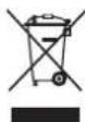
4.1 System layout

INFORMATION
The following figure is an example and may NOT completely match your system layout
a Indoor unit
b Outdoor unit
c User interface
d Suction air
e Discharge air
f Refrigerant piping + interconnection cable
g Drain pipe
5 User interface

CAUTION
- NEVER touch the internal parts of the controller.
- Do NOT remove the front panel. Some parts inside are dangerous to touch and appliance problems may happen. For checking and adjusting the internal parts, contact your dealer.

NOTICE
Do NOT wipe the controller operation panel with benzine, thinner, chemical dust cloth, etc. The panel may get discoloured or the coating peeled off. If it is heavily dirty, soak a cloth in water-diluted neutral detergent, squeeze it well and wipe the panel clean. Wipe it with another dry cloth.

NOTICE
NEVER press the button of the user interface with a hard, pointed object. The user interface may be damaged.

NOTICE
NEVER pull or twist the electric wire of the user interface. It may cause the unit to malfunction.
This operation manual offers a non-exhaustive overview of the main functions of the system.
For more information about the user interface, see the operation manual of the installed user interface.
6 Operation
6.1 Operation range

INFORMATION
For the operation limits see the technical data of the connected outdoor unit.
6.2 About operation modes

INFORMATION
Depending on the installed system, some operation modes will not be available.
- The air flow rate may adjust itself depending on the room temperature or the fan may stop immediately. This is not a malfunction.
- If the main power supply is turned off during operation, operation will restart automatically after the power turns back on again.
- Setpoint. Target temperature for the Cooling, Heating, and Auto operation modes.
- Setback. A function that keeps the room temperature in a specific range when the system is turned off (by the user, the schedule function, or the OFF timer).
6.2.1 Basic operation modes
The indoor unit can operate in various operation modes.
| Icon Operation mode | |
| Cooling. In this mode, cooling will be activated as required by the setpoint, or by Setback operation. | |
| Heating. In this mode, heating will be activated as required by the setpoint, or by Setback operation. | |
| Fan only. In this mode, air circulates without heating or cooling. | |
| Auto. In Auto mode, the indoor unit automatically switches between heating and cooling mode, as required by the setpoint. | |
6.2.2 Special heating operation modes
| Operation Description | |
Defrost To prevent a loss of heating capacity due to frost accumulation in the outdoor unit, the system will automatically switch to defrost operation.During defrost operation, the indoor unit fan will stop operation, and the following icon will appear on the home screen: The system will resume normal operation after approximately 6 to 8 minutes. The system will resume normal operation after approximately 6 to 8 minutes. | |
| Hot start During hot start, the indoor unit fan will stop operation, and the following icon will appear on the home screen: |
6.3 To operate the system

INFORMATION
For setting of the operation mode or other settings, see the reference guide or operation manual of the user interface.
7 Maintenance and service
7.1 Precautions for maintenance and service

NOTICE
Maintenance MUST be done by an authorised installer or service agent.
We recommend performing maintenance at least once a year. However, applicable legislation might require shorter maintenance intervals.

CAUTION: Pay attention to the fan!
It is dangerous to inspect the unit while the fan is running.
Make sure to turn OFF the main switch before executing any maintenance task.

CAUTION
Do NOT insert fingers, rods or other objects into the air inlet or outlet. When the fan is rotating at high speed, it will cause injury.

NOTICE
NEVER inspect or service the unit by yourself. Ask a qualified service person to perform this work. However, as end user, you may clean the air filter and air outlet.

WARNING
NEVER replace a fuse with a fuse of a wrong ampere ratings or other wires when a fuse blows out. Use of wire or copper wire may cause the unit to break down or cause a fire.

CAUTION
Do NOT insert fingers, rods or other objects into the air inlet or outlet. Do NOT remove the fan guard. When the fan is rotating at high speed, it will cause injury.

CAUTION
After a long use, check the unit stand and fitting for damage. If damaged, the unit may fall and result in injury.

NOTICE
Do NOT wipe the controller operation panel with benzine, thinner, chemical dust cloth, etc. The panel may get discoloured or the coating peeled off. If it is heavily dirty, soak a cloth in water-diluted neutral detergent, squeeze it well and wipe the panel clean. Wipe it with another dry cloth.

CAUTION
Before accessing terminal devices, make sure to interrupt all power supply.

DANGER: RISK OF ELECTROCUTION
To clean the air conditioner or air filter, be sure to stop operation and turn all power supplies OFF. Otherwise, an electrical shock and injury may result.

WARNING
Be careful with ladders when working in high places.
Following symbols may occur on the indoor unit:
Symbol Explanation
Measure the voltage at the terminals of main circuit capacitors or electrical components before servicing.

DANGER: RISK OF ELECTROCUTION
Disconnect the power supply for more than 10 minutes, and measure the voltage at the terminals of main circuit capacitors or electrical components before servicing. The voltage MUST be less than 50 V DC before you can touch electrical components. For the location of the terminals, see the warning label for persons performing service and maintenance.
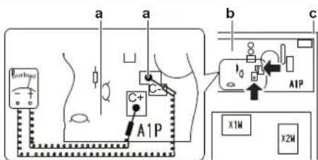
a Residual voltage measuring points (C-, C+)
b Printed circuit board
c Control box
7.2 Cleaning the air filter and air outlet

CAUTION
Turn off the unit before cleaning the air filter and air outlet.

NOTICE
- Do NOT use gasoline, benzene, thinner polishing powder or liquid insecticide. Possible consequence: Discoloration and deformation.
- Do NOT use water or air of 50°C or higher. Possible consequence: Discoloration and deformation.
7.2.1 To clean the air filter
When to clean the air filter:
- Rule of thumb: Clean every 6 months. If the air in the room is extremely contaminated, increase the cleaning frequency.
- Depending on the settings, the user interface can display the "Time to clean filter" notification. Clean the air filter when the notification displays.
- If the dirt becomes impossible to clean, change the air filter (= optional equipment).
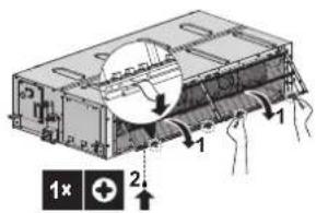
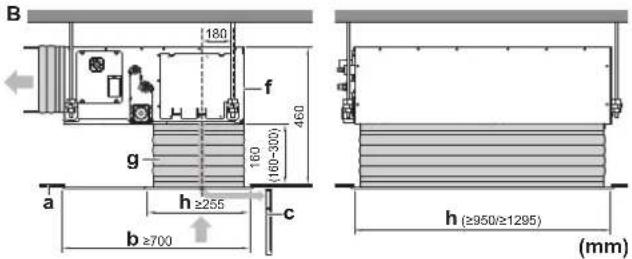
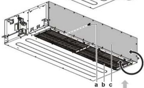
How to clean the air filter:
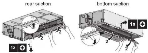
1 Remove the filter fixing screw. In case of installation without duct on the suction side, remove the filter fixing screw.
2 Remove the air filter. Pull its cloth upward (in case of rear suction) or backward (in case of bottom suction).
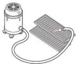
3 Clean the air filter. Use a vacuum cleaner or wash with water. If the air filter is very dirty, use a soft brush and neutral detergent.
natural_image
Line drawing of a vacuum cleaner connected to a grid-based sensor or circuit board (no text or symbols present)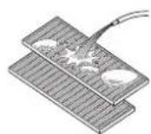
4 Dry the air filter in the shadow.
5 Re-attach the air filter. Align the 4 hanger brackets and push the 4 clips in their place and pull the cloth if necessary.
6 Confirm that all hangers are fixed.
7 Re-install the filter fixing screw. In case of installation without duct on the suction side, re-install the filter fixing screw.
rear suction
bottom suction
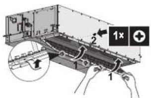
8 In case of bottom suction with duct, close the protective guard. In case of rear suction with duct, close service duct opening.
9 Turn ON the power.
10 To remove warning screens, see the reference guide of the user interface.
7.2.2 To clean the air outlet

WARNING
Do NOT let the indoor unit get wet. Possible consequence: Electrical shock or fire.
Clean with a soft cloth. If it is difficult to remove stains, use water or a neutral detergent.
7.3 About the refrigerant
This product contains fluorinated greenhouse gases. Do NOT vent gases into the atmosphere.
Refrigerant type: R32
Global warming potential (GWP) value: 675
Periodical inspections for refrigerant leaks may be required depending on the applicable legislation. Contact your installer for more information.

NOTICE
Applicable legislation on fluorinated greenhouse gases requires that the refrigerant charge of the unit is indicated both in weight and CO_2 equivalent.
Formula to calculate the quantity in CO_2 equivalent tonnes: GWP value of the refrigerant × total refrigerant charge [in kg]/1000
Contact your installer for more information.

WARNING: MILDLY FLAMMABLE MATERIAL
The refrigerant inside this unit is mildly flammable.

WARNING
- The refrigerant inside the unit is mildly flammable, but normally does NOT leak. If the refrigerant leaks in the room and comes in contact with fire from a burner, a heater, or a cooker, this may result in fire, or the formation of a harmful gas.
- Turn OFF any combustible heating devices, ventilate the room, and contact the dealer where you purchased the unit.
- Do NOT use the unit until a service person confirms that the part from which the refrigerant leaked has been repaired.

WARNING
The appliance shall be stored in a room without continuously operating ignition sources (example: open flames, an operating gas appliance or an operating electric heater).

WARNING
- Do NOT pierce or burn refrigerant cycle parts.
- Do NOT use cleaning materials or means to accelerate the defrosting process other than those recommended by the manufacturer.
- Be aware that the refrigerant inside the system is odourless.
7.3.1 About the refrigerant leakage sensor

WARNING
The R32 refrigerant leakage sensor must be replaced after every detection or at the end of its lifetime. ONLY authorised persons may replace the sensor.

NOTICE
The R32 refrigerant leakage sensor is a semiconductor detector which may incorrectly detect substances other than R32 refrigerant. Avoid using chemical substances (e.g. organic solvents, hair spray, paint) in high concentrations, in the close proximity of the indoor unit because this may cause misdetection by the R32 refrigerant leakage sensor.

NOTICE
Functionality of the safety measures are periodically automatically checked. In case of malfunction, an error code will be displayed on the user interface.

INFORMATION
The sensor has a lifetime of 10 years. The user interface displays error "CH-05" 6 months before the end of the sensor lifetime and error "CH-02" after the end of the sensor lifetime. For more information, refer to the reference guide of the user interface and contact your dealer.
In case of detection when the unit is operating
1 The user interface displays error "A0-11" and emits an alarm sound. The status indicator blinks.
2 Contact your dealer immediately. For more information, see the installation manual of the outdoor unit.
In case of detection when the unit is in standby
When the detection occurs when the unit is in standby, the unit performs a "false detection check".
False detection check
1 The fan starts turning on the lowest setting.
2 The user interface displays error "A0-13" and emits an alarm sound. The status indicator blinks.
3 The sensor checks if a refrigerant leakage or misdetection occurred.
- No refrigerant leakage detected. Result: The system resumes normal operation after approximately 2 minutes.
- Refrigerant leakage detected. Result:
1 The user interface displays error "A0-11" and emits an alarm sound. The status indicator blinks.
2 Contact your dealer immediately. For more information, see the installation manual of the outdoor unit.

INFORMATION
The minimum airflow during normal operation or during the refrigerant leakage detection is always >240 m^3/h .

INFORMATION
To stop the alarm of the user interface, see the reference guide of the user interface.
8 Troubleshooting
If one of the following malfunctions occur, take the measures shown below and contact your dealer.

WARNING
Stop operation and shut OFF the power if anything unusual occurs (burning smells etc.).
Leaving the unit running under such circumstances may cause breakage, electrical shock or fire. Contact your dealer.
The system MUST be repaired by a qualified service person.
| Malfunction | Measure |
| If a safety device such as a fuse, a circuit breaker or a residual current device frequently actuates or the ON/OFF switch does NOT function properly. | Turn OFF all main power supply switches to the unit. |
| If water leaks from the unit. | Stop operation. |
| The operation switch does NOT function properly. | Turn OFF the power supply. |
| If the user interface displays [IMAGE] | Notify your installer and report the error code. To display an error code see the reference guide of the user interface. |
If the system does NOT operate properly except for the above mentioned cases and none of the above mentioned malfunctions is evident, investigate the system in accordance with the following procedures.

INFORMATION
Refer to the reference guide located on https://www.daikin.eu for more troubleshooting tips. Use the search function 🔒 to find your model.
If after checking all above items, it is impossible to fix the problem yourself, contact your installer and state the symptoms, the complete model name of the unit (with manufacturing number if possible) and the installation date (possibly listed on the warranty card).
9 Relocation
Contact your dealer to remove and reinstall the entire unit. Moving units requires technical expertise.
10 Disposal

NOTICE
Do NOT try to dismantle the system yourself: dismantling of the system, treatment of the refrigerant, oil and other parts MUST comply with applicable legislation. Units MUST be treated at a specialised treatment facility for reuse, recycling and recovery.
For the installer
11 About the box
11.1 Indoor unit
11.1.1 To remove the accessories from the indoor unit
1 Remove the air filter.
2 Remove the accessories from the inside of the unit.
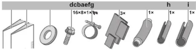
a Installation and operation manual
b General safety precautions
c Washers for hanger brackets
d Screws for duct flanges
e Metal clamp
f Sealing pads: Large (drain pipe), medium 1 (gas pipe), medium 2 (liquid pipe)
g Drain hose
h Insulation piece: Small (liquid pipe)
i Insulation piece: Large (gas pipe)
12 Unit installation
12.1 Preparing the installation site
Avoid installation in an environment with a lot of organic solvents such as ink and siloxane.

WARNING
The appliance shall be stored in a room without continuously operating ignition sources (example: open flames, an operating gas appliance or an operating electric heater).
12.1.1 Installation site requirements of the indoor unit
Minimum floor area requirements

CAUTION
The total refrigerant charge in the system cannot exceed the requirements for minimum floor area of the smallest room that is served. For minimum floor area requirements for indoor units, see the installation and operation manual of the outdoor unit.

INFORMATION
The sound pressure level is less than 70 dBA.

INFORMATION
Equipment meets the requirement for commercial and light-industrial location when professionally installed and maintained.

NOTICE
If the equipment is installed closer than 30 m to a residential location, the professional installer MUST evaluate the EMC situation before installation.

CAUTION
This equipment is NOT intended for use in residential locations and will NOT guarantee to provide adequate protection to radio reception in such locations.

CAUTION
Appliance NOT accessible to the general public, install it in a secured area, protected from easy access.
This unit, both indoor and outdoor, is suitable for installation in a commercial and light industrial environment.

WARNING
Keep any required ventilation openings clear of obstructions.
- Drainage. Make sure condensation water can be evacuated properly.
- Ceiling insulation. When conditions in the ceiling exceed 30°C and a relative humidity of 80%, or when fresh air is inducted into the ceiling, then additional insulation is required (minimum 10 mm thickness, polyethylene foam).
- Protective guards. Make sure to install protective guards (field supply) on the suction and discharge side to prevent somebody from touching the fan blades or heat exchanger.
- Spacing. Mind the following requirements:
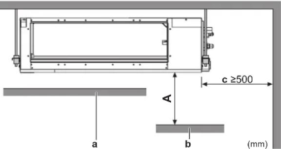
A Minimum distance to the floor
2.5 m to avoid accidental touching
a Ceiling
b Floor surface
c Maintenance space
- Discharge grille. Minimum requirement installation height of discharge grille ≥ 1.8 m.
Service space and ceiling opening size
Make sure ceiling opening is big enough to ensure a sufficient clearance for maintenance and service.
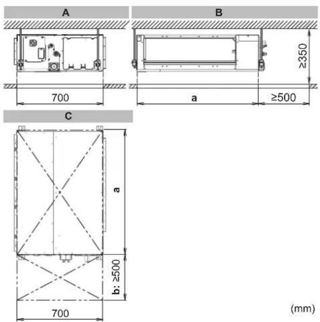
A Side view: refrigerant piping, drain piping, control box
B Side view: air inlet
C Top view
a Ceiling opening
Class 50\~80: 1000 mm
Class 100+125: 1400 mm
b Service space
Installation options
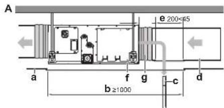
A Installation with rear canvas duct and duct service opening
B Installation with bottom canvas duct and air inlet grill
a Ceiling surface
b Ceiling opening
c Air filter
d Air inlet duct
e Duct service opening
f Interchangeable plate
g Canvas connection for air inlet side (field supply)
h Minimum opening for protective guard (field supply)
Class 50-80: 950×255 mm
Class 100+125: 1295×255 mm
- Air filter fixing. In case of installation without duct on the air inlet side, fix the air filter on the service cover side by screw (field supply).

Some options may require additional service space. Sees the installation manual of the used option before installation.
12.2 Mounting the indoor unit
12.2.1 Guidelines when installing the indoor unit Installation options

CAUTION
In case of installation WITHOUT duct on the air inlet side, fix the air filter on the service cover side by screw (field supply).

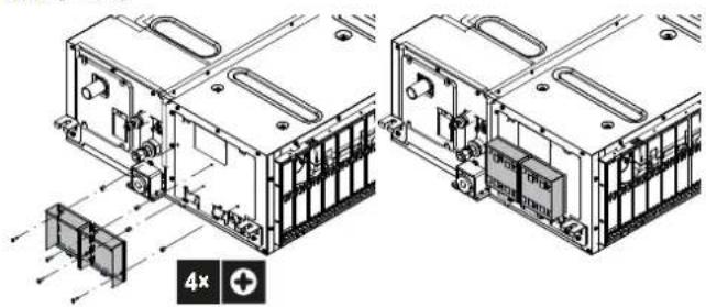
INFORMATION
The unit can be used with bottom suction by replacing the interchangeable plate by the air filter holding plate.
a Thread cutting screw M4×20 (field supply) in case of installation without duct on air inlet side
b Air filter holding plate with air filters
c Interchangeable plate
- Ceiling strength. Check whether the ceiling is strong enough to support the weight of the unit. If there is a risk, reinforce the ceiling before installing the unit.
- For existing ceilings, use anchors.
- For new ceilings, use sunken inserts, sunken anchors or other field supplied parts.
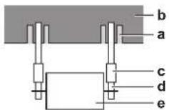
a Anchor
b Ceiling slab
c Long nut or turnbuckle
d Suspension bolt
e Indoor unit
- Suspension bolts. Use M10 suspension bolts for installation. Attach the hanger bracket to the suspension bolt. Fix it securely using a nut and washer from the upper and lower sides of the hanger bracket.
12 Unit installation
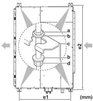
a Nut (field supply)
b Washer (accessories)
c Hanger bracket
d Double nut (field supply)
e1 Suspension bolt pitch
Class 50\~125: 630 mm
e2 Suspension bolt pitch
Class 50\~80: 1038 mm
Class 100\~125: 1438 mm
- Level. Make sure the unit is level at all four corners using a level or a water-filled vinyl tube.
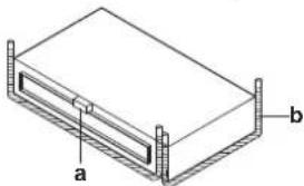
natural_image
Isometric diagram of a rectangular electronic component with labeled parts a and b (no text or symbols beyond labels)a Water level
b Vinyl tube

NOTICE
Do NOT install the unit tilted. Possible consequence: If the unit is tilted against the direction of the condensate flow (the drain piping side is raised), the float switch might malfunction and cause water to drip.

INFORMATION
Optional equipment. When installing optional equipment, also read the installation manual of the optional equipment. Depending on the field conditions, it might be easier to install the optional equipment first.
Installation box for the optional output PCB
An additional Installation box for the optional output PCB is required; see the option list of the indoor unit. For installation of the installation box, refer to the manual of the installation box. The wiring between the main PCB and the optional output PCB must be led together with the transmission cable; never use the same route as for the power supply cable. See "14.2 To connect the electrical wiring to the indoor unit" [▶ 20].
natural_image
Technical line drawing of two mechanical or electronic components with internal components and mounting features (no text or symbols)12.2.2 Guidelines when installing the ducting

WARNING
Do NOT install operating ignition sources (example: open flames, an operating gas appliance or an operating electric heater) in the duct work.

CAUTION
- Make sure the installation of the duct does NOT exceed the setting range of the external static pressure for the unit. Refer to the technical datasheet of your model for the setting range.
- Make sure to install the canvas duct so vibrations are NOT transmitted to the duct or ceiling. Use a sound-absorbing material (insulation material) for the lining of the duct and apply vibration insulation rubber to the hanging bolts.
- When welding, make sure NOT to spatter onto the drain pan or the air filter.
- If the metal duct passes through a metal lath, wire lath or metal plate of the wooden structure, separate the duct and wall electrically.
- Install the outlet grille in a position where the airflow will not come into direct contact with people.
- Do NOT use booster fans in the duct. Use the function to adjust the fan rate setting automatically (see "16 Configuration" [▶ 21]).
The ducting is to be field supplied.
1 Connect the canvas duct to the inside of the flange on both inlet and outlet side. For connecting the canvas duct, use field supply screws.
2 Connect the duct to the canvas duct.
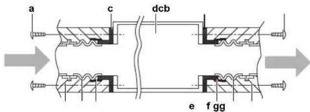
a Screws for inlet duct flanges (field supply)
b Screws for outlet duct flanges (accessory)
c Flange (located on the unit)
d Indoor unit
e Insulation (field supply)
f Canvas duct (field supply)
g Aluminium tape (field supply)
- Fixing screws. When installing an air inlet duct, select fixing screws that stick out 5 mm on the inside of the flange to protect the air filter from damage during maintenance of the filter.
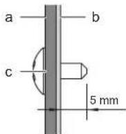
a Air inlet duct
b Inside of the flange
c Fixing screw
3 Wind aluminium tape around the flange and duct connection. Make sure there are no air leaks at any other connection.
4 Insulate the duct to prevent condensation from forming. Use glass wool or polyethylene foam 25 mm thick.
- Filter. Be sure to attach an air filter inside the air passage on the intake side. Use an air filter with dust collecting efficiency ≥ 50% (gravimetric method).
12.2.3 Guidelines when installing the drain piping
Make sure condensation water can be evacuated properly. This involves:
- General guidelines
- Connecting the drain piping to the indoor unit
- Checking for water leaks
General guidelines
- Pipe length. Keep drain piping as short as possible.
- Pipe size. Keep the pipe size equal to or greater than that of the connecting pipe (vinyl pipe of 25 mm nominal diameter and 32 mm outer diameter).
- Slope. Make sure the drain piping slopes down (at least 1/100) to prevent air from being trapped in the piping. Use hanging bars as shown.
a Hanging bar Allowed Not allowed
- Condensation. Take measures against condensation. Insulate the complete drain piping in the building.
-
Rising piping. If necessary to make the slope possible, you can install rising piping.
-
Drain hose inclination: 0\~75 mm to avoid stress on the piping and to avoid air bubbles.
- Rising piping: ≤300 mm from the unit, ≤625 mm perpendicular to the unit.
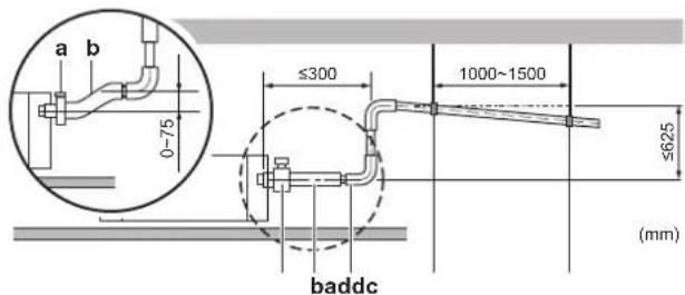
a Metal clamp (accessory)
b Drain hose (accessory)
c Rising drain piping (vinyl pipe of 25 mm nominal diameter and 32 mm outer diameter) (field supply)
d Hanging bars (field supply)
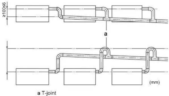
- Combining drain pipes. You can combine drain pipes. Make sure to use drain pipes and T-joints with the correct gauge for the operating capacity of the units.
To connect the drain piping to the indoor unit
NOTICE
Incorrect connection of the drain hose might cause leaks, and damage the installation space and surroundings.
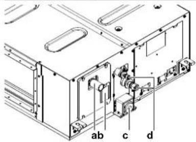
a Drain pipe connection
b Water inlet cover
c Drain outlet for maintenance
d Refrigerant pipes
Drain piping connection
1 Push the drain hose as far as possible over the drain pipe connection.
2 Tighten the metal clamp until the screw head is less than 4 mm from the metal clamp part.
3 Check for water leaks (see "To check for water leaks" [▶ 18]).
4 Wind the large sealing pad (= insulation) around the metal clamp and drain hose, and fix it with tie wraps.
5 Connect the drain piping to the drain hose.
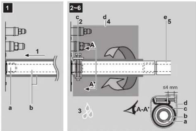
a Drain pipe connection (attached to the unit)
b Drain hose (accessory)
c Metal clamp (accessory)
d Large sealing pad (accessory)
e Drain piping (field supply)
13 Piping installation

NOTICE
- Do NOT remove the drain pipe plug. Water might leak out.
- Use the drain outlet only to discharge the water if the drain pump is not used or before maintenance.
- Insert and remove the drain plug gently. Excessive force may deform the drain socket of the drain pan.
Drain outlet for maintenance
Pull out the plug.
- Do NOT wiggle the plug up and down.
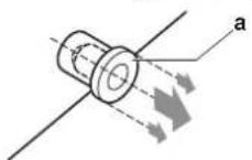
Push in the plug.
- Set the plug and push it in using a Phillips screwdriver.
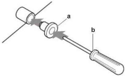
a Drain plug
b Philips screwdriver
To check for water leaks
The procedure differs depending on whether installation of the system is already completed. When installation of the system is not yet completed, temporarily connect the user interface and power supply to the unit.
When installation of the system is not yet completed
1 Temporarily connect electrical wiring.
- Remove the service cover.
- Connect the power supply.
- Connect the user interface.
- Reattach the service cover.
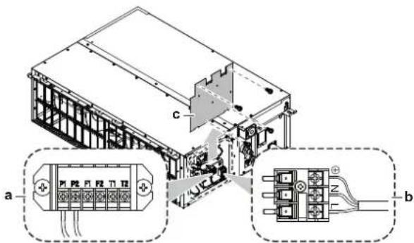
a User interface terminal block
b Power supply terminal block
c Service cover with wiring diagram
2 Turn ON the power supply.
3 Start fan only operation (see the reference guide or the service manual of the user interface).
4 Remove the water inlet cover (1 screw).
5 Gradually pour approximately 1 l of water through the water inlet, and check for leaks.
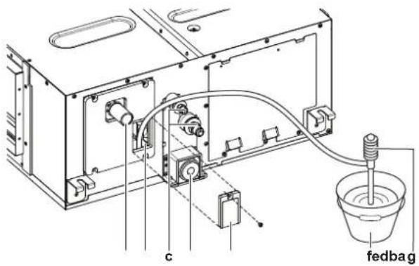
a Drain connection
b Water inlet
c Refrigerant pipes
d Drain outlet for maintenance
e Water inlet cover
f Bucket (adding water through water inlet)
g Portable pump
6 Turn OFF the power.
7 Disconnect the electrical wiring.
- Remove the service cover.
- Disconnect the power supply.
- Disconnect the user interface.
- Reattach the service cover.
When installation of the system is already completed
1 Start cooling operation (see the reference guide or the service manual of the user interface).
2 Gradually pour approximately 1 l of water through the water inlet, and check for leaks (see "When installation of the system is not yet completed" [▶ 18]).
13 Piping installation
13.1 Preparing refrigerant piping
13.1.1 Refrigerant piping requirements

CAUTION
Piping MUST be installed according to instructions given in "13 Piping installation" [▶ 18]. Only mechanical joints (e.g. braze+flare connections) that are compliant with the latest version of ISO14903 can be used.

NOTICE
The piping and other pressure-containing parts shall be suitable for refrigerant. Use phosphoric acid deoxidised seamless copper for refrigerant piping.
- Foreign materials inside pipes (including oils for fabrication) must be ≤30 mg/10 m.
Refrigerant piping diameter
For piping connections of the indoor unit, use the following piping diameters:
| Class | Pipe outer diameter (mm) | |
| Liquid pipe | Gas pipe | |
| 50~80 | ∅6.4 | ∅12.7 |
| 100+125 | ∅9.5 | ∅15.9 |
Refrigerant piping material
- Piping material: phosphoric acid deoxidised seamless copper
- Flare connections: Only use annealed material.
- Piping temper grade and thickness:
| Outer diameter (∅) | Temper grade Thickness (t) (a) | ||
| 6.4 mm (1/4") Annealed (O) ≥0.8 mm | [ASGW] | ||
| 9.5 mm (3/8") | |||
| 12.7 mm (1/2") | |||
| 15.9 mm (5/8") | |||
(a) Depending on the applicable legislation and the maximum working pressure of the unit (see "PS High" on the unit name plate), larger piping thickness might be required.
13.1.2 Refrigerant piping insulation
- Use polyethylene foam as insulation material:
- with a heat transfer rate between 0.041 and 0.052 W/mK (0.035 and 0.045 kcal/mh°C)
- with a heat resistance of at least 120°C
- Insulation thickness
| Pipe outer diameter ( _p ) | Insulation inner diameter ( _i ) | Insulation thickness (t) |
| 6.4 mm (1/4") 8~10 mm | ≥ 10 mm | |
| 9.5 mm (3/8") 10~14 mm | ≥ 13 mm | |
| 12.7 mm (1/2") 14~16 mm | ≥ 13 mm | |
| 15.9 mm (5/8") 16~20 mm | ≥ 13 mm |
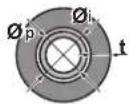
If the temperature is higher than 30^ C and the humidity is higher than RH 80%, the thickness of the insulation materials should be at least 20 mm to prevent condensation on the surface of the insulation.
13.2 Connecting the refrigerant piping

DANGER: RISK OF BURNING/SCALDING
13.2.1 To connect the refrigerant piping to the indoor unit

CAUTION
Install the refrigerant piping or components in a position where they are unlikely to be exposed to any substance which may corrode components containing refrigerant, unless the components are constructed of materials that are inherently resistant to corrosion or are suitably protected against corrosion.

WARNING: MILDLY FLAMMABLE MATERIAL
The refrigerant inside this unit is mildly flammable.
- Pipe length. Keep refrigerant piping as short as possible.
- Flare connections. Connect refrigerant piping to the unit using flare connections.
- Insulation. Insulate the refrigerant piping on the indoor unit as follows:
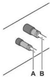
natural_image
Two cylindrical electronic components with labeled points A and B, connected by wires (no text or symbols beyond labels)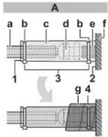
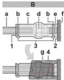
A Liquid piping B Gas piping
a Insulation material (field supply)
b Tie wrap (field supply)
c Insulation pieces: Large (gas pipe), small (liquid pipe) (accessories)
d Flare nut (attached to the unit)
e Refrigerant pipe connection (attached to the unit)
f Unit
g Sealing pads: Medium 1 (gas pipe), medium 2 (liquid pipe) (accessories)
1 Turn up the seams of the insulation pieces.
2 Attach to the base of the unit.
3 Tighten the tie wrap on the insulation pieces.
4 Wrap the sealing pad from the base of the unit to the top of the flare nut.

NOTICE
Make sure to insulate all refrigerant piping. Any exposed piping might cause condensation.
14 Electrical installation

DANGER: RISK OF ELECTROCUTION

WARNING
ALWAYS use multicore cable for power supply cables.

WARNING
Use an all-pole disconnection type breaker with at least 3 mm between the contact point gaps that provides full disconnection under overvoltage category III.

WARNING
If the supply cord is damaged, it MUST be replaced by the manufacturer, its service agent or similarly qualified persons in order to avoid a hazard.
14.1 Specifications of standard wiring components

NOTICE
We recommend using solid (single-core) wires. If stranded wires are used, slightly twist the strands to consolidate the end of the conductor for either direct use in the terminal clamp or insertion in a round crimp-style terminal. Details are described in "Guidelines when connecting the electrical wiring" in the installer reference guide.
| Power supply | |
| Voltage | 220~240 V/220 V |
| Frequency | 50/60 Hz |
| Phase | 1~ |
14 Electrical installation
| Power supply | |
| MCA(a) | FXMA50: 1.8 A |
| FXMA63: 2 A | |
| FXMA80: 2.4 A | |
| FXMA100: 3 A | |
| FXMA125: 3.2 A | |
^(a) MCA=Minimum circuit ampacity. Stated values are maximum values (see electrical data of indoor unit for exact values).
| Components | |
| Power supply cable MUST | comply with national wiring regulation.3-core cableWire size based on the current, but not less than 1.5 mm2 |
| Interconnection wiring (indoor ↔ outdoor) | Only use harmonised wire providing double insulation and suitable for applicable voltage2-core cableMinimum size 0.75 mm2 |
| User interface cable Only | use harmonised wire providing double insulation and suitable for applicable voltage2-core cableMinimum size 0.75 mm2Maximum length 500 m |
| Recommended circuit breaker | 6 A |
| Residual current device MUST | comply with national wiring regulation |
14.2 To connect the electrical wiring to the indoor unit

NOTICE
- Follow the wiring diagram (delivered with the unit, located at the inside of the service cover).
- For instructions on how to connect the optional equipment, see the installation manual delivered with the optional equipment.
- Make sure the electrical wiring does NOT obstruct proper reattachment of the service cover.
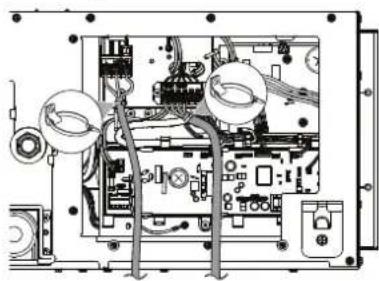
It is important to keep the power supply and the transmission wiring separated from each other. In order to avoid any electrical interference the distance between both wirings should ALWAYS be at least 50 mm.

NOTICE
Be sure to keep the power line and transmission line apart from each other. Transmission wiring and power supply wiring may cross, but may NOT run parallel.
1 Remove the service cover.
2 User interface cable: Route the cable through the frame, connect the cable to the terminal block (symbols P1, P2).
3 Interconnection cable: Route the cable through the frame, connect the cable to the terminal block (make sure the symbols F1, F2 match with the symbols on the outdoor unit). Bundle the interconnection cable with the user interface cable and fix them with a tie wrap on the wiring fixture.
4 Power supply cable: Route the cable through the frame and connect the cable to the terminal block (L, N, earth). Fix the cable with a tie wrap on the wiring fixture.
a Circuit breaker
b Residual current device
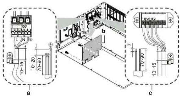
a Power supply cable
b Service cover with wiring diagram
c User interface cable and interconnection cable
5 Plastic clamp for tie wrap: Pass tie wraps through the plastic clamps and fasten to fix the cables.
natural_image
Interior view of an electronic device showing internal components and wiring (no text or symbols visible)6 Reattach the service cover.
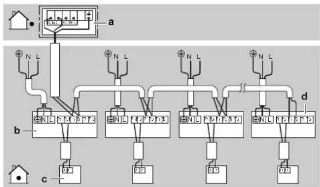
Complete system example
1 user interface controls 1 indoor unit.
flowchart
graph TD
    A["House"] --> B["Control Panel"]
    B --> C["Terminal a"]
    B --> D["Terminal b"]
    B --> E["Terminal c"]
    B --> F["Terminal d"]
    style A fill:#f9f,stroke:#333
    style B fill:#ccf,stroke:#333
    style C fill:#dfd,stroke:#333
    style D fill:#dfd,stroke:#333
    style E fill:#dfd,stroke:#333
    style F fill:#dfd,stroke:#333
a Outdoor unit
b Indoor unit
c User interface
d Most downstream indoor unit

NOTICE
For the use of group control and related limitations refer to manual of outdoor unit.

CAUTION
- Each indoor unit has to be connected to a separate user interface. Only a safety system compatible remote controller can be used as the user interface. See technical data sheet for remote controller compatibility (e.g. BRC1H52/82*).
- The user interface has to be put in the same room as the indoor unit. For details, please refer to the installation and operation manual of the user interface.

CAUTION
In case shielded wire is used, connect the shielding to the outdoor unit side only.
15 Commissioning

NOTICE
General commissioning checklist. Next to the commissioning instructions in this chapter, a general commissioning checklist is also available on the Daikin Business Portal (authentication required).
The general commissioning checklist is complementary to the instructions in this chapter and can be used as a guideline and reporting template during commissioning and hand-over to the user.

NOTICE
ALWAYS operate the unit with thermistors and/or pressure sensors/switches. If NOT, burning of the compressor might be the result.
15.1 Checklist before commissioning
1 After the installation of the unit, check the items listed below.
2 Close the unit.
3 Power up the unit.
| You have read the complete installation and operation instructions described in the installer and user reference guide. | |
| The indoor unit is properly mounted. | |
| The outdoor unit is properly mounted. | |
| The drain piping is properly installed and insulated, and drainage flows smoothly. Check for water leaks.Possible consequence: condensate water might drip. | |
| The ducting is properly installed and insulated. | |
| The refrigerant pipes (gas and liquid) are installed correctly and thermally insulated. | |
| There are NO refrigerant leaks. | |
| There are NO missing phases or reversed phases. | |
| The system is properly earthed and the earth terminals are tightened. |
| The fuses or locally installed protection devices are installed according to this document, and have NOT been bypassed. | |
| The power supply voltage matches the voltage on the identification label of the unit. | |
| There are NO loose connections or damaged electrical components in the switch box. | |
| There are NO damaged components or squeezed pipes on the inside of the indoor and outdoor units. | |
| The stop valves (gas and liquid) on the outdoor unit are fully open. |
15.2 To perform a test run

INFORMATION
- Perform the test run according to the instructions in the outdoor unit manual.
- The test run is only completed if there is no malfunction code displayed on the user interface or the outdoor unit 7-segment display.
- See the service manual for the complete list of error codes and a detailed troubleshooting guideline for each error.

NOTICE
Do NOT interrupt the test run.
16 Configuration
16.1 Field setting
Make the following field settings so that they correspond with the actual installation setup and with the needs of the user:
- Bottom suction or rear suction installation
- External static pressure setting using:
- Airflow automatic adjustment setting
- User interface
- Air volume when thermostat control is OFF
- Time to clean air filter
- Thermostat sensor selection
- Thermostat differential changeover (if remote sensor is used)
- Differential for automatic changeover
- Auto-restart after power failure
- T1/T2 input setting
Setting: Bottom suction or rear suction installation
This setting must correspond with the installation type: rear suction (default) or bottom suction.
| If you have the installation with... | Then^(1) | ||
| M SW | — | ||
| Rear suction | 13(23) | 11 | 01 |
| Bottom suction | 02 | ||
Setting: External static pressure

INFORMATION
- The fan speed of the indoor unit is preset to ensure the standard external static pressure.
- To set a higher or lower external static pressure, reset the initial setting with the user interface.
Settings for external static pressure can be achieved in 2 ways:
- Using the airflow automatic adjustment function
- Using the user interface
To set external static pressure by airflow automatic adjustment function

NOTICE
- Do NOT adjust the dampers during the fan only operation for airflow automatic adjustment.
- For the external static pressure higher than 100 Pa, do NOT use airflow automatic adjustment function.
-
If the ventilation paths have been changed, perform the airflow automatic adjustment again.
-
Test run MUST be done with a dry coil, run the unit for 2 hours with fan only to dry the coil.
- Check if the power supply wiring, duct, air filter are properly attached. If the closing damper is installed in the unit, make sure it is open.
- If there is more than one air inlet and outlet, adjust the dampers so that the airflow rate of each air inlet and outlet is conform with the designed airflow rate.
1 Operate the unit in fan only mode prior to using the airflow automatic adjustment function.
2 Stop the air conditioning unit.
3 Set the value number “—” to 03 for M 11(21) and SW 7.
4 Start the air conditioning unit.
Result: The operation lamp lights up and the unit starts the fan operation for airflow automatic adjustment.
5 After airflow automatic adjustment is finished (air conditioning unit will stop) check if the value number “—” is set to 02. If there is no change, perform the setting again.
| Setting content: Then | (1) | ||
| M SW — | |||
| Airflow adjustment is OFF 11(21) 7 01 | |||
| Completion of automatic airflow adjustment 02 | |||
| Start of automatic airflow adjustment | 03 | ||
To set external static pressure by the user interface
Check the indoor unit setting: the value number “—” must be set to 01 for M 11(21) and SW 7.
1 Change the value number “—” according to the external static pressure of the duct to be connected as in table below.
| M | SW | — | External static pressure (Pa)(1) |
| 13(23) | 6 | 01 | — |
| 02 | 50 | ||
| 03 | 60 | ||
| 04 | 70 | ||
| 05 | 80 | ||
| 06 | 90 | ||
| 07 | 100 | ||
| 08 | 110 | ||
| 09 | 120 | ||
| 10 | 130 | ||
| 11 | 140 | ||
| 12 | 150 | ||
| 13 | 160 | ||
| 14 | 180 | ||
| 15 | 200 |
Setting: Air volume when thermostat control is OFF
This setting must correspond with the needs of the user. It determines the fan speed of the indoor unit during thermostat OFF condition.
1 If you have set the fan to operate, set the air volume speed:
| If you want... | Then(1) | |||
| M | SW | — | ||
| During thermostat OFF at cooling operation | LL^(2) | 12 (22) | 6 | 01 |
| Setup volume(2) | 02 | |||
| OFF(a) | 03 | |||
| Monitoring 1(2) | 04 | |||
| Monitoring 2(2) | 05 | |||
| During thermostat OFF at heating operation | LL^(2) | 12 (22) | 3 | 01 |
| Setup volume(2) | 02 | |||
| OFF(a) | 03 | |||
| Monitoring 1(2) | 04 | |||
| Monitoring 2(2) | 05 | |||
^(a) Only use in combination with optional remote sensor or when setting M 10 (20), SW 2, —03 is used.
Setting: Time to clean air filter
This setting must correspond with the air contamination in the room. It determines the interval at which "Time to clean filter" notification is displayed on the user interface.
| If you want an interval of...(air contamination) | Then(1) | ||
| M | SW | — | |
| ±2500 h (light) | 10 (20) | 0 | 01 |
| ±1250 h (heavy) | 02 | ||
| Notification ON | 3 | 01 | |
| Notification OFF | 02 | ||
(1) Field settings are defined as follows:
- M: Mode number – First number: for group of units – Number between brackets: for individual unit
- SW: Setting number
- —: Value number
• : Default
(2) Fan speed:
• LL: Low fan speed (set during thermostat OFF)
• L: Low fan speed (set by the user interface)
- Setup volume: The fan speed corresponds to the speed the user has set (low, medium, high) using the fan speed button on the user interface.
- Monitoring 1, 2: The fan is OFF, but runs for a short time every 6 minutes to detect the room temperature by LL (Monitoring 1) or by L (Monitoring 2).
Setting: Thermostat sensor selection
This setting must correspond with how/if the remote controller thermostat sensor is used.
| When the remote controller thermostat sensor is... | Then^(1) | ||
| M SW | — | ||
| Used in combination with indoor unit thermistor | 10 (20) | 2 01 | |
| Not used (indoor unit thermistor only) 02 | |||
| Used exclusively 03 | |||
Setting: Thermostat differential changeover (if remote sensor is used)
If the system contains a remote sensor, set the increase/decrease increments.
| If you want to change increments to... Then (1) | |||
| 1°C 12 (22) 2 01 | |||
| 0.5°C 02 | |||
Setting: Differential for automatic changeover
Set temperature difference between cooling setpoint and heating setpoint in automatic mode (availability depends on the system type). Differential is cooling setpoint minus heating setpoint.
| If you want to set... | Then^(1) | Example | ||
| M SW — | ||||
| 0°C 12 (22) 4 | 01 | cooling 24 | °C/heating | 24°C |
| 1°C | 02 | cooling 24°C/heating 23°C | ||
| 2°C | 03 | cooling 24°C/heating 22°C | ||
| 3°C | 04 | cooling 24°C/heating 21°C | ||
| 4°C | 05 | cooling 24°C/heating 20°C | ||
| 5°C | 06 | cooling 24°C/heating 19°C | ||
| 6°C | 07 | cooling 24°C/heating 18°C | ||
| 7°C | 08 | cooling 24°C/heating 17°C | ||
Setting: Auto-restart after power failure
Depending on the needs of the user, you may disable/enable the automatic restart after a power failure.
| If you want auto-restart after power failure... | Then^(1) | ||
| M SW | — | ||
| Disabled | 12 (22) | 5 01 | |
| Enabled | 02 | ||
Setting: T1/T2 input setting

WARNING
In case of R32 refrigerant, terminal connections T1/T2 are for fire alarm input ONLY. Fire alarm has a higher priority than R32 safety and shuts the entire system down.
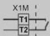
a Fire alarm input signal (potential free contact)
Remote control is available by transmission the external input to the terminals T1 and T2 on the terminal block for the user interface and the transmission wiring.
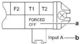
a Forced OFF b Input A
| Wiring requirements | |
| Wiring specification | Sheathed vinyl cord or 2-core cable |
| Wiring size | 0.75~1.25 mm ^2 |
| Wiring length | Maximum 100 m |
| External contact specification | Contact that can make and break the min. load of DC15 V · 1 mA |
This setting must correspond with the needs of the user.
| If you want to set... | Then^(1) | ||
| M SW — | |||
| Forced OFF | 12 (22) | 1 01 | |
| ON/OFF Operation | 02 | ||
| Emergency (recommended for alarm operation) | 03 | ||
| Forced OFF - multi tenant | 04 | ||
| Interlocking setting A | 05 | ||
| Interlocking setting B | 06 | ||
17 Technical data
- A subset of the latest technical data is available on the regional Daikin website (publicly accessible).
- The full set of latest technical data is available on the Daikin Business Portal (authentication required).
17.1 Wiring diagram
17.1.1 Unified wiring diagram legend
For applied parts and numbering, refer to the wiring diagram on the unit. Part numbering is by Arabic numbers in ascending order for each part and is represented in the overview below by "*" in the part code.
17 Technical data
| Symbol | Meaning Symbol Meaning | |
| Circuit breaker Protective earth | ||
| Connection Protective earth (screw) | ||
| Connector | Rectifier | |
| Earth Relay connector | ||
| Field wiring Short-circuit connector | ||
| Fuse Terminal | ||
| Indoor unit Terminal strip | ||
| Outdoor unit Wire clamp | ||
| Residual current device | ||
| Symbol Colour Symbol Colour | |||
| BLK Black ORG Orange | |||
| BLU Blue | PNK | Pink | |
| BRN | Brown | PRP, PPL | Purple |
| GRN | Green | RED Red | |
| GRY | Grey | WHT White | |
| SKY BLU | Sky blue | YLW Yellow | |
| Symbol | Meaning |
| A*P | Printed circuit board |
| BS* | Pushbutton ON/OFF, operation switch |
| BZ, H*O | Buzzer |
| C* | Capacitor |
| AC*, CN*, E*, HA*, HE*, HL*, HN*, HR*, MR*_A, MR*_B, S*, U, V, W, X*A, K*R_*, NE | Connection, connector |
| D*, V*D | Diode |
| DB* | Diode bridge |
| DS* | DIP switch |
| E*H | Heater |
| FU*, F*U, (for characteristics, refer to PCB inside your unit) | Fuse |
| FG* | Connector (frame ground) |
| H* | Harness |
| H*P, LED*, V*L | Pilot lamp, light emitting diode |
| HAP | Light emitting diode (service monitor green) |
| HIGH VOLTAGE High voltage | |
| IES | Intelligent eye sensor |
| IPM* | Intelligent power module |
| K*R, KCR, KFR, KHuR, K*M | Magnetic relay |
| L | Live |
| L* | Coil |
| L*R | Reactor |
| M* | Stepper motor |
| M*C | Compressor motor |
| M*F | Fan motor |
| M*P | Drain pump motor |
| M*S | Swing motor |
| Symbol | Meaning |
| MR*, MRCW*, MRM*, MRN* | Magnetic relay |
| N | Neutral |
| n=*, N=* | Number of passes through ferrite core |
| PAM | Pulse-amplitude modulation |
| PCB* | Printed circuit board |
| PM* | Power module |
| PS | Switching power supply |
| PTC* | PTC thermistor |
| Q* | Insulated gate bipolar transistor (IGBT) |
| Q*C | Circuit breaker |
| Q*DI, KLM | Earth leak circuit breaker |
| Q*L | Overload protector |
| Q*M | Thermo switch |
| Q*R | Residual current device |
| R* | Resistor |
| R*T | Thermistor |
| RC | Receiver |
| S*C | Limit switch |
| S*L | Float switch |
| S*NG | Refrigerant leak detector |
| S*NPH | Pressure sensor (high) |
| S*NPL | Pressure sensor (low) |
| S*PH, HPS* | Pressure switch (high) |
| S*PL | Pressure switch (low) |
| S*T | Thermostat |
| S*RH | Humidity sensor |
| S*W, SW* | Operation switch |
| SA*, F1S | Surge arrester |
| SR*, WLU | Signal receiver |
| SS* | Selector switch |
| SHEET METAL | Terminal strip fixed plate |
| T*R | Transformer |
| TC, TRC | Transmitter |
| V*, R*V | Varistor |
| V*R | Diode bridge, Insulated-gate bipolar transistor (IGBT) power module |
| WRC | Wireless remote controller |
| X* | Terminal |
| X*M | Terminal strip (block) |
| Y*E | Electronic expansion valve coil |
| Y*R, Y*S | Reversing solenoid valve coil |
| Z*C | Ferrite core |
| ZF, Z*F | Noise filter |

natural_image
Blank grid paper with no text, numbers, or symbols

natural_image
Blank grid paper with no text, numbers, or symbols

natural_image
Blank grid paper with no text, numbers, or symbols- Installation and operation manual
- Table of Contents
- About the documentation 4
- Specific installer safety instructions 5
- For the user 7
- User safety instructions 7
- About the system 10
- User interface 10
- Operation 10
- Maintenance and service 11
- Troubleshooting 13
- Relocation 13
- Disposal 13
- For the installer 14
- About the box 14
- Unit installation 14
- Piping installation 18
- Electrical installation 19
- Commissioning 21
- Configuration 21
- Technical data 23
- About the documentation
- About this document
- WARNING
- INFORMATION
- Target audience
- Documentation set
- Technical engineering data
- Specific installer safety instructions
- General
- Unit installation (see "12 Unit installation" [▶ 14])
- CAUTION
- Duct installation (see "12.2.2 Guidelines when installing the ducting" [▶ 16])
- Refrigerant piping installation (see "13 Piping installation" [▶ 18])
- Electrical installation (see "14 Electrical installation" [▶ 19])
- Configuration (see "16 Configuration" [▶ 21])
- Instructions for equipment using R32 refrigerant
- WARNING: MILDLY FLAMMABLE MATERIAL
- NOTICE
- Installation space requirements
- For the user
- User safety instructions
- General
- Instructions for safe operation
- CAUTION: Pay attention to the fan!
- DANGER: RISK OF ELECTROCUTION
- About the system
- System layout
- User interface
- Operation
- Operation range
- About operation modes
- Basic operation modes
- Special heating operation modes
- To operate the system
- Maintenance and service
- Precautions for maintenance and service
- Symbol Explanation
- Cleaning the air filter and air outlet
- To clean the air filter
- When to clean the air filter:
- How to clean the air filter:
- To clean the air outlet
- About the refrigerant
- About the refrigerant leakage sensor
- In case of detection when the unit is operating
- In case of detection when the unit is in standby
- False detection check
- Troubleshooting
- Relocation
- Disposal
- For the installer
- About the box
- Indoor unit
- To remove the accessories from the indoor unit
- Unit installation
- Preparing the installation site
- Installation site requirements of the indoor unit
- Minimum floor area requirements
- Service space and ceiling opening size
- Mounting the indoor unit
- Guidelines when installing the indoor unit Installation options
- Installation box for the optional output PCB
- Guidelines when installing the ducting
- Guidelines when installing the drain piping
- General guidelines
- To connect the drain piping to the indoor unit
- Drain piping connection
- Piping installation
- Drain outlet for maintenance
- Pull out the plug.
- Push in the plug.
- To check for water leaks
- When installation of the system is not yet completed
- Turn OFF the power.
- When installation of the system is already completed
- Preparing refrigerant piping
- Refrigerant piping requirements
- Refrigerant piping diameter
- Refrigerant piping material
- Refrigerant piping insulation
- Connecting the refrigerant piping
- DANGER: RISK OF BURNING/SCALDING
- To connect the refrigerant piping to the indoor unit
- Electrical installation
- Specifications of standard wiring components
- To connect the electrical wiring to the indoor unit
- Complete system example
- Commissioning
- Checklist before commissioning
- To perform a test run
- Configuration
- Field setting
- Setting: Bottom suction or rear suction installation
- To set external static pressure by the user interface
- Setting: Air volume when thermostat control is OFF
- Setting: Time to clean air filter
- Setting: Thermostat sensor selection
- Setting: Thermostat differential changeover (if remote sensor is used)
- Setting: Differential for automatic changeover
- Setting: Auto-restart after power failure
- Setting: T1/T2 input setting
- Technical data
- Wiring diagram
- Unified wiring diagram legend
Brand : DAIKIN
Model : FXMA200AXVMB
Category : Uncategorized