EKEXVA140 - Uncategorized DAIKIN - Free user manual and instructions
Find the device manual for free EKEXVA140 DAIKIN in PDF.

| Product Type | Air Conditioning Unit (Uncategorized) |
| Brand | Daikin |
| Model | EKEXVA140 |
| Power Supply | 220-240 V, 50 Hz |
| Cooling Capacity | Approx. 14,000 BTU/h (4.1 kW) |
| Heating Capacity | Approx. 16,000 BTU/h (4.7 kW) |
| Energy Efficiency Ratio (EER) | 3.2 (estimated) |
| Refrigerant | R-32 |
| Dimensions (Indoor Unit) | Approx. 900 x 300 x 250 mm |
| Dimensions (Outdoor Unit) | Approx. 800 x 600 x 300 mm |
| Weight (Indoor Unit) | Approx. 12 kg |
| Weight (Outdoor Unit) | Approx. 35 kg |
| Noise Level (Indoor) | 22-42 dB(A) |
| Noise Level (Outdoor) | 48 dB(A) |
| Functions | Cooling, Heating, Dehumidification, Fan, Auto Mode |
| Airflow Control | Auto and manual vertical/horizontal louver |
| Filter Type | Washable pre-filter, optional antibacterial filter |
| Remote Control | IR remote with LCD display |
| Wi-Fi | Optional with Daikin Online Controller |
| Maintenance | Clean filter every 2 weeks; professional check yearly |
| Safety Features | Auto restart, overheat protection, child lock |
| Spare Parts Availability | Remote control, filters, fan motor, PCBs available |
| Repairability Index | 7.5/10 (estimated based on Daikin standards) |
| Certifications | CE, RoHS, ErP compliant |
Frequently Asked Questions - EKEXVA140 DAIKIN
User questions about EKEXVA140 DAIKIN
0 question about this device. Answer the ones you know or ask your own.
Ask a new question about this device
Download the instructions for your Uncategorized in PDF format for free! Find your manual EKEXVA140 - DAIKIN and take your electronic device back in hand. On this page are published all the documents necessary for the use of your device. EKEXVA140 by DAIKIN.
USER MANUAL EKEXVA140 DAIKIN
Installation and operation manual
Option kit for combination of Daikin outdoor units with field-supplied air handling units
natural_image
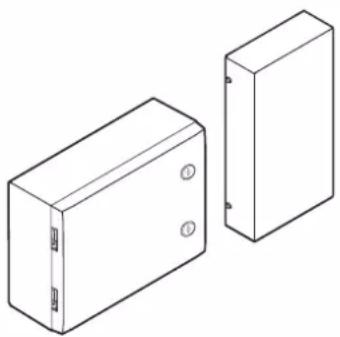
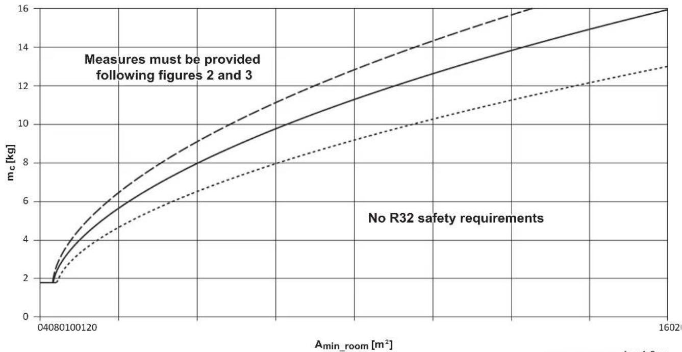
Two technical line drawings of rectangular electronic components with mounting holes (no text or symbols)1: Requirements for spaces served by AHU ( m_c ≤ 16 kg)
line
| Amin_room [m²] | mc [kg] (Solid) | mc [kg] (Dashed) | mc [kg] (Dotted) | | -------------- | --------------- | ---------------- | ---------------- | | 04080 | 2.0 | 2.0 | 2.0 | | 100120 | 4.0 | 5.0 | 3.5 | | 16020 | 16.0 | 16.0 | 13.0 |A_min_room = (m_c / (2.5 × (LFL)^(5/4) × h_0))^2,
but not less than A_min_room = m_c / (50% LFL × h_0) (valid for m_c > 1.84 kg )
h0=1.8 m
h_0=2.2 m
- - - - - - h_0=2.5 m
| m_c[kg] | m[m^2]_0=1.8 m)(h) | m[m^2]_0=2.2 m)(h) | m[m^2]_0=2.5 m)(h) |
| 2 | 4.9 | 4.0 | 3.5 |
| 2.5 | 6.1 | 5.0 | 4.4 |
| 3 | 8.6 | 6.0 | 5.3 |
| 3.5 | 11.6 | 7.8 | 6.1 |
| 4 | 15.2 | 10.2 | 7.9 |
| 4.5 | 19.2 | 12.9 | 10.0 |
| 5 | 23.7 | 15.9 | 12.3 |
| 5.5 | 28.7 | 19.2 | 14.9 |
| 6 | 34.1 | 22.8 | 17.7 |
| 6.5 | 40.0 | 26.8 | 20.8 |
| 7 | 46.4 | 31.1 | 24.1 |
| 7.5 | 53.2 | 35.7 | 27.6 |
| 8 | 60.6 | 40.6 | 31.4 |
| 8.5 | 68.4 | 45.8 | 35.5 |
| 9 | 76.6 | 51.3 | 39.8 |
| 9.5 | 85.4 | 57.2 | 44.3 |
| 10 | 94.6 | 63.4 | 49.1 |
| 10.5 | 104.3 | 69.8 | 54.1 |
| 11 | 114.5 | 76.6 | 59.4 |
| 11.5 | 125.1 | 83.8 | 64.9 |
| 12 | 136.2 | 91.2 | 70.6 |
| 12.5 | 147.8 | 99.0 | 76.6 |
| 13 | 159.9 | 107.0 | 82.9 |
| 13.5 | 172.4 | 115.4 | 89.4 |
| 14 | 185.4 | 124.1 | 96.1 |
| 14.5 | 198.9 | 133.1 | 103.1 |
| 15 | 212.8 | 142.5 | 110.4 |
| 15.5 | 227.2 | 152.1 | 117.8 |
| 16 | 242.1 | 162.1 | 125.5 |
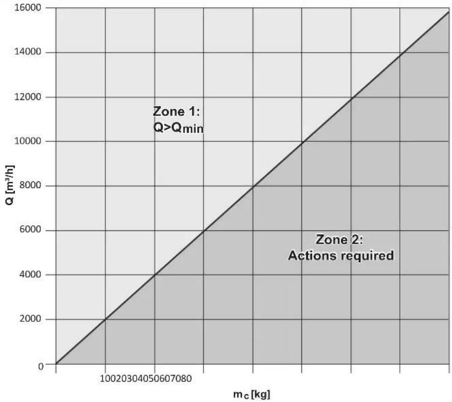
2: Minimum circulation airflow
line
| m_c [kg] | Q [m³/h] | | -------- | -------- | | 0 | 0 | | 10020304050607080 | 2000 | | 10020304050607080 | 4000 | | 10020304050607080 | 6000 | | 10020304050607080 | 8000 | | 10020304050607080 | 10000 | | 10020304050607080 | 12000 | | 10020304050607080 | 14000 | | 10020304050607080 | 16000 |Q_min = 60× m / LFL
| m_c [kg] | Q_min [ m^3/h ] |
| 0 | 0.0 |
| 0.5 | 97.7 |
| 1 | 195.4 |
| 1.5 | 293.2 |
| 2 | 390.9 |
| 2.5 | 488.6 |
| 3 | 586.3 |
| 3.5 | 684.0 |
| 4 | 781.8 |
| 4.5 | 879.5 |
| 5 | 977.2 |
| 5.5 | 1074.9 |
| 6 | 1172.6 |
| 6.5 | 1270.4 |
| 7 | 1368.1 |
| 7.5 | 1465.8 |
| 8 | 1563.5 |
| 8.5 | 1661.2 |
| 9 | 1759.0 |
| 9.5 | 1856.7 |
| 10 | 1954.4 |
| 10.5 | 2052.1 |
| 11 | 2149.8 |
| 11.5 | 2247.6 |
| 12 | 2345.3 |
| 12.5 | 2443.0 |
| 13 | 2540.7 |
| 13.5 | 2638.4 |
| 14 | 2736.2 |
| 14.5 | 2833.9 |
| 15 | 2931.6 |
| 15.5 | 3029.3 |
| 16 | 3127.0 |
| 16.5 | 3224.8 |
| 17 | 3322.5 |
| 17.5 | 3420.2 |
| 18 | 3517.9 |
| 18.5 | 3615.6 |
| 19 | 3713.4 |
| 19.5 | 3811.1 |
| m_c [kg] | Q_min [ m^3/h ] |
| 20 | 3908.8 |
| 20.5 | 4006.5 |
| 21 | 4104.2 |
| 21.5 | 4202.0 |
| 22 | 4299.7 |
| 22.5 | 4397.4 |
| 23 | 4495.1 |
| 23.5 | 4592.8 |
| 24 | 4690.6 |
| 24.5 | 4788.3 |
| 25 | 4886.0 |
| 25.5 | 4983.7 |
| 26 | 5081.4 |
| 26.5 | 5179.2 |
| 27 | 5276.9 |
| 27.5 | 5374.6 |
| 28 | 5472.3 |
| 28.5 | 5570.0 |
| 29 | 5667.8 |
| 29.5 | 5765.5 |
| 30 | 5863.2 |
| 30.5 | 5960.9 |
| 31 | 6058.6 |
| 31.5 | 6156.4 |
| 32 | 6254.1 |
| 32.5 | 6351.8 |
| 33 | 6449.5 |
| 33.5 | 6547.2 |
| 34 | 6645.0 |
| 34.5 | 6742.7 |
| 35 | 6840.4 |
| 35.5 | 6938.1 |
| 36 | 7035.8 |
| 36.5 | 7133.6 |
| 37 | 7231.3 |
| 37.5 | 7329.0 |
| 38 | 7426.7 |
| 38.5 | 7524.4 |
| 39 | 7622.1 |
| 39.5 | 7719.9 |
| mc [kg] | Q_ m^3/h |
| 40 | 7817.6 |
| 40.5 | 7915.3 |
| 41 | 8013.0 |
| 41.5 | 8110.7 |
| 42 | 8208.5 |
| 42.5 | 8306.2 |
| 43 | 8403.9 |
| 43.5 | 8501.6 |
| 44 | 8599.3 |
| 44.5 | 8697.1 |
| 45 | 8794.8 |
| 45.5 | 8892.5 |
| 46 | 8990.2 |
| 46.5 | 9087.9 |
| 47 | 9185.7 |
| 47.5 | 9283.4 |
| 48 | 9381.1 |
| 48.5 | 9478.8 |
| 49 | 9576.5 |
| 49.5 | 9674.3 |
| 50 | 9772.0 |
| 50.5 | 9869.7 |
| 51 | 9967.4 |
| 51.5 | 10065.1 |
| 52 | 10162.9 |
| 52.5 | 10260.6 |
| 53 | 10358.3 |
| 53.5 | 10456.0 |
| 54 | 10553.7 |
| 54.5 | 10651.5 |
| 55 | 10749.2 |
| 55.5 | 10846.9 |
| 56 | 10944.6 |
| 56.5 | 11042.3 |
| 57 | 11140.1 |
| 57.5 | 11237.8 |
| 58 | 11335.5 |
| 58.5 | 11433.2 |
| 59 | 11530.9 |
| 59.5 | 11628.7 |
| m_c [kg] | Q_min [m3/h] |
| 60 | 11726.4 |
| 60.5 | 11824.1 |
| 61 | 11921.8 |
| 61.5 | 12019.5 |
| 62 | 12117.3 |
| 62.5 | 12215.0 |
| 63 | 12312.7 |
| 63.5 | 12410.4 |
| 64 | 12508.1 |
| 64.5 | 12605.9 |
| 65 | 12703.6 |
| 65.5 | 12801.3 |
| 66 | 12899.0 |
| 66.5 | 12996.7 |
| 67 | 13094.5 |
| 67.5 | 13192.2 |
| 68 | 13289.9 |
| 68.5 | 13387.6 |
| 69 | 13485.3 |
| 69.5 | 13583.1 |
| 70 | 13680.8 |
| 70.5 | 13778.5 |
| 71 | 13876.2 |
| 71.5 | 13973.9 |
| 72 | 14071.7 |
| 72.5 | 14169.4 |
| 73 | 14267.1 |
| 73.5 | 14364.8 |
| 74 | 14462.5 |
| 74.5 | 14560.3 |
| 75 | 14658.0 |
| 75.5 | 14755.7 |
| 76 | 14853.4 |
| 76.5 | 14951.1 |
| 77 | 15048.9 |
| 77.5 | 15146.6 |
| 78 | 15244.3 |
| 78.5 | 15342.0 |
| 79 | 15439.7 |
| 79.82 | 15600.0 |
3a: Requirements for AHU installation location
(only applicable for indoor installations)
3b: Requirements for spaces served by AHU
line
| Ainst [m²] | mc [kg] | | ---------- | ------- | | 050 | 0 | | 100 | 10 | | 125 | 20 | | 150 | 30 | | 200 | 40 | | 250 | 50 | | 300 | 60 | | 350 | 70 | | 400 | 80 | | 450 | 90 | | 500 | 100 | | 550 | 110 | | 600 | 120 | | 650 | 130 | | 700 | 140 | | 750 | 150 | | 800 | 160 | | 850 | 170 | | 900 | 180 | | 950 | 190 | | 1000 | 200 | | 1050 | 210 | | 1100 | 220 | | 1150 | 230 | | 1200 | 240 | | 1250 | 250 | | 1300 | 260 | | 1350 | 270 | | 1400 | 280 | | 1450 | 290 | | 1500 | 300 | | 1550 | 310 | | 1600 | 320 | | 1650 | 330 | | 1700 | 340 | | 1750 | 350 | | 1800 | 360 | | 1850 | 370 | | 1900 | 380 | | 1950 | 390 | | 2000 | 400 | | 2050 | 410 | | 2100 | 420 | | 2150 | 430 | | 2200 | 440 | | 2250 | 450 | | 2300 | 460 | | 2350 | 470 | | 2400 | 480 | | 2450 | 490 | | 2500 | 500 | | 2550 | 510 | | 2600 | 520 | | 2650 | 530 | | 2700 | 540 | | 2750 | 550 | | 2800 | 560 | | 2850 | 570 | | 2900 | 580 | | 2950 | 590 | | 3000 | 600 | | 3050 | 610 | | 3100 | 620 | | 3150 | 630 | | 3200 | 640 | | 3250 | 650 | | 3300 | 660 | | 3350 | 670 | | 3400 | 680 | | 3450 | 690 | | 3500 | 700 | | 3550 | 710 | | 3600 | 720 | | 3650 | 730 | | 3700 | 740 | | 3750 | 750 | | 3800 | 760 | | 3850 | 770 | | 3900 | 780 | | 3950 | 790 | | 4000 | 800 | Zone Point: No action required Zone Point: No action required Zone Point: No action required Zone Point: No action required Zone Point: No action required Zone Point: No action required Zone Point: No action required Zone Point: No action required Zone Point: No action required Zone Point: No action required Zone Point: No action required Zone Point: No action required Zone Point: No action required Zone Point: No action required Zone Point: No action required Zone Points: Zone points Zone Points: Zone points Zone Points: Zone points Zone Points: Zone points Zone Points: Zone points Zone Points: Zone points Zone Points: Zone points Zone Points: Zone points Zone Points: Zone points Zone Points: Zone points Zone Points: Zone points Zone Points: Zone points Zone Points: Zone points Zone Points: Zone points Zone Points: Zone points Zone Points: Zone points Zone Points: Zone points Zone Points: Zone Points: Zone Points: Zone Points: Zone Points: Zone Points: Zone Points: Zone Points: Zone Points: Zone Points: Zone Points: Zone Points: Zone Points: Zone Points: Zone Points: Zone Points: Zone Points: Zone Points: Zone Points: Zone Points: Zone Points: Zone Points: Zone Points: Zone Points: Zone Points: Zone Points: Zone Points: Zone Points: Zone Points: Zone Points: Zone Points: Zone Points: Zone Points: Zone Points: Range from Range [m²] to Range [m²] for Zone Point [m²] to Range [m²].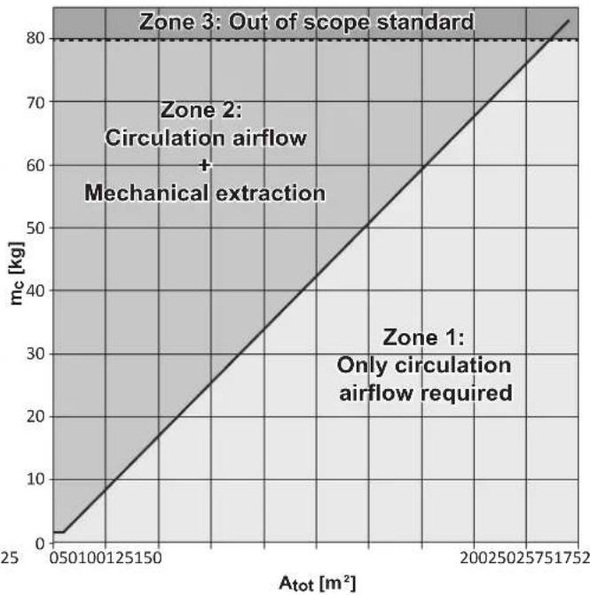
line
| Atot [m²] | mc [kg] | | --------- | ------- | | 050 | 0 | | 100 | 10 | | 125 | 20 | | 150 | 30 | | 200 | 40 | | 250 | 50 | | 275 | 60 | | 317 | 70 | | 357 | 80 |50%LFL×H×(A tot or A Inst ) (valid for m _c >1.84 kg) 260LFL
| A_10r A[m^2] | m_c [kg] |
| 6 | 2.0 |
| 10 | 3.4 |
| 15 | 5.1 |
| 20 | 6.8 |
| 25 | 8.4 |
| 30 | 10.1 |
| 35 | 11.8 |
| 40 | 13.5 |
| 45 | 15.2 |
| 50 | 16.9 |
| 55 | 18.6 |
| 60 | 20.3 |
| 65 | 22.0 |
| 70 | 23.6 |
| 75 | 25.3 |
| 80 | 27.0 |
| 85 | 28.7 |
| 90 | 30.4 |
| 95 | 32.1 |
| 100 | 33.8 |
| 105 | 35.5 |
| 110 | 37.1 |
| 115 | 38.8 |
| 120 | 40.5 |
| tot A_inst [ m^2 ] | A orm _c [kg] |
| 125 | 42.2 |
| 130 | 43.9 |
| 135 | 45.6 |
| 140 | 47.3 |
| 145 | 49.0 |
| 150 | 50.7 |
| 155 | 52.3 |
| 160 | 54.0 |
| 165 | 55.7 |
| 170 | 57.4 |
| 175 | 59.1 |
| 180 | 60.8 |
| 185 | 62.5 |
| 190 | 64.2 |
| 195 | 65.9 |
| 200 | 67.5 |
| 205 | 69.2 |
| 210 | 70.9 |
| 215 | 72.6 |
| 220 | 74.3 |
| 225 | 76.0 |
| 230 | 77.7 |
| 235 | 79.4 |
| 236 | 79.7 |
Table of contents
1 About this document 5
1.1 Meaning of warnings and symbols 6
2 Specific installer safety instructions 6
2.1 Instructions for equipment using R32 refrigerant .... 7
For the user 7
3 User safety instructions 7
3.1 General....7
3.2 Instructions for safe operation 8
4 About the system 8
4.1 System layout....8
5 Operation 8
6 Maintenance and service 8
7 Troubleshooting 9
8 Relocation 9
9 Disposal 9
For the installer 9
10 About the box 9
10.1 Control box.... 9
10.1.1 To remove the accessories from the control box..... 9
10.2 Expansion valve kit.... 10
10.2.1 To remove the accessories from the expansion valve kit 10
11 About the system 10
11.1 System layout.... 10
11.1.1 Pair AHU layout 10
11.1.2 Multi AHU layout 11
11.1.3 Mixed AHU layout 11
11.2 Possible control types 11
11.2.1 X control: Operation with 0-10 V DC capacity control. 11
11.2.2 Y control: Operation with fixed Te/Tc temperature control 12
11.2.3 W control: Operation with 0-10 V DC capacity control 12
11.2.4 Z control: Suction air control 12
11.2.5 Z' control: Discharge air control 13
11.3 Operation signals 13
11.4 Remote controller for EKEA 13
11.5 Selection of the expansion valve kit 14
11.6 Outdoor unit.... 14
11.6.1 Possible outdoor units.... 14
11.6.2 ERQ outdoor units 14
11.6.3 VRV outdoor units.... 14
11.7 Air handling unit.... 14
11.8 Connection ratio and heat exchanger volume limitations.... 15
11.9 Master-slave configuration 15
11.9.1 Combined refrigerant circuit system 16
11.9.2 Separate refrigerant circuits system 17
12 Special requirements for R32 units 17
12.1 Conditioned space requirements.... 18
12.2 Determination of the safety requirements 18
12.2.1 Example 1 18
12.2.2 Example 2.... 18
12.2.3 Example 3.... 19
13 Unit installation 19
13.1 Control box 19
13.1.1 Installation site requirements of the control box.... 19
13.1.2 To install the control box 20
13.2 Expansion valve kit.... 20
13.2.1 Installation site requirements of the expansion valve kit 20
13.2.2 To install the expansion valve kit 20
13.3 Thermistors 20
13.3.1 Location of the thermistors.... 20
13.3.2 To install the thermistor cable.... 21
13.3.3 To install a longer thermistor cable 21
13.3.4 To fix the thermistor 21
14 Piping installation 22
14.1 Preparing refrigerant piping 22
14.1.1 Refrigerant piping requirements.... 22
14.1.2 Refrigerant piping insulation 22
14.2 Connecting the refrigerant piping 22
14.2.1 To connect the refrigerant piping 22
14.2.2 To braze the pipe end 23
15 Electrical installation 23
15.1 Control box 23
15.1.1 To connect the electrical wiring to the control box..... 23
15.2 Expansion valve kit.... 26
15.2.1 To connect the electrical wiring to the expansion valve kit 26
16 Configuration 27
16.1 To configure the control box.... 27
16.2 Field settings 29
17 Commissioning 30
17.1 Checklist before commissioning.... 30
17.2 To check during normal operation 30
18 Troubleshooting 30
18.1 Solving problems based on error codes.... 30
18.1.1 Error codes: Overview 31
18.2 Symptom: The AHU heat exchanger is freezing up 31
19 Technical data 31
19.1 Wiring diagram 31
20 Glossary 32
1 About this document

WARNING
Make sure installation, servicing, maintenance, repair and applied materials follow the instructions from Daikin (including all documents listed in "Documentation set") and, in addition, comply with applicable legislation (for example national gas regulation) and are performed by qualified persons only. In Europe and areas where IEC standards apply, EN/IEC 60335-2-40 is the applicable standard.

INFORMATION
Make sure that the user has the printed documentation and ask him/her to keep it for future reference.
Target audience
Authorised installers + end users

INFORMATION
This appliance is intended to be used by expert or trained users in shops, in light industry and on farms, or for commercial use by lay persons.
2 Specific installer safety instructions
Documentation set
This document is part of a documentation set. The complete set consists of:
- Installation and operation manual:
- Installation and operation instructions for the control box
- Installation instructions for the expansion valve kit
- Format: paper (in the box of the control box)
Latest revisions of the supplied documentation may be available on the regional Daikin website or via your dealer.
The original instructions are written in English. All other languages are translations of the original instructions.
Technical engineering data
- A subset of the latest technical data is available on the regional Daikin website (publicly accessible).
- The full set of latest technical data is available on the Daikin Business Portal (authentication required).
1.1 Meaning of warnings and symbols

DANGER
Indicates a situation that results in death or serious injury.

DANGER: RISK OF ELECTROCUTION
Indicates a situation that could result in electrocution.

DANGER: RISK OF BURNING/SCALDING
Indicates a situation that could result in burning/scalding because of extreme hot or cold temperatures.

DANGER: RISK OF EXPLOSION
Indicates a situation that could result in explosion.

WARNING
Indicates a situation that could result in death or serious injury.

WARNING: FLAMMABLE MATERIAL

WARNING: MILDLY FLAMMABLE MATERIAL
The refrigerant inside this unit is mildly flammable.

CAUTION
Indicates a situation that could result in minor or moderate injury.

NOTICE
Indicates a situation that could result in equipment or property damage.

INFORMATION
Indicates useful tips or additional information.
Symbols used on the unit:
Symbol Explanation

Before installation, read the installation and operation manual, and the wiring instruction sheet.

Before performing maintenance and service tasks, read the service manual.
2 Specific installer safety instructions
Always observe the following safety instructions and regulations.
General

WARNING
Make sure installation, servicing, maintenance and repair comply with instructions from Daikin and with applicable legislation (for example national gas regulation) and are executed ONLY by authorised persons.
Unit installation (see "13 Unit installation" [▶ 19])
![DAIKIN EKEXVA140 - Unit installation (see "13 Unit installation" [▶ 19]) - 1](/content/2026/05/852315/images/e52dc860cbd8a2691cb79e2bfdb03f209aeb0bfd04858e3a3ac77e2f3a587b87.jpg)
WARNING
The fixing method MUST be in accordance with the instructions from this manual. See "13 Unit installation" [▶ 19].
Refrigerant piping installation (see "14 Piping installation" [▶ 22])
![DAIKIN EKEXVA140 - Refrigerant piping installation (see "14 Piping installation" [▶ 22]) - 1](/content/2026/05/852315/images/1a723fa4e28223667148c022327df30737be2199786b8c5c1813cf7729d89a82.jpg)
WARNING
The field piping method MUST be in accordance with the instructions from this manual. See "14 Piping installation" [▶ 22].

WARNING
Only systems using R32 or R410A refrigerant can be used with the control box (EKEA) and the expansion valve kit (EKEXVA).

CAUTION
Install the refrigerant piping or components in a position where they are unlikely to be exposed to any substance which may corrode components containing refrigerant, unless the components are constructed of materials that are inherently resistant to corrosion or are suitably protected against corrosion.
Electrical installation (see "15 Electrical installation" [▶ 23])
![DAIKIN EKEXVA140 - Electrical installation (see "15 Electrical installation" [▶ 23]) - 1](/content/2026/05/852315/images/50695ede1c1fa96798964f2ab3bba853da1de573891f374ef839e85365934615.jpg)
WARNING
The electrical wiring connection method MUST be in accordance with the instructions from this manual. See "15 Electrical installation" [▶23].

DANGER: RISK OF ELECTROCUTION

WARNING
- All wiring MUST be performed by an authorised electrician and MUST comply with the applicable national wiring regulation.
- Make electrical connections to the fixed wiring.
- All components procured on-site and all electrical construction MUST comply with the applicable legislation.

WARNING
ALWAYS use multicore cable for power supply cables.

WARNING
Use an all-pole disconnection type breaker with at least 3 mm between the contact point gaps that provides full disconnection under overvoltage category III.

WARNING
- If the power supply has a missing or wrong N-phase, equipment might break down.
- Establish proper earthing. Do NOT earth the unit to a utility pipe, surge absorber, or telephone earth. Incomplete earthing may cause electrical shocks.
- Install the required fuses or circuit breakers.
- Secure the electrical wiring with cable ties so that the cables do NOT come in contact with sharp edges or piping.
- Do NOT use taped wires, extension cords, or connections from a star system. They can cause overheating, electrical shocks or fire.

WARNING
If the supply cord is damaged, it MUST be replaced by the manufacturer, its service agent or similarly qualified persons in order to avoid a hazard.
Commissioning (see "17 Commissioning" [▶ 30])

WARNING
Commissioning method MUST be in accordance with the instructions from this manual. See "17 Commissioning" [▶ 30].
2.1 Instructions for equipment using R32 refrigerant

WARNING
- Do NOT pierce or burn refrigerant cycle parts.
- Do NOT use cleaning materials or means to accelerate the defrosting process other than those recommended by the manufacturer.
- Be aware that the refrigerant inside the system is odourless.

WARNING
The appliance shall be stored as follows:
- in such a way as to prevent mechanical damage.
- in a well-ventilated room without continuously operating ignition sources (example: open flames, an operating gas appliance or an operating electric heater).

WARNING
Make sure installation, servicing, maintenance and repair comply with instructions from Daikin and with applicable legislation (for example national gas regulation) and are executed ONLY by authorised persons.

WARNING
- Take precautions to avoid excessive vibration or pulsation to refrigeration piping.
- Protect the protection devices, piping and fittings as much as possible against adverse environmental effects.
- Provide space for expansion and contraction of long runs of piping.
- Design and install piping in refrigerating systems such as to minimise the likelihood of hydraulic shock damaging the system.
- Mount the indoor equipment and pipes securely and protect them to avoid accidental rupture of equipment or pipes in case of events such as moving furniture or reconstruction activities.

WARNING
For the determination of the total conditioned space area, only consider spaces that are continuously served. Spaces where the airflow rate can be limited by zoning dampers must NOT be included in the determination of the total area. Only exceptions are zoning dampers used specifically for fire safety.

CAUTION
Do NOT use potential sources of ignition in searching for or detection of refrigerant leaks.

NOTICE
- The pipework shall be securely mounted and guarded protected from physical damage.
- Keep the pipework installation to a minimum.

NOTICE
- Do NOT re-use joints and copper gaskets which have been used already.
- Joints made in the installation between parts of the refrigerant system shall be accessible for maintenance purposes.
For the user
3 User safety instructions
Always observe the following safety instructions and regulations.
3.1 General

WARNING
If you are NOT sure how to operate the unit, contact your installer.

WARNING
This appliance can be used by children aged from 8 years and above and persons with reduced physical, sensory or mental capabilities or lack of experience and knowledge if they have been given supervision or instruction
4 About the system
concerning use of the appliance in a safe way and understand the hazards involved.
Children SHALL NOT play with the appliance.
Cleaning and user maintenance SHALL NOT be made by children without supervision.

WARNING
To prevent electrical shocks or fire:
- Do NOT rinse the unit.
- Do NOT operate the unit with wet hands.
- Do NOT place any objects containing water on the unit.

CAUTION
- Do NOT place any objects or equipment on top of the unit.
- Do NOT sit, climb or stand on the unit.
- Units are marked with the following symbol:
This means that electrical and electronic products may NOT be mixed with unsorted household waste. Do NOT try to dismantle the system yourself: dismantling the system, treatment of the refrigerant, of oil and of other parts MUST be done by an authorised installer and MUST comply with applicable legislation.
Units MUST be treated at a specialised treatment facility for reuse, recycling and recovery. By ensuring this product is disposed of correctly, you will help to prevent potential negative consequences for the environment and human health. For more information, contact your installer or local authority.
3.2 Instructions for safe operation

CAUTION
Do NOT leave the front door of the EKEA control box open. Some parts inside are dangerous to touch and appliance problems may occur. For checking and adjusting the internal parts, contact your dealer.
4 About the system

WARNING: MILDLY FLAMMABLE MATERIAL
The R32 refrigerant (if applicable) in this unit is mildly flammable. Refer to the outdoor unit specifications for the type of refrigerant to be used.
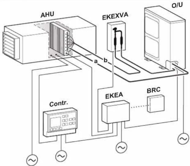
4.1 System layout

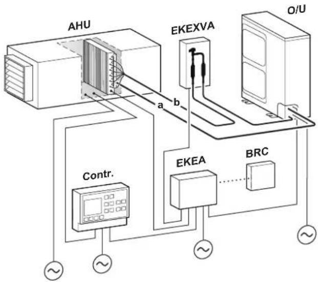
INFORMATION
The following figure is an example and may NOT completely match your system layout
flowchart
graph TD
    A["AHU"] -->|a| B["EKEXVA"]
    B -->|b| C["O/U"]
    D["Contr."] -->|~| E["AC Unit"]
    F["EKEA"] --> G["BRC"]
    G --> H["~"]
    I["~"] --> J["~"]
    K["~"] --> L["~"]
a Gas piping (field supply)
b Liquid piping (field supply)
AHU Air handling unit (field supply)
BRC Wired remote controller
Contr. Controller (field supply)
EKEA Control box
EKEXVA Expansion valve kit
O/U Outdoor unit

INFORMATION
- This equipment is not designed for year-round cooling applications with low indoor humidity conditions, such as Electronic Data Processing rooms.
- Combination of EKEA + EKEXVA + AHU is not a comfort product.
5 Operation
The operating temperature of the control box and the expansion valve kit is between -20^ and 52^ .
6 Maintenance and service

WARNING
- Only qualified service persons are allowed to perform maintenance.
- Before obtaining access to terminal devices, all power supply circuits must be interrupted.
- Water or detergent may deteriorate the insulation of electronic components and result in burn-out of these components.
7 Troubleshooting
To set up the system and make troubleshooting possible, it is required to connect the remote controller to the control box.
If one of the following malfunctions occurs, take the measures shown below and contact your dealer.
The system MUST be repaired by a qualified service person.
| Malfunction Measure | |
| If a safety device such as a fuse, a circuit breaker or a residual current device frequently actuates or the ON/OFF switch does NOT function properly. | Turn OFF all main power supply switches to the unit. |
| If water leaks from the unit. Stop operation. | |
| The operation switch does NOT function properly. | Turn OFF the power supply. |
| If the user interface displays | Notify your installer and report the error code. To display an error code see the reference guide of the user interface. |
If the system does NOT operate properly except for the above mentioned cases and none of the above mentioned malfunctions is evident, investigate the system in accordance with the following procedures.
| Malfunction Measure | |
| The system does not operate at all. | Check if there is a power failure. Wait until power is restored. If power failure occurs during operation, the system automatically restarts immediately after power is restored.Check if a fuse has blown or circuit breaker is activated. Change the fuse or reset the breaker if necessary. |
| Malfunction Measure | |
| The system stops immediately after starting operation | ·Check if the air inlet or outlet of the air handling unit or outdoor unit is blocked by obstacles. Remove any obstacles and make sure the air can flow freely.·Check if the air filter is clogged. Contact your dealer to clean the air filter.·The error signal is given and the system stops. If the error resets after 5-10 minutes, the unit safety device was activated but the unit restarted after evaluation time. If the error persists, contact your dealer. |
| The system operates but cooling or heating is insufficient. | ·Check if the air inlet or outlet of the air handling unit or outdoor unit is blocked by obstacles. Remove any obstacles and make sure the air can flow freely.·Check if the air filter is clogged. Contact your dealer to clean the air filter. |
8 Relocation
Contact your dealer to remove and reinstall the entire unit. Moving units requires technical expertise.
9 Disposal

NOTICE
Do NOT try to dismantle the system yourself: dismantling of the system, treatment of the refrigerant, oil and other parts MUST comply with applicable legislation. Units MUST be treated at a specialised treatment facility for reuse, recycling and recovery.
For the installer
10 About the box
10.1 Control box
10.1.1 To remove the accessories from the control box
Make sure that all accessories are available in the control box.
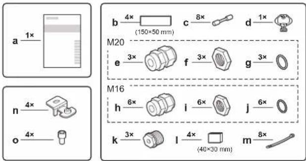
a Installation and operational manual
b Insulation tape for thermistors
c Wire-to-wire splice
d Box opening key
e Cable gland (M20)
f Nut (M20)
g O-ring (∅20 mm)
h Cable gland (M16)
11 About the system
i Nut (M16)
J O-ring (∅16 mm)
k Stopper for unused cable opening
I Insulation rubber for thermistors
m Cable tie
n Hanger bracket
- Screw for hanger bracket
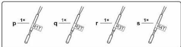
p R1T: Thermistor (suction air)
q R2T: Thermistor (liquid pipe)
r R3T: Thermistor (gas pipe)
s R4T: Thermistor (discharge air)
10.2 Expansion valve kit
10.2.1 To remove the accessories from the expansion valve kit
Make sure that all accessories are available in the expansion valve kit.
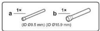
a Transition pipe (inside diameter 9.5 mm)
b Transition pipe (inside diameter 15.9 mm)
You only need to use a transition pipe for certain expansion valve kits in case of R410A. See "Refrigerant piping diameter" [▶ 22].
11 About the system

WARNING: MILDLY FLAMMABLE MATERIAL
The R32 refrigerant (if applicable) in this unit is mildly flammable. Refer to the outdoor unit specifications for the type of refrigerant to be used.
11.1 System layout

WARNING
In case of R32 refrigerant, the installation MUST comply with the requirements that apply to this R32 equipment. For more information, see:
- "2.1 Instructions for equipment using R32 refrigerant" [▶ 7]
- "12 Special requirements for R32 units" [▶ 17]

INFORMATION
The following figure is an example and may NOT completely match your system layout
flowchart
graph TD
    A["AHU"] -->|a| B["EKEXVA"]
    B -->|b| C["Contr."]
    C --> D["EKEA"]
    D --> E["BRC"]
    E --> F["~"]
    style A fill:#f9f,stroke:#333
    style B fill:#ccf,stroke:#333
    style C fill:#cfc,stroke:#333
    style D fill:#fcc,stroke:#333
    style E fill:#cff,stroke:#333
    style F fill:#ffc,stroke:#333
a Gas piping (field supply)
b Liquid piping (field supply)
AHU Air handling unit (field supply)
BRC Wired remote controller
Contr. Controller (field supply)
EKEA Control box
EKEXVA Expansion valve kit
O/U Outdoor unit
11.1.1 Pair AHU layout
In a pair AHU layout, there is one air handling unit, one or more expansion valve kits, and one or more outdoor units. There are 3 possible pair AHU layouts.
Pair AHU layout 1
One air handling unit, one expansion valve kit, and one outdoor unit.
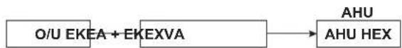
AHU Air handling unit
AHU HEX Heat exchanger of the air handling unit
EKEA Control box
EKEXVA Expansion valve kit
O/U Outdoor unit
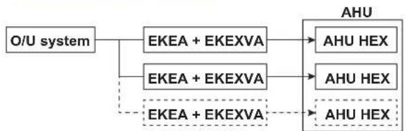
Pair AHU layout 2
One air handling unit with an interlaced heat exchanger, two or three expansion valve kits, and one outdoor unit system (meaning one or more outdoor units that are connected to the same refrigerant circuit).
Note: In case of interlaced heat exchangers, the number of field wires can be reduced by using a master-slave configuration. See "11.9 Master-slave configuration" [▶ 15].
flowchart
graph TD
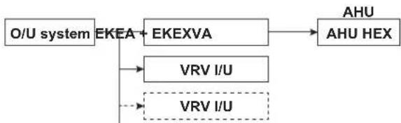
A["O/U system"] --> B["EKEA + EKEXVA"]
A --> C["EKEA + EKEXVA"]
B --> D["AHU HEX"]
C --> E["AHU HEX"]
F["EKEA + EKEXVA"] -.-> G["AHU HEX"]
AHU Air handling unit
AHU HEX Heat exchanger of the air handling unit
EKEA Control box
EKEXVA Expansion valve kit
O/U system Outdoor unit system
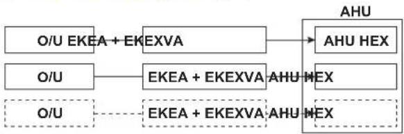
Pair AHU layout 3
One air handling unit with an interlaced heat exchanger, two or more expansion valve kits, each individually connected to separate outdoor units. There is no refrigerant connection between the outdoor units.
Note: In case of interlaced heat exchangers, the number of field wires can be reduced by using a master-slave configuration. See "11.9 Master-slave configuration" [▶ 15].
flowchart
graph LR
    A["O/U EKEA + EKEXVA"] --> B["AHU"]
    C["O/U"] --> D["EKEA + EKEXVA AHU MEX"]
    E["O/U"] -.-> F["EKEA + EKEXVA AHU MEX"]
    B --> G["AHU HEX"]
    D --> H["AHU MEX"]
    F --> I["AHU MEX"]
AHU Air handling unit AHU HEX Heat exchanger of the air handling unit EKEA Control box EKEXVA Expansion valve kit O/U Outdoor unit
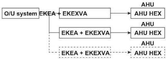
11.1.2 Multi AHU layout
In a multi AHU layout, there are several air handling units, each with a separate expansion valve kit, connected to one outdoor unit system (meaning one or more outdoor units that are connected to the same refrigerant circuit).
flowchart
graph TD
    A["O/U system"] --> B["EKEA"]
    B --> C["EKEXVA"]
    C --> D["AHU"]
    B --> E["EKEA + EKEXVA"]
    E --> F["AHU"]
    E --> G["AHU + EKEXVA"]
    G --> H["AHU HEX"]
AHU Air handling unit AHU HEX Heat exchanger of the air handling unit EKEA Control box EKEXVA Expansion valve kit /U system Outdoor unit system
11.1.3 Mixed AHU layout
In a mixed AHU layout, there are one or more air handling units, each with a separate expansion valve kit, connected to one outdoor unit system (meaning one or more outdoor units that are connected to the same refrigerant circuit). Next to the expansion valve kits, also normal VRV indoor units are connected to the same outdoor unit system.
flowchart
graph TD
    A["O/U system"] --> B["EKEA"]
    B --> C["EKEXVA"]
    C --> D["AHU"]
    C --> E["AHU HEX"]
    B --> F["VRV I/U"]
    B --> G["VRV I/U"]
AHU Air handling unit
AHU HEX Heat exchanger of the air handling unit
EKEA Control box
EKEXVA Expansion valve kit
/U system Outdoor unit system
VRV I/U VRV indoor unit
11.2 Possible control types
Field-supplied air handling units can be connected with a Daikin VRV outdoor unit via a control box and expansion valve kit. Each air handling unit must be connected with at least 1 control box and 1 expansion valve kit (in case of interlaced heat exchanger applications, multiple control boxes per air handling unit are possible, see "11.9 Master-slave configuration" [▶ 15]).
The control box allows regulating the capacity of the air handling unit in cooling and heating, using 5 possible control types:
| Control type | Layout | |
| Pair | Multi/mix | |
| X control | ● | — |
| Control type | Layout | |
| Pair | Multi/mix | |
| Y control | ● | — |
| W control | ● | — |
| Z control | ● | ● |
| Z' control | ● | ● |
• Applicable — Not applicable
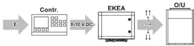
11.2.1 X control: Operation with 0-10 V DC capacity control
For X control, a controller (field supply) needs to be connected to the EKEA control box. The controller will generate a 0–10 V DC signal that will be used by the EKEA control box for the capacity control of the system.
flowchart
graph LR
    T --> Contr.
    Contr. --> EKEA
    EKEA --> O/U
    style Contr. fill:#f9f,stroke:#333
    style EKEA fill:#ccf,stroke:#333
    style O/U fill:#cfc,stroke:#333
Contr. Controller (field supply) EKEA Control box O/U Outdoor unit ↑↑, ↑, →, ↓, ↓↓ Capacity request sent to the outdoor unit via F1F2 0-10 V DC Voltage signal T Temperature
The system needs a controller (field supply) with a temperature sensor. The temperature sensor can be used to control the following temperatures:
- Suction air temperature of the air handling unit
- Room air temperature
- Discharge air temperature of the air handling unit
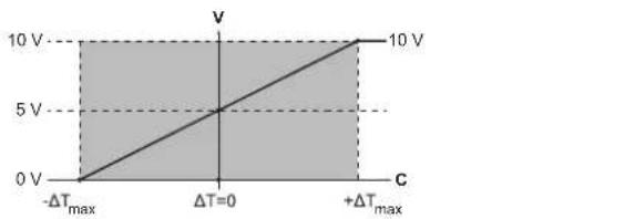
Program the controller (field supply) so that it outputs a 0–10 V DC signal based on the temperature difference between the actual measured temperature and the target temperature.
line
| C | V | |---|---| | -ΔT_max | 0 | | ΔT=0 | 5 | | +ΔT_max | 10 |V Controller (field supply) voltage output to EKEA ΔT [actual measured temperature]–[target temperature] When ΔT=0, the target temperature is reached. ΔT max Maximum temperature variation as defined by the installation Recommended value for ΔT max =[2°C\~5°C].
The voltage output of the controller (field supply) is a linear function with T :
$$ \mathrm{V} = \frac {5 \Delta \mathrm{T}}{+ \Delta \mathrm{T} _ {\max}} + 5 $$
- If T ≤ - T_max , the output must be 0 V.
- If T ≥ + T_ , the output must be 10 V.
Example
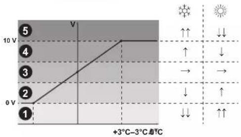
Below an example for cooling and heating operation is given.
- T_max is selected at 3^ .
- The target room temperature is 24°C.
11 About the system
| T ΔT V Capacity | level | Capacity request | ||
| 20°C -4°C 0 V | 1 | ↓↓ ↑↑ | ||
| 21°C -3°C 0 V | ||||
| 22.5°C -1.5°C 2.5 V | 2 | ↓ | ↑ | |
| 24°C 0°C 5 V | 3 | → | → | |
| 25.5°C 1.5°C 7.5 V | 4 | ↑ | ↓ | |
| 27°C 3°C 10 V | 5 | ↑↑ ↓↓ | ||
| 28°C 4°C 10 V | ||||
line
| Point | Temperature (V) | |---|---| | 1 | 0 | | 2 | 5 | | 3 | 7 | | 4 | 9 | | 5 | 10 |T Actual measured temperature
ΔT [Actual measured temperature]—[Target room temperature]
V Voltage output of controller (field supply).
Cooling capacity request
Heating capacity request
1\~5 Capacity level
↑↑ Cooling/heating capacity strongly increases
↑ Cooling/heating capacity increases
→ Unit keeps operating at same capacity level
↓ Cooling/heating capacity decreases
↓↓ Cooling/heating capacity strongly decreases
11.2.2 Y control: Operation with fixed Te/Tc temperature control
A fixed target evaporating temperature ( T_e ) / condensing temperature ( T_c ) can be set by the customer via the field settings of the control box: see 13(23)-14 and 13(23)-15 in "16.2 Field settings" [▶ 29]. This system does not require a specific external controller.
11.2.3 W control: Operation with 0-10 V DC capacity control
For W control, a controller (field supply) needs to be connected to the EKEA control box. The controller will generate a 0–10 V DC signal that will be used by the EKEA control box for the capacity control of the system.
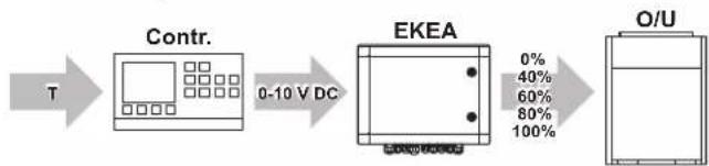
flowchart
graph LR
    A["T"] --> B["Contr."]
    B --> C["0-10 V DC"]
    C --> D["EKEA"]
    D --> E["O/U"]
Contr. Controller (field supply)
EKEA Control box
O/U Outdoor unit
0%\~100% Capacity control level sent to the outdoor unit via F1F2
0-10 V DC Voltage signal
T Temperature
The system needs a controller (field supply) with a temperature sensor. The temperature sensor can be used to control the following temperatures:
- Suction air temperature of the air handling unit
- Room air temperature
- Discharge air temperature of the air handling unit
The EKEA control box will interpret the 0–10 V DC signal according to 5 steps. The correlation between the voltage input and the system capacity is as follows:
| Step | Voltage input(a) | System capacity(b) | T_e during cooling operation | T_c during heating operation |
| 1 | 0.8 V 0% (OFF) — | — | ||
| 2 | 2.5 V | 40% | 13.5°C | 31°C |
| 3 | 5 V | 60% | 11°C 36°C | |
| 4 | 7.5 V | 80% 8.5°C | 41°C | |
| 5 | 9.2 V | 100% | 6°C | 46°C |
(a) Voltages shown are the centre points of each step range.
(b) The capacities mentioned in the table are not exact. The compressor frequency can vary and will have an impact on the system capacity.
- The system response to the 0–10 V DC output from the controller (field supply) is the same in cooling and heating operation. 10 V means 100% system capacity in cooling and heating operation. The controller will output a 0–10 V DC signal based on ΔT (for the definition of ΔT, see "11.2.1 X control: Operation with 0-10 V DC capacity control" [▶ 11]).
- In the table below an example is given.
- A T of 4^ in cooling operation means that the controller (field supply) needs to output 10 V, so that the cooling capacity will be 100%.
- A T of 4^ in heating operation means that the controller (field supply) needs to output 0V , so that the heating capacity will be 0% (OFF).
| Operation Target temperature | Actual measured temperature | T | Required system response |
| Cooling | 24°C | 28°C | +4°C High capacity (10 V) |
| Heating | 24°C | 28°C | +4°C No capacity (0 V) |
The response of the controller (field supply) must therefore be inverted for cooling or heating operation.
11.2.4 Z control: Suction air control
This control method corresponds with standard Daikin suction air control, as for normal VRV indoor units. The cooling/heating load is determined based on the difference between the suction air temperature and the setpoint.
The setpoint can be set in two different ways (see 11(21)-12 in "16.2 Field settings" [▶ 29]):
• Using a Daikin remote controller
- Using a 0-10 V DC voltage signal on C1C2, according to the table below:
| Output from controller [V] (field supply) | Output capacity level | T_set [°C] |
| <1.5 | Level 1 | 16 |
| 1.5≤x<3.5 | Level 2 | 20 |
| 3.5≤x<6.5 | Level 3 | 24 |
| 6.5≤x<8.5 | Level 4 | 28 |
| ≥8.5 | Level 5 | 32 |
11.2.5 Z' control: Discharge air control
Discharge air control is similar to suction air control, but the cooling/heating load is estimated by the difference between the discharge air temperature and the setpoint.
The setpoint can be set via field settings on the Daikin remote controller (see 14(24)-10 and 14(24)-11 in "16.2 Field settings" [▶ 29]).

INFORMATION
Changing the setpoint directly on the Daikin remote controller will not have effect on the discharge air temperature setpoint. The only way to change the setpoint for discharge air control, is using the field setting.
11.3 Operation signals
Input signals:
| Signal Description | |
| C1C2: 0-10 V DC voltage signal T | This signal has a different purpose based on the selected control type and the choice of the field settings. See the explanation of the control types and to the description of the field settings.This signal is used for X and W control, and it is optional for Z control. |
| T1T2: Operation ON/OFF Open: O | Operation OFF |
| Closed: Operation ON | |
| T3T4: Cooling/heating Open: Cool | ing |
| Closed: Heating | |
| T5T6:• R410A application: AHU fan malfunction• R32 application: Circulation airflow malfunction (unsafe scenario) | Open: Malfunction |
| Closed: No malfunction |
Output signals:
| Signal Description | |
| K1K2: Error status EKEA | Open: Error |
| Closed: No error | |
| K3K4: AHU fan instruction | Open: No fan instruction |
| Closed: Fan instruction | |
| K5K6: Compressor operation | Open: Compressor is not operating |
| Closed: Compressor is operating | |
| K7K8: Defrost operation | Open: Not in defrost or oil return operation |
| Closed: In defrost or oil return operation | |
| K9K10: R32 alarm | Open: No alarm |
| Closed: Alarm |
T1T2
The reaction of EKEA on the T1T2 input signal can be configured with field setting 12(22)-1 (see "16.2 Field settings" [▶29]).
T3T4
To use the T3T4 input signal:
- See 11(21)-13 in "16.2 Field settings" [▶ 29].
- See "16.1 To configure the control box" [▶ 27].
- When you want to use T3T4 on the EKEA master, this EKEA master must be set as the cooling/heating master first. See the user reference guide of the remote controller.
T5T6
In case of R410A applications or R32 applications where no safety measures are required, the T5T6 input can be short-circuited with a physical short-circuit bridge, in case the AHU is not predisposed to use this input.
Note: It is recommended to always use this input to inform the EKEA control box about AHU fan malfunctions. This increases the reliability of the entire system.
In case of R32 applications where safety measures are required, the following applies:
To send the T5T6 safety signal from the AHU controller to the EKEA control box, a normally open relay must be used.
The AHU controller must be programmed to send the T5T6 safety signal to the EKEA control box as follows:
- Conditions for which the T5T6 input must be opened:
- During a failure or a malfunction of the supply air fan.
- During a failure or a malfunction of the supply air or return air isolation dampers.
For the requirement of isolation dampers, see "11.7 Air handling unit" [▶ 14].
- When the supplied air flow rate is below the minimum required air flow rate while K3K4 is closed (there is a fan instruction by EKEA) and during steady operation.
To determine the minimum required air flow rate, see "12 Special requirements for R32 units" [▶ 17]. - During power failure of the AHU.
A normally open relay is used, so during power failure of the AHU, the T5T6 input of EKEA will automatically open.
- Conditions for which it is not required to open the T5T6 input, and it is recommended to keep it closed unless one of the above conditions is met:
- During maintenance or service.
- When the AHU is not operating.
When the AHU stops operating, the fans will be stopped and the dampers will be closed. Therefore, the T5T6 input signal can remain closed.
- During transient operation.
When the fans are starting, the airflow rate is allowed to be below the minimum required limit.
K3K4
There are several ways to configure the AHU fan instruction sent by EKEA. See 12(22)-3, 12(22)-6, 12(22)-11, 13(23)-2 in "16.2 Field settings" [▶ 29].

NOTICE
When the AHU fan instruction signal is activated, the air handling unit and fan must operate.
K9K10
To use the K9K10 output signal, see 15(25)-15 in "16.2 Field settings" [▶ 29].
11.4 Remote controller for EKEA
Compatible remote controller
BRC1H or newer.
11 About the system
When is a remote controller needed?
In general, for EKEA a remote controller does not need to be connected during normal operation. During configuration and servicing, it is required to connect a remote controller.
There are two exceptions for which a remote controller is needed during normal operation:
- In case of Z control, when the C1C2 signal is not used to set the setpoint.
- In case of EKEAs in remote controller group control (i.e. when multiple EKEAs are connected to one remote controller):
- Master-slave configuration (i.e. multiple EKEAs for a single air handling unit) interlaced heat exchanger
- Multiple air handling units with one EKEA per air handling unit
In cases where a remote controller is not required during normal operation, it may be decided to disconnect the remote controller. Keep the following items in mind:
- To disconnect the remote controller, follow the steps explained in "16.1 To configure the control box" [▶ 27].
- It is advised to use the following optional input signals in this situation:
• T1T2: To start or stop EKEA
- T3T4: To set cooling/heating (if EKEA is the cooling/heating master of the system)
Remote controller group control
Follow the instructions from the manual of the remote controller to use remote controller group control on EKEA. For normal indoor units, the unit number can be verified by checking fan operation visually. For EKEA, this can be done by checking the fan instruction signal K3K4.
11.5 Selection of the expansion valve kit
Use the following table to select the expansion valve based on the cooling and the heating capacity of the AHU heat exchanger:
| EKEXVA capacity class | Allowed heat exchanger capacity (kW) | |||
| Cooling(a) | Heating(b) | |||
| Min. Max. | Min. Max. | |||
| 50 5 6.2 | 5.6 7 | |||
| 63 6.3 7 | 8 7.1 8.8 | |||
| 80 7.9 9 | 9 8.9 | 11.1 | ||
| 100 10 | 12.3 | 11.2 | 13.8 | |
| 125 | 12.4 | 15.4 | 13.9 | 17.3 |
| 140 | 15.5 | 17.6 | 17.4 | 19.8 |
| 200 | 17.7 | 24.6 | 19.9 | 27.7 |
| 250 | 24.7 | 30.8 | 27.8 | 34.7 |
| 300 | 30.9 | 36.1 | 34.8 | 41.7 |
| 350 | 36.2 | 42.8 | 41.8 | 48.6 |
| 400 | 42.9 | 47.1 | 48.7 | 55 |
| 450 | 47.2 | 54.2 | 55.1 | 62 |
| 500 | 54.3 | 61.6 | 62.1 | 69.3 |
(a) Cooling:
• Saturated suction temperature (SST) = 6°C
• Air temperature = 27°C DB/19°C WB
• Superheat (SH) = 5 K
(b) Heating:
• Saturated suction temperature (SST) = 46°C
• Air temperature = 20°C DB
- Subcool (SC) = 3 K
NOTICE
- The expansion valve (electronic type) is controlled by the thermistors that are added in the refrigerant circuit. Each expansion valve can control a range of air handling unit sizes.
- Extraneous substances (including mineral oils or moisture) must be prevented from getting mixed into the system.
- SST: Saturated suction temperature at exit of air handling unit.
11.6 Outdoor unit
11.6.1 Possible outdoor units
| Outdoor unit | Layout | ||
| Pair | Multi Mix | ||
| ERQ (HP) | ● | — | — |
| VRV HP | ● | ● | ● |
| VRV HR | N/A | ●(a) | ● |
(a) • Only possible in case of Z and Z' control.
- VRV HR is not possible with master-slave configuration.
- Allowed
— Not allowed
N/A Not applicable
HP Heat pump
HR Heat recovery
11.6.2 ERQ outdoor units
The control box can only be connected to an ERQ outdoor unit in pair application. Only one expansion valve kit EKEXVA63\~250 can be used per control box and per air handling unit.
| ERQ | EKEXVA |
| 100 | 63~125 |
| 125 | 63~140 |
| 140 | 80~140 |
| 200 | 100~250 |
| 250 | 125~250 |
11.6.3 VRV outdoor units
The control box can be connected to some types of VRV outdoor units (see the Engineering Data Book for outdoor units that are in scope) with a maximum number of 3 connectable control boxes to one outdoor system. A single control box can only be combined with one expansion valve kit.
11.7 Air handling unit
NOTICE
- For R410A: The design pressure of the connected air handling unit MUST be minimum 4.0 MPa (40 bar).
- For R32: The design pressure of the connected air handling unit MUST be minimum 4.17 MPa (41.7 bar).
NOTICE
The connected air handling unit MUST comply with the requirements of the International Standard IEC 60335-2-40:2022.

NOTICE
EKEA and EKEXVA are only parts of an air handling unit system, complying with partial unit requirements of the International Standard IEC 60335-2-40:2022. As such, they must ONLY be connected to other units that have been confirmed as complying to corresponding partial unit requirements of this International Standard.
For installation of the air handling unit, see the air handling unit installation manual.
The connected air handling unit must be designed for R410A or R32 applications.
In case of R32 systems that require safety measures, take the following safety requirements into account:
- The air handling unit must be capable of supplying a minimum airflow rate ( Q_min ) for R32 safety. See "Figure 2" [▶3].
- Based on the conditioned space and the refrigerant amount, the air handling unit should make sure it operates only in the circulation airflow region (zone 1 in "Figure 2" [▶3]).
- The air handling unit must be equipped with supply and return air isolation dampers.
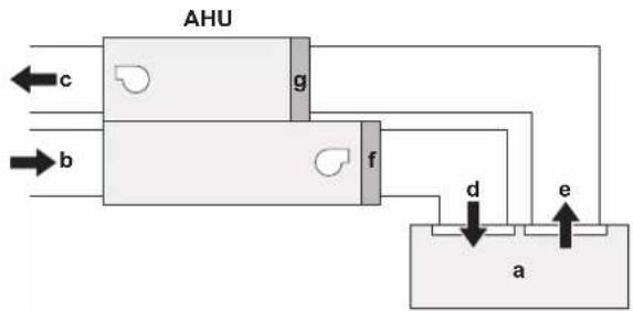
flowchart
graph TD
    A["Input"] --> B["AHU"]
    C["Input"] --> B
    D["b"] --> B
    E["c"] --> B
    F["g"] --> B
    G["f"] --> B
    H["d"] --> I["a"]
    J["e"] --> I
    B --> K["Output"]
AHU Air handling unit
a Conditioned space
b Outdoor air
c Exhaust air
d Supply air
e Extract air
f Supply damper
g Return damper
- The presence of dampers will allow to:
- Block the mixture of air and refrigerant going inside the building, in the case of a leak;
- Establish a safe situation even though the compressor of the VRV system would continue operating (e.g. defrost operation)
- The air handling unit should be able to output an additional error (R32 safety related), in case the airflow rate supplied by the air handling unit would drop below legal requirements. The air handling unit must be able to check the current airflow rate and compare it to the target airflow rate (Q_) . See T5T6 specifications in "11.3 Operation signals" [▶ 13].
- When the fans of the air handling unit are stopped, the supply and return isolation dampers need to close.
11.8 Connection ratio and heat exchanger volume limitations
Connection ratio and heat exchanger volume limitations for pair and multi applications
The connection ratio limit depends on the application.
For pair and multi applications, the lower limit of the connection ratio is 75% in general. However, if more strict requirements for the heat exchanger volume are satisfied, the lower limit of the connection ratio is 65%.
See the manual of the outdoor unit for more detailed information.
For ERQ, these connection ratio limitations are NOT applicable. Follow the combination table in "11.6.2 ERQ outdoor units" [▶ 14] instead.
Heat exchanger volume limitations
The limitations for the volume of the AHU heat exchanger are shown in the table below. In case of pair and multi applications, for connection ratios between 65% and 75%, more strict limitations are applicable.
For ERQ, follow the general limits.
| Capacity class | Minimum heat exchanger volume [dm3] | |
| General limits (65%≤CR<75%) | ||
| Only for pair and multi applications | ||
| 50 0.95 | 1.09 | |
| 63 1.02 | 1.18 | |
| 80 1.42 | 1.64 | |
| 100 | 1.51 1.74 | |
| 125 | 1.98 2.29 | |
| 140 | 2.54 2.94 | |
| 200 | 3.02 3.49 | |
| 250 | 3.97 4.58 | |
| 300 | 4.53 5.23 | |
| 350 | 5.48 6.32 | |
| 400 | 6.04 6.97 | |
| 450 | 6.99 8.07 | |
| 500 | 7.55 8.72 | |
CR Connection ratio
11.9 Master-slave configuration
In case of interlaced heat exchanger applications, a master-slave configuration of EKEA can be used to reduce the number of cables installed in the field. This is achieved by having a unique master control box, which has all the external inputs/outputs (I/O), and several slaves with a limited number of external I/O.
The master-slave function is activated via a field setting and can only be used with X, Y and W control (all connected EKEAs must be set to the same control type). Only one EKEA can be set as master, the rest of the connected EKEAs must be set to slaves (for more information see the field setting 14(24)-3 in "16.2 Field settings" [▶ 29]). The maximum number of EKEAs that can be connected together is limited to 10 (including the master EKEA).
The communication between the master and the slave EKEA control boxes is achieved in part via P1P2 and in part via additional physical wires. Therefore, to be able to use this functionality, a remote controller must always be connected (see "11.4 Remote controller for EKEA" [▶ 13]). The number of signals shared over the physical cable depends on the system layout.
There are two main system layouts in case of interlaced heat exchanger applications:
- Separate refrigerant circuits system
- Combined refrigerant circuit system
The figures below show examples of both systems. The systems that are shown in the examples each have three outdoor units, but this is just for illustrative purposes.
11 About the system
Example combined refrigerant circuit system:
flowchart
graph TD
    subgraph O/U_O/U
        A["TO I/U TO O/U TO multi Q2Q1 F2F1 F2F1"] --> B["EKEA Master"]
        C["TO I/U TO O/U TO multi Q2Q1 F2F1 F2F1"] --> D["EKEA Slave"]
        E["TO I/U TO O/U TO multi Q2Q1 F2F1 F2F1F"] --> F["EKEXVA"]
    end

    subgraph EKEA Master
        G["T2T1F2F1P2P1"] --> H["EKEA Slave"]
        I["T1F2F1P2P1"] --> J["EKEA Slave"]
    end

    subgraph EKEA Slave
        K["T2T1F2F1P2P1"] --> L["EKEA Slave"]
    end

    subgraph AHU_I/O
        M["R2T-R3T"] --> N["R2T-R3T"]
        O["R2T-R3T"] --> P["R2T-R3T"]
        Q["Contr."] --> R["EHU"]
    end

    B --> G
    B --> K
    B --> M
    B --> O
    B --> Q
    D --> M
    D --> N
    D --> P
    D --> Q
    style O/U_O/U fill:#f9f,stroke:#333
    style EKEA Master fill:#ccf,stroke:#333
    style EKEA Slave fill:#ccf,stroke:#333
    style AHU_I/O fill:#cfc,stroke:#333
AHU Air handling unit
AHU I/O Air handling unit input/output signals
BRC Remote controller
Contr. Controller (field supply)
EKEA Control box
EKEXVA Expansion valve kit
Master Master
O/U Outdoor unit
Slave Slave
TO I/U Interconnecting wiring to indoor units (and EKEAs)
TO multi Interconnecting wiring between the outdoor units in the same piping system
TO O/U Interconnecting wiring to other systems
Example separate refrigerant circuits system:
flowchart
graph TD
    subgraph Inputs
        direction TB
        A["O/U O/U O/U"] --> B["TO I/U TO O/U TO multi"]
        C["TO I/U TO O/U TO multi"] --> D["TO I/U TO O/U TO multi"]
        E["TO I/U TO O/U TO multi"] --> F["TO I/U TO O/U TO multi"]
        G["BRC P1 P2"] --> H["EKEA Master T2T1F2F1P2P1"]
        I["EKEA Slave T1F2F1P2P1"] --> J["EKEA Master T2T1F2F1P2P1"]
        K["EKEA Slave T2T1F2F1P2P1"] --> L["EKEA Master T2T1F2F1P2P1"]
    end

    subgraph Outputs
        M["AKU"] --> N["Contr."]
        O["EKEXVA"] --> P["EKEXVA"]
        Q["EKEXVA"] --> R["EKEXVA"]
        S["R2T-R3T"] --> T["R2T-R3T"]
        U["R2T-R3T"] --> V["R2T-R3T"]
    end

    style Inputs fill:#f9f,stroke:#333
    style Outputs fill:#ccf,stroke:#333
For the combined refrigerant circuit, there can be one or more outdoor units that are connected to the same refrigerant circuit.
For the separate refrigerant circuits, there is always more than one outdoor unit, so the number of outdoor units for this system is two or more.
Additionally, there may be other electrical connections in reality that are not shown in these examples. These are left out to make the figure more clear. See other parts of the manual to find out which electrical connections are required, and see the manual of the outdoor unit for more information about the system.
Note:
- The remote controller is used to share signals between the master and the slave EKEAs. To ensure proper functioning, the master EKEA must have the lowest unit number of the remote controller group. See the user reference guide of the remote controller for instructions on how to change the unit number.
- When you want to use T3T4 on the EKEA master, this EKEA master must be set as the cooling/heating master first. See:
- User reference guide of the remote controller
- "16.1 To configure the control box" [▶ 27]
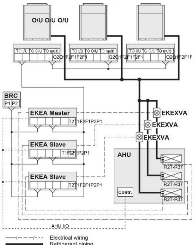
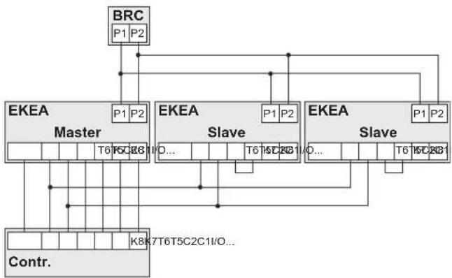
11.9.1 Combined refrigerant circuit system
The figure below shows how the inputs and outputs must be connected in case of a combined refrigerant circuit system. This means that the expansion valve kits of the EKEAs configured as master and slave, are connected to the same refrigerant circuit.
flowchart
graph TD
    A["BRC"] --> B["EKEA Master"]
    B --> C["T6 T5 C6 E6"]
    C --> D["Contr."]
    D --> E["K8 T7T6T5C2C1I/O..."]
    F["P1 P2"] --> B
    G["P1 P2"] --> H["EKEA Slave"]
    H --> I["T6 T5 C2B1"]
    I --> J["Contr."]
    J --> K["K8 T7T6T5C2C1I/O..."]
    L["P1 P2"] --> M["EKEA Slave"]
    M --> N["T6 T5 C2B1"]
    N --> O["Contr."]
    O --> P["K8 T7T6T5C2C1I/O..."]
    Q["P1 P2"] --> R["EKEA Slave"]
    R --> S["T6 T5 C2B1"]
BRC Remote controller
Contr. Controller (field supply)
EKEA Control box
I/O... Other input/output signals
Master Master
Slave Slave
Notes:
- The P1P2 connection between the remote controller, the EKEA master and the EKEA slaves is always required.
-
All other connections are optional depending on the situation:
-
In general, all inputs and outputs only need to be connected to the EKEA master.
- If C1C2 is used, it needs to be connected to the EKEA master and to all EKEA slaves.
- If T5T6 is used, it only needs to be connected to the EKEA master, the connection can be short-circuited on the EKEA slaves.
- If T5T6 is not used, the connection needs to be short-circuited on the EKEA master and on all EKEA slaves, see "11.3 Operation signals" [▶ 13].
- If K7K8 is used, it only needs to be connected to the EKEA master.
- There are other electrical connections to the EKEA control box that are not shown in the figure, these are left out for the clarity of the figure.
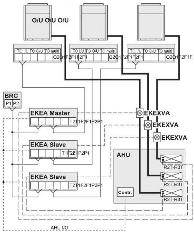
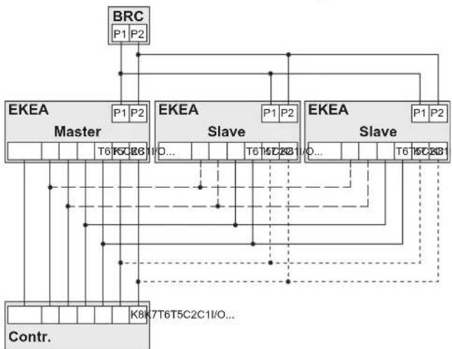
11.9.2 Separate refrigerant circuits system
The figure below shows how the inputs and outputs must be connected in case of a separate refrigerant circuit system. This means that the expansion valve kits of the EKEAs configured as master and slave, are connected to different refrigerant circuits.
flowchart
graph TD
    BRC["BRCC"] --> Master_EKEA["Master"]
    Master_EKEA --> T6["T6"]
    Master_EKEA --> K7T6["T5C2C1I/O..."]
    Master_EKEA --> Contr.
    Master_EKEA --> Slave_EKEA["Slave"]
    Slave_EKEA --> T6["T6"]
    Slave_EKEA --> K7T6["T5C2C1I/O..."]
    Slave_EKEA --> Contr.
    Slave_EKEA --> Comp
    Comp --> T6["T6"]
    Comp --> K7T6["T5C2C1I/O..."]
    Comp --> Contr.
    Master_EKEA --> P1["P1"]
    Master_EKEA --> P2["P2"]
    Slave_EKEA --> P1P2["P1"]
    Slave_EKEA --> P2P2["P2"]
    Comp --> P1P2
    Comp --> P2P2
    style Master_EKEA fill:#f9f,stroke:#333
    style Slave_EKEA fill:#ccf,stroke:#333
    style Comp fill:#cfc,stroke:#333
BRC Remote controller
Contr. Controller (field supply)
EKEA Control box
I/O... Other input/output signals
Master Master
Slave Slave
Notes:
- The P1P2 connection between the remote controller, the EKEA master and the EKEA slaves is always required.
-
All other connections are optional depending on the situation
-
In general, all inputs and outputs only need to be connected to the EKEA master.
- If C1C2 is used, it needs to be connected to the EKEA master and to all EKEA slaves.
- If T5T6 is used, it needs to be connected to the EKEA master and to all EKEA slaves.
- If T5T6 is not used, the connection needs to be short-circuited on the EKEA master and on all EKEA slaves, see "11.3 Operation signals" [▶ 13].
- If K7K8 is used, it needs to be connected to the EKEA master and to all EKEA slaves.
- There are other electrical connections to the EKEA control box that are not shown in the figure, these are left out for the clarity of the figure.
12 Special requirements for R32 units

INFORMATION
Also read the precautions and requirements in "2.1 Instructions for equipment using R32 refrigerant" [▶ 7].
For the safe operation of systems containing R32, make sure to meet the requirements as shown in the graphs and tables at the beginning of this manual:
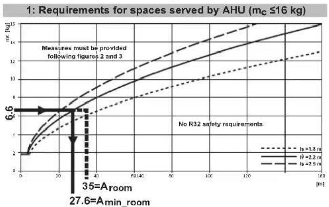
"Figure 1" [▶ 2]:
| English | Translation / description |
| 1: Requirements for spaces served by AHU (mc≤16 kg) | 1: Requirements for spaces served by air handling unit (mc≤16 kg) |
| Amin_room | Required minimum room area |
| but not less than | but not less than |
| hc | Release height, which is the vertical distance in metres from the floor to the point of release |
| LFL | Lower flammability limit = 0.307 kg/m3 for R32 |
| mc | Total refrigerant charge in the system |
| Measures must be provided following figures 2 and 3 | Measures must be provided following figures 2 and 3 |
| No R32 safety requirements | No R32 safety requirements |
| valid for mc>1.84 kg | valid for mc>1.84 kg |
"Figure 2" [▶ 3]:
| English | Translation / description |
| 2: Minimum circulation airflow | 2: Minimum circulation airflow |
| LFL | Lower flammability limit = 0.307 kg/m ^3 for R32 |
| m_c | Total refrigerant charge in the system |
| Q [m ^3 /h] | Circulation airflow rate |
| Q_min =60× m_e /LFL | Minimum circulation airflow rate |
| Zone 1: Q> Q_min | Zone 1: Q> Q_min |
12 Special requirements for R32 units
| English Translation | / description |
| Zone 2: Actions required Zone 2: | Actions required(IEC 60335-2-40:2022 Annex GG.9.2) |
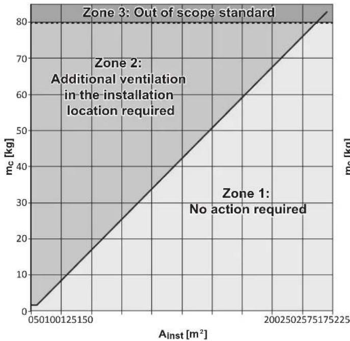
"Figure 3" [▶ 4]:
| English Translation | / description |
| 260LFL Absolute maximum for the | total refrigerant charge in the system |
| 50%LFL×H×(A _tot or A _inst )(valid for m _c >1.84 kg) | Maximum refrigerant charge to prevent mechanical extraction50%LFL×H×(A _tot or A _inst )(valid for m _c >1.84 kg) |
| A _inst | Installation space area |
| A _min | Minimum A _tot or A _inst (based on total refrigerant charge) to prevent mechanical extraction |
| A _tot | Total conditioned space areaA _tot is the sum of the floor areas of all the spaces connected by ducts to the air handling unit.Spaces where the airflow can be limited by zoning dampers, must NOT be included in the determination of A _tot . |
| H Height of the room = 2.2 m | |
| LFL Lower flammability limit = | 0.307 kg/m ^3 for R32 |
| m _c | Total refrigerant charge in the system |
| 3a: Requirements for AHU installation location(only applicable for indoor installations) | 3a: Requirements for air handling unit installation location(only applicable for indoor installations) |
| Zone 1: No action required Zone 1: No action required | |
| Zone 2: Additional ventilation in the installation location required | Zone 2: Additional ventilation in the installation location required |
| Zone 3: Out of scope standard Zone 3: Out of scope standard(IEC 60335-2-40:2022) | |
| 3b: Requirements for spaces served by AHU | 3b: Requirements for spaces served by air handling unit |
| Zone 1: Only circulation airflow required | Zone 1: Only circulation airflow required |
| Zone 2: Circulation airflow + Mechanical extraction | Zone 2: Circulation airflow + Mechanical extraction |
| Zone 3: Out of scope standard Zone 3: Out of scope standard(IEC 60335-2-40:2022) | |
12.1 Conditioned space requirements
If the system uses R32 refrigerant, extra safety measures might be required because R32 refrigerant is mildly flammable. This means that the system is restricted with respect to the total refrigerant charge and/or the floor area served.
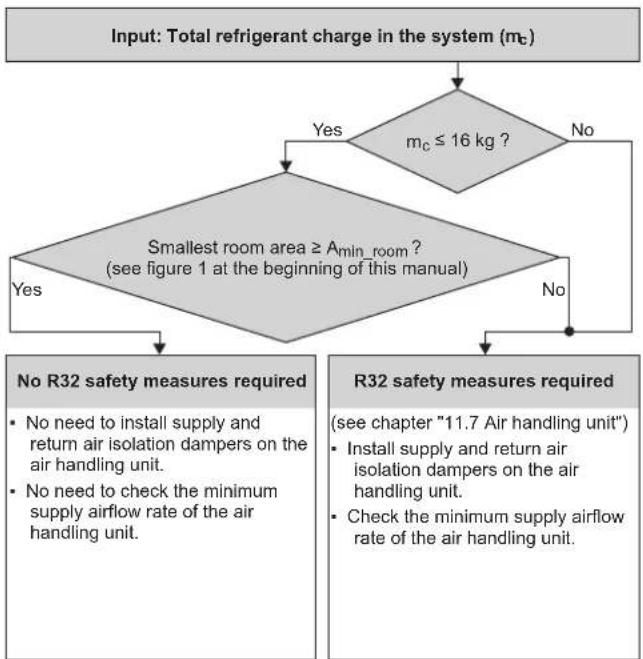
12.2 Determination of the safety requirements
Once the total refrigerant in the system has been determined, use the flowchart below to establish the R32 safety requirements:
flowchart
graph TD
    A["Input: Total refrigerant charge in the system (m_c)"] --> B{m_c ≤ 16 kg ?}
    B -->|Yes| C["Smallest room area ≥ A_min_room ? (see figure 1 at the beginning of this manual)"]
    B -->|No| D["No"]
    C --> E{Yes}
    C -->|No| F["No"]
    E --> G["No R32 safety measures required"]
    F --> H["R32 safety measures required"]
    G --> I["No need to install supply and return air isolation dampers on the air handling unit."]
    G --> J["No need to check the minimum supply airflow rate of the air handling unit."]
    H --> K["Install supply and return air isolation dampers on the air handling unit."]
    H --> L["Check the minimum supply airflow rate of the air handling unit."]
Note: In case the air handling unit is installed indoors, see figure 3a to determine if additional ventilation in the installation space is required.
12.2.1 Example 1
Installation of 6 HP R32 system:
• Total conditioned space area: 100 m²
- Smallest room area: 35 ~m^2
- Release height (h_0) : 2.2 m
• Total refrigerant charge: 6.6 kg
- Outdoor installation of air handling unit
line
| Distance (m) | I_s = 1.8 m | I_s = 2.2 m | I_s = 2.5 m | | ------------ | ----------- | ----------- | ----------- | | 0 | 0 | 0 | 0 | | 20 | ~4 | ~6 | ~8 | | 40 | ~6 | ~9 | ~11 | | 60 | ~8 | ~11 | ~13 | | 80 | ~10 | ~13 | ~14 | | 100 | ~11 | ~14 | ~15 | | 120 | ~12 | ~14.5 | ~15 | | 140 | ~13 | ~15 | ~15 | | 160 | ~14 | ~15 | ~15 |Based on figure 1, no R32 safety measures are required ( A_room > A_min_room ).
12.2.2 Example 2
Installation of 8 HP R32 system:
• Total conditioned space area: 140 m²
- Smallest room area: 50 ~m^2
- Release height (h_0) : 2.2 m
• Total refrigerant charge: 14.4 kg
- Outdoor installation of air handling unit
Based on the smallest room area, "Figure 1" [▶2] indicates to follow the requirements in figures 2 and 3.
3b: Requirements for spaces served by AHU
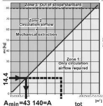
line
| tot [m²] | mJ [kJ] | | -------- | ------- | | 0 | 0 | | 12 | 14.4 | | 25 | 30 | | 57 | 60 | | 152 | 90 | | 255 | 120 | | 575 | 150 | | 1522 | 180 |2: Minimum circulation airflow
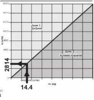
line
| Region | Value | |--------|-------| | Zone 1: DoQtime | 28.14 | | Zone 2: Actions required | 60.05 | | Label | 14.4 |- Based on figure 3b, only circulation airflow is required (A tot >A min ).
- Based on figure 2, the minimum circulation airflow needs to remain above 2814m^3/h .
Conclusion: As long as the supplied airflow rate is above the minimum legal requirement (2814 m³/h), no additional limitations apply to this VRV R32 system.
12.2.3 Example 3
Installation of 8 HP R32 system:
- Total conditioned space area: 140 ~m^2
- Smallest room area: 50 ~m^2
- Release height (h _p ): 2.2 m
- Total refrigerant charge: 14.4 kg
- Indoor installation of air handling unit in a space of 20m^2
Based on the smallest room area, "Figure 1" [▶2] indicates to follow the requirements in figures 2 and 3.
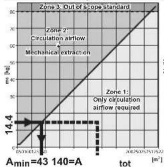
3b: Requirements for spaces served by AHU
line
Zone 3: Out of scope standard | Zone | Tot (m³) | Flow Rate (mL/kg) | |---|---|---| | Zone 1 | 0.5/10.0/1.75 | 14.4 | | Zone 2 | 0.5/10.0/1.75 | 14.4 | | Zone 3 | 300.2/50.75/51.25 | 80 | Amin=43 140=A2: Minimum circulation airflow
line
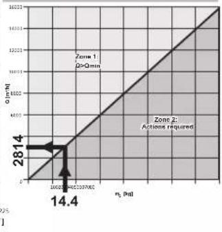
| n₂ (min) | Q (min) | | -------- | ------- | | 0 | 28.14 | | 10000 | 14.4 |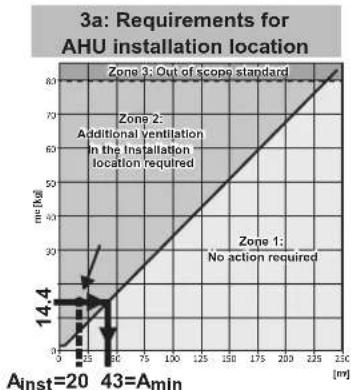
line
| Installation Distance (m) | Speed (km/h) | | ------------------------- | ------------ | | 0 | 0 | | 25 | 14.4 | | 50 | 20 | | 75 | 30 | | 100 | 40 | | 125 | 50 | | 150 | 60 | | 175 | 70 | | 200 | 80 | | 225 | 90 | | 250 | 100 | | 275 | 110 | | 300 | 120 |- Based on figure 3b, only circulation airflow is required (A tol >A min ).
- Based on figure 2, the minimum circulation airflow needs to remain above 2814m^3/h .
- Based on figure 3a, additional ventilation in the installation location is required ( A_inst < A_min ).
Note: Figure 3a is only applicable if the air handling unit is installed indoors.
Calculation of the minimum additional ventilation airflow rate ( Q_min ) in the installation location:
$$ Q _ {\min} = \frac {m _ {C} - m _ {\max}}{4 \times L F L} \times 2 \times 6 0 = 7 4 7 m ^ {3} / h $$
Where m_max is:
$$ m _ {\max} = 50 \% \times L F L \times H \times A _ {\text {inst}} = 50 \% \times 0.307 \times 2.2 \times 20 = 6.75 \text {kg} $$
Note: In case of additional ventilation, the lower edge of the openings extracting air from the room cannot be more than 100 mm above the floor.
13 Unit installation

WARNING
In case of R32 refrigerant, the installation MUST comply with the requirements that apply to this R32 equipment. For more information, see:
- "2.1 Instructions for equipment using R32 refrigerant" [▶7]
- "12 Special requirements for R32 units" [▶ 17]
For the control box and the expansion valve kit:
- The unit can be installed indoors and outdoors, but do NOT install it in direct sunlight. Direct sunlight will increase the temperature inside the unit and may reduce its lifetime and influence its operation.
- Choose a flat and strong mounting surface.
- The operating temperature of the unit is between -20^ and 52^ .
- Do NOT install the unit in or on the outdoor unit.
-
Do NOT install or operate the unit in rooms:
-
Where mineral oil, like cutting oil is present.
- Where the air contains high levels of salt, e.g. air near the ocean.
- Where sulphurous gas is present, e.g. in areas of hot springs.
- In vehicles or vessels.
- Where voltage fluctuates a lot, e.g. in factories.
- Where high concentration of vapor or spray are present.
- Where machines generating electromagnetic waves are present.
- Where acidic or alkaline vapor is present.
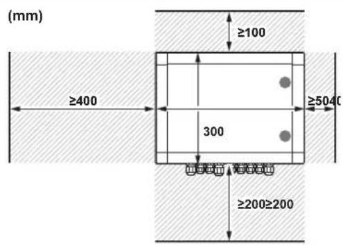
13.1 Control box
13.1.1 Installation site requirements of the control box

INFORMATION
The sound pressure level is less than 70 dBA.
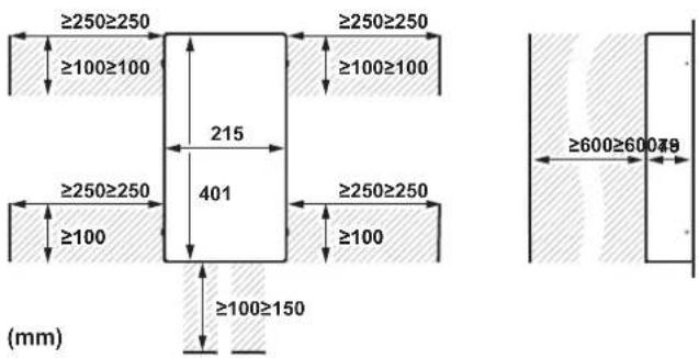
Mind the following spacing installation guidelines:
13 Unit installation
13.1.2 To install the control box
1 Open the cover with the key (delivered as accessory).
2 Attach the hanger brackets with their screws (delivered as accessory) to the control box.
3 Fix the control box with its hanger brackets to the mounting surface.
Use 4 screws (for holes of ∅6 mm).
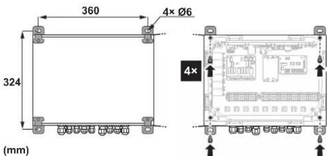
4 For electrical wiring: see "15.1.1 To connect the electrical wiring to the control box" [▶ 23].
5 Close and lock the cover after installation to ensure that the control box is watertight.
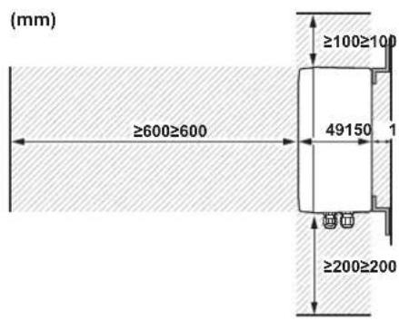
13.2 Expansion valve kit
13.2.1 Installation site requirements of the expansion valve kit
Mind the following spacing installation guidelines:
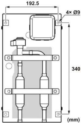
13.2.2 To install the expansion valve kit
1 Make sure that the expansion valve kit is installed vertically.
2 Remove the cover by unscrewing 4× M5.
3 Drill 4 holes on the correct position (measurements as indicated in figure below) and fix the expansion valve kit securely with 4 screws through the provided holes ∅9 mm.
13.3 Thermistors
13.3.1 Location of the thermistors
Different thermistors need to be installed depending on the control type. Follow the table below for this.
| Thermistor Control type | |||||
| X | Y | W | Z | Z' | |
| R1T: Suction air | — | — | — | ● | ● |
| R2T: Liquid pipe | ● | ● | ● | ● | ● |
| R3T: Gas pipe | ● | ● | ● | ● | ● |
| R4T: Discharge air | — | — | — | — | ● |
- Required
— Not required
Correct installation of the thermistors is required to ensure good operation.
| R1T | Thermistor (suction air)Install the thermistor either in the room that needs temperature control or in the suction area of the air handling unit.Note: For room temperature control the delivered thermistor (R1T) can be replaced by an optional remote sensor kit (see the technical engineering data). |
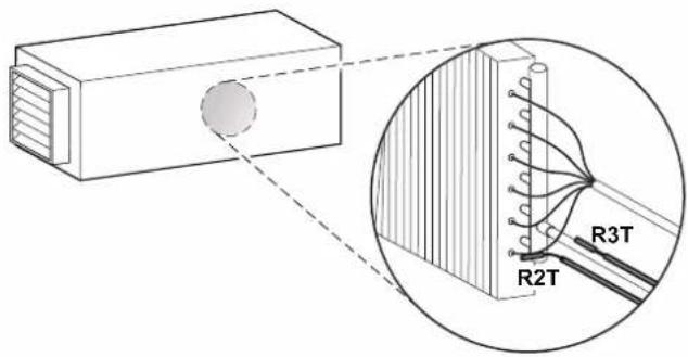
| R2T Thermistor (liquid pipe)Install the thermistor behind the distributor on the coldest pass of the heat exchanger (contact your heat exchanger dealer). |
| R3T Thermistor (gas pipe)Install the thermistor at the gas pipe of the heat exchanger as close as possible to the heat exchanger. |
| R4T Thermistor (discharge air)Install the thermistor in the discharge area of the air handling unit. |
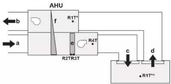
flowchart
graph TD
    A["Input a"] --> B["Input b"]
    B --> C["AHU"]
    C --> D["R1T*"]
    C --> E["R2TR3T"]
    C --> F["R4T"]
    C --> G["R1T*'"]
    H["Output c"] --> I["R1T*'"]
    J["Output d"] --> K["R1T*"]
AHU Air handling unit
*/** Location of R1T can be chosen.
a Outdoor air
b Exhaust air
c Supply air
d Extract air
e Heat exchanger
f Heat recovery
Evaluation must be done to check if the air handling unit is protected against freeze-up. This must be done during test operation.
The thermistor needs to be installed in an enclosed area. Install it inside the air handling unit, or shield it to prevent it from getting touched.
13.3.2 To install the thermistor cable
1 Put the thermistor cable in a separate protective tube.
2 Always add a pull-relief to the thermistor cable to avoid strain on the thermistor cable and loosening of the thermistor. Strain on the thermistor cable or loosening of the thermistor may result in bad contact and incorrect temperature measurement.
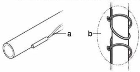
natural_image
Diagram showing a cable with labeled section 'a' and a magnified inset of a coiled wire (labeled 'b'), no text or symbols present.
NOTICE
- The connection must be made on an accessible location.
- To make the connection waterproof, the connection can also be made in a switch box or connector box.
- The thermistor cable must be located at least 50 mm away from power supply wire. Not following this guideline may result in malfunction due to electrical noise.
13.3.3 To install a longer thermistor cable
The thermistor is supplied with a standard cable of 2.5 m. This cable can be made longer up to 20 m.
1 Cut the wire or bundle the remainder of the thermistor cable. Keep at least 1 m of the original thermistor cable.
2 Strip the wire ±7 mm at both ends and insert these ends into the wire-to-wire splice.
3 Pinch the splice with the correct crimp tool (pliers).
4 After connection, heat up the shrink-insulation of the wire-to-wire splice with a shrink heater to make a watertight connection.
5 Wrap electrical insulation tape around the connection.
6 Put a pull-relief in front of and behind the connection.
13.3.4 To fix the thermistor
1 Make sure to install as follows:
- Put the thermistor wire slightly down to prevent water accumulation on top of the thermistor.
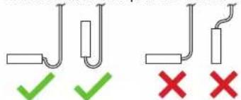
- Make good contact between thermistor and air handling unit. Put the top of the thermistors on the air handling unit, this is the most sensitive point of the thermistor.
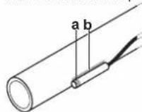
a Most sensitive point of the thermistor
b Maximise the contact
2 Fix the thermistor with insulating aluminum tape (field supply) to ensure a good heat transference.
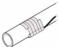
3 Put an insulation rubber (delivered as accessory) around the thermistor (R2T/R3T) to prevent loosening of the thermistor after some years.
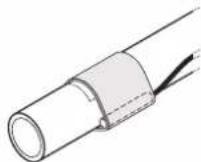
4 Fasten the thermistor with 2 cable ties (delivered as accessory).
14 Piping installation
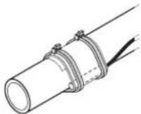
5 Insulate the thermistor with insulation tape (delivered as accessory).
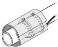
14 Piping installation

CAUTION
See "2 Specific installer safety instructions" [▶ 6] to make sure this installation complies with all safety regulations.
14.1 Preparing refrigerant piping
14.1.1 Refrigerant piping requirements

NOTICE
The piping and other pressure-containing parts shall be suitable for refrigerant. Use phosphoric acid deoxidised seamless copper for refrigerant piping.
- Foreign materials inside pipes (including oils for fabrication) must be ≤ 30 mg/10 m.
Refrigerant piping material
- Piping material: phosphoric acid deoxidised seamless copper
- Piping temper grade and thickness:
| Outer diameter (∅) | Temper grade Thickness (t) (a) | |
| 6.4 mm (1/4")9.5 mm (3/8")12.7 mm (1/2") | Annealed (O) ≥0.80 mm |  |
| 15.9 mm (5/8") Annealed (O) ≥0.99 mm | ||
| 19.1 mm (3/4")Half hard (1/2H) ≥0.80 mm22.2 mm (7/8") | ||
| 28.6 mm (1 1/8") Half hard (1/2H) ≥0.99 mm | ||
(6) Depending on the applicable legislation and the maximum working pressure of the unit (see "PS High" on the unit name plate), larger piping thickness might be required.
Refrigerant piping diameter
Make sure to install liquid pipe diameters in function of the expansion valve kit capacity class.
| EKEXVA | Liquid pipe (mm) | |
| R410A | R32 | |
| 50 | 6.4 | 6.4 |
| 63 | 9.5^(a) | 6.4 |
| 80 | 9.5^(a) | 6.4 |
| 100 | 9.5 | 9.5 |
| 125 | 9.5 | 9.5 |
| 140 | 9.5 | 9.5 |
| EKEXVA | Liquid pipe (mm) | |
| R410A | R32 | |
| 200 | 9.5 | 9.5 |
| 250 | 9.5 | 9.5 |
| 300 | 12.7 | 12.7 |
| 350 | 12.7 | 12.7 |
| 400 | 12.7 | 12.7 |
| 450 | 15.9^(b) | 12.7 |
| 500 | 15.9^(b) | 12.7 |
(a) Use transition pipe ID ∅9.5 mm (delivered as accessory).
(b) Use transition pipe ID ∅15.9 mm (delivered as accessory).
Refrigerant piping length and height difference
AHU
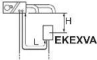
AHU Air handling unit EKEXVA Expansion valve kit
| Requirement | Limit | |
| H Max | Maximum height difference between AHU and EKEXVA | -5/+5 m (below or above the valve kit) |
| L | Maximum piping length between AHU and EKEXVAL is to be considered as a part of the total maximum piping length. See installation manual of the outdoor unit for piping installation. | 5 m |
14.1.2 Refrigerant piping insulation
- Use polyethylene foam as insulation material:
- with a heat transfer rate between 0.041 and 0.052 W/mK (0.035 and 0.045 kcal/mh°C)
- with a heat resistance of at least 120^
- Insulation thickness:
- Piping insulation must have a minimum thickness of 13 mm.
- Reinforce the insulation on the refrigerant piping according to the installation environment.
| Ambient temperature | Humidity | Minimum thickness |
| ≤30°C | 75% to 80% RH | 15 mm |
| >30°C | ≥80% RH | 20 mm |
14.2 Connecting the refrigerant piping

DANGER: RISK OF BURNING/SCALDING

WARNING
Only brazed connections are allowed.
14.2.1 To connect the refrigerant piping
For details, see manual of the outdoor unit.
1 Prepare the inlet/outlet field piping just in front of the connection (do NOT braze yet).
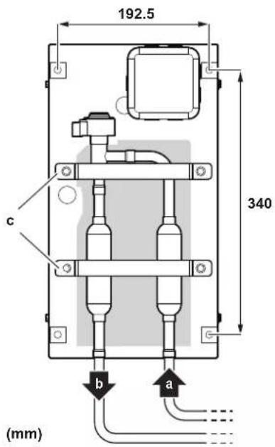
a Liquid piping from outdoor unit
b Liquid piping to air handling unit
c Pipe fixing clamps
2 Remove the pipe fixing clamps (c) by unscrewing 4× M5.
3 Remove the upper and lower pipe insulations.
4 Braze the field piping.

WARNING
- Make sure to cool the filters and valve body with a wet cloth and make sure the body temperature does not exceed 120°C during brazing.
- Make sure that the other parts such as electrical box, cable ties and wires are protected from direct brazing flames during brazing.
5 After brazing, put the lower pipe insulation back in place and close it with the upper insulation cover (after peeling off the liner).
6 Secure the pipe fixing clamps (c) in place again (4x M5).
7 Make sure that field pipes are fully insulated.
Field pipe insulation must reach up to the insulation you have put back in place in step 5. Make sure that there is no gap between both ends in order to avoid condensation dripping (finish the connection with tape).
14.2.2 To braze the pipe end
- When brazing, blow through with nitrogen to prevent creation of large quantities of oxidised film on the inside of the piping. This film adversely affects valves and compressors in the refrigerating system and prevents proper operation.
- Set the nitrogen pressure to 20 kPa (0.2 bar) (just enough so it can be felt on the skin) with a pressure-reducing valve.
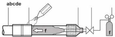
a Refrigerant piping
b Part to be brazed
c Taping
d Manual valve
e Pressure-reducing valve
f Nitrogen
- Do NOT use anti-oxidants when brazing pipe joints. Residue can clog pipes and break equipment.
- Do NOT use flux when brazing copper-to-copper refrigerant piping. Use phosphor copper brazing filler alloy (BCuP), which does NOT require flux.
Flux has an extremely harmful influence on refrigerant piping systems. For instance, if chlorine based flux is used, it will cause pipe corrosion or, in particular, if the flux contains fluorine, it will deteriorate the refrigerant oil. - ALWAYS protect the surrounding surfaces (e.g. insulation foam) from heat when brazing.
15 Electrical installation

CAUTION
See "2 Specific installer safety instructions" [▶ 6] to make sure this installation complies with all safety regulations.
15.1 Control box
15.1.1 To connect the electrical wiring to the control box

WARNING
Use only specified wires, and tightly connect wires to the terminals. Keep wiring in neat order so that it does not obstruct other equipment. Incomplete connections could result in overheating, and in worst case, electric shock or fire.

WARNING
The signals on the wires connected to the control box and the expansion valve kit are NOT safety extra-low voltages and are NOT safe to touch. The wires used for the connection of the control box and the expansion valve kit MUST therefore provide double insulation.

NOTICE
Thermistor cables and remote controller wires must be kept at least 50 mm away from power supply wires and from wires to the AHU controller. Not following this guideline may result in malfunction due to electrical noise.
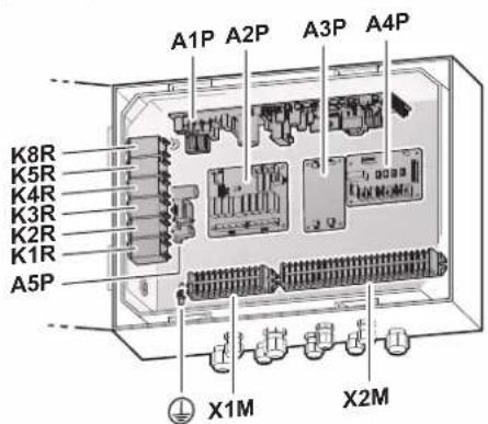
A1P PCB (main)
A2P PCB (relay)
A3P PCB (converter)
A4P PCB (demand)
A5P PCB (power supply)
K1R Magnetic relay (error state)
K2R Magnetic relay (fan ON/OFF)
K3R Magnetic relay (inverter operation)
K4R Magnetic relay (defrost)
K5R Magnetic relay (R32 alarm)
15 Electrical installation
K8R Magnetic relay (feedback connection relay PCB to main PCB)
X1M Terminal block
X2M Terminal block
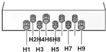
H1\~H9 Cable openings / cable glands. If not used, close with stoppers (delivered as accessory). H5 is used if the master-slave function is implemented. See "11.9 Master-slave configuration" [▶ 15].
1 For all used cable openings: install cable glands (with screw nuts and O-rings)(delivered as accessory).
2 For all unused cable openings: close the openings with stoppers (delivered as accessory).
3 Pull the cables inside the control box through their dedicated cable glands (as shown below: H1\~H9) and close the screw nut firmly in order to ensure good pull relief and water protection.
4 For all cables, provide an additional pull relief inside the control box. The figure below shows one example.
5 Connect the earth wire of the power supply to the sheet metal inside the EKEA as shown below to make sure that the earth connection is rigidly fixed.
Wire type Installation method
Single-core wire
Or
Stranded conductor wire twisted to "solid-like" connection
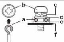
a Clockwise curled wire (single-core or twisted stranded conductor wire)
b Screw
c Spring washer
d Flat washer
e Coupling washer
f Sheet metal
6 Connect as shown in the following figure and table.
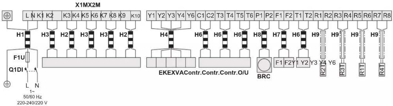
| F1U Recommended field fuse | 6 A | |
| MCA ^(a) | ||
| Q1DI | Earth leakage circuit breaker / residual current device | MUST comply with national wiring regulation |
| BRC | Remote controller | |
| Contr. | Controller (field supply) | |
| EKEXVA | Expansion valve kit | |
| O/U | Outdoor unit | |
(a) MCA=Minimum circuit ampacity. Stated values are maximum values.
| Terminal | Description | Connect to | Specifications | Cable(a) | ||
| Cores (+ entry) | Size (mm2)(b) | Max. length (m) | ||||
| L, N, earth | Power supply | 220-240 V / 220 V1~50/60 Hz | 3 core (H1) | 2.5 | — | |
| K1, K2 | Error status EKEA | Controller (field supply) | Digital output (voltage free)0-230 V ACMax. 0.5 A | 6 core (H3) | 0.75 | (c) |
| K5, K6 | Compressor operation | |||||
| K7, K8 | Defrost operation | |||||
| K3, K4 | AHU fan instruction | Controller (field supply) | Digital output (voltage free)0-230 V ACMax. 2 A. | 4 core (H2) | 0.75 | (c) |
| K9, K10 | R32 alarm | Digital output (voltage free)0-230 V ACMax. 0.5 A | ||||
| Y1~Y6 | Expansion valve kit | Digital output12 V DC | 5 core (H4) | 0.75 | 20 | |
| C1, C2 | 0-10 V DC voltage signal(d) | Controller (field supply) | Analogue input0-10 V DC | 8 core (H6) | 0.75 | 20(e) |
| T1, T2 | Operation ON/OFF | Digital input16 V DC | ||||
| T3, T4 | Cooling/heating | |||||
| T5, T6 | Malfunction(f) | |||||
| F1, F2 | Outdoor unit | Communication line16 V DC | 2 core (H7) | 0.75 | 100 | |
| P1, P2 | BRC Wired remote controller | Communication line16 V DC | 2 core (H8) | 0.75 | 100 | |
| R1, R2 | R2T Thermistor (liquid pipe) | Analogue input16 V DC | 8 core (H9) | 0.75 | 20 | |
| R3, R4 | R3T Thermistor (gas pipe) | |||||
| R5, R6 | R1T Thermistor (suction air) | |||||
| R7, R8 | R4T Thermistor (discharge air) | |||||
(a) Only use harmonised wire providing double insulation and suitable for the applicable voltage.
15 Electrical installation
(b) Recommended size (all wiring MUST comply with the applicable national wiring regulation).
(c) The maximum length depends on the connected external device (controller, relay, ...).
^(d) This signal has a different purpose based on the selected control type and the choice of the field settings. See the explanation of the control types and to the description of the field settings. This signal is used for X and W control, and it is optional for Z control.
(e) The same limit applies to the T5T6 total length in case of master-slave configuration.
^(f) • R410A application: AHU fan malfunction
• R32 application: Circulation airflow malfunction (unsafe scenario)
15.2 Expansion valve kit
15.2.1 To connect the electrical wiring to the expansion valve kit
1 Open the electrical box cover (a).
2 Push out ONLY the second lower wire intake opening (b) from inside to outside. Do NOT damage the membrane.
3 Pass the valve cable (with wires Y1\~Y6) from the control box through that membrane wire intake opening and connect the cable wires into the terminal connector (c) following instructions as described in step 4. Route the cable out of the valve kit box according to figure below and fix with cable ties.
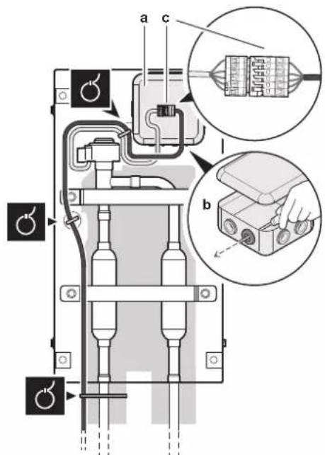
a Electrical box cover
b Second lower wire intake opening
c Terminal connector
4 Use a small screwdriver and follow indicated instructions for connecting cable wires into the terminal connector according to the wiring diagram.
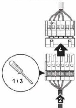
5 Make sure that field wiring and insulation is not squeezed when closing the valve kit box cover.
6 Close the valve kit box cover (4× M5).
16 Configuration
16.1 To configure the control box
Follow the steps below to configure EKEA. For the configuration of other parts of the system (example: outdoor unit, (BS/)SV unit, other indoor units, ... ; see the corresponding manuals). Do NOT start the operation of EKEA before the configuration steps have been completed. If EKEA is started while the configuration is not completed, the system could be damaged.
Start configuration

Connect the electrical wiring.
- Inputs and outputs are connected to the EKEA(s). This includes the T5T6 jumper, if needed. This jumper is only allowed for R410A applications (see "11.3 Operation signals").
- A remote controller is connected to the EKEA(s).
- Connect the power supply cable to the EKEA(s).
- Exceptions:
- In case of master-slave configuration, do NOT connect any inputs/outputs to the EKEAs yet.
- In case of group control (but not master-slave configuration):
- Do NOT connect C1C2 input in case it is used for Z control yet.
- Do NOT connect T3T4 and T1T2 wires yet.
- Do NOT connect the cables of the expansion valve yet. This should NOT be done before setting the capacity class, because it may damage the expansion valve body.
- Do NOT connect F1F2 transmission cables to the outdoor unit or (BS/)SV units yet. This can only be done after the capacity class is set.

Power ON the EKEA(s).

Set the EKEA(s) capacity class.
Only in case of master-slave applications this can be set with group setting (21-11). Otherwise, use 11-11.

Set the EKEA(s) control type.
In case of EKEAs in group control make sure that all the EKEAs are set to the same control type.
Group control = Multiple EKEAs are connected to one remote controller (R/C). 1 remote controller –to– many EKEAs pairing.
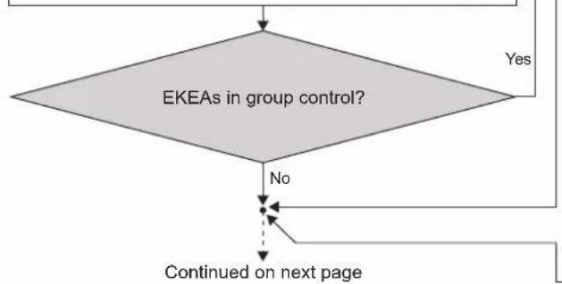
flowchart
graph TD
    A["EKEAs in group control?"] -->|No| B["Continued on next page"]
    A -->|Yes| C["End"]
Will master-slave configuration of EKEAs be used? No

Set the EKEA master and slaves.
- Fan instruction to Unit No. 0.
- Identify Unit No. 0 EKEA by checking K3K4 output.
- Set Unit No. 0 as master and other units as slaves (14(24)-3 setting).
- Connect all the inputs and outputs to and between EKEAs according to chapter "11.9 Master-slave configuration".

Identify Unit No. 0 EKEA.
- Fan instruction to Unit No. 0.
- Identify Unit No. 0 EKEA by checking K3K4 output.
- Connect C1C2 wire to Unit No. 0 EKEA (only in case C1C2 input is used with Z control).
- Connect T3T4 and T1T2 wire to Unit No.0 EKEA.
16 Configuration
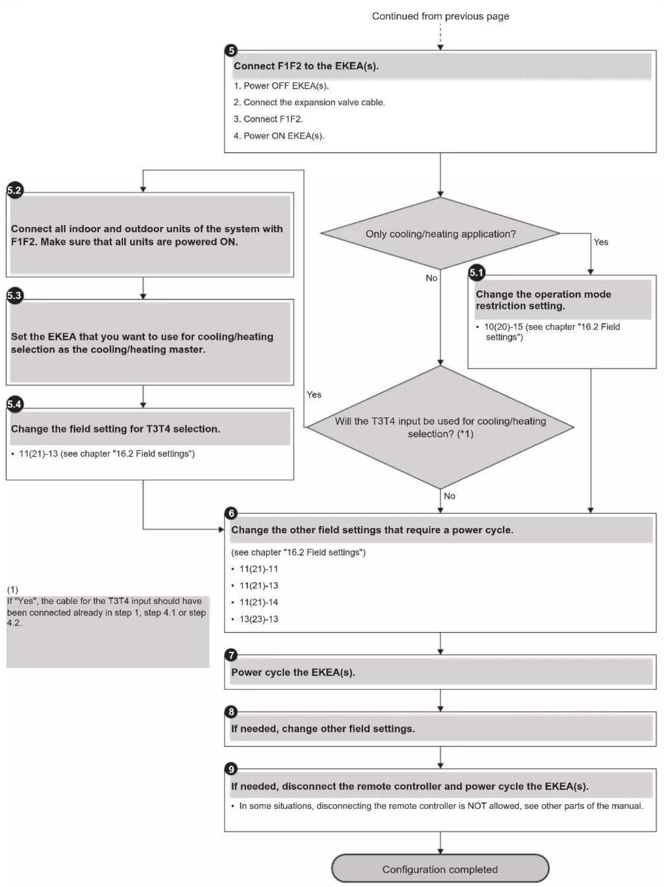
flowchart
graph TD
    A["Continued from previous page"] --> B["5 Connect F1F2 to the EKEA(s)."]
    B --> C{Only cooling/heating application?}
    C -->|Yes| D["Change the operation mode restriction setting."]
    C -->|No| E["6 Change the other field settings that require a power cycle."]
    D --> F["7 Power cycle the EKEA(s)."]
    F --> G["8 If needed, change other field settings."]
    G --> H["9 If needed, disconnect the remote controller and power cycle the EKEA(s)."]
    H --> I["Configuration completed"]

    subgraph Section 1
        B -->|5.2 Connect all indoor and outdoor units of the system with F1F2. Make sure that all units are powered ON.| B
    end

    subgraph Section 2
        C -->|5.3 Set the EKEA that you want to use for cooling/heating selection as the cooling/heating master.| C
    end

    subgraph Section 3
        D -->|Yes| E
        E -->|Yes| F
        E -->|No| G
    end

    subgraph Section 4
        F -->|11(21)-13 (see chapter "16.2 Field settings")| F
    end

    subgraph Section 5
        G -->|11(21)-11, 11(21)-13, 11(21)-14, 13(23)-13| G
    end

    subgraph Section 6
        H -->|1 (If "Yes", the cable for the T3T4 input should have been connected already in step 1, step 4.1 or step 4.2.)| H
    end
16.2 Field settings
| Setting Value (bold = default setting) | |
| 10(20)-2Control temperature selection for room air thermistor | 1 Use both the unit sensor (or remote sensor if installed) and the remote controller sensor. |
| 2 Use the suction air sensor only (or the remote sensor if installed). | |
| 3 Use remote controller sensor only. | |
| 10(20)-13Target superheat for X, Y and W control | 1 5°C |
| 2 10°C | |
| 3 15°C | |
| 10(20)-14Target subcool for X, Y and W control | 1 3°C |
| 2 5°C | |
| 3 10°C | |
| 10(20)-15Operation mode restriction(a) | 1 Cooling and heating |
| 2 Cooling only | |
| 3 Heating only | |
| 11(21)-9Target evaporating temperature (TeS) correction for W control | 1 0°C |
| 2 -1°C | |
| 3 -2°C | |
| 4 +1°C | |
| 11(21)-10Target condensing temperature (TcS) correction for W control | 1 0°C |
| 2 +1°C | |
| 3 +2°C | |
| 4 -1°C | |
| 11(21)-11Expansion valve kit capacity class(a) | 1 0 |
| 2 50 | |
| 3 63 | |
| 4 80 | |
| 5 100 | |
| 6 125 | |
| 7 140 | |
| 8 200 | |
| 9 250 | |
| 10 300 | |
| 11 350 | |
| 12 400 | |
| 13 450 | |
| 14 500 | |
| 11(21)-12Setpoint selection for Z control(b) | 1 Remote controller |
| 2 C1C2 input | |
| 11(21)-13Cooling/heating selection method(a)To change this setting, see "16.1 To configure the control box" [▶ 27]. | 1 Remote controller |
| 2 T3T4 input | |
| 11(21)-14Use of the centralised controller(a) | 1 Enabled |
| 2 Disabled | |
| 12(22)-1External operation ON/OFF input (T1T2 input) | 1 Forced OFF |
| 2 Operation ON/OFF | |
| 3 Protective device | |
| Setting Value (bold = default setting) | |
| 12(22)-2Thermostat differential changeover (if remote sensor is used) | 1 1°C |
| 2 0.5°C | |
| 12(22)-3Fan operation at thermostat off (heating) | 1 ON |
| 2 ON | |
| 3 OFF | |
| 12(22)-6Fan operation at thermostat off (cooling) | 1 ON |
| 2 ON | |
| 3 OFF | |
| 12(22)-11Hot start maximum duration time | 1 0 minutes |
| 2 3 minutes | |
| 3 5 minutes | |
| 4 10 minutes | |
| 13(23)-2Fan operation during defrost and oil return | 1 OFF |
| 2 ON | |
| 13(23)-13Temperature control type(a) | 1 X control |
| 2 Y control | |
| 3 W control | |
| 4 Z control | |
| 5 Z' control | |
| 13(23)-14Target evaporating temperature for Y control (cooling)(c) | 1 5°C |
| 2 6°C | |
| 3 7°C | |
| 4 8°C | |
| 5 9°C | |
| 6 10°C | |
| 7 11°C | |
| 8 12°C | |
| 13(23)-15Target condensing temperature for Y control (heating)(d) | 1 43°C |
| 2 44°C | |
| 3 45°C | |
| 4 46°C | |
| 5 47°C | |
| 6 48°C | |
| 7 49°C | |
| 14(24)-2Discharge air temperature correction factor | 1 0°C |
| 2 0.5°C | |
| 3 1°C | |
| 4 1.5°C | |
| 5 2°C | |
| 6 2.5°C | |
| 7 3°C | |
| 8 3.5°C | |
| 9 4°C | |
| 10 4.5°C | |
| 11 5°C | |
| 12 5.5°C | |
| 13 6°C | |
| 14 6.5°C | |
| 15 7°C | |
| 14(24)-3Master-slave function(e) | 1 Not active |
| 2 Master | |
| 3 Slave | |
17 Commissioning
| Setting Value (bold = default setting) | |
| 14(24)-10Cooling discharge air temperature setpoint | 1 13°C |
| 2 15°C | |
| 3 16°C | |
| 4 17°C | |
| 5 18°C | |
| 6 19°C | |
| 7 20°C | |
| 8 21°C | |
| 9 22°C | |
| 10 23°C | |
| 11 24°C | |
| 12 25°C | |
| 13 26°C | |
| 14 28°C | |
| 15 30°C | |
| 14(24)-11Heating discharge air temperature setpoint | 1 24°C |
| 2 26°C | |
| 3 27°C | |
| 4 28°C | |
| 5 29°C | |
| 6 30°C | |
| 7 31°C | |
| 8 32°C | |
| 9 33°C | |
| 10 35°C | |
| 11 37°C | |
| 12 39°C | |
| 13 41°C | |
| 14 43°C | |
| 15 45°C | |
| 15(25)-15External R32 safety output (K9K10 output) | 1 Disabled |
| 2 Enabled | |
(a) After changing this setting, a power cycle is required.
(b) When the C1C2 input is used during Z control, in the case of remote controller grouping, the indoor unit to which C1C2 is connected must have the lowest unit number.
^(c) Depending on the operating temperature condition or on selection of the air handling unit, operation or safety activation of the outdoor unit may take priority and actual T_s will be different from the set T_g .
^(d) Depending on the operating temperature condition or on selection of the air handling unit, operation or safety activation of the outdoor unit may take priority and actual T_c will be different from the set T_c .
(e) For the master-slave function, remote controller grouping is used. The master indoor unit needs to have the lowest unit number.
17 Commissioning
17.1 Checklist before commissioning
After installation and once the field settings are defined, the installer is obliged to verify correct operation by performing a test run. See the installation manual of the outdoor unit. Before executing "test run" as well as before operating the unit, you must check the following:
| Installation – Control boxCheck that the control box is properly installed to prevent abnormal noises and vibrations when starting up the unit. | |
| Installation – Expansion valve kitCheck that the expansion valve kit is properly installed to prevent abnormal noises and vibrations when starting up the unit. | |
| Installation – ThermistorsCheck that the thermistors are properly installed so that they do not come loose. | |
| Freeze-up preventionMake sure thermistor R2T (liquid pipe) is installed on the correct location to prevent freeze-up of the heat exchanger of the air handling unit. | |
| Field wiringCheck that the field wiring has been carried out according to the instructions described in the chapter "15 Electrical installation" [▶ 23], according to the wiring diagrams and according to the applicable national wiring regulation. | |
| Earth wiringBe sure that the earth wires have been connected properly and that the earth terminals are tightened. | |
| Pipe size and pipe insulationBe sure that correct pipe sizes are installed and that the insulation work is properly executed. |
17.2 To check during normal operation
When the test run was successful, an additional check needs to be carried out during normal operation.
1 Close the contact T1T2 (ON/OFF) or start operation with a remote controller.
2 Confirm functioning of the unit according to the manual and check if the air handling unit has collected ice (freeze-up).
If the unit collects ice: see "18.2 Symptom: The AHU heat exchanger is freezing up" [▶31].
3 Confirm that the fan of the air handling unit is ON.

NOTICE
- In case of poor distribution in the air handling unit, one or more passes of the air handling unit may freeze-up (collect ice). Put the thermistor (R2T) on this location.
- Depending on operation conditions (e.g. outdoor ambient temperature) it is possible that the settings must be changed after commissioning.
18 Troubleshooting
18.1 Solving problems based on error codes
If the unit runs into a problem, the user interface displays an error code. It is important to understand the problem and to take measures before resetting an error code. This should be done by a licensed installer or by your local dealer.
This chapter gives you an overview of most possible error codes and their descriptions as they appear on the user interface.

INFORMATION
See the service manual for:
- The complete list of error codes
- A more detailed troubleshooting guideline for each error
18.1.1 Error codes: Overview
| Code Description |
| A0 External protection device activated |
| A1 Malfunction of EKEA main PCB A1P |
| A9 Malfunction of electronic expansion valve |
| AJ Capacity setting error |
| C1 Failure of transmission (between indoor unit PCB and sub PCB) |
| C4 Malfunction of liquid pipe thermistor for heat exchanger |
| C5 Malfunction of gas pipe thermistor for heat exchanger |
| C9 Malfunction of suction air thermistor |
| CA Malfunction of discharge air thermistor |
| CJ Room temperature thermistor in remote controller abnormality |
| UJ-37 Airflow rate below the legal limit |
18.2 Symptom: The AHU heat exchanger is freezing up
- Check if the liquid thermistor (R2T) is put on the correct location. The thermistor must be put on the coldest location.
- Check if the thermistor has come loose. The thermistor must be fixed.
- The air handling unit fan is not operating continuously.
When the outdoor unit stops operating, the air handling unit fan must continue operation to melt the ice that was accumulated during outdoor unit operation.
Ensure that the air handling unit fan keeps operating.
For other issues, see the service manual.
19 Technical data
- A subset of the latest technical data is available on the regional Daikin website (publicly accessible).
- The full set of latest technical data is available on the Daikin Business Portal (authentication required).
19.1 Wiring diagram
The wiring diagram is delivered with the control box, located at the inside of the cover.
Legend
| Part Description |
| A1P PCB (main) |
| A2P PCB (relay) |
| A3P PCB (converter) |
| A4P PCB (demand) |
| A5P PCB (power supply) |
| F1U Field fuse |
| F1U (A1P) Fuse T 3.15 A 250 V |
| F1U (A2P) Fuse T 6.3 A 250 V |
| Part Description | |
| K1R Magnetic relay (error state) | |
| K2R Magnetic relay (fan ON/OFF) | |
| K3R Magnetic relay (inverter operation) | |
| K4R Magnetic relay (defrost) | |
| K5R Magnetic relay (R32 alarm) | |
| K8R Magnetic relay (feedback connection relay PCB to main PCB) | |
| Q1DI Earth leakage circuit breaker | |
| R1T Thermistor (suction air) | |
| R2T Thermistor (liquid) | |
| R3T Thermistor (gas) | |
| R4T Thermistor (discharge air) | |
| X1M | Terminal block |
| X2M | Terminal block |
| X3M | Terminal block |
| Y1E Electronic expansion valve | |
| Z*C | Noise filter (ferrite core) |
Notes
| 1 | Use copper conductors only. | |
| 2 | Colours: | |
| BLK | Black | |
| BLU Blue | ||
| BRN Brown | ||
| GRN | Green | |
| GRY | Grey | |
| ORG | Orange | |
| PNK | Pink | |
| RED Red | ||
| WHT | White | |
| YLW | Yellow | |
| 3 | Mandatory for R32 applications, short-circuited if not used for R410A applications. | |
| 4 | Symbols: | |
| L Live | ||
| N Neutral | ||
| →— | Connector | |
| ○ | Wire clamp | |
| ⊥ | Protective earth (screw) | |
| --- | Separate component | |
| == | Optional accessory | |
| ---- | Wiring depending on control type | |
| =■■■- | Field wiring | |
Position in switch box
| English | Translation |
| Position in switch box | Position in switch box |
Translation of text on wiring diagram
| English | Translation |
| 0-10 V DC input signal | 0-10 V DC input signal |
| 16 V DC digital input AHU error (NO) | 16 V DC digital input AHU error (normally open) |
| 16 V DC digital input cooling/heating (NC) | 16 V DC digital input cooling/heating (normally closed) |
| 16 V DC digital input ON/OFF (NO) | 16 V DC digital input ON/OFF (normally open) |
20 Glossary
| English Translation | |
| BRC wired remote controller BRC | wired remote controller |
| Only for X and W control(optional for Z control) | Only for X and W control(optional for Z control) |
| Only for Z and Z' control Only for Z | and Z' control |
| Only for Z' control Only for Z' control | |
| Outdoor Outdoor unit | |
| See note *** See note *** | |
| Voltage free contacts Voltage free | contacts |
20 Glossary
Dealer
Sales distributor for the product.
Authorised installer
Technical skilled person who is qualified to install the product.
User
Person who is owner of the product and/or operates the product.
Applicable legislation
All international, European, national and local directives, laws, regulations and/or codes that are relevant and applicable for a certain product or domain.
Service company
Qualified company which can perform or coordinate the required service to the product.
Installation manual
Instruction manual specified for a certain product or application, explaining how to install, configure and maintain it.
Operation manual
Instruction manual specified for a certain product or application, explaining how to operate it.
Maintenance instructions
Instruction manual specified for a certain product or application, which explains (if relevant) how to install, configure, operate and/or maintain the product or application.
Accessories
Labels, manuals, information sheets and equipment that are delivered with the product and that need to be installed according to the instructions in the accompanying documentation.
Optional equipment
Equipment made or approved by Daikin that can be combined with the product according to the instructions in the accompanying documentation.
Field supply
Equipment NOT made by Daikin that can be combined with the product according to the instructions in the accompanying documentation.


natural_image
Blank grid paper with no text, numbers, or symbols

natural_image
Blank grid paper with no text, numbers, or symbols