
CA-R-ISU.002AE - Uncategorized PIONEER - Free user manual and instructions
Find the device manual for free CA-R-ISU.002AE PIONEER in PDF.

| Product Type | Audio Interface Adapter |
| Brand | Pioneer |
| Model | CA-R-ISU.002AE |
| Compatibility | Pioneer car stereos with ISU port |
| Connection Type | Wired, male-to-female |
| Cable Length | Approximately 15 cm (6 in) |
| Weight | About 30 g (1 oz) |
| Material | Plastic housing, copper wiring |
| Input | ISU female connector |
| Output | ISU male connector |
| Power Requirement | Passive, no external power needed |
| Supported Audio Formats | Analog audio signals |
| Installation | Plug and play, no tools required |
| Operating Temperature | -20°C to 70°C (-4°F to 158°F) |
| Storage Temperature | -30°C to 80°C (-22°F to 176°F) |
| Maintenance | Clean with soft dry cloth; avoid liquids |
| Safety Precautions | Do not bend cables excessively; keep away from moisture |
| Spare Parts Availability | Contact Pioneer customer support |
| Warranty | 1 year limited warranty |
| Certifications | CE, RoHS |
Frequently Asked Questions - CA-R-ISU.002AE PIONEER
User questions about CA-R-ISU.002AE PIONEER
0 question about this device. Answer the ones you know or ask your own.
Ask a new question about this device
Download the instructions for your Uncategorized in PDF format for free! Find your manual CA-R-ISU.002AE - PIONEER and take your electronic device back in hand. On this page are published all the documents necessary for the use of your device. CA-R-ISU.002AE by PIONEER.
USER MANUAL CA-R-ISU.002AE PIONEER
1- Volume +
2- Volume -
3- Seek up
4- Seek Down
5- Source (Short press) /Mute (long press)
6- Accept incoming call
7- Voice
8- Reject incoming call
All installation work must be performed by a qualified professional installer only.
The manufacturer / dealer is not liable for any kind of incidental or indirect damages.
03/2021 ALL RIGHTS RESERVED. Technical changes possible. No liability for misprints.R0
Steering wheel control interface installation kit for:
ISUZU
Model: D-MAX
Year: 2020>
Kit content: SWC resistive interface wiring harness
radio adapter (*) if included
Customer code: CA-R-ISU.002AE
natural_image
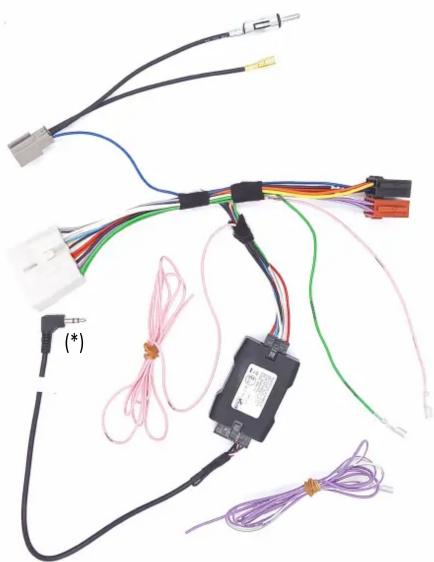
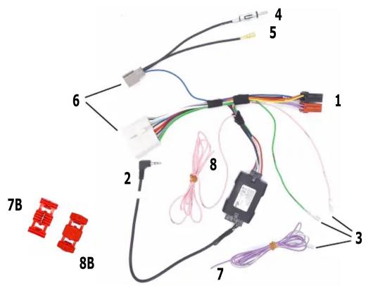
Electrical wiring diagram showing connections between components including wires, connectors, and a motor (no text or symbols visible)INSTALLATION MANUAL
All installation work must be performed by a qualified professional installer only.
The manufacturer / dealer is not liable for any kind of incidental or indirect damages.
03/2021 ALL RIGHTS RESERVED. Technical changes possible. No liability for misprints.
ATTENTION!
In order to prevent ESD damage, the WHEEL REMOTE JACK must be connected before plugging in the connectors on car side.
Connect cables to the radio side as follow:
1- to ISO CONNECTOR (red and black housings)
2- to WIRED REMOTE SOCKET (NOTE: do not connect to microphone socket)
3- to SERVICE (if required); function is marked on wire:
Green - Brake
Pink - Speed
Violet/White - Reverse
4- to FM/AM Radio Connector
5- to DAB Radio Connector
Connect cables to the car side as follow:
6- to CAR Connectors
7- to Red wire by using 8B (see next page)
8- to Violet wires by using 7B (see next page)
7.1
natural_image
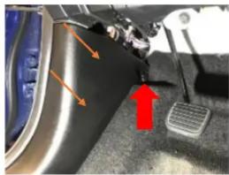
Close-up of a car's dashboard and steering wheel with orange arrows indicating motion (no text or symbols)7.1 Unscrew the screw indicated with the Red arrow and remove the plastic panel.
7.2
natural_image
Close-up of a car's engine compartment with visible wiring and a foot pedal (no text or symbols)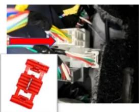
natural_image
Close-up of electrical wiring with multicolored wires and connectors (no visible text or symbols)7.2 By using the current-breaker (7B) connect the Red wire indicated by th Red arrow.
8.1
natural_image
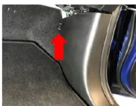
Close-up of a car's side panel showing a red arrow pointing to a specific area, no text or symbols visible.8.1 Unscrew the screw indicated with the Red arrow located near the passenger seat nd remove the plastic panel.
8.2
natural_image
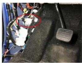
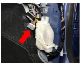
Close-up of a car's internal components with a red arrow pointing to a white plastic housing (no text or symbols visible)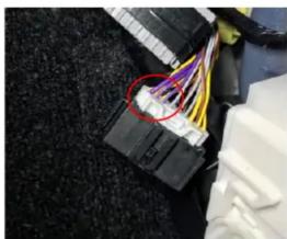
natural_image
Close-up of a black connector with colorful wires attached to its body, no visible text or symbols8.2 By using the current-breaker (8B) connect the Pink wire (8) with one of th 3 violet wires circled in Red in the picture above.