EPM-07-DIN - Uncategorized ENTES - Free user manual and instructions
Find the device manual for free EPM-07-DIN ENTES in PDF.


| Product Type | Network Analyzer |
| Model | EPM-07-DIN (EPM-07/EPM-07S) |
| Brand | ENTES |
| Operating Voltage (L-N) | 10-300 V AC |
| Operating Voltage (L-L) | 10-500 V AC |
| Frequency | 45-65 Hz |
| Auxiliary Supply Power | < 4 VA |
| Measuring Input Power | < 1 VA |
| Current Measuring Range (Direct) | 0.05 - 5.5 A |
| Current Measuring Range (with CT-25) | 2 - 120 A |
| Accuracy Class | 1% ± 1 digit |
| Current Transformer Ratio | 1 - 2000 (programmable) |
| Voltage Transformer Ratio | 0.1 - 4000.0 (programmable) |
| Demand Time | 1 - 60 minutes (programmable) |
| Serial Interface | MODBUS RTU (RS485) - EPM-07S only |
| Pulse Output | NPN transistor, max 50 mA, 5-24 V DC |
| Ambient Temperature | -5°C to +50°C |
| Display | Red LED, 4 digits |
| Weight | 0.54 kg (PR-19) / 0.50 kg (PK-26) |
| Protection Class | Class II, IP40 (front panel) |
| Mounting | Panel mount (PR-19) or DIN rail mount (PK-26) |
| Wire Cross-Section | 2.5 mm² |
| Fuse Recommendation | Type F, max 1 A |
| Cleaning | Dry cloth only, no solvents |
Frequently Asked Questions - EPM-07-DIN ENTES
User questions about EPM-07-DIN ENTES
0 question about this device. Answer the ones you know or ask your own.
Ask a new question about this device
Download the instructions for your Uncategorized in PDF format for free! Find your manual EPM-07-DIN - ENTES and take your electronic device back in hand. On this page are published all the documents necessary for the use of your device. EPM-07-DIN by ENTES.
USER MANUAL EPM-07-DIN ENTES
Operating Voltage (Un)
Operating frequency (1)
Auxiliary supply Power Consumption: < 4 VA
Measuring Input Power Consumption
V_in (True RMS)
In(True RMS)
Measuring Range
Class
Voltage Transformer Ratio (Vtr)
Current Transformer Ratio (Ctr)
Max. Ctr x Vtr
Demand Time
Serial Interface (for EPM-07S)
Baud Rate (for EPM-07S)
Address (for EPM-07S)
Parity (for EPM-07S)
Pulse Output
Switch Period
Operation Current
Operation Voltage
input
Ambient Temperature
Display
Dimensions
Equipment Protection Class
Box Protection Class
Box Material
Installation
Wire Crossection (for terminal)
Weight
Installation Category
Please look behind the device.
45-65 Hz
< 4 VA
<1VA
10-300 V AC 45-65 Hz. (L-N)
10-500 V AC 45-65 Hz. (L-L)
0.05 - 5.5 A-
2-120 A-(for CT-25)
10V...200 KV AC
0...215 M (W,V,N,VA)
99999999999.9 kWh, kVAch
1% ± 1 digit [(10%-110%) xFull Scale]
0.1 ... 4000,0
1,2000
40.000
1-60 min. (programmable)
MODBUS RTU (RS 485)
Optically Isolated, programmable
2400-38400 bps
1-247
No, Odd, Even, 8 Data bits, 2 Stop Bits
NPN Transistor
Min. 100 msec pulse period
Max. 50 mA
5...24 V DC, max. 30 VDC
12.48 V AC / DC
-5℃: +50℃
Red LED Display
PR-19, PK-26
Double Insulation-Class II (回)
IP 40 (front panel)
Non-flammable
Panel Mounted (PR-19)
Rail Mounted (PK-26)
2.5 mm²
0.54 kg (PR-19)
0.50 kg (PK-26)
Class III
Factory Settings
•
Trafo (Transformer) :
Ctr (Current Transformer Ratio) : 0001
lm (Turn number for CT-25 device) : 01
Utr (Voltage Transformer Ratio) : 0001.0
CAL (Calculation Method):
Pin : 0000 (Not Activated)
RS-485:
Adr (Address) : 1
E-1 (Energy Counter 1): on
E-2 (Energy Counter 2) : on
PULSE :
rAt 10 (Ratio) : 1
0-1 (Output 1): A+
o-2 (Output 2) : r-L
dEti (Demand Time): 15
Precautions For Installation and Safe Use
In CT-25 (120A) compliant models, only CT-25 current transformer must be used.
Other type of CT's have a high risk to damage to device
Failure to follow those instructions will result in death or serious injury.
- Disconnect all power before working on equipment. When the device is connected to the reberry, do so
- Do not try to clean the device with solvent or the like Only clean with dry cloth
- Verify correct terminal connections when wiring
- Electrical equipment should be serviced only by your component seller. - No responsibility is assumed by manufacturer or any of its subsidiaries for
- Only for rack panel mounting.
- Fuse must be F type and limit value doesn't exceed 1A.
No responsibility is assured by the manufacturer or any of its subsidiaries for any consequences arising out of the use of this material.
ENTES Elektronik Cihazlar İmalat ve Ticaret A.S.
Address: Dudullu OSB; 1. Cadde; No: 23 34775 Umraniya - ISTANBUL / TURKEY
Tel: +90 216 313 01 10 Fax: +90 216 314 16 15 www.entes.com.ir

NETWORK ANALYZER EPM-07 / EPM-07S
General
EPM-07/07S is a microprocessor based device which was developed for measuring the parameters in an electrical network. Measured parameters are displayed in 4 displays separately. EPM-07S has a MOOBUS serial communication interface.
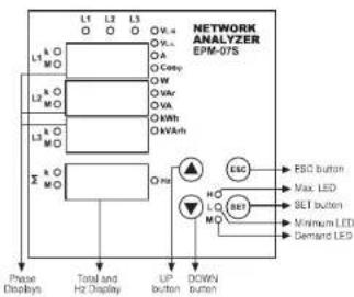
flowchart
graph TD
    A["Phase Displays"] --> B["Total and Hz Display"]
    B --> C["UP button"]
    C --> D["DOWN button"]
    D --> E["ESC"]
    E --> F["ESG button"]
    E --> G["Max LED"]
    E --> H["SEL button"]
    E --> I["Minimum LED"]
    E --> J["Demand LED"]
    A --> K[L1 L2 L3 L4 L5 L6 L7 L8 L9 L10 L11 L12 L13 L14 L15 L16 L17 L18 L19 L20 L21 L22 L23 L24 L25 L26 L27 L28 L29 L30 L31 L32 L33 L34 L35 L36 L37 L38 L39 L40 L41 L42 L43 L44 L45 L46 L47 L48 L49 L50 L51 L52 L53 L54 L55 L56 L57 L58 L59 L60 L61 L62 L63 L64 L65 L66 L67 L68 L69 L70 L71 L72 L73 L74 L75 L76 L77 L78 L79 L80 L81 L82 L83 L84 L85 L86 L87 L88 L89 L90 L91 L92 L93 L94 L95 L96 L97 L98 L99 L100
    style A fill:#f9f,stroke:#333
    style B fill:#ccf,stroke:#333
    style C fill:#cfc,stroke:#333
    style D fill:#fcc,stroke:#333
    style E fill:#ffc,stroke:#333
    style F fill:#fcc,stroke:#333
    style G fill:#fcc,stroke:#333
    style H fill:#fcc,stroke:#333
    style I fill:#fcc,stroke:#333
    style J fill:#fcc,stroke:#333

Using of EPM 07/07S:
Parameters (Vac, VU, A, W, VA, VA, Comp, KW), KVAm
) are monitored in L1, L2, L3 displays by pressing UP/DOWN buttons. Total Active (SW), Total Reactive Power (SVA), Total Apparent Power (SVA) and Frequency (Hz) values and average values of these parameters are monitored in 4th display.
Note: Vis or Vis should be selected for displaying the frequency value. Digital Inputs
EPM-07/07S has 2 digital inputs. Digital inputs have 2 functions. - When a remote device has activated, situation of this device which is connected to the digital input, can be monitored according to data register (Battery, thermostat, circuit breaker and motor position).
- When the digital inputs have activated in Energy Count menu, device will control the Energy Counters (Example: It is used for measuring of energy separately at the using of network and generator).
Energy Pulse Outputs
EPM-0707S has 2 Energy Pulse Outputs. These outputs give the pulses only for E-1 (Energy Counter).
Pull and Pull2: In "o-1 (Pulse1)", "o-2 (Pulse2)" menus which are in the pulse menu. Device give pulse according to selected energy parameters as [Active energy (ACI, A-I, A-E). Reactive energy (rEA, r-L, r-C)].
Please refer to the pulse menu for the coefficients of energies.
Monitoring Min. • Max. and Max. Demand Values:
Min. and Max. values are defined for VA, VA, A, W, VAR, VA, EW, EVAR, EVA. Demand values are defined for A, W, VAR, VA, EW, EVA, EVA. If measured instant value is smaller than min. value which was stored before, it is stored as new min. value. If measured instant value is greater than max. value which was stored before, it is stored as new max. value. Demand value is the average value of the measured values in demand time (15 minutes).
If one of defined parameters is displayed (i.e. "W") when demand button is pressed min., max or max. demand values are displayed. When an undefined parameter is displayed (i.e. "Casp") if demand button is pressed, instant value is continued to display.
H-L-M LEDs
HLM LEDs are dedicated to displaying the min., max. and max. demand values according to selected parameters.
H: Maximum Value, L: Minimum Value, M: Max. Demand Value
Calculation Methods for Active / Reactive Power Values
If the LED on the most right side blinks it represents that active power's / reactive power's direction is negative.
There are two methods for calculating total active and total reactive powers: 1) Active / Reactive power can be calculated by summing import and export values and displaying as a single value.
2) Active / Reactive power can be calculated according to direction as import / export.
1) The dot at the most right digit of the fourth display (During W is displayed) represents that displayed value is export active power value. Vice versa, displayed value is import active power value.
2) The dot at the most right digit of the fourth display (During EVAr is displayed) represents that displayed value is capacitive reactive power value. Vice versa, displayed value is inductive reactive power value. 3) The displayed parameter will not change if power is off after 30 seconds of stand by (io. 19).
at stand-by (to. W).
Measured Parameters:
| V1 (Phase Voltage) | Cov | Hr (Frequency) |
| V2 (Phase to Phase Voltage) | AI (MHz) (Import Active Energy) | Ir (Neutral Current) |
| A (Phase Current) | AE (MHz) (Export Active Energy) | 2.0V (Total Active Power) |
| B (Active Power) | f1(0.4V) (Import Reactive Energy) | 2.0V (Total Reactive Power) |
| Wt (Reactive Power) | g(0.4V) (Export Reactive Energy) | 2.0V (Total Apparent Power) |
| VA (Apparent Power) |
FUNCTIONS OF BUTTONS
In the monitoring mode, it is used to pass between (Vx. Vt., A. W. VAr, VA, Cosp. KWh, kVarh) parameters. At the programming mode, it provides to increase value of desired parameter and pass to the next menu.
In the monitoring mode, it is used to pass between (VLN, VLL, A, W, VAr, VA, Cosφ, kWh, kVath) parameters.
At the programming mode, it provides to decrease value of desired parameter and pass to the provides menu.
It is used for passing between the instant values such as. When it is pressed for 3 seconds, programming mode is entered. In the programming mode it is used for saving parameters and moving the sub menu.
In displaying mode, it is used for, passing the instant values which are displayed for min., max. and demand values in displaying mode, turn back to the previous menu turn back to the previous digit, when changing the numerical values and quitting the programming mode without saving.
If user password is activated and set button is pressed for 3 seconds, a pin code is required in order to enter to the menu. Current Transformer Ratio Setup
trR (This menu is not available in the devices which are adapted with CT-25.)
In this menu, current transformer ratio is set between 1 - 2000. Note: If the current transformer is not used between the system and EPM-07/07S, current transformer ratio is entered as '1'. Example: If a current transformer which has a ratio of 250/5A is used between the system and EPM-07/07S. Current transformer ratio is entered as '250/05A'.
SET Press SET button for 3 seconds (tA Fo menu is displayed)
Press SET button: trA Fo Otr menu is displayed (In CT-25 adapted devices, trA Fo pin is displayed instead.) (Note: trA Fo Utr menu can be displayed by scrolling the UP/DOWN buttons.)
trA Fo Ctr / trn / Utr Press SET button. Blinking the first digit of displayed value appears. (trA Fo Utr menu can be programmed similarly.)
Enter the blinking digit value by scrolling UP/DOWN buttons. Switch to the other digits by using SET button, use ESC button to go to previous digit. After you entered the last digit press SET button, "I'm ACh of" is displayed, "on" can be selected by scrolling UP/DOWN buttons. (Data is entered but is not activated yet. For activating the new data please follow the below steps).
Press ESC button one by one unit "SAU E SEI yES" is displayed.
Press SET button. When "SAU E SET yES" is displayed, if you press ESC button or choose "no" option instead of "yES" option by using UP-DCWN buttons, new data will be cancelled and previous value will be activated.
NETWORK ANALYZER
EPM-07 / EPM-07S

Programming the Turn Number:
This menu is available for CT-25 adapted devices. User enter the turn number, which is the number of how many tour the current cable has rounded into the CT-25. Numbers can be selected between 1-20. Greater the number of turn means greater the accuracy.

(二) 2017年1月1日
m 1 2 3 4 5 6 7 8 9 10 11 12 13 14 15 16 17 18 19 20 In min(A) 2.00 1.20 1.60 0.59 1.40 0.30 0.28 0.24 0.22 0.20 0.16 0.16 0.15 0.14 0.13 0.12 0.11 0.11 0.10 0.10 In max(A) 2.25 10.25 10.02 10.25 20.17 17.15 15.75 13.75 12.75 11.55 10.55 9.55 9.15 8.85 7.65 6.65 6.35 6.05
Voltage Transformer Ratio Setup
In this menu, voltage transformer ratio is set between
C P N 0.1 = 4000,0
Note: It's a volume of interest is not a net business the industry.
F0 Note: If the voltage transformer is not used between the system and EPM-07/07S, voltage transformer ratio is entered as '1'.
Example: I a voltage transformer which has a ratio of 34.5KW/100V
UCF is used between the system and EPM-
100 is earned as 345. (34500/100)
Reactive Energy Calculation Method Setting
5.21 Three different methods exist for reactive energy calculation in EPM-123P25. Final
The information about these methods are explained in below table.
Released values which must be entered in the menu are also indicated in the table
In order to select reactive power calculation method for mechanical and digital
energy/meters.
Nortical Expression Digital Expression Reactive Energy
Description
| Number of items | Each year episode | D | Evaluation method |
| 0 | 1 | rotation of voltage motor and multiply with current | It is the most preferred reactive power calculation method. |
| 2 | 3 | _ L A()V_ L A() | Total value of the multiple of V_ L and rises up to 10 harmonics. This calculation method is merely preferred for network analysis. |
| 4 | 5 | Power Triangle Methods According to this methodG = F/SPG: Reactive power, S: Apparent power, P: Active power |

Press SET button for 3 seconds (trA Fo menu is displayed)

Press SET button (tra Eq Or menu is displayed)


By using UP/DOWN buttons find "CAL/CL"
MENU

(1) 2023年1月1日


Press ESC button one by one until "SAU E SET YES" is displayed.

Press SET button. When "SAU E SET YES" is displayed, if you

press ESC button or choose "no" option instead of "YES" option

previous value will be activated.
Demand Time Setup:

In this menu, demand time is set between 1-60 minutes.

[Non-Text]

The Ground Truth image displays a single, solid horizontal line. According to Rule 2 (UNDERSCORE & LINE RULES), this is a stylistic or background line, not a placeholder underscore. Therefore, the OCR result must ignore it and output nothing or only meaningful text. The provided OCR content is "____", which consists of four underscores. This is an incorrect interpretation of the line as a placeholder, violating the rule that stylistic lines must be ignored. The OCR has hallucinated underscores where none should exist based on the GT's visual context. Hence, the OCR result is inconsistent with the Ground Truth.

By using UP-COWN buttons and "del b" menu.

2、本次发行的种类和面值

(2) Using an O-3VN database, the VISA is the 100% of a

Press SET button, "del" is displayed. (Data is ordered but is not
activated yet. For activating the new data please follow the below

[Non-Text]
Press ESC button one by one until (SALLE, SEL YES) is dispensed.

Press SET button. When "SALE SEL vES" is displayed, you press
ESC button or choose "no" option instead of "YES" option by using
UP-DOWN buttons, new data will be cancelled and previous value

ag and Erasing of minimum maximum and
monitoring an energy values

In this menu, values of min_max, or energy counters are erased.
I saves the instantaneously measured min. and max. values of SP14-07/025 into its memory. Please kindly look up to the virtual
- INPUTS into its memory. I have exactly look at the section - FUNCTIONS OF BUTTONS for min and max values
Note : Measured electrical parameters which are saved to the
memory are not affected from the electric interruptions.
in the 'RESET' menu when you quit from all menus, if you confirm
he changes.min, and max. values of all parameters or energy

ing the values of min. and max. or energy counter,

('RESE1 HL' menu is displayed)

rCS EE

By using UP-DOWN buttons, select
| -ES | E F | H I

(二)公司基本情况
-55|64|6-1

表一:本次发行的种类
PCJ CC C7

main to delete the parameter select
cES|EE|E-2

(1) 2017年

Press SET button ("YES ET" is displayed)

(一)公司董事会会议决议公告

(1) 2023 (4th ed. 6), the first (a = b - [25], a = b + 3).

press ESC button or choose "no" option instead of "yes" option

previous value will be actualized.
NETWORK ANALYZER
EPM-07 / EPM-07S
PK 26 Box Connection Diagram

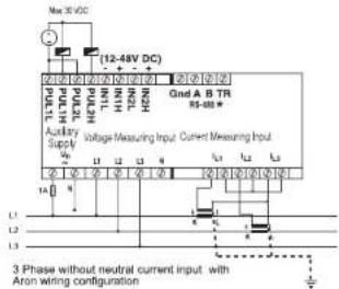
(Device needs an external neutral connection to be supplied)

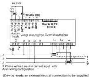
NETWORK ANALYZER EPM-07 / EPM-07S
PR 19 Box Connection Diagram
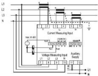
3 Phase neutral

3 Phase without neutral current input with Aron wiring configuration
(Device needs an external neutral connection to be supplied)
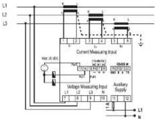
3 Phase without neutral
(Device needs an external neutral connection to be supplied)

flowchart
graph TD
    A["Current Measuring Input"] --> B["Bus 1"]
    A --> C["Bus 2"]
    A --> D["Bus 3"]
    A --> E["Bus 4"]
    A --> F["Bus 5"]
    G["Voltage Measuring Input"] --> H["L1"]
    G --> I["L2"]
    G --> J["L3"]
    G --> K["L4"]
    G --> L["L5"]
    M["Auditory Supply"] --> N["L1"]
    M --> O["L2"]
    M --> P["L3"]
    M --> Q["L4"]
    M --> R["L5"]
3 Phase without neutral current input with Aron wiring configuration
(Device needs an external neutral connection to be supplied)
\*Available only for EPM-07S
Note: For CT-25 models:
k: When CT-25 is used, Red cable is connected to k terminal l: When CT-25 is used, Black cable is connected to l terminal
B
NETWORK ANALYZER EPM-07 / EPM-07S
Pulse Menu
PUL In this menu, three parameters can be selected: "PUL SE nA; n": "PUL SE o-1", "PUL SE o-2".
PUL SE rAt 10 : Pulse ratio can be set as 1, 10, 100 (wh/VAm); 1, 16, 100 (kwh/kVAm); 2 MWh/MVAm.
PUL SE o-1: If this parameter is selected, in every increase in output 1, one pulse is counted. Output 1 parameter can be set as: A/D (Export/Import), A/-(Active Import), A/C (Active Export), r/LA (Inductive / Capacitive), r-L (Reactive Inductive), r-C (Reactive Capacitive). PUL SE o-2: If this parameter is selected, in every increase in output 2, one pulse is counted. Output 2 parameter can be set as: A/D (Export/Import), A/-(Active Import), A/C (Active Export), r/LA (Inductive / Capacitive), r-L (Reactive Inductive), r-C (Reactive Capacitive).
Press SET button for 3 seconds (tA For menu is displayed)

By using UP-DOWN buttons, find "PULSE" menu

Press SET button ("PUL SE rAt w" menu is displayed)

By using UP-OWN buttons, select "PUL SE o1" or "PUL SE o-2".

Press SET button

By using UP-DOWN buttons, select required parameter. PUL SE

Press SLT button

Press ESC button one by one until "SAU E SET YES" is displayed,
Press SET button. When "SAU E SET yES" is displayed, if you press ESC button or choose "no" option instead of "yES" option by using UP-DOWN buttons, now data will be cancelled and previous value will be activated.
Energy Counter (Eng Cnt) Menu
En9 EPM-07/075 has 2 energy counters: Energy counter 1 (E-1). Energy counter 2 (E-2). E-1/E-2' have 4 parameters:
LNC on Activate "E-1 / E-2" counters for energy counting without depending on any parameter.
E-1: Activate "E-1/E-2" counters, when digital input 1 is on (=1). E-2: Activate "E-1/E-2" counters, when digital input 2 is on (=1). E-2: "E-1" does not count when "E-2" is activated. (Only for "E-1" E-1: "E-2" does not count when "E-3" is activated. (Only for "E-2"
Note: Counting status is undefined if E-2 is selected on E-1 and if E-1 is selected on E-2. When the status is defined as above, both energy counters count while digital input is not on (-1) , but if either one or both digital inputs are on (-1) then counters will not count.
SET Press SET button for 3 seconds (14 Fo menu is displayed)
By using UP-DOWN buttons, find "Eng Cnt" menu
Press ESC button one by one until "SAU E SET yES" is displayed, Press SET button. When "SAU E SET yES" is displayed, if you press ESC button or choose "no" option instead of "yES" option by using UP-DOWN buttons, new data will be cancelled and previous value will be activated.

Password Setup: In this menu user password is defined and activated. You must define and activate a 4 digit user password for preventing device settings from the illegal usage. There are 2 sub menus under the "Pin" menu.
Changing of User Password:
P in This menu is used to change the user password. Note: Factory default value for user password is "0000"

change the user password, the monitoring mode

Press SET button for 3 seconds (trA-For menu is displayed)
Bu using UP-DOWN buttons, find "Pin" menu.
Press SET button ("Pin ACh IJA 1E" menu is displayed)

By using the UP-DOWN buttons, find "Pin CHA rgE" menu.

By using UP-DOWN-SET buttons, enter the old password

By using UP-DOWN-SET buttons, enter the new password

By using UP-DOWN-SET buttons, re-enter the new password.
Press SET button, "Pin CHA mgE" is displayed. (Data is entered but is not activated yet. For activating the new data please follow the below steps).
Press ESC button one by one until (SAUE SET YES) is displayed. P in CHA n9E
Press SET button. When "SAU E SET yES" is displayed, if you press ESC button or choose "no" option instead of "yes" option by using UP-DOWN buttons, new data will be cancelled and previous value will be activated.

ng the user password:

This menu is used for activating the user password. After the user password is activated, while the instant values are observed, user password is required in order to enter to the menu. If the wrong user password is entered, user can not enter to the menu.
Note: Factory default value of user password is "0000"

Press SET button for 3 seconds (t/A. For menu is displayed)
Bu using UP-DOWN buttons, find "Pin" menu

Press SET button ("Pin ACT IUA E" menu is displayed) P in ACE IUR EE

Press SET button. First digit of the displayed value is blining

Enter the blinking digit value by scrolling UP/DOWN buttons. Switch to the other digits by using SET button, use ESC button to go to previous digit. After you entered the last digit press SET button, "Pm ACL girl" is displayed, "on" can be selected by scrolling UP/DOWN buttons. (Data is entered but is not activated yet. For activating the new data please follow the below steps). Press ESC button one by one until "SAU.E. SET.vES" is displayed.
Press SET button. When "SAU E SET YES" is displayed, if you press ESC button or choose "no" option instead of "YES" option by using UP-DOWN buttons, new data will be cancelled and previous value will be activated.
NETWORK ANALYZER EPM-07 / EPM-07S
Serial Communication (Available only for EPM-07S)
LPM-07S has MODBUS RTU communication protocol which is optically polished. All measured parameters can be transferred to the
computer. Transformer ratios and communication parameters can be
set. Saved demand and energy values can be reset.
Parameter Settings
Address Parameters : Value can be enter between 001-247.
Baud Rate Parameters : Value can be selected as 2400, 480
19200 and 38400 bps.
Parity Parameters: "no", "odd" and "EUEn" can be selected

Press SET button for 3 seconds (tra Fio menu is displayed)

1-5-485

Press SET button ("Adr ESS" menu is displayed)


Enter the value of related parameters by scrolling UP/DOWN
buttons (001...247 / 2400 ...38400 / no. EUEn odd)
Press SET button. Adr ESS / pAU d / PAnly is displayed. (Data is
entered but is not activated yet. For activating the new data please
below the below alopa).
Press ESC button one by one until "SAU E SET YES" is displayed.
Press SET button. When "SAU E SET YES" is displayed, if you create ESC button or choose "no" option instead of "YES" option
by using UP-DOWN buttons, now data will be cancelled and
previous value will be activated.
MODBUS RTU PROTOCOL (Available only for EPM-075)
Standart MODEUS RTU message is shown below
| T | ADDRESS8 BIT | FUNCTION8 BIT | DATA100BIT | CROH | CROL | T |
The T times corresponds to a time in which data must not be exchanged on the communication bus to allow the connected devices to recognize the end of one message and the beginning of another. This time must be at least 3.5 characters at the selected baud rate. Address range (1-247) is address of the connected device. The data field contains data sent to the slave by master or data sent to master by slave.
CRC is a error check method by using MODBUS RTU protocol and consists of 2 bytes.
Available Modbus Function:
| 05H | HEAD HOLD REGISTERS |
| 06H | PRESET SINGLE REGISTER |
| 10H | PRESET MULTIPLE REGISTERS |
Read Hold (03) function is used for reading measured values and set value. If any request of reading of a register, excepted mentioned in register table, device will send an error message. For example to read phase 1 voltage by sending a message to the device,
01 03 00 00 00 02 XX XX
Of Device address
03 Function
CC MSB address
CD Receiver number/USB
02 Register number 188
XX CRC MSB
XX CRC LSB
Preset Single Register (06) function is used for writing the setting values, erasing the energy counter or resetting the min., max., demand values. Current transformers ratio can be set 0-2000 voltage transformer ratio can be set 1-40000, Min., Max., and Demand values can be only clear. If sent value is outside of this range device responds with an error message. Example. Setting CT as 100.
01 06 80 02 00 64 XX XX
0! Device address
061UNCOR 80 MSF ydd
02 LSB address
00 Data MSU
04 Data LS3
XX CRC MSU
XX CRC LSB
Preset Multiple Register(10H) is used to set more than one register at same
Time Example: Earnings CY as 160 (P=28.9)
Example. Setting CT as 100, CT as 20.0; 01.10.80/20.00/22.04.00/25.00/44.XX.OY
01 Device Address
10 Function
80 MSB address
00 LSEI address
00 Register number MSB
c2. Register Number LS8 01. 547-00-01
04 Byte touch 00 Data MSB
C# Data LSB
00 Data MSB
54 Data LSB
XX CRC MSB
XX CRC LSB
Digital Inputs (Available only for EPM-07S)
Digital input are sent in 16 bit hexadecimal format as below
55H 15 1 1 0 input 1
U U U D U U U U U U U U U D N2 D N1
MSB LSB
(see: Signatex Bps)
If 12-48 V AC / DC is applied to in1 (input 1), 0 (zero) bit of DIN register
Is set as "1". Otherwise, 0 (zero) bit is set as "0".
If 19-48 V AC / DC is applied to In2 (input 2). 1st bit of DIN register is set as "5". Otherwise, 1st bit is set as "3".
The Parameters are sent in 32bit Hexadecimal format. For example, 230.0V voltage will be sent as 00008@CH. Core values shall be divided
In 1,000.
0.980 Close will be sent as 0000304H. Energy values are sent in 64
bytes. 1254567890123456789 Wb = Alt, sd, AP, SC, up, 15, 114, 122, Wb
1234.067 00:1234.067 00 Wt = Rs 14 Rs 00, 00% SF 18 GE Wt
Specifications for data cable
- 24 AWG or thichur
- Less than 100 ohmy km
- Nominal characteristic impedance at 100 kJ/g or 100 mPa
- Less than 120 pF/m mutual pair capacitance (between two wires in a plan) - Less than 120 pF/m mutual pair capacitance (the capacitance between
one wire and all others connected to earth).
- Twisted Pair
ERROR CODES (Available only for EPM-07S)
Slave device (LPM-07S) sends error message when receive any missing query.
Error codes are given below
01 Invalid Function: If any message except given above is used, then 01 error
mentouges wil De San-
of invalid Register: Enter by will be send when a reading of a register is requested, except the registers which mentioned in table
03 Invalid data: If any different value is been set for dedicated Transformer values.
and nonzero for demand value, then error message 03 will be sent.
NETWORK ANALYZER EPM-07 / EPM-07S
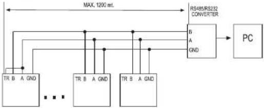
EPM-07S COMPUTER CONNECTION
31 DEVICES CAN BE CONNECTED AT THE SAME LINE
flowchart
graph TD
    A["TR B A GND"] --> C["AND"]
    B["TR B A GND"] --> C
    D["TR B A GND"] --> C
    E["TR B A GND"] --> C
    F["TR B A GND"] --> C
    C --> G["AND"]
    H["R5485/RS322 CONVERTER"] --> I["PC"]
    style A fill:#f9f,stroke:#333
    style B fill:#f9f,stroke:#333
    style C fill:#ccf,stroke:#333
    style D fill:#f9f,stroke:#333
    style E fill:#f9f,stroke:#333
    style F fill:#f9f,stroke:#333
    style G fill:#ccf,stroke:#333
EPM-07S-31
EPM-07S-2
EPM-07S-1
MAX. 247 DEVICES CAN BE CONNECTED AT SAME LINE BY USING REPEATER.

flowchart
graph TD
    A["RES A GND"] --> B["Max. 1200 mL"]
    B --> C["RS485/RS232 CONVERTER"]
    C --> D["PC"]
    style A fill:#f9f,stroke:#333
    style B fill:#ccf,stroke:#333
    style C fill:#cfc,stroke:#333
    style D fill:#fcc,stroke:#333
EPN-075-247
REPEATER
EPM075-31
EPM-07S-2
75-1
[Non-Text]
Dimensions
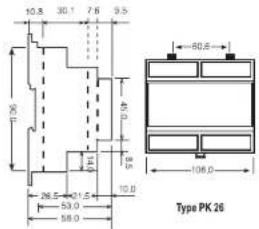

Type PR 19

NETWORK ANALYZER
EPM-07S
MODBUS REGISTER MAP
MODBUS REGISTER MAP
| ADDRESS | ADDRESS (HEX) | REGISTER | RW | RANGE | UNIT | MULTIPLIER | FORMAT |
| 6 | 0000 | L1 PHASE VOLTAGE | R | (0-3000xUT) | Volt | 0.1 | unsigned int |
| 2 | 0002 | L2 PHASE VOLTAGE | R | (0-3000xUT) | Volt | 0.1 | unsigned int |
| 4 | 0005 | L3 PHASE VOLTAGE | R | (0-3000xUT) | Volt | 0.1 | unsigned int |
| 6 | 0008 | L1 PHASE CURRENT | R | (0-6000xCT) | Amper | 0.001 | unsigned int |
| 8 | 0008 | L2 PHASE CURRENT | R | (0-6000xCT) | Amper | 0.001 | unsigned int |
| 10 | 0024 | L3 PHASE CURRENT | R | (0-6000xCT) | Amper | 0.001 | unsigned int |
| 12 | 0050 | L4 PHASE CURRENT | R | (0-6000xCT) | Amper | 0.001 | unsigned int |
| 14 | 0056 | L1-L2 PHASE-PHASE VOLTAGE | R | (0-3000xUT) | Volt | 0.1 | unsigned int |
| 16 | 0010 | L2-L3 PHASE-PHASE VOLTAGE | R | (0-3000xUT) | Volt | 0.1 | unsigned int |
| 18 | 0012 | L3-L4 PHASE-PHASE VOLTAGE | R | (0-3000xUT) | Volt | 0.1 | unsigned int |
| 30 | 0014 | L1 PHASE ACTIVE POWER | R | (-18000 - 18000xCTxT) | Wall | 0.1 | int |
| 22 | 0018 | L2 PHASE ACTIVE POWER | R | (-18000 - 18000xCTxT) | Wall | 0.1 | int |
| 24 | 0018 | L3 PHASE ACTIVE POWER | R | (-18000 - 18000xCTxT) | Wall | 0.1 | int |
| 26 | 0014 | L1 PHASE REACTIVE POWER | R | (-18000 - 18000xCTxT) | Var | 0.1 | int |
| 28 | 0010 | L2 PHASE REACTIVE POWER | R | (-18000 - 18000xCTxT) | Var | 0.1 | int |
| 30 | 0016 | L3 PHASE REACTIVE POWER | R | (-18000 - 18000xCTxT) | Var | 0.1 | int |
| 32 | 0020 | L1 PHASE APPEARNT POWER | R | (0 -18000xCTxT) | VA | 0.1 | unsigned int |
| 34 | 0027 | L2 PHASE APPEARNT POWER | R | (0 -18000xCTxT) | VA | 0.1 | unsigned int |
| 36 | 0024 | L3 PHASE APPEARNT POWER | R | (0 -18000xCTxT) | VA | 0.1 | unsigned int |
| 38 | 0026 | L1 PHASE CO2p | R | (1000 - 1000) | - | 0.001 | int |
| 40 | 0028 | L2 PHASE CO2p | R | (1000 - 1000) | - | 0.001 | int |
| 42 | 0024 | L3 PHASE CO2p | R | (1000 - 1000) | - | 0.001 | int |
| 44 | 0020 | TOTAL IMPORT ACTIVE POWER | R | (0 -54000xCTxT) | Wall | 0.1 | int |
| 46 | 0026 | TOTAL EXPORT ACTIVE POWER | R | (0 -54000xCTxT) | Wall | 0.1 | int |
| 48 | 0032 | TOTAL INDUCTIVE REACTIVE POWER | R | (0 -54000xCTxT) | Var | 0.1 | int |
| 50 | 0032 | TOTAL INDUCTIVE REACTIVE POWER | R | (0 -54000xCTxT) | Var | 0.1 | int |
| 52 | 0036 | TOTAL APPEARNT POWER | R | (0 -54000xCTxT) | VA | 0.1 | unsigned int |
| 54 | 0038 | AVERAGE INDUCTIVE CO2p | R | (1000 - 1000) | - | 0.001 | int |
| 56 | 0038 | AVERAGE CAPACITIVE CO2p | R | (1000 - 1000) | - | 0.001 | int |
| 58 | 0034 | IT RELATACY | R | (4600 - 7300) | Lg | 0.01 | unsigned int |
| 60 | 0030 | ||||||
| 62 | 0036 | ||||||
| 64 | 0040 | ||||||
| 66 | 0042 | ||||||
| 68 | 0044 | ||||||
| 70 | 0048 | ||||||
| 72 | 0049 | ||||||
| 74 | 0044 | ||||||
| 76 | 0040 | ||||||
| 78 | 0046 | ||||||
| 80 | 0050 | ||||||
| 82 | 0052 | ||||||
| 84 | 0054 | DIGITAL INPUT STATUS | R | - | - | ||
| 86 | 0056 | IMPORT ACTIVE ENERGY-1 | RW | Q-FFFFFFFFFFFFF | Wt | 1 | long int |
| 88 | 0058 | RW | Q-FFFFFFFFFFFFF | Wt | 1 | long int | |
| 90 | 0054 | EXPORT ACTIVE ENERGY-1 | RW | Q-FFFFFFFFFFFFF | Wt | 1 | long int |
| 92 | 0052 | RW | Q-FFFFFFFFFFFFF | Wt | 1 | long int | |
| 94 | 0056 | INDUCTIVE REACTIVE ENERGY-1 | RW | Q-FFFFFFFFFFFFF | Vam | 1 | long int |
| 96 | 0060 | RW | Q-FFFFFFFFFFFFF | Vam | 1 | long int | |
| 98 | 0067 | CAPACITIVE REACTIVE ENERGY-1 | RW | Q-FFFFFFFFFFFFF | Vam | 1 | long int |
| 100 | 0064 | RW | Q-FFFFFFFFFFFFF | Vam | 1 | long int | |
| 102 | 0065 | IMPORT ACTIVE ENERGY-2 | RW | Q-FFFFFFFFFFFFF | Wt | 1 | long int |
| 104 | 0068 | RW | Q-FFFFFFFFFFFFF | Wt | 1 | long int | |
| 106 | 0068 | EXPORT ACTIVE ENERGY-2 | RW | Q-FFFFFFFFFFFFF | Wt | 1 | long int |
| 108 | 0062 | RW | Q-FFFFFFFFFFFFF | Wt | 1 | long int | |
| 110 | 0068 | INDUCTIVE REACTIVE ENERGY-2 | RW | Q-FFFFFFFFFFFFF | Vam | 1 | long int |
| 112 | 0070 | RW | Q-FFFFFFFFFFFFF | Vam | 1 | long int | |
| 114 | 0072 | CAPACITIVE REACTIVE ENERGY-2 | RW | Q-FFFFFFFFFFFFF | VAm | 1 | long int |
| 116 | 0076 | RW | Q-FFFFFFFFFFFFF | VAm | 1 | long int | |
| 118 | 0076 | L1 PHASE MIN. VOLTAGE | RW | (0-3000xUT) | Volt | 0.1 | unsigned int |
| 120 | 0078 | L2 PHASE MIN. VOLTAGE | RW | (0-3000xUT) | Volt | 0.1 | unsigned int |
| 122 | 0074 | L3 PHASE MIN. VOLTAGE | RW | (0-3000xUT) | Volt | 0.1 | unsigned int |
| 124 | 0072 | L4 PHASE PHASE MIN. VOLTAGE | RW | (0-3000xUT) | Volt | 0.1 | unsigned int |
| 126 | 0072 | L5 PHASE PHASE MIN. VOLTAGE | RW | (0-3000xUT) | Volt | 0.1 | unsigned int |
| 128 | 0080 | L6 PHASE PHASE MIN. VOLTAGE | RW | (0-3000xUT) | Volt | 0.1 | unsigned int |
| 130 | 0082 | L1 PHASE MIN. CURRENT | RW | (0-6500xCT) | Amper | 0.001 | unsigned int |
| 132 | 0084 | L2 PHASE MIN. CURRENT | RW | (0-6500xCT) | Amper | 0.001 | unsigned int |
| 134 | 0086 | L3 PHASE MIN. CURRENT | RW | (0-6500xCT) | Amper | 0.001 | unsigned int |
| 136 | 0088 | L4 PHASE MIN. ACTIVE POWER | RW | (-18000 - 18000xCTxT) | Wall | 0.1 | int |
| 138 | 0084 | L2 PHASE MIN. ACTIVE POWER | RW | (-18000 - 18000xCTxT) | Wall | 0.1 | int |
| 140 | 0080 | L3 PHASE MIN. ACTIVE POWER | RW | (-18000 - 18000xCTxT) | Wall | 0.1 | int |
| 142 | 0086 | L4 PHASE MIN. REACTIVE POWER | RW | (-18000 - 18000xCTxT) | Var | 0.1 | int |
| 144 | 0090 | L2 PHASE MIN. REACTIVE POWER | RW | (-18000 - 18000xCTxT) | Var | 0.1 | int |
| 146 | 0092 | L3 PHASE MIN. REACTIVE POWER | RW | (-18000 - 18000xCTxT) | Var | 0.1 | int |
| 148 | 0094 | L4 PHASE MIN. REACTIVE POWER | RW | (0 -18000xCTxT) | VA | 0.1 | unsigned int |
| 150 | 0098 | L5 PHASE MIN. APPEARNT POWER | RW | (0 -18000xCTxT) | VA | 0.1 | unsigned int |
NETWORK ANALYZER
EPM-07S
MODBUS REGISTER MAP
MODBUS REGISTER MAP
| ADDRESS | ADDRESS (HEX) | REGISTER | R/W | RANGE | UNIT | MULTIPLIER | FORMAT | |
| 152 | 0098 | L3 PHASE MIN APPARENT POWER | R/W | (0 - 18000cWxTyt) | VA | 0.1 | unsigned int | |
| 154 | 009A | TOTAL MIN IMPORT ACTIVE POWER | R/W | (-18000 - 18000cWxTyt) | Watt | 0.1 | int | |
| 156 | 009C | TOTAL MAX IMPROVE ACTIVE POWER | R/W | (-18000 - 18000cWxTyt) | Watt | 0.1 | int | |
| 158 | 009E | TOTAL MIN IMPORT REACTIVE POWER | R/W | (-18000 - 18000cWxTyt) | Var | 0.1 | int | |
| 160 | 00A0 | TOTAL MIN EXPORT REACTIVE POWER | R/W | (-18000 - 18000cWxTyt) | Var | 0.1 | int | |
| 162 | 00A2 | TOTAL IMPRINT POWER | R/W | (0 - 18000cWxTyt) | VA | 0.1 | unsigned int | |
| 164 | 00A4 | L1 PHASE MAX VOLTAGE | R/W | (-p-3000sU) | Vol | 0.1 | unsigned int | |
| 166 | 00A6 | L2 PHASE MAX VOLTAGE | R/W | (-p-3000sU) | Vol | 0.1 | unsigned int | |
| 168 | 00A8 | L3 PHASE MAX VOLTAGE | R/W | (-p-3000sU) | Vol | 0.1 | unsigned int | |
| 170 | 00Aa | L1 PHASE MAX PHASE MAX VOLTAGE | R/W | (-p-3000sU) | Vol | 0.1 | unsigned int | |
| 172 | 00A0 | L2-3 PHASE-PHASE MAX VOLTAGE | R/W | (-p-5000sU) | Vol | 0.1 | unsigned int | |
| 174 | 00AE | L3-L1 PHASE-PHASE MAX VOLTAGE | R/W | (-p-5000sU) | Vol | 0.1 | unsigned int | |
| 176 | 00B0 | L1 PHASE MAX CURRENT | R/W | (-p-6000sUST) | Amper | 0.001 | unsigned int | |
| 178 | 00B2 | L2 PHASE MAX CURRENT | R/W | (-p-6000sUST) | Amper | 0.001 | unsigned int | |
| 180 | 00B4 | L3 PHASE MAX CURRENT | R/W | (-p-6000sUST) | Amper | 0.001 | unsigned int | |
| 182 | 00B6 | L1 PHASE MAX ACTIVE POWER | R/W | (-18500 - 18500cWxTyt) | Watt | 0.1 | int | |
| 184 | 00B8 | L2 PHASE MAX ACTIVE POWER | R/W | (-18500 - 18500cWxTyt) | Watt | 0.1 | int | |
| 186 | 00BA | L3 PHASE MAX ACTIVE POWER | R/W | (-18500 - 18500cWxTyt) | Watt | 0.1 | int | |
| 188 | 00BC | L1 PHASE MAX REACTIVE POWER | R/W | (-18500 - 18500cWxTyt) | Var | 0.1 | int | |
| 190 | 00S1 | L2 PHASE MAX REACTIVE POWER | R/W | (-18500 - 18500cWxTyt) | Var | 0.1 | int | |
| 192 | 00C0 | L3 PHASE MAX REACTIVE POWER | R/W | (-18500 - 18500cWxTyt) | Var | 0.1 | int | |
| 194 | 00C2 | L1 PHASE MAX APPARENT POWER | R/W | (0 - 18000cWxTyt) | VA | 0.1 | unsigned int | |
| 196 | 00C4 | L2 PHASE MAX APPARENT POWER | R/W | (0 - 18000cWxTyt) | VA | 0.1 | unsigned int | |
| 198 | 00C6 | L3 PHASE MAX APPARENT POWER | R/W | (0 - 18000cWxTyt) | VA | 0.1 | unsigned int | |
| 200 | 00C8 | TOTAL MAX IMPROVE ACTIVE POWER | R/W | (-18000 - 18000cWxTyt) | Watt | 0.1 | int | |
| 202 | 00CA | TOTAL MAX EXPORT ACTIVE POWER | R/W | (-18000 - 18000cWxTyt) | Watt | 0.1 | int | |
| 204 | 00CC | TOTAL MAX IMPORT REACTIVE POWER | R/W | (-18000 - 18000cWxTyt) | Var | 0.1 | int | |
| 206 | 00CL | TOTAL MAX EXPORT REACTIVE POWER | R/W | (-18000 - 18000cWxTyt) | Var | 0.1 | int | |
| 208 | 00CD | TOTAL MAX IMPROVE ADJUSTIVE POWER | R/W | (0 - 18000cWxTyt) | VA | 0.1 | unsigned int | |
| 210 | 00D2 | L1 PHASE MAX CURRENT DIAND | R/W | (-p-6000sUST) | Amper | 0.001 | unsigned int | |
| 212 | 00D4 | L2 PHASE MAX CURRENT DEMAND | R/W | (-p-6000sUST) | Amper | 0.001 | unsigned int | |
| 214 | 00D6 | L3 PHASE IMPROVE ADJUSTIVE POWER | R/W | (-p-6000sUST) | Amper | 0.01 | unsigned int | |
| 216 | 00D8 | L1 PHASE IMPROVE MAX DEMAND ACTIVE POWER | R/W | (-18000 - 18000cWxTyt) | Watt | 0.1 | int | |
| 218 | 00DA | L1 PHASE EXPORT MAX DEMAND ACTIVE POWER | R/W | (-18000 - 18000cWxTyt) | Watt | 0.1 | int | |
| 220 | 00DC | L2 PHASE IMPORT MAX DEMAND ACTIVE POWER | R/W | (-18000 - 18000cWxTyt) | Watt | 0.1 | int | |
| 222 | 00UI | L3 PHASE IMPORT MAX DEMAND ACTIVE POWER | R/W | (-18000 - 18000cWxTyt) | Watt | 0.1 | int | |
| 224 | 00EQ | L3 PHASE IMPORT MAX DEMAND ACTIVE POWER | R/W | (-18000 - 18000cWxTyt) | Watt | 0.1 | int | |
| 226 | 00LF2 | L3 PHASE EXPORT MAX DEMAND ACTIVE POWER | R/W | (-18000 - 18000cWxTyt) | Watt | 0.1 | int | |
| 228 | 00EF4 | L4 PHASE IMPORT MAX DEMAND REACTIVE POWER | R/W | (-18000 - 18000cWxTyt) | Var | 0.1 | int | |
| 230 | 00LF6 | L5 PHASE IMPORT MAX DEMAND REACTIVE POWER | R/W | (-18000 - 18000cWxTyt) | Var | 0.1 | int | |
| 232 | 00ER | L2 PHASE IMPORT MAX DEMAND REACTIVE POWER | R/W | (-18000 - 18000cWxTyt) | Var | 0.1 | int | |
| 234 | 00EA | L2 PHASE EXPORT MAX DEMAND REACTIVE POWER | R/W | (-18000 - 18000cWxTyt) | Var | 0.1 | int | |
| 236 | 00EC | L3 PHASE IMPORT MAX DEMAND REACTIVE POWER | R/W | (-18000 - 18000cWxTyt) | Var | 0.1 | int | |
| 238 | 00FE | L3 PHASE IMPORT MAX DEMAND REDUCTIVE POWER | R/W | (-18000 - 18000cWxTyt) | Var | 0.1 | int | |
| 240 | 00FG | L1 PHASE MAX DEMAND APPARENT POWER | R/W | (0 - 18000cWxTyt) | VA | 0.1 | unsigned int | |
| 242 | 00FP2 | L2 PHASE MAX DEMAND APPARENT POWER | R/W | (0 - 18000cWxTyt) | VA | 0.1 | unsigned int | |
| 244 | 00FP4 | L3 PHASE MAX DEMAND APPARENT POWER | R/W | (0 - 18000cWxTyt) | VA | 0.2 | unsigned int | |
| 246 | 00F6 | TOTAL IMPORT MAX DEMAND ADJUSTIVE POWER | R/W | (-18000 - 18000cWxTyt) | Watt | 0.1 | int | |
| 248 | 00F8 | TOTAL IMPORT MAX DEMAND ACTIVE POWER | R/W | (-18000 - 18000cWxTyt) | Watt | 0.1 | int | |
| 250 | 00FA | TOTAL IMPORT MAX DEMAND REACTIVE POWER | R/W | (-18000 - 18000cWxTyt) | Var | 0.1 | int | |
| 252 | 00FC | TOTAL IMPORT MAX DEMAND REACTIVE POWER | R/W | (-18000 - 18000cWxTyt) | Var | 0.1 | int | |
| 254 | 00FE | TOTAL MAX DEMAND APPARENT POWER | R/W | (0 - 18000cWxTyt) | VA | 0.1 | unsigned int |
| ADDRESS | ADDRESS (HEX) | REGISTER | R/W | RANGE | UNIT | MULTIPLIER | FORMAT |
| 32768 | 8050 | VOLTAGE TRANSFORMER RATIO | R/W | 0-4000 | - | 0.1 | short-nt |
| 32769 | 8051 | CURRENT TRANSFORMER RATIO | R/W | 6,200 | - | 1 | short-nt |
| 32770 | 8052 | CALCULATION METHOD | R/W | 0-5 | - | - | short-nt |
| 32771 | 8053 | DEMAND TIME | R/W | 1.60 | Minute | 1 | short-nt |
| 32772 | 8054 | PULSE RATIO | R/W | 0-6 | - | - | short-nt |
| 32773 | 8055 | PULSE OUTPUT 1 PARAMETER SETTING | R/W | 0-5 | - | - | short-nt |
| 32774 | 8056 | PULSE OUTPUT 2 PARAMETER SETTING | R/W | 0-5 | - | - | short-nt |
| 32775 | 8057 | ENERGY COUNTER 1 SELECTION | R/W | 0-3 | - | - | short-nt |
| 32776 | 8058 | ENERGY COUNTER 2 SELECTION | R/W | 0-3 | - | - | short-nt |
| 32777 | 8059 | COMMUNICATION ADDRESS | R/W | 0-247 | - | - | short-nt |
| 32778 | 8060 | BALD RATE | R/W | 1-1 | - | - | short-nt |
| 32779 | 8061 | PARITY | R/W | 0-2 | - | - | short-nt |
| 32780 | 8062 | PASSWORD/WHIP/NULL | R/W | 0-1 | - | - | short-nt |
| 32781 | 8063 | PASSWORD | R/W | 0-898 | - | - | short-nt |
PULSE OUTPUT 1-2 PULSE RATIO 0-6: ENERGY COUNTER 1 SELECTION 0-3
PARAMETER SETTING 0-5: 0:1 Watt / Pulse 0:On (EC -Energy counter-will count on all conditions)
0. Active 1: 10 Watt / Pulse 1: EC will count when Digital Input1 is 1 (1=active)
1: Active Import 2: 100 Watt / Pulse 2: EC will count when Digital Input2 is 1 (1=active)
2. Active Export 3. 1 kW / Pulse 3. Inverse Energy Counter 2 (It will count when EC2 is not counted)
3: Reactive 4: 10 kW / Pulse ENERGY COUNTER 2 SELECTION 0-3
4. Reactive Import 5: 100 kW / Pulse 6: On (EC - Energy counter- will count on all conditions)
5. Reactive Export
6. 1 MW / Pulse
7. LC will count when digital input is 1 (Inactive)
8. FC will start when Digital Input is 1 (Inactive)
2. EC will count when digital input is 1 (1-340ms)
3. In-store Energy Coreset 1 (3) will count where EC is not counted
CALCULATION 0-5 : Refer to "Reactive Energy Calculation Method Setting" on page 2
BAUD RATE 1-5:
1:38400 bps
2: 19200 bps
3: 9600 bps
4: 4800 bps
5: 2400 bps
PARITY 0-2
D. No 1: Qnd
1: Odd 2: Even
E. Even PASSWORD ENABLE 0-1
(2) Disable
1: Enable
NETZANALYSATOR EPM-07/07S
Technische Daten
0..215 M (W, VA, VA)
0930300593.5 kWh, KVAH
1% ± 12/08 (10.6-110%) konnte
1, 2000
40,000
1-60 Min (einsellbar)
MODBUS RTU (RS 485)
5....24 V (XL, H&X, 30 VDC
12.108 V AC, DC
Status: IED
(2) 10, Dc 7
: Doppelte Isolation II (☐)
P.40 (Frontolatte)
Night Enzondbar
For Energy harvesting, s. Impulsions
H. Hochswell, L. Minorswell, M. Mar. Bedanwell
80 Advertise 1938 02 Advertise 158
00 Data MSE
64 Data LSB
XX CRC MGB XX CRC LRR
03 Registered MSc 02 Registered SP
- Registera
- Bytezani
00 Data MSB
CB Data LSB
60 Data MSE 64 Data LSB
XX CRC MSB
XX CRC LSB
- Factory Settings
- RS-485:
- PULSE :
- Precautions For Installation and Safe Use
- ENTES Elektronik Cihazlar İmalat ve Ticaret A.S.
- NETWORK ANALYZER EPM-07 / EPM-07S
- Using of EPM 07/07S:
- Energy Pulse Outputs
- H-L-M LEDs
- at stand-by (to. W).
- FUNCTIONS OF BUTTONS
- NETWORK ANALYZER
- EPM-07 / EPM-07S
- Demand Time Setup:
- \*Available only for EPM-07S
- Note: For CT-25 models:
- Pulse Menu
- Energy Counter (Eng Cnt) Menu
- Changing of User Password:
- ng the user password:
- NETZANALYSATOR EPM-07/07S
Brand : ENTES
Model : EPM-07-DIN
Category : Uncategorized