GKRC-02FA - Uncategorized ENTES - Free user manual and instructions
Find the device manual for free GKRC-02FA ENTES in PDF.


| Product Type | Voltage Monitoring Relay |
| Brand | ENTES |
| Model | GKRC-02FA |
| Supply Voltage | 220-240 V AC (refer to side label) |
| Supply Frequency | 48-63 Hz (50/60 Hz for GKRC-02FA) |
| Power Consumption | 30 VA / 2 W (50 Hz) |
| Measurement Method | True RMS |
| Over Voltage Setting Range | 410-510 V AC (phase-to-phase) |
| Under Voltage Setting Range | 270-370 V AC (phase-to-phase) |
| Delay Time (Off) | 0.1-20 sec (adjustable) |
| Reset Delay (On) | 0.1-20 sec (adjustable) |
| Output Type | 1 Inverter relay, 6 A, 250 V AC, 200 VA (cosφ=1) |
| Protection Functions | Over voltage, Under voltage, Phase sequence |
| Weight | 200 g |
| Protection Class | IP20 (terminals), IP40 (front panel) |
| Operating Temperature | -5°C to +55°C |
| Cleaning | Use a dry cloth only; do not use solvents |
| Safety | Disconnect power before working; do not remove front panel when live |
| Standards | EN 60255-6, EN 61000-6-2, EN 61000-6-3, EN 61000-6-4 |
| Mounting | On DIN rail or panel (inside panel) |
Frequently Asked Questions - GKRC-02FA ENTES
User questions about GKRC-02FA ENTES
0 question about this device. Answer the ones you know or ask your own.
Ask a new question about this device
Download the instructions for your Uncategorized in PDF format for free! Find your manual GKRC-02FA - ENTES and take your electronic device back in hand. On this page are published all the documents necessary for the use of your device. GKRC-02FA by ENTES.
USER MANUAL GKRC-02FA ENTES
| U< | U> | On | Out | Meanings of the Device LEDs |
| ○ | ○ | ● | ● | Voltage(s) are within the adjusted limits |
| ● | ○ | ● | ● | Temporary Under Voltage Warning |
| ● | ○ | ● | ○ | Permanent Under Voltage Warning |
| ○ | ● | ● | ● | Temporary Over Voltage Warning |
| ○ | ● | ● | ○ | Permanent Over Voltage Warning |
| ● | ● | ● | ○ | Both Over and Under Voltage Warning |
| ○ | ○ | ● | ○ | Unsufficient Supply Warning |
| ○ | ○ | ● | ○ | Phase Sequence Fault |
●LED ON Ⓞ LED OFF Ⓓ FLASHING
Function Table
| Type | Protection Function | 3-Phase4 Cable Star | 3-Phase3 Cable Delta | ||
| Over Voltage | Under Voltage | Phase Sequence | |||
| DGRC-01 | ●. | ● | |||
| GKRC-01 | ●. | ● | |||
| GKRC-02 | ●. | ●. | ● | ||
| GKRC-02F | ●. | ●. | ● | ● | |
| GKRC-03 | ●. | ●. | ● | ||
| GKRC-03F | ●. | ●. | ● | ● | |
| GKRC-02FA | ●. | ●. | ● | ● | |
| GKRC-M2 | ●. | ●. | Mono Phase | ||
* This option may be deactivated by making adjustments on the device
BREAK OF THE NEUTRAL CONNECTION FOR DEVICES WITH NEUTRAL Measurement is done between Phase and Neutral for devices with capacitive supply. If the neutral connection is lost, the neutral point of the system shifts because of the asymmetrical phase loading. The device continues the take measurements according to the shifted neutral system point. When the neutral connection is lost on devices supplied with transformer and SMPS, the device supply is cut and relay of the device opens.
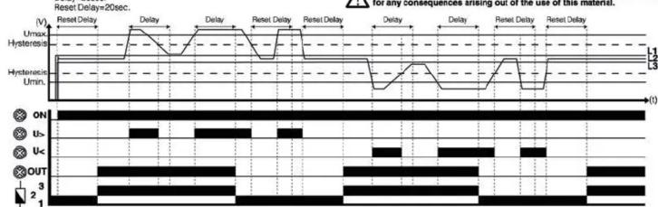
Over and Under Voltage Function Diagram
Delay=20sec.
line
| Signal | Time | |--------|------| | ON | 0 | | U- | 0 | | Uc | 0 | | OUT | 0 |General:
DGRC-01, GKRC-01/02/02F/02FA/03/03F relays are delay-off and delay-on capable voltage monitoring relays which have adjustable over and under voltage limits. They are used in 1-phase and 3-phase Air Conditioning systems, in electronic command and control systems, for protection of capacitors in compensation systems and for protection of equipments like motors.
Utilization and Working Principle:
By using the Over Voltage(Max.) and Under Voltage(Min.) adjustment knobs on the front side, the over and under voltage limits of the system that will be protected is determined.
The Delay knob on the front is used commonly for both the adjusted over voltage faults and adjusted under voltage faults.
The Reset Delay knob on the front is used commonly for all faults. The over voltage and under voltage protection options can be deactivated separately (By adjusting the Max. and Min. knobs to OFF position).
Protection Functions:
a) Over Voltage Monitoring: GKRC-01 / 02 / 02F / 02FA / 03 / 03F / M2 if one or many of the measured voltage(Phase/Phase-Phase) values are over the limit of the device breaks the delay time starts to count. When the Delay time is up, the relay of the device breaks the connection and the 'OUT' light turns off. When all of the measured voltages fail under the adjusted Over Voltage Value, "U>" light turns off and adjusted Reset Delay time is adjusted to the 'OFF' position, and "U" light turns off. When all of the measured voltage(Phase/Phase-Phase) values go over the '1.5x'unit, "U>" light turns on, the relay of the device breaks the connection and the 'OFF' position, and "U" light turns on, the relay of the device breaks the connection and the 'OFF' position, is adjusted to the 'OFF' position, the Over Voltage Protection function is disabled. b) Under Voltage Monitoring: GDRC-01, GKRC-02 / 02F / 02FA / 03 / 03F / M2 if one or many of the measured voltage(Phase/Phase-Phase) values are over the limit of the adjusted Under Voltage Value(μmin), the "U"-light turns on and the adjusted Delay time starts to count. When the Delay time is up, the relay of the device breaks the connection and the 'OFF' position, and "U" light turns on, the relay of the device breaks the connection and the 'OFF' position, is adjusted to the 'OFF' position, and the 'OFF' position, is adjusted to the 'OFF' position, the Over Voltage Protection function is disabled.
c) Phase Sequence Protection: GKRC-02F / 02FA / 03F

If there is a change in the phase sequence for whatever the reason, only the "ON" light turns on and the relay of the device breaks the connection without any delay.
Phase Sequence Fault Diagram
Insufficient Supply Voltage: DGRC-01, GKRC-01 / 02 / 02F / 03 / 03F / M2
DGRC-01, GKRC-01 / 02 / 02F / 03 / 03F / M2 are supplied from a 3 Phase capacitive source. The supply voltage on these devices equals to the mean value of voltages from all three phases. If this mean value is less than half the supply voltage, the relay gives an insufficient supply voltage warning (U< and U> LEDs flash in that order) and the relay breaks contact without delay.
DGRC-01 GKRC-01 / 02 / 02F With Neutral => (VL1+VL2+VL3)/3 < 115 VAC (F-N) GKRC-03 / 03F Without Neutral => (VL12+VL23+VL31)/3 < 200 VAC (F-F)
PRECAUTIONS FOR INSTALLATION AND SAFE USE
- Failure to follow those instructions will result in death or serious injury.
• Disconnect all power before working on equi
- When the device is connected to the network, do not remove the front panel.
Do not try to clean the device with solvent or the like.
- Only clean the device with a dried cloth.
- Verify correct terminal connections when wiring.
- Electrical equipment should be serviced only by your compedent seller.
■Mount device to the pane
No responsibility is assured by the manufacturer or any of its subsidiaries for any consequences arising out of the use of this material.
Connection Diagram
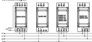
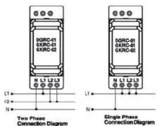
TECHNICAL PROPERTIES
| Measurement and Supply Circuit | |
| Supply Voltage (Un) | 220, 230V AC DGRC-01, GKFC-01/02/02F02FAM2400V AC GKFC-03/03F |
| Supply Voltage Gap (U/V) | Please refer to the side label on the device. |
| Supply Frequency | 48 ... 63 Hz50 / 90 Hz, (GKFC-02F/A) |
| Power Consumption (max.) | 30 VA / 2 W (50 Hz.) |
| Measurement Method | True RMS |
| Settings | |
| Over Voltage Setup (Umax.) | 1.05...1.30× Un (% Scale)240 ... 300V AC (GKFC-01/02/02F/M2)410 ... 510V AC (GKFC-03/03F/02F/A) |
| Under Voltage Setup (Umin.) | 0.7...0.95 × Un (% Scale)150 ... 210 V AC (DGRC-01, GKFC-02/02/F/M2)270 ... 370V AC (GKFC-03/03F/02F/A) |
| Hysteresis(for Umax and Umin) | Un + %3 (constant) |
| Delay-Oil (Delay) | 0.1 20 sec. (0.1 ... 60m, and 0.1 ... 180m Manufactured if demanded ) |
| Delay-On (Reset Delay) | 0.1 20 sec. (0.1 ... 60m, and 0.1 ... 180m Manufactured if demanded ) |
| Voltage Adjustment Accuracy | ± 3% |
| Repetition Accuracy(Voltage) | ± 0.5% |
| Accuracy of the Set Times | ± 5% + 100 msec. |
| Repetition Accuracy(Time) | ± 3% |
| Output | |
| Output Type | 1 Inverter, 6A, 25W, 200VA (Cotsp=1) |
| Electrical Life | 10 ^ |
| Mechanical Life | 10 ^ |
| Ambient Conditions | |
| Operating Temperature | -5°C ... +5°C |
| Relative Humidity | <%80 (without condensation) |
| Connection | |
| Cable Cross-sections for Terminals | 4mm ^2 (12/AVG) stranded rigid cable6mm ^2 (10/AVG) solid conductor cable2x2.5mm ^2 (14/AVG) solid conductor cable |
| Screw-On Force | 0.5 km (4.5in bus) |
| Body | |
| Insulation | Inside the panel vertically or on to the rail |
| Material Type | Plastic Consistent with UL, 94 VD |
| Protection Class | IP 20 (Terminals), IP 40 (Front Panel) |
| Dimensions | Type PK, 28 |
| Weight | 100 gr. (Only GKFC-02FA 200 gr.) |
| Isolation | |
| Isolation Voltage (EN 60255-5) | 400 V |
| Isolation Coordination(EN 60255-5) | Exceeding Voltage Category III, Pollution Degree 3 |
| Intriant Burst Voltage (EN 60255-5) | 4 KW 1.2 / 90 uS |
| Dielectric Resistance (EN 60255-5) | 2 KW AC 50 Hz, 1 minute. |
| Isolation Resistance (EN 60255-5) | >500 MOHM / 600 V DC |
| Followed Standards | |
| EN-60255-6 | Product Standard |
| EN-61000-6-2 | Immunity |
| EN-61000-6-3, EN-61000-6-4 | Emission |
| Directives/Regulations To Be Followed | |
| 73/23/EEC | LVD |
| 89/336/EEC | EMC |
Dimensions (mm)

Note: The contact resistance at ohmic load (eg: Incandescent bulb, Resistance devices) is 8A. It is recommended to use a contactor if the inductive load eg: AC motor, fluorescent, etc.) or capacitive load (eg: Led Drivers, UPS, Fluorescent (Electronic Ballast), etc.) switch. Otherwise adhesion may occur in relay contacts.

Brand : ENTES
Model : GKRC-02FA
Category : Uncategorized