MKC-04-U69 - Uncategorized ENTES - Free user manual and instructions
Find the device manual for free MKC-04-U69 ENTES in PDF.


| Product Type | Power Factor Controller |
| Model | MKC-04-U69 |
| Brand | ENTES |
| Measurement Input | 3-phase voltage and current (up to 690V) |
| Power Supply | 100-240V AC/DC, 50/60Hz |
| Display | Backlit LCD, 4 lines |
| Output Relays | 4 relay outputs for capacitor bank switching |
| Communication | RS485 Modbus RTU |
| Protection Class | IP54 (front panel) |
| Operating Temperature | -10°C to +55°C |
| Dimensions (WxHxD) | 144 x 144 x 80 mm |
| Weight | 0.5 kg |
| Enclosure Material | ABS plastic, self-extinguishing |
| Standards | IEC 61000-6-2, IEC 61000-6-4 |
| Installation Type | Panel mount, cutout 138x138 mm |
| Wiring | Screw terminals, 2.5 mm² max |
| Harmonic Analysis | Up to 31st harmonic |
| Target Power Factor | Adjustable from 0.8 inductive to 0.8 capacitive |
| Switching Delay | Adjustable from 1 to 999 seconds |
| Memory for Settings | EEPROM, retains data on power loss |
Frequently Asked Questions - MKC-04-U69 ENTES
User questions about MKC-04-U69 ENTES
0 question about this device. Answer the ones you know or ask your own.
Ask a new question about this device
Download the instructions for your Uncategorized in PDF format for free! Find your manual MKC-04-U69 - ENTES and take your electronic device back in hand. On this page are published all the documents necessary for the use of your device. MKC-04-U69 by ENTES.
USER MANUAL MKC-04-U69 ENTES
PHASE FAILURE RELAYS
MKC-04-U69/06-U69
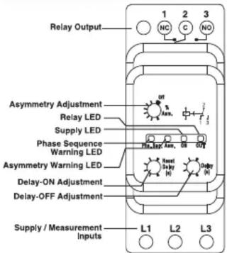
| Prc. | Asn. | On | Out | Meanings of the Device LEDs |
| ○ | ○ | ● | ● | Voltage(s) is(are) within limits |
| ○ | ● | ● | ○ | Voltage(s) is(are) out of limits |
| ● | ○ | ● | ○ | Phase Sequence Fault Warning |
| ● | ● | ● | ○ | Phase Fault Warning |
| ○ | ○ | ● | ○ | Unsufficient Supply Warning |
●:LED ON
Q:LED OFF
①:Flashing
General
One of the common faults encountered in industrial plants is the overheating and the resulting damaging of the 3-phase motors due to the phase failure. Thermal-magnetic relay, which is an essential element in motor protection is generally too slow to assure demurrage without tripping due to both
its electromechanical structure and the use of high current setting range. MKC-06-U69 Motor Protection Relays which are designed to protect the desired equipment against phase failure for 690 V phase-phase voltages, asymmetry and phase sequence failure on 3 phase systems are manufactured to serve the following purposes.
Utilisation and Working Principle
By using the asymmetry adjustment knob(%asm.) on the front panel, the upper asymmetry limit of the system which will be protected is determined. If the unbalance on the system(asymmetry) exceeds the adjusted value, the device waits as long as the Delay-OFF time(Delay) and if the unbalance is still over the adjusted value, the relay of the device breaks contact(OUT LED turns off and Asm. LED turns on). If the unbalance on the system(asymmetry) falls under the adjusted value, the device waits as long as the Delay-ON time(Reset Delay) and if the unbalance is still under the adjusted value, the relay of the device makes contact(OUT LED turns on and Asm. LED turns off).
PROTECTION FEATURES :
1- Voltage Unbalance
(MKC-06-U69 - Can be Adjusted or Disabled)(MKC-04-U69 - Fixed %10)
Unbalanced voltage(asymmetry) may occur when;
The mains are loaded with unbalanced distribution,
One of the 3 phases of the motor has lost. In this case, some amount of voltage which is produced by other phases will be induced on the lost phase. Amount of this voltage depends on both the motor type and amount of load.
Output relay is making contact when a phase has been lost or an unbalanced Phase-Phase voltage value, which is occurred for any reason, is smaller than the user defined asymmetrical value. If this unbalanced voltage value exceeds the adjusted asymmetrical value(5-15%); output relay will break contact and switch off the motor at the end of adjusted time delay(0.1-20 sec.); relays LED on the front panel is turned off. Asymmetry error LED is turned ON. If the fault disappears within the delay time, the output relay will not break contact and will not switch off the motor.
In applications; a proper asymmetrical value should be adjusted considering the induced voltage value in two-phase which are remained after the other one has lost.
Example: On a 3 x 380 V network, switching value in case of 10% asymmetry
$$ \frac {(3 8 0 - \min)}{(\min + 3 8 0 + \min) / 3} \times 1 0 0 = \% 1 0 \quad \Rightarrow \quad \frac {3 8 0 - \min}{(3 8 0 + 2 ^ {*} \min)} = \frac {1}{3 0} \quad \Rightarrow \quad \min = 3 4 4. 3 V $$

Phase Sequence Fault Function Diagram
2- Phase Sequence Protection When the phase sequence is incorrect (L1, L2, L3 not in clockwise direction) the motor is not activated. If the sequence is changed by any reason, the output relay switches OFF immediately. Relay LED turns OFF, Phase Sequence error LED turns ON.
3-Lost Phase Fault
If the value for any of the phases drop down the lost phase limit value (160 V), Phs.Seq. - Asm. LEDs turn on simultaneously and the relay breaks contact without delay.
4- Insufficient Supply Voltage
If the average of Phase-Phase voltages falls below 160V, device creates insufficient supply voltage error (Asm. and Phs. Seq. LEDs start to blink one after the other) and the relay releases without any delay.
Precautions For Installation and Safe Use
Failure to follow those instructions will result in death or serious injury.
- Disconnect all power before working on equipment.
- When the device is connected to the network, do not remove the front panel.
- Do not try to clean the device with solvent or the like. Only clean the device with a dried cloth.
- Verify correct terminal connections before operation.
- Mount device to the panel.
- Electrical equipment should be serviced only by your compedent seller.
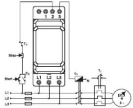
Connect a start /stop button as shown in the connection diagram.
A switch or circuit breaker can be used on the supply of the equipment.
Connection Diagrams
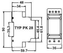
Dimensions (mm)
TECHNICAL PROPERTIES
| Measurement and Supply Circuit | |
| Supply Voltage (Un) | 160-690 V AC |
| Supply Frequency | 50/60 Hz. |
| Power Consumption (max.) | 30 VA / 2 W (50 Hz.) |
| Measurement Method | True RMS |
| Settings | |
| Asymmetry (asm. %) | MKC-06-U69 (5%...15% Can be disabled), MKC-04-U69 (10%) |
| Hysteresis | 30% of the adjusted asymmetry value |
| Delay-Off(Delay) | 0.1 ... 20 sec. |
| Delay-On(Reset Delay) | 0.1 ... 20 sec. |
| Repetition Accuracy(Voltage) | ± 0.5% |
| Repetition Accuracy(Time) | ± 0.5% |
| Output | |
| Output Type | 1 Change-over(CO) Contact, 8A, 250V, 2000VA (Cosφ=1) |
| Electrical Life | 10^5 |
| Mechanical Life | 10^7 |
| Connection | |
| Cable Cross-sections for Terminals | 4 mm^2( 12AWG) stranded rigid cable 6 mm^2( 10AWG) solid conductor cable |
| Screw-On Force | 0.5 Nm (4.5in.lbs) |
| Body | |
| Installation | Inside the panel vertically or on to the rail |
| Material Type | Plastic Compliant with UL 94 VO |
| Protection Class | IP 20 (Terminals), IP 40 (Front Panel) |
| Dimensions | Type PK 28 |
| Weight | 100 gr. |
| Followed Standards | |
| Impulse voltage resistance / rated value | 6kV |
| Recorded real power | 2W |
| Protection class IP | IP20 |
| Electromagnetic compatibility | IEC 60947-1 / IEC 61000-6-2 / IEC 61000-6-4 |
| Resistance against vibration / according to IEC 60068-2-6 | 1 ... 6 Hz: 15 mm, 6 ... 500 Hz: 2g |
| Resistance against shock / according to IEC 60068-2-27 | sinusoidal half-wave 15g / 11 ms |
| Installation altitude / at a height over sea level / maximum | 2000 m |
| Conductor-bound parasitic coupling BURST / according to IEC 61000-4-4 | 4 kV |
| Conductor-bound parasitic coupling conductor-earth SURGE / according to IEC 61000-4-5 | 4 kV |
| Electrostatic discharge / according to IEC 61000-4-2 Field-bound parasitic coupling / | 6 kV contact discharge / 8 kV air discharge |
| according to IEC 61000-4-3 Insulation voltage / for overvoltage | 10 V/m |
| category III according to IEC 60664 / with degree of pollution 3 / rated value | 690V |
| Degree of pollution | 2 |
| Ambiant Conditions | |
| Degree of pollution Ambient temperature | during operating °C -25 ... +60 during storage °C -40 ... +85 during transport °C -40 ... +85 <%90 (without condensation) |
| Relative Humidity Galvanic isolation | between entrance and outlet Yes between the outputs Yes between the voltage supply and other circuits Yes |

No responsibility is assured by the manufacturer or any of its subsidiaries for any consequences arising out of the use of this material.
Note: The contact resistance at ohmic load (eg: Incandescent bulb, Resistance devices) is 8A. It is recommended to use a contactor if the inductive load eg: AC motor, fluorescent, etc.) or capacitive load (eg : Led Drivers, UPS, Fluorescent (Electronic Ballast), etc.) switch. Otherwise adhesion may occur in relay contacts.
MOTOR (FAZ) KORUMA RÖLESİ MKC-04-U69/06-U69

- PHASE FAILURE RELAYS
- MKC-04-U69/06-U69
- General
- Utilisation and Working Principle
- PROTECTION FEATURES :
- 1- Voltage Unbalance
- (MKC-06-U69 - Can be Adjusted or Disabled)(MKC-04-U69 - Fixed %10)
- 3-Lost Phase Fault
- 4- Insufficient Supply Voltage
- Precautions For Installation and Safe Use
- MOTOR (FAZ) KORUMA RÖLESİ MKC-04-U69/06-U69
Brand : ENTES
Model : MKC-04-U69
Category : Uncategorized