PAT-95 - Meter Sonel - Free user manual and instructions
Find the device manual for free PAT-95 Sonel in PDF.


| Product Type | Portable Appliance Tester (PAT) |
| Model | PAT-95 |
| Brand | Sonel |
| Dimensions (W x H x D) | 318 x 257 x 152 mm |
| Weight | Approx. 5 kg |
| Power Supply | Mains 195–265 V, 45–70 Hz; rechargeable Ni-MH 7.2 V / 2 Ah |
| Display | LCD, color capacitive touchscreen 5", 1280x720 pixels, 500 cd/m² |
| Measurement Categories | CAT II 300 V (EN 61010-1) |
| Ingress Protection | IP40 |
| Main Functions | Protective conductor resistance (200 mA, 10 A, 25 A), insulation resistance (100 V, 250 V, 500 V, 1000 V), substitute/PE/differential/touch leakage current, RCD/PRCD testing, functional test (power, current, voltage, THD), IEC cord test, visual test |
| Memory | Up to 9999 results |
| Data Transmission | USB-A, USB-B, Wi-Fi (2.4/5 GHz), LAN |
| Bluetooth | v4.2 Classic, BLE; frequency 2400–2483.5 MHz; GFSK/π/4DQPSK/8DPSK Modulation |
| Operating Temperature | -10 °C to +50 °C |
| Storage Temperature | -20 °C to +70 °C |
| Humidity | 20–80% RH |
| Safety Standards | EN 50678, EN 50699, EN 61557-6, VDE 0404, AS/NZS 3760 |
| Maintenance | Clean casing with soft damp cloth and mild detergent; clean probes with water; no solvent; electronic system maintenance-free |
| Spare Parts / Repairability | Fuses: 5x20 mm 16 A/250 V AC fast-acting; repairs only by authorized service point |
| General Information | Part of Sonel MeasureEffect™ platform; software: PAT Analysis, PAT Analysis Mobile |
Frequently Asked Questions - PAT-95 Sonel
User questions about PAT-95 Sonel
0 question about this device. Answer the ones you know or ask your own.
Ask a new question about this device
Download the instructions for your Meter in PDF format for free! Find your manual PAT-95 - Sonel and take your electronic device back in hand. On this page are published all the documents necessary for the use of your device. PAT-95 by Sonel.
USER MANUAL PAT-95 Sonel
natural_image
Top-down line drawing of a spacecraft's internal components (no text or symbols)User manual
PAT-95 · PAT-96
Portable appliance tester

CE
User manual
PAT-95 · PAT-96
Portable appliance tester
SONEL S.A.
Wokulskiego 11
58-100 Świdnica
Poland
Version 1.01 12.06.2024
The PAT-95/96 meter is a modern, top quality measuring instrument which is easy and safe to use, provided that the principles presented in this manual are observed.
PAT-96 | The icon with the meter name is placed next to sections of the text that refer to specific features of the device. All other parts of the text relate to all types of the device.
MeasureEffect™
Welcome to the Sonel MeasureEffect™ platform. It is a comprehensive system that enables you to take measurements, store and manage data, and provides multi-level control of your instruments. You can find a detailed description of the system in the dedicated user manual.
The manual can be found on the manufacturer's website. Check www.sonel.com > EN > Download > User manuals (Software section) and the instrument page (Files section).
CONTENTS
1 General information....4
1.1 Safety symbols 4
1.2 Behaviour of signalling LEDs....4
1.3 Safety....5
1.4 General characteristics....6
1.5 Compliance with standards 7
2 Quick start 8
3 Interface....9
4 Data transmission....10
4.1 Set of accessories to connect the meter to a PC 10
4.2 Data transmission through USB port....10
6 Power supply....12
6.1 Battery power 13
6.2 Charging rechargeable battery....13
6.3 Power supply from mains 13
6.4 General principles regarding using Ni-MH rechargeable batteries 14
7 Cleaning and maintenance ....15
8 Storage....15
9 Dismantling and utilisation....15
10 Technical data....16
10.1 Basic data....16
10.1.1 Measurement of network parameters.... 16
10.1.2 Measurement of PE resistance 16
10.1.3 Measurement of insulation resistance....18
10.1.4 Measurement of leakage current....20
10.1.5 Testing RCDs / PRCDs 22
10.1.6 Functional test 23
10.1.7 PAT-96 | Measurement of welding machine voltage without load 24
10.2 Operating data....25
10.3 Additional data....26
10.3.1 Additional uncertainties according to EN IEC 61557-2 (R _ISO )....26
10.4 Inverter characteristics 26
11 Manufacturer 27
1 General information
1.1 Safety symbols
The following international symbols are used in the device and/or in this manual:
 | Refer to the user manual for additional information and explanations | [T6X5] | Ground |  | AC current/voltage |
 | DC current/voltage |  | Double insulation (protection class) |  | Declaration of Conformity with EU directives (Conformité Européenne) |
 | Do not dispose of with other household waste |  | Attention, risk of electric shock |
flowchart
graph TD
    A["Utility Line"] --> B["Solar House"]
    B --> C["DC"]
    C --> D["DB1"]
    C --> E["AC"]
    D --> F["Light Bulb"]
    E --> G["Light Bulb"]
    H["HV"] --> I["LV"]
    J["BAT IV"] --> K["DB2"]
    L["BAT III"] --> M["DB2"]
    N["BAT II"] --> O["Light Bulb"]
    P["Light Bulb"] --> Q["Light Bulb"]
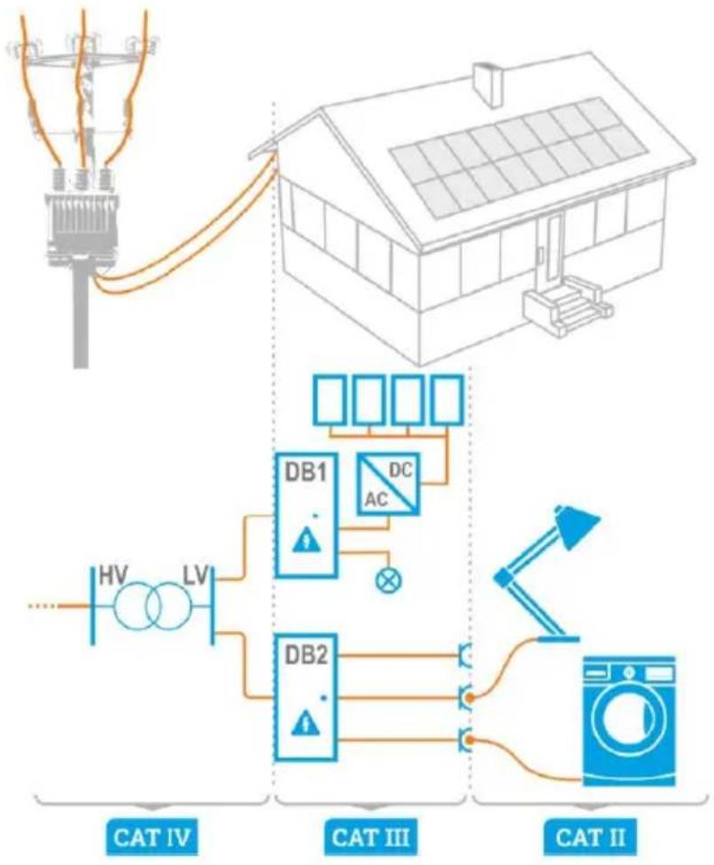
Measurement categories according to EN IEC 61010-2-030:
- CAT II – concerns measurements performed in circuits directly connected to low voltage installations,
- CAT III – concerns measurements performed in buildings installations,
- CAT IV – concerns measurements performed at the source of low voltage installation.
1.2 Behaviour of signalling LEDs

The LED is on continuously

The LED flashes slowly

The LED flashes rapidly
1.3 Safety
To avoid electric shock or fire, as well as provide the conditions for correct operation and accuracy of obtained results, you must observe the following guidelines:
- Before you proceed to operate the device, acquaint yourself thoroughly with this manual and observe the safety regulations and specifications defined by the producer.
- Any application that differs from those specified in this manual may result in damage to the device and constitute a source of danger for the user.
- The device must be operated solely by appropriately qualified personnel with relevant certificates to realise measurements of electric installation. Operating the meter by unauthorised personnel may result in damage to the device and constitute a source of danger for the user.
- Using this manual does not exclude the need to comply with occupational health and safety regulations and with other relevant fire regulations required during the performance of a particular type of work.
- The device must not be used for networks and devices in areas with special conditions, e.g. fire-risk and explosive-risk areas.
- Before starting the work, check the device, wires, adapters and other accessories for any sign of mechanical damage. Pay special attention to the connectors.
- It is unacceptable to operate:
it is damaged and completely or partially out of order,
⇒ its cords and cables have damaged insulation,
⇒ of the device and accessories mechanically damaged,
it was stored for an excessive period of time in disadvantageous conditions (e.g. excessive humidity) After moving the device from a cool to a warm place with a high level of relative humidity, do not start measurements until the device is warmed up to the ambient temperature (approximately 30 minutes).
- Before measurement, choose a correct measurement function and make sure that the test leads are connected to their respective measuring terminals.
- The correct operation of the instrument and accessories must be checked regularly to avoid any hazard which may result from erroneous results.
- In a situation where the product works with other instruments or accessories, the lowest measurement category of the connected devices is used.
- Do not power the meter from sources other than those listed in this manual.
- The tester may be powered only from grounded mains sockets.
- Repairs may only be performed by an authorised service point.
WARNING
Do not touch the tested device during measurements.

NOTE!
- During the measurement of S, P, Q, I A , I PE and I _T , PE of the power supply socket is connected to PE of the test socket.
- Adapters for three-phase sockets and for 32 A industrial sockets must not be used for the following measurements: leakage currents I_PE and I_ , power and current consumption (for detailed information on the use of adapters see PAT adapter's user manual).
- Only accessories for a given device should be used. Using other accessories may cause damage to measuring terminals, introduce additional measurement error and create a risk for the user.

- Test sockets and the socket for testing IEC cords are protected against improper connection to the voltage up to 300 V AC for 60 seconds.
- Due to continuous development of the meter's software, the actual appearance of the display for some features may slightly differ from that presented in this user manual. The latest version of the manual is provided on the manufacturer's website.
- An attempt to install drivers in 64-bit Windows 8 and Windows 10 may result in displaying "Installation failed" message.
- Cause: Windows 8 by default blocks drivers without a digital signature.
- Solution: Disable the driver signature enforcement in Windows
1.4 General characteristics
The meter is intended to measure the basic parameters of portable electrical appliances (power tools, household appliances, etc.) important for their safety: protective conductor resistance, insulation resistance, continuity of connections, leakage current and RCDs.
Basic functions of the instrument:
• Measurement of network voltage and frequency
• Measurement of protective conductor resistance (protection class - I)
• Measurement of insulation resistance
• Measurement of substitute leakage current
• Measurement of PE leakage current
• Measurement of differential leakage current
• Measurement of touch leakage current
• PAT-96 | Measurement of welding machine parameters
• Measurement of power P, Q and S
• Measurement of current consumption
• Measurement of RCD / PRCD parameters
- Visual test
- IEC cord test
1.5 Compliance with standards
The tester meets the requirements of the following standards:
- EN 50678 General procedure for verifying the effectiveness of the protective measures of electrical equipment after repair
• EN 50699 Recurrent Tests of Electrical Equipment
The tester may be used to test equipment in accordance with the following standards:
• EN 60745-1 Hand-held motor-operated electric tools. Safety. Part 1: General requirements.
• EN 61029 Safety of transportable motor operated electric tools. General requirements.
• EN 60335-1 Household and similar electrical appliances. Safety. Part 1: General requirements.
- EN 60950 Information technology equipment – Safety- Part 1: General requirements.
- EN 61557-6 Electrical safety in low voltage distribution systems up to 1000 V AC and 1500 V DC - Equipment for testing, measuring or monitoring of protective measures - Part 6: Effectiveness of residual current devices (RCD) in TT, TN and IT systems.
- VDE 0404-1 Testing and Measuring Equipment for Checking the Electric Safety of Electric Devices - Part 1: General Requirements.
- VDE 0404-2 Testing and Measuring Equipment for Checking the Electric Safety of Electric Devices - Part 2: Testing Equipment for Tests after Repair, Change or in Case of Repeat Tests.
• VDE 0701-0702 Inspection after Repair, Modification of Electrical Appliances.
- Repeat Testing of Electrical Equipment. General Requirements for Electrical Safety.
• AS/NZS 3760:2010 In-service safety inspection and testing of electrical equipment.
2 Quick start

When you start the device for the first time, you must set the interface language and create a user account. Finally, set the date, time and time zone.
| 1 | Turn the meter on. | |
| 2 | Create or log in to a user account. | |
| 3 | Enter the meter settings | |
| 4 | Select measurement. You can find information about it under @on and in the Sonel MeasureEffectTM platform manual. | |
| 5 | Enter the measurement settings. | |
| 6 | Connect the meter to the tested object. | |
| 7 | Start the measurement. | |
| 8 | End the measurement or wait for it to be completed. Then you can enter additional information about the measurement. | |
| 9 | Save the result in the memory. | |
| 10 | Turn the meter off. | |

- After switching on, the tester performs a self-test to check its correct operational condition. When this test is successfully completed, the tester automatically performs the following measurements:
• voltage between L and N of power supply,
• measurement of mains frequency,
- checking the continuity PE in the power supply socket,
• measuring the voltage between N and PE in the power supply socket,
• indicates swapped L and N terminals
- For mains voltages below 195 V and above 256 V all test functions are automatically blocked.
- You can save measurements in two ways:
- by performing a measurement and then assigning it to an object in the memory structure
- entering an object in the memory structure and making a measurement at this memory location

Additional information displayed by the meter
| Voltage on the meter! | Voltage UN-PE > 25 V or lack of PE continuity, measurements are blocked. |
| Too high U L-N! | Mains voltage > 265 V, measurements are blocked. |
 | Correct polarity of power supply (L and N), measurements possible. |
 | Incorrect polarity of power supply, swapped L and N in the power supply socket of the tester. The meter automatically swaps L and N in the test socket – measurements are possible. |

- Error message indicating incorrect voltage frequency may be caused by supplying power from an unstable voltage source (e.g. generator).
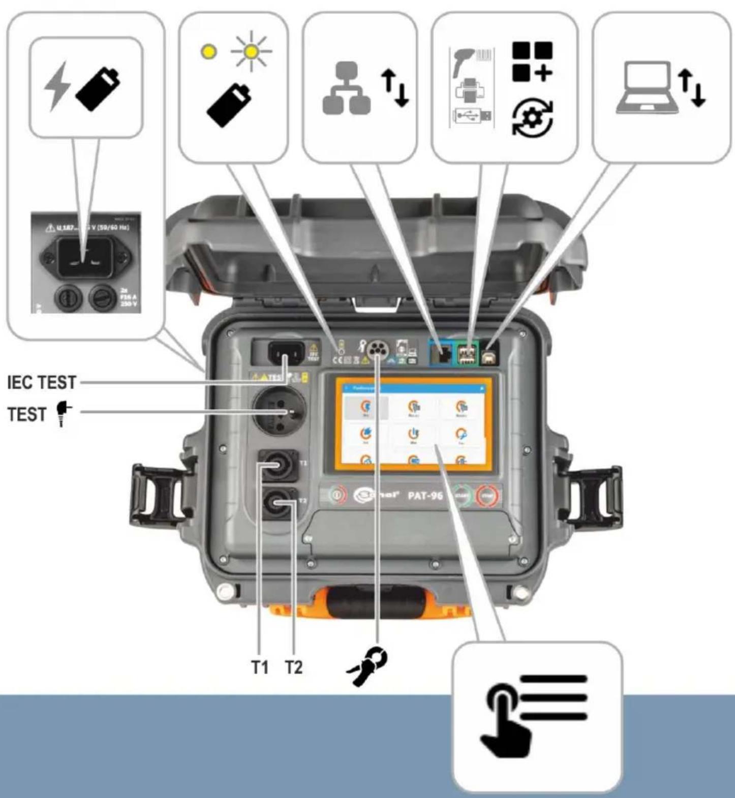
- To customize the newly bought reader DS4203 / DS4208 to cooperation with the PAT tester, connect it to the USB socked of turned on computer and read the code below.

3 Interface


- Turn on the meter (short press)
- Turn off the meter (press and hold)
- Call up the brightness and volume menu (press briefly when the meter is on)

Start measurement

Stop measurement
4 Data transmission
4.1 Set of accessories to connect the meter to a PC
In order to ensure the communication of the meter with a computer a USB cable and the relevant software are required:
- Sonel PAT Analysis,
- Sonel PAT Analysis Mobile.
The software may be used for many devices manufactured by SONEL S.A. which are equipped with a USB interface. Detailed information is available from the manufacturer and distributors.
If the required software has not been purchased with the meter, it may be obtained from the manufacturer or from an authorised distributor.
4.2 Data transmission through USB port
1

Enter the USB mode on the meter.
2

Use the USB cable to connect the meter to the computer.
3

Start the software for data transfer. During data transmission, all buttons on the meter are locked, except for those responsible for interrupting the transmission and switching off the device.
5 Fuse replacement
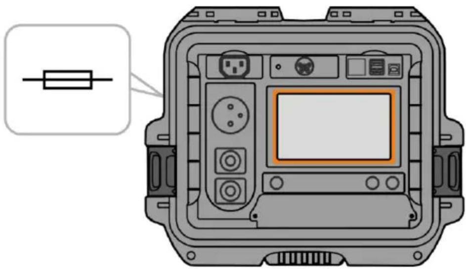
The device is protected by two fast-acting fuses 5 x 20 mm 16 A / 250 V AC. To replace the fuse, unscrew the socket head, place a working fuse in place of the damaged fuse, and then screw on the socket head.
natural_image
Front view of a device control panel with labeled buttons and an indicator light (no text or symbols on the panel itself)
NOTE!
Do not use fuses other than those listed in this manual.
6 Power supply

NOTE!
Before operating the meter, discharge the battery and then fully charge it, so that the indication of its charged status is correct.
The charge level of the rechargeable battery is indicated by the symbol in the right upper corner of the display on a permanent basis.

Battery charged.

Charging voltage too high. Change the charger or power supply source.

Battery completely discharged – charge it. All measurements are blocked. The meter will turn off automatically when the battery charge drops to a critical level.

Battery temperature out of permissible range. If a charging is in progress, it will be aborted.

Charging of the battery is in progress.

No battery. The meter operates on an external power supply.

Battery failure. It is recommended to replace it with a new one.

Battery status unknown. Contact the customer service centre.

Additional information displayed by the meter
natural_image
Diagram of a device control panel with a battery icon and indicator light (no text or symbols)
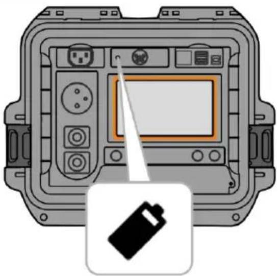
Battery discharged

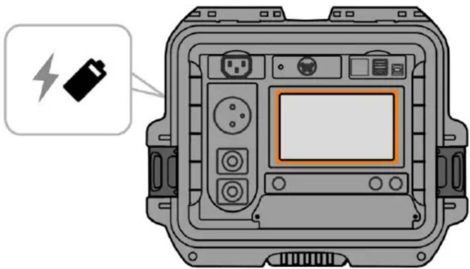
Charging of the battery is in progress / the battery is charged
6.1 Battery power
The meter is powered by a Ni-MH battery. The whole device is powered via the power cord.
natural_image
Front view of a device control panel with battery icon and indicator lights (no text or symbols)
NOTE!
Do not power the meter from sources other than those listed in this manual.
6.2 Charging rechargeable battery
Charging starts once the power supply has been connected to the meter, regardless of whether the meter is on or off. The charging status is indicated on the display and by an active LED.
When the meter is turned off by ⏻ button or by AUTO-OFF, the charging process is not stopped.
Indication of completed charging is shown by: 100%
6.3 Power supply from mains
It is possible to charge the battery when carrying out the measurements. To do this, just connect the power cable to the meter.
When the meter is turned off by button or by AUTO-OFF, the charging process is not stopped.
6.4 General principles regarding using Ni-MH rechargeable batteries
- If you do not use the device for a prolonged period of time, then it is recommended to remove the rechargeable batteries and store them separately.
- Store the accumulators in a dry, cool and well ventilated place and protect them from direct sunlight. The temperature of the environment in the case of prolonged storage should not exceed 30^ C. If the rechargeable batteries are stored for a long time in a high temperature, then the occurring chemical processes may reduce their lifetime.
- Rechargeable batteries NiMH usually lasts for 500-1000 charging cycles. The rechargeable batteries reach their maximum capacity after being formatted (2-3 charge and discharge cycles). The most important factor which influences the lifetime of a rechargeable battery is the level of its discharging. The deeper the discharge level of the batteries, the shorter their lifetime.
- The memory effect is limited in the case of NiMH batteries. These batteries may be charged at any point with no serious consequences. It is however, that every few cycles, they are completely discharged.
- During storage of Ni-MH rechargeable batteries they are discharged at the rate of approximately 30% per month. Storing batteries in high temperatures may increase this process even twofold. In order to prevent excessive discharge of rechargeable batteries, after which it would be necessary to format them, it is recommended to charge them from time to time (even if they are not used).
- Modern fast chargers detect both too low and too high a temperature of the battery pack and react to the situation adequately. Too low temperature should prevent starting the process of charging, which might irreparably damage rechargeable batteries. An increase of the temperature of the rechargeable batteries is a signal to stop charging and is a typical phenomenon. However charging at a high ambient temperature apart from reducing batteries' lifetime causes an accelerated increase of their temperature and the result is that the batteries are not charged to their full capacity.
- Please note that when the batteries are charged with a fast-charger they are charged only to approx. 80% of their capacity - better results can be achieved by continuing charging: the charger enters trickle-charging mode and during the next few hours batteries are charged to their full capacity.
- Do not charge or use the batteries in extreme temperatures. Extreme temperatures reduce the lifetime of batteries and rechargeable batteries. Avoid placing devices powered by rechargeable batteries in very hot environments. The nominal working temperature must be absolutely observed.
7 Cleaning and maintenance

NOTE!
Use only the maintenance methods specified by the manufacturer in this manual.
The casing of the meter may be cleaned with a soft, damp cloth using all-purpose detergents. Do not use any solvents or cleaning agents which might damage the casing (powders, pastes, etc.).
Clean the probe with water and dry it.
The test leads should be cleaned with water and detergents, and then dried.
The electronic system of the meter does not require maintenance.
8 Storage
In the case of storage of the device, the following recommendations must be observed:
- disconnect all the test leads from the meter,
- clean the meter and all its accessories thoroughly,
- wind the test leads,
- in order to prevent a total discharge of the battery pack in the case of a prolonged storage, charge the device at least once every six months.
9 Dismantling and utilisation
Worn-out electric and electronic equipment should be gathered selectively, i.e. it must not be placed with waste of another kind.
Worn-out electronic equipment should be sent to a collection point in accordance with the regulations valid in a given region.
Before the equipment is sent to a collection point, do not dismantle any elements.
Observe local regulations concerning disposal of packages, waste batteries and rechargeable batteries.
10 Technical data
10.1 Basic data
⇒ The abbreviation "m.v." used in the specification of accuracy denotes a measured value
⇒ Ranges and accuracies are additionally provided according to DIN VDE 404-1
10.1.1 Measurement of network parameters
Measurement of network voltage
| Display range | Resolution | Accuracy |
| 95.0 V...265.0 V | 0.1 V | ±(2% m.v. + 2 digits) |
• Measurement of the mains voltage between L and N of the power supply
Measurement of network frequency
| Display range | Resolution | Accuracy |
| 45.0 Hz...65.0 Hz | 0.1 Hz | ±(2% m.v. + 2 digits) |
- Measurement of the mains voltage frequency of the power supply
- For the set value of 50 Hz, the range is 45...55 Hz
- For the set value of 60 Hz, the range is 55...65 Hz
Measurement of voltage occurring in PE line
| Display range | Resolution | Accuracy* |
| 0.0 V...59.9 V | 0.1 V | ±(2% m.v. + 2 digits) |
*For U < 5 V accuracy is not specified
• Measurement of the mains voltage between PE and N of the power supply
10.1.2 Measurement of PE resistance
Measurement of resistance of protective conductor I = 200 mA (only Protection Class I)
| Display range | Resolution | Accuracy |
| 0.00 Ω...0.99 Ω | 0.01 Ω | ±(4% m.v. + 2 digits) |
| 1.00 kΩ...19.99 Ω | ±(4% m.v. + 3 digits) |
| Influencing factor | Designation | Additional uncertainty |
| Position | E_1 | 0% |
| Supply voltage | E_2 | 0% |
| Temperature | E_3 | 0.1%/°C for R ≥ 0.5 Ω0%/°C for R < 0.5 Ω |
- Unloaded output voltage: 4 V...12 V AC
• Test current: ≥200 mA for R = 0.2 Ω...1.99 Ω - Adjustable upper limit in the range of: 10 mΩ ...1.99 Ω with resolution 0.01 Ω
- Adjustable measuring time: 3 s...180 s with a resolution of 1 s and option Continuous test
Measurement of resistance of protective conductor I = 10 A (only Protection Class I)
| Display range | Resolution | Accuracy |
| 0 mΩ...999 mΩ | 1 mΩ | ±(3% m.v. + 4 digits) |
| 1.00 Ω...1.99 Ω | 0.01 Ω |
| Influencing factor | Designation | Additional uncertainty |
| Position | E_1 | 0% |
| Supply voltage | E_2 | 0% |
| Temperature | E_3 | 0.1%/°C |
- Unloaded output voltage: <12 V AC
• Test current: ≥10 A for R ≤ 0.5 Ω
- Adjustable upper limit in the range of: 10 mΩ ...1.99 Ω with resolution 0.01 Ω
- Adjustable measuring time in the range of: 3 s...180 s with resolution of 1 s
Measurement of resistance of protective conductor I = 25 A (only Protection Class I)
| Display range | Resolution | Accuracy |
| 0 mΩ...999 mΩ | 1 mΩ | ±(3% m.v. + 4 digits) |
| 1.00 Ω...1.99 Ω | 0.01 Ω |
| Influencing factor | Designation | Additional uncertainty |
| Position | E_1 | 0% |
| Supply voltage | E_2 | 0% |
| Temperature | E_3 | 0.1%/°C |
- Unloaded output voltage: <12 V AC
• Measuring current ≥25 A achieved for:
- U_L - N > 180 ~V and R ≤ 0.2
- U_L-N ≤ 180 ~V and R ≤ 0.1
- Adjustable upper limit in the range of: 10 mΩ ...1.99 Ω with resolution 0.01 Ω
- Adjustable measuring time in the range of: 3 s...180 s with resolution of 1 s
10.1.3 Measurement of insulation resistance
Measurement of insulation resistance using test voltage of 100 V
Test range according to IEC 61557-2 for U_N = 100 V: 100 kΩ...99.9 MΩ
| Display range | Resolution | Accuracy |
| 0 kΩ...1999 kΩ | 1 kΩ | ±(5% m.v. + 8 digits) |
| 2.00 MΩ...19.99 MΩ | 0.01 MΩ | |
| 20.0 MΩ...99.9 MΩ | 0.1 MΩ |
| Influencing factor | Designation | Additional uncertainty |
| Position | E_1 | 0% |
| Supply voltage | E_2 | 0% |
| Temperature | E_3 | 0.1%/°C |
| Capacitance | E_7 | 0% for R ≤ 20 MΩunspecified for R > 20 MΩ |
- Accuracy of generated voltage (R LOAD [Ω] ≥ 1000*U N [V]): -0+30% from the set value
• Nominal current: max. 1.4 mA - Adjustable lower limit within the range of 0.1 MΩ...9.9 MΩ with resolution of 0.1 MΩ
- Adjustable measuring time: 3 s...3 min with a resolution of 1 s and option Continuous test
• Detection of a dangerous voltage before commencing a measurement - Discharging the tested object

For R < 100 kΩ the accuracy is not specified.
Measurement of insulation resistance using test voltage of 250 V
Test range according to IEC 61557-2 for U_N = 250 V: 250 kΩ...199.9 MΩ
| Display range | Resolution | Accuracy |
| 0 kΩ...1999 kΩ | 1 kΩ | ±(5% m.v. + 8 digits) |
| 2.00 MΩ...19.99 MΩ | 0.01 MΩ | |
| 20.0 MΩ...199.9 MΩ | 0.1 MΩ |
| Influencing factor | Designation | Additional uncertainty |
| Position | E_1 | 0% |
| Supply voltage | E_2 | 0% |
| Temperature | E_3 | 0.1%/°C |
| Capacitance | E_7 | 0% for R ≤ 20 MΩunspecified for R > 20 MΩ |
- Accuracy of generated voltage (R LOAD [Ω] ≥ 1000*U N [V]): -0%+30% from the set value
• Nominal current: max. 1.4 mA - Adjustable lower limit within the range of 0.1 MΩ...9.9 MΩ with resolution of 0.1 MΩ
- Adjustable measuring time: 3 s...3 min with a resolution of 1 s and option Continuous test
- Detection of a dangerous voltage before commencing a measurement
- Discharging the tested object

For R < 250 kΩ the accuracy is not specified.
Test range according to IEC 61557-2 for U_N = 500 V: 500 kΩ...599.9 MΩ
| Display range | Resolution | Accuracy |
| 0 kΩ...1999 kΩ | 1 kΩ | ±(5% m.v. + 8 digits) |
| 2.00 MΩ...19.99 MΩ | 0.01 MΩ | |
| 20.0 MΩ...599.9 MΩ | 0.1 MΩ |
| Influencing factor | Designation | Additional uncertainty |
| Position | E_1 | 0% |
| Supply voltage | E_2 | 0% |
| Temperature | E_3 | 0.1%/°C |
| Capacitance | E_7 | 0% for R ≤ 20 MΩunspecified for R > 20 MΩ |
- Accuracy of generated voltage (R LOAD [Ω] ≥ 1000*U N [V]): -0%+30% from the set value
• Nominal current: max. 1.4 mA - Adjustable lower limit within the range of 0.1 MΩ...9.9 MΩ with resolution of 0.1 MΩ
- Adjustable measuring time: 3 s...3 min with a resolution of 1 s and option Continuous test
- Detection of a dangerous voltage before commencing a measurement
- Discharging the tested object

For R < 500 kΩ the accuracy is not specified.
Measurement of insulation resistance using test voltage of 1000 V
Test range according to IEC 61557-2 for U_N = 1000 V: 1 MΩ...599.9 MΩ
| Display range | Resolution | Accuracy |
| 0 kΩ...1999 kΩ | 1 kΩ | ±(5% m.v. + 8 digits) |
| 2.00 MΩ...19.99 MΩ | 0.01 MΩ | |
| 20.0 MΩ...599.9 MΩ | 0.1 MΩ |
| Influencing factor | Designation | Additional uncertainty |
| Position | E_1 | 0% |
| Supply voltage | E_2 | 0% |
| Temperature | E_3 | 0.1%/°C |
| Capacitance | E_7 | 0% for R ≤ 20 MΩunspecified for R > 20 MΩ |
- Accuracy of generated voltage (R LOAD [Ω] ≥ 1000*U N [V]): -0%+30% from the set value
• Nominal current: max. 1.4 mA - Adjustable lower limit within the range of 0.1 MΩ...9.9 MΩ with resolution of 0.1 MΩ
- Adjustable measuring time: 3 s...3 min with a resolution of 1 s and option Continuous test
- Detection of a dangerous voltage before commencing a measurement
- Discharging the tested object

For R < 1000 kΩ the accuracy is not specified.
10.1.4 Measurement of leakage current
Substitute leakage current
| Display range | Resolution | Accuracy |
| 0.00 mA...3.99 mA | 0.01 mA | ±(5% m.v. + 2 digits) |
| 4.0 mA...19.9 mA | 0.1 mA |
| Influencing factor | Designation | Additional uncertainty |
| Position | E_1 | 0% |
| Supply voltage | E_2 | 0% |
| Temperature | E_3 | 0.075%/°C |
- Opening voltage: 25 V...50 V
• Internal resistance of the testing device 2 kΩ ± 20% - Adjustable upper limit in the range of: 0.01 mA...19.90 mA with resolution of 0.01 mA
- Adjustable measuring time in the range of: 1 s...60 s with resolution of 1 s and option Continuous test
PE leakage current

In the half-time of the measurement, the tester automatically changes the polarity of the test socket and as a final result it displays the value of higher leakage current.
| Display range | Resolution | Accuracy |
| 0.00 mA...3.99 mA | 0.01 mA | ± (5% m.v. + 2 digits) |
| 4.0 mA...19.9 mA | 0.1 mA |
| Influencing factor | Designation | Additional uncertainty |
| Position | E_1 | 0% |
| Supply voltage | E_2 | 0% |
| Temperature | E_3 | 0.1%/°C |
| Power consumption of the tested appliance | E_4 | 0% |
| Low frequency magnetic field | E_5 | 0% |
| The shape of the network voltage (C) | E_8 | 0% |
• Test voltage from mains
- Adjustable upper limit in the range of: 0.01 mA...19.90 mA with resolution of 0.01 mA
- Adjustable measuring time in the range of: 1 s...60 s with resolution of 1 s and option Continuous test
Differential leakage current

In the half-time of the measurement, the tester automatically changes the polarity of the test socket and as a final result it displays the value of higher leakage current.
| Display range | Resolution | Accuracy |
| 0.00 mA...3.99 mA | 0.01 mA | ±(5% m.v. + 2 digits) |
| 4.0 mA...19.9 mA | 0.1 mA |
| Influencing factor | Designation | Accuracy | |
| Position | E_1 | 0% | |
| Supply voltage | E_2 | 0% | |
| Temperature | E_3 | 0.1%/°C | |
| Power consumption of the tested appliance | E_4 | ||
| Common current | Additional uncertainty | ||
| 0 A...4 A | 0 | ||
| 4 A...8 A | ±0.03 mA | ||
| 8 A...16 A | ±0.08 mA | ||
| Low frequency magnetic field | E_5 | 2 digits for I < 4 mA0 digits for I ≥ 4 mA | |
| The shape of the network voltage (C) | E_8 | 0% | |
- Adjustable upper limit in the range of: 0.01...9.9 mA with resolution of 0.01 mA/0.1 mA
- Adjustable measuring time in the range of: 1 s...60 s with resolution of 1 s and option Continuous test
PE leakage current and differential current – clamp measurement
| Display range | Resolution | Accuracy |
| 0.00 mA...9.99 mA | 0.01 mA | ±(5% m.v. + 5 digits) |
| 10.0 mA...19.9 mA | 0.1 mA |
- Accuracy does not include the accuracy of the current clamp
- Adjustable upper limit in the range of: 0.01 mA...19.90 mA with resolution of 0.01 mA
- Adjustable measuring time in the range of: 1...180 s with resolution of 1 s and option Continuous test
Touch leakage current

The tester changes polarity automatically in the mains test socket during test, and it displays higher measured value as the final result.
| Display range | Resolution | Accuracy |
| 0.000 mA...4.999 mA | 0.001 mA | ±(5% m.v. + 3 digits) |
| Influencing factor | Designation | Additional uncertainty |
| Position | E_1 | 0% |
| Supply voltage | E_2 | 0% |
| Temperature | E_3 | 0.25 μA/°C |
| The shape of the network voltage (Ci) | E_8 | 0% |
- The bandwidth of test current results from the measuring system with adjusted touch current which simulates human perception and reaction, in accordance with EN 60990
- Adjustable upper limit in the range of: 0.01 mA...1.99 mA with resolution 0.01 mA
- Adjustable measuring time in the range of: 1 s...60 s with resolution of 1 s and option Continuous test
PAT-96 | Leakage current in welding machine's power supply circuit I_P
| Display range | Resolution | Accuracy |
| 0.00 mA...14.99 mA | 0.01 mA | ±(5% m.v. + 5 digits) |
• Measurement meets the requirements of EN 60974-4 standard
PAT-96 | Leakage in welding machine's welding circuit I
| Display range | Resolution | Accuracy |
| 0.00 mA...14.99 mA | 0.01 mA | ±(5% m.v. + 5 digits) |
• Measurement meets the requirements of EN 60974-4 standard
10.1.5 Testing RCDs / PRCDs
Measurement of RCD / PRCD parameters
RCD / PRCD tripping time t_A measurement for unidirectional pulsed differential current and sine differential current
Measurement range in acc. with IEC 61557: 0 ms...up to the upper limit of displayed value
| RCD type | Rated current multiplication factor | Measurement range | Resolution | Accuracy |
| General | 0.5 I_An | 0 ms...300 ms ( 999 s^2 ) | 1 ms | ± (2% m.v. + 2 digits)^1) |
| 1 I_An | ||||
| 2 I_An | 0 ms...150 ms | |||
| 5 I_An | 0 ms...40 ms |
^1) for I_ n=10 mA and 0,5 I_ n accuracy is ±(2% m.v. ±3 digits)
2) AS/NZS 3017
Measurement of RCD / PRCD trip current I_A for sine differential current
Measurement range in acc. with IEC 61557: (0.3...1.0) I_ n
| Selected rated RCD current | Measurement range | Resolution | Test current | Accuracy |
| 10 mA | 3.0 mA...10.0 mA | 0.1 mA | 0.3 I_ n...1.0 I_ n | ± 5% I_ n |
| 15 mA | 4.5 mA...15.0 mA | |||
| 30 mA | 9.0 mA...30.0 mA |
- Test current flow time: max. 3200 ms
- Start of the measurement from the positive or negative half sine period
Measurement of RCD / PRCD trip current I_A for unidirectional pulsed sine differential current
Measurement range in acc. with IEC 61557: (0.4...1.4)I n for I n ≥ 30 mA and (0.4...2)I n for I n =10 mA
| Selected rated RCD current | Measurement range | Resolution | Test current | Accuracy |
| 10 mA | 3.5 mA...20.0 mA | 0.1 mA | 0.35 I_ n...2.0 I_ n | ± 10% I_ n |
| 15 mA | 5.3 mA...21.0 mA | 0.35 I_ n...1.4 I_ n | ||
| 30 mA | 10.5 mA...42.0 mA |
- Test current flow time: max. 3200 ms
- Pulse polarity negative or positive
10.1.6 Functional test
Measurement of S power
| Display range | Resolution | Accuracy* |
| 0 VA...999 VA | 1 VA | ±(5% m.v. + 3 digits) |
| 1 kVA...3.99 kVA | 0.01 kVA |
* Current measurement with clamp ±(8% m.v. + 5 digits)
- Adjustable measuring time in the range of: 1 s...60 s, with resolution of 1 s and option Continuous test (enabled by default), in AUTOTEST only adjustable: 1...60 s, with resolution of 1 s
Measurement of P power
| Display range | Resolution | Accuracy* |
| 0 W...999 W | 1 W | ±(5% m.v. + 3 digits) |
| 1 kW...3.99 kW | 0.01 kW |
* Current measurement with clamp ±(8% m.v. + 5 digits)
- Adjustable measuring time in the range of: 1 s...60 s, with resolution of 1 s and option Continuous test (enabled by default), in AUTOTEST only adjustable: 1...60 s, with resolution of 1 s
Measurement of Q power
| Display range | Resolution | Accuracy* |
| 0 W...999 var | 1 var | ±(5% m.v. + 3 digits) |
| 1 kW...3.99 kvar | 0.01 kvar |
Power factor PF
| Display range | Resolution | Accuracy |
| 0.00...1.00 | 0.01 | ± (10% m.v. + 5 digits) |
- Adjustable measuring time in the range of: 1 s...60 s, with resolution of 1 s and option Continuous test (enabled by default), in AUTOTEST only adjustable: 1...60 s, with resolution of 1 s
Measurement of voltage THD
| Display range | Resolution | Accuracy |
| 0.00%...999.9% | 0.1% | ±(5% m.v. + 5 digits) |
Measurement of current THD
| Display range | Resolution | Accuracy |
| 0.00%...999.9% | 0.1% | ±(5% m.v. + 5 digits) |
Cosφ measurement
| Display range | Resolution | Accuracy |
| 0.00i...1.00i | 0.01 | ±(5% m.v. + 5 digits) |
| 0.00c...1.00c |
Current consumption during power measurement
| Display range | Resolution | Accuracy |
| 0.00 A...15.99 A | 0.01 A | ±(2% m.v. + 3 digits) |
- Adjustable measuring time in the range of: 1 s...60 s, with resolution of 1 s and option Continuous test (enabled by default), in AUTOTEST only adjustable: 1...60 s, with resolution of 1 s
Current consumption measurement with clamp during power measurement
| Display range | Resolution | Accuracy |
| 100 mA...999 mA | 1 mA | ±(5% m.v. + 5 digits) |
| 1.00 A...9.99 A | 0.01 A | |
| 10.0 A...24.9 A | 0.1 A |
- Accuracy above does not include accuracy of measurement clamp
- Adjustable measuring time in the range of: 1 s...60 s, with resolution of 1 s and option Continuous test (enabled by default), in AUTOTEST only adjustable: 1...60 s, with resolution of 1 s
Voltage measurement in test socket
| Display range | Resolution | Accuracy |
| 95.0 V...265.0 V | 0.1 V | ±(2% m.v. + 2 digits) |
10.1.7 PAT-96 | Measurement of welding machine voltage without load
Measurement of U_RMS voltage
| Display range | Resolution | Accuracy |
| 5.0 V...170.0 V | 0.1 V | ±(2.5% m.v. + 5 digits) |
• Measurement meets the requirements of EN 60974-4 standard
Measurement of U_P voltage (DC and AC_peak )
| Display range | Resolution | Accuracy |
| 5.0 V...240.0 V | 0.1 V | ±(2.5% m.v. + 5 digits) |
• Measurement meets the requirements of EN 60974-4 standard
Measurement of U_0 voltage
| Display range | Resolution | Accuracy |
| 5.0 V...240.0 V | 0.1 V | ±(2.5% m.v. + 5 digits) |
• Measurement meets the requirements of IEC 60974-4 standard
10.2 Operating data
a) type of insulation acc. to EN 61010-1 and EN IEC 61557.....double
b) measurement category acc. to EN 61010-1 – rated operating altitude ≤2000 m ....CAT II 300 V
c) ingress protection acc. to EN 60529 IP40
d) power supply
- mains 195..265 V, 45..70 Hz
- rechargeable battery Ni-MH 7,2 V / 2 Ah
e) load current.... max. 16 A (230 V)
f) dimensions 318 x 257 x 152 mm
g) weight ca. 5 kg
h) storage temperature....-20...+70°C
i) operating temperature....-10...+50°C
j) humidity 20..80%
k) reference temperature....+23°C ± 2°C
I) reference humidity....40..60%
m) display......LCD, color capacitive touchscreen 5"
resolution 1280x720 dots, max brightness 500 cd/m²
n) time of operation on a single battery charge .... ≤1 h
o) memory of measurement results....9999 results
p) transmission of results....USB-A, USB-B, Wi-Fi, LAN
q) Wi-Fi band frequency 2.4 GHz, 5 GHz
r) quality standard......development, design and manufacturing are ISO 9001, ISO 14001, ISO 45001 compliant
s) the product meets EMC requirements (immunity for industrial environment) according to the following standards ....
EN 61326-1, EN 61326-2-2

NOTE!
The meter is classified in terms of Electromagnetic Compatibility (EMC) as instruments of Class A (for use in industrial environments – according to EN 50011). Interferences, impacting the operation of other devices must be taken into account when the meters are used in other environments (e.g. domestic).

NOTE!
During the measurement of PE continuity with 10/25 A current the tester may induce interferences of the values exceeding allowable limits defined in EN 61326-1 and cause interferences in other devices.

SONEL S.A. hereby declares that the radio device type PAT-95/86 complies with Directive 2014/53/EU. The full text of the EU Declaration of Conformity is available at the following website address: https://sonel.pl/en/download/declaration-of-conformity/
10.3 Bluetooth specification
a) version....v4.2 Classic, BLE
b) frequency range....2400 MHz...2483.5 MHz (ISM band)
c) frequency response.... 1 MHz < f < 3.5 MHz
d) modulation method....GFSK/π/4DQPSK/8DPSK/LE
e) receiver sensitivity....-89 dBm
f) minimum transmission power....3...7 dBm
10.4 Additional data
Data on additional uncertainties are useful mainly when the meter is used in non-standard conditions and for metrological laboratories for the purpose of calibration.
10.4.1 Additional uncertainties according to EN IEC 61557-2 (RISO)
| Significant parameter | Designation | Additional uncertainty |
| Position | E_1 | 0% |
| Supply voltage | E_2 | 1% (not displayed) |
| Temperature 0°C...35°C | E_3 | 6% |
10.5 Inverter characteristics
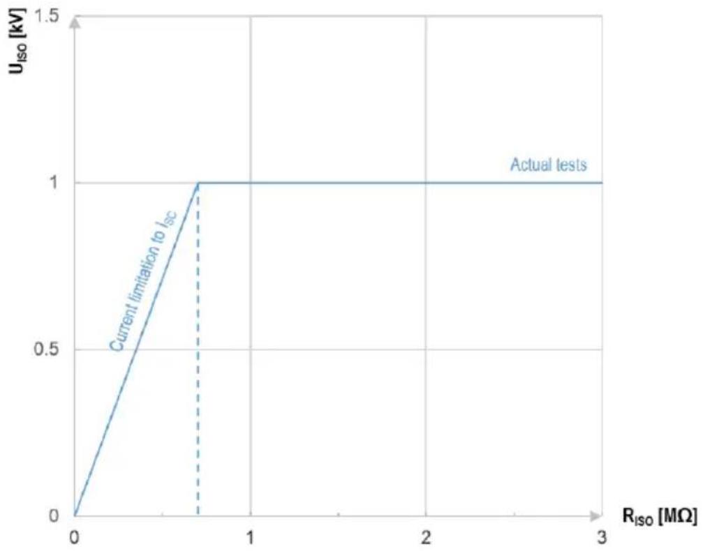
The meter measures the insulation resistance by applying to tested resistance R_ISO the U_ISO test voltage and measuring current I flowing through it, which is controlled from + terminal side. In calculating the value of insulation resistance, the meter applies the technical method of resistance measurement ( R_ISO=U_ISO/I ).
Inverter output current I_sc is 1 mA. Activation of the current limit is indicated by a continuous beep. The measurement result is correct, but on the test terminals the voltage is lower than the set voltage. The current limitation occurs in the first phase of the measurement due to charging the capacitance of the tested object
line
| R_iso [MΩ] | U_iso [kV] | | ---------- | ---------- | | 0 | 0 | | 0.5 | 1 | | 3 | 1 |The actual test voltage U_ISO as a function of the measured insulation resistance R_ISO (for maximum test voltage)
11 Manufacturer
The manufacturer of the device and provider of guarantee and post-guarantee service:
SONEL S.A.
Wokulskiego 11
58-100 Świdnica
Poland
tel. +48 74 884 10 53 (Customer Service)
e-mail: customerservice@sonel.com
web page: www.sonel.com

NOTE!
Service repairs must be performed only by the manufacturer.
NOTES

SONEL S.A.
Wokulskiego 11
58-100 Świdnica
Poland
Customer Service
tel. +48 74 884 10 53
e-mail: customerservice@sonel.com
- User manual
- PAT-95 · PAT-96
- CE
- Portable appliance tester
- CONTENTS
- General information....4
- Quick start 8
- Interface....9
- Data transmission....10
- Power supply....12
- Cleaning and maintenance ....15
- Storage....15
- Dismantling and utilisation....15
- Technical data....16
- Manufacturer 27
- General information
- Safety symbols
- Behaviour of signalling LEDs
- Safety
- WARNING
- Do not touch the tested device during measurements.
- NOTE!
- General characteristics
- Compliance with standards
- Quick start
- Additional information displayed by the meter
- Interface
- Data transmission
- Set of accessories to connect the meter to a PC
- Data transmission through USB port
- Fuse replacement
- Power supply
- Battery power
- Charging rechargeable battery
- Power supply from mains
- General principles regarding using Ni-MH rechargeable batteries
- Cleaning and maintenance
- Storage
- Dismantling and utilisation
- Technical data
- Basic data
- Measurement of network parameters
- Measurement of PE resistance
- Measurement of resistance of protective conductor I = 10 A (only Protection Class I)
- Measurement of resistance of protective conductor I = 25 A (only Protection Class I)
- Measurement of insulation resistance
- Measurement of insulation resistance using test voltage of 100 V
- Measurement of insulation resistance using test voltage of 250 V
- Measurement of insulation resistance using test voltage of 1000 V
- Measurement of leakage current
- Substitute leakage current
- PE leakage current
- Differential leakage current
- PE leakage current and differential current – clamp measurement
- Touch leakage current
- Testing RCDs / PRCDs
- Measurement of RCD / PRCD parameters
- Measurement of RCD / PRCD trip current I_A for sine differential current
- Measurement of RCD / PRCD trip current I_A for unidirectional pulsed sine differential current
- Functional test
- Measurement of S power
- Measurement of P power
- Measurement of Q power
- Power factor PF
- Measurement of voltage THD
- Measurement of current THD
- Cosφ measurement
- Current consumption during power measurement
- Current consumption measurement with clamp during power measurement
- Voltage measurement in test socket
- PAT-96 | Measurement of welding machine voltage without load
- Measurement of U_RMS voltage
- Measurement of U_P voltage (DC and AC_peak )
- Measurement of U_0 voltage
- Operating data
- Bluetooth specification
- Additional data
- Additional uncertainties according to EN IEC 61557-2 (RISO)
- Inverter characteristics
- Manufacturer
Brand : Sonel
Model : PAT-95
Category : Meter