PAT-2 - Meter Sonel - Free user manual and instructions
Find the device manual for free PAT-2 Sonel in PDF.


| Product Type | Portable Appliance Tester (PAT) |
| Model | PAT-2 |
| Dimensions | 200 mm x 150 mm x 74 mm |
| Weight | Approximately 1.40 kg |
| Power Supply | Mains 195 V…265 V AC, 50/60 Hz; internal NiMH 7.2V battery pack |
| Measurement Functions | PE conductor resistance (200 mA or 10 A), insulation resistance (250 V/500 V), substitute leakage current, differential leakage current, touch leakage current, PRCD trip time |
| Autotest Modes | Class I, Class II, IEC cable testing with automatic sequence |
| Display | Segment LCD with backlight |
| Memory | 10 banks, 99 cells each (dynamic allocation) |
| Data Transfer | USB 2.0; optional WiFi (for printing) |
| Printing | Label printing with Brother P750W printer (WiFi) |
| Protection Class | Double insulation (EN 61010-1), measurement category CAT II 300 V |
| Ingress Protection | IP40 |
| Operating Temperature | 0°C to +50°C |
| Storage Temperature | -20°C to +70°C |
| Humidity | 20% to 80% RH |
| Fuses | Two 5x20 mm 16 A Littelfuse (user-replaceable) |
| Battery Charging | Quick charge approx. 4 hours (tester off) or background charge (tester on) |
| Maintenance | Clean with soft damp cloth; do not use solvents; grease probe if stored; clean test leads |
| Standards Compliance | EN 50678, EN 50699, EMC EN 61326-1 |
| Manufacturer | SONEL S.A., Poland |
Frequently Asked Questions - PAT-2 Sonel
User questions about PAT-2 Sonel
0 question about this device. Answer the ones you know or ask your own.
Ask a new question about this device
Download the instructions for your Meter in PDF format for free! Find your manual PAT-2 - Sonel and take your electronic device back in hand. On this page are published all the documents necessary for the use of your device. PAT-2 by Sonel.
USER MANUAL PAT-2 Sonel
USER MANUAL
PORTABLE APPLIANCE TESTERS
PAT-2 • PAT-2E • PAT-10
USER MANUAL
PORTABLE APPLIANCE TESTERS PAT-2 • PAT-2E • PAT-10
CE
SONEL S.A.
Wokulskiego 11
58-100 Świdnica
Poland
Version 2.01 05.07.2023
The PAT-2/2E/10 testers are a modern, high quality, easy to use and safe measuring devices. Please acquaint yourself with the present manual in order to avoid measuring errors and prevent possible problems related to operation of the testers.
TABLE OF CONTENTS
1 Safety 5
2 Switching on and activating screen backlit 6
2.1.1 The first startup....7
2.1.2 Additional information displayed by the tester 8
3 Tester configuration .... 10
4 Measurements....19
4.1 Introduction 19
4.2 Manual tests.... 20
4.2.1 Preliminary test – visual inspection 21
4.2.2 Measurement of PE protective conductor resistance - R_PE 23
4.2.3 Measurement of insulation resistance - R_ISO 25
4.2.4 Measurement of substitute leakage current - I SUB 28
4.2.5 Measurement of differential leakage current - I △ 31
4.2.6 Measurement of touch leakage current – I T 33
4.3 AUTO mode tests - Class I 36
4.4 AUTO mode tests – Class II.... 42
4.5 Testing extension cords and IEC (power supply) cables 48
4.6 Measurement of portable residual current device trip time – PRCD 54
4.7 Compensation of the test lead's resistance (auto-zeroing) 59
5 Memory of measurement results....61
5.1 Storing the measurement results in the memory 61
5.2 Browsing memory data 63
5.3 Deleting memory data....64
5.3.1 Deleting cel data....64
5.3.2 Deleting bank data....66
5.3.3 Deleting the entire memory data 67
6 Label printing 69
6.1.1 Printer configuration....69
6.1.2 Printing after measurement....72
6.1.3 Printing from memory....72
6.1.4 Printing automatically when saving to memory....72
6.1.5 Label types 73
6.1.6 Printout data configuration with PC software....74
6.1.7 Placing the printer inside a carrying case....75
7 Data transmission....76
7.1 Accessories required to connect the tester to PC 76
7.2 Data transmission and tester configuration via USB port.... 76
8 Firmware update....77
9 Power supply of the tester....77
9.1 Monitoring the power supply 77
9.2 Charging the rechargeable battery pack 78
9.3 General principles of using Ni-MH batteries....79
10 Replacing fuses.... 79
11 Cleaning and maintenance....80
12 Storage 80
13 Dismantling and disposal.... 80
14 Technical data....81
14.1 Basic data....81
14.2 Other technical data 85
15 Manufacturer 86
1 Safety
The PAT-2, PAT-2E and PAT-10 testers are designed for performing check tests on electrical equipment, providing measurement results which determine the safety status of tested devices. Therefore, in order to provide conditions for correct operation and the correctness of the obtained results, the following recommendations must be applied:
- Before you commence operating the tester, acquaint yourself thoroughly with the present manual and observe the safety regulations and specifications determined by the manufacturer.
- Any application that differs from those specified in the present manual may result in a damage to the device and constitute a source of danger for the user.
- PAT testers must be operated only by appropriately qualified personnel. Operating the tester by unauthorized personnel may result in damage to the device and constitute a source of danger for the user.
- The instruments must not be used with installations or equipment situated in dangerous
- environments, e.g. where fire or explosion hazards exist.
- It is forbidden to operate the following:
⇒ A damaged tester which is completely or partially out of order,
⇒ A tester with damaged test leads insulation,
A tester stored for an excessive period of time in disadvantageous conditions (e.g. excessive humidity). If the tester has been transferred from a cool to a warm environment with a high level of relative humidity, do not start measurements until the tester is warmed up to the ambient temperature (approximately 30 minutes).
- The tester may be powered only from grounded mains sockets. The tester can't be powered from other sources than those mentioned in this manual.
- Before starting any measurement, make sure the test leads are connected to the proper test sockets.
- Do not touch the tested device during measurements.
- Test sockets and the socket for testing IEC cables are protected against improper connection to the voltage up to 300V AC for 60 seconds.
• Repairs may be carried out only by an authorised service point.
- Using this manual does not exclude the need to comply with occupational health and safety regulations and with other relevant fire regulations required during the performance of a particular type of work. Before starting the work with the device in special environments, e.g. potentially fire-risk/explosive environment, it is necessary to consult it with the person responsible for health and safety.
NOTE!
Use only original accessories (both standard and additional) designed for your tester, that are listed in 'Accessories' section. Using other accessories may cause damage to the measuring socket and can introduce additional measurement uncertainties.
Note:
Manufacturer reserves the right to apply changes in the appearance, accessories and technical parameters of the testers. Due to continuous development of the testers' software, the actual appearance of the display, in case of some of the functions, may slightly differ from the display presented in this operating manual.
Note:
An attempt to install drivers in 64-bit Windows 8 may result in displaying 'Installation failed' message.
Cause: Windows 8 by default blocks drivers without a digital signature.
Solution: Disable the driver signature enforcement in Windows.
2 Switching on and activating screen backlit

Turn on the tester with button.


Short press button to turn the screen backlight on; press the button again to turn the backlight off. When the tester is connected to the mains it automatically turns on the screen back-lit upon start up.

Switch off the meter by pressing and
and holding button for approx. 2 seconds.
Emergency situations
Pressing button for approx. 7 seconds will turn off and on (reset) the tester. Mains power supply must be disconnected while resetting.
After switching on, the tester displays the firmware version on screen - FXXX (where 'XXX' is the firmware number). Then it performs a self-test, during which the test screen is displayed along with the progress bar:
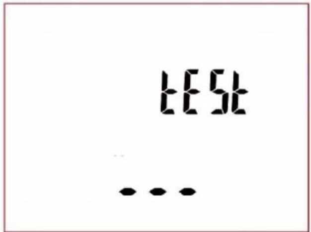
- measurement of the voltage in the power supply socket, i.e. the voltage between L and N of power supply to the tester,
• measurement of mains frequency,
• measuring the voltage between N and PE in the power supply socket,
- indicates swapped L and N terminals (icon on the screen).
Upon completing above self-check procedure, when everything is correct, the tester goes to the screen of the function that was on before the tester was switched off.
When the tester that is connected to mains, is switched off, it stays in a battery charging mode. In order to completely switch off the device, the mains plug must be disconnected and the tester must be switched off (see more in chapter 9 of this manual).
2.1.1 The first startup
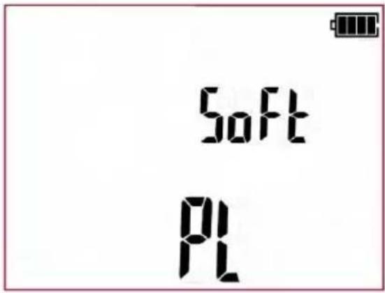
The firmware selection window is display upon the first start-up of the tester. The selection of the firmware version is a one-time exercise and it is remembered until resetting the tester to the factory settings. The versions may differ in measurement and printout settings. Standard available options are:
- PL – version for users in Poland,
- En – English version.
①

Use ↑ and ↓ buttons to select the version of the tester's interface (Software).
②

Press ENTER button to save selection.
2.1.2 Additional information displayed by the tester
Information that are or can be displayed during operation of the tester (in all measurement functions, configuration screens and others):
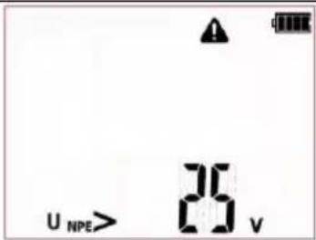 + audible signal + LED diodes flashing red + audible signal + LED diodes flashing red | Voltage UN-PE>25 V or lack of PE continuity, measurements are blocked. | |
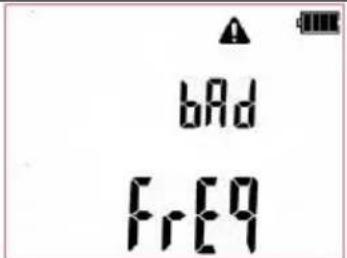 + audible signal + LED diodes flashing red + audible signal + LED diodes flashing red | Mains frequency is incorrect, measurements are blocked. (Bad frequency) | |
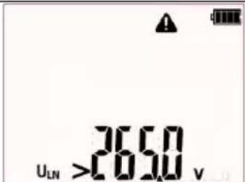 + audible signal + LED diodes flashing red + audible signal + LED diodes flashing red | Mains voltage >265 V, measurements are blocked. | |
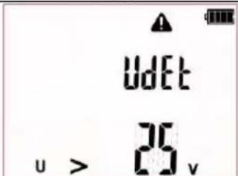 + audible signal + LED diodes flashing red + audible signal + LED diodes flashing red | Voltage on the test sockets >25 V, measurements are blocked. Disconnect the tested device with caution. | |
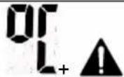 | The allowable inside temperature of the tester has been exceeded. Wait until the temperature drops (symbol disappears) and start measurements again. | |
| [1YWT]Symbol: (washing) | Connect mains power supply to run the test. | |
| [1WAG8]Symbol: | Mains power supply connected, power supply polarity is correct. | |
Symbol:  | Incorrect polarity of power supply, swapped L and N in the power supply socket of the tester. PAT automatically swaps L and N in the tester's test socket, and measurements are possible. | |
 | In order to properly perform the measurement, connect the measurement probe to the tested device. | |
| Refer to user manual. | ||
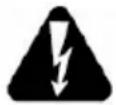 | In selected measurement function (or autotest with subsequent tests in it) after commencing measurement a dangerous voltage, from following source, is present: mains - the device under test will turn on, or a voltage generated during insulation resistance test (eg. 500V). | |
| ErrX | An error has been detected. Contact authorized service point. 'X' refers to an error code. | |
| turn on Prcd | Turn on the tested Portable Residual Current Device. | |
The tester can also display a number of other notifications, which are assigned to the different functions of the tester and have been described further in this manual.
3 Tester configuration
The tester configuration can also be performed using PC software.
①
Turn on the tester by pressing and keeping SET/SEL button pressed.
②
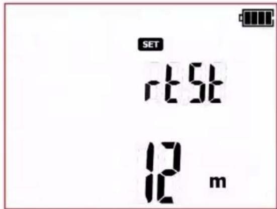
When the rtSt (re test) screen is displayed use ↑ and ↓ buttons to set the retest time (in months). Based on this information the tester will calculate the retest time that will show up on the printout. Select oFF to switch off this function.
③

Use and → to enter the autotest configuration screen: Atst.
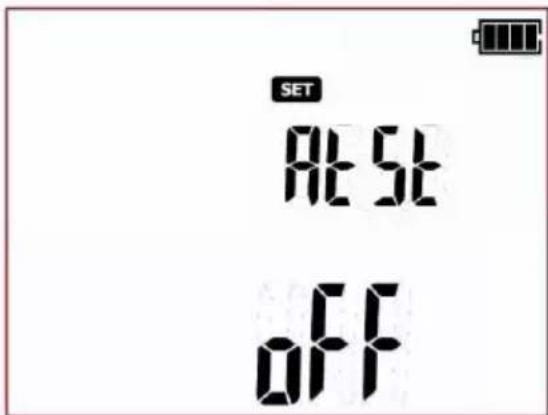

When Atst (Autotest) screen is displayed use ↑ and ↓ to turn the tests to be performed automatically: on (04 AUTO-TEST) or off (off
④

Use and → buttons to enter the screen with audio message settings: bEEP.
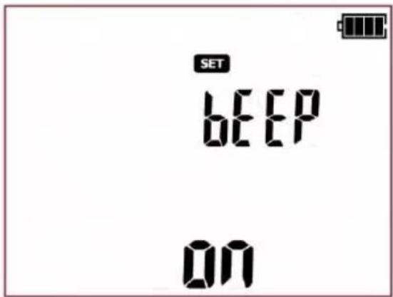
When bEEP screen is displayed use ↑ and ↓ to turn the audio messages ON (or OFF () off
⑤

Press and → to switch to auto off setting screen (Auto-off): AoFF
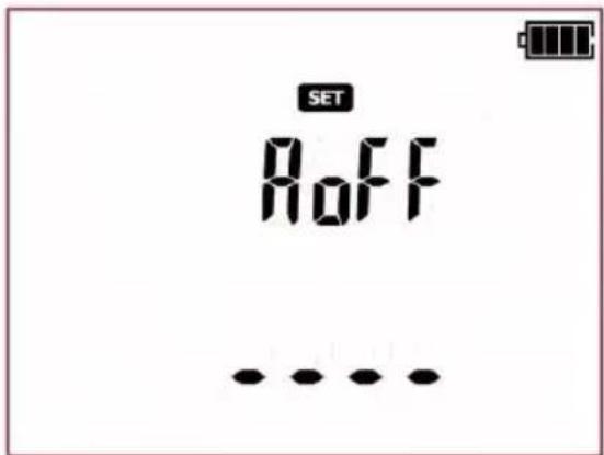
Use and to set the time period after which the tester will turn off automatically (Auto-off): 300 s, 600 s, 900 s or none (dashes - Auto-OFF is disabled). This function turns off the unused tester automatically after the certain (set by user) period of time.
⑥
Use and → buttons to enter the screen for activating WiFi wireless communication – (Radio Function): rF.
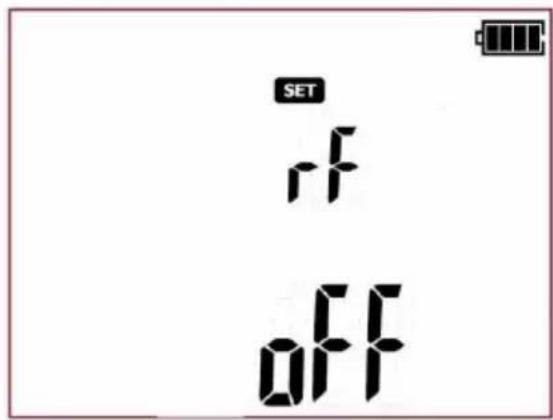

When rF screen is displayed use ↑ and ↓ to set the wireless connection: on (Off icon) or off (Off
⑦

Use and → buttons to enter the screen with report printing settings - (Print): Prnt.
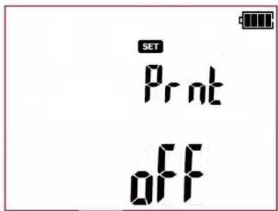
Use and buttons to set the report printing mode: standard report ( ), doll report ( ) not printing disabled ( ). off NOTE: The printing function will work only when the wireless communication function 'rF' is activated, and the connection with the printer is configured properly ( Prnt Conf).
⑧

Use and → to enter the screen with auto print mode settings after saving measurement results to memory - (Auto-Print): APrn.
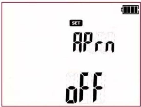
Use ↑ and ↓ to turn the auto print mode: on ( ) or off ( ) off
NOTE: The auto print mode will work only when the wireless communication function 'rF' is activated, and the connection with the printer Prnt is configured properly.
⑨
Use and → to enter the printer connection settings screen - (Printer configuration): Prnt Conf
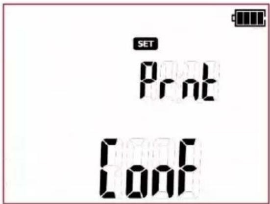

Press ENTER to go to the code entry screen (codE) that allows to establish the connection (These are the last four digits of the printer's serial number). Detailed configuration description is presented in section 6.1.1 of this manual.
10

Use and → to enter the screen where time and date can be set - (Date): DAtE
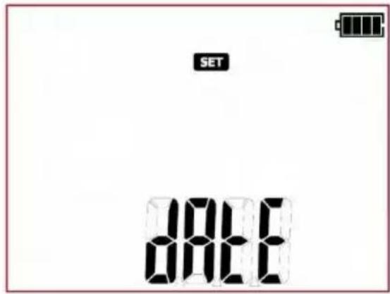

Press ENTER to enter the date setting mode (date format is DD/MM/RRRR):
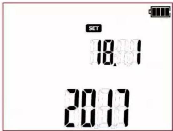
When in the date setting mode, the digit representing a day is flashing. Use ↑ and ↓ to set the correct day number.

Use and to go to the month and the year selection and set these numbers in the same way as the day.
11

When the date is set press ENTER to save changes and move to 24h time mode settings.
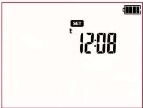


When the clock screen is displayed, the hour digit is flashing. Use ↑ and ↓ to set the proper value.


Use and to go to minutes settings and set the proper value in the same manner.

Press ENTER to save changes and return to the SET menu.
12


Use and to go to the screen for selecting the mains type from which the meter is powered: tYPE.
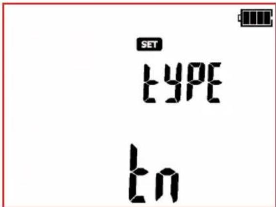


Use and to set the mains type: TN (tn) or IT (it).

Press ENTER to save changes and return to the SET menu.
13
Use and → to enter the screen for setting nominal network voltage powering the tester - (Unominal): Un
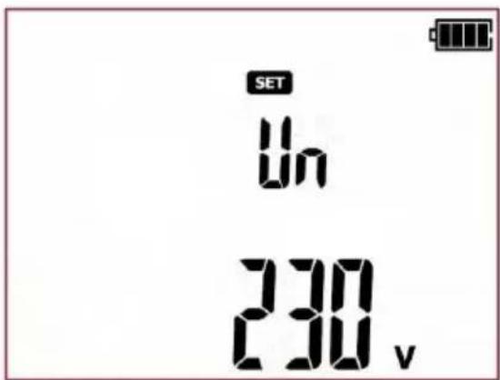
When the Un screen is displayed use ↑ and ↓ to set the nominal mains voltage value: 220 V, 230 V or 240 V.
14
Use and → to enter the screen with the mains frequency selection - (Frequency): Fr
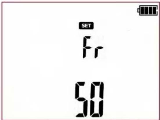
When the Fr screen is displayed use ↑ and ↓ to set the nominal mains frequency value: 50 Hz or 60 Hz.
15

Use and to enter the screen where the L-N resistance test can be switched on/off before the visual test - (Resistance L-N): r Ln ( R_L-N )
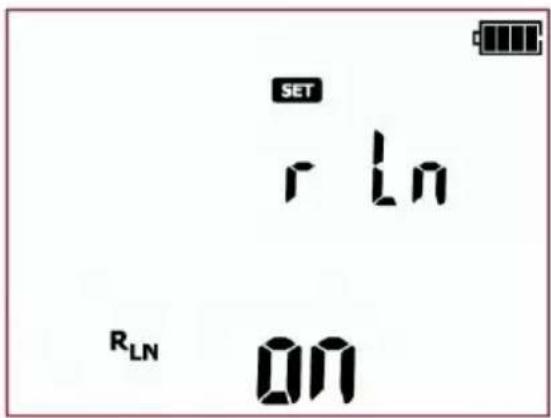

When the r Ln screen is displayed use ↑ and ↓ to turn: on ( ) or off ( ) off
16

Use and to enter the screen that allows to select the tester's response when the L and N are swapped in the polarity test of IEC cord: IEC
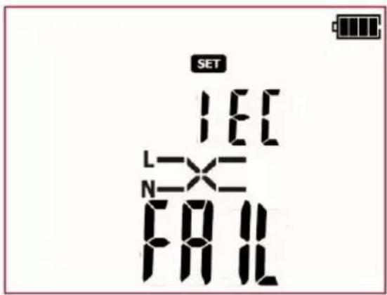

When the IEC screen is displayed use and to set the outcome result for swapped L and N: Negative test result (FAIL) or set the tester to allow swapped L and N lines (PASS).
17

Use and → to go to factory reset screen – (Factory settings): FAct SEtt
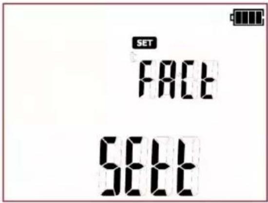

Press Enter to go to the reset confirmation screen of the tester settings, the ConF message is displayed. Press ENTER again to reset the tester to default factory settings.
18

Use and → buttons to enter the screen with firmware update: UPdt.
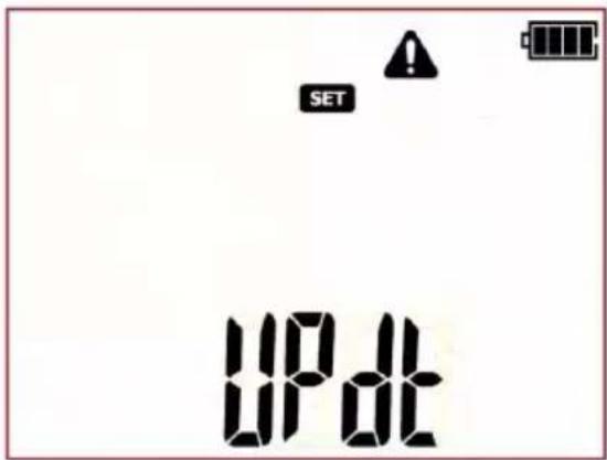

Press ENTER to enter the update mode. The update process is described in section 8.
After changing the parameters, you may exit SETUP menu:
Press and hold ENTER button for approx. 2 s to memorize settings (not applicable for Update screen) or use ESC button (2s) to go to the measurement screen without confirming the changes.
4 Measurements
Note:
The test parameters' settings (times, limits, others) presented in this manual are exemplary, and may differ from the ones pre-set in the tester.
Some tests require mains power supply, and will not run until the tester is connected to mains (plug symbol is flashing). Connect the tester to mains power supply to run the test.

During the measurement the tested appliance must be switched on.
4.1 Introduction
Beyond all doubt, safe use of machinery and equipment is the responsibility of the owner (company owner, home user), therefore, to state that the equipment is safe, regular checks and tests should be performed, based on the approved standards, appliances' user manuals. Tested appliances labelled as out of order, or the ones with expired check-up dates, should be immediately withdrawn from use. It is forbidden to use damaged or faulty work tools and safety equipment.
Note that not only power tools should be tested. Extension cords, office and kitchen equipment or production machines are equally prone to damage. These items are frequently exposed to damage, especially when used at construction sites or in other severe conditions. Apart from mechanical impacts, damage may also be caused by e.g. high external temperature or internal overheating due to high current flow. Extreme temperatures are the major cause of deterioration. Therefore extension or power supply cord should be frequently tested.
Very important part of the test is the visual examination. After the visual check is done, electrical safety tests are to be performed. It is for the user (owner) to decide about test intervals. Frequent testing of equipment improves their operating safety.
Electrical devices and power tools are divided into three protection classes – depending on the method employed in designing power tools to ensure their electric shock protection:
Class I - in addition to the basic insulation, all metallic parts are connected with PE protection wire in such a manner that, in the event of insulation damage, they may not become live.
Class II – power tools without the PE protection wire, but double, or reinforced insulation is required in addition to the basic one. With proper insulation, the enclosure can also be made out of metal.
Class III - power tools of this class are supplied by circuits with very low voltage, the value of which may not exceed:
- 50V(AC) or 120V(DC) - in normal conditions;
- 25V(AC) or 60V(DC) - in case of more hazardous conditions;
- 12V(AC) or 30V(DC) - in case of special hazards.
PAT series testers allow to perform tests in single or in auto-test mode - a testing procedure consisting of several, different test types that are subsequently carried out one after another. Manual tests
are available under button, auto tests are available under:
- measuring procedure for Class I appliances.
-
- measuring procedure for Class II appliances (can apply for the majority of the Class III appliances).
- IEC - measurement procedure for IEC power cords, extension cords, and oter power cords.
Additionally the tester allows to measure parameters of portable residual-current devices, PRCD (stand alone portable RCDs or the ones built into extension cords, switchgears, etc.). This function is
available under button (only PAT-2E and PAT-10).
Measurement settings can be done through SET menu or by using PC software.
4.2 Manual tests
In the manual mode, all the test types supported by the tester can be performed. Press

button (LED is on) to switch between all available tests (except for PRCD and IEC
cord polarization tests – these are available under separate buttons Press the button repeatedly to change the selected test type. The selected test is indicated by a corresponding icon displayed on screen. Available tests are, respectively:
- preliminary test – visual inspection,
• R _ref 200 mA measurement of protective conductor resistance with 200mA test current, - R_PE 10A - measurement of protective conductor resistance with 10A test current (only PAT-10),
- RISO 250V - measurement of insulation resistance with 250V test voltage,
- R_ISO 500V - measurement of insulation resistance with 500V test voltage,
- I _SUB - measurement of substitute leakage current,
- I_ -measurement of differential leakage current (only PAT-2E and PAT-10),
- I _T - measurement of touch leakage current (only PAT-2E and PAT-10).
During the measurement the tested appliance must be switched on.
Upon completing each measurement, its parameters, date and test time duration can be viewed:

press and → to browse the components of measurement results data.
4.2.1 Preliminary test – visual inspection
Visual inspection of the tested appliance is the first step to take on the way to proper evaluation of its technical condition. The inspection is made with the use of simple tools. The scope of the inspection is often determined by the type of the device under test. This inspection aims to make a visual assessment of the technical condition of the device under test. Additionally the tester can measure the resistance of L-N circuit and display the result, which helps the user to make a decision (note - the result of this measurement is neither stored, nor automatically evaluated by the tester). The measurement of the L-N circuit can be switched off on the SET main menu.
①
Press MANUAL to enter the screen for preliminary test - 100 will appear on screen.
②
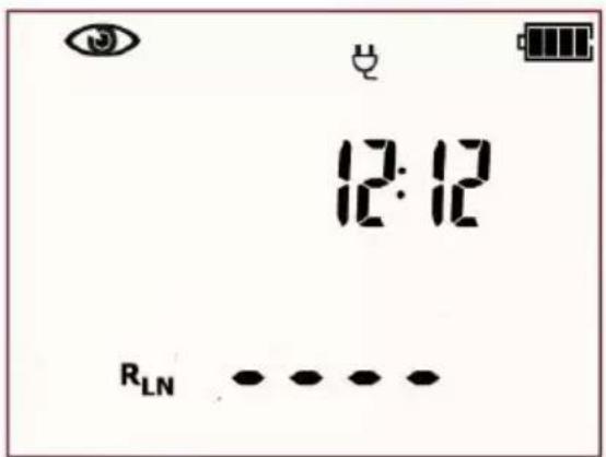
The tester is now in the preliminary test-visual inspection mode. Additionally the current time is displayed on the screen.
③
If the measurement of the L-N circuit resistance is selected, connect the test leads as shown in the picture below:
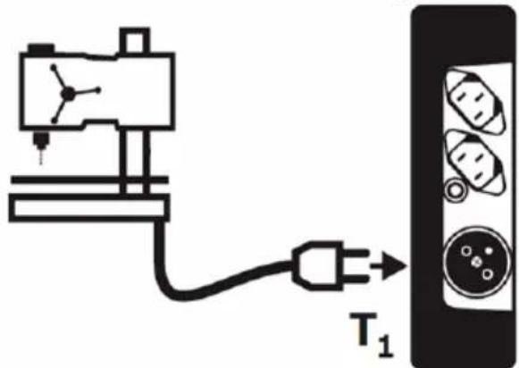
R_L-N measurement refers to resistive objects, in the case of inductive objects, the result may be subject to additional error
PAT-2 • PAT-2E • PAT-10 – USER MANUAL
④

Press START/STOP. Preliminary test mode is on and additionally the measurement of L-N circuit resistance will be conducted (if activated in the SET menu).
⑤
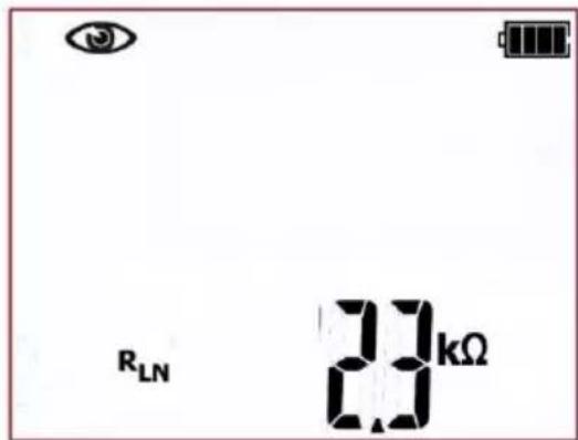
The tester is waiting for the evaluation of the device after completing visual inspection. If the measurement of the L-N circuit resistance is selected, tester will also display the result of R_LN measurement. If it's not selected, then dashes will be displayed in the main screen area „----”.
⑥
The inspection of the tested device must be carried out.
Among others, examine the following: PE cable and power cables of the tested device, mains plug (against cracks and burnouts), cable fittings and terminations, housing, air vents, identification plates, covers, commutators and brushes, windings, bearings, mechanical systems and other elements that affect proper operation of the device and safety of the user.
⑦

Press PASS (V) or FAIL button (X) to evaluate the tested device's condition: (V) PASS means positive visual examination result, (X) FAIL – negative visual examination result, irregularities were found in the device.
⑧
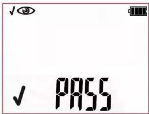
Positive visual inspection result. Green LEDs of PASS indication are on.
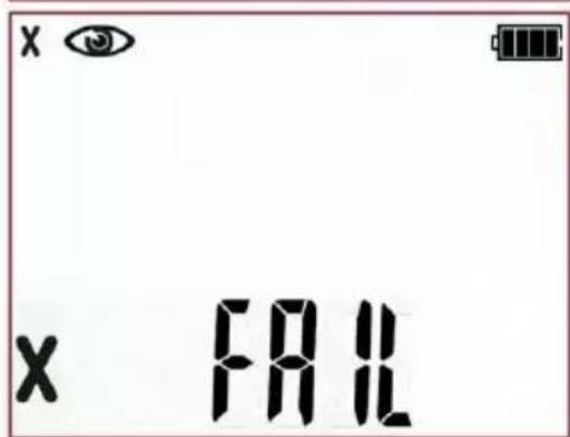
Negative visual inspection result. Red LEDs of FAIL indication are on.
The result is displayed on screen until ESC button is pressed, another test is run by pressing START button, measurement mode is changed, settings mode is activated, tester is switched off or the test result is stored in the memory.
More messages displayed by the tester are described in section 2.1.2 of this manual.
4.2.2 Measurement of PE protective conductor resistance - R_PE
The PE conductor is tested in the 1st protection class devices. The measurement is taken between the protective contact of the plug (or connection point in case of devices connected permanently) and metallic parts of the enclosure connected with the PE wire.
Resistance of the PE conductor is a sum of several components:
- resistance of the power core,
- resistance of the connectors,
- resistance of the extension cord (if exists).
This test is performed to evaluate the technical condition of PE conductor and PE connection with the tested device. The measurement can be performed with 200mA or 10A (only PAT-10) test current. Measuring with 10A requires connecting the tester to mains.
①
Press MANUAL button to go to PE resistance measurement – R on 200 mA will be displayed for 200mA current test or
RPE 10A ) for 10A (after pressing MANUAL button again). The measurement procedure is the same for both current values.
②
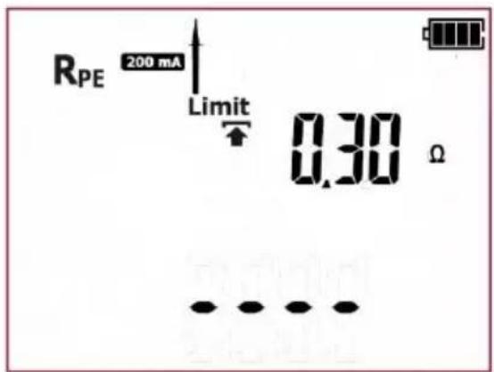
The tester is in PE conductor resistance measurement mode.
③

Press SET/SEL button to go to the settings of measurement parameters.
④

Press ↑ and ↓ to set the upper limit of RPE resistance.
⑤

Press and to go to the test time duration settings.
⑥
Use ↑ and ↓ to set the test time duration value.
⑦

or
Press ENTER to confirm settings or press ESC to exit without saving the changes.
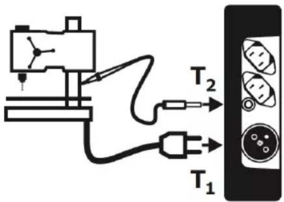
Connect test leads according to the drawing.
⑧
⑨

Press START/STOP to commence measurement of PE protective conductor resistance.
10
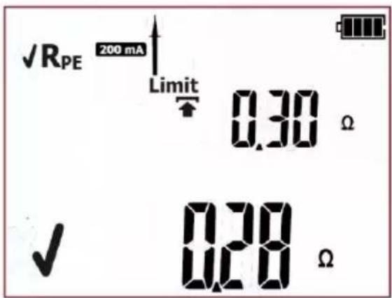
Correct result. The value of PE resistance is below the set limit. Green LEDs of PASS indication are on.
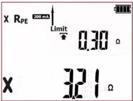
Incorrect result. The value of PE resistance is above the set limit. Red LEDs of FAIL indication are on.
The result is displayed on screen until ESC button is pressed, another test is run by pressing START/STOP button, measurement mode is changed, settings mode is activated or the test result is stored in the memory.
Additional information displayed by the tester
| RPE>19,99Ω | Measuring range is exceeded. |
More messages displayed by the tester are described in section 2.1.2 of this manual.
4.2.3 Measurement of insulation resistance - R_ISO
Proper insulation resistance is crucial for the operating safety of devices. It should be measured together with the power supply cord. According to the standards (among others: Polish, British, German), it should be measured with the test voltage of 500V and with the measuring current of 1mA.
The measuring time should be at least 60 seconds.
The test is done between shorted L-N wires and the exposed metallic parts of the enclosure. Not only the main components must be checked but also any bolts, terminals or other metallic parts. It may occur that a bolt, e.g. after mounting device holder, damages the insulation of the live conductor and becomes live.
In order to measure resistance of insulating parts, they can be wrapped (tested device or its parts) with an aluminum foil on the entire surface.
This test is performed to evaluate the condition of insulation of the tested device. R _ISO measurement can be performed with the test voltage of 250V (only PAT-2E and PAT-10) or 500V.
①
Press MANUAL button to go to insulation resistance measurement – Rason 250V will be displayed for 250V test voltage
measurement or Rsp 560V (after pressing MANUAL button again). The measurement procedure is the same for both voltage values.
②
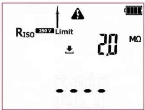
The tester is in insulation resistance measurement mode.
③
Press SET/SEL button to set the measurement parameters.
④
Use and to set the upper limit of R_ISO resistance.
⑤

Use and to go to the test time duration settings.
⑥
Use ↑ and ↓ to set the test time duration value.
⑦

or
Press ENTER to confirm settings or press ESC to exit without saving the changes.
Connect test leads according to the drawing :
⑧
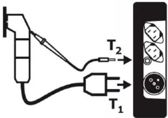
For Class I appliances, the previous R_PE test has to have positive result. The measurement is made between shorted L, N and PE. Connection diagram for Class I appliances (there is possibility, in most cases not required, to carry out the measurement with the test lead with probe connected to T_2 terminal socket):
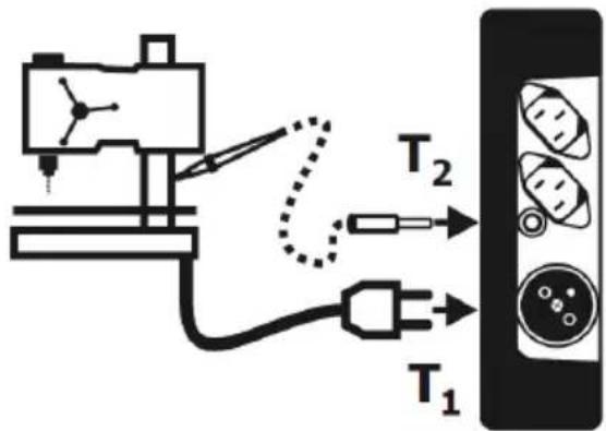
Connection diagram for Class II (III) appliances. The test lead with the probe must be connected to T_2 terminal socket. The measurement is made between shorted L and N, and the probe:
⑨

Press START/STOP to commence measurement of PE protective conductor resistance.
10
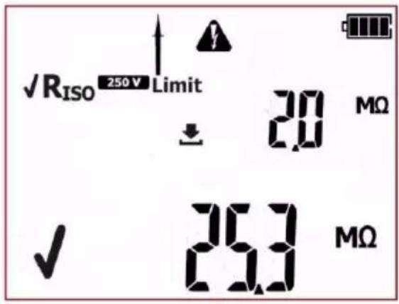
Correct result. The value of insulation resistance is above the set limit. Green LEDs of PASS indication are on.
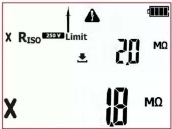
Incorrect result. The value of insulation resistance is below the set limit. Red LEDs of FAIL indication are on.
The result is displayed on screen until ESC button is pressed, another test is run by pressing START/STOP button, measurement mode is changed, settings mode is activated or the test result is stored in the memory.
Additional information displayed by the tester
| Riso > 99,9MΩ | Measuring range is exceeded. |
More messages displayed by the tester are described in section 2.1.2 of this manual.
Notes:
- Tested device must be turned on.
- Test circuit is electrically isolated from the mains and from mains' PE lead.
- Test result should be read only after displayed values are stabilized.
- After the measurement the tested object is automatically discharged.
4.2.4 Measurement of substitute leakage current - I_SUB
This test is performed to evaluate the condition of insulation of the tested device by determining the value of leakage current. Leakage current flows from live parts, through insulation, to earth. The leakage current includes: current flow through the insulation and capacitances in the device (among others from filtering or control systems). Leakage current affects operating safety and, sometimes, causes interference within the power grid.
Particular attention is required for testing devices that are operated in severe conditions, heavy dustiness or high humidity.
During the measurement of substitute leakage current the tester applies test voltage between shorted L and N of the device tested and PE, in case of class I devices, or probe in case of class II devices.
The measurement is done at the voltage between 25V and 50V, and the value of the measured current is scaled proportionally to the value that would occur at the nominal mains voltage supplying the device. The measuring circuit is galvanically separated from the grid and the from the PE wire.
For Class I appliances, the previous R_PE test has to have positive result.
①
Press MANUAL button to go to substitute leakage current measurement – Isub will be displayed.
②
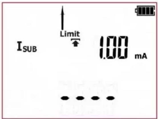
The tester is in substitute leakage current measurement mode.
③

Press SET/SEL button to set the measurement parameters.
④
Use ↑ and ↓ to set the upper limit of leakage current.
⑤
Use and to go to the test time duration settings.
⑥

Use ↑ and ↓ to set the test time duration value.
⑦

or
Press ENTER to confirm settings or press ESC to exit without saving the changes.
Connect test leads according to the drawing.

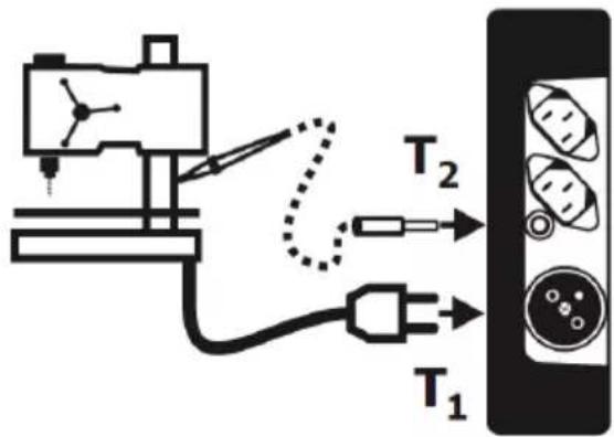
For Class I appliances, the previous R_PE test has to have positive result. As described above, the measurement is made between shorted L, N and PE. Connection diagram for Class I appliances (there is possibility, in most cases not required, to carry out the measurement with the test lead with probe connected to T_2 terminal socket):
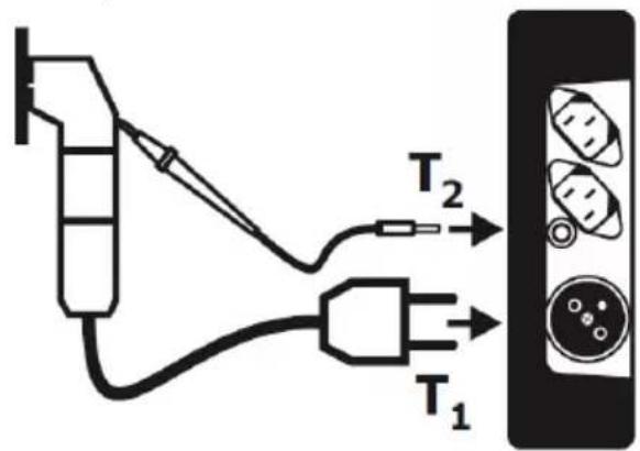
Connection diagram for Class II (III) appliances. The test lead with the probe must be connected to T_2 terminal socket. The measurement is made between shorted L and N, and the probe:


Press START/STOP to commence measurement of protective conductor resistance.

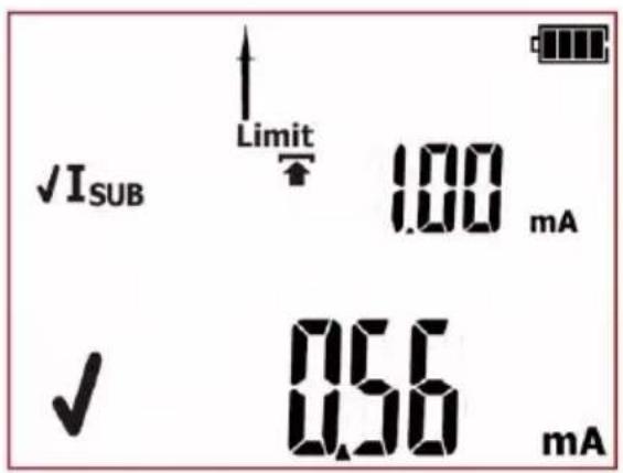
Correct result. The value of leakage current is below the set limit. Green LEDs of PASS indication are on.
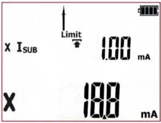
Incorrect result. The value of leakage current is above the set limit. Red LEDs of FAIL indication are on.
The result is displayed on screen until ESC button is pressed, another test is run by pressing START/STOP button, measurement mode is changed, settings mode is activated or the test result is stored in the memory.
Additional information displayed by the tester
| I_SUB>19,9mA | Measuring range is exceeded. |
More messages displayed by the tester are described in section 2.1.2 of this manual.
Notes:
- Tested device must be turned on.
- Test circuit is electrically isolated from the mains and from mains' PE lead.
- Test voltage is 25 V...50 V rms.
- I_SUB current is measured at <50 V voltage and its value is rescaled to the nominal mains voltage value set in the menu (see section 3). The resistance of the measuring circuit is 2kΩ.
4.2.5 Measurement of differential leakage current - I
Δ
This test is performed to evaluate the condition of insulation of the tested device by determining the value of leakage current. Leakage current flows from live parts, through insulation, to earth. The leakage current includes: current flow through the insulation and capacitances in the device (among others from filtering or control systems). Leakage current affects operating safety and, sometimes, causes interference within the power grid.
Particular attention is required for testing devices that are operated in severe conditions, heavy dustiness or high humidity.
Differential leakage current is measured as a difference between L current and N current, for all protection class devices. This measurement takes into account not only PE leakage current (for Class I devices), but also leakage currents caused by other earthed elements - e.g. water pipe. The measurement result is a sum of all leakages present in the device. This test can be performed only when the tester is connected to mains. During the measurement the tester automatically changes the polarity of the test socket and repeats the measurement. As a test result it displays the value of the higher leakage current.
①
Press MANUAL button to go to differential leakage current measurement – Icon will be displayed.
②
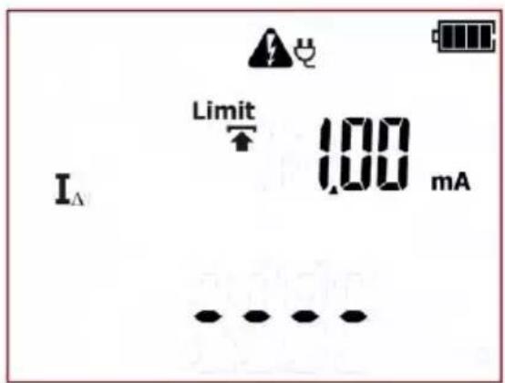
The tester is in differential leakage current measurement mode.
③

Press SET/SEL button to set the measurement parameters.
④

Use ↑ and ↓ to set the upper limit of leakage current.
⑤

Use and to go to the test time duration settings.
⑥

Use ↑ and ↓ to set the test time duration value.
⑦

or
Press ENTER to confirm settings or press ESC to exit without saving the changes.
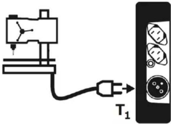
Connect test leads according to the drawing.

Differential leakage current is measured as a difference between L current and N current. This measurement takes into account not only PE leakage current, but also leakage currents caused by other earthed elements - e.g. water pipe. The disadvantage of this measurement is the presence of common current (supplied to the device through L line and returning via N line), that is influencing the accuracy of the measurement. Connection:


Press START/STOP to commence measurement of protective conductor resistance.

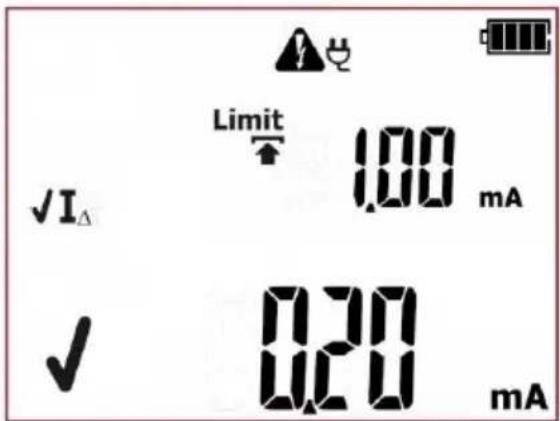
Correct result. The value of leakage current is below the set limit. Green LEDs of PASS indication are on.
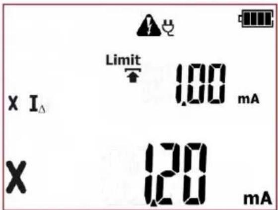
Incorrect result. The value of leakage current is above the set limit. Red LEDs of FAIL indication are on.
The result is displayed on screen until ESC button is pressed, another test is run by pressing START/STOP button, measurement mode is changed, settings mode is activated or the test result is stored in the memory.
Additional information displayed by the tester
I_>19,9mA
Measuring range is exceeded.
More messages displayed by the tester are described in section 2.1.2 of this manual.
Notes:
During the measurement in the test socket the mains voltage is present.
During the measurement the tester automatically changes the polarity of the test socket and repeats the measurement.
During the measurement of a faulty appliance, RCD switch may be triggered off..
- The tested device must be turned on.
- The result of measurement may be affected by the presence of external fields and by the current used by the device.
- When measuring devices which power consumption exceeds 10A, the measurement time is automatically limited to a maximum of 15s.
4.2.6 Measurement of touch leakage current – I
T
This test is performed to evaluate the technical condition of the tested device by determining the value of touch leakage current with the adjusted bandwidth of the measured current, that results from the measuring system used that simulates human perception and reaction. The internal probe resistance is 2kΩ. This test can be performed only when the tester is connected to mains. During the measurement the tester automatically changes the polarity of the test socket and repeats the measurement. As a test result it displays the value of the higher leakage current.
①

Press MANUAL button to go to touch leakage current measurement – Icon will be displayed.
②
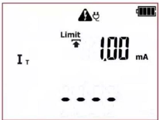
The tester is in touch leakage current measurement mode.
③

Press SET/SEL button to set the measurement parameters.
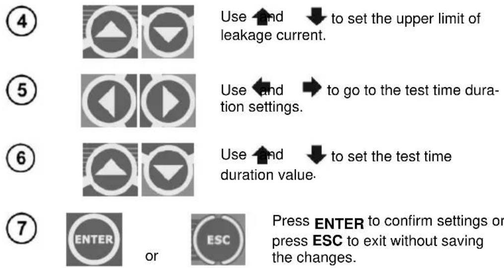
Use and ↓ to set the upper limit of leakage current.
Use and to go to the test time duration settings.
Use ↑ and ↓ to set the test time duration value.
Press ENTER to confirm settings or press ESC to exit without saving the changes.
⑧
Connect test leads according to the drawing.
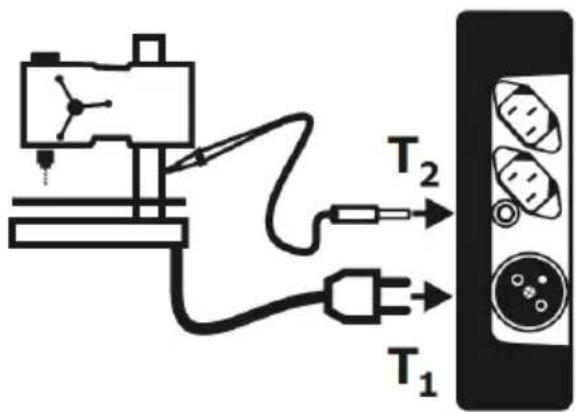
⑨

Press START/STOP button. The measurement of resistance of protective conductor will commence.
10
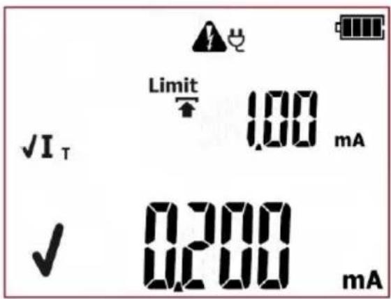
Correct result. The value of leakage current is below the set limit. Green LEDs of PASS indication are on.
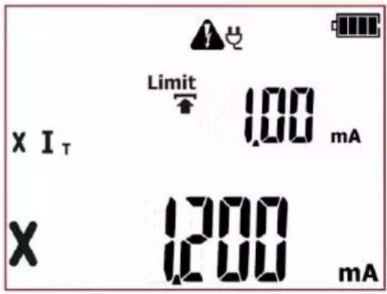
Incorrect result. The value of leakage current is above the set limit. Red LEDs of FAIL indication are on.
The result is displayed on screen until ESC button is pressed, another test is run by pressing START/STOP button, measurement mode is changed, settings mode is activated or the test result is stored in the memory.
Additional information displayed by the tester
I_T>3,999mA Measuring range is exceeded.
More messages displayed by the tester are described in section 2.1.2 of this manual.
Notes:
During the measurement in the test socket the mains voltage powering the tested device is present.
During the measurement the tester automatically changes the polarity of the test socket and repeats the measurement.
During the measurement of a faulty appliance, RCD switch may be triggered off.
- The tested device must be turned on.
- Ensure that the location of the tested device is isolated.
- The bandwidth of test current results from the measuring system with adjusted touch current which simulates human perception and reaction, in accordance with EN 60990: 2002. This is distinguished, among others, by that the internal probe resistance equals 2k .
4.3 AUTO mode tests – Class I
This test is performed to evaluate the technical condition of the tested devices belonging to the safety Class I equipment. The principles for carrying out each single test, and setting their parameters, are the same as for the measurements in the manual mode.

After passing visual examination check (press PASS button), when the AUTO-TEST (AUTO-TEST icon is displayed) mode is on, the tester will automatically run subsequent tests. The ongoing measurements can be stopped by pressing START/STOP button.
NOTE:
Some tests in autotest procedures require the tester to be powered from the mains. When it's not
connected the test sequence can't be initiated, mains plug icon: is flashing. In order to start the selected set of tests, the mains power supply must be connected.
PAT-2E and PAT-10 testers allow to run the tests from their batteries when the mains power supply is

disconnected. In order to do that, press and hold CL I button for 3 seconds. The tester will enter the battery powered measurement mode. If the measurement procedure included some tests requiring mains power supply (ie. I_, I_T ) they will be turned off. If the measurement of R PE with 10A test current has been selected, it will be switched into 200mA test current version. Limits and test time duration settings remain unchanged. After changing the measurement mode (selecting another autotest or manual test), the tester will return to default settings that require mains power supply.
①
Press CL I to go to testing procedure for

Class I appliances ( LED is on) – icons representing all subsequent tests will be displayed on screen. An exemplary procedure is shown below.
②
The tester is in autotest mode for Class I devices. Icons displayed on the left side represent all tests that will be performed. On the right side the current time is shown.
16
Use and to set the test time duration for insulation resistance measurement. Select "oFF" to switch off this test completely.
Parameters of each subsequent test are selected in the same manner.
17

or
Press ENTER to confirm settings or press ESC to exit without saving the changes.
18
The inspection of the tested device must be carried out.
Among others, examine the following: PE cable and power cables of the tested device, mains plug (against cracks and burnouts), cable fittings and terminations, housing, air vents, identification plates, covers, commutators and brushes, windings, bearings, mechanical systems and other elements that affect proper operation of the device and safety of the user.
19
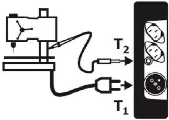
If the result of the visual inspection is positive, connect the tested device according to the diagram below (tested device should be turned on).
20

Press START/STOP button. The visual inspection mode is on.
21
natural_image
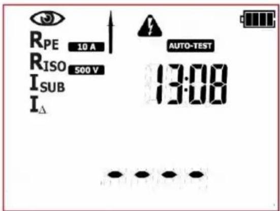
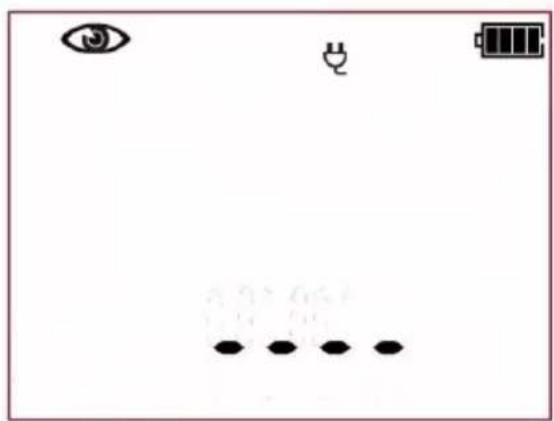
Simple diagram with eye, battery, and dot pattern (no text or symbols)The tester is waiting for the evaluation of the device after completing visual inspection. If the measurement of the L-N circuit resistance is selected, tester will also display the result of R_LN measurement. If it's not selected, then dashes will be displayed in the main screen area „----”.


Press PASS (V) or FAIL button (X) to evaluate the tested device's condition: PASS means positive visual examination result – if the AUTO-TEST mode is on, the tester will automatically run the sequence of tests. If the AUTO-TEST mode is off, commencing subsequent test will require pressing START/STOP button. FAIL – means negative visual examination result. Irregularities in the device have been found. Further measurements will not be conducted.

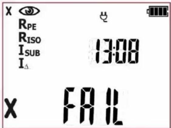
Negative visual inspection result, further measurements will not be conducted. Red LEDs of FAIL indication are on. On the right side of the screen the current time is shown.
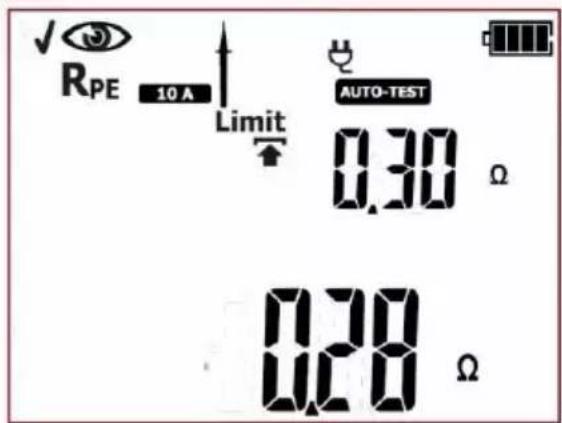
Positive visual inspection result. If the AUTO-TEST

the tester will automatically run the subsequent tests, which by default is: RPE. If the AUTO-TEST mode is off the tester will wait for the START/STOP button to be pressed.
24
Measurement of PE protective conductor has been completed. If the measurement result is negative, further measurements will not be conducted. In case of the positive test result:
If the AUTO-TEST mode is on, the tester will automatically run the subsequent test, which by default is: Riso. If the
AUTO-TEST mode is off the tester will wait for the START/STOP button to be pressed. At this stage it is possible to return to the previous test to repeat

25
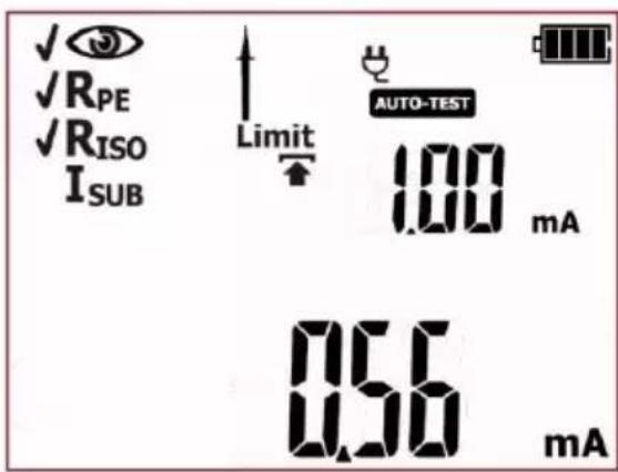
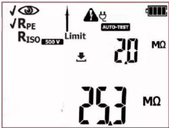
Measurement of insulation resistance has been completed. If the measurement result is negative, further measurements will not be conducted. In case of the positive test result: If the AUTO-TEST

on, the tester will automatically run the subsequent tests. If the AUTO-TEST mode is off the tester will wait for the START/STOP button to be pressed. At this stage it is possible to return to the previous test to repeat

it: press
26
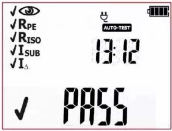
Positive test result for the tested device. The result of each single test of the sequence is positive. Green LEDs of PASS indication are on. On the right side of the screen the current time is shown.
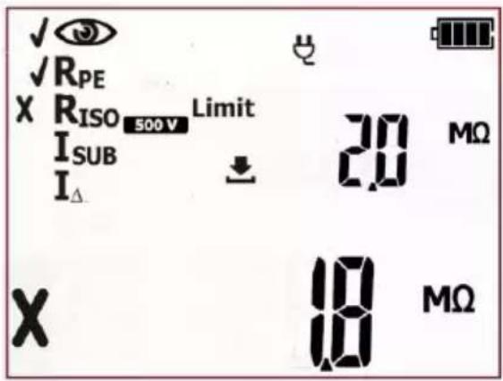
Negative test result for the tested device. One of the subsequent tests has ended with negative result - that result is displayed on screen (screen on the left, as an example, shows failed insulation resistance test). Red LEDs of FAIL indication are on.
The result is displayed on screen until ESC button is pressed, another test is run by pressing START/STOP button, measurement mode is changed, settings mode is activated or the test result is stored in the memory.
NOTE:
When a test result is incorrect and thus the entire auto test (FAIL), eg. caused by incorrect connection of a test probe, it is possible to return to the measurement that was conducted last and repeat it.

In order to do that press when the autotest summary is displayed on screen.
If the device under test, or its power cord, is equipped with portable residual current device (PRCD), its parameters shall also be checked. – see section 4.6 of this manual.
More messages displayed by the tester are described in section 2.1.2 of this manual.
4.4 AUTO mode tests – Class II
This test is performed to evaluate the technical condition of the tested devices belonging to the safety Class II equipment (and the majority of the devices in Class III). The principles for carrying out each single test, and setting their parameters, are the same as for the measurements in the manual mode.

After passing visual examination check (press PASS button), when the AUTO-TEST (AUTO-TEST icon is displayed) mode is on, the tester will automatically run subsequent tests. The ongoing measurements can be stopped by pressing START/STOP button.
NOTE:
Some tests in autotest procedures require the tester to be powered from the mains. When it's not
connected the test sequence can't be initiated, mains plug icon: is flashing. In order to start the selected set of tests, the mains power supply must be connected.
PAT-2E and PAT-10 testers allow to run the tests from their batteries when the mains power supply is

disconnected. In order to do that, press and hold CL II button for 3 seconds. The tester will enter the battery powered measurement mode. If the measurement procedure included some tests requiring mains power supply (eg. I , I _T ) they will be turned off. If the measurement of R PE with 10A test current has been selected, it will be switched into 200mA test current version. Limits and test time duration settings remain unchanged. After changing the measurement mode (selecting another autotest or manual test), the tester will return to default settings that require mains power supply.


Press CL II to go to testing procedure for

Class II appliances ( LED is on) - icons representing all subsequent tests will be displayed on screen. An exemplary procedure is shown below.

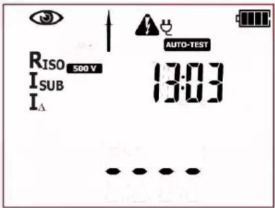
The tester is in autotest mode for Class II devices. Icons displayed on the left side represent all tests that will be performed. On the right side the current time is shown.
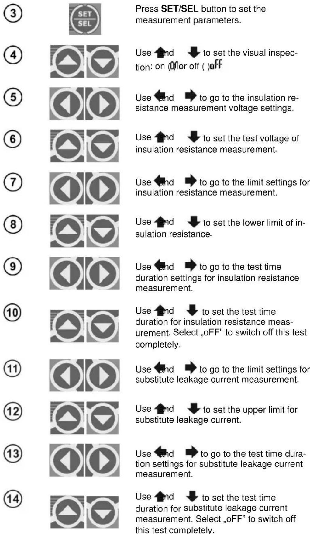
Parameters of each subsequent test are selected in the same manner.
15

or
Press ENTER to confirm settings or press ESC to exit without saving the changes.
16
The inspection of the tested device must be carried out.
Among others, examine the following: PE cable and power cables of the tested device, mains plug (against cracks and burnouts), cable fittings and terminations, housing, air vents, identification plates, covers, commutators and brushes, windings, bearings, mechanical systems and other elements that affect proper operation of the device and safety of the user.
17
If the result of the visual inspection is positive, connect the tested device according to the diagram below (the device should be turned on).
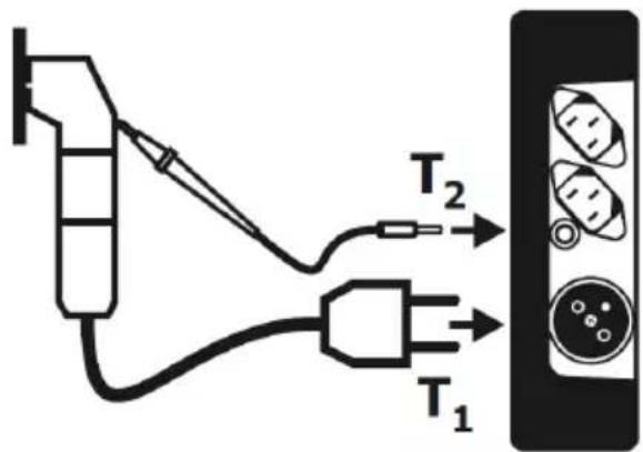
18

Press START/STOP button. The visual inspection mode is on.
19
natural_image
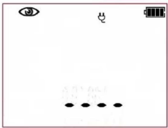
Simple diagram with eye, battery, and battery symbol above a grid of dots below (no text or labels)The tester is waiting for the evaluation of the device after completing visual inspection. If the measurement of the L-N circuit resistance is selected, tester will also display the result of R_LN measurement. If it's not selected, then dashes will be displayed in the main screen area „----”.
20

Press PASS (V) or FAIL button (X) to evaluate the tested device's condition: PASS means positive visual examination result – if the AUTO-TEST
AUTO-TEST, the tester
will automatically run the sequence of tests. If the AUTO-TEST mode is off, commencing subsequent test will require pressing START/STOP button. FAIL – means negative visual examination result. Irregularities in the device have been found. Further measurements will not be conducted.
21
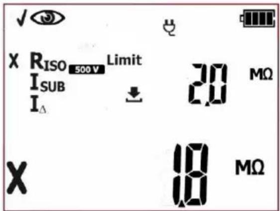
Negative visual inspection result, further measurements will not be conducted. Red LEDs of FAIL indication are on. On the right side of the screen the current time is shown.
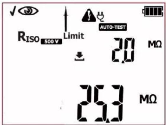
Positive visual inspection result. If the AUTO-TEST
AUTO-TEST
on, the tester will automatically run the subsequent tests, which by default is: RISO. If the AUTO-TEST mode is off the tester will wait for the START/STOP button to be pressed. At this stage it is possible to return to the previous test

to repeat it: press button.
22
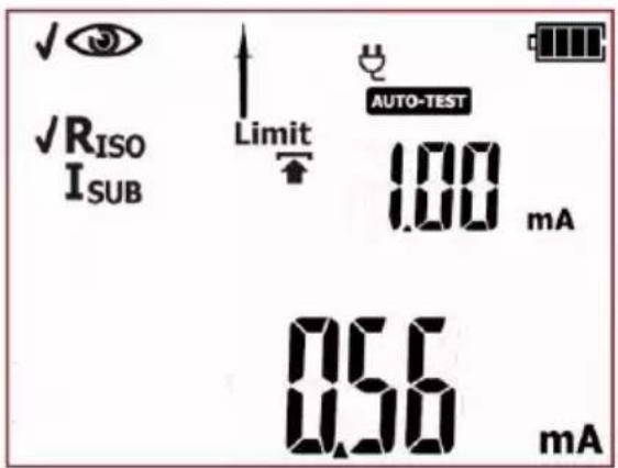
Measurement of R_ISO insulation resistance has been completed. If the measurement result is negative, further measurements will not be conducted. In case of the positive test result: If the AUTO-TEST
AUTO-TEST
on, the tester will automatically run the subsequent test, which by default is: Isub. If the AUTO-TEST mode is off the tester will wait for the START/STOP button to be pressed. At this stage it is possible to return to the previous test to repeat

23
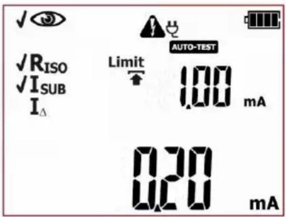
Measurement of substitute leakage current has been completed. If the measurement result is negative, further measurements will not be conducted. In case of the positive test result: If the AUTO-TEST
AUTO-TEST
on, the tester will automatically run the subsequent tests. If the AUTO-TEST mode is off the tester will wait for the START/STOP button to be pressed. At this stage it is possible to return to the previous test to repeat
it: press
24
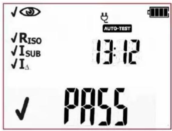
Positive test result for the tested device. The result of each single test of the sequence is positive. Green LEDs of PASS indication are on. On the right side of the screen the current time is shown.
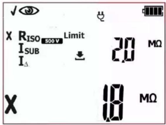
Negative test result for the tested device. One of the subsequent tests has ended with negative result - that result is displayed on screen (screen on the left, as an example, shows failed insulation resistance test). Red LEDs of FAIL indication are on.
The result is displayed on screen until ESC button is pressed, another test is run by pressing START/STOP button, measurement mode is changed, settings mode is activated or the test result is stored in the memory.
NOTE:
When a test result is incorrect and thus the entire auto test (FAIL), eg. caused by incorrect connection of a test probe, it is possible to return to the measurement that was conducted last and repeat it.

In order to do that press when the autotest summary is displayed on screen.
If the device under test, or its power cord, is equipped with portable residual current device (PRCD), its parameters shall also be checked. – see section 4.6 of this manual.
More messages displayed by the tester are described in section 2.1.2 of this manual.
4.5 Testing extension cords and IEC (power supply) cables
This test is performed to evaluate the technical condition of power cords and extension leads.
Many devices are provided with detachable power cords, which should be tested as the extension cords. Extension cords may be either simple, limited to a short cable terminated with a plug or socket, or more complex with the length of several tens metres, drum, cassette, sockets and also have a residual current device or filtering units. This also applies to power cords detachable from the powered equipment.
Extension cord is a portable device exposed to damage, especially when used at construction sites or in other severe conditions. Apart from mechanical impacts, damage may also be caused by e.g. high external temperature or internal overheating due to high current flow. Extreme temperatures are the major cause of deterioration. Therefore extension or power supply cord should be frequently tested. As in the case of power tools, an important part of the test is the visual check. After the visual check the following electrical safety tests should be performed: PE resistance and insulation resistance and polarisation of conductors' check.

After passing visual examination check (press PASS button), when the AUTO-TEST (AUTO-TEST icon is displayed) mode is on, the tester will automatically run subsequent tests. The ongoing measurements can be stopped by pressing START/STOP button.
NOTE:
If the IEC testing procedure includes the measurement of PE continuity with 10A test current, the tester has to be powered from the mains. When it's not connected the test sequence can't be initiat-
ed, mains plug icon: is lashing. In order to start the measurements, the mains power supply must be connected.
PAT-2E and PAT-10 testers allow to run the tests from their batteries when the mains power supply is

disconnected. In order to do that, press and hold IEC button for 3 seconds. The tester will enter the battery powered measurement mode. If the measurement procedure included some tests requiring mains power supply (eg. I_ , I_T ) they will be turned off. If the measurement of R _PE with 10A test current has been selected, it will be switched into 200mA test current version. Limits and test time duration settings remain unchanged. After changing the measurement mode (selecting another autotest or manual test), the tester will return to default settings that require mains power supply.


Press IEC button to go to the testing pro-

cedure for cables (LED is on) – icons representing all subsequent tests will be displayed on screen.
②
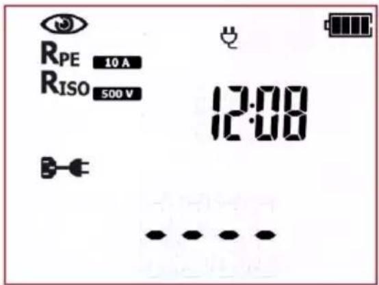
The tester is in IEC testing mode. On the right side the current time is shown.
③

Press SET/SEL button to set the measurement parameters.
④

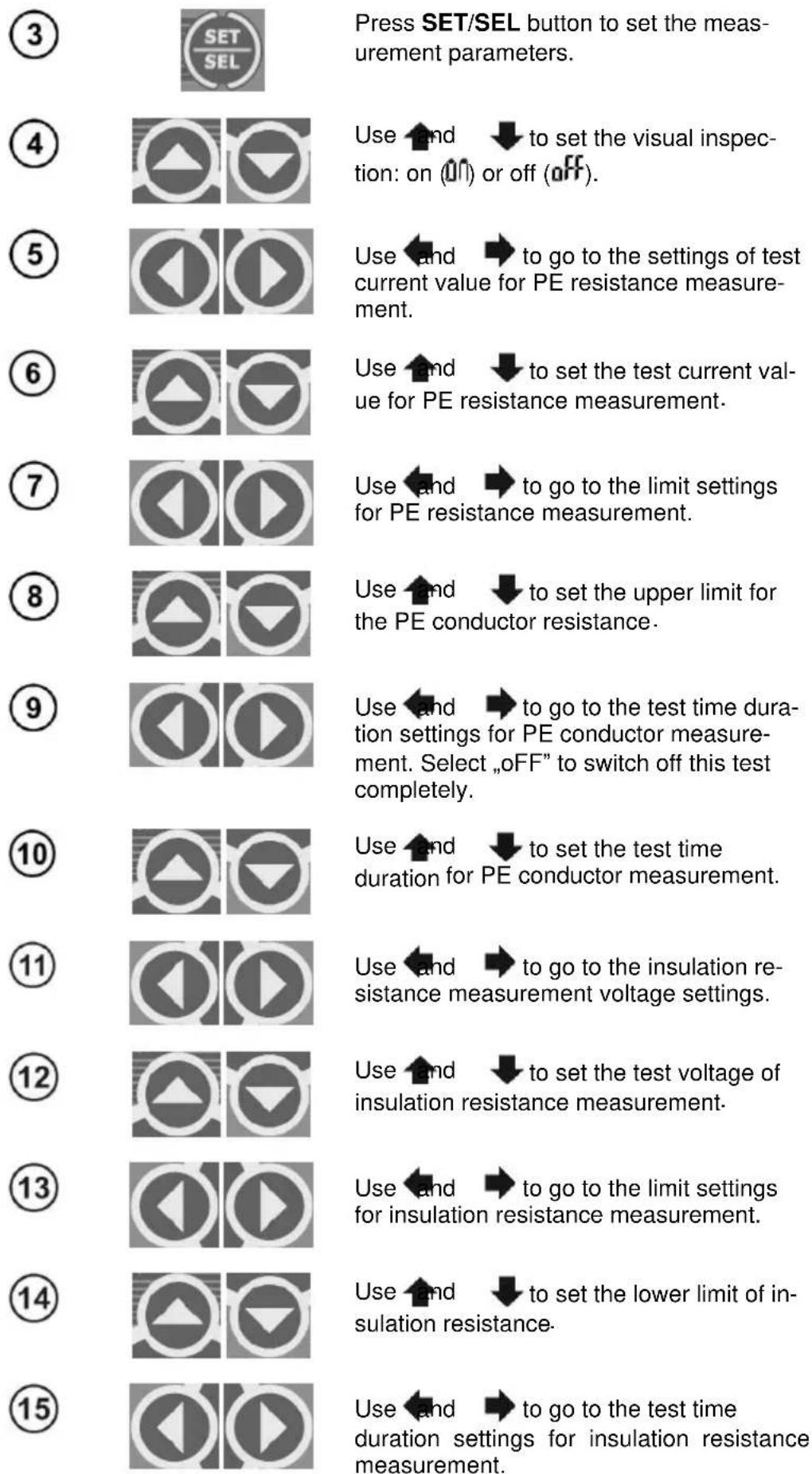
Use and to set the visual inspection: on (0) or off ( ) off
⑤

Use and to go to the test current value settings for PE resistance measurement.
⑥

Use ↑ and ↓ to set the value of the test current for the PE conductor resistance measurement.
⑦

Use and → to go to the limit settings for PE resistance measurement.
⑧

Use ↑ and ↓ to set the upper limit for the PE conductor resistance.
⑨

Use and to go to the test time duration settings for PE conductor resistance measurement.
10

Use ↑ and ↓ to set the test time duration for PE conductor resistance measurement.
11

Use and to go to the insulation resistance measurement voltage settings.
12

Use ↑ and ↓ to set the test voltage of insulation resistance measurement.
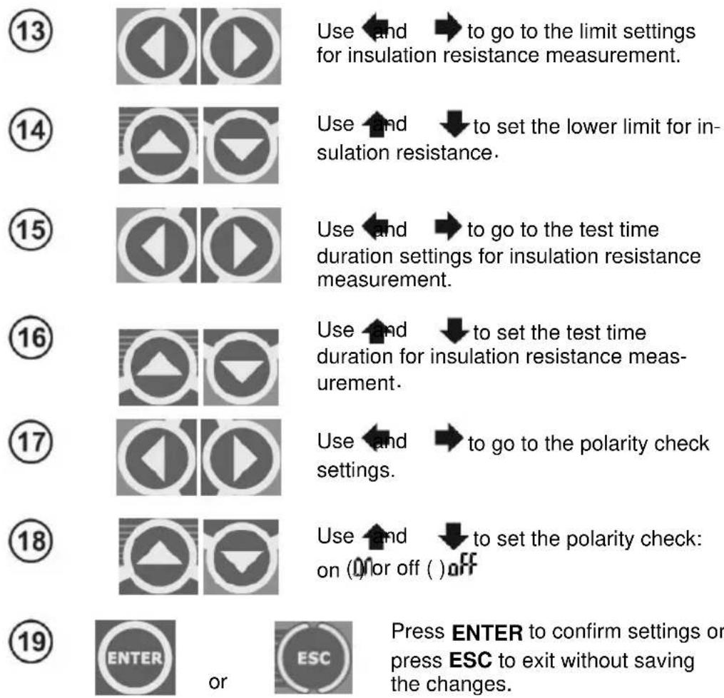
Use and to go to the limit settings for insulation resistance measurement.
Use ↑ and ↓ to set the lower limit for insulation resistance.
Use and to go to the test time duration settings for insulation resistance measurement.
Use and to set the test time duration for insulation resistance measurement.
Use and to go to the polarity check settings.
Use ↑ and ↓ to set the polarity check: on (0) or off ( ) off
Press ENTER to confirm settings or press ESC to exit without saving the changes.
20
The inspection of the tested cable (extension cord) must be carried out).
Condition of the cable, plug and sockets should be checked. It is vitally important to check the contacts of the plug and sockets inside the extension cord. As a result of high current flow, the contacts become degraded. On this occasion, check bolts holding the wire for tightening, and other elements that affect the proper operation of the device and safety of the user.
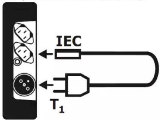
21 If the result of the visual inspection is positive, connect the tested device according to the diagram below (the device should be turned on).
22

Press START/STOP button. The visual inspection mode is on.
23
natural_image
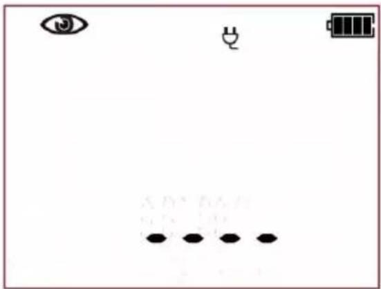
Simple diagram with eye, battery, and dot pattern (no text or symbols)The tester is waiting for the evaluation of the cable's (extension cord) condition after completing visual inspection.
24
Press PASS (V) or FAIL button (X) to evaluate the tested cable's condition: PASS means positive visual examination result - the tester will automatically run the sequence of tests. FAIL - means negative visual examination result. Irregularities in the cord have been found. Further measurements will not be conducted.
25
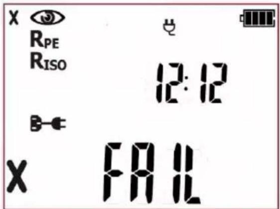
Negative visual inspection result, further measurements will not be conducted. Red LEDs of FAIL indication are on. On the right side of the screen the current time is shown.
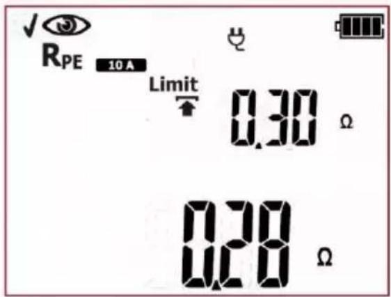
Positive visual inspection result. The tester will automatically run the subsequent tests: RPE.
26
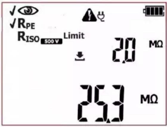
Measurement of PE protective conductor has been completed. If the measurement result is negative, further measurements will not be conducted. In case of the positive test result: the tester will automatically run the subsequent test: Riso.
27
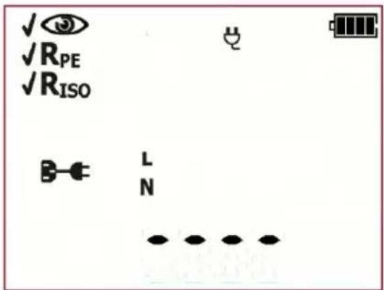
Measurement of insulation resistance has been completed. If the measurement result is negative, further measurements will not be conducted. In case of the positive test result: the tester will automatically run the subsequent tests – polarity check.
Additional information displayed by the tester when it detects problems in the cable during polarization test:
| LN | Lack of L line continuity. |
| LN | Lack of N line continuity. |
| LN | Lack of L and N lines continuity. |
| LN | Shorted L and N. |
| LN | Swapped L and N. |
28
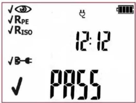
Positive test result for the tested device. The result of each single test of the sequence is positive. Green LEDs of PASS indication are on. On the right side of the screen the current time is shown.
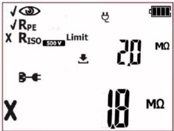
Negative test result for the tested device. One of the subsequent tests has ended with negative result - that result is displayed on screen (screen on the left, as an example, shows failed insulation resistance test). Red LEDs of FAIL indication are on.
The result is displayed on screen until ESC button is pressed, another test is run by pressing START/STOP button, measurement mode is changed, settings mode is activated or the test result is stored in the memory.
Every socket in multi socket extension cords shall be tested.
If the power cord (extension cord) is equipped with portable residual current device (PRCD), its parameters shall also be checked – see section 4.6 of this manual.
Notes:
- The tested device must be turned on.
- The conditions for testing PE and insulation resistance are the same as the ones for testing appliances (see previous sections).
More messages displayed by the tester are described in section 2.1.2 of this manual.
4.6 Measurement of portable residual current device trip time – PRCD
This test is performed to evaluate the technical condition of a portable residual current device. PRCD measurements require the tester to be powered from the mains. When it's not connected the test
can't be initiated, and the mains plug icon is flashing. In order to start the selected set of tests, the mains power supply must be connected.
①

Press PRCD button to go to the testing procedure for residual current device

PRCD
will be displayed on screen, along with nominal trip current I_n : 10mA or 30mA (after pressing PRCD button again). The testing procedure for both current values is the same.
②
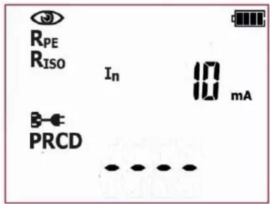
The tester is in PRCD trip time measurement mode.
③

Press SET/SEL button to set the measurement parameters.
④

Use ↑ and ↓ to set the visual inspection: on ( ) or off ( ) off
⑤

Use and to go to the settings of test current value for PE resistance measurement.
⑥

Use ↑ and ↓ to set the test current value for PE resistance measurement.
⑦

Use and to go to the limit settings for PE resistance measurement.
21
Use and to set the measurement for x1 multiplication with the initial phase of 180^ .
22
Use and to choose whether the measurement for I_ n × 1 with the initial phase of 180^ is to be performed („yES“) or switched off („no“).
23

Use and to set the measurement for I_ n x5 multiplication with the initial phase of 0^ .
24

Use and to choose whether the measurement for I_ n x5 with the initial phase of 0^ is to be performed („yES“) or switched off („no“).
25
Use and to set the measurement for I_ n x5 multiplication with the initial phase of 180^ .
26
Use and to choose whether the measurement for I_ n x5 with the initial phase of 180^ is to be performed („yES“) or switched off („no“).
27

Use and to go to the selection screen of PRCD type.
26

Use ↑ and ↓ to choose whether the measurement is to be conducted for the standard PRCD type ('Stdn') or for the 'S' type ('safety'). The RCD-S (also known as SPE-PRCD) types additionally disconnect (monitor) the PE conductor, approved for use in some countries.
28

or
Press ENTER to confirm settings or press ESC to exit without saving the changes.
connect the tested device according to the diagram below.
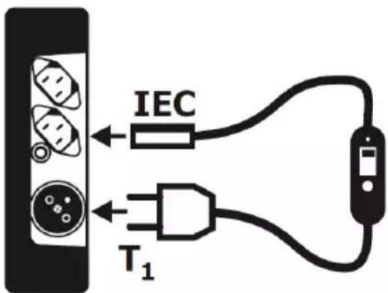
29

Press START/STOP button. The measurement of resistance of protective conductor will commence.
The tester will perform the tests in the same way as in the IEC test mode (clause 4.5 of this manual). Additionally, during the visual inspection, the proper operation of the TEST button on the PRCD should be checked.

The polarity test and the differential leakage current measurement for PRCD (for PRCD-S also for PE continuity measurement) are carried out with the mains voltage present at the test terminal.
During the polarity test and the differential leakage current measurement (for PRCD-S also during PE continuity test), a message saying 'turn on Prcd' (turn on PRCD) may turn up on screen. Turn on the PRCD switch to continue the test.

When measuring the differential leakage current, switch on the PRCD.
In addition to IEC like measurements, the tester will measure the PRCD trip time:
30
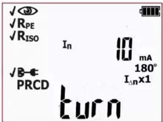
Switch on PRCD. Tester will commence the first measurement. If PRCD trips, a message prompting to switch on the RCD will be displayed on the main screen: 'turn on PRCD'.
If the PRCD switch is turned on and the message 'turn on Prcd' is still displayed, the PRCD is faulty (or other circuit element), press the FAIL button to conclude the test.
31
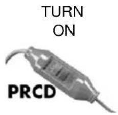
PRCD must be switched on every time after it trips. Each consecutive measurement will be performed automatically. The tester will wait for 2 minutes for the PRCD to be turned back on. After this time, when any of the following occurs: PRCD is not switched on, the circuit is damaged, the FAIL button is pressed, the tester indicates lack of continuity on the measured circuit - the test result will be negative.
32
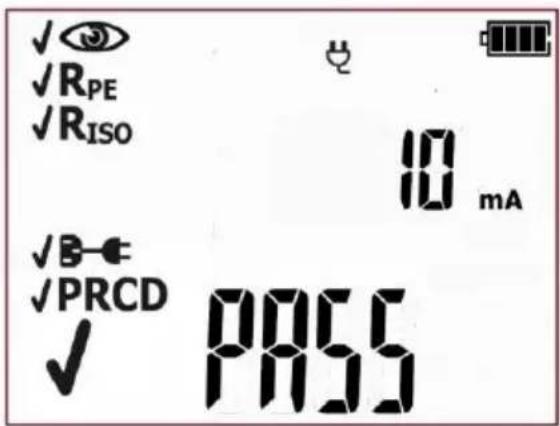
Correct result. The result of each single test of the sequence is positive. Green LEDs of PASS indication are on.
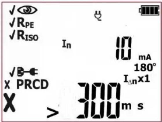
Incorrect result. One or more of the measured parameters are above the permissible threshold. Red LEDs of FAIL indication are on.
The result is displayed on screen until ESC button is pressed, another test is run by pressing START/STOP button, measurement mode is changed, settings mode is activated or the test result is stored in the memory.
Additional information displayed by the tester
| >300ms | Measuring range is exceeded. | |
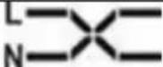 | Swapped L and N. | |
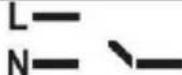 | Lack of L and/or N lines continuity. | |
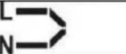 | Shorted L and N. | |
More messages displayed by the tester are described in section 2.1.2 of this manual.
Notes:
- The tested device must be turned on.
- Switch on PRCD immediately after it trips.
- Unlike the IEC test, the measurement of PRCD can be limited to the PRCD trip time test only (and exclude all other component measurements including polarity check).
4.7 Compensation of the test lead's resistance (auto-zeroing)
The tester is factory calibrated to work with the test lead and with the probe supplied with it, as standard. Other test leads (probes, crocodile clips) can be used as well. Resistance of non-standard test leads can adversely affect the result of PE resistance measurement (R _PE ). In order to eliminate the influence of the test leads' resistance on the result, it is advised to perform a test lead compensation (auto-zeroing). The tester enables to perform automatic compensation of test leads. The auto-zeroing procedure starts followed by pressing and holding SET/SEL button for approx. 3 seconds. This function is available when:
- the tester is in R_PE 200mA or R_PE 10A manual mode;
- the tester is in autotest mode for Class I appliances.
The compensation is common for all R _PE (200mA, 10A – for PAT-10) tests, both in manual and autotest mode, regardless of the mode it was carried out in. The compensation remains in force even after turning the tester on and off, until deactivated by the user, as described below.
During the test lead compensation procedure the PAT-10 tester must be connected to mains power supply.
The test lead compensation procedure:


Press and hold SET/SEL button for approx. 3s (in autotest CL I or manual RPE mode).

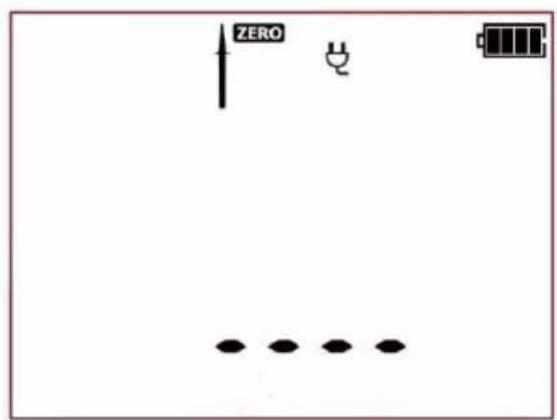
The tester has switched into the test lead compensation mode. ZERO icon is flashing.
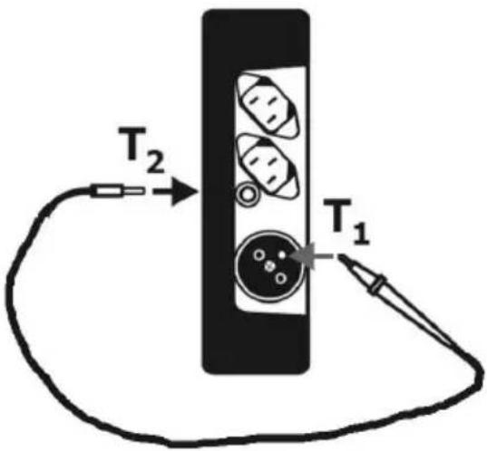
Touch the PE pin of the T1 test socket with the probe connected to socket T2.
③

Press START/STOP button. The resistance of the protective conductor is being measured, so its influence on the test result can be ruled out.
④
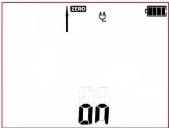
The compensation value has been measured. On is displayed on the screen, along with the permanent
ZERO symbol. After 3 seconds the tester returns to measurement mode. The active test lead compensation is indicated by
ZERO icon being displayed on screen during the tests of R_PE (200mA, 10A) and CL I autotests. The compensation resistance will be taken into account then displaying test results of R_PE
In order to remove the compensation of the lead resistance (return to default calibration), perform the above-mentioned steps with open test lead - ZERO icon will disappear and OFF message will be displayed. After 3 seconds the tester will return to measurement mode.
More messages displayed by the tester are described in section 2.1.2 of this manual.
5 Memory of measurement results
The PAT-2, PAT-2E and PAT-10 testers have memory divided into 10 banks of 99 cells each. Thanks to dynamic memory allocation, each of the memory cells can contain different quantity of single measurement results, depending on the needs. That allows for the optimal use of the memory. Each measurement result can be stored in a memory cell marked with a selected number and in a selected memory bank. Thanks to this, the user of the tester can, at his sole discretion, assign memory cell numbers to individual measurement points and the memory bank numbers to individual facilities. The user may also perform measurements in any chosen sequence and repeat them without losing other data.
Memory of measurement results is not deleted when the tester is switched off. Thanks to this, the data can be later read or sent to a computer. The number of a current memory cell or memory bank is not changed either.
Notes:
- A single cell can be used for storing a complete set of measurement results (including additional data like limits and pre-set times) for one AUTO test or IEC or PRCD, or a result of a single manual test (with additional data).
- After entering the measurement result, the ID number of the cell is automatically incremented.
- It is recommended to delete the memory after reading the data or before performing a new series of measurements that may be stored into the same memory cells as the previous ones.
5.1 Storing the measurement results in the memory
①

After completing measurement press ENTER. The tester will turn into the mode for storing the test results.
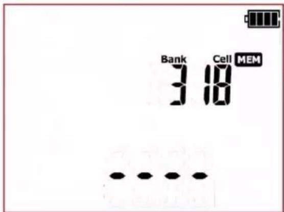
The cell is empty.
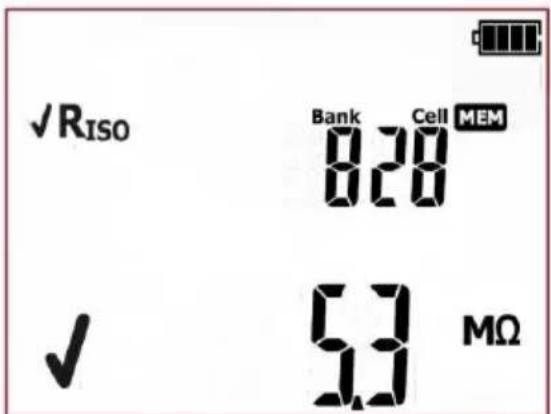
A cell occupied by a single test result. An icon indicating the test type and the main result is displayed on screen.
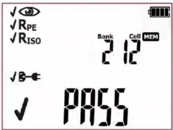
A cell occupied by AUTO test, IEC or PRCD test result (corresponding icons for subsequent tests, along with results are displayed on screen).

Use and buttons to preview the results stored in the selected cell. If any.
To change the cell number or bank number:


When the cell number is flashing, use and buttons to set the desired number of the cell.


Press SET/SEL button – bank number is flashing.


Use ↑ and ↓ buttons to set the desired number of the bank.


After selecting the desired bank and cell, press ENTER button, to save the result in the memory. Recording is indicated by a triple beep sound.
Press ESC to return to the measurement screen without saving.
If you try to store data in an occupied memory cell, the following warning message will appear: OVER (reference to word OVERwrite):
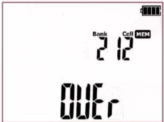


or
Press ENTER, to overwrite the result or ESC, to cancel and select other cell or bank.
Note:
- Complete set of results for each measurement function is saved to memory (main and additional ones), along with its parameters.
5.2 Browsing memory data


Press MEM button to enter the memory
browsing function: MEM (LED on).



Use and buttons to preview the test results components stored in the selected cell, if any exist.
To change the cell number or bank number:


When the cell number is flashing, use ↑ and ↓ buttons to set the desired number of the cell.

Press SET/SEL button – bank number is flashing.


Use and buttons to set the desired number of the bank.
5.3 Deleting memory data
A single cell, bank or the entire memory can be deleted.
5.3.1 Deleting cel data
①

Press MEM button to enter the memory browsing function: MEM (LED

is on).
②
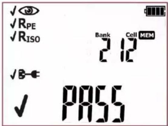
Set the cell number to be deleted acc. to point 5.2.
③

Press ENTER button.
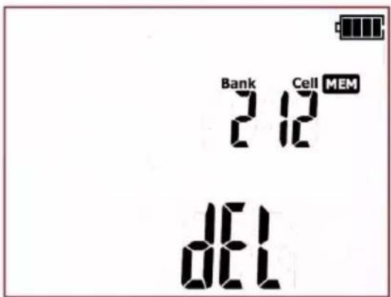
Then symbol dEL (delete) will be displayed to indicate the readiness for deleting.
④

Press ENTER button.
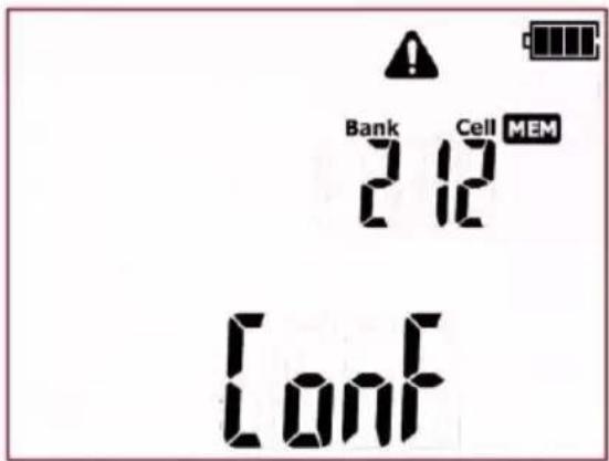
⚠ and ConF symbols will appear, asking to confirm deletion.

Press ENTER button again to delete the selected cell.
After deleting the cell, the tester beeps three times. Press ESC to cancel and return to memory browsing mode.
The contents of the cell has been deleted.
5.3.2 Deleting bank data
①

Press MEM button to enter the memory browsing function: MEM (LED

is on).
②
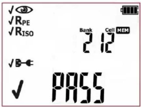
Set the bank number to be deleted acc. to point 5.2.
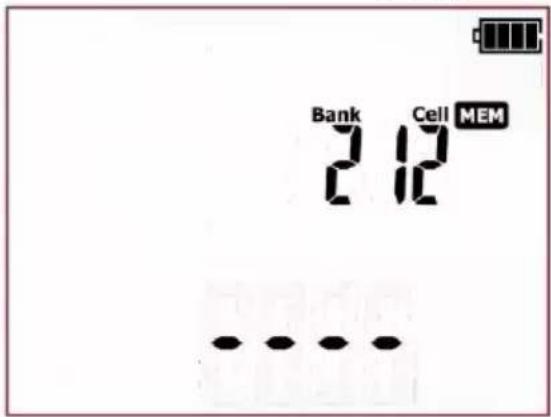
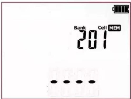
Set the cell number as ‘- -’ (before “01”) below screen will appear.
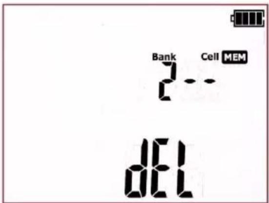
Then symbol dEL will be displayed to indicate the readiness for deleting.
③

Press ENTER button.
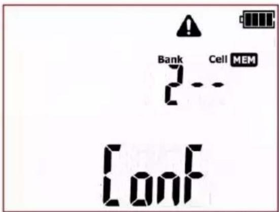
⚠️ and ConF symbols appear, asking to confirm deletion.
④
Press ENTER button again to delete the selected bank.
After deleting the bank, the tester beeps three times. Press ESC to cancel and return to memory browsing mode.
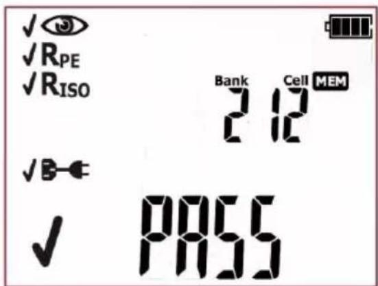
The content of the bank has been deleted, the first cell of the deleted bank is selected.
5.3.3 Deleting the entire memory data
①

Press MEM button to enter the memory browsing function: MEM

②
Set the bank number as ‘--’ (before ‘1’)...
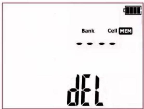
... the bank number will change into ‘--’, then symbol dEL will be displayed to indicate the readiness for deleting the entire memory data.
③

Press ENTER button.
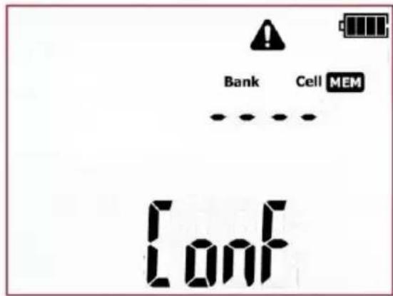
⚠️ and ConF symbols appear, asking to confirm deletion.
④

Press ENTER again.
After deleting the memory, the tester beeps three times. Press ESC to cancel and return to memory browsing mode.
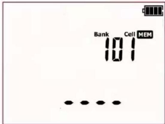
The entire memory data has been deleted.
6 Label printing
Testers PAT-2, PAT-2E and PAT-10 support printing reports/labels with Brother P750W printer. All information about the printer and its operation can be found in the operating manual provided by the manufacturer of the printer.
Printer configuration in is done on the SET menu of the tester, as described in the next section of this manual. Printing is possible:
- after completing measurement, when the final result is displayed on screen
- when browsing memory
- automatically after saving to memory.
Acquaint yourself with the printer's instruction manual prior to use.
WiFi communication on the printer works only when the printer is powered from a dedicated rechargeable battery or from AC adapter.
6.1.1 Printer configuration
The connection between the tester and the printer has to be configured, before printing labels is possible. The tester sends data to printer via WiFi connection. The last four digits of the printer's serial number is needed to configure the connection. The location of the serial number:
- on a sticker under the flap side of the printer (recommended location):
- on the bottom of the printer's packaging (cardboard box) - make sure that the packaging belongs to the right printer:
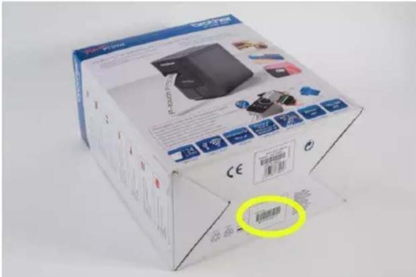
After finding the serial number, turn on (as described in section 3 of this manual) the WiFi connection (rF function) on the SET menu of the tester. WiFi icon 🐘, will appear on screen. Then enter the printer configuration mode (Print Conf).
Turn on the printer and activate the printer's WiFi mode.
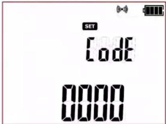
After entering the printer's configuration menu on the tester, user will be prompted to enter the connection code (CodE), as shown in the screen below:
①

When the code setting screen is displayed, the first digit of the code is flashing. Use ↑ and ↓ buttons to set the desired value.
②

Use and go to the next digit and set it in the same way as the first one.
③

After entering the code press ENTER to save the changes.
When the screen for checking connection (Prnt test) is displayed and the printer icon 📋 is flashing, the tester is establishing connection with the printer:
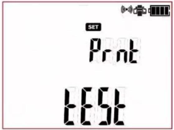
If the code is correct and the connection is properly established, the printer icon 📋 will be lit permanently, and the tester will remember the settings and will go to the settings menu (SET) of the tester. If any problem occurs the tester will return to the code input screen (CodE) - verify the correctness of the code and make sure the printer is ready, and then try to connect again.
Label and report printing is possible when the following is provided: WiFi connection is established (rF), one of the printing modes is selected (Print option) and the printer is on, with properly configured connection (proper code: CodE). The tester will display these icons on screen: 📄 and 🔵.
The configuration of the printer connection is also possible with the dedicated PC programme (Sonel Reader, PAT Plus).
NOTE:
Once the configuration process is completed, or after switching the tester off and on, it can take up to approx. 90s to establish connection with the printer. This is due to the characteristics of the printer.
NOTE:
When printing doesn't work and the printer 📄 is flashing, make sure the printer is on and properly configured. When printing doesn't work and the printer icon 📄 lits permanently on screen, check if the printer is ready to work (eg. there is no problem with consumables, ie. no tape inside).
NOTE:
It may happen that the printer has a 'P-Lite' mode active when turned on (the green LED above the P-Lite button on the printer is on). In order to connect to the tester, follow these steps:
- Turn off the P-Lite mode by holding down the P-lite button, the green LED will turn off.
- Turn on wireless transmission by holding down the wireless buton until the WI-FI LED and/or the NFC LED start flashing (it does not matter which LED will start first),
- Turn the printer off and on.
- The restarted printer should establish connection with the PAT tester with no further issues.
6.1.2 Printing after measurement
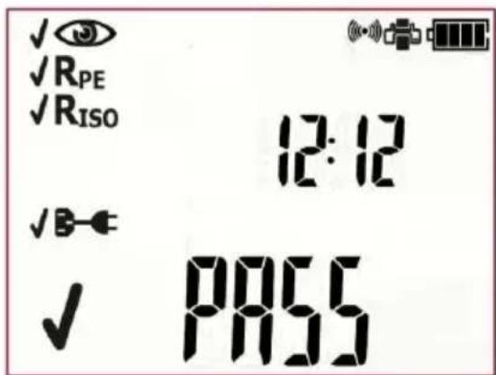
When a single test or AUTO test sequence (also IEC and PRCD) is completed, and its result is being displayed on screen):
①
②

Press print button (MEM). The label printing process will commence. When printing is in progress the tester will display Prnt on screen.
6.1.3 Printing from memory
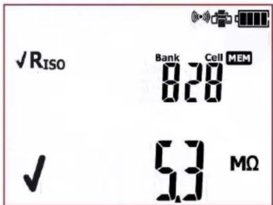
To print an already saved test, go into browse memory mode (see section 5.2 of this manual), select the bank and the cell that contain test results that are to be printed. A screen showing data of the selected cell is displayed on the tester's screen:
①
②

Press print button (MEM). The label printing process will commence. An entire content of the selected cell will be printed. When printing is in progress the tester will display Prnt on screen.
6.1.4 Printing automatically when saving to memory
If auto print mode is on (see section 3 of this manual), when saving test results into memory (see section 5.1 of this manual), after selecting bank and cell, pressing ENTER will automatically save the test result and will print a label at the same time. When printing is in progress the tester will display Prnt on screen.
6.1.5 Label types
There are two printout formats that can be used. The two types vary in the amount of measurement data on them. If the standard report has been selected ( ) the tester will print the user data, dates and the general test or AUTO test sequence result:
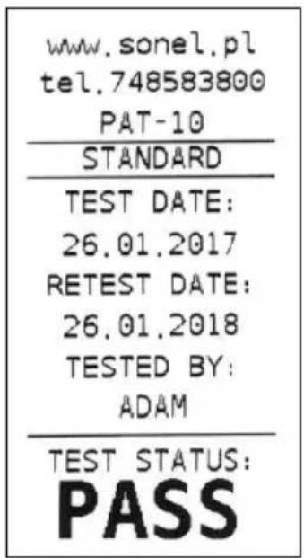
Standard report (label) for:
positive test result
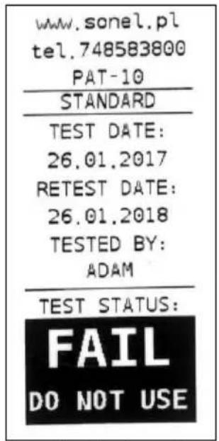
negative test result.
If the full report has been selected ( ) there tester will print the same set of data as in standard report, and additionally it will include a single test results:
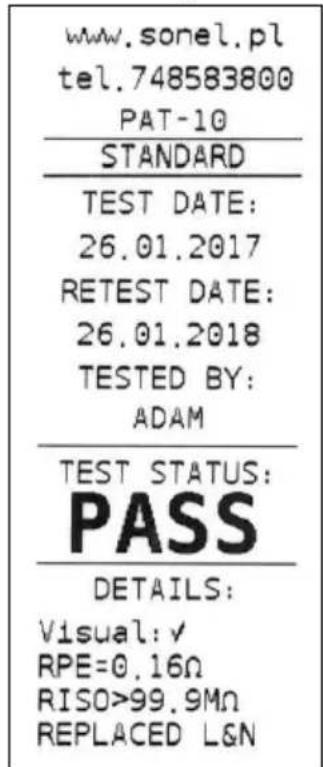
Full report (label) for:
positive test result
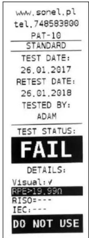
negative test result.
6.1.6 Printout data configuration with PC software
Connect the tester to a computer and set up the connection in accordance with section 7.2 of this manual. Then run the tester configuration module and the printout wizard (follow the instructions of the PC software user manual). Following data can be activated and filled in:
- contact data field - three lines. The first field on the top of the printout.
- additional field - allows to add custom printout description (eg. standard name, tester's serial number, etc.).
- retest date – the date when the tested appliance should be tested again. Allows to set the retest cycle in months. Selected value will be added to the test date and printed out as a retest date.
- tested by – name (eg. Family name, initials, etc.) of the person who did the testing.
Fields 'tested by' and 'test status' are always printed.
If any of the above mentioned fields are not activated, the tester will skip them when printing - printouts will be shorter:
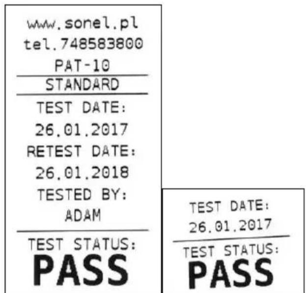
Exemplary standard label with all the fields: filled in left empty.
6.1.7 Placing the printer inside a carrying case
Carrying case has enough room to store not only the tester, but printer too. The space dedicated for that is in the lower part of the case. In order to put the printer inside the case undo zippers and Velcro straps, then fit the printer inside, and fasten the straps back on, as shown in the picture below:
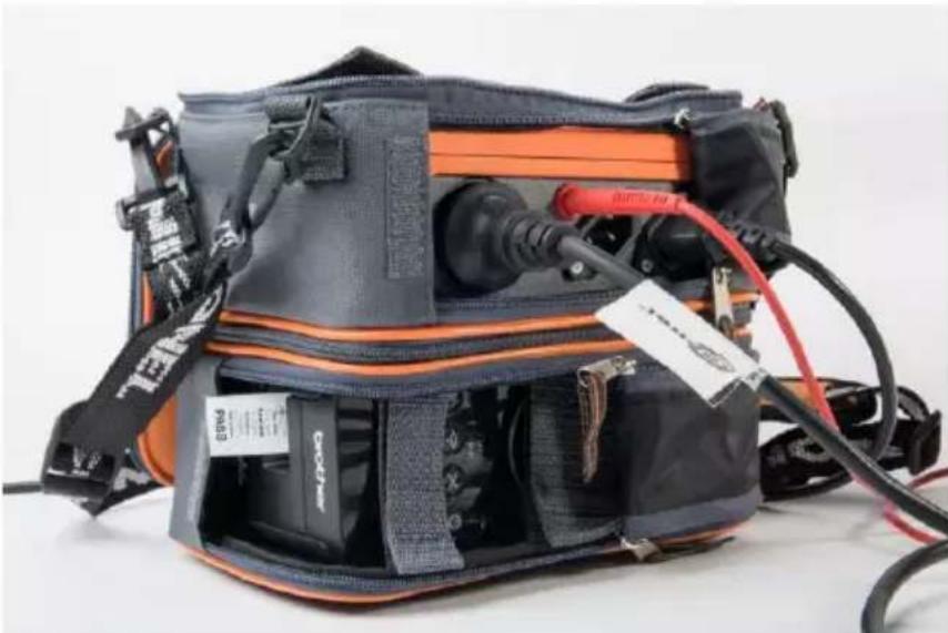
natural_image
Close-up of a black and orange safety harness with attached cables and connectors (no visible text or symbols)After finishing the work, the bottom part of the carrying case can be zipped up for better protection of the printer during transport.
7 Data transmission
7.1 Accessories required to connect the tester to PC
The tester can be connected to a PC via USB cable and appropriate software. If the software has not been purchased along with the tester, it can be downloaded from the manufacturer's website, purchased from the manufacturer or from an authorized distributor.
Possessed PC software can be used with many instruments manufactured by Sonel S.A., equipped with USB interface, or other (depending on the instrument). Contact manufacturer or local distributor for more detailed information.
7.2 Data transmission and tester configuration via USB port
1.

Press MEM button to enter the memory browsing
function: MEM (LED

-
Connect the cable to the USB port of the computer and the USB socket of the tester.
-
Run the software for communicating with the tester and follow the on-screen instructions. The tester will display below message:
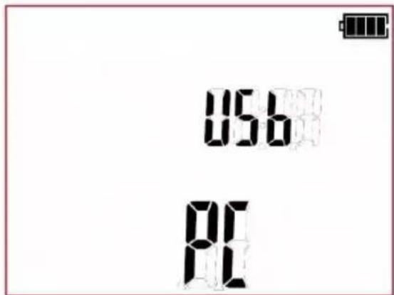
8 Firmware update
- In accordance with the guidelines of Section 3 of this manual, enter the meter's firmware update mode: UPdT
- Connect the cable to the USB port on the computer and the USB socket on the tester.
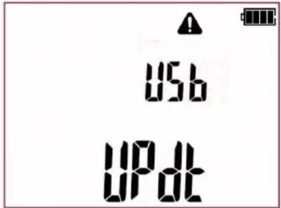
- Run a program for updating the firmware and follow on-screen instructions.
9 Power supply of the tester
9.1 Monitoring the power supply
The charge level of the batteries or rechargeable batteries is indicated by the symbol in the right upper corner of the display on a current basis:
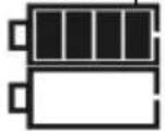
rechargeable batteries are charged.
rechargeable batteries are nearly discharged. Only voltage measurement is possible.
No battery symbol on screen (with charger connected) indicates that the battery is either disconnected or corrupted.
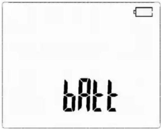
Rechargeable batteries completely discharged.
The tester switches off automatically after 5 seconds.
9.2 Charging the rechargeable battery pack
CAUTION!
The PAT-2/2E/10 testers are powered from SONEL battery pack, which includes NiMH 7,2V batteries, and it may be replaced only by the authorized service point.
The PAT-2/2E/10 testers feature built-it battery charger that only works with the original battery pack provided by the manufacturer.
Charging commences once the power supply has been connected to the tester regardless of the fact whether the tester is turned on or off. The only difference is the charging mode, as described below. The charging process is indicated on the screen by displaying animated symbol of battery being charged.
Battery charging modes:
- the tester (user interface) is switched off: the battery pack is charged in 'quick charging' mode - the charging process takes approx. 4 hours. Completed charging is indicated by full battery symbol, FULL message and beep. In order to completely turn off the tester, unplug the power charger.
- the tester (user interface) is switched on: the battery pack is charged in ‘charging in the background’ mode.
In order to completely turn off the tester, unplug the power charger and turn the tester off.
CAUTION! Do not power the meter from sources other than those listed in this manual.
Notes:
- Due to the interferences in the mains, the process of battery charging may finish prematurely. When charging time is too short, turn off the tester and start charging again.
Additional information displayed by the tester
| Message | Cause | Proceeding |
| ACU H°C | The temperature of the batteries is too high. | Wait for the batteries to cool down.Start the charging procedure again. |
| ACU L°C | The temperature of the batteries is too low. | Wait for the batteries to warm up. Start the charging procedure again. |
| ACU Err | Emergency. Disconnected or corrupted batteries. | Contact the manufacturer's service department. |
9.3 General principles of using Ni-MH batteries
- Store the batteries (the tester) in a dry, cool and well ventilated place and protect them from direct sunlight. The ambient temperature in the case of prolonged storage should not exceed 30^ C. If the batteries are stored for a long time in a high temperature, then the occurring chemical processes may reduce their lifetime.
- Ni-MH batteries normally withstand 500-1000 charging cycles. The batteries reach their maximum capacity after being formatted (2-3 charge and discharge cycles). The most important factor which influences the lifetime of the battery is the depth of discharge. The deeper the discharge level of the battery, the shorter its lifetime will be.
- The memory effect is limited in the case of Ni-MH batteries. These batteries may be charged at any point with no serious consequences. However, it is recommended to discharge them completely every few cycles.
- During storage of Ni-MH batteries they self-discharge at the rate of approximately 20% per month. Keeping them at high temperatures may double the speed of this process. In order to prevent excessive discharge of batteries, after which it would be necessary to format them, it is recommended to charge the batteries from time to time (even if not in use).
- Modern fast chargers detect both too low and too high a temperature of batteries and react to the situation adequately. Too low a temperature should prevent the start of the process of charging which might damage the battery irreparably. An increase of the temperature of the battery is a signal to stop charging and is a typical phenomenon. However charging at a high ambient temperature apart from reducing the lifetime causes an accelerated increase of the temperature of the battery, which will be not charged to its full capacity.
- Remember that fast charging gets the batteries to be charged to approximately 80% of their capacity. Better results may be obtained if the process of charging is continued: the charger goes then to the phase of charging with a low current and after next couple of hours the batteries are charged to their full capacity.
- Do not charge or use batteries in extreme temperatures. Extreme temperatures reduce the lifetime of batteries. Avoid placing devices powered from batteries in very hot environments. The nominal working temperature must be absolutely observed.
10 Replacing fuses
PAT-2E and PAT-10 testers are equipped with two fuses (0216016.MXP, 5x20mm 16A Littelfuse) that are replaceable by user. When needed unscrew and remove the fuse containers on the bottom side of the tester:
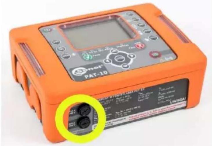
The next step is to replace the fuse with a new one and fit it together with its container back into the tester.
11 Cleaning and maintenance
NOTE!
Apply solely the maintenance methods specified by the manufacturer in this manual.
The casing of the tester may be cleaned with a soft, damp cloth using all-purpose detergents. Do not use any solvents or cleaning agents which might scratch the casing (powders, pastes, etc.). Clean the probe with water and dry it. Before the probe is stored for a prolonged period of time it is recommended to grease it with any machine lubricant. Test leads should be cleaned with water and detergents, and then dried.
The electronic system of the meter does not require maintenance.
12 Storage
In the case of storage of the device, the following recommendations must be observed:
- Disconnect all the test leads from the tester,
- Clean the tester and all its accessories thoroughly,
• Wind the long test leads onto the reels, - In order to prevent a total discharge of the batteries in the case of a prolonged storage, charge them from time to time.
13 Dismantling and disposal
Used electric and electronic equipment should be collected selectively, i.e. it must not be placed with other kinds of waste. Used electronic equipment should be sent to a collection point in accordance with the Used Electrical and Electronic Equipment Act. Before the equipment is sent to a collection point, do not dismantle any elements. Observe the local regulations concerning disposal of packages, worn-out batteries and accumulators.
14 Technical data
14.1 Basic data
⇒ Abbreviation ‘m.v.’ used in the specification of measurement accuracy means a standard measured value.
⇒ Ranges and accuracies are additionally provided according to DIN VDE 404-1.
Measurement of network voltage
| Display range | Resolution | Accuracy |
| 195,0 V...265,0 V | 0,1 V | ±(2 % m.v. + 2 digits) |
• measurement of the mains voltage between L and N of the power supply
Measurement of network frequency
| Display range | Resolution | Accuracy |
| 45,0 Hz...55,0 Hz | 0,1 Hz | ±(2 % m.v. + 2 digits) |
• measurement of the mains voltage frequency of the power supply
Measurement of PE network (mains) voltage
| Display range | Resolution | Accuracy |
| 0,0 V...59,9 V | 0,1 V | ±(2 % m.v. + 2 digits) |
• measurement of the mains voltage between PE and N of the power supply
* for U < 5V accuracy is not specified
Measurement of L-N circuit resistance
| Display range | Resolution | Accuracy |
| 10...999 Ω | 1 Ω | ± (6 % m.v. + 5 digits) |
| 1,00...4,99 kΩ | 0,01 kΩ |
• test voltage: <50 V AC
• short-circuit current: < 20 mA
- R L-N measurement applies to resistance objects. In the case of inductive objects, the result may be burdened with an additional error.
Measurement resistance of protective conductor I=200mA (only Protection Class I)
| Display range | Resolution | Accuracy |
| 0,00 Ω...0,99 Ω | 0,01 Ω | ±(4 % m.v. + 8 digits) |
| 1,00 Ω...19,99 Ω | ±(5 % m.v. + 8 digits) |
| Influencing factor | Designation | Additional uncertainty |
| Position | E_1 | 0 % |
| Supply voltage | E_2 | 0 % |
| Temperature | E_3 | 0,1 %/°C for R ≥ 0,5 Ω0 %/°C for R < 0,5 Ω |
- unloaded output voltage: 4 ... 12V DC
• Test current: ≥ 200mA for R = 0.2 ... 1.99 Ω - adjustable upper limit in the range of: 0.01 19.99 with resolution 0.01
- adjustable measuring time: 3...180s with a resolution of 1s
PAT-10
Measurement resistance of protective conductor I=10A (only Protection Class I)
| Display range | Resolution | Accuracy |
| 0,000 Ω...0,999 Ω | 0,001 Ω | ±(4 % m.v. + 6 digits) |
| 1,00 Ω...1,99 Ω | 0,01 Ω |
| Influencing factor | Designation | Additional uncertainty |
| Position | E_1 | 0 % |
| Supply voltage | E_2 | 0 % |
| Temperature | E_3 | 0,1 %/°C |
- unloaded output voltage: <12V AC
• test current: ≥ 10A for R ≤ 0,1 Ω
• adjustable upper limit in the range of: 0,01 Ω ...1,99Ω with resolution 0,01Ω
• adjustable measuring time in the range of: 3...180s with resolution of 1s
PAT-2E
PAT-10
Measurement of insulation resistance using test voltage of 250V
Test range according to IEC 61557-2 for U_N=250V:0,25M99,9M
| Display range | Resolution | Accuracy |
| 0,00...9,99 MΩ | 0,01 MΩ | ± (5 % m.v. + 8 digits) |
| 10,0...99,9 MΩ | 0,1 MΩ |
| Influencing factor | Designation | Additional uncertainty |
| Position | E_1 | 0 % |
| Supply voltage | E_2 | 0 % |
| Temperature | E_3 | 0,1 %/°C |
| Capacity | E_7 | 0 % for R ≤ 20 MΩUnspecified for R > 20 MΩ |
• Accuracy of generated voltage (Robc [Ω] ≥ 1000*U _N [V]): -0 % +30 % from the set value
• nominal current: min 1 mA ... 1.4 mA
• adjustable lower limit within the range of 0,1 MΩ...99,9 MΩ with resolution of 0,1MΩ
- adjustable measuring time: 3s...180 s with a resolution of 1s
• detection of a dangerous voltage before commencing a measurement
• discharging the object tested
Note: For R <0,25 MΩ, the accuracy is not specified.
Measurement of insulation resistance using test voltage of 500V
Test range according to IEC 61557-2 for UN = 500V: 0,50 MΩ...99,9 MΩ
| Display range | Resolution | Accuracy |
| 0,00...9,99 MΩ | 0,01 MΩ | ± (5 % m.v. + 8 digits) |
| 10,0...99,9 MΩ | 0,1 MΩ |
| Influencing factor | Designation | Additional uncertainty |
| Position | E_1 | 0 % |
| Supply voltage | E_2 | 0 % |
| Temperature | E_3 | 0,1 %/°C |
| Capacity | E_7 | 0 % for R ≤ 20 MΩUnspecified for R > 20 MΩ |
• Accuracy of generated voltage (Robc [Ω] ≥ 1000*U _N [V]): -0 % +30 % from the set value
• nominal current: min 1 mA ... 1.4 mA
• adjustable lower limit within the range of 0,1...99,9 MΩ with resolution of 0,1MΩ
- adjustable measuring time: 3s...180s with a resolution of 1s
• detection of a dangerous voltage before commencing a measurement
• discharging the object tested
Note: For R < 0,50 MΩ, the accuracy is not specified.
Measurement of substitute leakage current
| Display range | Resolution | Accuracy |
| 0,01 mA...3,99 mA | 0,01 mA | ± (5 % m.v. + 2 digits) |
| 4,0 mA...19,9 mA | 0,1 mA |
| Influencing factor | Designation | Additional uncertainty |
| Position | E_1 | 0 % |
| Supply voltage | E_2 | 0 % |
| Temperature | E_3 | 0,075 %/°C |
- opening voltage: 25 ... 50V
• internal resistance of the testing device 2k ± 20%
• adjustable upper limit in the range of: 0,01 mA...19,9 mA with resolution of 0.01mA/0.1mA - adjustable measuring time in the range of: Cont , 3...180s with resolution of 1 s
Measurement of differential leakage current
Note: In the half-time of the measurement, the tester automatically changes the polarity of the test socket and as a final result it displays the value of higher leakage current.
| Display range | Resolution | Accuracy |
| 0,10 mA...3,99 mA | 0,01 mA | ± (5 % m.v. + 2 digits) |
| 4,0 mA...19,9 mA | 0,1 mA |
| Influencing factor | Designation | Additional uncertainty | |
| Position | E_1 | 0 % | |
| Supply voltage | E_2 | 0 % | |
| Temperature | E_3 | 0,1 %/°C | |
| Power consumption of the tested unit | E_4 | Current common | Additional uncertainty |
| 0 A...4 A | 0 | ||
| 4 A...8 A | ±0,03 mA | ||
| 8 A...16 A | ±0,08 mA | ||
| Low frequency magnetic field | E_5 | 2 digits I < 4 mA0 digits for I ≥ 4 mA | |
| The shape of the network voltage (CF) | E_8 | 0 % | |
• adjustable upper limit in the range of: 0,10 mA...19,9 mA with resolution of 0.01mA/0.1mA
• adjustable measuring time in the range of: 4 s...180 s with resolution of 1 s
- when measuring devices whose power consumption exceeds 10A, the measurement time is automatically limited to maximum of 15s.
Measurement of touch leakage current
Note: In the half-time of the measurement, the tester automatically changes the polarity of the test socket and as a final result it displays the higher value.
| Display range | Resolution | Accuracy |
| 0,001 mA...4,999 mA | 0,001 mA | ± (5 % m.v. + 3 digits) |
| Influencing factor | Designation | Additional uncertainty |
| Position | E_1 | 0 % |
| Supply voltage | E_2 | 0 % |
| Temperature | E_3 | 0,25 μA/°C |
| The shape of the network voltage (CF) | E_8 | 0 % |
- the bandwidth of test current results from the measuring system with adjusted touch current which simulates human perception and reaction, in accordance with EN 60990: 2002
• adjustable upper limit in the range of: 0,01 mA...4,99 mA with resolution 0,01mA - adjustable measuring time in the range of: 4s...180s with resolution of 1 s
- when measuring devices whose power consumption exceeds 10A, the measurement time is automatically limited to maximum of 15s.
Measurement of PRCD parameters
PRCD tripping time measurement for sine t_A differential current
Measurement range in acc. with IEC 61557: 0ms ... up to the upper limit of displayed value
| RCD type | Differential current of the PRCD | Rated Current Multiplication Factor | Measurement range | Resolution | Accuracy |
| General | 10mA | 1 I_ n | 0 ms..300 ms | 1 ms | ±2% m. v. ±2 digits ^1) |
| 5 I_ n | 0 ms..40 ms | ||||
| 30mA | 1 I_ n | 0 ms..300 ms | |||
| 5 I_ n | 0 ms..40 ms |
- test current flow time .... max. 300 ms
• AC current RCD type testing - start of the measurement from the positive or negative half sine period of the test current
14.2 Other technical data
a) type of insulation acc. to EN 61010-1 and IEC 61557.....double
NOTE! During the measurement of I_ , I_T PE of the power supply socket is connected to PE of the test socket.
b) measurement category acc. to EN 61010-1 CAT II 300 V
c) protection class of enclosure acc. to EN 60529....IP40
d) power supply of the tester....195 V...265 V, 50 Hz or 60 Hz
e) load current .... max 16 A (230 V), max 15 s
f) dimensions....200 mm x 150 mm x 74 mm
g) weight
- PAT-2......ca. 1.40 kg
- PAT-2E/10 ca. 1.55 kg
h) storage temperature -20^ +70^
i) operating temperature 0°C...+50°C
j) humidity....20%..80%
k) nominal temperature....+20°C...+25°C
I) reference humidity....40%...60%
m) altitude.... < 2000 m
n) display......segment
o) memory 10 banks, 99 cells each
p) data transfer....USB 2.0
q) measurement standards....EN 50678, EN 50699
r) quality standards ... development, design and manufacturing are ISO 9001, ISO 14001, ISO 45001
s) this product meets the EMC (Emissions for Industrial Environment) requirements acc. to ....
EN 61326-1 and EN 61326-2-2
Note:
SONEL S.A. hereby declares that the radio device type PAT-2/PAT-2E/PAT-10 complies with Directive 2014/53/EU. The full text of the EU Declaration of Conformity is available at the following website address: https://sonel.pl/en/download/declaration-of-conformity/
15 Manufacturer
The manufacturer of the device, which also provides warranty and post-warranty services is:
SONEL S.A.
Wokulskiego 11
58-100 Świdnica
Poland
tel. +48 74 884 10 53 (Customer Service)
e-mail: customerservice@sonel.com
web page: www.sonel.com
Note:
Service repairs must be undertaken solely by the manufacturer.
NOTES
NOTES
SONEL S.A.
Wokulskiego 11
58-100 Świdnica
Poland
Customer Service
tel. +48 74 884 10 53
e-mail: customerservice@sonel.com
www.sonel.com
- USER MANUAL
- PORTABLE APPLIANCE TESTERS
- PORTABLE APPLIANCE TESTERS PAT-2 • PAT-2E • PAT-10
- TABLE OF CONTENTS
- Safety 5
- Switching on and activating screen backlit 6
- Tester configuration .... 10
- Measurements....19
- Memory of measurement results....61
- Label printing 69
- Data transmission....76
- Firmware update....77
- Power supply of the tester....77
- Safety
- NOTE!
- Note:
- Switching on and activating screen backlit
- The first startup
- Additional information displayed by the tester
- Tester configuration
- Measurements
- Introduction
- Manual tests
- Preliminary test – visual inspection
- The inspection of the tested device must be carried out.
- Measurement of PE protective conductor resistance - R_PE
- Additional information displayed by the tester
- Measurement of insulation resistance - R_ISO
- Notes:
- Measurement of substitute leakage current - I_SUB
- Measurement of differential leakage current - I
- Measurement of touch leakage current – I
- AUTO mode tests – Class I
- Parameters of each subsequent test are selected in the same manner.
- AUTO mode tests – Class II
- AUTO-TEST, the tester
- AUTO-TEST
- Testing extension cords and IEC (power supply) cables
- The inspection of the tested cable (extension cord) must be carried out).
- Measurement of portable residual current device trip time – PRCD
- Compensation of the test lead's resistance (auto-zeroing)
- Memory of measurement results
- Storing the measurement results in the memory
- Browsing memory data
- Deleting memory data
- Deleting cel data
- Deleting bank data
- Deleting the entire memory data
- Label printing
- Printer configuration
- Printing after measurement
- Printing from memory
- Printing automatically when saving to memory
- Label types
- Printout data configuration with PC software
- Placing the printer inside a carrying case
- Data transmission
- Accessories required to connect the tester to PC
- Data transmission and tester configuration via USB port
- Firmware update
- Power supply of the tester
- Monitoring the power supply
- Charging the rechargeable battery pack
- CAUTION!
- Battery charging modes:
- General principles of using Ni-MH batteries
- Replacing fuses
- Cleaning and maintenance
- Storage
- Dismantling and disposal
- Technical data
- Basic data
- PAT-10
- Measurement resistance of protective conductor I=10A (only Protection Class I)
- PAT-2E
- Measurement of insulation resistance using test voltage of 250V
- Measurement of insulation resistance using test voltage of 500V
- Measurement of differential leakage current
- Measurement of touch leakage current
- Measurement of PRCD parameters
- PRCD tripping time measurement for sine t_A differential current
- Other technical data
- NOTE! During the measurement of I_ , I_T PE of the power supply socket is connected to PE of the test socket.
- Manufacturer
- SONEL S.A.
Brand : Sonel
Model : PAT-2
Category : Meter