MRU-120 - Mètre Sonel - Free user manual and instructions
Find the device manual for free MRU-120 Sonel in PDF.


| Product Type | Earth Resistance Meter |
| Brand / Model | Sonel MRU-120 |
| Measurement Methods | 2P (continuity), 3P, 4P, 3P+C (clamp), 2C (two-clamp), earth resistivity (Wenner) |
| Measurement Ranges | Resistance: 0.00 Ω to 19.9 kΩ (depending on method); Resistivity: up to 999 kΩm |
| Interference Voltage Measurement | 0…100 V RMS, 45…65 Hz, accuracy ±(2% + 3 digits) |
| Memory Capacity | 990 results in 10 banks of 99 cells |
| Power Supply | NiMH accumulator package 4.8 V 3 Ah; charger input 100…240 V AC, 50/60 Hz |
| Battery Life | 2P: >1100 measurements (1 Ω, 2/min); 3P/4P: >800 measurements (10 Ω, 100 Ω electrodes) |
| Charging Time | Approximately 4 hours (quick charge) |
| Measurement Voltage (3P/4P) | Selectable 25 V or 50 V |
| Safety Category | CAT IV 300 V (altitude <2000 m), double insulation per EN 61010-1 |
| Ingress Protection | IP54 |
| Operating Temperature | -10 °C to +50 °C |
| Storage Temperature | -20 °C to +80 °C |
| Dimensions (L x W x H) | 288 x 223 x 75 mm |
| Weight | Approx. 2 kg (with accumulators) |
| Display | LCD with backlight, 128 x 128 pixels |
| Data Interface | USB (for data transfer to PC) |
| Standard Accessories | 4 auxiliary electrodes (30 cm), test leads (2.2 m, 25 m, 50 m), crocodile clip, pin probe, harness, USB cable, charger, carry case |
| Optional Accessories | 80 cm electrode, reception clamp C-3, transmission clamp N-1, car charger cable, 4.2 Ah battery pack |
| Calibration | Factory calibration certificate; recommended recalibration every 12 months |
| Compliance | IEC 61557-1, -4, -5; EN 61326-1/2-2 (EMC); ISO 9001 quality |
Frequently Asked Questions - MRU-120 Sonel
User questions about MRU-120 Sonel
0 question about this device. Answer the ones you know or ask your own.
Ask a new question about this device
Download the instructions for your Mètre in PDF format for free! Find your manual MRU-120 - Sonel and take your electronic device back in hand. On this page are published all the documents necessary for the use of your device. MRU-120 by Sonel.
USER MANUAL MRU-120 Sonel
USER MANUAL
USER MANUAL
EARTH RESISTANCE METER MRU-120
CE
SONEL S. A.
Wokulskiego 11
58-100 Świdnica
The MRU-120 meter is a modern, easy and safe measuring device. Please acquaint yourself with the present manual in order to avoid measuring errors and prevent possible problems related to operation of the meter.
TABLE OF CONTENTS
1 Safety 5
2 Menu....6
2.1 Measurement settings....6
2.1.1 Mains frequency....7
2.1.2 Calibration of the measurement clamp C-3....7
2.1.3 Earth resistivity settings....9
2.2 Meter settings....9
2.2.1 LCD contrast....9
2.2.2 AUTO-OFF settings 10
2.2.3 Display settings 10
2.2.4 Date and time 10
2.2.5 Battery discharging....11
2.2.6 Program update....11
2.3 Language choice.... 11
2.4 Information on the manufacturer 11
3 Measurements....12
3.1 Measurement of resistance of earth connection and equipotential bonding (2P) ..... 12
3.2 Calibration of the test leads 13
3.2.1 Auto-zeroing on 13
3.2.2 Auto-zeroing off....14
3.3 Earth resistance measurement with 3-pole method (R E 3P)....15
3.4 Earth resistance measurement with 4-wire method (R E 4P)....18
3.5 Earth resistance measurement with 3-pole method with additional clamp(PP+C) ... 21
3.6 Earth resistance measurement with two-clamp method (2C).... 24
3.7 Earth resistivity measurement (ρ) 26
4 Memory 29
4.1 Saving of the measurement results in the memory.... 29
4.2 Memory erasing 30
4.3 Memory browsing.... 31
5 Data transmission....32
5.1 Computer connection accessories.... 32
5.2 Connection of the meter to a computer.... 32
6 Power supply....32
6.1 Monitoring of the power supply voltage.... 32
6.2 Replacement of accumulators.... 33
6.3 Fuse replacement 34
6.4 Charging of accumulators 34
6.5 Discharging of accumulators 35
6.6 General principles regarding using Ni-MH accumulators.... 36
7 Cleaning and maintenance ....37
8 Storage....37
9 Dismantling and disposal 37
10 Technical data.... 38
10.1 Basic data....38
10.2 Additional data....40
10.2.1 Influence of the serial interference voltage W upon earth resistance measurements for functions R3P, R4P, R3P+C.... 40
10.2.2 Influence of the serial interference voltage upon earth resistance measurements for function 40
10.2.3 Influence of the auxiliary electrodes upon earth resistance measurements for function R_E3P , R_E4P , R_E3P + C 40
10.2.4 Influence of the auxiliary electrodes upon earth resistance measurements for function p..... 41
10.2.5 Influence of the interference current upon the result of the earth resistance measurement for method R_E3P + C 41
10.2.6 Influence of interference current on the result of the earth resistance measurement for two-clamp method (2C) 41
10.2.7 Influence of the relation of the resistance measured with clamp for the multiple earthing branch to the resultant resistance ( +C ) 41
10.2.8 Additional uncertainties in accordance with IEC 61557-4 (2P) 42
10.2.9 Additional uncertainties in accordance with IEC 61557-5 (RE3P, RE4P, RE3P+C)....42
11 Accessories 42
11.1 Standard accessories....42
11.2 Optional accessories 43
12 Positions of the meter's cover 44
13 Manufacturer....44
14 Laboratory services 45
1 Safety
The MRU-120 meter has been designed to realise measurements whose results determine the safety conditions of the installation. Therefore, in order to provide conditions for correct operation and the correctness of the obtained results, the following recommendations must be observed:
- Before you proceed to operate the meter, acquaint yourself thoroughly with the present manual and observe the safety regulations and specifications determined by the producer, in particular concerning accessories.
- The MRU-120 meter has been designed for the purpose of measurements of earth connection and equipotential bonding, ground resistivity, as well as clamps current measurements. Any application that differs from those specified in the present manual may result in a damage to the device and constitute a source of danger for the user.
- The device must be operated solely by appropriately qualified personnel with relevant certificates to realise measurements of electric installation. Operation of the meter realised by unauthorised personnel may result in damage to the device and constitute a source of danger for the user.
- Using this manual does not exclude the need to comply with occupational health and safety regulations and with other relevant fire regulations required during the performance of a particular type of work. Before starting the work with the device in special environments, e.g. potentially fire-risk/explosive environment, it is necessary to consult it with the person responsible for health and safety.
- It is unacceptable to operate the following:
⇒ A damaged meter which is completely or partially out of order,
⇒ A meter with damaged test leads insulation,
A meter stored for an excessive period of time in disadvantageous conditions (e.g. excessive humidity). If the meter has been transferred from a cool to a warm environment of a high level of relative humidity, do not realise measurements until the meter has been warmed up to the ambient temperature (approximately 30 minutes).
- Before measurements may commence, make sure the test leads are connected to the appropriate measurement sockets.
- Do not operate a meter with an open or incorrectly closed battery (accumulator) compartment or power it from other sources than those specified in the present manual.
- The meter's inputs are electronically protected from power surge, as a result for example, of accidental connection to the power supply source:
- for all input combinations – up to 276 V for 30 seconds.
• Repairs may be realised solely by an authorised service point.
- The device complies with the following norms; EN 61010-1 and EN 61557-1, -4, -5.
Note:
The manufacturer reserves the right to modify the appearance, accessories and technical data of the meter.
2 Menu
The menu is available at any position of the knob.
①
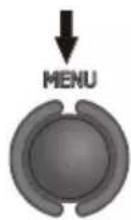
Press MENU.
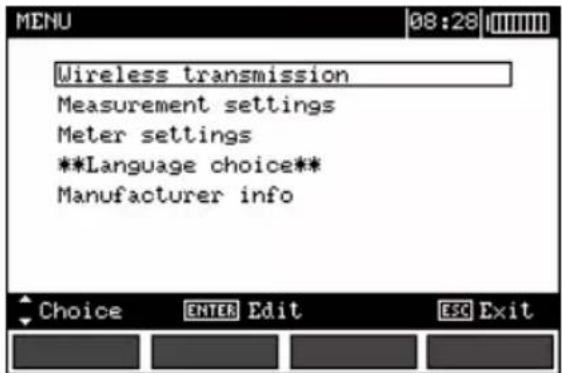
②
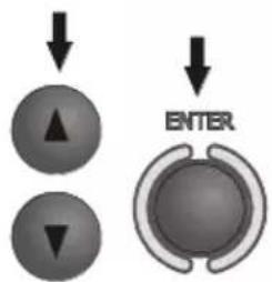
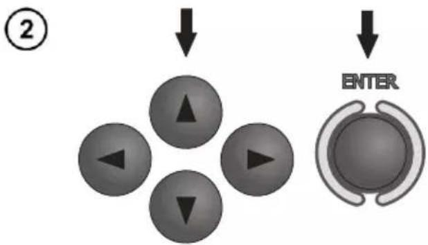
Using buttons ▲ and highlight the required position. Press ENTER to select the option.
2.1 Measurement settings
①
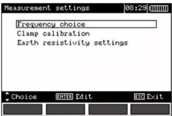
②
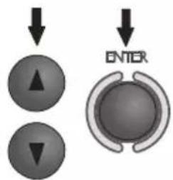
Using buttons and highlight the required position. Press ENTER to select the option.
2.1.1 Mains frequency
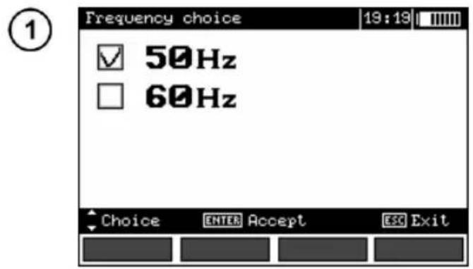
It is necessary to determine the frequency of the mains which is the source of potential interference in order to select the appropriate frequency of the measurement signal. Solely measurements based upon the correct frequency of the measurement signal will guarantee the optimum interference filtering. The meter is adapted for filtering of interference from 50 Hz and 60 Hz networks.
flowchart
graph TD
    A["●"] --> B["▲"]
    C["●"] --> D["▼"]
    E["●"] --> F["ENTER"]
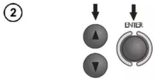
Using buttons ▲ and ▼ select the frequency and press ENTER to select the option.
2.1.2 Calibration of the measurement clamp C-3
The clamp bought apart for a meter that was purchased before must be calibrated before it is used for the first time. It may be periodically calibrated in order to avoid the influence of the ageing elements upon the resolution of measurements. The procedure of calibration must be realized also after clamp has been replaced.
Having read the preliminary information ENTER.
② Follow the displayed instructions.
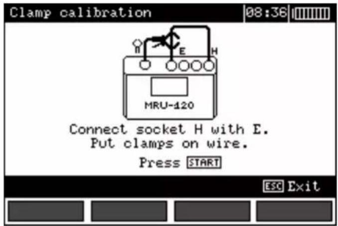
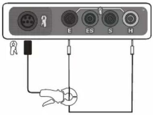

Once the calibration has been successfully concluded, The following will be displayed.
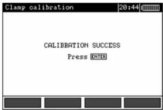
The meter has determined the correction factor for connected clamp. The factor is saved in the memory also when the power supply of the meter is off until the following successful calibration of the clamp has been performed.
Notes:
- Make sure the test lead passes centrally through the clamp.
Additional information displayed by the meter
| Message | Cause | Procedure |
| ERROR: CLAMP NOT CONNECTED OR NOT PUT ON WIRE CONNECTED TO H AND E SOCKET! CALIBRATION ABORTED.PRESS ENTER | The clamp is not connected | Check whether the clamp is connected to the device or whether it is placed upon the test lead used by the meter to force the passage of current. |
| ERROR: WIRE NOT CONNECTED TO H AND E TERMINAL! CALIBRATION ABORTED.PRESS ENTER | No wire | Revise the connections |
| ERROR: CALIBRATION COEFFICIENT OUT OF RANGE.CALIBRATION ABORTED.PRESS ENTER | Incorrect calibration factor | Check the quality of the connections and/or replace the clamp. |
2.1.3 Earth resistivity settings
![Earth resistivity settings 08:42 Result unit Distance unit ✓ [Ωm] ✓ [m] □ [Ωft] □ [ft] Choice ENTER Accept ESC Exit](/content/2026/05/851926/images/451bd508aac0eee06cb83c079c492ce611317c259b49393f9a22677138d634e3.jpg)
flowchart
graph TD
    A["Input Button 1"] --> B["Control Unit"]
    C["Input Button 2"] --> B
    D["Input Button 3"] --> B
    E["Input Button 4"] --> B
    F["Center"] --> G["OUTPUT"]
    style G fill:#ccc,stroke:#333,stroke-width:2px
Using buttons ▲, ▼ ◀ and ▶ select the result and the distance unit and press ENTER to confirm.
2.2 Meter settings
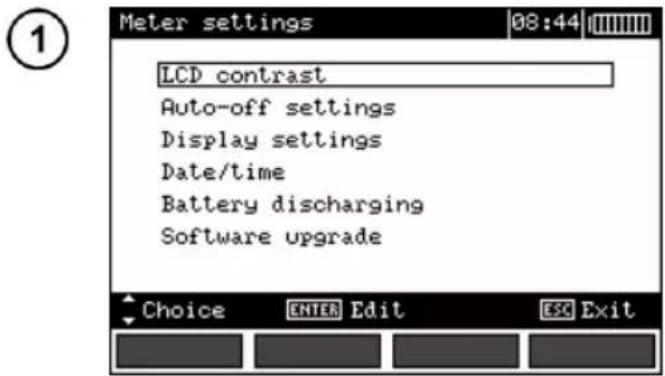
flowchart
graph TD
    A["▲"] --> B["▼"]
    C["ENTER"] --> D["○"]
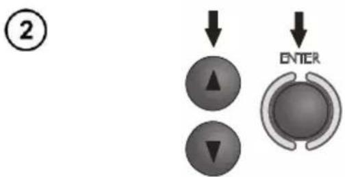
Using buttons ▲ select required item. Press ENTER to confirm.
2.2.1 LCD contrast
Using the buttons and set the contrast value and press ENTER.
2.2.2 AUTO-OFF settings
The setting determines the time before the automatic turning-off of the device when it is not in use. Use buttons and to set the time or AUTO-OFF disable, press ENTER.
2.2.3 Display settings
The setting permits to turn on/off the setting bar display. Use buttons and to set the display of the setting bar (measurement parameters), press ENTER.
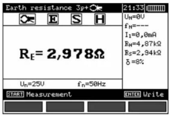
Visible bar
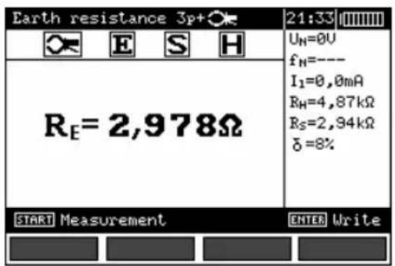
Hidden bar
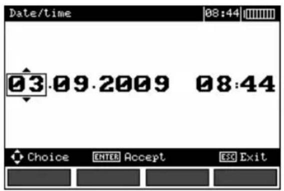
2.2.4 Date and time
①
②
③
Use buttons ◀ and ▶ to select the value to be modified (Day, month, hour, minute).
Use buttons ▲ and ▼ to set the value. Once the date and time have been set, press ENTER.
2.2.5 Battery discharging
The procedure is fully described in chapter 6.4.
2.2.6 Program update
NOTE! Before you proceed to programming, charge the accumulators. During programming do not turn the meter off or disconnect the transmission cable.
Before you proceed to updating the programme, download from the manufacturer's web page (www.sonel.pl) the meter programming software, install it in the computer and connect the meter to the computer.
Having chosen the Program update in the MENU, proceed in accordance with the instructions displayed by the programme.
2.3 Language choice
- Use buttons ▲ and ▼ to select **Language choice** in the main MENU and press ENTER.
- Use buttons and to select the language and press ENTER.
2.4 Information on the manufacturer
Use buttons ▲ and ▼ in order to select Product info and press ENTER.
3 Measurements
Note:
During measurements the status bar is displayed.
3.1 Measurement of resistance of earth connection and equipotential bonding (2P)
Note:
The measurement complies with the requirements specified in the standard EN 61557-4 (U<24 V, I>200 mA for R≤10 Ω).
①
natural_image
Circular mechanical component with a downward arrow and labeled point (no text or symbols beyond basic markings)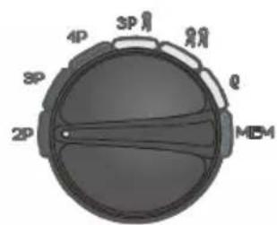
Turn the meter on. Set the rotational function selector at 2P.
②
Connect the object being measured to the terminals S and E of the meter.
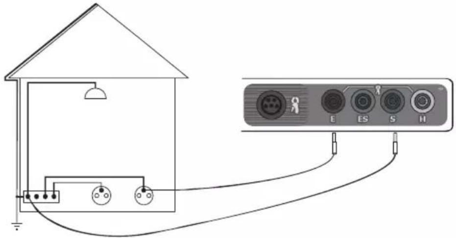
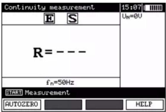
The meter is ready for measurement. The auxiliary display shows the value of the interference voltage and its frequency. The setting bat shows the mains frequency set in the MENU.
③

Press START In order for the test to commence.
④
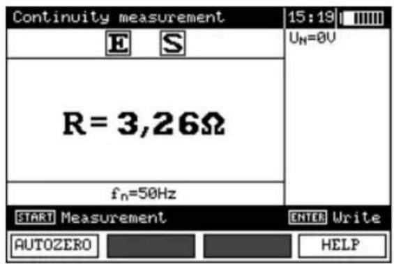
Read out the result.
The result is displayer for 20 s. It may be displayed again ENTER is pressed.
Additional information displayed by the meter
| R>20,0kΩ | Measurement range exceeded. |
| UN>40V! and a continuous sonic signal ^1 | The voltage on the measurement points exceeds 40 V, the measurement is blocked. |
| UN>24V! | The voltage on the measurement points exceeds 24 V but lower than 40 V, the measurement is blocked. |
| NOISE! | The value of the interfering signal is too high, the result may be distorted by additional uncertainty. |
3.2 Calibration of the test leads
In order to eliminate the influence of the resistance of the test leads over the result of the measurement, it is possible to realise its compensation (auto-zeroing). In order to do so the measurement function 2P includes the AUTOZERO subfunction.
3.2.1 Auto-zeroing on
①
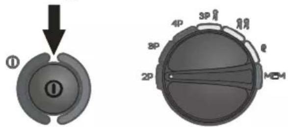
Turn the meter on. Set the rotational function selector at 2P.
②
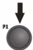
Press F1.
③
Follow the displayed instructions.
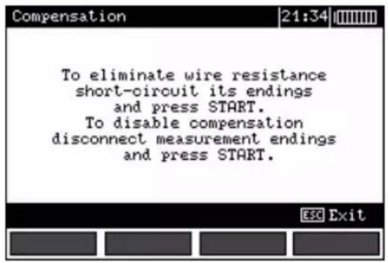
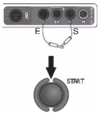
④
Once the auto-reset function Has concluded the following will be displayed:
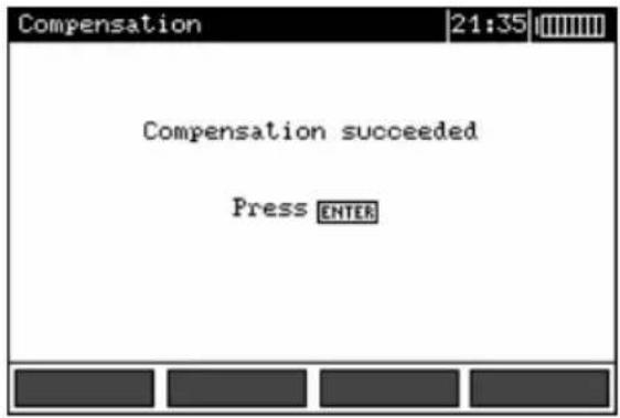
Auto-zeroing is signalled by the legend AUTOZERO on the right-hand side of the display.
3.2.2 Auto-zeroing off
①
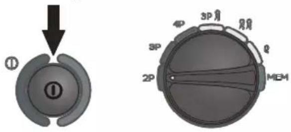
Turn the meter on. Set the rotational function selector at 2P.
②
Press F1.
③
Separate the test leads. Press START.
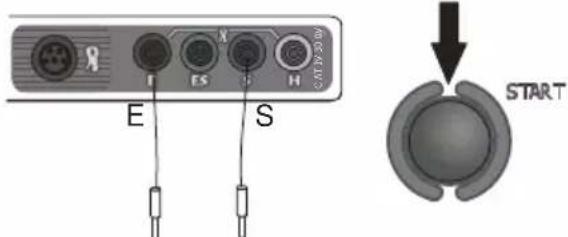
Once the auto-zeroing function has been turned off, the legend AUTOZERO will be no longer displayed.
Note:
- It is sufficient to realise compensation once for the given test leads. It is also remembered once the meter has been turned off.
3.3 Earth resistance measurement with 3-pole method (R E3P)
The basic kind of the earth resistance measurement is 3-pole measurement.
① Disconnect the tested earth electrode for the object installation.
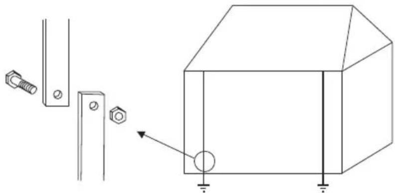
natural_image
Technical line drawing of a mechanical assembly with bolts and a 3D box (no text or symbols)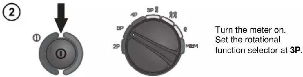
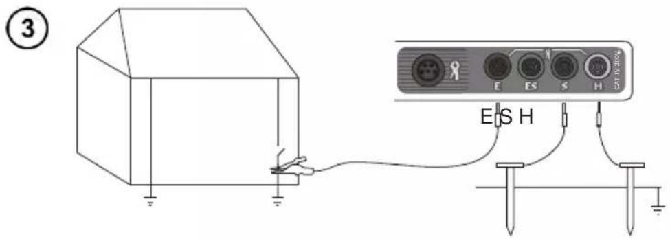
Connect the current electrode driver into ground to the H socket of the meter.
Connect the voltage electrode driver into ground to the S socket of the meter.
Connect the tested earth electrode to the E socket of the meter.
The tested earth electrode as well as the current electrode and voltage electrode should be aligned.
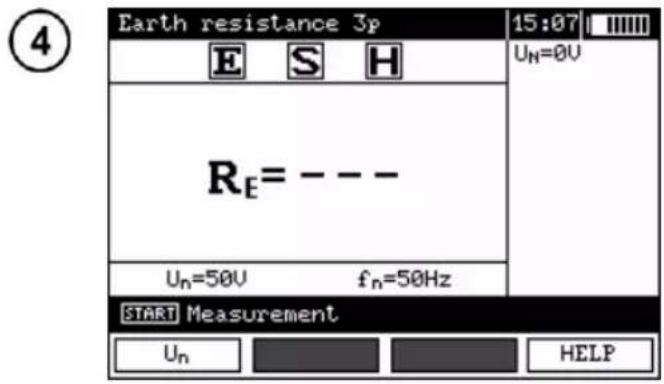
The meter is ready for measurement. The auxiliary display shows the value of the interference voltage and its frequency. The setting bar shows the mains frequency set in the MENU.
⑤
Press F1 to order to modify the measuring voltage.
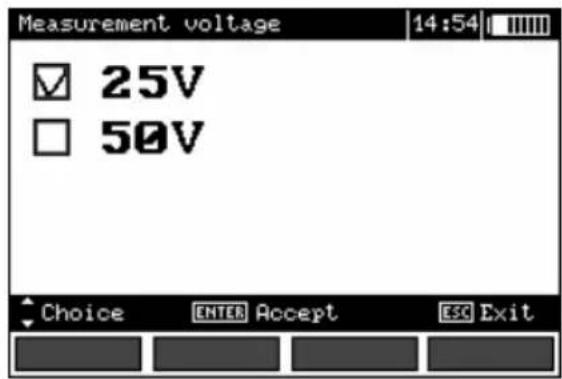
⑥
Use buttons and to set the measuring voltage and press ENTER.
⑦
Press START In order for the test to commence measurement.
⑧
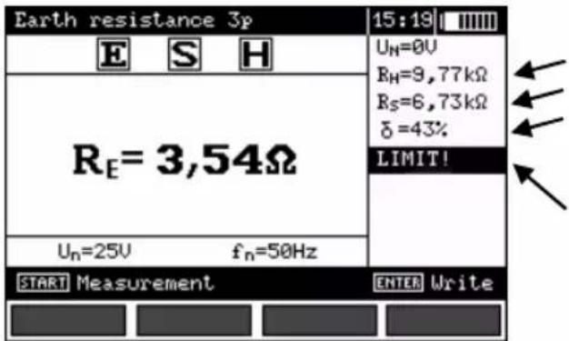
Read out the result.
Current electrode resistance
Voltage electrode resistance
Additional uncertainty caused by the resistance of the electrodes
Displayed, when >30%
The result is displayer for 20 s. It may be displayed again ENTER is pressed.
⑨
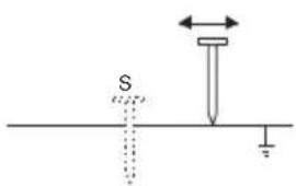
Repeat the measurements (see points 3, 7 and 8) moving the voltage electrode by a couple of meters: approaching it to and moving it away from the tested earth electrode.
If the R_E test results differ more than 3%, then it is necessary to increase significantly the distance between the current electrode from the earth electrode in question and repeat the measurement.
Note:

Earth resistance measurement may be realised if the interference voltage does not exceed 24 V. The interference voltage is measured up to 100 V. Do not connect the meter to a voltage exceeding 100 V.
- Pay particular attention to the quality of the connection of the tested object with the test leads – the contact area must be cleaned of paint, rust, etc.
- If the resistance of the auxiliary electrodes is too high, then the measurement of the R _E earth electrode will be distorted by additional uncertainty. A particularly high measurement uncertainty is generated if we measure a low value of the earth resistance with electrodes of a weak contact with the ground (such a situation occurs often if the earth electrode is properly made and the upper layer of the ground is dry and characterised by a low conductivity). Then the relation between the electrode resistance and the resistance of the measured earthing is very high, and so is the case of the measurement uncertainty which depends on it. What may be done then is to perform, in accordance with the formulae specified in point 10.2, calculations, which will permit to evaluate the influence of the measurement conditions. It is also possible to improve the contact of the electrode with the ground, for example by means of moistening of the place when the electrode is driven, its driving into the ground in another place or using a 80-centimetre electrode. Check also the test leads and make sure the insulation is not damaged and the contacts: test lead – banana plug – electrode are not corroded or loosened. In most cases the achieved resolution of the measurement is sufficient, but it is necessary to be conscious of the uncertainty the measurement is burdened with.
- If the resistance of H and S electrodes or one of them exceeds 19.9 kΩ, an appropriate message is displayed: "R_H and R_S electrodes resistance are higher than 19.9 kΩ! Measurement impossible!".
- Manufacturer's calibration doesn't include the resistance of test leads. Displayed result is sum of measured object and test leads resistance. However, in the meters up to No. 77, the factory calibration takes into account the resistance of only 2.2m leads.
Additional information displayed by the meter
| R_E>20,0k | Measurement range exceeded. |
| U_N>40V! and a continuous sonic signal ^1 | The voltage on the measurement points exceeds 40 V, the measurement is blocked. |
| U_N>24V! | The voltage on the measurement points exceeds 24 V but lower than 40 V, the measurement is blocked. |
| LIMIT! | The uncertainty of the electrode resistance >30%. (Uncertainties calculated on the basis of the measured values) |
| NOISE! | The value of the interfering signal is too high, the result may be distorted by additional uncertainty. |
3.4 Earth resistance measurement with 4-wire method (R E4P)
The 4-wire method is recommended in the case of measurements of earth resistance of very low values. It permits to eliminate the influence of the test leads resistance over the result of the measurement. In order to evaluate the resistance of the ground it is recommended to use the dedicated measurement function (point 3.9).
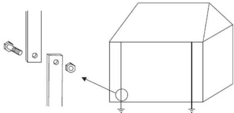
① Disconnect the tested earth electrode for the object installation.
natural_image
Technical line drawing of a mechanical assembly with bolts and a 3D box (no text or symbols)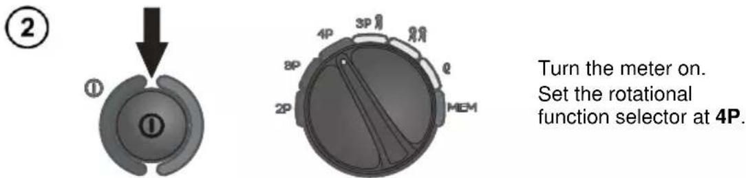
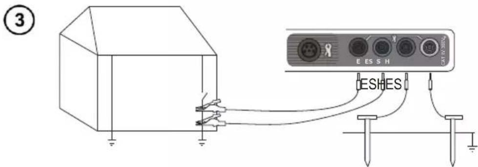
Connect the current electrode driver into ground to the H socket of the meter.
Connect the voltage electrode driver into ground to the S socket of the meter.
Connect the tested earth electrode to the E socket of the meter.
Connect the ES socket to the earth electrode below the E cable.
The tested earth electrode as well as the current electrode and voltage electrode should be aligned.
④
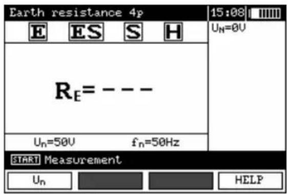
The meter is ready for measurement. The auxiliary display shows the value of the interference voltage and its frequency. The setting bar shows the mains frequency set in the MENU.
⑤
Press F1 to order to modify the measuring voltage.
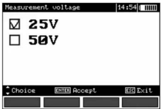
⑥
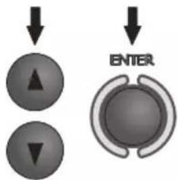
Use buttons and to set the measuring voltage and press ENTER.
⑦
Press START In order for the test to commence measurement.
⑧
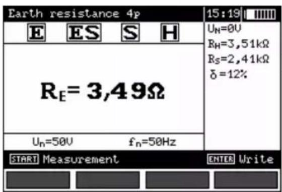

Read out the result. Current electrode resistance Voltage electrode resistance Additional uncertainty caused by the resistance of the electrodes
The result is displayer for 20 s. It may be displayed again ENTER is pressed.

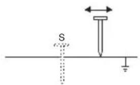
Repeat the measurements (see points 3, 7 and 8) moving the voltage electrode by a couple of meters: approaching it to and moving it away from the tested earth electrode. If the R_E test results differ more than 3%, then it is necessary to increase significantly the distance between the current electrode from the earth electrode in question and repeat the measurement.
Note:

Earth resistance measurement may be realised if the interference voltage does not exceed 24 V. The interference voltage is measured up to 100 V. Do not connect the meter to a voltage exceeding 100 V.
- Pay particular attention to the quality of the connection of the tested object with the test leads – the contact area must be cleaned of paint, rust, etc.
- If the resistance of the auxiliary electrodes is too high, then the measurement of the R _E earth electrode will be distorted by additional uncertainty. A particularly high measurement uncertainty is generated if we measure a low value of the earth resistance with electrodes of a weak contact with the ground (such a situation occurs often if the earth electrode is properly made and the upper layer of the ground is dry and characterised by a low conductivity). Then the relation between the electrode resistance and the resistance of the measured earthing is very high, and so is the case of the measurement uncertainty which depends on it. What may be done then is to perform, in accordance with the formulae specified in point 10.2, calculations, which will permit to evaluate the influence of the measurement conditions. It is also possible to improve the contact of the electrode with the ground, for example by means of moistening of the place when the electrode is driven, its driving into the ground in another place or using a 80-centimetre electrode. Check also the test leads and make sure the insulation is not damaged and the contacts: test lead – banana plug – electrode are not corroded or loosened. In most cases the achieved resolution of the measurement is sufficient, but it is necessary to be conscious of the uncertainty the measurement is burdened with.
- If the resistance of H and S electrodes or one of them exceeds 19.9 kΩ, an appropriate message is displayed: "R_H and R_S electrodes resistance are higher than 19.9 kΩ! Measurement impossible!".
Additional information displayed by the meter
| R_E>20,0k | Measurement range exceeded. |
| U_N>40V! and a continuous sonic signal | The voltage on the measurement points exceeds 40 V, the measurement is blocked. |
| U_N>24V! | The voltage on the measurement points exceeds 24 V but lower than 40 V, the measurement is blocked. |
| LIMIT! | The uncertainty of the electrode resistance >30%. (Uncertainties calculated on the basis of the measured values) |
| NOISE! | The value of the interfering signal is too high, the result may be distorted by additional uncertainty. |
3.5 Earth resistance measurement with 3-pole method with additional clamp ( R_E3P+C )
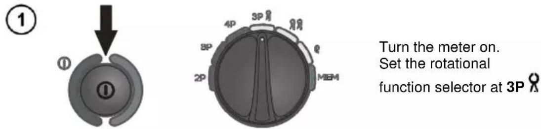
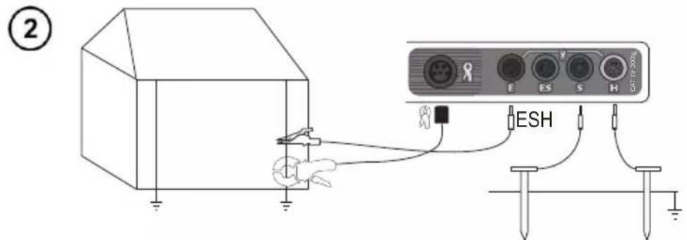
Connect the current electrode driver into ground to the H socket of the meter.
Connect the voltage electrode driver into ground to the S socket of the meter.
Connect the tested earth electrode to the E socket of the meter.
The tested earth electrode as well as the current electrode and voltage electrode should be aligned.
Snap the clamp on the tested earth electrode below the E cable connection.
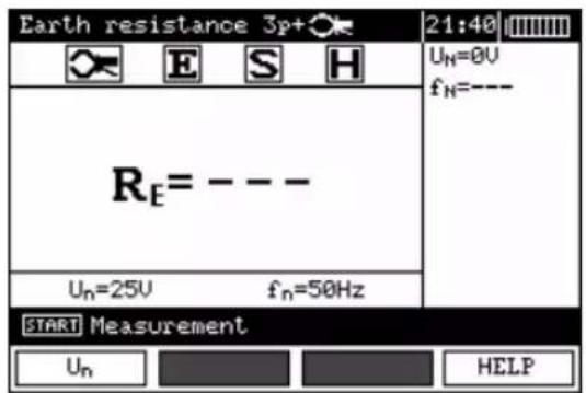
The meter is ready for measurement. The auxiliary display shows the value of the interference voltage and its frequency. The setting bar shows the mains frequency set in the MENU.
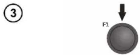
Press F1 to ordered to modify the measuring voltage.
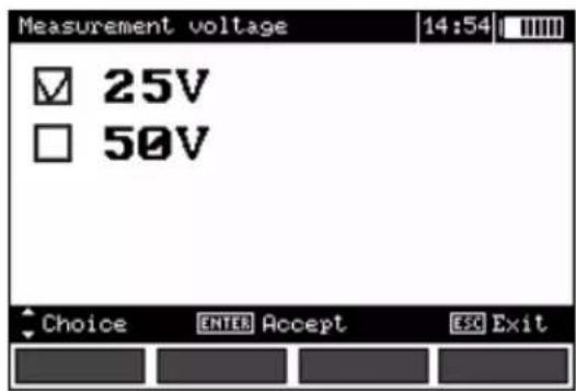
④
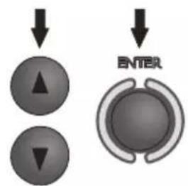
Use buttons and to set the measuring voltage and press ENTER.
⑤
Press START in order for the test to commence measurement.
⑥
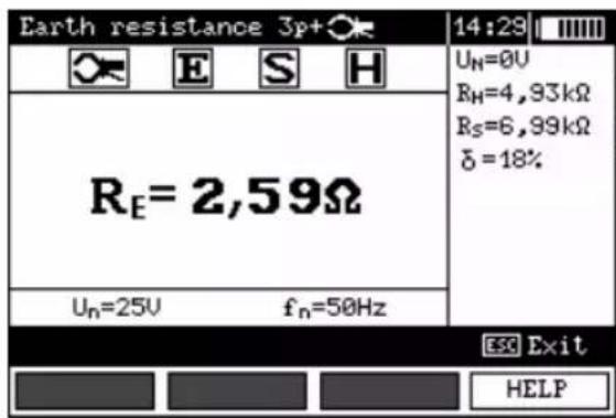
Read out the result. Current electrode resistance Voltage electrode resistance Additional uncertainty caused by the resistance of the electrodes.
The result is displayer for 20 s. It may be displayed again ENTER is pressed.
⑦
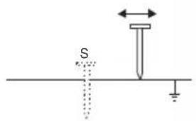
Repeat the measurements (see points 2 and 5) moving the voltage electrode by a couple of meters: approaching it to and moving it away from the tested earth electrode. If the R_E test results differ more than 3%, then it is necessary to increase significantly the distance between the current electrode from the earth electrode in question and repeat the gauging.
Notes:

Earth resistance measurement may be realised if the interference voltage does not exceed 24 V. The interference voltage is measured up to 100 V. Do not connect the meter to a voltage exceeding 100 V.
- The clamps are not the part of meter basic accessories, you have to purchase them apart.
- The clamp must be calibrated before it is used for the first time. It may be periodically calibrated in order to avoid the influence of the ageing elements upon the resolution of measurements. The clamp calibration option is in the MENU.
- Pay particular attention to the quality of the connection of the tested object with the test leads – the contact area must be cleaned of paint, rust, etc.
- If the resistance of the auxiliary electrodes is too high, then the measurement of the R _E earth electrode will be distorted by additional uncertainty. A particularly high measurement uncertainty is gen-
erated if we measure a low value of the earth resistance with electrodes of a weak contact with the ground (such a situation occurs often if the earth electrode is properly made and the upper layer of the ground is dry and characterised by a low conductivity). Then the relation between the electrode resistance and the resistance of the measured earthing is very high, and so is the case of the measurement uncertainty which depends on it. What may be done then is to perform, in accordance with the formulae specified in point 10.2, calculations, which will permit to evaluate the influence of the measurement conditions. It is also possible to improve the contact of the electrode with the ground, for example by means of moistening of the place when the electrode is driven, its driving into the ground in another place or using a 80-centimetre electrode. Check also the test leads and make sure the insulation is not damaged and the contacts: test lead – banana plug – electrode are not corroded or loosened. In most cases the achieved resolution of the measurement is sufficient, but it is necessary to be conscious of the uncertainty the measurement is burdened with.
- If the resistance of H and S probes or one of them exceeds 19.9 kΩ, an appropriate message is displayed: "R_H and R_S electrodes resistance are higher than 19.9 kΩ! Measurement impossible!".
- Manufacturer's calibration doesn't include the resistance of test leads. Displayed result is sum of measured object and test leads resistance.
Additional information displayed by the meter
| RE>2kΩ | Measurement range exceeded. |
| UN>40V! and a continuous sonic signal ^ | The voltage on the measurement points exceeds 40 V, the measurement is blocked. |
| UN>24V! | The voltage on the measurement points exceeds 24 V but lower than 40 V, the measurement is blocked. |
| NOISE! | The value of the interfering signal is too high, the result may be distorted by additional uncertainty. |
| LIMIT! | The uncertainty of the electrode resistance >30%. (Uncertainties calculated on the basis of the measured values) |
| IL>max | Excessive interfering current, the measurement error may exceed the basic error |
3.6 Earth resistance measurement with two-clamp method (2C)
Two-clamp measurements are applied where there is no possibility of using ground-driven electrodes.
NOTE! The two-clamp method may be used solely in the case of multiple earthing measurements.
①
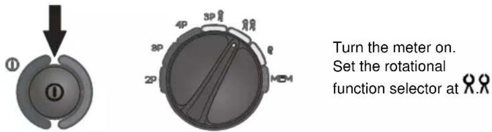
②
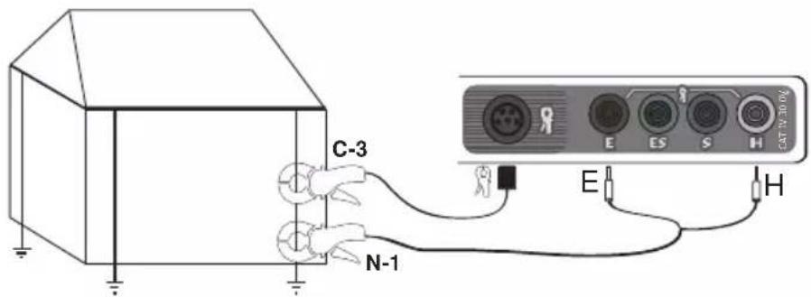
Connect the transmission clam to sockets H and E, while the measurements clamp should be connected to the clamp socket.
Snap the transmission clamp and measurement clamp on the tested earth electrode AT east 30 cm from each other.
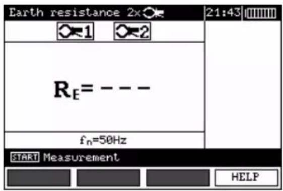
The meter is ready for measurement.
③
Press START In order for the test to commence measurement.

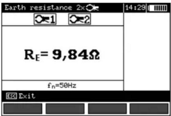
Read out the result.
The result is displayed for 20 s. It may be displayed again when ENTER is pressed.
Note:
Measurements may be performed in the presence of interference current not exceeding 3 A RMS and whose frequency complies with the value set in the MENU.
- The clamps are not the part of meter basic accessories, you have to purchase them apart.
- The clamp must be calibrated before it is used for the first time. It may be periodically calibrated in order to avoid the influence of the ageing elements upon the resolution of measurements. The clamp calibration option is in the MENU.
- If the clamp current is insufficient, an appropriate message is displayed: "Measured current is too low. Measurement impossible!".
Additional information displayed by the meter
| RE>150Ω | Measurement range exceeded. |
| UN>40V! and a continuous sonic signal<1> | The voltage on the measurement points exceeds 40 V, the measurement is blocked. |
| UN>24V! | The voltage on the measurement points exceeds 24 V but lower than 40 V, the measurement is blocked. |
| NOISE! | The value of the interfering signal is too high, the result may be distorted by additional uncertainty. |
3.7 Earth resistivity measurement ( )
For the purpose of earth resistivity measurements – which are used as a preliminary measure for the project of earthing systems or in geology – there is a separate function, which is selected by means of the rotational function selector: earth resistivity measurements . The function is metrologically identical as the 4-wire earth resistance measurement, but it includes an additional procedure of storing of the distance between the electrodes. The result of the measurement is the resistance value which is calculated automatically in accordance with the following formula: = 2 LR_E , which is used in the Wenner's measurement method. The method in question assumes equal distances between electrodes.
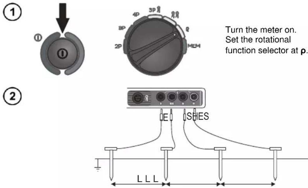
Turn the meter on.
Set the rotational
function selector at p.
Connect the four aligned and equally spacer electrodes, which are driven into the ground, to the meter, and do so In accordance with the diagram above
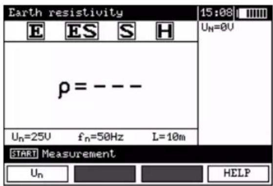
The meter is ready for measurement. The auxiliary display shows the value of the interference voltage and its frequency. The setting bar shows the measurement voltage, mains frequency set in the MENU and the distance between the electrodes.
③
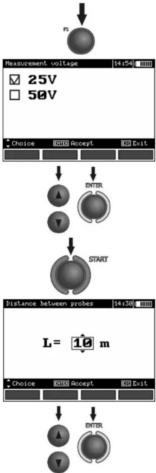
flowchart
graph TD
    A["Measurement voltage"] --> B{25V}
    A --> C{50V}
    B --> D["Choice"]
    C --> E["ENTER"]
    D --> F["Accept"]
    E --> G["Exit"]
    H["Distance between probes"] --> I["L = 10 m"]
    I --> J["Choice"]
    I --> K["ENTER"]
    J --> L["Accept"]
    K --> M["Exit"]
    N["Start"] --> O["ENTER"]
    P["End"] --> Q["ENTER"]
Press F1 to change the measurement voltage.
④
5
flowchart
graph TD
    A["Start"] --> B["ENTER"]
    B --> C["Two circular elements with directional arrows"]
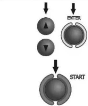
Use buttons and to set the measuring voltage and press ENTER.
Press START to commerce measurement. The meter will activate the mode of selection of the distance between probes.
⑥
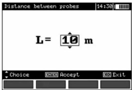
Use buttons and to set the distance between electrodes and press ENTER In order to commerce measurement.
⑦
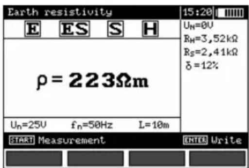

Read out the result. Current electrode resistance Voltage electrode resistance Additional uncertainty caused by the resistance of the electrodes
The result is displayer for 20 s. It may be displayed again ENTER is pressed.
Note:

Earth resistance measurement may be realised if the interference voltage does not exceed 24 V. The interference voltage is measured up to 100 V. Do not connect the meter to a voltage exceeding 100 V.
- Calculations are based upon the assumption that the distances between the specific measurement electrodes are equal (the Wenner's method). If this is not the case the earthing resistance measurement must be realised by means of the 4-wire method and calculations must be performed individually.
- Pay particular attention to the quality of the connection of the tested object with the test leads – the contact area must be cleaned of paint, rust, etc.
- If the resistance of the auxiliary electrodes is too high, then the measurement of the R _E earth electrode will be distorted by additional uncertainty. A particularly high measurement uncertainty is generated if we measure a low value of the earth resistance with electrodes of a weak contact with the ground (such a situation occurs often if the earth electrode is properly made and the upper layer of the ground is dry and characterised by a low conductivity). Then the relation between the electrode resistance and the resistance of the measured earthing is very high, and so is the case of the measurement uncertainty which depends on it. What may be done then is to perform, in accordance with the formulae specified in point 10.2, calculations, which will permit to evaluate the influence of the measurement conditions. It is also possible to improve the contact of the electrode with the ground, for example by means of moistening of the place when the electrode is driven, its driving into the ground in another place or using a 80-centimetre electrode. Check also the test leads and make sure the insulation is not damaged and the contacts: test lead – banana plug – electrode are not corroded or loosened. In most cases the achieved resolution of the measurement is sufficient, but it is necessary to be conscious of the uncertainty the measurement is burdened with.
- If the resistance of H and S probes or one of them exceeds 19.9 kΩ, an appropriate message is displayed: "R_H and R_S electrodes resistance are higher than 19.9 kΩ! Measurement impossible!".
Additional information displayed by the meter
| ρ >1MΩm | Measurement range exceeded. |
| UN>40V! and a continuous sonic signal | The voltage on the measurement points exceeds 40 V, the measurement is blocked. |
| UN>24V! | The voltage on the measurement points exceeds 24 V but lower than 40 V, the measurement is blocked. |
| LIMIT! | The uncertainty of the electrode resistance >30%. (Uncertainties calculated on the basis of the measured values) |
| NOISE! | The value of the interfering signal is too high, the result may be distorted by additional uncertainty. |
4 Memory
The MRU-120 meters are equipped with a memory whose capacity is 990 results of resistance measurements. Individual measurements are saved in memory cells. The whole memory is divided into 10 banks with 99 cells each. Each result may be saved in a cell of a defined number and in the selected bank, so the user of the meter may, at their own discretion assign numbers of the cells to individual measurement points and the numbers of the banks to individual objects, realize measurements in any order and repeat them without loosing other data.
The memory of the results of the measurements is not deleted when the meter is turned on, so they may be read further on or transmitted to the computer. The number of the current cell and the bank is not modified either.
It is recommended to delete the memory once the data have been read or before a new series of measurements is realized. New measurements may be saved in the same cells as the previous ones.
4.1 Saving of the measurement results in the memory
①
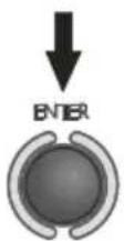
Once the measurement has finished press ENTER.
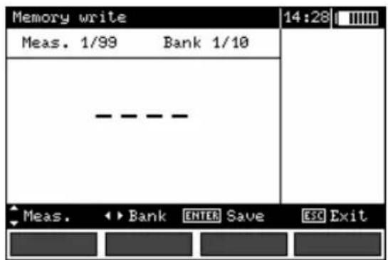
Empty cell
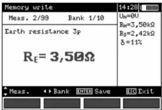
Occupied cell
②
Selection of the measure (cell) is realized by means of the buttons ▲ and ▼. Bank may be selected with the buttons ◀ and . ► To save press ENTER.
③
Should you intend to save data In an occupied cell, the following message will be displayed:
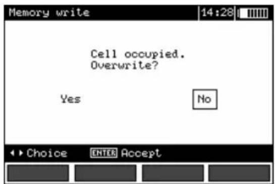
④
Once the option has been selected with the buttons ◀ and ▶ press ENTER.
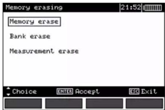
4.2 Memory erasing
Note:
- During the process of memory erasing the progress bar is being displayed.
①
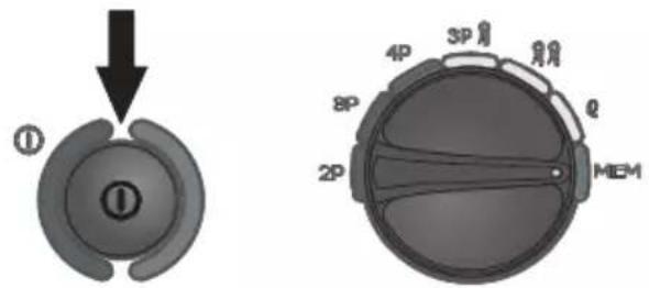
Turn the meter on.
Set the rotational
function selector at MEM.
②
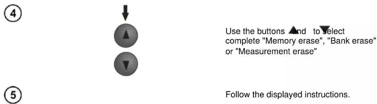
Using the buttons
and highlight
"Memory erasing".
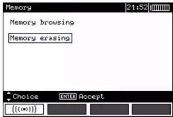
③
Press ENTER.
4.3 Memory browsing
flowchart
graph TD
    A["①"] --> B["▲"]
    B --> C["▼"]
    C --> D["ENTER"]
    E["②"] --> F["Press ENTER."]
    G["Use the buttons and to highlight "Memory browsing"."] --> H["→"]
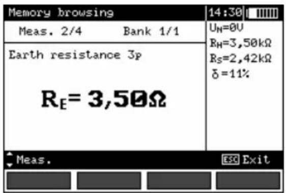
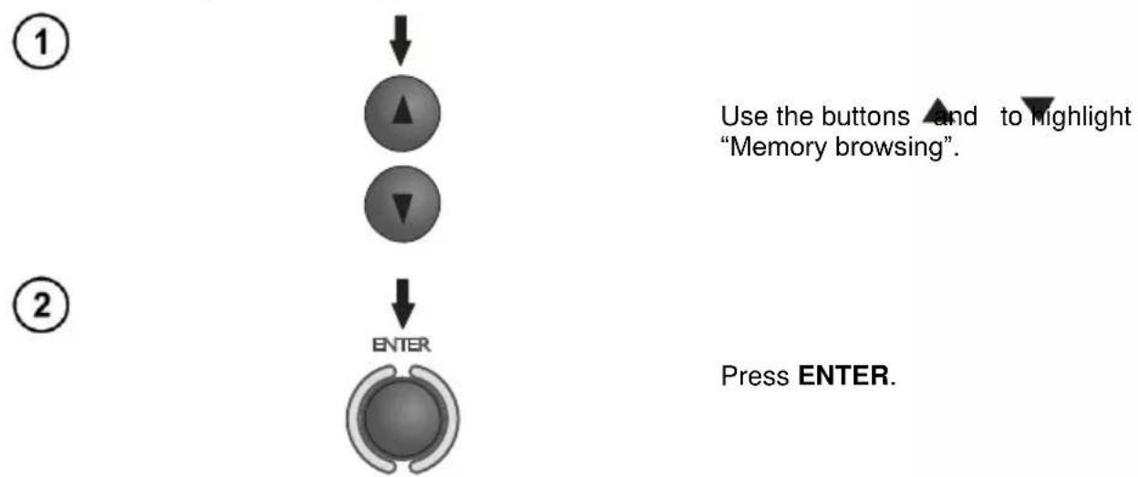
③ Use the buttons and to select bank and the buttons and to select a cell.
Note:
- During a memory search empty cells and banks are unavailable. „Meas. 1/20” means the first measurement in a group of 20; cells 21...99 are empty and unavailable. The same principle refers to banks. If the memory is not filled in a continuous manner, then empty measurements and banks are skipped during browsing.
5 Data transmission
Remarks:
- Data transmission is not possible during the charging of accumulators.
5.1 Computer connection accessories
What is necessary in order to operate the meter with a computer is additional accessories, namely a USB cable and appropriate software. If the required accessories such have not been purchased along with the meter, then they are available from the manufacturer or an authorised distributor.
The accessories may be used in case of many devices manufactured by SONEL S.A. which are equipped with the USB interface.
Detailed information regarding software is available from the manufacturer or an authorised distributor.
5.2 Connection of the meter to a computer
- Set the rotational function selector at MEM.
- Connect the cable to the USB port of the computer and the USB socket of the meter.
- Start the programm.
6 Power supply
Note:
Instrument MRU-120 has been designed for use only with the supplied rechargeable batteries. Using disposable instead of rechargeable batteries can take place only in emergency cases (e.g. total discharge of batteries during field measurements of electric poles). However, a rapid discharge of disposable batteries (several measurements) and malfunction of the instrument at high instantaneous power consumption should be expected.
6.1 Monitoring of the power supply voltage
The level of the charge of the batteries or accumulators is currently indicated by the symbol in the right upper corner of the display:
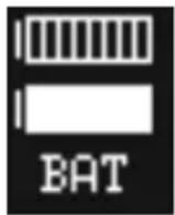
Battery charged.
Battery low.
Battery fully discharged.
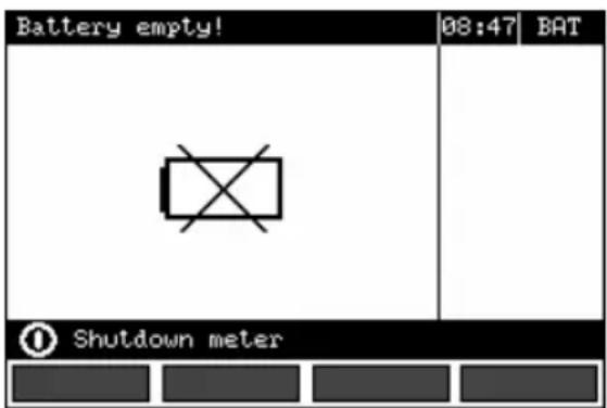
Battery fully discharged, Measuring blocked.
Note:
- The displayed BAT symbol means insufficient power supply voltage and the need to charge the accumulators.
- Measurements realized with an insufficient meter power supply voltage are distorted with additional errors which are impossible to ascertain by the user and thus they cannot constitute a basis for a conclusion of correctness of the tested earthing system.
6.2 Replacement of accumulators
The MRU-120 meter is equipped with a package of NiMH accumulators and charger.
The package of accumulators is placed in a compartment. The charger is installed inside the meter casing and it may be used solely to charge the original accumulators. It is powered from an external power supply. It is also possible to use a car lighter socket.
WARNING:
If the test leads are left in the sockets during replacement of the batteries or the package of accumulators, there is a risk of electric shock with a dangerous voltage.
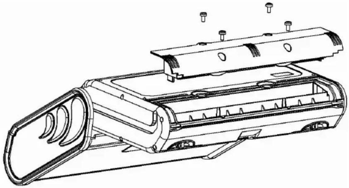
In order to replace the package of accumulators it is necessary to do the following:
- Remove all the test leads from the sockets and turn the meter off,
- Remove the four screws of the accumulators/batteries compartment (in the lower part of the casing),
- Remove the compartment,
- Insert the compartment in the meter,
- Replace the four screws of the accumulators/batteries compartment.
natural_image
Technical line drawing of a mechanical device with multiple ports and internal components (no text or symbols)NOTE!
Do not use the meter when the accumulator compartment is removed or open or power it from other sources than those mentioned in the present manual.
6.3 Fuse replacement
Remove the battery compartment to get access to two replaceable fuses:
- FST 1 A 250 VAC, 5x20 mm and
- 2 A 250 VAC, time-delay fuse, 5x20 mm.
If the instrument or battery charger does not work, before sending it for servicing, check the fuses and, if they are blown, replace them with identical ones. The fuses are placed in holders, near the centre of the cavity. To remove the fuses, use a narrow tool (e.g. a screwdriver).
6.4 Charging of accumulators
Charging commences once the power supply has been connected to the meter regardless of the fact whether the meter is on or off. During charging the screen looks as it is presented in the following illustration. The accumulators are charged in accordance with the algorithm of „quick charge” – this process permits to reduce the duration of charging to approximately four hours. The end of the process of charging is signalled by: Charge in progress. In order to turn the device off, remove the power supply plug of the charger.
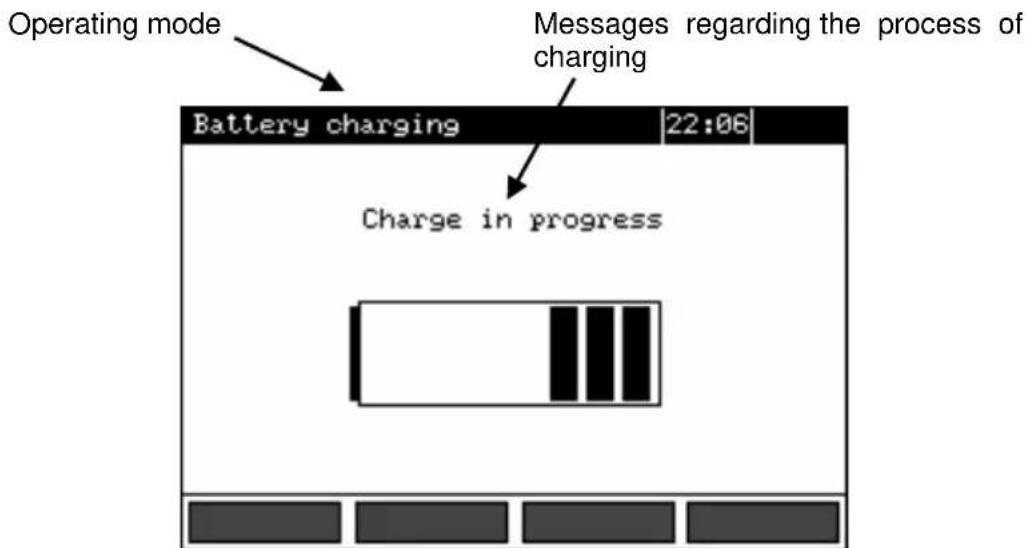
Charging Progress, the changing interior symbolizes charging.
Note:
- As a result of interferences in the network it is possible that the process of charging of accumulators will finish too fast. In the case too short a time of charging is detected it is necessary to remove the plug of the charger and start charging anew.
Additional information displayed by the meter
| Message | Cause | Proceeding |
| Battery connection error! | Excessive voltage at the accumulator package during charging. | Check the contacts of the accumulator package. Should the problem persist, replace the package. |
| No battery! | No communication with the accumulator controller or batteries compartment put in. | Check the contacts of the accumulator package. Should the problem persist, replace the package. Put the accumulators compartment instead of batteries. |
| Battery temperature too low! | The ambient temperature is lower than 10°C | It is not possible to charge the accumulators correctly in such a temperature. Place the meter in a warm place and commence the charging mode anew. The present message may be displayed also in the case of deep discharging of the accumulators. It is then recommended to try to turn the charger on and off repeatedly. |
| Precharge error | A damaged or deeply discharged accumulator package | The message is displayed for a while and then the precharge process begins again. If after several attempts the message: Battery temperature too high! is displayed, replace the package. |
6.5 Discharging of accumulators
In order to guarantee proper functioning of the accumulators (charge indications) and prolong their durability, it is recommended to charge them from zero from time to time. Proceed as follows in order to discharge the accumulators:
①
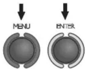
Press MENU and highlight Meter settings. Press ENTER.
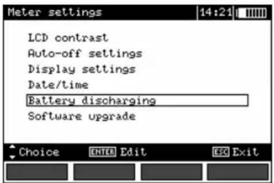

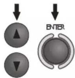
Use buttons and to select Battery discharging, and press ENTER.
Read the displayed text and accept.
Discharging, which may last up to 10 hours depending on the level of the charge of the package, is signalled with the following message: Discharging of accumulators in progress.
6.6 General principles regarding using Ni-MH accumulators
- If you do not use the device for a prolonged period of time, then it is recommended to remove the accumulators and store them separately.
- Store the accumulators in a dry, cool and well ventilated place and protect them from direct sunlight. The temperature of the environment in the case of prolonged storage should not exceed 30^ C. If the accumulators are stored for a long time in a high temperature, then the occurring chemical processes may reduce their lifetime.
- Accumulators Ni-MH resist normally 500-1000 charging cycles. The accumulators reach their maximum capacity after being formatted (2-3 charge and discharge cycles). The most important factor which influences the lifetime of an accumulator is the depth of discharge. The deeper the discharge of the accumulator, the shorter its lifetime.
- The memory effect is limited in the case of Ni-MH accumulator. These accumulators may be charged at any point with no serious consequences. However, it is recommended to discharge them completely every few cycles.
- During storage of Ni-MH accumulators they are discharged at the rate of approximately 30% per month. Keeping accumulators at high temperatures may accelerate this process even 100%. In order to prevent excessive discharge of accumulators, after which it would be necessary to format them, it is recommended to charge the accumulators from time to time (even if not in use).
- Modern fast chargers detect both too low and too high a temperature of accumulators and react to the situation adequately. Too low a temperature should prevent the start of the process of charging, which might damage the accumulator irreparably. An increase of the temperature of the accumulator is a signal to stop charging and is a typical phenomenon. However charging at a high temperature of the environment apart from reducing the lifetime causes an accelerated increase of the temperature of the accumulator, which will be not charged to its full capacity.
- Remember that in the case of quick charging accumulators are charged to approximately 80% of their capacity; better results may be obtained if the process of charging is continued: the charger goes then to the phase of charging with a low current and after next couple of hours the accumulators are charged to their full capacity.
- Do not charge or use accumulators in extreme temperatures. Extreme temperatures reduce the lifetime of batteries and accumulators. Avoid placing devices powered from accumulators in very hot environments. The nominal working temperature must be absolutely observed.
7 Cleaning and maintenance
NOTE!
Apply solely the maintenance methods specified by the manufacturer within the present manual.
The casing of the meter may be cleaned with a soft, damp cloth using all-purpose detergents. Do not use any solvents or cleaning agents which might scratch the casing (powders, pastes, etc.).
Clean the auxiliary electrode with water and dry it. Before the electrode is stored for a prolonged period of time it is recommended to grease it with any machine lubricant.
The reels and test leads should be cleaned with water and detergents, and then dried.
The electronic system of the meter does not require maintenance.
8 Storage
- In the case of storage of the device, the following recommendations must be observed:
- Disconnect all the test leads from the meter.
- Clean the meter and all its accessories thoroughly.
- Wind the long test leads onto the reels.
- In the case the meter is to be stored for a prolonged period of time, the batteries must be removed from the device.
- In order to prevent a total discharge of the accumulators in the case of a prolonged storage, charge them from time to time.
9 Dismantling and disposal
Worn-out electric and electronic equipment should be gathered selectively, i.e. it must not be placed with waste of another kind.
Worn-out electronic equipment should be sent to a collection point in accordance with the law of worn-out electric and electronic equipment.
Before the equipment is sent to a collection point, do not dismantle any elements.
Observe the local regulations concerning disposal of packages, worn-out batteries and accumulators.
10 Technical data
- The abbreviation „m.v.” in the accuracy definition means the measured value.
10.1 Basic data
Interference voltage measurement U_N (RMS)
| Range | Resolution | Accuracy |
| 0...100 V | 1 V | ±(2% m.v. + 3 digits) |
• measurement for f N 45...65 Hz
- frequency of measurements – minimum two measurements/s
Measurement of resistance of protective conductors and equipotential bonding (2P)
The measurement method: in accordance with IEC 61557-4
Range of measurement in accordance with IEC 61557-4: 0,24 Ω ... 19,9 kΩ
| Range | Resolution | Accuracy |
| 0,00...19,99 Ω | 0,01 Ω | ±(2% m.v. + 2 digits) |
| 20,0...199,9 Ω | 0,1 Ω | |
| 200...1999 Ω | 1 Ω | |
| 2,00...9,99 kΩ | 0,01 Ω | ±(5% m.v. + 2 digits) |
| 10,0...19,9 kΩ | 0,1 kΩ |
Measurement of earth resistance - 3-pole method (RE3P), 4-wire method (RE4P)
The measurement method: 3-pole, in accordance with IEC 61557-5
Range of measurement in accordance with IEC 61557-5: 0,30 Ω ... 19,9 kΩ
| Range | Resolution | Accuracy |
| 0,00...19,99 Ω | 0,01 Ω | ±(2% m.v. + 2 digits) |
| 20,0...199,9 Ω | 0,1 Ω | |
| 200...1999 Ω | 1 Ω | |
| 2,00...9,99 kΩ | 0,01 kΩ | ±(5% m.v. + 4 digits) |
| 10,0...19,9 kΩ | 0,1 kΩ |
Measurement of resistance of auxiliary electrodes R_H and R_S
| Range | Resolution | Accuracy |
| 0...999 Ω | 1 Ω | ±(5% (RE+RH+RS) + 8 digits) but not less than 10% RE |
| 1,00...9,99 kΩ | 0,01 kΩ | |
| 10,0...19,9 kΩ | 0,1 kΩ |
Measurement of earth resistance - 3-pole method with additional clamp (R _E 3P+C)
Range of measurement in accordance with IEC 61557-5: 0,44 Ω ... 1999 Ω
| Range | Resolution | Accuracy |
| 0,00...19,99 Ω | 0,01 Ω | ±(8% m.v. + 3 digits) |
| 20,0...199,9 Ω | 0,1 Ω | |
| 200....1999 Ω | 1 Ω |
Measurement of multiple earth resistance - two-clamp method (2C)
| Range | Resolution | Accuracy |
| 0,00...19,99 Ω | 0,01 Ω | ±(10% m.v. + 3 digits) |
| 20,0...149,9 Ω | 0,1 Ω | ±(20% m.v. + 3 digits) |
Earth resistivity measurement (ρ)
The measurement method: Wenner's, = 2 LR_E
| Range | Resolution | Accuracy |
| 0,0..199,9 Ωm | 0,1 Ωm | Depends on the basic uncertainty of the R _E 4P measurement but not less than ±1 digit. |
| 200..1999 Ωm | 1 Ωm | |
| 2,00..19,99 kΩm | 0,01 kΩm | |
| 20,0..99,9 kΩm | 0,1 kΩm | |
| 100..999 kΩm | 1 kΩm |
• distance between measurement electrodes (L): 1...50 m
Other technical data
a) type of insulation in accordance with EN 61010-1 and IEC 61557.....double
b) measurement category in accordance with EN 61010-1 (for 2000 m a.s.l.) IV 300 V
c) protection grade of the casing in accordance with EN 60529....IP54
d) maximum interference voltage AC + DC at which a measurement may be performed....24 V
e) maximum measured interference voltage....100 V
f) maximum interference current at which a measurement of the earth resistance by means of the clamp method is performed....3 A RMS
g) frequency of the measurement current
- for 50 Hz mains ....125 Hz
- for 60 Hz mains ....150 Hz
h) measurement voltage and current for 2P....U < 24 V RMS, I ≥ 200 mA for R ≤ 60 Ω
i) measurement voltage for R E 3P, R E 4P ....25 or 50 V
j) measurement current (short-circuit current) for R E 3P, R E 4P....>200 mA
k) maximum resistance of measurement electrodes.... 20 kΩ
I) signalling of insufficient clamp current for ....≤0.5 mA
m) power supply of the meter ...... accumulator package type SONEL NiMH 4.8 V 3 Ah
n) parameters of AC adapter for the battery charge....100 V...240 V, 50 Hz...60 Hz
o) number of measurements for 2P ....>1100 (1 Ω, 2 measurement/min)
p) number of measurements for R_E3P , R_E4P>800 ( R_E=10 , R_H=R_S=100 , 2 measurement/min)
q) duration of a resistance measurement by means of the two-pole method ....<6 s
r) duration of a resistance and resistivity measurement by means of other methods ....<8 s
s) dimensions....288 x 223 x 75 mm
t) mass of the meter with accumulators ca. 2 kg
u) working temperature....-10..+50°C
v) temperature range suitable for initiating battery charging....+10°C to +40°C
w) temperatures at which loading is interrupted..... below +5 °C and above (or equal to) +50°C
x) reference temperature 23 ±2°C
y) storage temperature....-20...+80°C
z) relative humidity....20..90%
aa) relative humidity nominal 40..60%
bb) altitude (above sea level) .... ≤2000 m*
cc) quality standard ......design and production in accordance with ISO 9001
dd) the product meets EMC requirements according to the following standards .... EN 61326-1 and EN 61326-2-2
NOTE
\* Information about the use of meter at altitude from 2000 m to 5000 m
As for voltage inputs E, ES, S, H the instrument is to be considered downgraded to measurement category CAT III 300 V to ground (max 300 V between inputs) or CAT IV 150 V to ground (max 150 V between inputs). Markings and symbols indicated on the instrument are to be considered valid when using it at altitude lower than 2000 m.
10.2 Additional data
Data regarding additional uncertainties are useful mainly in the case the meter is used under non-standard conditions as well as for measurement laboratories for the purpose of calibration.
10.2.1 Influence of the serial interference voltage U_N upon earth resistance measurements for functions R_E3P , R_E4P , R_E3P+C
| R | Additional uncertainty [Ω] |
| 0,000...19,99 Ω | ± (25· 10^-4 · R_E + 2 · 10^-4 _NR_E) · U_N |
| >19,99 Ω | ± (5· 10^4 · R_E + 2 · 10^2) · U_N |
10.2.2 Influence of the serial interference voltage U_N upon earth resistance measurements for function
$$ \Delta_ {\mathrm{add}} [ \Omega ] = \pm 2, 5 \cdot (1 0 ^ {- 3} \cdot R _ {E} + 1 0 ^ {- 6} \cdot R _ {H} \cdot U _ {N}) \cdot U _ {N}, $$
$$ \text { where } R _ {E} = \frac {\rho}{2 \cdot \pi \cdot L} $$
10.2.3 Influence of the auxiliary electrodes upon earth resistance measurements for function R_E3P , R_E4P , R_E3P+C
| R_H,R_S | Additional uncertainty [%] |
| R_H≤ 1 k and R_S≤ 1 k | within the range of the basic uncertainty |
| R_H>1 k lub R_S>1 k lub R_H and R_S>1 k | ±(_SR_S+10^6·200+_H^2R_E· R_H+200·5·10^-3+R_H·4·10^-4) |
R_E[] , R_S[] and R_H[] are values which are displayed by the device.
10.2.4 Influence of the auxiliary electrodes upon earth resistance measurements for function
| Uncertainty [%] | ||
| ±( _H · (R_S + 30000)R_E | -7+··· | -4 · _H^2 + R_S^2 ) |
R_E[] , R_S[] and R_H[] are values which are displayed by the device.
10.2.5 Influence of the interference current I_1 upon the result of the earth resistance measurement for method R_E3P+C
The MRU-120 meter may perform a measurement, if the value of the interference current does not exceed 3 A RMS and the frequency complies with the value set in the MENU.
| R_E | U_wy | Uncertainty [Ω] |
| ≤50 Ω | 25 V | ± · ^-3 · R_E · I_l^2 |
| 50 V | ± (2,5·10-3· R_E · I_l^2 ) | |
| >50 Ω | 25 V | ± (70·10-6· R_E^2 · I_l^2 ) |
| 50 V | ± (50·10-6· R_E^2 · I_l^2 ) |
If the interference current exceeds 3 A the possibility of measurement is blocked.
10.2.6 Influence of interference current on the result of the earth resistance measurement for two-clamp method (2C)
The MRU-120 meter may perform a measurement, if the value of the interference current does not exceed 3 A RMS and the frequency complies with the value set in the MENU.
| RE | Uncertainty [Ω] |
| 0,00...4,99 Ω | within the range of the basic uncertainty |
| 5,00...19,9 Ω | ± (5 · 10^-3 · R_E^2 · I_I^3) |
| 20,0...149,9 Ω | ± (6 · 10^-2 · R_E^2 · I_I^3) |
If the interference current exceeds 3 A the possibility of measurement is blocked.
10.2.7 Influence of the relation of the resistance measured with clamp for the multiple earthing branch to the resultant resistance ( R_E3P+C )
| Rc | Uncertainty [Ω] |
| ≤99,9 Ω | ± (3 · 10^-3 · _CR_w^2) |
| >99,9 Ω | ± (6 · 10^-2 · _CR_w^2) |
R_c[] is the value of the resistance measured with clamps for the branch displayed by the device, and R_w[] is the value of the resultant multiple earth resistance.
10.2.8 Additional uncertainties in accordance with IEC 61557-4 (2P)
| Influencing factor | Symbol | Additional uncertainty |
| Location | E_1 | 0% |
| Power supply voltage | E_2 | 0% (BAT not displayed) |
| Temperature | E_3 | ±0,2digit/°C for R<1 kΩ±0,07%/°C ±0,2 digit/°C for R≥1 kΩ |
10.2.9 Additional uncertainties in accordance with IEC 61557-5 (R _E3P , RE4P, RE3P+C)
| Influencing factor | Symbol | Additional uncertainty |
| Location | E_1 | 0% |
| Power supply voltage | E_2 | 0% (BAT not displayed) |
| Temperature | E_3 | ±0,2 digit/°C for R<1kΩ ±0,07%/°C ±0,2 digit/°C for R≥ 1kΩ |
| Serial interference voltage | E_4 | In accordance with formula In 10.2.1 ( U_z=3 V 50/60 Hz ) |
| Resistance of electrodes and auxiliary earth electrodes | E_5 | In accordance with the formula in 10.2.3 |
11 Accessories
The current list of accessories can be found on the manufacturer's website.
11.1 Standard accessories
- auxiliary electrode, 30 cm (4 pcs.) – WASONG30
- cramp with banana socket – WAZACIMA1
- 2.2-metre black test lead with banana plugs at one end, with a test prod – WAPRZ2X2BLBB
- 25-metre blue (WAPRZ025BUBBSZ) and red (WAPRZ025REBBSZ) test leads (2 pieces) with banana plugs at both ends, wound upon reels which permit to elongate the test leads (for the purpose of measurements of extensive earthing systems)
WARNING: Test leads on spools are used only for measurements at voltages below 50 V. They must not be used for measurements in mains.
- 50-metre, yellow test lead wound upon a reel with banana plugs at both ends – WAPRZ050YEBBSZ
• 1.2-metre red test lead – WAPRZ1X2REBB - Black crocodile clip – WAKROBL20K01
- Red pin probe with banana socket – WASONREOGB1,
- Rechargeable batteries – WAAKU08
- Meter protective cover – WAFUTL2
- Harness to carry the device, two pieces (short and long) – WAPOZSZEKPL
- USB cable – WAPRZUSB
- Accumulator charger (to be used in different countries) – WAZASZ7
• Factory calibration certificate - User manual
11.2 Optional accessories
Furthermore, the manufacturer and authorized distributors offer the following elements which are not included in the basic accessories package:
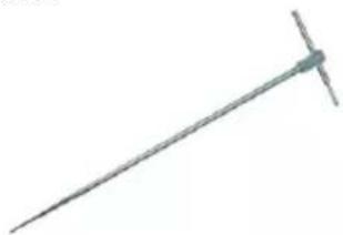
WASONG80V2
natural_image
Simple line drawing of a metal rod or tool with a flat end and a small protrusion (no text or symbols)• Auxiliary electrode, 80 cm
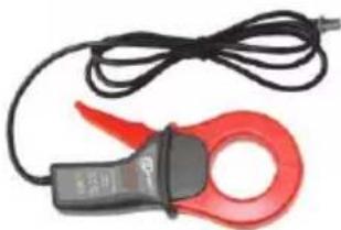
WACEGC3OKR
natural_image
Close-up of a red and black clamp meter with wire, no visible text or symbols- Reception clamp C-3
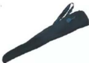
WAFUTL3
natural_image
Silhouette of a dark, elongated object resembling a tool or device (no text or symbols visible)- Case L-3 (for auxiliary electrodes 80 cm)
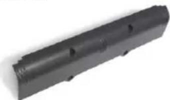
WAPOJ1
natural_image
Black cylindrical mechanical part with multiple holes, isolated on white background (no text or symbols)- Batteries compartment
WACEGN1BB
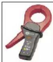
• Transmission clamp N-1
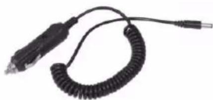
WAPRZLAD12SAM
natural_image
Coiled black cable with connectors and a connector terminal (no text or symbols visible)- Cable to charge the accumulators from the car lighter socket
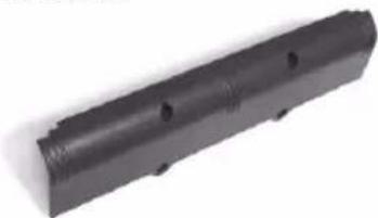
WAAKU07
natural_image
Black cylindrical mechanical part with three holes, shown against a white background (no text or symbols)• Rechargeable battery NiMH 4.8 V 4.2 Ah
• Calibration certificate with accreditation
12 Positions of the meter's cover
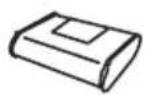
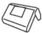
The movable cover enables using the meter in various positions.
1 2 3

natural_image
Line drawing of a person holding an open book (no text or symbols)1 - Cover as the bottom of the meter,
2 – Cover used as a support,
3 – Cover in the position that enables convenient use of the meter suspended on the neck by means of hanging straps.
13 Manufacturer
The manufacturer of the device, which also provides guarantee and post-guarantee service is the following company:
SONEL S.A.
Wokulskiego 11
58-100 Šwidnica
Poland
tel. +48 74 858 38 60
fax +48 74 858 38 09
E-mail: export@sonel.pl
Web page: www.sonel.pl
Attention: Service repairs must be realised solely by the manufacturer.
14 Laboratory services
SONEL Testing and Calibration Laboratory has been accredited by the Polish Center for Accreditation (PCA) - certificate no. AP 173.
Laboratory offers calibration for the following instruments that are used for measuring electrical and non-electrical parameters.
• METERS FOR MEASUREMENTS OF ELECTRICAL PARAMETERS
○ voltage meters,
○ current meters (including clamp meters),
○ resistance meters,
○ insulation resistance meters,
o earth resistance and resistivity meters,
○ RCD meters,
○ short-circuit loop impedance meters,
○ power quality analyzers,
○ portable appliance testers (PAT),
○ power meters,
○ multimeters,
- multifunction meters covering the functions of the above-mentioned instruments,
• ELECTRICAL STANDARDS
○ calibrators,
○ resistance standards,
• METERS FOR MEASUREMENTS OF NON-ELECTRICAL PARAMETERS
○ pyrometers,
○ thermal imagers,
○ luxmeters.
The Calibration Certificate is a document that presents a relation between the calibration standard of known accuracy and meter indications with associated measurement uncertainties. The calibration standards are normally traceable to the national standard held by the National Metrological Institute.
According to ILAC-G24 „Guidelines for determination of calibration intervals of measuring instruments", SONEL S.A. recommends periodical metrological inspection of the instruments it manufactures no less frequently than once every 12 months.
For new instruments provided with the Calibration Certificate or Validation Certificate at the factory, re-calibration should be performed within 12 months from the date of purchase, however, no later than 24 months from the date of purchase.
ATTENTION!
The person performing the measurements should be absolutely sure about the efficiency of the device being used. Measurements made with an inefficient meter can contribute to an incorrect assessment of the effectiveness of health protection and even human life.
NOTES
NOTES
NOTES
SONEL S.A.
Wokulskiego 11
58-100 Świdnica
Poland

+48 74 858 38 60
+48 74 858 38 00
fax +48 74 858 38 09
e-mail: export@sonel.pl
www.sonel.pl
- USER MANUAL
- EARTH RESISTANCE METER MRU-120
- TABLE OF CONTENTS
- Safety 5
- Menu....6
- Measurements....12
- Memory 29
- Data transmission....32
- Power supply....32
- Cleaning and maintenance ....37
- Storage....37
- Dismantling and disposal 37
- Technical data.... 38
- Accessories 42
- Positions of the meter's cover 44
- Manufacturer....44
- Laboratory services 45
- Safety
- Note:
- Menu
- Measurement settings
- Mains frequency
- Calibration of the measurement clamp C-3
- Notes:
- Earth resistivity settings
- Meter settings
- LCD contrast
- AUTO-OFF settings
- Display settings
- Date and time
- Battery discharging
- Program update
- Language choice
- Information on the manufacturer
- Measurements
- Measurement of resistance of earth connection and equipotential bonding (2P)
- Additional information displayed by the meter
- Calibration of the test leads
- Auto-zeroing on
- Auto-zeroing off
- Earth resistance measurement with 3-pole method (R E3P)
- Earth resistance measurement with 4-wire method (R E4P)
- Earth resistance measurement with 3-pole method with additional clamp ( R_E3P+C )
- Earth resistance measurement with two-clamp method (2C)
- Earth resistivity measurement ( )
- Memory
- Saving of the measurement results in the memory
- Memory erasing
- Memory browsing
- Data transmission
- Remarks:
- Computer connection accessories
- Connection of the meter to a computer
- Power supply
- Monitoring of the power supply voltage
- Replacement of accumulators
- WARNING:
- NOTE!
- Fuse replacement
- Charging of accumulators
- Discharging of accumulators
- General principles regarding using Ni-MH accumulators
- Cleaning and maintenance
- Storage
- Dismantling and disposal
- Technical data
- Basic data
- Measurement of resistance of protective conductors and equipotential bonding (2P)
- Measurement of earth resistance - 3-pole method (RE3P), 4-wire method (RE4P)
- Measurement of earth resistance - 3-pole method with additional clamp (R _E 3P+C)
- Earth resistivity measurement (ρ)
- Other technical data
- NOTE
- \* Information about the use of meter at altitude from 2000 m to 5000 m
- Additional data
- Influence of the serial interference voltage U_N upon earth resistance measurements for functions R_E3P , R_E4P , R_E3P+C
- Influence of the serial interference voltage U_N upon earth resistance measurements for function
- Influence of the auxiliary electrodes upon earth resistance measurements for function R_E3P , R_E4P , R_E3P+C
- Influence of the auxiliary electrodes upon earth resistance measurements for function
- Influence of the interference current I_1 upon the result of the earth resistance measurement for method R_E3P+C
- Influence of interference current on the result of the earth resistance measurement for two-clamp method (2C)
- Influence of the relation of the resistance measured with clamp for the multiple earthing branch to the resultant resistance ( R_E3P+C )
- Additional uncertainties in accordance with IEC 61557-4 (2P)
- Additional uncertainties in accordance with IEC 61557-5 (R _E3P , RE4P, RE3P+C)
- Accessories
- Standard accessories
- Optional accessories
- Positions of the meter's cover
- Manufacturer
- SONEL S.A.
- Laboratory services
- • METERS FOR MEASUREMENTS OF ELECTRICAL PARAMETERS
- • ELECTRICAL STANDARDS
- • METERS FOR MEASUREMENTS OF NON-ELECTRICAL PARAMETERS
- ATTENTION!
Brand : Sonel
Model : MRU-120
Category : Mètre