PVM-1020 - Mètre Sonel - Free user manual and instructions
Find the device manual for free PVM-1020 Sonel in PDF.


| Product Type | Photovoltaic Multifunction Meter |
| Model | PVM-1020 |
| Dimensions (H x W x D) | 228 x 102 x 61 mm |
| Weight | Approx. 1.0 kg |
| Power Supply | 4x AA alkaline LR6 or NiMH rechargeable batteries |
| Measurement Functions | Insulation resistance (PV and AC), open circuit DC voltage (Uoc), short circuit DC current (Isc), automatic DC measurements (Uoc, Isc, RisoPV), operating current and power (DC/AC), continuity (Rcont), low resistance (Rx), diode test (forward 200 mA, reverse 1000 V) |
| DC Voltage Measurement Range | 0.0 to 1000.0 V, accuracy ±(0.5% + 2 digits) |
| AC Voltage Measurement Range | 0.0 to 600.0 V (True RMS), accuracy ±(2% + 6 digits), frequency 45-65 Hz |
| Short Circuit Current (Isc) Range | 0.00 to 20.00 A, accuracy ±(1% + 2 digits) |
| Insulation Resistance Test Voltages | 250 V, 500 V, 1000 V |
| Insulation Resistance Ranges | PV: up to 1.000 GΩ (250/500/1000 V); AC: up to 9.999 GΩ (1000 V) |
| Operating Current and Power | Current: 0.0-40.0 A (accuracy ±5%+2) or 1.0-400.0 A (±5%+8); Power: 0.0-100.0 kW (±6%+5) |
| Continuity (Rcont) Range | 0.00 to 1999 Ω, test current 200 mA |
| Low Resistance (Rx) Range | 0.0 to 1999 Ω, test current 5-15 mA |
| Safety Category | CAT II 1000 V DC, CAT III 600 V, CAT IV 300 V |
| Ingress Protection | IP65 |
| Display | Graphical LCD with backlight (2 levels) |
| Memory | 4059 data records (99 objects x 40 cells + 1 collective per object) |
| Communication | Bluetooth (up to 10 m) for PC data transfer; LoRa (up to 300 m) with IRM-1 irradiance meter |
| Operating Temperature | -10°C to +40°C |
| Storage Temperature | -20°C to +60°C |
| Humidity | 20% to 80% |
| Auto-Off | 5, 10, 15 min or none (selectable) |
| Standards Compliance | IEC 61557-1/2/4/10, IEC 61010-1, IEC 61010-2-030/034, IEC 61326-1, IEC 62446-1 |
| Accessories Included | Test leads, current clamps (C-PV), IRM-1 irradiance meter (optional), Bluetooth module, software Sonel Reader |
Frequently Asked Questions - PVM-1020 Sonel
User questions about PVM-1020 Sonel
0 question about this device. Answer the ones you know or ask your own.
Ask a new question about this device
Download the instructions for your Mètre in PDF format for free! Find your manual PVM-1020 - Sonel and take your electronic device back in hand. On this page are published all the documents necessary for the use of your device. PVM-1020 by Sonel.
USER MANUAL PVM-1020 Sonel
natural_image
Line drawing of a handheld electronic device with control panel and buttons (no text or symbols)USER MANUAL
PHOTOVOLTAIC METER
PVM-1020
PVM-1020

USER MANUAL
PHOTOVOLTAIC METER
PVM-1020

SONEL S.A.
Wokulskiego 11
58-100 Świdnica
Poland
Version 1.11 13.11.2023
PVM-1020 is a modern, state-of-the-art measuring instrument, easy to operate and safe. Read this manual to avoid mistakes during the measurements and prevent operational problems.
CONTENTS
1 General information....5
1.1 Safety symbols....5
1.2 Safety....6
1.3 General characteristics 7
1.4 Compliance with standards 8
2 Quick start 9
2.1 Turning the meter on and off, display backlight 9
2.2 Selection of general measurement parameters 9
2.3 Remembering the last measurement result 9
2.4 Connectivity between IRM-1 and PVM-1020 11
2.4.1 Pairing the meters....11
2.4.2 Unpairing....12
2.4.3 Automatic completion of results with environmental parameters after regaining connection with the IRM-1....13
3 Measurements....14
3.1 Insulation resistance 14
3.1.1 Measurement of insulation resistance (PV) 14
3.1.2 Measurement of insulation resistance (AC)....17
3.1.3 Additional Information....19
3.2 DC voltage of open circuit U_OC 20
3.3 DC short circuit current I_SC ..... 21
3.4 Automatic measurements (DC) 23
3.5 Measurement of operating current and power 27
3.6 Resetting C-PV clamps 29
3.7 Low-voltage measurement of resistance 30
3.7.1 Compensation of test leads resistance - autozeroing 30
3.7.2 Low-current measurement of resistance 31
3.7.3 Measurement of continuity of protective conductors and equipotential bondings with ±200 mA current....33
3.8 Diode test with 200 mA current.... 35
3.9 Test of blocking diode with 1000 V voltage....37
4 Memory of measurement results....39
4.1 Recording measurement result data in the memory 39
4.2 Changing the cell and bank number 41
4.3 Viewing memory data.... 41
4.4 Deleting memory data.... 43
4.4.1 Deleting the selected object and its cells 43
4.4.2 Deleting the entire memory....44
5 Communication....45
5.1 Set of accessories to connect the meter to a PC 45
5.2 Data transmission using Bluetooth module.... 45
6 Troubleshooting....46
7 Power supply....46
7.1 Monitoring the power supply voltage.... 46
7.2 Replacing the (rechargeable) batteries 47
7.3 General rules of using the Nickel Metal Hydride (Ni-MH) batteries.... 47
8 Cleaning and maintenance 48
9 Storage....48
10 Dismantling and disposal 48
11 Technical data....49
11.1 Basic information 49
11.1.1 DC voltage measurement 49
11.1.2 AC True RMS voltage measurement 49
11.1.3 Frequency measurement 49
11.1.4 Measurement of I_SC short-circuit current .....49
11.1.5 Measurement of insulation resistance of the module/PV system 49
11.1.6 Measurement of insulation resistance....50
11.1.7 Measurement of operating current and power....51
11.1.8 Low-voltage measurement of continuity of circuit and resistance....51
11.1.9 Converting measurement results to STC conditions 51
11.2 Other technical specifications .... 52
11.2.1 Maximum operating time on one set of batteries....53
11.2.2 Maximum operating time on a single battery charge 53
12 Manufacturer ....54
1 General information
1.1 Safety symbols
The following international symbols are used in the device and/or in this manual:
 | Warning;See explanation in the manual |  | Ground |  | AC current/voltage |
 | DC current/voltage |  | Dual insulation (Protection class) |  | Declaration of Conformity with EU directives (Conformité Européenne) |
 | Do not dispose of with other house-hold waste |  | Recycling information |  | Confirmed compliance with Australian Standards |
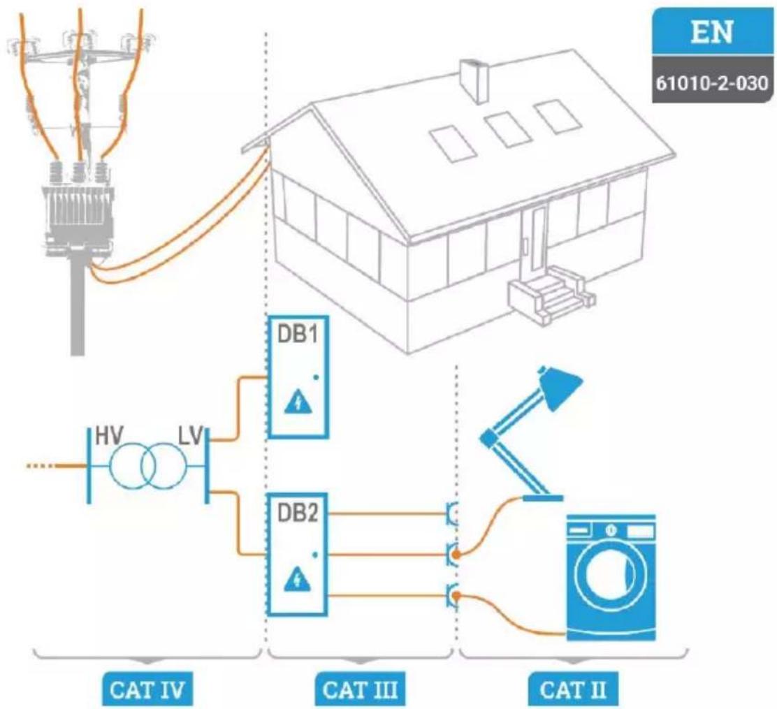
Measurement categories according to IEC 61010-2-030:
- CAT II – concerns measurements performed in circuits directly connected to low voltage installations,
- CAT III – concerns measurements performed in buildings installations,
- CAT IV – concerns measurements performed at the source of low voltage installation.
To avoid electric shock or fire, you must observe the following guidelines:
- Before you proceed to operate the device, acquaint yourself thoroughly with this manual and observe the safety regulations and specifications defined by the producer.
- Any application that differs from those specified in this manual may result in damage to the device and constitute a source of danger for the user.
- The device must be operated solely by appropriately qualified personnel with relevant certificates to realise measurements of electric installation. Operating the analyzer by unauthorised personnel may result in damage to the device and constitute a source of danger for the user.
- Using this manual does not exclude the need to comply with occupational health and safety regulations and with other relevant fire regulations required during the performance of a particular type of work. Before starting the work with the device in special environments, e.g. potentially fire-risk/explosive environment, it is necessary to consult it with the person responsible for health and safety.
- Before starting the work, check the device, wires, adapters, current probe and other accessories for any sign of mechanical damage. Pay special attention to the connectors
- It is unacceptable to operate:
it is damaged and completely or partially out of order,
its cords and cables have damaged insulation.
⇒ of the device and accessories mechanically damaged,
it was stored for an excessive period of time in disadvantageous conditions (e.g. excessive humidity) After moving the device from a cool to a warm place with a high level of relative humidity, do not start measurements until the device is warmed up to the ambient temperature (approximately 30 minutes).
- Do not operate a meter with an open or incorrectly closed battery (accumulator) compartment or power it from other sources than those specified in the present manual.
- Dangerous voltages occur inside the device. Before removing the battery cover, always disconnect all the test leads and turn off the device.
- symbol shown on the display indicates insufficient voltage of power supply and the need to charge the accumulator or replace batteries. Measurements performed with the meter supplied with insufficient voltage are burdened with additional errors that are impossible to be estimated by the user. Such measurements must not be used to confirm correctness of the tested photovoltaic installation or network.
- Battery spill and damage to the meter may occur if discharged batteries are left inside it.
• Before measurement, make sure that test leads are connected to appropriate measuring terminals. - Do not use the device in power supply systems with voltage higher than 600 V AC.
- Do not connect the inputs of the device to photovoltaic systems with voltage exceeding 1000 V DC and short-circuit current exceeding 20 A.
- The PE terminal should only be used to connect the ground of photovoltaic systems. Don't apply any voltage to it!
- Opening the socket plug of the current clamps results in the loss of its declared tightness, leading to a possible damage in adverse weather conditions. It may also expose the user to the risk of electric shock.
- Do not carry the meter holding it by the wire of current clamps.
• Repairs may be performed only by an authorised service point.

NOTE!
Only accessories intended for a given device should be used. Using other accessories may cause damage to measuring terminals, introduce additional measurement errors and create a risk for the user.

Due to continuous development of the meter's software, the actual appearance of tl display, in case of some of the functions, may slightly differ from the display presented in this operating manual.
- Do not touch the tested object during the R _ISO insulation resistance measurement or after the measurement before it is fully discharged. It may result in electric shock.
- It is forbidden to perform measurements: R x resistance, R cont continuity, and test lead compensation, on energized circuits. This may damage the meter.
1.3 General characteristics
PVM-1020 is a multifunctional measuring device designed to measure the parameters of photovoltaic systems and the parameters of the inverter connection points to the power grid. It allows you to perform the necessary measurements for a photovoltaic system according to category 1 specified in standard "IEC 62446-1 - Photovoltaic systems (PV). Testing, documentation and maintenance requirements. Part 1: Networked Systems. Documentation, acceptance and supervision".
Measured parameters:
- DC voltage of an open module / chain PV – U oc,
- AC voltage on the AC side (connection of the inverter to the power grid),
- DC short-circuit current of the PV module/chain – I _SC ,
- R _ISO PV insulation resistance of the PV system on the DC side by method 1 according to IEC 62446-1 standard (i.e. the measurement does not cause a module / string short-circuit), allowing the determination of the insulation resistance of the PV module / string at both poles: Riso+ and Riso-,
- R _ISO insulation resistance of the PV system on the AC side (connection of the inverter to the power grid),
- DC current and power of the PV module / string / system on the DC side,
• DC and power of the PV system on the AC side (connection of the inverter to the power grid), - circuit continuity (R _CONT ) of the earthing and equipotential bonding cables of the PV module / string,
- parameters of the blocking diode, used in PV systems.
The meter is equipped with banana sockets and a socket for current clamps. The sockets are used for functional measurements of the systems (when working with the inverter turned on). Measurements are made using the sockets marked as "+" and "-". The (PE) socket is used for measuring the insulation resistance of a photovoltaic system by the short-circuit method, which allows user to measure the system as a whole, in one measurement, regardless of its power.
The meter has two radio interfaces (not working simultaneously): Bluetooth and LoRa.
- The Bluetooth module is used for communication between the meter and a computer in order to download the results from the memory.
• The LoRa module is used for communication with IRM-1.

IRM-1 is a meter designed for measuring solar irradiance and the temperature of photovoltaic cells and their environment. The data it provides is necessary to convert the values measured by PVM-1020 to the STC conditions. The standardized values enable the user to determine whether the photovoltaic system is working with optimal efficiency and to check the PV modules for potential damage.
1.4 Compliance with standards
PVM-1020 meets the requirements of the following standards:
- IEC 61557-1 – Electrical safety in low voltage distribution systems up to 1 000 V AC and 1 500 V DC – Equipment for testing, measuring or monitoring of protective measures – Part 1: General requirements.
- IEC 61557-2 – Electrical safety in low voltage distribution systems up to 1 000 V AC and 1 500 V DC – Equipment for testing, measuring or monitoring of protective measures – Part 2: Insulation resistance.
- IEC 61557-4 – Electrical safety in low voltage distribution systems up to 1 000 V AC and 1 500 V DC – Equipment for testing, measuring or monitoring of protective measures – Part 4: Resistance of earth connection and equipotential bonding.
- IEC 61557-10 – Electrical safety in low voltage distribution systems up to 1 000 v a.c. and 1 500 v d.c. – Equipment for testing, measuring or monitoring of protective measures – Part 10: Combined measuring equipment for testing, measuring and monitoring of protective measures.
Safety standards:
- IEC 61010-1 – Safety requirements for electrical equipment for measurement, control, and laboratory use – Part 1: General requirements.
- IEC 61010-2-030 – Safety requirements for electrical equipment for measurement, control, and laboratory use – Part 2-030: Particular requirements for equipment having testing or measuring circuits.
- IEC 61010-2-034 – Safety requirements for electrical equipment for measurement, control, and laboratory use – Part 2-034: Particular requirements for measurement equipment for insulation resistance and test equipment for electric strength.
Standards for electromagnetic compatibility:
- IEC 61326-1 – Electrical equipment for measurement, control and laboratory use – EMC requirements – Part 1: General requirements.
Referenced standards
- IEC 62446-1 with Appendix A1 – Photovoltaic (PV) systems – Requirements for testing, documentation and maintenance – Part 1: Grid connected systems – Documentation, commissioning tests and inspection.
- IEC 60891 – Photovoltaic devices – Procedures for temperature and irradiance corrections to measured I-V characteristics.
2 Quick start
2.1 Turning the meter on and off, display backlight
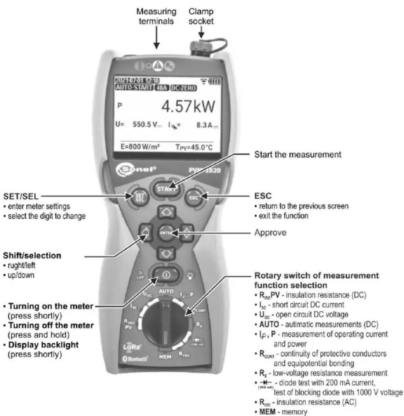
Briefly press 📄 button to turn on the meter. Press it for a longer time to turn it off (OFF is displayed).
Press briefly the button during meter operation to turn on/off the display and keypad display.
2.2 Selection of general measurement parameters
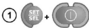
Keeping the SET/SEL button depressed, turn on the meter and wait for the parameter selection screen.
Use SET/SEL buttons to go to the next parameter.
Use ◀▶ buttons to go to the next parameter. The value or symbol to be changed is flashing.
Use ▲▼ buttons to change the parameter value. The value or symbol to be changed is flashing.
② Set the parameters according to the algorithm on the next page.
Press ENTER to approve the changes and go to the measuremer function or go to the measurement function without confirming the changes by pressing ESC.
2.3 Remembering the last measurement result
Result of the latest measurement is remembered by the meter until a next measurement is started or the measuring function is changed by means of the rotary switch or the meter is switched off. When entering the start screen of a given function by pressing the ESC button (or when it is displayed automatically 10 seconds after the measurement has been taken), the user may recall this result by pressing ENTER.
Meter settings
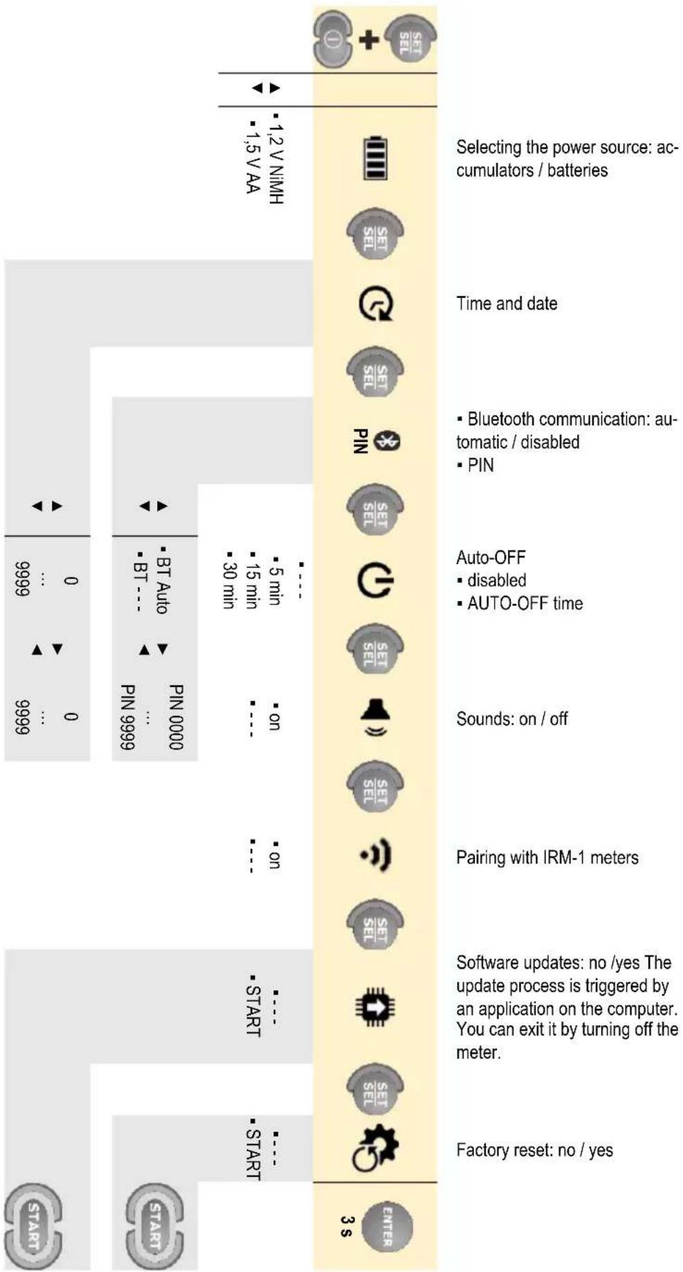
flowchart
graph TD
    A["Selecting the power source: accumulators / batteries"] --> B["Time and date"]
    B --> C["Bluetooth communication: automatic / disabled"]
    B --> D["PIN"]
    C --> E["Auto-OFF"]
    D --> F["Seals: on / off"]
    E --> G["Pairing with IRM-1 meters"]
    F --> H["Software updates: no /yes The update process is triggered by an application on the computer. You can exit it by turning off the meter."]
    G --> I["Factory reset: no / yes"]
    H --> J["START"]
    I --> K["START"]
    J --> L["START"]
    K --> M["3 S"]
2.4 Connectivity between IRM-1 and PVM-1020
If the IRM-1 meters have been paired with the PVM-1020, the device searches for them when turned on. When IRM-1 is found, a connection is established and the screen shows . The PVM-1020 remembers the last 3 paired IRM-1's.
2.4.1 Pairing the meters
If the pairing with the IRM-1 has not been made, it should be done as indicated below.
① Turn on the IRM-1 meter to be paired. Set it to pairing mode.
② In the PVM-1020 settings, enter the pairing screen with IRM-1.
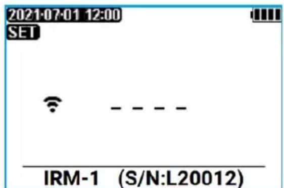
IRM-1 within the range of the meter
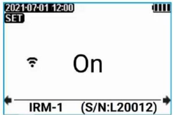
Many IRM-1's within range of the meter. There are other IRM-1 meters paired with PVM-1020 meter

2.4.2 Unpairing
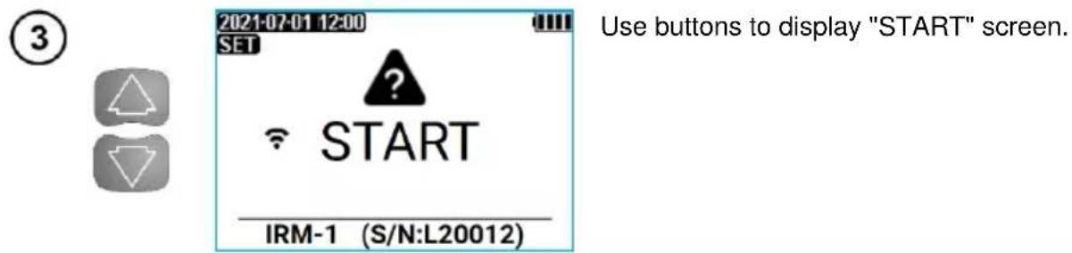
① In the PVM-1020 settings, enter the pairing screen with IRM-1.
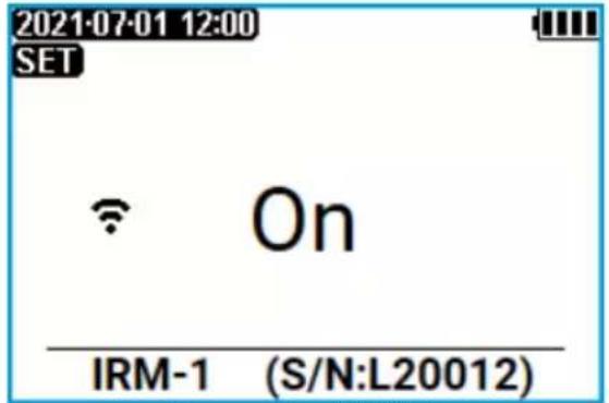
One paired IRM-1 within range of the meter
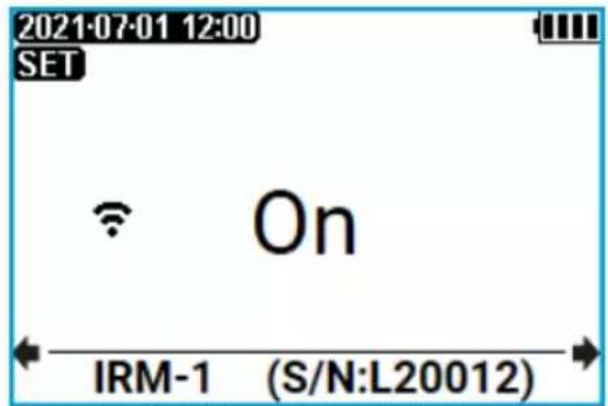
Multiple paired IRM-1's within range of the meter
②
.Use the serial number of IRM-1 to select the device to be unpaired
③
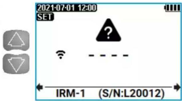
Use buttons to display "----" screen.
④
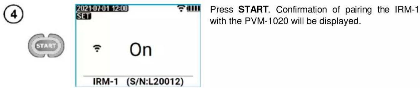
Press START.
⑤
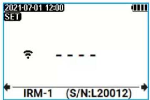
The pairing of IRM-1 with PVM-1020 has been deleted.
⑥

Press ENTER to go to the measurement screen and confirm the remaining meter settings. Press ESC to go to the measurement screen without confirming the remaining meter settings.
2.4.3 Automatic completion of results with environmental parameters after regaining connection with the IRM-1
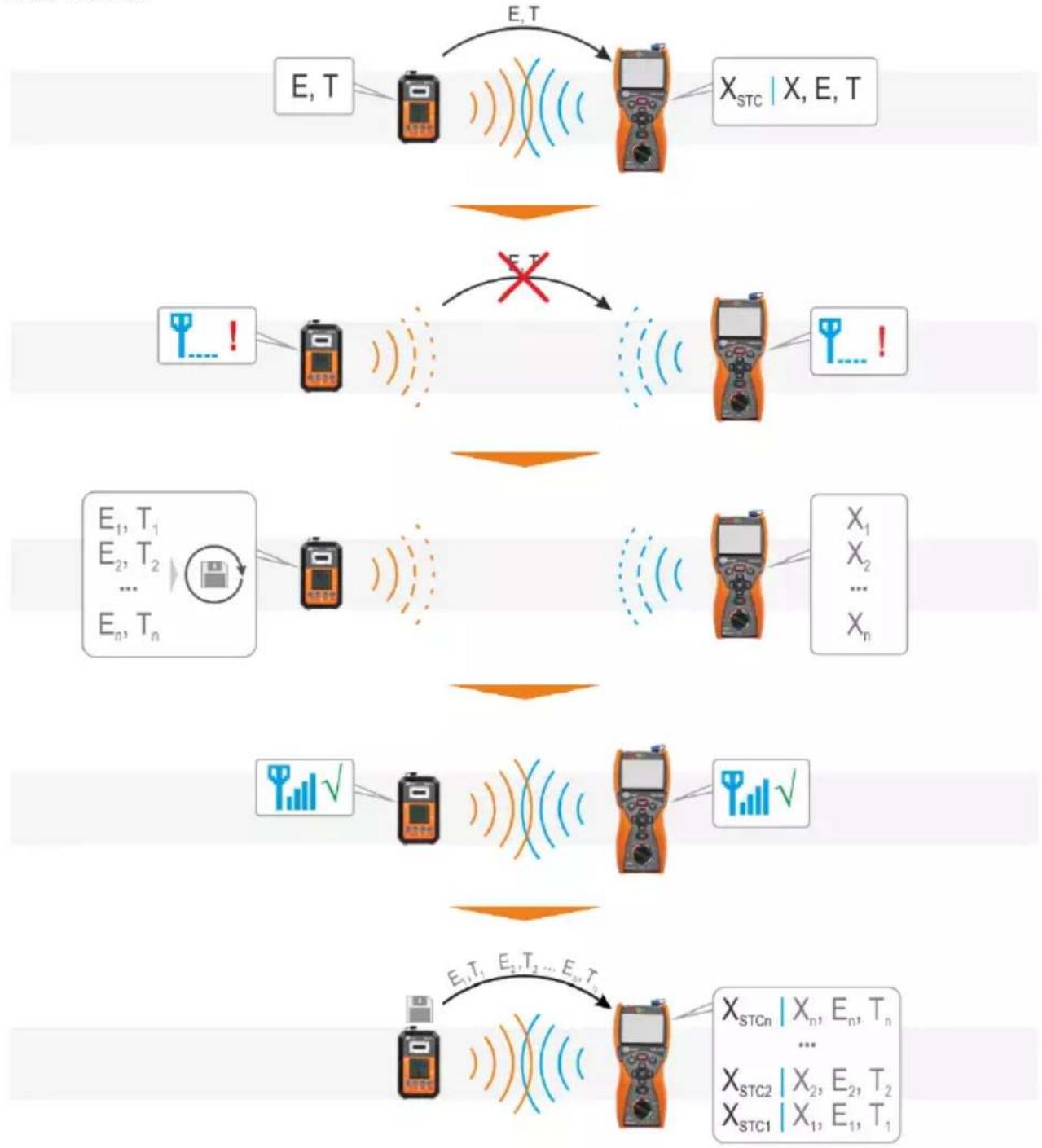
It may happen that in the course of measurements the PVM-1020 moves away from the IRM-1 so far, that communication between them is lost. If the measurements are continued, then after the connection is restored, the results will be automatically supplemented with environmental parameters, which in the meantime were recorded by the IRM-1 in its temporary memory, and converted into STC conditions.
flowchart
graph TD
    A["E, T"] -->|E, T| B["X_STC | X, E, T"]
    C["+"] --> D["+"]
    D -->|E, T| E["X_STC1 | X_1, E_1, T_1"]
    F["E_1, T_1\nE_2, T_2\n...\nE_n, T_n"] --> G["+"]
    G --> H["X_1\nX_2\n...\nX_n"]
    I["+"] --> J["+"]
    J --> K["X_STC2 | X_2, E_2, T_2\nX_STC1 | X_1, E_1, T_1"]
    L["+"] --> M["+"]
    M --> N["X_STCn | X_n, E_n, T_n\n...\nX_STC2 | X_2, E_2, T_2\nX_STC1 | X_1, E_1, T_1"]

- The number of supplemented environmental parameters is limited by the capacity of the IRM-1 temporary memory, and the data is transferred starting from the newest Therefore, it may happen that the oldest results are not completed.
- Supplementing a single result with environmental parameters may take – depending on the conditions – up to 60 seconds.
3 Measurements
WARNING
During a measurement, switching of the rotary switch is forbidden as it may damage the meter and pose a threat to the user.
3.1 Insulation resistance
3.1.1 Measurement of insulation resistance (PV)
WARNING
- Before testing the object, restrict access to it by unauthorized persons.
- Do not touch any metal parts of the photovoltaic system and the rear part of the modules during the measurement.
①
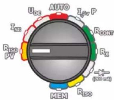
- Turn on the meter.
- Set the rotary switch of function selection at R_isoPV position.
②

Uiso

▲ · 250 V
▼ · 500 V
- 1000 V
- Press and hold SET/SEL.
- Set the measurement voltage according to the algorithm and according to the rules described in general parameters setting.
③
Connect test leads according to the drawings.
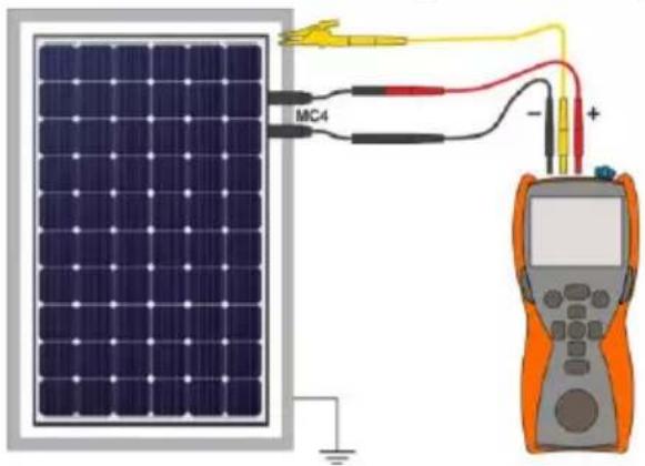
The PV system has an accessible, grounded structure (including frames of the module). Then one measurement is enough.
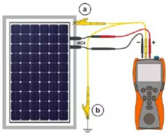
The PV system has no grounded structure. Then, two measurements are necessary:
a between system wires "+" , "-" and the system frame,
b between system wires "+" , "-" and the grounding.
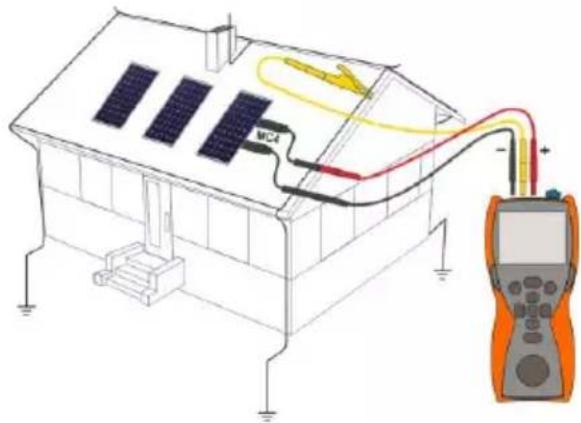
The PV system has no conductive parts available (e.g. solar roof tiles). Then, the measurement should be made between system wires "+" or "-" and grounding of the building.
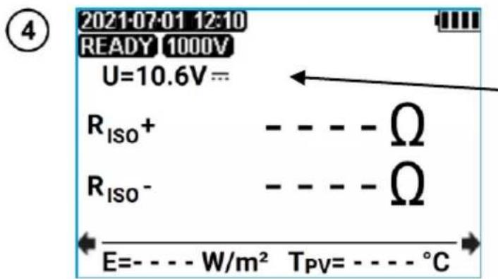
The meter is ready for measurement if it detects voltage U_DC ≥ 10 V on the object.
Voltmeter indicating voltage at the object

Press START. Measurement will begin.
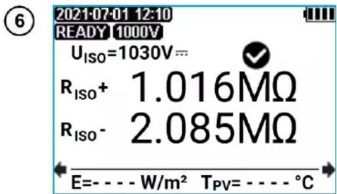
Read out the result.
U_ISO – test voltage
√ - compliance of the result with the requirements of IEC 62446 standard
E - solar irradiance of the tested object
T_PV — temperature of the tested object
⑦ To read additional results, press ◀▶.
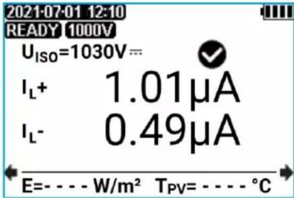
I_L+ – current flowing through the R+ resistance I_L- – current flowing through the R- resistance
WARNING
- During measurements of insulation resistance, dangerous voltage within the range of 250...1050 V is present at the ends of test leads of the meter.
- It is forbidden to disconnect test leads and to change the position of the function switch before completion of measurement. Failure to obey the above instruction will lead to high voltage electric shock and make it impossible to discharge the tested object.

- The meter emits a continuous audio signal until test voltage reaches 90% of the preset value (and also when 110% of the preset value is exceeded).
- After completion of measurement, the capacitance of the object tested is discharged by shorting "+" and "-" terminals with resistance of 140 kΩ.
- The result can be stored in the memory (see sec. 4.1). The last measurement result is stored until START button is pressed again or the position of rotary switch is changed.
Additional information displayed by the meter

The tested object is live. The measurement is blocked. Immediately disconnect the meter from the tested object (both leads)!

Activation of current limit. The symbol displayed is accompanied by a continuous beep.

The measurement was carried out, however without the guaranteed accuracy, because at the time of its performance there were disturbances causing the samples to differ from each other by more than 1%.

The tested object is being discharged.
3.1.2 Measurement of insulation resistance (AC)
WARNING
The tested object must not be live.
①
- Turn on the meter.
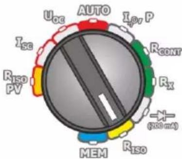
- Set the rotary switch of function selection at Riso position.
②

U_ISO

▲ · 250 V
▼ - 500 V
- 1000 V
- Press and hold SET/SEL.
- Set the measurement voltage according to the algorithm and according to the rules described in general parameters setting.
③
Connect test leads according to the drawing.
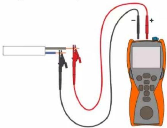
natural_image
Diagram of a multimeter connected to a U-shaped test tube with probe probes (no text or labels)④
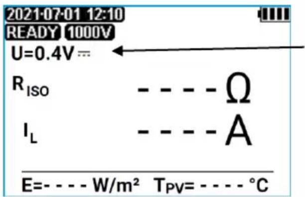
The meter is ready for measurement.
Voltmeter indicating voltage at the object
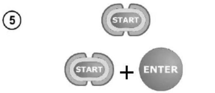
flowchart
graph TD
    A["START"] --> B["+"]
    C["START"] --> B
    B --> D["ENTER"]
Press and hold START button. The measurement will continue until the button is released.
To lock the measurement, while holding down press ENTER, while holding down START button. The measurement is interrupted by pressing START or ESC.
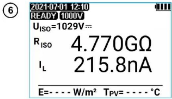
Read out the result.
U_ISO – test voltage
I_L – test current
E - solar irradiance of the tested object
T_PV – temperature of the tested object
WARNING
During measurements of insulation resistance, dangerous voltage in the range 250...1050 V occurs at the ends of the test leads of the meter. It is forbidden to disconnect the test leads and change the position of the function switch before the measurement is completed. Failure to obey the above instruction will lead to high voltage electric shock and make it impossible to discharge the tested object.

- During measurement, especially of high resistances, make sure that test leads do not touch each other and probes, because such a contact may cause the flow of surface currents resulting in additional error in measurement results.
- The meter emits a continuous audio signal until test voltage reaches 90% of the preset value (and also when 110% of the preset value is exceeded).
- During the measurement, the meter generates a beep every five seconds - it facilitates capturing time parameters.
- When the measurement cycle is upheld by pressing ENTER it is indicated by:
o a short break in the beep, when the test voltage has not reached 90% or exceeded 110% of set value,
o a short beep if the test voltage is between 90% and 110% of set value. - After completion of measurement, the capacitance of the object tested is discharged by shorting "+" and "-" terminals with resistance of 140 kΩ.
- The result can be stored in the memory (see sec. 4.1). The last measurement result is stored until START button is pressed again or the position of rotary switch is changed.
Additional information displayed by the meter


The tested object is live. The measurement is blocked. Immediately disconnect the meter from the tested object (both leads)!

Activation of current limit. The symbol displayed is accompanied by a continuous beep.
- The tested object is under the voltage within the range of 10 V...50 V. The measurement is possible, but without guaranteed accuracy.
- The tested object is under the voltage exceeding 50 V. The measurement is blocked.
Measuring range is exceeded.

The tested object is being discharged.
3.1.3 Additional Information
The meter measures the insulation resistance by applying to tested resistance R_x the U_ISO test voltage and measuring current I flowing through it, which is controlled from + terminal side. In calculating the value of insulation resistance, the meter applies the technical method of resistance measurement ( R_x=U/I ). The measuring voltage is selected from the values: 250 V, 500 V, 1000 V.
Inverter output current is limited at 2 mA level. The measurement result is correct, but on the test terminals the test voltage is lower than voltage selected before the measurement (as illustrated in figure below). Quite often current limitation may occur in the first phase of the measurement due to charging the capacity of the tested object.
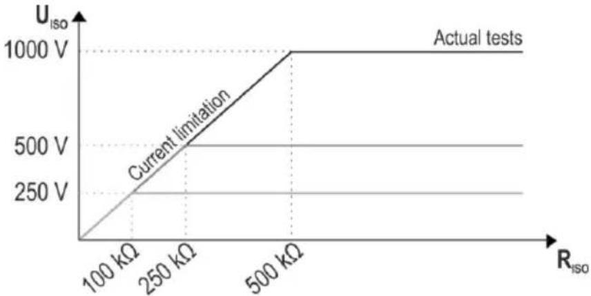
line
| R_iso (kΩ) | U_iso (V) | |------------|-----------| | 100 | 0 | | 250 | 500 | | 500 | 1000 |3.2 DC voltage of open circuit U oc
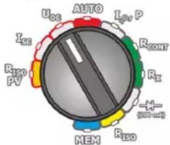
①
②
- Turn on the meter.
-
Set the rotary switch of function selection at U_oc .
-
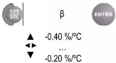
If the PVM-1020 is communicating with the IRM-1, press and hold SET/SEL.
- Set the temperature coefficient for the tested PV system according to the algorithm and rules described in setting general parameters.
Connect test leads according to the drawing.
③
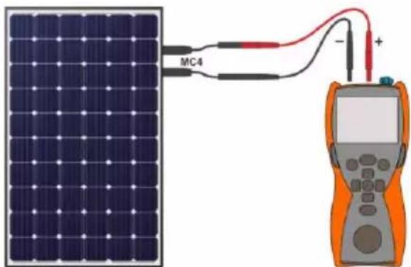
④
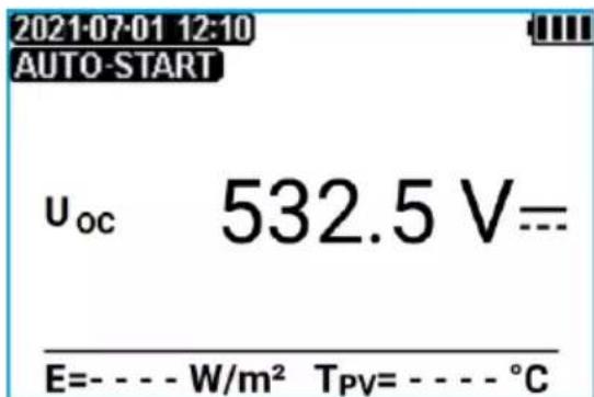
Read out the result.
Uoc – measured open circuit voltage
U_OC STC - measured U_OC voltage converted to STC conditions
E - solar irradiance of the tested object
T_PV – temperature of the tested object
Measurement result with inactive connection with IRM-1
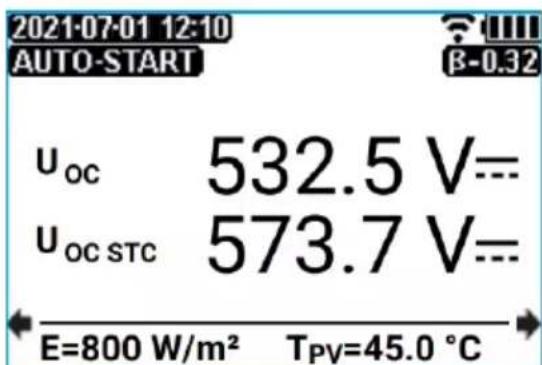

The result can be stored in the memory (see sec. 4.1). The last measurement result is stored until START button is pressed again or the position of rotary switch is changed.
Measurement result with inactive connection with IRM-1
3.3 DC short circuit current I sc
①
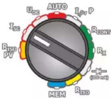
- Turn on the meter.
- Set the rotary switch of function selection at I_sc position.
②

0.020 %/°C
...
0.089 %/°C
- If the PVM-1020 is communicating with the IRM-1, press and hold SET/SEL.
- Set the temperature coefficient for the teste PV system according to the algorithm and rules described in setting general parameters.
③
If PVM-1020 is used for a measurement in a system with an optimizer, press briefly SET/SEL button. The DC/DC label will appear on the screen.
④
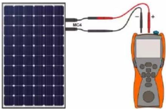
natural_image
Solar panel connected to a multimeter via wires, no text or symbols visibleConnect test leads according to the drawing.
⑤
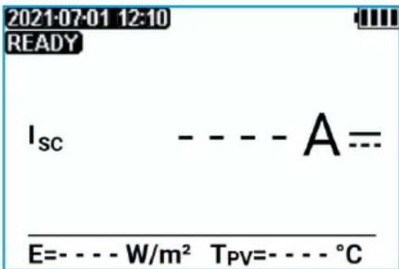
The meter is ready for measurement if it detects voltage U_DC ≥ 10 V on the object.
⑥
Press START.

NOTE!
During the measurement, the photovoltaic system is short-circuited for a short time. The test leads must not be disconnected during the measurement - there is a risk of electric arc ignition and damage to the meter.

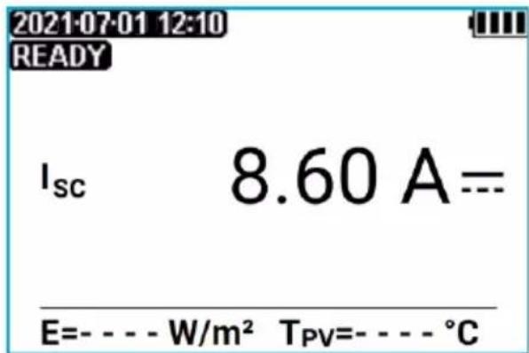
Measurement result with inactive connection with IRM-1
Read out the result.
I_SC – measured short circuit current I_SC STC – measured I_SC current converted to STC conditions E – solar irradiance of the tested object T_PV – temperature of the tested object
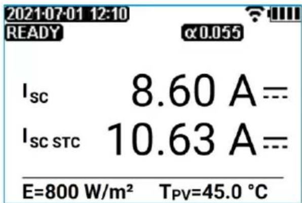
Measurement result with active connection with IRM-1

- The result can be stored in the memory (see sec. 4.1). The last measurement result is stored until START button is pressed again or the position of rotary switch is changed.
- In systems equipped with optimizers, short-circuit current measurements should be performed in the DC/DC mode. However, such measurements may be ineffective or affected by an unspecified error due to the design of the optimizers.
Additional information displayed by the meter
| LIMIT!! | Capacitance of the tested object is too high. Activation of current limit.The display of the symbol is accompanied by the message I_sc >20A . |
| NOISE! | Message displayed after measurement. This indicates significant discrepancies between partial measurements. The measurement result may be affected by a large, unspecified error (usually positive).No data from IRM-1 before and after short-circuit current measurement. |
| Test leads reversed or reverse polarity. The measurement is blocked. |
3.4 Automatic measurements (DC)
In automatic measurements, the user can measure R_ISOPV , U_OC , I_SC parameters with one connection (but not I_SC DC/DC for systems with an optimizer – an individual measurement must be performed here).
WARNING
- Before testing the object, restrict access to it by unauthorized persons.
- Do not touch any metal parts of the photovoltaic system and the back of the modules during the measurement.
①
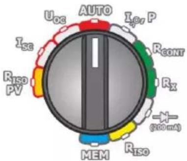
- Turn on the meter.
- Set the rotary switch of function selection at AUTO.
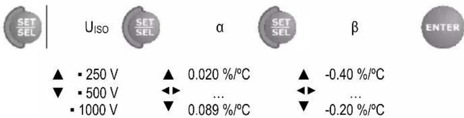
② Press and hold SET/SEL. Enter settings according to the following algorithm, and according to the rules described in general parameters setting. The and coefficients are available if the PVM-1020 is communicating with the IRM-1.
③
Connect test leads according to the drawings.
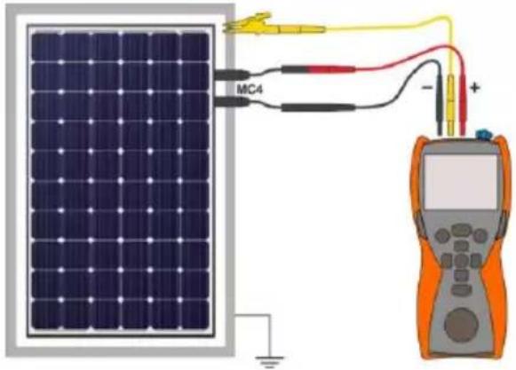
The PV system has an accessible, grounded structure (including frames of the module). Then one measurement is enough.
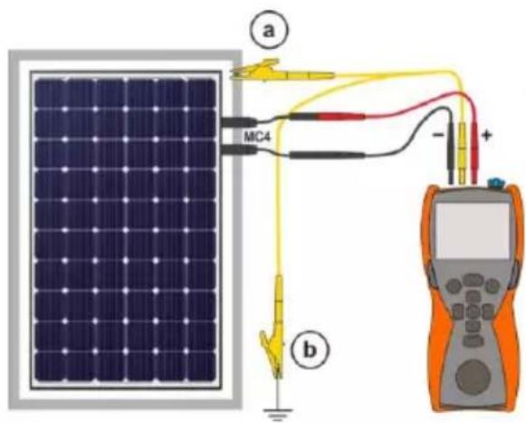
The PV system has no grounded structure. Then, two measurements are necessary:
a between system wires "+" , "-" and the system frame,
b between system wires "+" , "-" and the system frame,
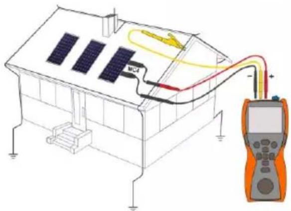
The PV system has no conductive parts available (e.g. solar roof tiles). Then, the measurement should be made between system wires "+" or "-" and grounding of the building.
④
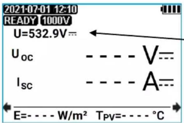
The meter is ready for measurement if it detects voltage U_OC ≥ 10 V .
Voltmeter indicating voltage at the object
⑤
Press START.

NOTE!
During the measurement, the photovoltaic system is short-circuited for a short time. The test leads must not be disconnected during the measurement - there is a risk of electric arc ignition and damage to the meter.

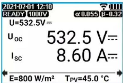
Read out the results.
The transition between screens is carried out using the ◀▶ buttons. If the PVM-1020 communicates with the IRM-1, there is an additional screen with the Uoc, Isc values converted to STC conditions.
U – voltmeter indicating voltage at the object U_OC – measured open circuit voltage Isc – measured short circuit current E - solar irradiance of the tested object T_PV – temperature of the tested object


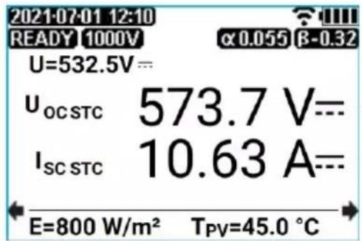
U_OC STC - measured U_OC voltage converted to STC conditions I_SC STC - measured I_SC current converted to STC conditions


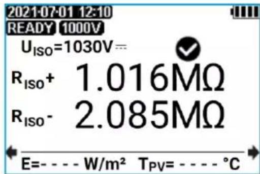
- compliance of the result with the requirements of IEC 62446 standard R_ISO+-R+ resistance R_ISO--R- resistance


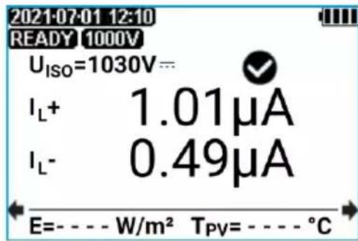
I_L+ – current flowing through the R+ resistance I_L- – current flowing through the R- resistance
WARNING
- During measurements of insulation resistance, dangerous voltage within the range of 1000...1050 V is present at the ends of test leads of the meter.
- It is forbidden to disconnect test leads and to change the position of the function switch before completion of measurement. Failure to obey the above instruction will lead to high voltage electric shock and make it impossible to discharge the tested object.

- The meter emits a continuous audio signal until test voltage reaches 90% of the preset value (and also when 110% of the preset value is exceeded).
- During the measurement, the meter generates a beep every five seconds - it facilitates capturing time parameters.
- After completion of measurement, the capacitance of the object tested is discharged by shorting "+" and "-" terminals with resistance of 140 kΩ.
- The result can be stored in the memory (see sec. 4.1). The last measurement result is stored until START button is pressed again or the position of rotary switch is changed.
Additional information displayed by the meter
| The tested object is live. The measurement is blocked. Immediately disconnect the meter from the tested object (both leads)! | |
| Riso (PV)Activation of current limit. The symbol displayed is accompanied by a continuous beep. | |
| IscCapacitance of the tested object is too high. Activation of current limit.The display of the symbol is accompanied by the message Isc >20A. | |
| Riso (PV)The measurement was carried out, however without the guaranteed accuracy, because at the time of its performance there were disturbances causing the samples to differ from each other by more than 1%. | |
| IscMessage displayed after measurement. This indicates significant discrepancies between partial measurements. The measurement result may be affected by a large, unspecified error (usually positive).No data from IRM-1 before and after short-circuit current measurement. | |
| The tested object is being discharged. | |
| Test leads reversed or reverse polarity. The measurement is blocked. |
3.5 Measurement of operating current and power
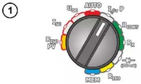
- Turn on the meter.
-
Set the rotary switch of function selection at I, P.
-
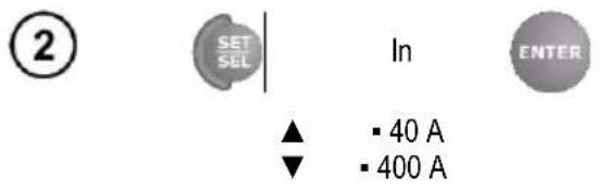
Set the measuring range on the C-PV clamp.
- Press and hold SET/SEL.
- Enter the measurement range of C-PV clamps according to the algorithm and according to the rules described in general parameters setting.
- Reset the clamps (sec. 3.6).
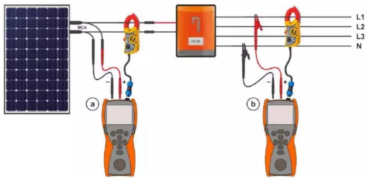
③ Connect the meter.
a DC side measurement,
b AC side measurement,
⑥
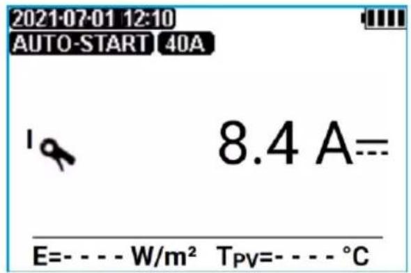
Read out the results.
The transition between the measurement functions is done with the SET/SEL button.
I - measured current
E - solar irradiance of the tested object
T_PV – temperature of the tested object

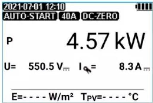
P - power generated (negative sign) or consumed (positive sign) by the tested object U - measured voltage I - measured current

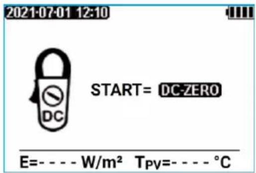
Screen of resetting (zeroing) clamps. See sec. 3.6.

- The result can save to the memory (see sec. 4.1). The last measurement result is stored until START button is pressed again or the position of rotary switch is changed.
- If a voltage and current clamp connection error is detected, i.e. if the measured voltage is DC and the current is AC (or vice versa), the power P will be displayed with a question mark indicating this error. That kind of result cannot be saved to the memory.
3.6 Resetting C-PV clamps
Before measuring the operating current of a PV system or power (sec. 3.5), reset the C-PV clamp. To do this, connect them to the meter, turn on the I, P function, and then use SET/SEL button to go to the clamps zeroing screen.
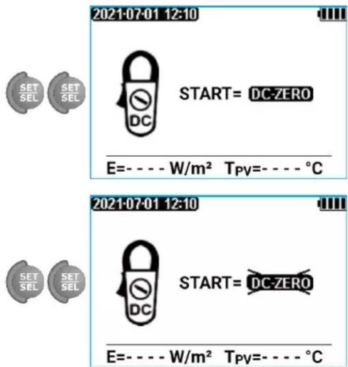
Pressing START resets the device, forcing the meter to indicate zero current. Only then you can connect the clamps to the tested object.
Entering the option again and pressing START will disable the reset.
Alternatively, set the DC ZERO knob on the housing of the clamps to make the current readings as close to zero as possible. However, it is recommended to zero the clamps in the meter according to the procedure described above.
3.7 Low-voltage measurement of resistance

NOTE!
It is forbidden to perform measurements: R × resistance, R CONT continuity, and test lead compensation, on energized circuits. This may damage the meter.
3.7.1 Compensation of test leads resistance - autozeroing
①
- Turn on the meter.
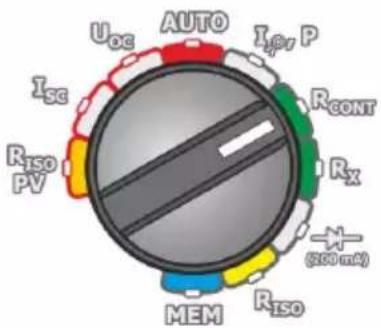
- Set the rotary switch of function selection at RCONT or Rx .
② Use button to enter the auto-zeroing mode.
③
natural_image
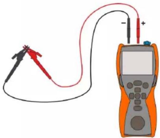
Illustration of a multimeter connected to a test strip with probe and power supply (no text or symbols)Short the test leads.
④
Activate the autozeroing by pressing the START button.
⑤
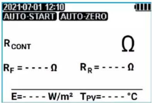
After completion of autozeroing, the meter automatically switches to the "ready form measurement" mode.

- Message AUTO-ZERO remains on the display after switching into one of the measurement fictions (resistance or continuity measurement) indicating that the measurement is made with compensated least leads resistance.
- The compensation is remembered even after the meter is switched off.
- To remove the compensation, perform the above-mentioned activities but with open test leads. After exiting to the measurement screen, A15C-35C will not be displayed.
Additional information displayed by the meter

The tested object is live. The measurement is blocked. Immediately disconnect the meter from the tested object (both leads)!
3.7.2 Low-current measurement of resistance
①
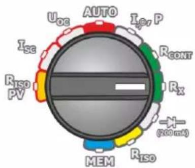
- Turn on the meter.
- Set the rotary switch of function selection at Rx.
②
2021-07-01 12:10 AUTO-START
[Non-Text]
The meter is ready for measurement.
R >1999 Ω
E=----W/m^2 T_PV=----^
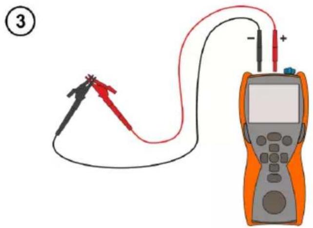
Connect test leads according to the drawing.
Read the measurement result.

For R < 30 , an acoustic signal is generated and the signalling diode lights up in green.
Additional information displayed by the meter
| The tested object is live. The measurement is blocked.Immediately disconnect the meter from the tested object (both leads)! | |
| AUTO-ZERO | The test leads compensation is activated for low-voltage resistance measurements. |
| AUTO-START | Automatic measurement activation. |
| >1999 Ω | Measuring range is exceeded. |
3.7.3 Measurement of continuity of protective conductors and equipotential bondings with ±200 mA current
①
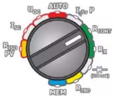
- Turn on the meter.
- Set the rotary switch of function selection at Rcont.
②
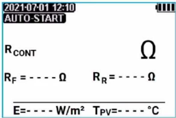
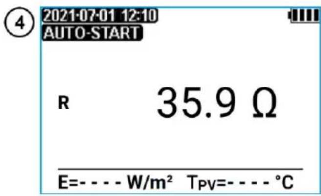
The meter is ready for measurement.
③
natural_image
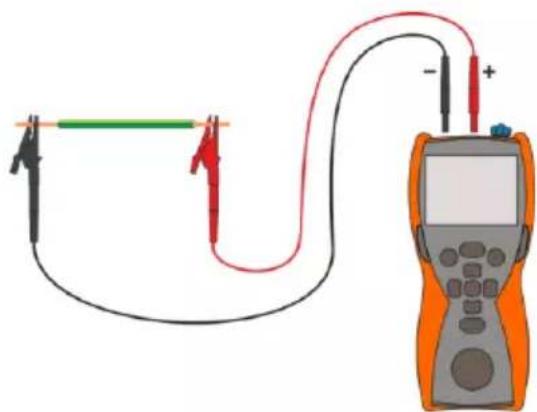
Simple electrical circuit diagram with a multimeter and two probes, no text or symbols presentConnect test leads according to the drawing. The measurement starts automatically for resistances lower than 21 Ω. The measurement may be also triggered with START button.
④
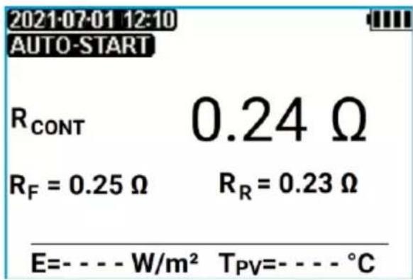
Read the measurement result.
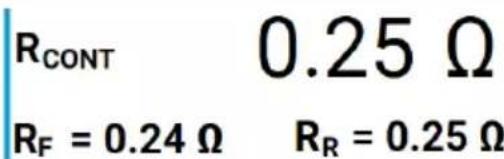
The result is the arithmetic mean of the values of two measurements at a current of 200 mA with opposite polarities R_F and R_R .
$$ R = \frac {R _ {F} + R _ {R}}{2} $$

Press START push-button in order to start next measurement without disconnecting test leads from the object or to measure the resistance, which is ≥21 .

The result obtained after pressing START can be stored in the memory (see sec. 4.1). The last measurement result is stored until START button is pressed again or the position of rotary switch is changed.
Additional information displayed by the meter
| The tested object is live. The measurement is blocked. Immediately disconnect the meter from the tested object (both leads)! | |
| AUTO-ZERO | The test leads compensation is on for low-voltage resistance measurements. |
| AUTO-START | Automatic measurement activation. |
| NOISE! | The message that appears after the measurement indicates significant discrepancies between the partial measurements (sec. 14)The measurement result may be affected by a large, unspecified error. Possible causes:interferences on the measured object too large,instability of the object or connections of the meter with this object (insecure galvanic connections). |
| >1999 Ω | Measuring range is exceeded. |
3.8 Diode test with 200 mA current
①
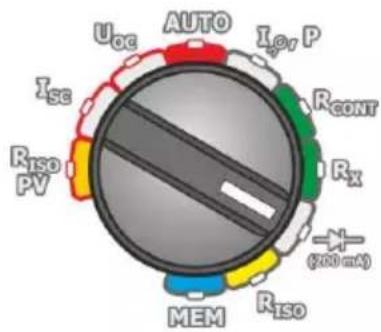
- Turn on the meter.
- Set the rotary switch of function selection at (200mA)
②
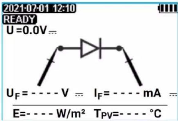
The screen for measuring voltage and current of the diode with positive polarity (in the forward direction) is shown.
③
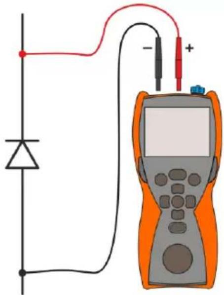
natural_image
Pure electrical circuit diagram showing a diode connected to a multimeter with a red and black wires, no text or symbols present.Connect test leads according to the drawing. The polarity when connecting the diode does not matter - the meter will automatically set it before taking the measurement.
④
Press START.

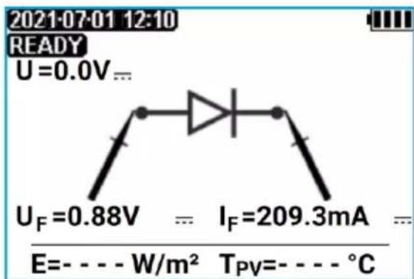
Read the measurement result.
If the measured diode is OK, the measured diode parameters will be displayed. Otherwise, symbols informing about damage (short-circuit or opening) of the measured element will be displayed.

- During the measurement of U_F / I_F parameters, the correctness of the diode connection to the meter is checked. As part of the measurements, with a reverse connection, information about this fact will appear (next to the probe symbols, information about the polarity of the probe connected to the appropriate tip of the measured diode will be displayed).
- The result can be stored in the memory (see sec. 4.1). The last measurement result is stored until START button is pressed again or the position of rotary switch is changed.
- The memory of this measurement is divided into two parts: diode test with 200 mA current (in the conducting direction U_F/I_F ) and blocking diode test with 1000 V current (in the blocking direction, U_R/I_R ). In order to have all diode parameters saved in the memory, it is necessary to:
⇒ perform a test with 200 mA current and save it to the memory cell,
⇒ perform a blocking diode test with 1000 V and save it to the same cell. If parameters are saved in the cell for the first time, no warning about data overwriting is be displayed.
3.9 Test of blocking diode with 1000 V voltage
①
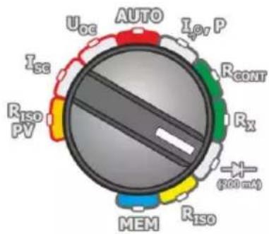
- Turn on the meter.
- Set the rotary switch of function selection at

②
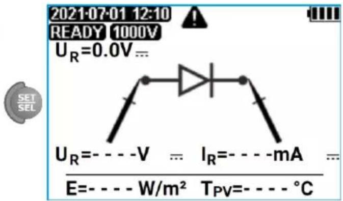
Press SET/SEL to activate the negative (reverse) voltage and current measurement screen. This test verifies that the blocking diode is correctly resisting 1000 volts in the reverse direction.
③
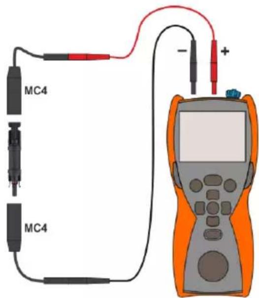
Connect test leads according to the drawing. The polarity when connecting the diode does not matter - the meter will automatically set it before taking the measurement.
④
Press START.
WARNING
During the measurement of the U _R /IR parameters, the meter generates dangerous measuring voltage of 1000 V.

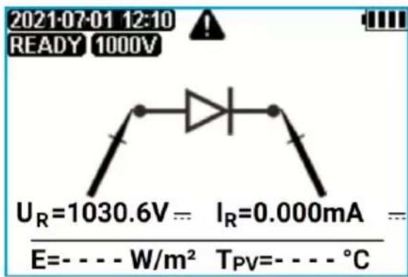
Read the measurement result.
If the measured diode is OK, the measured diode parameters will be displayed. Otherwise, symbols informing about damage (short-circuit or opening) of the measured element will be displayed.

- During the measurement of U_R / I_R parameters, the correctness of the diode connection to the meter is checked. As part of the measurements, with a reverse connection, information about this fact will appear (next to the probe symbols, information about the polarity of the probe connected to the appropriate tip of the measured diode will be displayed).
- The result can be stored in the memory (see sec. 4.1). The last measurement result is stored until START button is pressed again or the position of rotary switch is changed.
- The memory of this measurement is divided into two parts: diode test with 200 mA current (in the conducting direction U_F/I_F ) and blocking diode test with 1000 V current (in the blocking direction, U_R/I_R ). In order to have all diode parameters saved in the memory, it is necessary to:
⇒ perform a test with 200 mA current and save it to the memory cell,
perform a blocking diode test with 1000V and save it to the same cell. If parameters are saved in the cell for the first time, no warning about data overwriting is be displayed.
4 Memory of measurement results
The entire memory is divided into 99 memory objects with 40 memory cells each. Additionally, one collective data record may be entered into each object. This makes a total of 4059 data records. Due to dynamic memory allocation, each of the memory cell can contain different quantity of single measurement results, depending on the needs. Optimal use of the memory can be ensured in this way. Each measurement result can be stored in a memory cell marked with a selected number and in a selected memory object. Thanks to this, the user of the meter can, at his/her option, assign memory cell numbers to individual measurement points and the memory object numbers to individual facilities. The user may also perform measurements in any chosen sequence and repeat them without losing other data.
Memory of measurement results is not deleted when the meter is switched off. Thanks to this, the data can be later read or sent to a computer. The number of a current memory cell or memory object is not changed either.

- Results of measurements performed for all measuring functions can be stored in one memory cell.
- After each entry of the measurement result to the cell, its number is automatically incremented. Set the appropriate cell number to allow entering to a single cell of successive measurement results relating to a given measuring point (object).
- All measurements can be saved to the memory, except for the Rx resistance.
- It is recommended to delete the memory after reading the data or before performing a new series of measurements that may be stored into the same memory cells as the previous ones.
4.1 Recording measurement result data in the memory
Press ENTER after finishing the measurement.
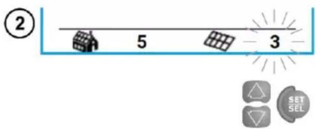
The meter is in the memory storing mode. Select an object and a cell according to sec 4.2 or leave the current one.
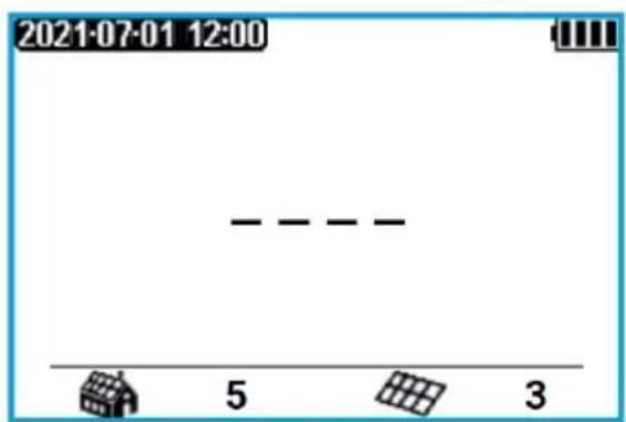
The cell is empty.
The cell contains the result of the same type which is to be entered.
The cell is occupied by the result of the displayed type.
The cell is occupied by the results of the displayed types.


Confirm the selection by pressing ENTER.

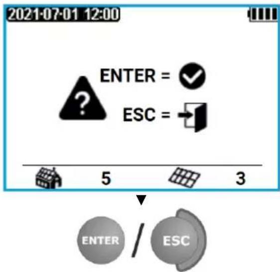
An attempt to overwrite a result causes displaying of warnings.
Press ENTER to overwrite the result or ESC to abort.

Complete set of results (main result and supplementary results) for a given measuring function, preset measurement settings, date and time of the measurement are stored in the memory. Additional data from the IRM-1 Irradiance Meter can also be saved.
4.2 Changing the cell and bank number
flowchart
graph TD
    A["ENTER"] --> B["5"]
    B --> C["3"]
    C --> D["SET SEL"]
    D --> E["5"]
    E --> F["3"]
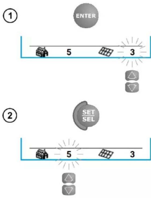
Press ENTER after completing of the measurement. The meter is in the memory storing mode.
The cell number is flashing.
You can change the cell number by pressing ▲▼.
Use the SET/SEL button to select the number of the cell or object active or to be deleted (flashing).
The object number is flashing.
You can change the bank number by pressing ▲▼.
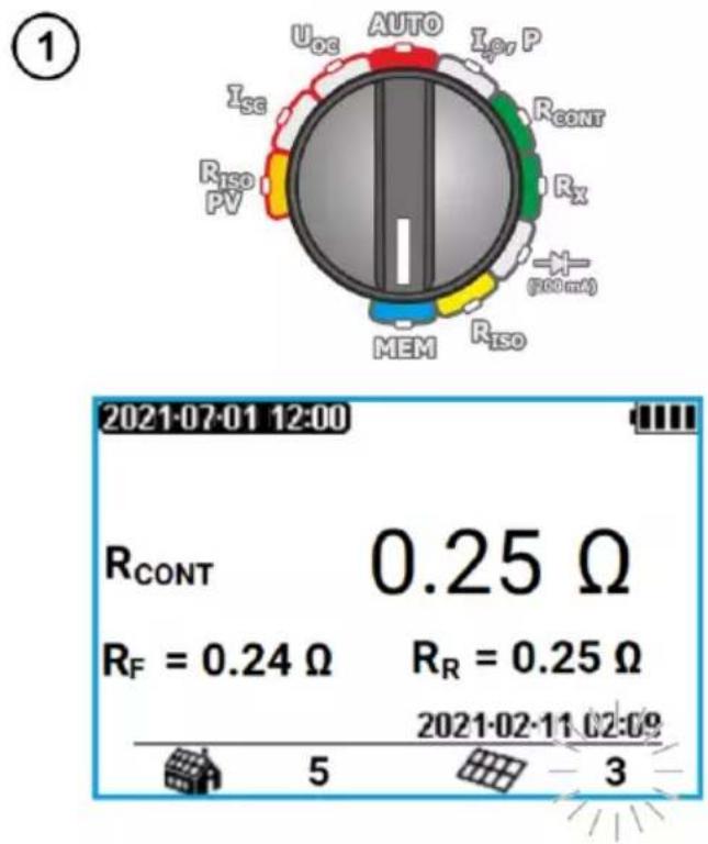
4.3 Viewing memory data
pie
| Component | Value | | :--- | :--- | | Uoc | 0.25 Ω | | AUTO | 0.25 Ω | | Isc, P | 0.25 Ω | | Isc | 0.24 Ω | | RCONT | 0.25 Ω | | Rx | 0.25 Ω | | (100 m²) | 0.25 Ω | | MEM | 0.25 Ω | | Riso | 0.25 Ω | | RF | 0.24 Ω | | 2021-02-11 02:09 | 0.25 Ω | | 5 | 0.25 Ω | | 3 | 0.25 Ω |- Turn on the meter.
- Set the rotary switch of function selection at MEM.
The content of the last saved cell appears.
The cell number is flashing.
To change the number of the bank/cell which content you want to see press SET/SEL and then ▲▼. If the bank or cell number is flashing - it may be changed.
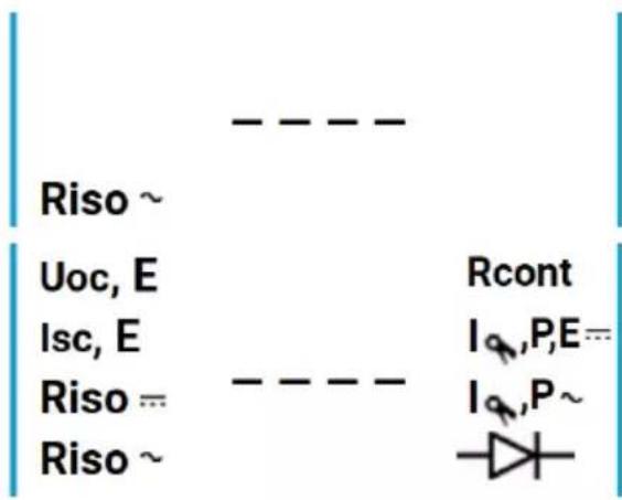
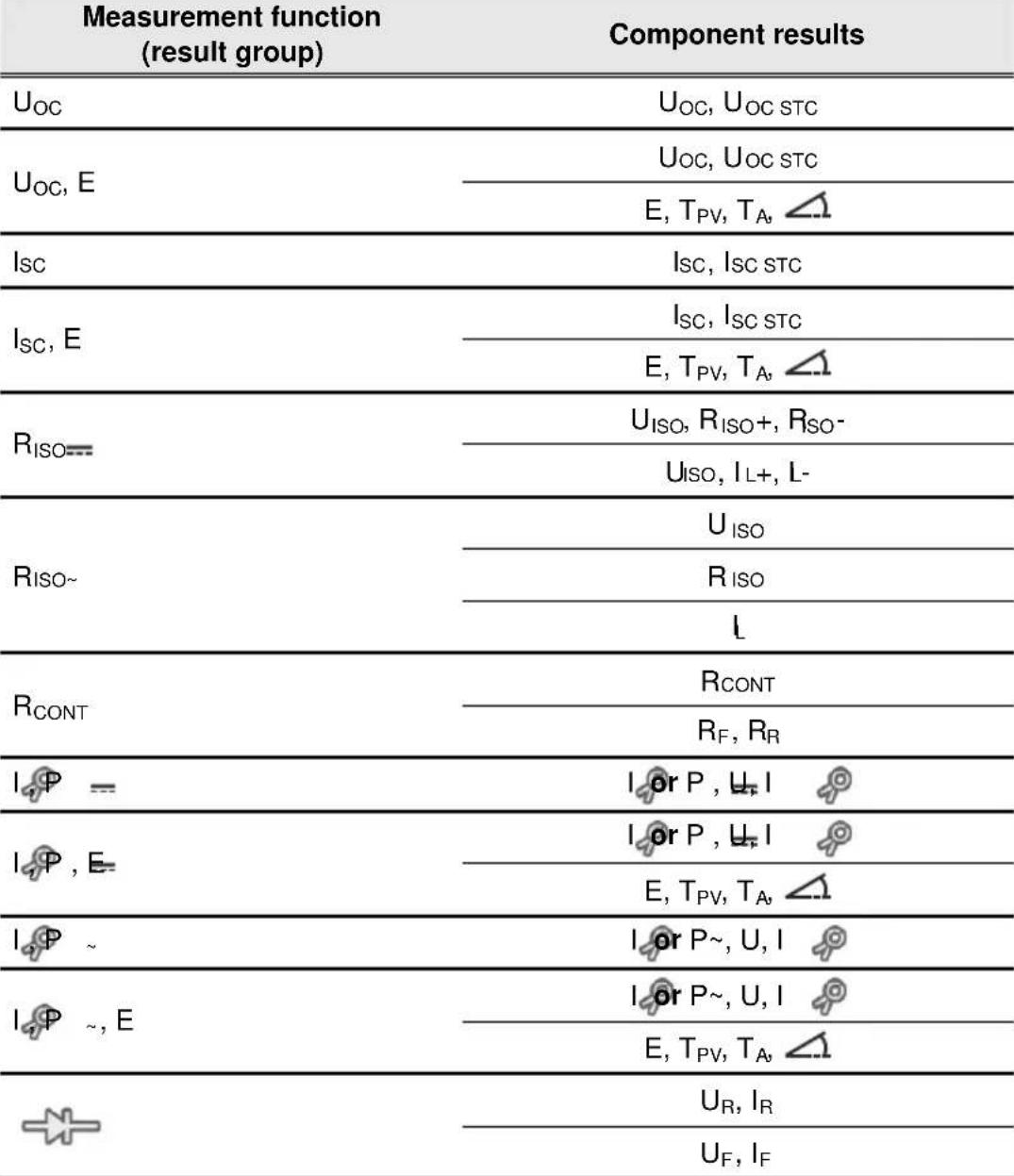
The following table specifies the sequence of data storing for individual measurement results.
 |
4.4 Deleting memory data
4.4.1 Deleting the selected object and its cells
①
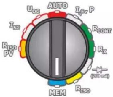
- Turn on the meter.
- Set the rotary switch of function selection at MEM.
②
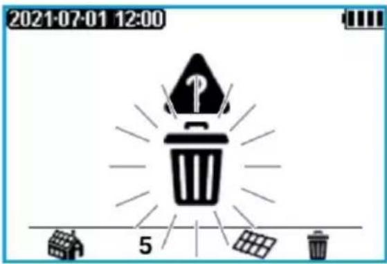
Set the number of the object to be deleted acc. sec. 4.2.
Set the cell number on a selected object 📄before
“1”). Symbols nuclear, indicating the readiness to delete.
③

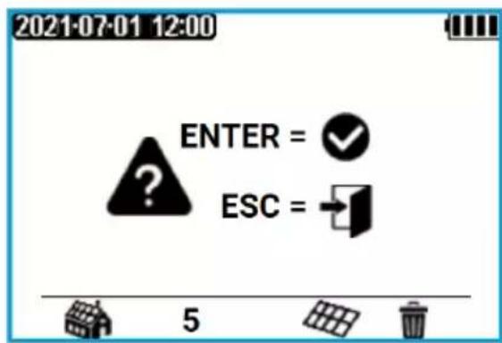
Press ENTER. A prompt for confirming deletion is shown.
④

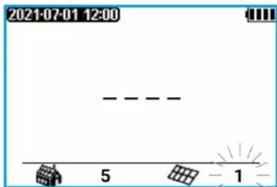
Press ENTER to start deleting or ESC to abort.
When deletion is complete, the meter generates three short beeps and sets the cell number to "1".
4.4.2 Deleting the entire memory
①
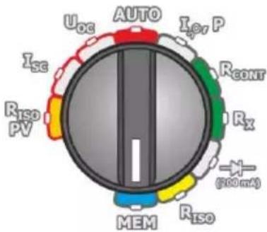
- Turn on the meter.
- Set the rotary switch of function selection at MEM.
②
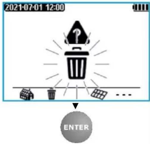
Set the object number to 📄 (before 1). Symbols
appear, indicating the readiness to delete.
Press ENTER.
③
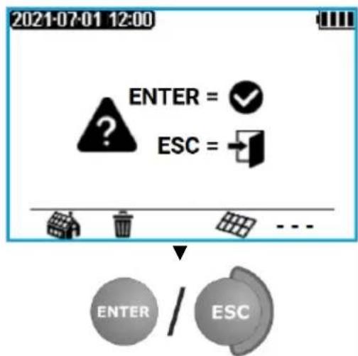
flowchart
graph TD
    A["ENTER"] --> B{?}
    B --> C["ESC"]
    C --> D["..."]
    D --> E["ENTER / ESC"]
A prompt for confirming deletion is shown.
Press ENTER to start deleting or ESC to abort.
④
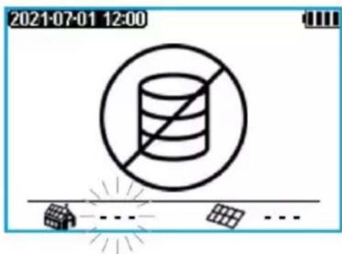
When deletion is complete, the meter generates three short beeps and sets the cell number to "1".
5 Communication
PVM-1020 is equipped with two communication channels: wireless Bluetooth and wireless LoRa®.
Wired communication via Bluetooth is used to transfer the results from the device's memory. Wireless communication in the LoRa® standard is used to receive measurement results from IRM-1. Any loss of communication does not result in data loss. The readings are then recorded in the temporary memory of IRM-1 and transmitted to PVM-102 meter after the communication is restored.
5.1 Set of accessories to connect the meter to a PC
In order to ensure the communication of the meter with a computer, Bluetooth module is required with an additional software. A program that may be used for this purpose is Sonel Reader. It allows users to read and display the measurement data stored in the meter memory. Software may be downloaded free from the manufacturer's website. Information on the availability of other programs cooperating with the meter may be obtained from the manufacturer or its authorized distributors.
The software may be used for many devices manufactured by SONEL S.A. which are equipped with the USB interface and/or wireless module.
Detailed information is available from the manufacturer and distributors.
5.2 Data transmission using Bluetooth module
① SET/SEL + ① Keeping the SET/SEL button depressed, turn on the meter and wait for the parameter selection screen (see sec. 2.2).
② SET/SEL Use the SET/SEL button to go to parameter
③ Use the ▲▼ buttons to set Auto.
4 ENTER Press and hold ENTER to confirm settings. From now on, after selecting the MEM position with the knob, symbol will be displayed on the screen.
⑤ Connect Bluetooth module to the USB socket of the PC, unless it is integrated into the PC.
⑥ During the process of pairing the meter with a PC, enter PIN code compatible with the PIN code of the meter defined in main settings.
⑦ Start Sonel Reader on the computer.

The standard PIN of the meter is 1234. Setting in the meter according to sec. 2.2.
6 Troubleshooting
Before sending the instrument for repairs, call our service. Perhaps the meter is not damaged, and the problem has been caused by some other reasons.
The meter can be repaired only at outlets authorized by the manufacturer.
Troubleshooting of typical problems during the use of the meter is described in the table below.
| Symptom | Cause | Action |
| The meter does not start after pressing button1During the voltage measurement the following symbol is displayed: | Discharged or incorrectly placed batteries rechargeable batteries. | Check if the batteries are placed correctly, replace and/or recharge the rechargeable batteries. If this does not help, sent the meter for servicing. |
| When connected to a voltage source, the meter shows a value of zero or close to zero. | The meter is damaged (blown fuses in the device). | Send the instrument to the service centre. |
| Measurement errors after moving the meter from cold environment to a warm and humid place. | No acclimatization. | Do not perform the measurements until the meter reaches the ambient temperature (about 30 minutes) and dries. |
| Error E222. | Too high voltage with reverse polarity is present at the terminals. | Disconnect the meter from the voltage, turn it off and on again. |
| Error E224. | Damage to the IGBT transistor. | Send the instrument to the service centre. |
Error E225.  | Damage to the IGBT transistor and the main relay. | Disconnect the meter from the tested object in a quick and decisive way to minimize the ignition of the electric arc between the disconnected elements. Send the instrument to the service centre. |
| Other error code. | Unspecified. | Turn the meter off and on again. If the error persists, send the instrument to the service centre. |
7 Power supply
7.1 Monitoring the power supply voltage
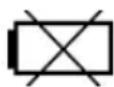
The batteries charging level is indicated by the symbol located in the screen:
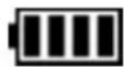
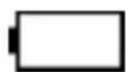

Batteries / rechargeable batteries charged.
Batteries / rechargeable batteries discharged.
Replace batteries or recharge rechargeable batteries. The meter switches off automatically.
7.2 Replacing the (rechargeable) batteries
The meter is powered by four AA alkaline LR6 batteries or rechargeable batteries of NiMH type. The (rechargeable) batteries are placed in the compartment at the bottom of the enclosure.
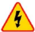
WARNING
Before replacing the (rechargeable) batteries, disconnect the test leads from the meter.
To replace the batteries/ rechargeable batteries:
- Disconnect the leads from the measuring circuit and turn off the meter,
- Remove the screws that secure the battery cover at the bottom of the compartment,
- Replace all batteries (rechargeable batteries). Observe the correct polarity when inserting new batteries/rechargeable batteries ("-" on the elastic part of the contact plate). Reverse polarity will not damage the meter or the batteries, but the meter will not work.
- Place and tighten the battery compartment cover.

NOTE!
- After replacing the batteries/rechargeable batteries, always set the power supply source. This setting influences the correct indication of the charging status (discharging characteristics of disposable and rechargeable batteries are different).
- Have the meter serviced in case of battery leakage inside the compartment.
Rechargeable batteries must be recharged in an external charger.
7.3 General rules of using the Nickel Metal Hydride (Ni-MH) batteries
- If you are not going to use the instrument for a longer time, remove the rechargeable batteries and store them separately.
- Store the rechargeable batteries in a dry, cool and well ventilated place and protect them from direct sunlight. The long storage temperature should be below 30°C. If the batteries are stored long at high temperatures, the chemical processes may reduce their life.
- The NiMH rechargeable batteries usually withstand 500-1000 charging cycles. Such batteries achieve full capacity after forming (2-3 discharging and charging cycles). The most important factor which influences the battery life is the discharge level. The deeper the discharge level, the shorter the battery life.
- The memory effect appears in the NiMH batteries in a limited scope. These batteries can be re-charged without more serious consequences. It is, however, recommended to discharge them completely every few cycles.
- During the storage of the Ni-MH rechargeable batteries, they are subject to self-discharge process at the rate of about 30% a month. Keeping the batteries at high temperatures may accelerate this process even two times. In order not to allow an excessive discharging of the batteries (after which the forming will be needed), recharge the batteries once in a while (even unused batteries).
-
Modern, fast chargers detect too low and too high temperature of the batteries and respond accordingly. If the temperature is too low, the charging process should not start as it might irrevocably damage a rechargeable battery. The battery temperature increase is a signal to stop the charging and is typical. In addition to faster temperature increase of a battery which will not be fully charged, charging at high ambient temperatures results, however, in a reduced life.
-
Remember that with fast charging, the batteries are charged to about 80% of their capacity; better results can be achieved by continuing the charging process: the charger then goes into the small current charging mode and after a few hours the batteries are fully charged.
- Do not charge and do not use the batteries at extreme temperatures as they reduce the life of batteries. Avoid using the battery-powered devices in very hot places. The rated operating temperature must be observed at all times.
8 Cleaning and maintenance

NOTE!
Use only the maintenance methods presented by the manufacturer in this manual.
Clean the meter casing with a wet cloth, using generally available detergents. Do not use any solvents and cleaning media which could scratch the casing (powder, paste, etc.).
The probes can be cleaned with water and then wiped dry. Before longer storage, it is recommended to lubricate the probes with any machine grease.
Clean the leads with water and detergents, then wipe dry.
The meter electronic system is maintenance free.
9 Storage
When storing the instrument, observe the following recommendations:
- disconnect all leads from the meter,
• thoroughly clean the meter and all accessories, - if you are not going to use the instrument for a longer time, remove the batteries,
• during a prolonged storage recharge the batteries from time to time to prevent total discharging.
10 Dismantling and disposal
Used electric and electronic equipment should be collected selectively, i.e. not placed with other types of waste.
Used electronic equipment shall be sent to the collection point according to the Used Electric and Electronic Equipment Act.
Before sending the instrument to the collection point, do not dismantle any parts by yourself.
Observe local regulations on disposal of packagings and used batteries.
11 Technical data
11.1 Basic information
⇒ The abbreviation "m.v." used in the specification of accuracy denotes a measured value
11.1.1 DC voltage measurement
| Display range | Resolution | Accuracy |
| 0.0...1000.0 V | 0.1 V | ±(0.5% m.v. + 2 digits) |
11.1.2 AC True RMS voltage measurement
| Display range | Resolution | Accuracy |
| 0.0...600.0 V | 0.1 V | ±(2% m.v. + 6 digits) |
• Frequency range: 45...65 Hz
11.1.3 Frequency measurement
Test range: 45.0...65.0 Hz
| Display range | Resolution | Accuracy |
| 40.0...300.0 Hz | 0.1 Hz | ±0.2 Hz |
• Voltage range: 10...600 V
11.1.4 Measurement of I_sc short-circuit current
| Display range | Resolution | Accuracy |
| 0.00...20.00 A | 0.01 A | ±(1% m.v. + 2 digits)* |
* For I_SC DC/DC the error is not specified
11.1.5 Measurement of insulation resistance of the module/ PV system
Measurement of Riso resistance
Test range according to IEC 61557-2 for U_ISO = 250 V / 500 V / 1000 V : 250 kΩ...1.000 GΩ
| Display range | Resolution | Accuracy |
| 0.0...999.9 kΩ | 0.1 kΩ | ±(8% m.v. + 8 digits)* |
| 1.000...9.999 MΩ | 0.001 MΩ | |
| 10.00...99.9 MΩ | 0.01 MΩ | |
| 100.0...999.9 MΩ | 0.1 MΩ | |
| 1.000 GΩ | 0.001 GΩ |
* If the RisoPV+ i RisoPV- values differ by 10 times, the error is not specified
• Test voltage: 250 V, 500 V, 1000 V
- Accuracy of generated voltage (R obc [Ω] ≥ 1000*U N [V]): 0...+5% from the set value
- Detection of a dangerous voltage before commencing a measurement
• Discharging the object tested
• Measurement of voltage on terminals "+" , "-" within the range of: 0...440 V
- Test current < 2mA
Measurement of leakage current
| Display range | Resolution | Accuracy |
| 0...I_Lmax | mA, μA, nA | Calculated on the basis of resistance readings |
- I_Lmax – maximum current at short circuit of leads,
- resolution and units result from the measurement range of individual insulation resistance.
11.1.6 Measurement of insulation resistance
Test range according to IEC 61557-2 for U_ISO = 250 V: 250 kΩ...2.000 GΩ
| Display range for UN = 250 V | Resolution | Accuracy |
| 0.0...999.9 kΩ | 0.1 kΩ | ± (3% m.v. + 8 digits) |
| 1.000...9.999 MΩ | 0.001 MΩ | |
| 10.00...99.99 MΩ | 0.01 MΩ | |
| 100.0...999.9 MΩ | 0.1 MΩ | |
| 1.000...2.000 GΩ | 0.001 GΩ |
Test range according to IEC 61557-2 for U_N = 500 V: 250 kΩ...5.00 GΩ
| Display range for UN = 500 V | Resolution | Accuracy |
| 0.0...999.9 kΩ | 0.1 kΩ | ±(3% m.v. + 8 digits) |
| 1.000...9.999 MΩ | 0.001 MΩ | |
| 10.00...99.99 MΩ | 0.01 MΩ | |
| 100.0...999.9 MΩ | 0.1 MΩ | |
| 1.000...5.000 GΩ | 0.001 GΩ | ±(4% m.v. + 6 digits) |
Test range according to IEC 61557-2 for U _ISO = 1000 V: 500 kΩ...9.999 GΩ
| Display range for UN = 500 V | Resolution | Accuracy |
| 0.0...999.9 kΩ | 0.1 kΩ | ±(3% m.v. + 8 digits) |
| 1.000...9.999 MΩ | 0.001 MΩ | |
| 10.00...99.99 MΩ | 0.01 MΩ | |
| 100.0...999.9 MΩ | 0.1 MΩ | |
| 1.000...9.999 GΩ | 0.001 GΩ | ±(4% m.v. + 6 digits) |
• Test voltage: 250 V, 500 V, 1000 V
- Accuracy of generated voltage (R obc [Ω] ≥ 1000*UN [V]): 0...+5% from the set value
- Detection of a dangerous voltage before commencing a measurement
- Discharging the object tested
• Measurement of voltage on terminals "+" , "-" within the range of: 0...440 V
- Test current < 2 mA
Measurement of leakage current
| Display range | Resolution | Accuracy |
| 0...I_Lmax | mA, μA, nA | Calculated on the basis of resistance readings |
- I _Lmax – maximum current at short circuit of leads,
- resolution and units result from the measurement range of individual insulation resistance.
11.1.7 Measurement of operating current and power
P power measurement - AC and DC voltage
| Display range | Resolution | Accuracy |
| 0.0...100.0 kW | 0.1 kW | ±(6% m.v. + 5 digits) |
Current measurement at power measurement - AC and DC voltage
Test range: 0.0...40.0 A
| Display range | Resolution | Accuracy |
| 0.0...40.0 A | 0.1 A | ±(5% m.v. + 2 digits) |
Test range: 0...400 A
| Display range | Resolution | Accuracy |
| 1.0...400.0 A | 0.1 A | ±(5% m.v. + 8 digits) |
11.1.8 Low-voltage measurement of continuity of circuit and resistance
Measurement of continuity of protective conductors and equipotential bondings with ±200 mA current
Measuring range according to IEC 61557-4: 0.10...1999 Ω
| Display range | Resolution | Accuracy |
| 0.00...19.99 Ω | 0.01 Ω | ±(2% m.v. + 3 digits) |
| 20.0...199.9 Ω | 0.1 Ω | |
| 200...1999 Ω | 1 Ω | ±(4% m.v. + 3 digits) |
• Voltage at open terminals: 4 V < U _OC < 8 V
• Output current at R≤2 Ω: min. 200 mA
• Compensation of test leads resistance
• Measurements for both current polarizations
Measurement of resistance with low current
| Display range | Resolution | Accuracy |
| 0.0...199.9 Ω | 0.1 Ω | ±(3% m.v. + 3 digits) |
| 200...1999 Ω | 1 Ω |
• Voltage at open terminals: 4 V < U OC < 8 V
- Short-circuit current I sc : 5...15 mA
• Audio signal for measured resistance <30 Ω ± 10%
• Compensation of test leads resistance
11.1.9 Converting measurement results to STC conditions
The conversion of the measurement result to STC conditions takes place only when the irradiance measured by the IRM-1 meter is within its measuring range.
11.2 Other technical specifications
a) type of insulation according to IEC 61010-1 and IEC 61557 ....double
b) measurement category according to IEC 61010-1......IV 300 V, III 600 V, II 1000 V DC
c) degree of housing protection acc. to IEC 60529 IP65
d) meter power supply .... LR6 alkaline batteries or NiMH rechargeable batteries size AA (4 pcs)
e) dimensions 228 x 102 x 61 mm
f) weight.... approx. 1.0 kg
g) storage temperature....-20...+60°C
h) operating temperature -10...+40°C
i) humidity....20..80%
j) reference temperature....+23 ± 2°C
k) reference humidity....40..60%
I) altitude (above sea level): ....<2000 m*
m) Auto-OFF time....5, 10, 15 min or none
n) display ......graphical LCD
o) memory for measurement results 4059 data records
p) data transmission
- interface Bluetooth
- range.... up to 10 m
q) communication with PC
- interface .... LoRa®
- range up to 300 m
r) quality standard design, construction and manufacturing are ISO 9001, ISO 14001, ISO 45001 compliant
s) the device meets the requirements of ....IEC 61557 standard
t) the product meets EMC requirements (immunity for industrial environment) according to the following standards....IEC 61326-1 and IEC 61326-2-2
NOTE
* Information about the use of meter at altitude from 2000 m a.s.l. to 5000 m a.s.l.
As for voltage inputs - , ± , + the instrument is to be considered downgraded to measurement category CAT III 600 V (CAT IV 150 V) to ground or CAT II 600 V DC to ground. Markings and symbols indicated on the instrument are to be considered valid when using it at altitude ≤ 2000 m.

SONEL S.A. hereby declares that the radio device type PVM-1020 complies with Directive 2014/53/EU. The full text of the EU Declaration of Conformity is available at the following website address: https://sonel.pl/en/download/declaration-of-conformity/
11.2.1 Maximum operating time on one set of batteries
| Measurement | Backlight | ||
| Disabled | Level 1 | Level 2 | |
| Operating time (number of measurements) | |||
| Insulation resistance (PV) | 16 h (570) | 9 h 30 min (471) | 5 h (377) |
| Insulation resistance (AC) | 4 h 45 min | 3 h 48 min | 3 h 9 min |
| DC voltage of open circuit U_oc | 16 h | 9 h | 5 h |
| DC short circuit current I_sc | 14 h (17000) | 7 h 30 min (9400) | 4 h 30 min (5300) |
| Automatic measurements | 16 h (559) | 9 h (463) | 5 h (372) |
| Measurement of operating current and power | 16 h | 9 h | 5 h |
| Low-current measurement of resistance(F) | 7 h 30 min | 4 h 30 min | 3 h |
| Measurement of continuity of protective conductors and equipotential bondings with ±200 mA current ( R_CONT ) | 7 h 30 min (10800) | 4 h 30 min (7700) | 3 h (5700) |
| Diode test | 16 h | 9 h | 5 h |
Conditions
- Alkaline batteries
- RISO(PV)>60 MΩ on lines +POS, -NEG of PV module
- R_ISO(AC) > 30 M
- R_X<10
- R_CONT < 10
• Temperature 23^ C ± 2^ C
11.2.2 Maximum operating time on a single battery charge
| Measurement | Backlight | ||
| Disabled | Level 1 | Level 2 | |
| Operating time (number of measurements) | |||
| Insulation resistance (PV) | 13 h (760) | 8 h 30 min (608) | 6 h 30 min (504) |
| Insulation resistance (AC) | 6 h 20 min | 5 h | 4 h 10 min |
| DC voltage of open circuit U_oc | 13 h | 8 h 30 min | 6 h 30 min |
| DC short circuit current I_sc | 13 h (13800) | 8 h 30 min (9700) | 6 h 30 min (7200) |
| Automatic measurements | 13 h (750) | 8 h 30 min (600) | 6 h 30 min (495) |
| Measurement of operating current and power | 13 h | 8 h 30 min | 6 h 30 min |
| Low-current measurement of resistance(F) | 8 h | 6 h | 5 h |
| Measurement of continuity of protective conductors and equipotential bondings with ±200 mA current ( R_CONT ) | 8 h (25000) | 6 h (23000) | 5 h (20000) |
| Diode test | 13 h | 8 h 30 min | 6 h 30 min |
Conditions
- Ni-MH 1900 mAh rechargeable batteries
- R_ISO(PV) > 60 MΩ on lines +POS, -NEG of PV module
- RISO(AC)>30 MΩ
- R_X<10
- RCONT<10 Ω
• Temperature 23^ C ± 2^ C
12 Manufacturer
The manufacturer of the equipment and provider of service during and past the warranty period:
SONEL S.A.
Wokulskiego 11
58-100 Świdnica
Poland
tel. +48 74 884 10 53 (Customer Service)
e-mail: customerservice@sonel.com
web page: www.sonel.com

NOTE!
Service repairs must be performed solely by the manufacturer.
NOTES
NOTES
MEASUREMENT MESSAGES
| Measurements | |
 | The tested object is live. The measurement is blocked. Immediately disconnect the meter from the tested object (both leads). |
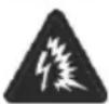 | Damage to the IGBT transistor and the main relay. Disconnect the meter from the tested object in a quick and decisive way to minimize the ignition of the electric arc between the disconnected elements. Send the instrument to the service centre. |
 | You must consult the manual. |
 | The decision of the user is necessary. |
 | Discharging the object |
 | Riso(PV), Riso(AC)Activation of current limit. The symbol displayed is accompanied by a continuous beep. |
| IscCapacitance of the tested object is too high. Activation of current limit. The display of the symbol is accompanied by the message Isc >20A. | |
 | Riso(PV)The measurement was carried out, however without the guaranteed accuracy, because at the time of its performance there were disturbances causing the samples to differ from each other by more than 1%. |
| Riso(AC)The tested object is under the voltage within the range of 10 V...50 V. The measurement is possible, but without guaranteed accuracy.The tested object is under the voltage exceeding 50 V. The measurement is blocked. | |
| RcontThe message that appears after the measurement indicates significant discrepancies between the partial measurements. The measurement result may be affected by a large, unspecified error. | |
| IscMessage displayed after measurement. This indicates significant discrepancies between partial measurements. The measurement result may be affected by a large, unspecified error (usually positive).No data from IRM-1 before and after short-circuit current measurement. | |
 | The meter is ready for measurement. |
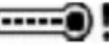 | Maximum temperature of the meter is exceeded. The measurement is blocked. |
AU  RT RT | Automatic measurement activation. |
AI  O O | The test leads compensation is activated for low-voltage resistance measurements. |
| DC-ZERO | Zeroing the current clamps in the DC range. |
| Battery / rechargeable battery status | |
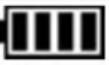 | Charged. |
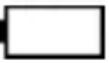 | Discharged. |
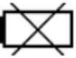 | Fully discharged. The meter switches off automatically. Replace or recharge the batteries. |
SONEL S.A.
Wokulskiego 11
58-100 Świdnica
Poland
Customer Service
tel.+48 74 884 10 53
e-mail: customerservice@sonel.com
www.sonel.com
- USER MANUAL
- PHOTOVOLTAIC METER
- PVM-1020
- CONTENTS
- General information....5
- Quick start 9
- Measurements....14
- Memory of measurement results....39
- Communication....45
- Troubleshooting....46
- Power supply....46
- General information
- Safety symbols
- NOTE!
- General characteristics
- Compliance with standards
- Safety standards:
- Referenced standards
- Quick start
- Turning the meter on and off, display backlight
- Selection of general measurement parameters
- Remembering the last measurement result
- Connectivity between IRM-1 and PVM-1020
- Pairing the meters
- Unpairing
- Automatic completion of results with environmental parameters after regaining connection with the IRM-1
- Measurements
- WARNING
- Insulation resistance
- Measurement of insulation resistance (PV)
- Additional information displayed by the meter
- Measurement of insulation resistance (AC)
- Additional Information
- DC voltage of open circuit U oc
- DC short circuit current I sc
- Automatic measurements (DC)
- Measurement of operating current and power
- Resetting C-PV clamps
- Low-voltage measurement of resistance
- Compensation of test leads resistance - autozeroing
- Low-current measurement of resistance
- Measurement of continuity of protective conductors and equipotential bondings with ±200 mA current
- Diode test with 200 mA current
- Test of blocking diode with 1000 V voltage
- Memory of measurement results
- Recording measurement result data in the memory
- Changing the cell and bank number
- Viewing memory data
- Deleting memory data
- Deleting the selected object and its cells
- Deleting the entire memory
- Communication
- Set of accessories to connect the meter to a PC
- Data transmission using Bluetooth module
- Troubleshooting
- Power supply
- Monitoring the power supply voltage
- Replacing the (rechargeable) batteries
- General rules of using the Nickel Metal Hydride (Ni-MH) batteries
- Cleaning and maintenance
- Storage
- Dismantling and disposal
- Technical data
- Basic information
- DC voltage measurement
- AC True RMS voltage measurement
- Frequency measurement
- Measurement of I_sc short-circuit current
- Measurement of insulation resistance of the module/ PV system
- Measurement of Riso resistance
- Measurement of leakage current
- Measurement of insulation resistance
- Measurement of operating current and power
- Current measurement at power measurement - AC and DC voltage
- Low-voltage measurement of continuity of circuit and resistance
- Measurement of continuity of protective conductors and equipotential bondings with ±200 mA current
- Converting measurement results to STC conditions
- Other technical specifications
- NOTE
- Maximum operating time on one set of batteries
- Conditions
- Maximum operating time on a single battery charge
- Manufacturer
- SONEL S.A.
Brand : Sonel
Model : PVM-1020
Category : Mètre