
DoorPhone AP1 - Intercom Evolveo - Free user manual and instructions
Find the device manual for free DoorPhone AP1 Evolveo in PDF.


| Product Type | Video intercom system |
| Model | Evolveo DoorPhone AP1 |
| Indoor Monitor Display | 7" TFT LCD with touch screen, resolution 1024x600 |
| Outdoor Camera Resolution | 2 MPx, 1080P (H.264) |
| Night Vision | IR illumination up to 7m (850nm) |
| Outdoor Unit Protection | IP65 waterproof |
| Power Supply (Indoor Monitor) | DC 18V / 1000mA (adapter AC 100-240V) |
| Power Consumption (Standby / Active) | Indoor: 1.5W / 10W; Outdoor: 1W / 2W |
| Connection Type | 2-wire without polarity |
| Maximum Cable Length | Up to 120m with 0.75mm² wire |
| Operating Temperature (Indoor / Outdoor) | -10°C to 50°C / -20°C to 60°C |
| Dimensions (Indoor Monitor) | 160 x 240 x 28 mm |
| Dimensions (Outdoor Unit) | 165 x 95 x 45 mm |
| Mounting Height (Outdoor Unit) | 145 - 160 cm |
| WiFi | Built-in WiFi (2.4 GHz) for Smart Life app connection |
| Memory Card Support | microSD up to 128GB |
| RFID Card Reader | Supports up to 600 cards (zone 1: 500, zone 2: 100) |
| Electric Lock Control | Dual relay outputs for 2 locks (electronic or magnetic) |
| Audio Communication | Hands-free two-way voice |
| Call Ring Time | Adjustable: 10, 20, 30, 50, 60 seconds |
| Customizable Ringtones | 6 preset + up to 100 custom MP3 files (max 1MB each) |
| Modes | Home, Away (leave message), Do Not Disturb |
| Smart Life App Compatibility | iOS and Android (remote control and notifications) |
Frequently Asked Questions - DoorPhone AP1 Evolveo
User questions about DoorPhone AP1 Evolveo
0 question about this device. Answer the ones you know or ask your own.
Ask a new question about this device
Download the instructions for your Intercom in PDF format for free! Find your manual DoorPhone AP1 - Evolveo and take your electronic device back in hand. On this page are published all the documents necessary for the use of your device. DoorPhone AP1 by Evolveo.
USER MANUAL DoorPhone AP1 Evolveo
natural_image
Exterior view of a white EVOLVE digital security camera with a central display and control panel (no readable text or symbols beyond branding)
natural_image
Exterior view of a modern digital security camera with display and control buttons (no readable text or symbols)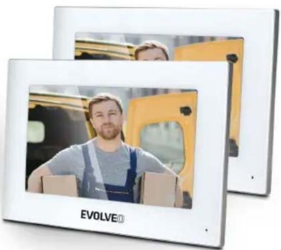
natural_image
Two-framed digital tablets displaying a man in a blue overalls, with a yellow vehicle in the background (no visible text or symbols on the devices themselves)Obsah / Content / Tartalom / Cuprins / Inhalt / Contenuto / Vsebina
Česky....4
Slovensky 29
English....54
Magyar....79
Română 104
CZ
SK
EN
HU
RO
Obsah
ZÁKLADNÍ FUNKCE A MOŽNOSTI SYSTÉMU.... 4
BALENÍ......4
TECHNICKÉ SPECIFIKACE....4
INFORMACE O PRODUKTU EVOLVEO DOORPHONE AP1 6
SCHÉMA STANDARDNÍ SADY AP1....8
INFORMACE O PRODUKTU EVOLVEO DOORPHONE AP2 9
INFORMACE O PRODUKTU 10
SCHÉMA PŘIPOJENÍ 2 MONITORŮ – FUNKCE INTERKOMU.... 10
SCHÉMA PŘIPOJENÍ VÍCE MONITORŮ- FUNKCE INTERKOMU ...... 11
ČTEČKA RFID KARET - NASTAVENÍ 11
NÁVOD K OBSLUZE 13
ROZHRANÍ MONITORU 14
INTERKOM 15
PŘEHRÁVÁNÍ 15
ROZHRANÍ MONITORU 16
NASTAVENÍ 17
OSTATNÍ NASTAVENÍ 20
KROKY OVLÁDÁNÍ VIDEOTELEFONU A INTERKOMU V APLIKACI 21
PŘIDÁNÍ A PŘIPOJENÍ APLIKACE Smart Life 22
JAK SDÍLET "Smart Life" 23
MONTÁŽ MONITORU A VENKOVNÍCH JEDNOTEK.... 24
PŘIPEVNĚNÍ VENKOVNÍ JEDNOTKY AP1 24
PŘIPEVNĚNÍ VENKOVNÍ JEDNOTKY AP2 25
ÚDRŽBA ZAŘÍZENÍ 25
BEZPEČNOSTNÍ UPOZORNĚNÍ...... 25
ODSTRANĚNÍ NEJČASTĚJŠÍCH PROBLÉMŮ 26
ZÁKLADNÍ FUNKCE A MOŽNOSTI SYSTÉMU
EVOLVE
natural_image
Simple line drawing of a rectangular frame with a horizontal line at the bottom (no text or symbols)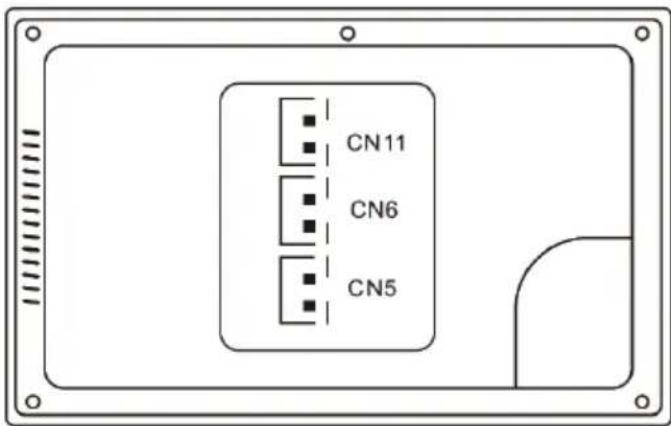
natural_image
Line drawing of a rectangular electronic device with a central screen and labeled button (no text or symbols beyond basic labels)Venkovní jednotka
natural_image
Close-up of a white electronic device with a black remote control panel and a blue key inserted into a square (no visible text or symbols)Hlavní obrazovka
Krok 5: Přidání
Krok 3:
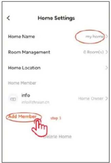
Krok 4:
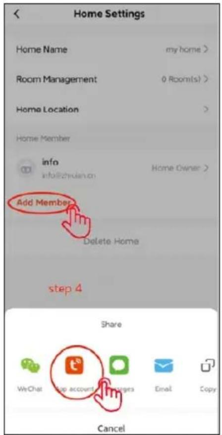
Krok 5:
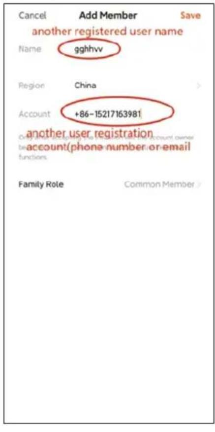
Krok 6:
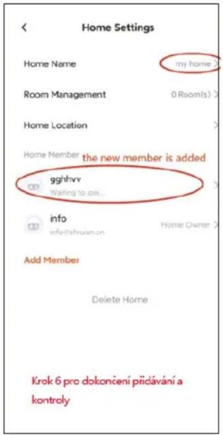
MONTÁŽ MONITORU A VENKOVNÍCH JEDNOTEK
natural_image
Exterior view of a modern office building (no signage)natural_image
Diagram of a device with two panels, one showing a green dashed line and the other a black outline, connected by a vertical tool (no text or symbols present)PŘIPEVNĚNÍ VENKOVNÍ JEDNOTKY AP2
natural_image
Exterior view of a modern office building (no signage)ÚDRŽBA ZAŘÍZENÍ
Copyright © Abacus Electric, s.r.o.
www.evolveo.com
INFORMÁCIE O PRODUKTE 35
SCHÉMA ZAPOJENIA 2 MONITOROV - FUNKCIA INTERKOMU .... 35
SCHÉMA PRIPOJENIA VIACERÝCH MONITOROV - FUNKCIA INTERKOMU ...... 36
ČÍTAČKA KARIET RFID - NASTAVENIA 36
NÁVOD NA OBSLUHU 38
ROZHRANIE MONITORA 39
INTERKOM 40
HRANIE NA 40
ROZHRANIE MONITORA 41
NASTAVENIA 42
OSTATNÉ NASTAVENIA 45
KROKY NA OVLÁDANIE VIDEOTELEFÓNU A INTERKOMU V APLIKÁCII ...... 46
PRIDANIE A PRIPOJENIE APLIKÁCIE SMART LIFE.... 47
AKO ODOSLAŤ "Smart Life" 48
INŠTALÁCIA MONITORA A VONKAJŠÍCH JEDNOTIEK 49
PRIPEVNENIE VONKAJŠEJ JEDNOTKY AP1.... 49
PRIPEVNENIE VONKAJŠEJ JEDNOTKY AP2....50
ÚDRŽBA ZARIADENÍ 50
BEZPEČNOSTNÉ UPOZORNENIE....50
OPRAVA NAJČASTEJŠÍCH PROBLÉMOV 51
ZÁKLADNÉ FUNKCIE A MOŽNOSTI SYSTÉMU
EVOLVE®
natural_image
Simple line drawing of a rectangular frame with a horizontal line at the bottom (no text or symbols)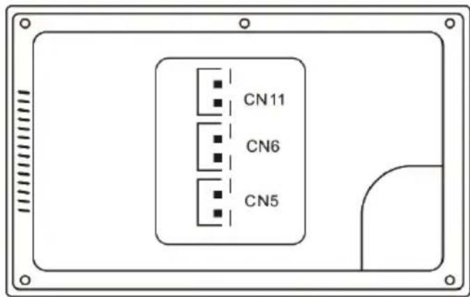
CN11: Pripojenie k napájaniu DC 18 V.
natural_image
Line drawing of a rectangular electronic device with a central screen and control buttons (no text or symbols)Vonkajšia jednotka
INFORMÁCIE O PRODUKTE
▶ ID našej stanice (SW4 Dip setting).
| PREPÍNAČ DIP | ID stanice ourdoor | PREPÍNAČ DIP | ID stanice ourdoor | ||
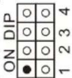 | 1 | 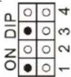 | 5 | ||
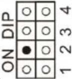 | 2 | 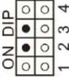 | 6 | ||
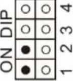 | 3 | 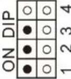 | 7 | ||
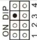 | 4 | ||||
SCHÉMA ZAPOJENIA 2 MONITOROV - FUNKCIA INTERKOMU
natural_image
Close-up of a white electronic device with a black remote control panel and a blue key inserted into a square slot (no visible text or symbols)Hlavná obrazovka
1) Monitor -
fotografovanie/videozáznam, volanie,
prepínanie, monitorovanie
2) Interkom - volanie a interkom s inými monitormi
3) Záznamy - uložené fotografie a videá
4) Režim - 3 režimy, Domov, Opustit' domov, Spánok
Doma - po stlačení vonkajšieho tlačidla monitor zvoní 30 sekúnd a potom odošle upozornenie
Vonkajšie tlačidlo Home - po stlačení vonkajšieho tlačidla sa ozve hlas z vonku a povie "Leave message" (Zanechajte správu).

Krok 4: zariadenie wifi je nájdené a kliknite na tlačidlo "pridat"
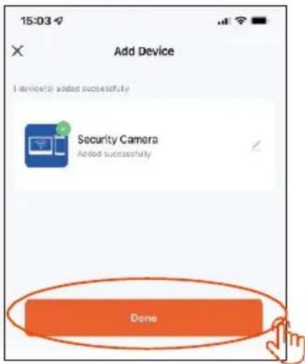
Krok 6: úspešne pridané a kliknite na tlačidlo "Hotovo"
Krok 7: Nastavenie režimu po pridaní zariadenia
Krok 3:
Krok 4:
Krok 5:
Krok 6:
INŠTALÁCIA MONITORA A VONKAJŠÍCH JEDNOTIEK
natural_image
Exterior view of a modern office building (no signage)natural_image
Diagram of a device with a vertical panel and a side panel, showing alignment lines (no text or symbols)PRIPEVNENIE VONKAJŠEJ JEDNOTKY AP2
natural_image
Exterior view of a modern office building (no signage)ÚDRŽBA ZARIADENÍ
Copyright © Abacus Electric, s.r.o.
www.evolveo.com
BASIC FUNCTIONS AND OPTIONS OF THE SYSTEM....54
PACKAGING....54
TECHNICAL SPECIFICATIONS....54
PRODUCT INFORMATION EVOLVEO DOORPHONE AP1 56
DIAGRAM OF STANDARD SET AP1....58
PRODUCT INFORMATION EVOLVEO DOORPHONE AP2 59
PRODUCT INFORMATION 60
CONNECTION DIAGRAM OF 2 MONITORS - INTERCOM FUNCTION......60
MULTI-MONITOR CONNECTION SCHEME - INTERCOM FUNCTION ...... 61
RFID CARD READER - SETTINGS 61
OPERATING INSTRUCTIONS....63
MONITOR INTERFACE 64
INTERKOM 65
PLAYING 65
MONITOR INTERFACE 66
SETTINGS....67
OTHER SETTINGS....70
STEPS TO CONTROL THE VIDEOPHONE AND INTERCOM IN THE APP ....71
ADDING AND CONNECTING A SMART LIFE APP 72
HOW TO SEND "Smart Life" 73
INSTALLATION OF MONITOR AND OUTDOOR UNITS 74
ATTACHING THE OUTDOOR UNIT AP1....74
ATTACHING THE OUTDOOR UNIT AP2....75
EQUIPMENT MAINTENANCE 75
SAFETY NOTICE 75
FIXING THE MOST COMMON PROBLEMS....76
BASIC FUNCTIONS AND OPTIONS OF THE SYSTEM
- communication of the owner with visitors
• increased security of the house
• electric door lock control
• visual check of the visitor before entering the house - infrared illumination of the area in front of the camera ensuring a clear image even in 0 Lux lighting
- 7" TFTLCD display
- Hands free communication
- choice of ringtones
- the possibility of hanging the videophone on the wall
PACKAGING
After opening the box, it is recommended to check the contents according to the following list:
• monitor (In case of AP2 model, 2 monitors are included)
- mounting frame for monitor
- fixing screws
- door camera unit
- mounting frame for surface mounting of the camera unit + gasket
• power supply (2 power supplies included for AP2)
• cables fitted with connectors for interconnection.
TECHNICAL SPECIFICATIONS
Indoor unit
- 7" LCD monitor with touch screen
● Power adapter: Input: AC 100-240V Output: DC 18V 1000mA - Standby power consumption 1.5W and working mode 10W
- Connection: 2 PINS
● Monitoring time: 30 seconds - Operating temperature: -20^ - +60^
- Dimensions (h/w/h): 160 x 240 x 28mm
Outdoor unit
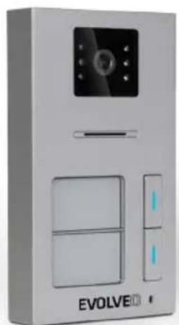
- Single button door station - brushed aluminium
● Professional CCD camera with IR illumination -
Standby/operating mode 1W
-
Night light: 7m - IR LED 850nm
- Operating temperature -20^ - +60^
- Mounting height: 145 – 160cm
- Dimensions (h/w/h): 165 x 95 x 45mm
EVOLVE®
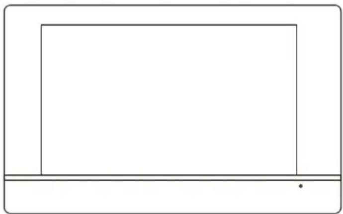
Indoor Wifi monitor
1) System: Linux
2) Connection method: 2 wires without polarity, diameter 0.75 mm2
3) Functions: Video communication, monitor, unlocking
4) Resolution: 1024*600
5) Method of communication: Two-way voice
6) Call time: 60 seconds
7) Power input: 6W; standby: 2,5W
8) memory/video card, WiFi
9) Working voltage: DC 18-24V
10) Working temperature: -10°C - 50°C
11) Maximum capacity: 128GB
natural_image
Simple line drawing of a rectangular frame with a horizontal line at the bottom (no text or symbols)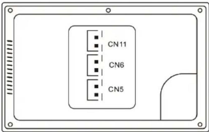
CN11: Connection to DC 18V power supply.
CN6: Connection to outdoor/door unit or other indoor monitor
CN5: Connecting to an internal monitor.
PRODUCT INFORMATION EVOLVEO DOORPHONE AP1
natural_image
Line drawing of a rectangular electronic device with a central screen and control buttons (no text or symbols)Outdoor unit
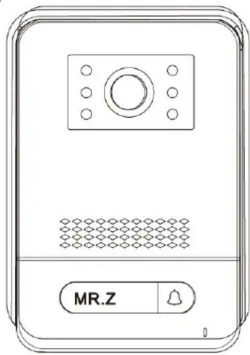
1) Title: Outdoor/Door stations
2) Resolution: 2MPx 1080P
3) Video streaming: H.264
4) Communication: Two wires without polarity
5) Functions: Video and Audio transmission
6) Call time: 60 seconds
7) Waterproof: IP65
8) Night vision: yes
9) Standby: 1W
10) Work performance: 2W
11) Voltage: DC 18-24V
12) Working temperature: -10°C - 50°C
13) Connection: 2 wires without polarity
14) Locks: 2x relays
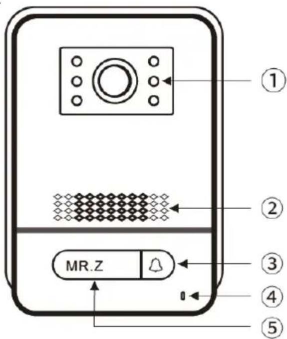
Front view
jumper 2: connect as CN3 power output, disconnect as CN3 without power output.
jumper 1: disconnection as CN3 for connection of electronic lock.
jumper 3: for door station ID, connection as id 1, disconnection as id 2.
CN1: for the lock end button CN3.
CN2: for the lock end button CN4.
CN3: To lock 1 (the door station can offer power to the electronic lock, the magnetic lock must be connected to an external power source).
CN4: To lock 2 (lock must be connected to external power supply, NO and COM connected to magnetic lock, NC and COM connected to electronic lock).
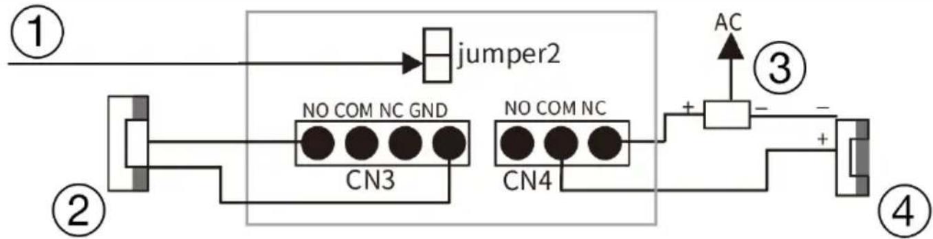
flowchart
graph TD
    A["①"] --> B["jumper2"]
    B --> C["②"]
    C --> D["NO COM NC GND"]
    D --> E["③"]
    E --> F["NO COM NC"]
    F --> G["④"]
    G --> H["AC"]
    style A fill:#f9f,stroke:#333
    style B fill:#ccf,stroke:#333
    style C fill:#cfc,stroke:#333
    style D fill:#ffc,stroke:#333
    style E fill:#fcc,stroke:#333
    style F fill:#cff,stroke:#333
    style G fill:#ffc,stroke:#333
Detailed connection With the lock diagram
1) connection as Output power
2) electric lock
3) power supply
4) Magnetic lock
(1 outdoor station for 1 indoor monitor)
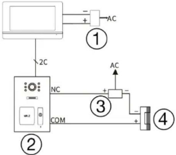
flowchart
graph TD
    A["Monitor"] -->|2C| B["Two Monitors"]
    B --> C["AC"]
    B --> D["COM"]
    C --> E["AC"]
    D --> F["AC"]
    style A fill:#f9f,stroke:#333
    style B fill:#ccf,stroke:#333
    style C fill:#cfc,stroke:#333
    style D fill:#fcc,stroke:#333
    style E fill:#ffc,stroke:#333
    style F fill:#fcc,stroke:#333
1) power adapter
2) outdoor stations
3) power supply
4) Magnetic lock
Detailed connection diagram
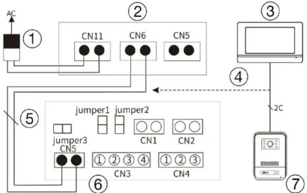
flowchart
graph TD
    A["AC"] --> B["①"]
    B --> C["CN11"]
    B --> D["CN6"]
    B --> E["CN5"]
    C --> F["jumper1"]
    D --> G["jumper2"]
    E --> H["jumper3"]
    F --> I["⑥"]
    G --> J["⑦"]
    H --> K["⑤"]
    K --> L["②C"]
    L --> M["③"]
    M --> N["④"]
    N --> O["⑦"]
1) input/adapter
2) internal monitor rear view
3) internal monitor
4) connection detail 2 wires
5) 2 wires
6) Outdoor unit connectors
7) outdoor stations
Remark: 18V1A adapter as power supply:
- Diameter 0,2 mm 2 wires - cable length max 40 meters.
- Diameter 0,5 mm 2 wires - cable length max 80 meters.
- Diameter 0,75 mm 2 wires - cable length max 120 meters.
PRODUCT INFORMATION EVOLVEO DOORPHONE AP2
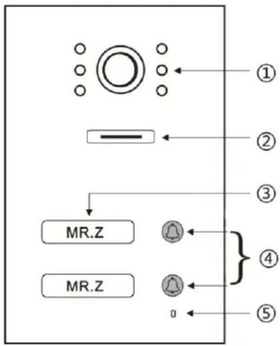
Front view
View of the outdoor station
1. NO 2. COM 3. NC 4. GND
CN3: To lock 1 (the door station can power the electronic lock, the magnetic lock must be connected to an external power supply).
CN4: To lock 2 (the lock must be connected to an external power source, NO and COM are connected to the magnetic lock, NC and COM to the electronic lock).
CN5: Connecting to an internal monitor
CN1: Lock control button 1 (CN3). Button directly controls the lock without an app or internal unit - any button can be used
CN2: Lock control button 2 (CN4) This button directly controls the lock without an application or internal unit - any button can be used.
SW1: disconnection as CN3 for connection of electronic lock.
SW2: connect as CN3 power output, disconnect as CN3 without power output.
SW4: Our station ID.
K1: RFID card learning button
PRODUCT INFORMATION
▶ Our station ID (SW4 Dip setting).
| DIP SWITCH | Station ID ourdoor | DIP SWITCH | Station ID ourdoor | ||
| 1 | | 5 | ||
| 2 | | 6 | ||
| 3 | | 7 | ||
| 4 | ||||
CONNECTION DIAGRAM OF 2 MONITORS - INTERCOM FUNCTION
(1 outdoor station for max. 2 indoor monitors)
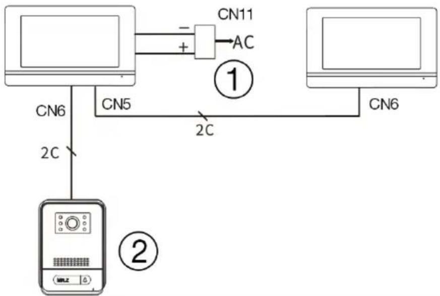
flowchart
graph TD
    A["Computer"] -->|CN5| B["Switch"]
    B -->|CN6| C["Server"]
    A -->|CN11| D["AC"]
    D -->|CN11| E["Computer"]
    B -->|CN5| F["Switch"]
    F -->|CN6| G["Server"]
    style A fill:#f9f,stroke:#333
    style B fill:#ccf,stroke:#333
    style C fill:#cfc,stroke:#333
    style D fill:#fcc,stroke:#333
    style E fill:#ffc,stroke:#333
    style F fill:#cff,stroke:#333
    style G fill:#ffc,stroke:#333
1) power adapter
2) outdoor stations
Remark: 18V1A adapter as central power supply:
- Diameter 0,2 mm 2 wires max length 20 meters.
- Diameter 0,5 mm 2 wires max length 50 meters.
- Diameter 0,75 mm 2 wires max length 100 meters
(2 outdoor stations for max. 4 indoor monitors)
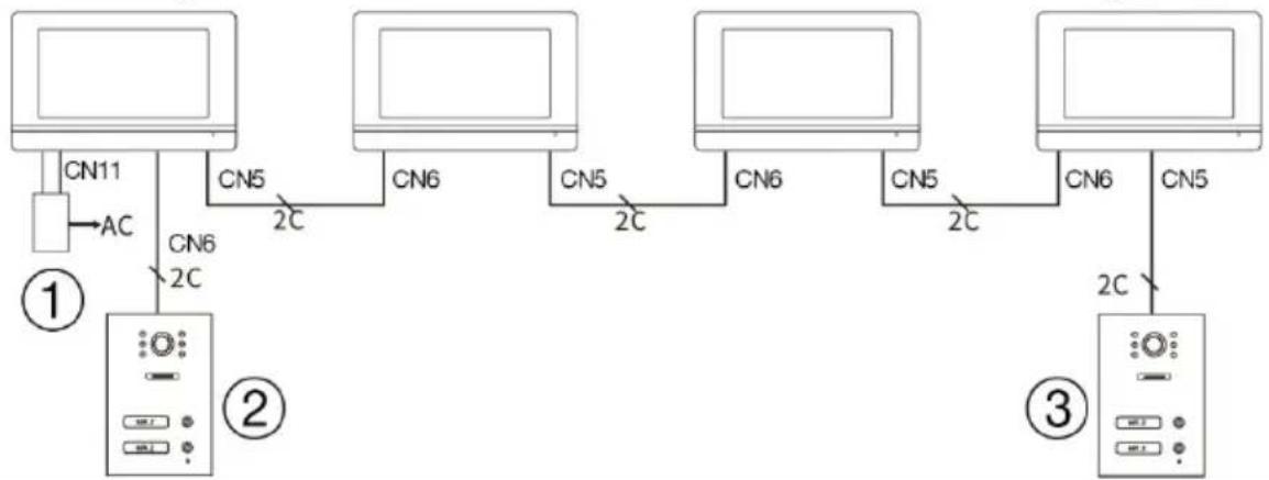
flowchart
graph TD
    A["①"] -->|CN11 AC| B["②"]
    B -->|CN5 2C| C["③"]
    B -->|CN6 2C| D["③"]
    B --> E["CN5 2C"]
    B --> F["CN6 2C"]
    B --> G["CN5 2C"]
1) power supply
2) outdoor stations
3) outdoor stations
Remark: 18V1A adapter as central power supply:
- Diameter 0,2 mm 2 wires max length 20 meters.
- Diameter 0,5 mm 2 wires max length 50 meters.
- Diameter 0,75 mm 2 wires max length 100 meters.
RFID CARD READER - SETTINGS
Steps for setting up access control to the outdoor station:
2 zones for learning RFID cards, zone 1 for 500 contactless cards, zone 2 for 100 contactless cards.
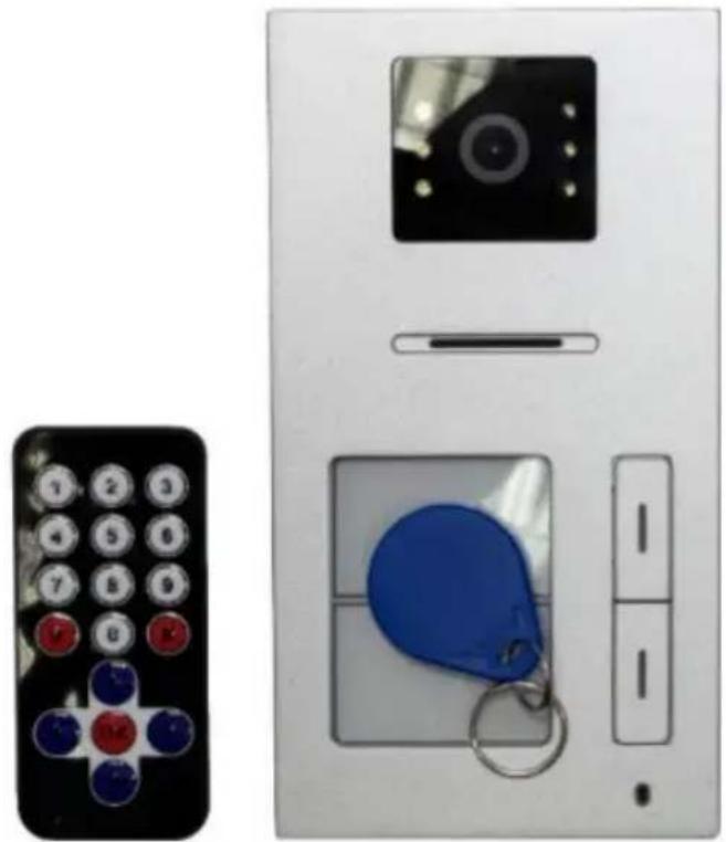
natural_image
Close-up of a white electronic device with a black remote control panel and a blue keychain, no visible text or symbols.- To enter setup mode: use the IR remote near the door station reader, then press *# 1234 # to enter setup mode (factory default password 1234).
2. Setting up cards in zone 1
a. Enter setup mode
b. Adding cards: press button 1 on the controller (a long "biii..." sound), attach the RFID (a short "bi" sound indicates successful addition). Press ** to exit (if the "bibi" sound is heard, it means the card has already been used".
c. To remove zone 1 cards: press 2 on the controller, attach the RFID card you want to remove to the door unit, press ** to exit.
3. Setting up cards in zone 2
a. Enter setup mode
b. Adding cards: press button 7 on the controller (a long "biii..." sound), attach the RFID (a short "bi" sound indicates successful addition). Press ** to exit (if the "bibi" sound is heard, it means the card has already been used".
c. To remove zone 2 cards: press 2 on the controller, attach the RFID card you want to remove to the door unit, press ** to exit.
4. Setting up the Administrator card and adding cards using the Administrator card
a. Enter setup mode
b. To add an admin card for zone 1: press 00 on the controller, attach one card as an admin card, press ** to exit. And then attach administrator card 1 and then a new user card. To finish adding, reattach the administrator card.
c. To add an admin card for zone 2: press 33 on the controller, attach one card as an admin card, press ** to exit. And then attach administrator card 1 and then a new user card. To finish adding, reattach the administrator card.
d. To set up admin delete cards: press 66, swap one card as admin delete card, press ** to exit. Attach the administrator card for deletion and the user card for zooming. Card ID for deletion. Finally, swap the admin tab for delete to exit.
5. Delete all cards
a. Enter setup mode
b. Enter 99 to delete all cards. 5 seconds later a long bi...tone is heard, indicating a successful deletion.
6. Change the default password
a. Enter setup mode
b. Press 8 and then enter 4 digits as the new password for the settings. Press # to confirm. And then enter the same new password and confirm the # again. Press ** to exit.
7. K1 button settings
a. Restore the factory default password
i. Press the K1 switch on the back of the door station and charge the power until the bi tone sounds.- The password is reset to factory 1234
b. Administrator card settings
i. Enter setup mode
ii. Press K1 once and attach a new Zone 1 Administrator card.
iii. Press K1 a second time and attach a new Zone 2 Administrator card.
iv. Press K1 a third time and insert the administrator card to delete the cards
v. Press switch K1 a fourth time to exit.
OPERATING INSTRUCTIONS
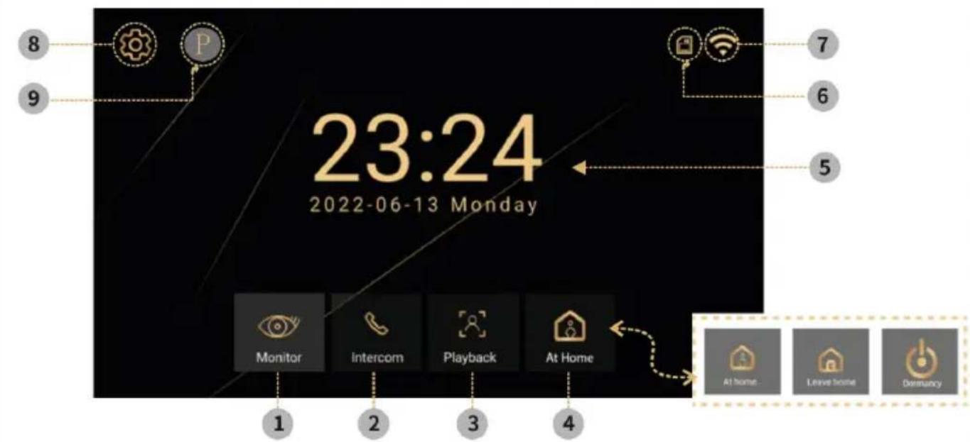
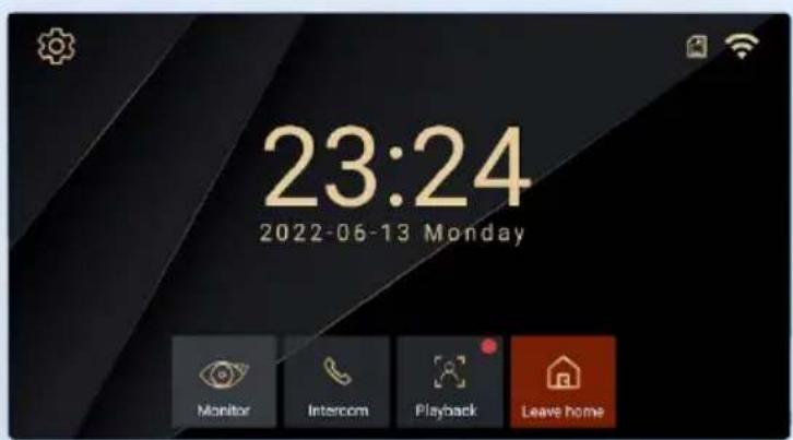
Main screen
1) Monitor - take picture/video, call, switch, monitor
2) Intercom - calling and intercom with other monitors
3) Logs - Saved photos and videos
4) Mode - 3 modes, Home, Leave Home, Sleep
5) Time and date display
6) SD memory card status
7) Stav Wifi
8) Settings - Ringtone settings, Room ID settings, Time settings, Screen saver, Other
9) P- User manual
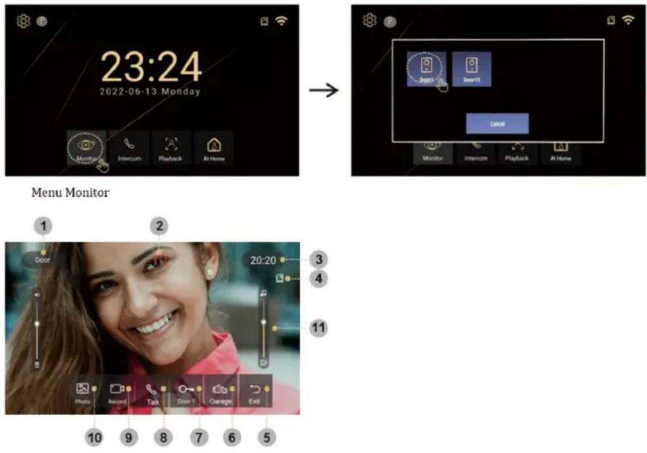
1) Selected door stations
2) Monitor and call time countdown
3) System time
4) SD memory card status
5) Termination/Return
6) Unlocking the door 2
7) Unlocking the door 1
8) Reply
9) Record
10) Images
11) Setting the ringer volume
INTERKOM
When you have multiple internal monitors, you can use the intercom mode to call between them. Just press the intercom button and select the selected unit. The following describes the different states in which the intercom can be. For the intercom function, the same room ID must be set on all monitors you want to communicate with.
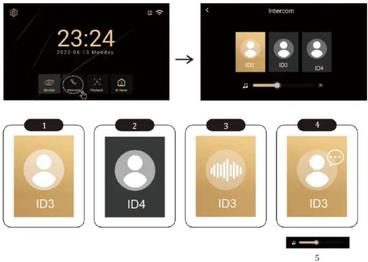
Image and video can be enlarged
MONITOR INTERFACE
Modes (At home, Away from home, Do not disturb)
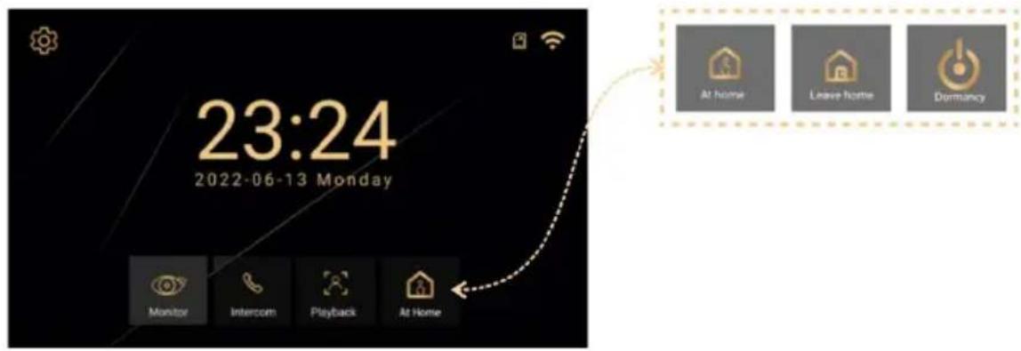
At home - When the outdoor button is pressed, the monitor rings for 30 seconds and then sends an alert
Outside Home - when the outside button is pressed, a voice outside will say "Leave message" leave a message
Do not disturb - for when you don't want to be disturbed. When the outside button is pressed without a ringing tone. Only a visual alert for 30s on the display, then sends an alert.
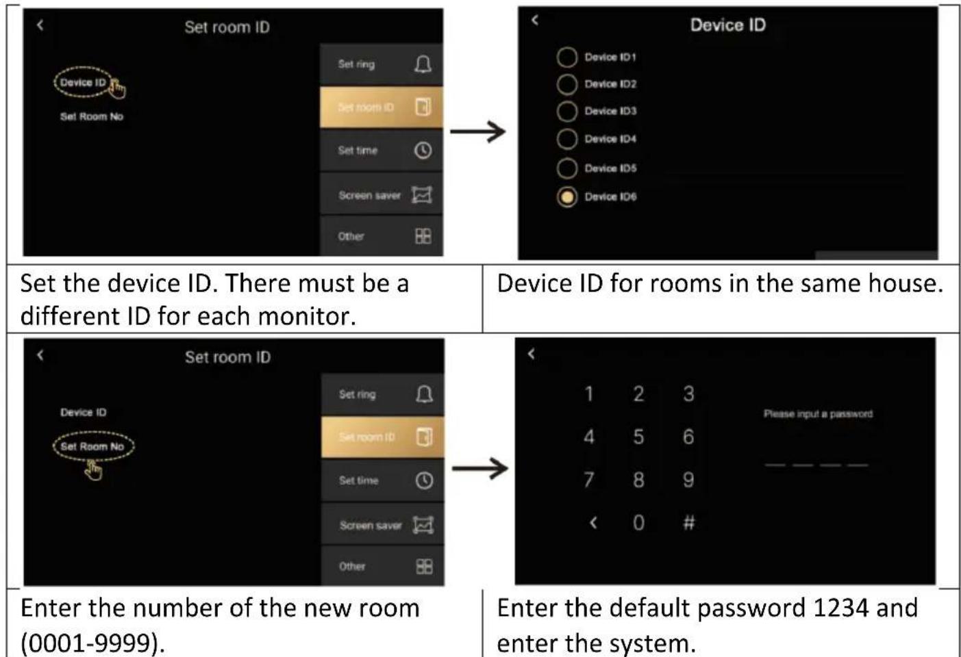
ID settings
SETTINGS
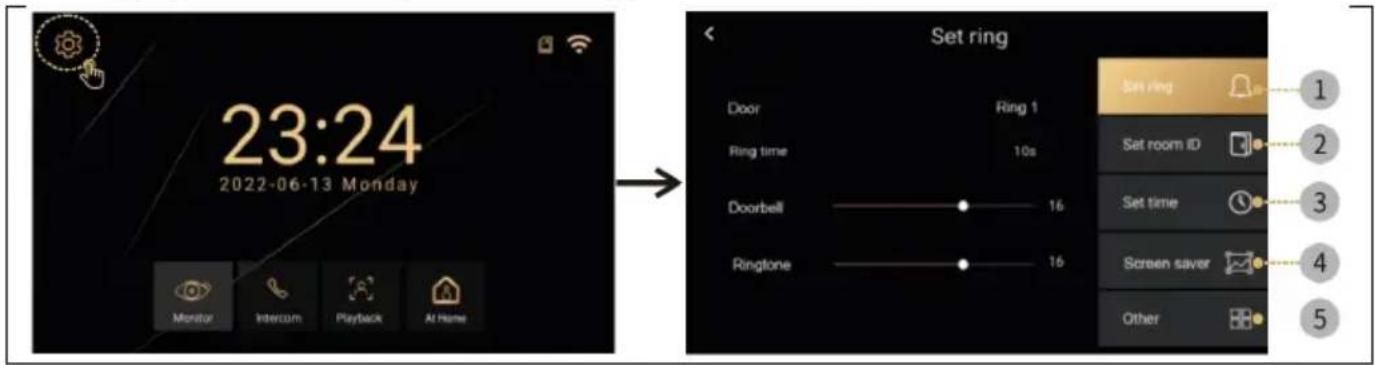
Selecting the ⚙️ icon will open a menu with the following items Set Ringer, Set Room ID, Time Setting, Screen Saver, Other
Ringtone settings
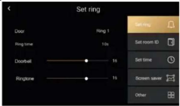
- The door: There are six preset ringtones or you can insert your own ringtones. On the SD card create a folder "ring", The names of the individual files must be 1,2,3.mp3. Files must be mp3 files. Maximum size 1MB. Maximum 100 custom tones can be inserted
• Ringing time: 10,20,30,50,60 seconds. - Doorbell: outdoor unit volume 0-100%.
- Prompt: for outdoor station sound volume 0-100%.
Time settings
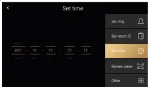
- Time and date settings (when connected to the internet, the system automatically updates the local network time).
Screensaver
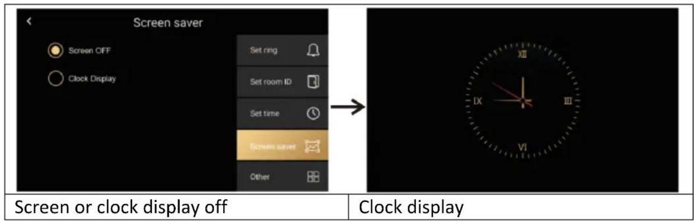
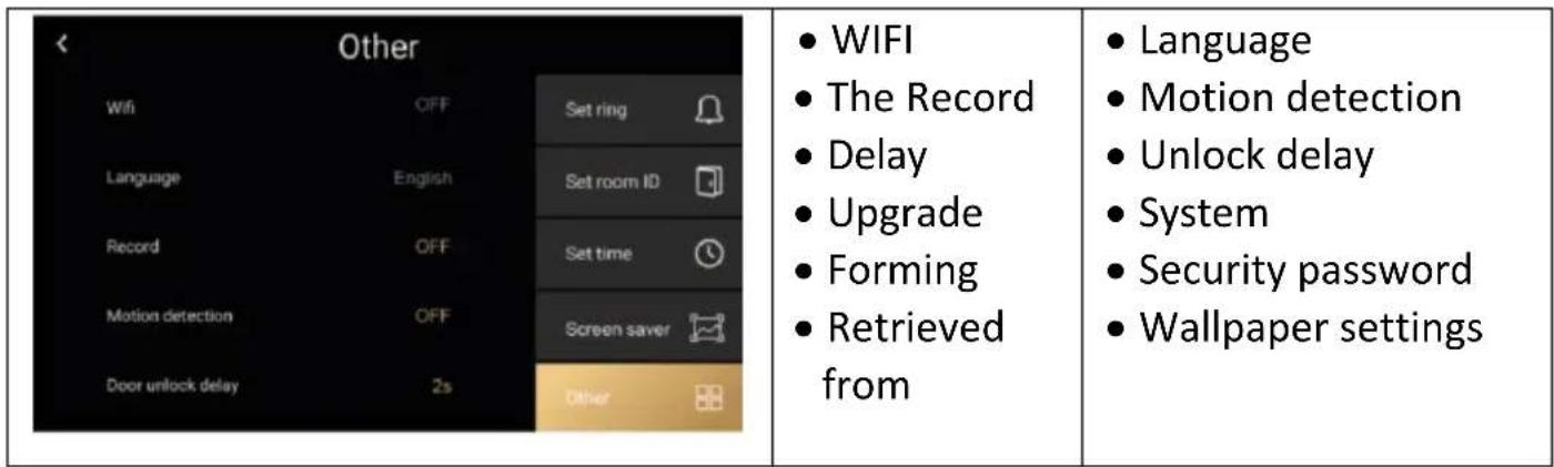
Other
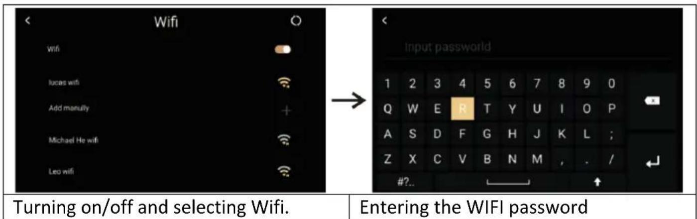
Other > Wifi
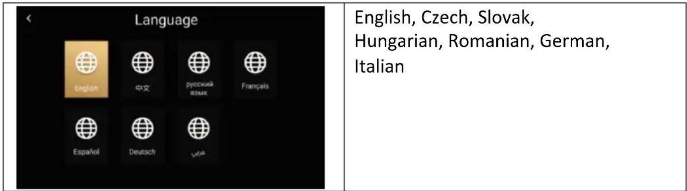
Other > Language
Other > System
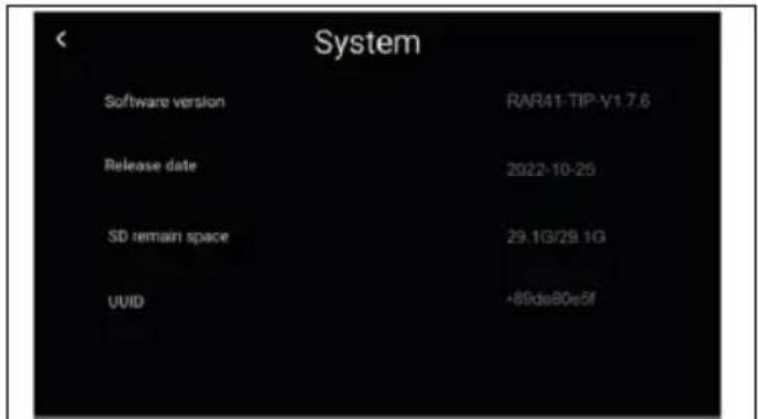
System information: software version, SD card status and device ID can be displayed
Other > Forming
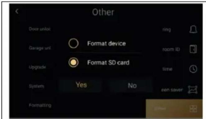
You can format the memory card and restore the factory settings of the internal monitor.
Other > Security password
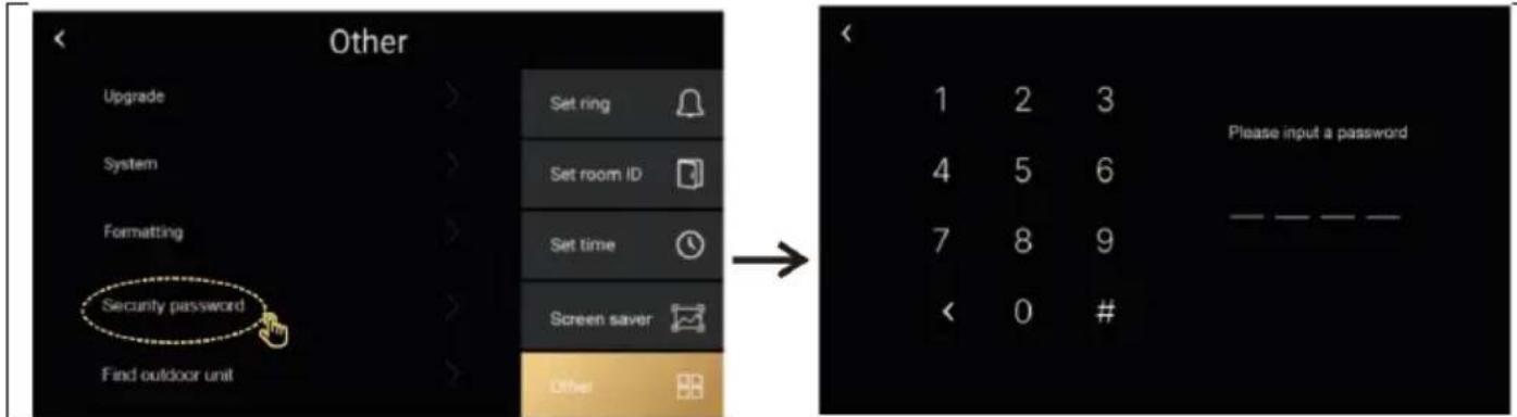
The security password is for the service, users do not have to work with it.
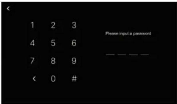
Default password 1234.
Other / Find an outdoor unit
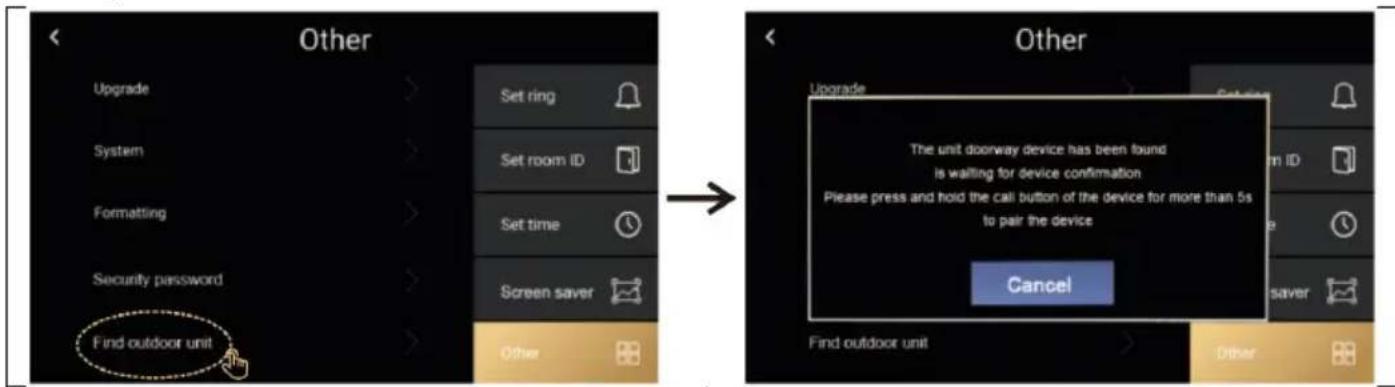
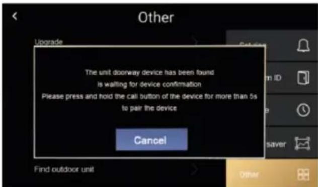
Press the call button of the second door station for more than 5 seconds to pair with the monitor. Until the pairing is complete, exit will be displayed
OTHER SETTINGS
- Recording: select the recording method: Photo, Video, or Off - depending on the setting, the image is recorded when the outdoor unit button is pressed.
- Motion detection: Turns on motion detection in front of the camera, valid only for the door unit set as number 1.
- Update: Used for service purposes, it is necessary to have a file with the latest FW version
- Wallpaper settings: You can insert your own file and use it as a wallpaper on your monitor. Create a folder called "picture" on the SD card of your device and insert*.jpg files with 1024*600 resolution into it. Each image must have a title 1*jpg, 2.jpg and a maximum size of 1 MB. A maximum of 100 files can be uploaded.
STEPS TO CONTROL THE VIDEOPHONE AND INTERCOM IN THE APP
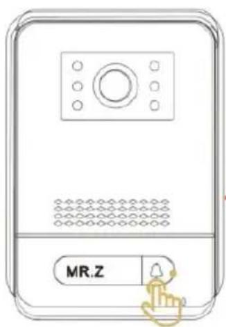
Step 1: Calling from an outdoor station When you make a call, the monitor rings, the picture is displayed and the mobile phone notification rings.
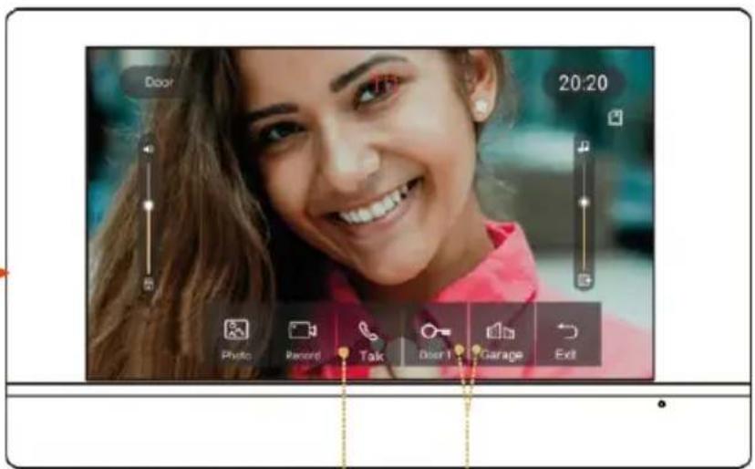
Step 2: Image on monitor display, Press call button to call, press again to close.
Step 3: Press the door to unlock lock 1 or lock 2
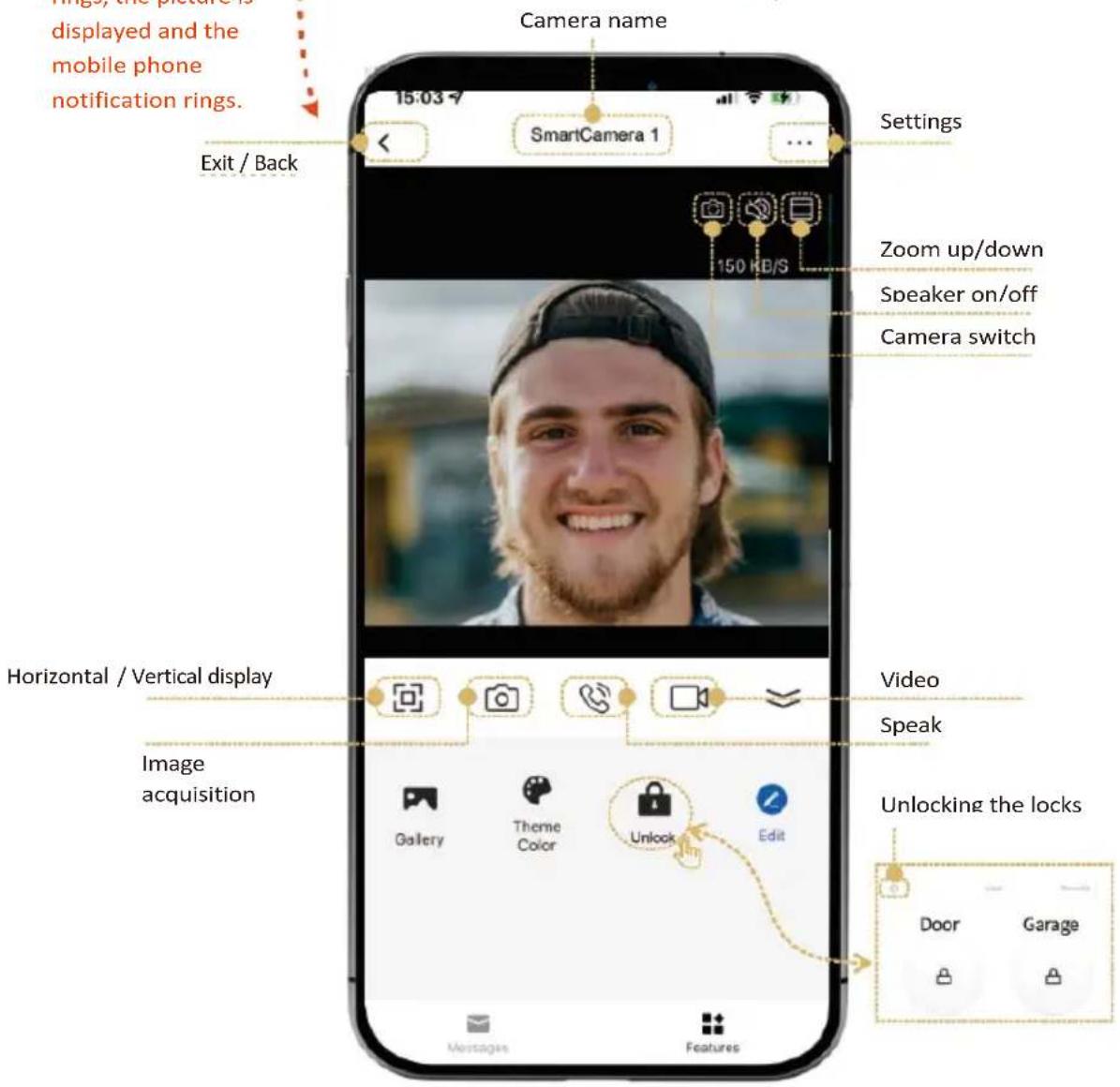
ADDING AND CONNECTING A SMART LIFE APP
Setting up the Smart Life APP for your mobile phone. Make sure the mobile phone is close to the monitor and the 2.4GHz wifi router.
Step 1: Connect the mobile phone to the same wifi with the wifi monitor. And download the "SmartLife" app on GooglePlay or in the iOS app store.
Step 2: click on the "SmartLife" app to add
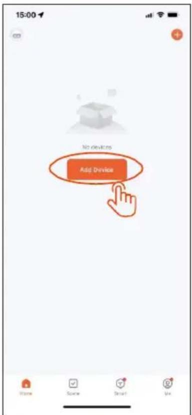
Step 3: Search and pairing
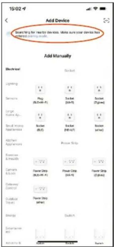
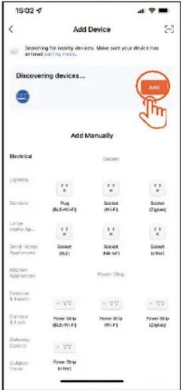
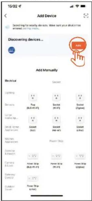
Step 4: the wifi device is found and click "add"
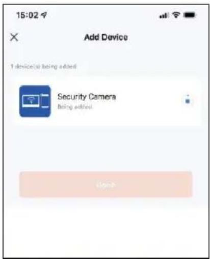
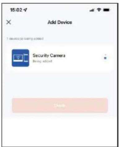
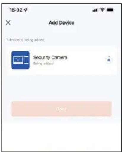
Step 5: Adding
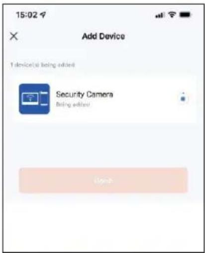
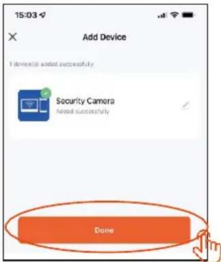
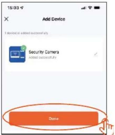
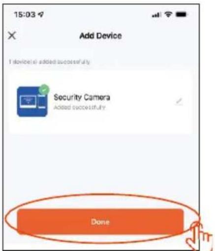
Step 6: successfully added and click "Done"
Step 7: Setting the mode after adding a device
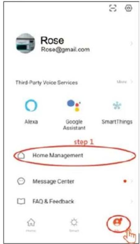
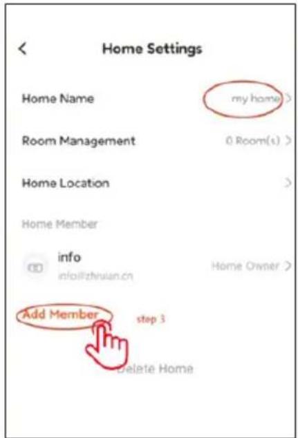
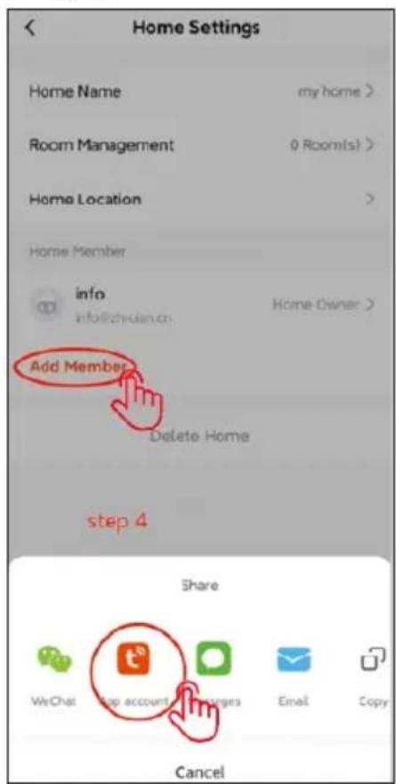
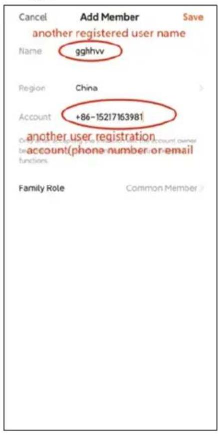
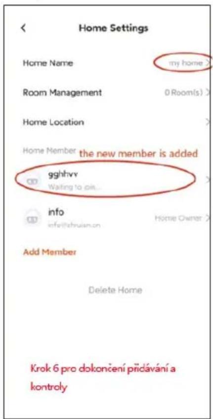
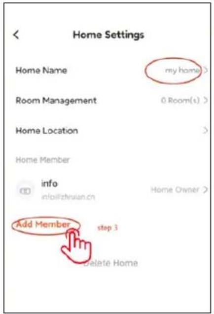
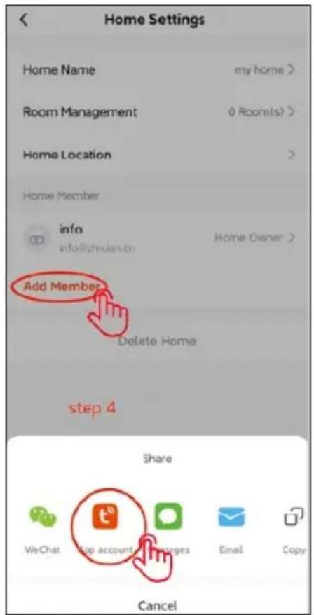
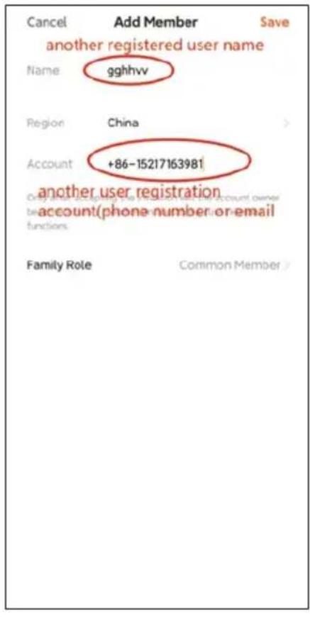
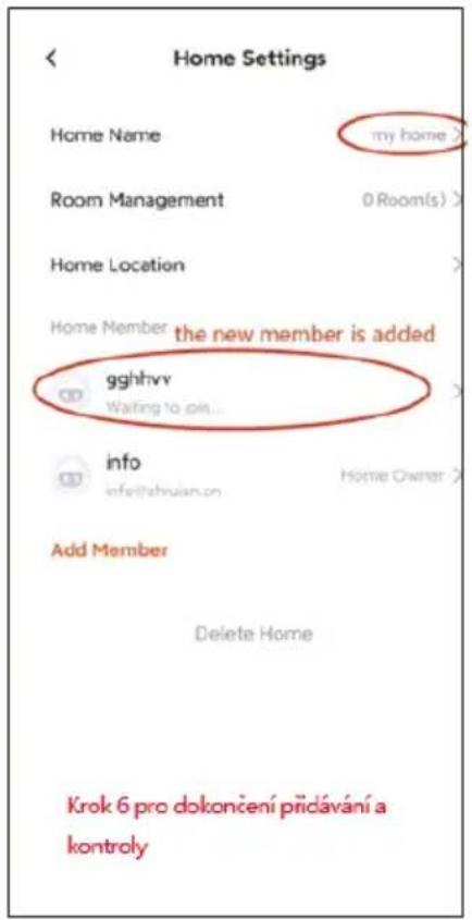
New users must register a new account
Step 1:
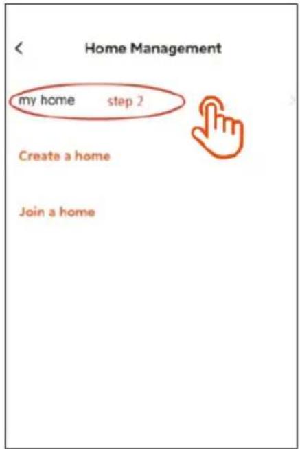
Step 2:
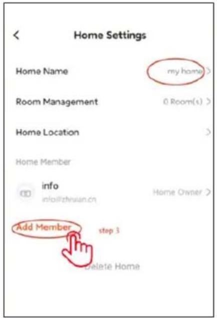
Step 3:
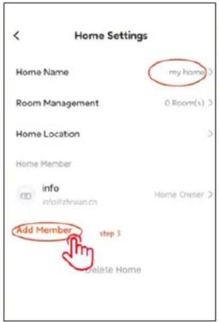
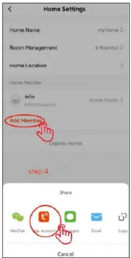
Step 4:
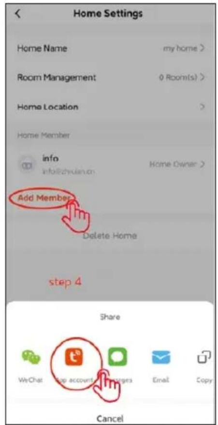
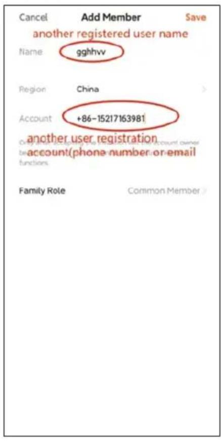
Step 5:
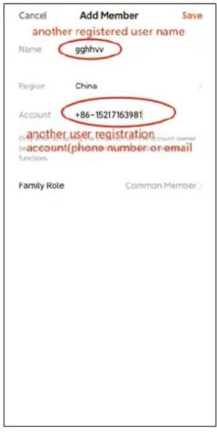
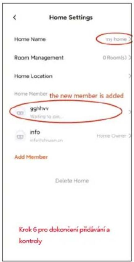
Step 6:
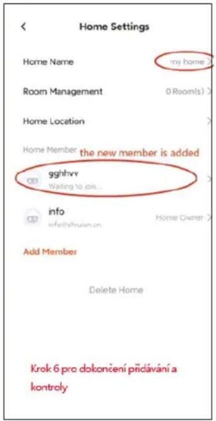
INSTALLATION OF MONITOR AND OUTDOOR UNITS
The package also includes a set for fixing screws and dowels.
Use the fixing frames as a template to mark the holes to be drilled.
For mounting the indoor monitor, the KU 68 wiring box can be used, which has a distance of screw holes identical to the metal monitor bracket.
Outdoor unit AP1 - also allows mounting directly on the wiring box KU 68.
natural_image
Exterior view of a modern office building (no signage)Warning: When installing outdoor units, always use the supplied rubber gaskets as shown in the following illustrations. Always secure outdoor units with screws. In the package you will find a Torx for easy fixing.
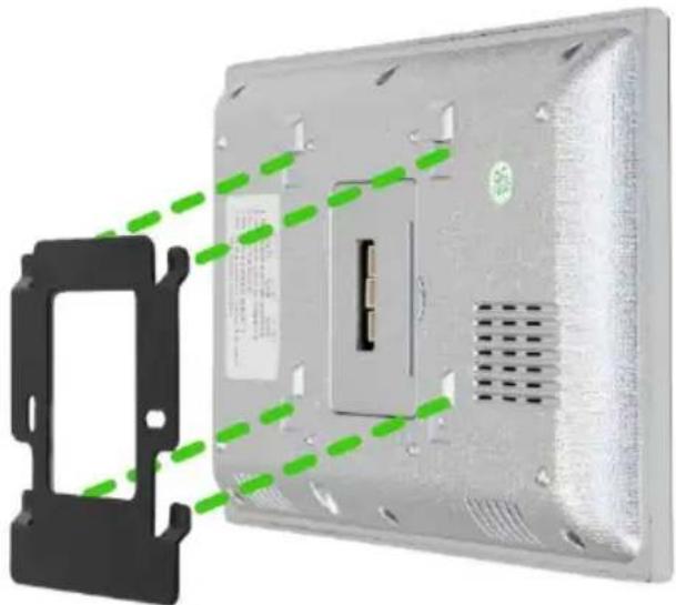
Attaching the monitor to the bracket.
Carefully slide the monitor onto the tabs shown and push downwards.
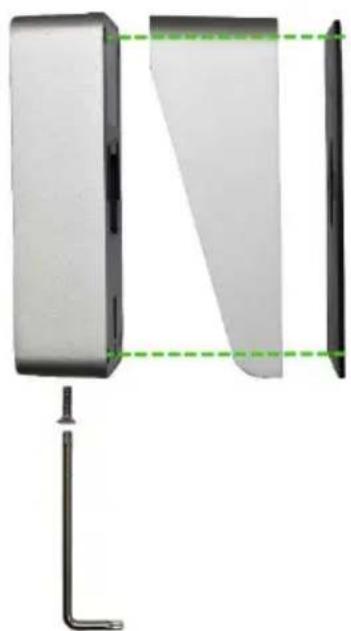
ATTACHING THE OUTDOOR UNIT AP1
Follow the picture below. After sliding the outdoor unit into the frame, secure from the bottom with the screw provided. Always use the supplied gaskets for installation.
natural_image
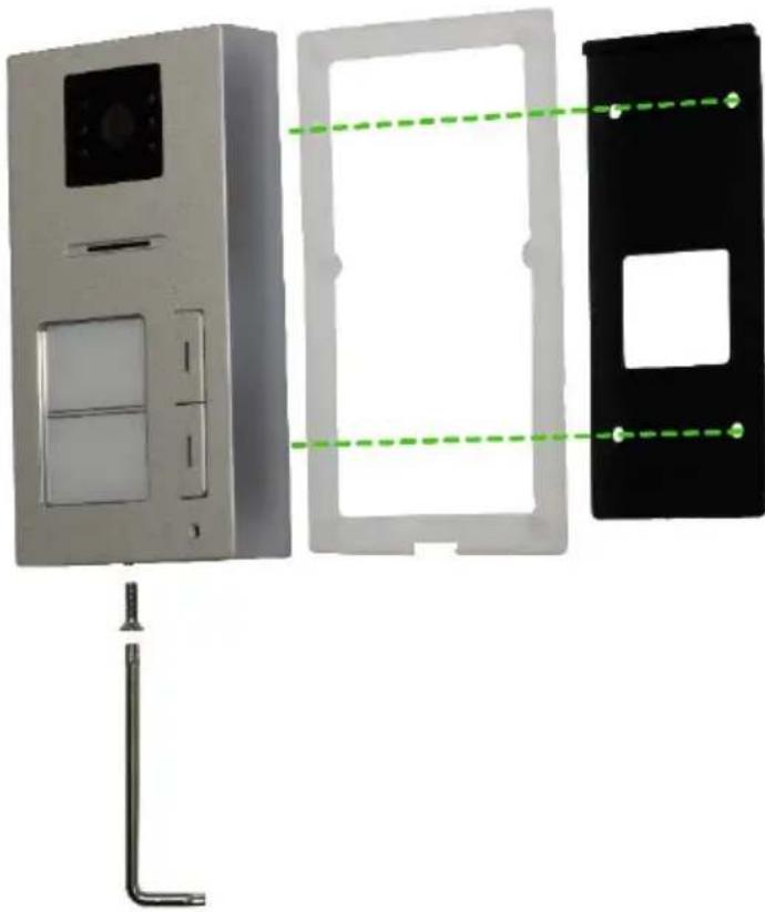
Diagram of a device with two panels, one showing a green dashed line and the other a black outline, connected by a vertical line (no text or symbols present)ATTACHING THE OUTDOOR UNIT AP2
Follow the picture below. After sliding the outdoor unit into the frame, secure from the bottom with the screw provided. Always use the supplied gaskets for installation.
natural_image
Exterior view of a modern office building (no signage)EQUIPMENT MAINTENANCE
The monitor is low maintenance. It is recommended to wipe the device with a damp cloth occasionally, depending on the degree of soiling.
Attention! - The device must be disconnected from the mains adapter before cleaning.
SAFETY NOTICE
- Do not place the videophone near TV receivers or in an environment with high temperature or humidity
- Do not disassemble the monitor or door station
- in direct sunlight into the lens of the door station the image on the video monitor may become unreadable
- Do not expose the device to vibrations and drops
FIXING THE MOST COMMON PROBLEMS
Monitor unresponsive/black screen
Make sure the monitor is properly connected to the original adapter. If so, use a multimeter to measure whether the correct voltage of 18V is present at the output of the adapter. If you do not measure any voltage at the output, check if the adapter socket is energized. If so, the adapter is defective. Visit www.evolveo.com here to order a new one or to file a claim.
Device does not have clear picture/sound, does not ring
Hang the monitor or door panel and connect it with a short cable to avoid breaking the wire in the house. Next, check the picture and sound settings (brightness, contrast, colour, volume).
The lens is dewing
This phenomenon occurs especially in the cold season, when condensation occurs due to the temperature difference between the wall and the door station itself. In case of condensation, we recommend to dry the station thoroughly and adjust the installation.
Spontaneous ringing
Spontaneous ringing causes moisture to enter the camera. The water short-circuits the contacts of the lock switch and the device rings spontaneously. We recommend disassembling the door station, drying it thoroughly and spraying it with a water-repellent electronics varnish.
Whistling (feedback)
The source of the feedback is the splintering of the outgoing sound of the door station. The sound is fragmented and returned to the microphone where it is further amplified. This can be eliminated by lowering the speaker volume.
It doesn't open the lock
Check the integrity of the wiring. Use a multimeter to measure the voltage at the terminals of the lock. The lock requires 12 V to trigger. If this value is lower, we recommend using stronger wires to operate the lock.
Sudden drop in microphone sensitivity
Check the microphone hole for cleanliness, or use a thin blunt object to lightly clean it. Damage to the microphone may occur if careless!
■ Disposal: If the information leaflet, packaging or product label contains a crossed-out bin symbol, this means that in the European Union all electrical and electronic products, batteries and accumulators marked in this way must be placed in separate waste containers at the end of their life. Do not dispose of these products in unsorted municipal waste.


DECLARATION OF CONFORMITY
The company Abacus Electric, s.r.o. hereby declares that the product EVOLVEO DoorPhone AP1 and AP2 meets the requirements of the standards and regulations applicable to the type of equipment. The full text of the Declaration of Conformity can be found at http://ftp.evolveo.com/CE/.
Importer / Manufacturer
Abacus Electric, s.r.o.
Planá 2, 370 01, Czech Republic
Made in P.R.C.
Copyright © Abacus Electric, s.r.o.
www.evolveo.com
All rights reserved.
Design and appearance are subject to change without notice.
Tartalom
A RENDSZER ALAPVETŐ FUNKCIÓI ÉS LEHETŐSÉGEI....79
CSOMAGOLÁS....79
MÜSZAKI ELŐÍRÁSOK....79
INFORMACE O PRODUKTU EVOLVEO DOORPHONE AP1 81
AZ AP1 SZABVÁNYOS KÉSZLET DIAGRAMJA 83
INFORMACE O PRODUKTU EVOLVEO DOORPHONE AP2 84
TERMÉKINFORMÁCIÓ 85
2 MONITOR CSATLAKOZÁSI DIAGRAMJA - INTERCOM FUNKCIÓ 85
TÖBBMONITOROS CSATLAKOZÁSI SÉMA - INTERCOM FUNKCIÓ 86
RFID KÁRTYAOLVASÓ - BEÁLLÍTÁSOK 86
EVOLVE®
Beltéri Wifi monitor
natural_image
Simple line drawing of a rectangular frame with a horizontal line at the bottom (no text or symbols)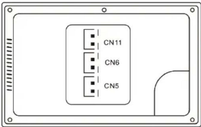
natural_image
Line drawing of a rectangular electronic device with a central display and control buttons (no text or symbols)Kültéri egység
natural_image
Close-up of a white electronic device with a blue circular component and a black remote control (no visible text or symbols)Főképernyő
- lépés: A hozzáadása
- lépés:
- lépés:
- lépés:
- lépés:
A MONITOR ÉS A KÜLTÉRI EGYSÉGEK TELEPÍTÉSE
natural_image
Exterior view of a modern office building (no signage)natural_image
Diagram of a device with two panels, one showing a green dashed line and the other a black outline, connected by a vertical tool (no text or symbols present)AZ AP2 KÜLTÉRI EGYSÉG CSATLAKOZTATÁSA
natural_image
Exterior view of a modern office building (no signage)BERENDEZÉSEK KARBANTARTÁSA
EVOLVE®
natural_image
Simple line drawing of a rectangular frame with a horizontal base and a small dot at the bottom (no text or symbols)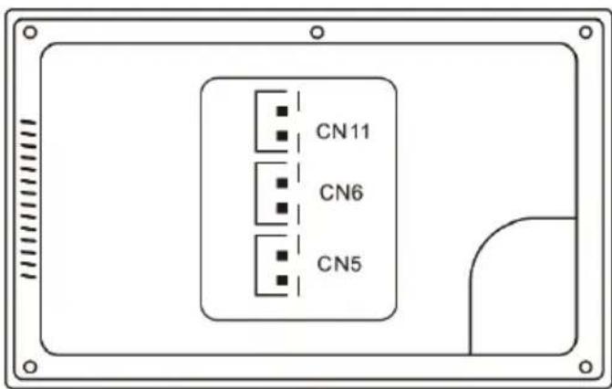
CN11: Conectare la sursa de alimentare de 18 V DC.
natural_image
Line drawing of a rectangular electronic device with a central screen and control buttons (no text or symbols)Unitate exterioară
INFORMATII DESPRE PRODUS
natural_image
Close-up of a remote control panel with a keypad and keychain, next to a black-and-white photo of a CD or DVD device (no visible text or symbols)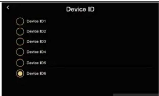
ADĂUGAREA ȘI CONECTAREA UNEI APLICATII SMART LIFE
Pasul 5: Adăugarea
Pasul 3:
Pasul 4:
Pasul 5:
Pasul 6:
INSTALAREA MONITORULUI ŞI A UNITĂȚILOR EXTERIOARE
natural_image
Exterior view of a modern office building (no signage)natural_image
Diagram of a device with two panels, one showing a green dashed line and the other a black outline, connected by a vertical line (no text or symbols present)FIXAREA UNITĂȚII EXTERIOARE AP2
natural_image
Exterior view of a modern office building (no signage)ÎNTRETINEREA ECHIPAMENTELOR
Copyright © Abacus Electric, s.r.o.
www.evolveo.com
| Power Adaptor Specifications | |
| Manufacturer's name or trade mark, commercial registration number and address | Shenzhen Mingxin power technologies |
| Model identifier | MX20Z-1801000 |
| Input voltage | AC100-240 |
| Input AC frequency | 50-60HZ |
| Output voltage | DC18-19 |
| Output current | 1.0-1.3 |
| Output power | 21-21.5 |
| Average active efficiency | 86,5% |
| Efficiency at low load (10 %) | 76,6% |
| No-load power consumption | 0.04-0.09W |
- Obsah / Content / Tartalom / Cuprins / Inhalt / Contenuto / Vsebina
- Obsah
- ZÁKLADNÍ FUNKCE A MOŽNOSTI SYSTÉMU
- Hlavní obrazovka
- MONTÁŽ MONITORU A VENKOVNÍCH JEDNOTEK
- PŘIPEVNĚNÍ VENKOVNÍ JEDNOTKY AP2
- ÚDRŽBA ZAŘÍZENÍ
- ZÁKLADNÉ FUNKCIE A MOŽNOSTI SYSTÉMU
- INFORMÁCIE O PRODUKTE
- SCHÉMA ZAPOJENIA 2 MONITOROV - FUNKCIA INTERKOMU
- Hlavná obrazovka
- INŠTALÁCIA MONITORA A VONKAJŠÍCH JEDNOTIEK
- PRIPEVNENIE VONKAJŠEJ JEDNOTKY AP2
- ÚDRŽBA ZARIADENÍ
- BASIC FUNCTIONS AND OPTIONS OF THE SYSTEM
- PACKAGING
- TECHNICAL SPECIFICATIONS
- Indoor unit
- Outdoor unit
- Indoor Wifi monitor
- PRODUCT INFORMATION EVOLVEO DOORPHONE AP1
- Detailed connection With the lock diagram
- Remark: 18V1A adapter as power supply:
- PRODUCT INFORMATION EVOLVEO DOORPHONE AP2
- View of the outdoor station
- NO 2. COM 3. NC 4. GND
- PRODUCT INFORMATION
- CONNECTION DIAGRAM OF 2 MONITORS - INTERCOM FUNCTION
- Remark: 18V1A adapter as central power supply:
- RFID CARD READER - SETTINGS
- Steps for setting up access control to the outdoor station:
- Setting up cards in zone 1
- Setting up cards in zone 2
- Setting up the Administrator card and adding cards using the Administrator card
- Delete all cards
- Change the default password
- K1 button settings
- OPERATING INSTRUCTIONS
- Main screen
- INTERKOM
- MONITOR INTERFACE
- SETTINGS
- OTHER SETTINGS
- STEPS TO CONTROL THE VIDEOPHONE AND INTERCOM IN THE APP
- ADDING AND CONNECTING A SMART LIFE APP
- INSTALLATION OF MONITOR AND OUTDOOR UNITS
- Attaching the monitor to the bracket.
- ATTACHING THE OUTDOOR UNIT AP1
- ATTACHING THE OUTDOOR UNIT AP2
- EQUIPMENT MAINTENANCE
- SAFETY NOTICE
- FIXING THE MOST COMMON PROBLEMS
- Monitor unresponsive/black screen
- Device does not have clear picture/sound, does not ring
- The lens is dewing
- Spontaneous ringing
- Whistling (feedback)
- It doesn't open the lock
- Sudden drop in microphone sensitivity
- DECLARATION OF CONFORMITY
- Importer / Manufacturer
- Tartalom
- Beltéri Wifi monitor
- Főképernyő
- A MONITOR ÉS A KÜLTÉRI EGYSÉGEK TELEPÍTÉSE
- AZ AP2 KÜLTÉRI EGYSÉG CSATLAKOZTATÁSA
- BERENDEZÉSEK KARBANTARTÁSA
- INFORMATII DESPRE PRODUS
- ADĂUGAREA ȘI CONECTAREA UNEI APLICATII SMART LIFE
- INSTALAREA MONITORULUI ŞI A UNITĂȚILOR EXTERIOARE
- FIXAREA UNITĂȚII EXTERIOARE AP2
- ÎNTRETINEREA ECHIPAMENTELOR
Brand : Evolveo
Model : DoorPhone AP1
Category : Intercom