
EV11 - Car charger PCE - Free user manual and instructions
Find the device manual for free EV11 PCE in PDF.


| Product Type | Wallbox EV11 (Car Charger) |
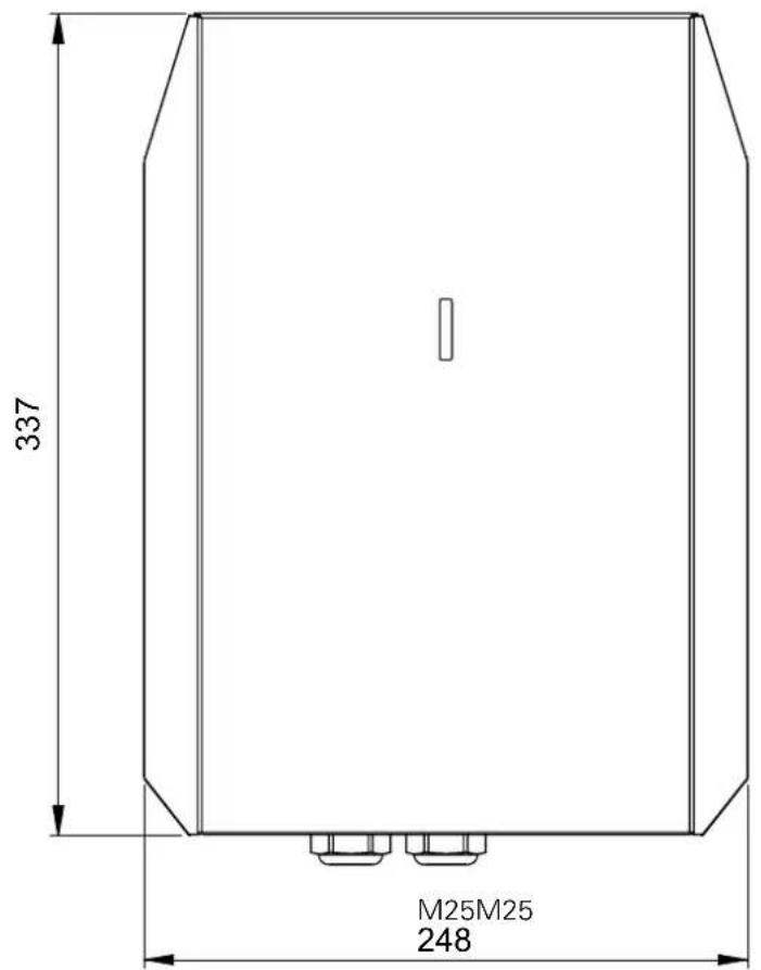
| Dimensions (W×H×D) | 248 × 337 × 124 mm |
| Weight | 4.65 kg |
| Charging Power | 3.7 kW (1-phase) or 11 kW (3-phase) |
| Rated Current | 16 A |
| Rated Voltage | 230 V / 400 V AC |
| Frequency | 50 Hz |
| Charging Cable | 5 m, Type 2 connector |
| Cable Cross Section | 5G2.5 mm² + 2×0.5 mm² |
| Number of Charging Points | 1 |
| Protection Rating | IP44 |
| Impact Resistance | IK08 |
| Ambient Temperature (Operation) | -25 °C to +40 °C |
| Ambient Temperature (Storage) | -35 °C to +55 °C |
| Housing Material | PC/ABS plastic, steel powder-coated cover |
| Mounting Type | Surface mounting (vertical) |
| Standards | IEC TS 61439-7, EN 61851-1 |
| External Protection | RCD Type A IΔN≤30 mA, MCB B16 or C16 |
| DC Fault Detection | 6 mA RCM module |
| LED Indicator | Flashing green (ready), solid green (vehicle detected), blue (charging), red (error) |
| Intended Use | Charging electric vehicles (PEV/PHEV) |
| Cleaning | Dry cloth only; no water jets or aggressive agents |
| Maintenance | Annual inspection by qualified electrician |
| Warranty | Modifications void warranty; original spare parts required |
Frequently Asked Questions - EV11 PCE
User questions about EV11 PCE
0 question about this device. Answer the ones you know or ask your own.
Ask a new question about this device
Download the instructions for your Car charger in PDF format for free! Find your manual EV11 - PCE and take your electronic device back in hand. On this page are published all the documents necessary for the use of your device. EV11 by PCE.
USER MANUAL EV11 PCE
Connection to the future
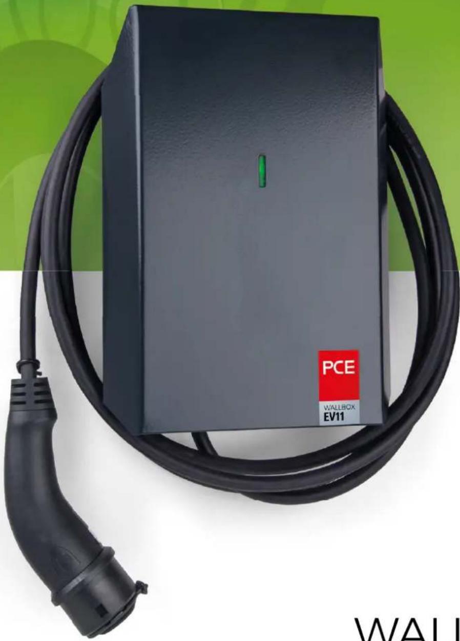
natural_image
Exterior view of a black electric vehicle charging station with a red 'PCE' and 'EV11' label (no additional text or symbols)Mounting and operating manual
WALLBOX EV11 page 22 - 39
Vehicle socket locked while charging. Charging must be terminated before charge plug can be removed.
Typenetikett

natural_image
White electrical outlet device with black cable, no visible text or symbols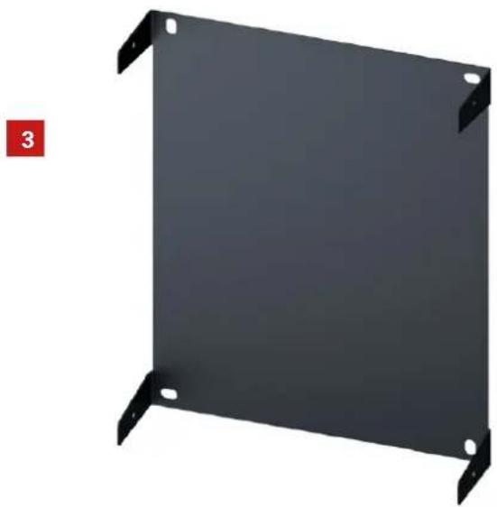
natural_image
Black metal panel with four corner mounting holes, no text or symbols visible2

natural_image
3D rendering of a dark gray industrial or electronic device casing with a white indicator light and red label (PCE, WAT-DCM, EV11) on the side.4

5

4. Maßskizzen
DE
E


natural_image
Technical line drawing of a mechanical component with dimension标注 (no text or symbols)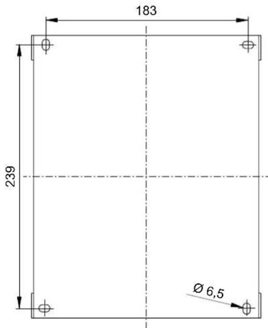
natural_image
Diagram showing a hand holding a pen next to a black panel with red arrows indicating direction (no text or symbols present)natural_image
Interior view of an open electrical enclosure with internal components and wiring (no text or symbols visible)natural_image
White industrial enclosure with metal mounting feet and a central circular component, labeled '100 Ncm' (no other text or symbols visible)
natural_image
Close-up of an electrical control panel with multiple colored wires and terminal blocks (no readable text or symbols)natural_image
Electrical wiring and terminal block with labeled components (L1, L2, L3, N, PE) and color-coded wires (no readable text or symbols)natural_image
Exterior view of an electric vehicle charging plug connected to a digital multimeter (no visible text or symbols on the device body)7. Bedienung
1.1 Use of operating manual 23
1.2 Target group 23
1.3 Customer responsibility....23
1.4 Liability limitation....23
1.5 Types of safety instructions....24
1.6 Safety instructions....24
1.7 Intended use 25
1.8 Reasonably foreseeable misuse....25
1.9 Warranty....25
2. Description of the charging station 26
3. Scope of delivery 27
4. Dimensional drawings ...... 28
5. Technical data 29
6. Mounting....30
6.1 Site selection....30
6.2 Mounting position 30
6.3 Surface mounting 31
6.4 Conditions for the electrical connection 33
6.5 Electrical connection of the charging station....34
6.6 Safety checks 35
6.7 Start-up....35
7. Handling 36
7.1 Meaning of the LED status display 36
7.2 Vehicle charging 36
7.3 Ending the charging process 37
8. Troubleshooting....38
9. Cleaning and maintenance....39
9.1 Cleaning....39
9.2 Inspection and maintenance 39
9.3 Spare parts 39
9.4 Contact and support....39
9.5 Disposal....39
Document: 11202 EV11 BA V1.1 07/2021
© PC Electric Gesellschaft m.b.H.
This document is protected by copyright.
The content of this document is property of PC Electric Gesellschaft m.b.H. and may not be copied or reproduced in whole or in part.
We reserve the right to make changes in the interest of technical development.
No responsibility is taken for the correctness of this information.
1. General information
1.1 Use of operating manual
This operating manual contains necessary information for the proper installation and operation of the WALLBOX EV11 in all life cycle phases. The safety-related information ensures the safe and efficient handling of the WALLBOX EV11 for people and the environment. The operating instructions are an integral part of the product. It must be kept for the entire service life of the product and must be carefully read and understood by the owner and all skilled personnel before starting any work.
The illustrations are for better understanding and may differ from the delivered version.
1.2 Target group
This operating manual is intended for electrical engineering specialists who install and commission the WALLBOX EV11 and for all persons who operate the product.
1.3 Customer responsibility
The following information must be observed by the customer:
Provide the required documents for qualified electricians.
Ensure that the device is used for its intended purpose.
1.4 Liability limitation
PC Electric GmbH does not accept any liability for damage caused by:
Disregard of these operating instructions
Use not in accordance with the intended purpose
Use of unqualifi ed personnel
Use of untested components from third party suppliers
1.5 Types of safety instructions
You will find notes and warnings of possible dangers at various points in the manual.
The symbols used have the following meaning:

DANGER
Failure to observe will result in death or serious injury.

WARNING
Non-compliance can lead to death or serious injury.
Escape from the danger.

CAUTION
Failure to observe this warning may result in injury. Escape from danger.

NOTE
Explanation Note
Important supplementary information for the PCE Wallbox EV11.
1.6 Safety instructions

CAUTION
Possible property damage!
Pull the charging cable out of the holder only by the handle and not by the cable.
The charging cable must not be mechanically damaged (bent, pinched or run over).
The contact area of the vehicle coupling must not come into contact with heat sources, dirt or water. Use protective cap when not in use.

WARNING
Danger due to electric shock and fi re hazard!
Assembly, installation, initial start-up, maintenance, retrofiting or disposal of the charging station must be carried out by relevantly trained, qualified and authorized electricians
1). The country-specific directives, safety regulations and applicable product standards must be observed.
The charging station may only be operated in perfect condition.
A damaged charging station must be taken out of service immediately and repaired or replaced by a qualified and authorized electrician.
No markings (e.g. safety symbols, warning notices, line markings...) may be removed from the charging station.
Observe the notes and instructions for your vehicle before charging the vehicle with the charging station.
1.7 Intended use
The charging station is intended for charging electrically powered vehicles, e.g. electric vehicles (PEV) or plug-in hybrid vehicles (PHEV).
The intended use of the charging station includes compliance with the environmental conditions for which this charging station was developed (see page 30 / chapter 6 mounting).
The charging station was developed, manufactured, tested and documented in compliance with the relevant standards. If the instructions and safety information described for the intended use are observed, the product does not normally pose any risk to the health of persons or damage to property.
The respective national regulations must be observed for mounting and connecting the charging station.

WARNING
Failure to observe the safety instructions may result in danger to life, injury and damage to the charging station!
The intended use must be observed.
All specifications for mounting the charging station must be observed (see chapter „Mounting“)
Work on the charging station may only be performed by qualified electricians.
Use personal protective equipment.
The operating conditions in the technical data must be observed.

NOTE
Any use beyond this is considered improper. PC Electric GmbH accepts no liability for any resulting damage to people, the environment or possible damage to property.
1.8 Reasonably foreseeable misuse
If used outside the specified limits or handled in a manner not described in this operating manual, the safety and properties of the product may be impaired.
No unauthorized conversions or modifications may be made to the charging station.
Improper use (e.g.: pulling the vehicle coupling by the cable, falling from a great height, throwing, etc.) is not permitted.
Do not use defective, worn or dirty charging couplers.
The use of adapters of any kind is prohibited.
Connection of other devices (e.g. power tools) is not permitted.
The charging station must not be covered with other objects or materials.
No foreign objects may be placed on the charging station.
1.9 Warranty
Only maintenance work expressly permitted by PC Electric GmbH may be carried out.
Modifi cations and alterations lead to the loss of the warranty claim.

NOTE
Further information (e.g. chemical resistance or UV resistance of the charging station) can be found in the PCE product catalog. (www.pcelectric.at).
2. Description of the charging station
Plastic housing: impact resistant PC/ABS
Housing cover and mounting plate: sheet steel, powder-coated RAL7016

sticker
LED indicator status



ACHTUNG!
Vehicle socket locked while charging. Charging must be terminated before charge plug can be removed.
Type label

3. Scope of delivery
| Menge | ||
| 1 | PCE wallbox with fi x mounted charging cable and vehicle coupling type 2 | 1 |
| 2 | Housing cover 1 | |
| 3 | Mounting plate 1 | |
| 4 | Pan head screw DIN 7981 4,8x9,5 VZ 4 | |
| 5 | Mounting- and operating manual 1 | |
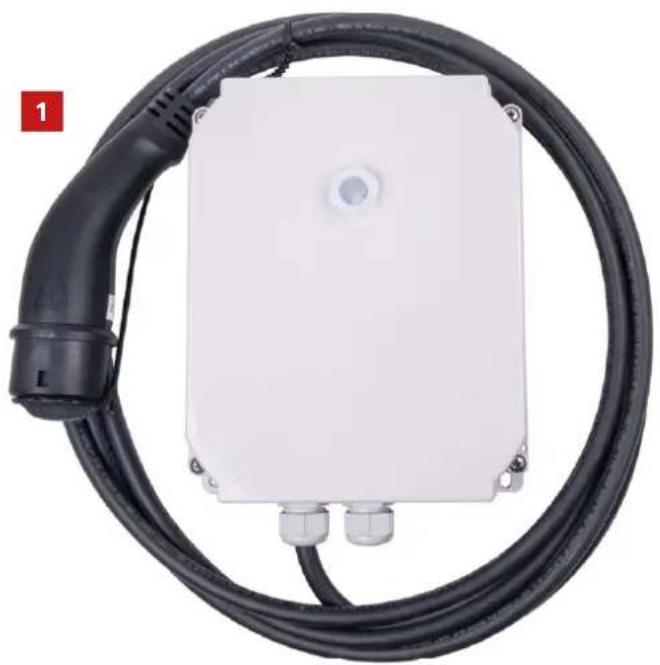
natural_image
White electrical connector with black cable, no visible text or symbols
natural_image
Black metal panel with four corner mounting holes, no text or symbols visible2

natural_image
3D rendering of a dark gray industrial or electronic device casing with a white vertical slot and red label (PCE, WALDOE EV11) on the side (no readable text beyond labels)4

5

4. Dimensional drawings
DE
EN

natural_image
Technical line drawing of a mechanical component with dimension标注 (no text or symbols)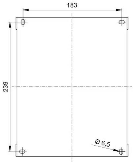
drilling dimensions mounting plate
5. Technical data
| Product type | Wallbox EV11 |
| Conformity of standards IEC TS 61439-7; EN 61851-1 | |
| Number of charging points 1 | |
| Charging cable length / cross section 5m / 5G2,5mm2 + 2x0,5mm2 | |
| Vehicle coupling Type 2 | |
| Charging power 3,7 kW (1~) or 11kW (3~) | |
| Charging mode Mode 3, Case C (with vehicle coupling) | |
| Type of charging current AC 3-phase (or AC 1-phase) | |
| Number of contacts 5 (L1, L2, L3, N, PE) | |
| Rated current InA | 16A |
| Cross section (supply) 5G2,5mm2 (16A 3~), 3G2,5mm2 (16A 1~) | |
| Cable gland (supply) M25 (cable diameter 8–17mm) | |
| Rated voltage UN | 230V / 400V |
| Rated frequency fN | 50 Hz |
| Mains system supply TN/TT | |
| Protection class II | |
| Overvoltage category III | |
| EMV class | B |
| Ambient temperature operation | -25°C to +40°C (without direct sunlight) |
| Ambient temperature storage | -35°C to +55°C |
| Protection rating | IP44 |
| Impact resistance | IK08 |
| External fuse protection required | RCD Typ A IΔN≤30mA |
| Circuit breaker | not integrated (MCB B16 or C16 necessary) |
| Status according to EN 61851-1 | Status D with fans is not supported |
| DC fault current detection | 6mA RCM Modul |
| Housing | Plastic housing made of PC/ABS (similar to RAL7035), Housing cover steel powder coated (similar to RAL7016) |
| Dimensions/weight | WxHxD 248 x 337 x 124mm / 4,65 kg |
| Mounting type | Surface mounting |
The following directives and standards have been applied:
Low Voltage Directive 2014/35/EU
EMC Directive 2014/30/EU
ROHS Directive 2011/65/EU
IEC TS 61439-7; EN 61851-1
CE

6. Mounting
6.1 Site selection
The charging station is suitable for indoor and outdoor use.
Environmental conditions:
- No direct sunlight
- Ambient temperature: -25 °C to +40 °C
- Humidity: 5% to 95%
- Altitude: 0 m to 2000 m

Never mount the charging station in such a way that it is exposed to direct sunlight.

Do not mount the charging station near fl ammable or explosive substances.

The charging station must not be mounted in locations where it is exposed to direct jets of water (e.g. high-pressure cleaners or car washes).

Do not install the charging station in areas subject to flooding.

The charging station must not be mounted in places where it blocks escape routes or people passages.
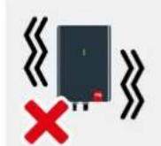
Only mount the charging station in a vibration-free environment.
6.2 Mounting position

The charging station must be mounted vertically on a vertical, level wall or on a suitable pedestal.

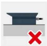


i NOTE
The lowest point of the vehicle coupling in the rest position must be between 0.5 m and 1.5 m above ground level.
6.3 Surface mounting

NOTE
Check the charging station for any damage after unpacking.

NOTE
For assembly and installation of the charging station, the respective national regulations must be observed.

NOTE
Suitable tools must be used for assembly.
Place the mounting plate on the wall as a template.
Use a level to ensure that the wallbox is leveled.
Mark out the drill holes.

natural_image
Diagram showing a hand holding a pen and red arrows pointing to a panel with mounting holes (no text or symbols)Drill at the marked points using a drill bit suitable for the wall material.

NOTE
When mounting, make sure that the mounting plate and the underside of the housing are not distorted or deformed.
Place the mounting plate behind the housing together with the lower part of the PCE Wallbox EV11 and fi x both with 4 pan-head screws suitable for the wall condition. The max. torque of 120 Ncm must not be exceeded.

natural_image
Cross-sectional diagram of an electrical enclosure with internal components and wiring (no text or symbols)For initial startup, follow the „Electrical connection" instructions (page 34 / chapter 6.5)

Mounting
Fasten the housing cover using the four screws supplied (Fig.1). The max. torque of 100 Ncm for the housing screws must not be exceeded.
To mount the housing cover, hold it towards the mounting plate as shown in Fig. 2 (to do this, slightly pull the wings of the cover apart) and first fasten the cover at the bottom using the supplied pan-head screws.

natural_image
White industrial enclosure with metal mounting feet and a central bolt, shown with red dashed lines indicating measurement (no text or symbols on the device itself)
Swivel up the housing cover (Fig. 3) and fasten the cover also at the top with the supplied pan-head screws.

6.4 Conditions for the electrical connection
Specifications for the sub-distribution:
Each charging point must have its own supply line with appropriate fuse protection.
The wallbox needs a suitable line circuit breaker and residual current circuit breaker.
Since the wallbox already has a DC fault detection >6mA, you do not need a RCD type B.
If possible, use overvoltage protection in the subdistribution.
Observe the labeling of the connection terminals (L3, L2, L1, N, PE).
Use the cable cross-sections specified in the table.
5 SAFETY RULES:
Before starting to work:
- Disconnect
- Secure against restarting
- Check that no voltage is present
• Ground and short-circuit
• Cover or short-circuit surrounding parts that are under voltage or fence off


NOTE
The charging station does not have its own mains switch. The circuit breaker of the supply line serves as the mains disconnection device.
| Terminals used: | |
| Manufacturer: | Weidmüller Interface GmbH & Co KG |
| Make: | Klippon®Connect |
| Product Family: | A-Series |
| Type: A4C 2.5 | |
| Rated data | |
| Rated cross section: | 2,5 mm2 |
| Rated voltage: | 800 V |
| Rated impulse withstand voltage: | 8 kV |
| Rated current: | 24 A |
| Power dissipation: | 0,77 W |
| Standards: | IEC 60947-7-1 |
| Current at max. conductor: | 24 A |
| Clampable conductors (rated connection) | |
| Conductor cross-section AWG min. AWG 12 / max. AWG 28 | |
| Conductor cross-section, solid min. 0,5mm2 / max. 2,5 mm2 | |
| Conductor cross-section, fl exible with end sleeves | |
| with plastic collar DIN 46228/4 min. 0,5mm2 / max. 2,5 mm2 | |
| Material Wemid | |
| Color dark beige | |
| Flammability class according to UL94 V-0 | |
| Continuous service temperature | min.-60°C / max. 130°C |
6.5 Electrical connection of the charging station
For the electrical connection of the charging station, proceed as follows:
The supply line (supply) is fed through a cable gland (M25) from below. Insert the supply line and connect it to the screwless terminal block (Klippon- ^® Connect) of the charging station (see picture). Use wire end sleeves (according to manufacturer's instructions) for fl exible conductors.
Tighten cable gland
Check the sealing gap for possible foreign objects and place the plastic cover on the plastic housing.
Fasten the plastic cover using the four metric screws (max. 100 Ncm).


natural_image
Close-up of an electrical control panel with multiple colored wires and labeled terminals (no readable text beyond labels)3-phase supply
(L3, L2, L1, N, PE)

single phase supply
(L1, N, PE)
6.6 Safety checks
Electrical systems or devices must be tested for the effectiveness of the protective measure(s) of the system, in accordance with the nationally applicable regulations, by the installer of the system or device before initial commissioning. This also applies to the expansion or modification of existing systems or electrical devices. All regulations for protective measures must be observed.
The following points must be taken into consideration:
The tests (continuity of the connections of the protective conductor; insulation resistance; RCD (FI) tripping current, tripping time, ...) must be carried out.
The measuring devices used must comply with the national regulations!
The measurement results must be documented. A test protocol of the test must be created and kept.
6.7 Start-up
Apply voltage to the charging station (e.g. switch on circuit breaker).
The LED status display should now fl ash green.
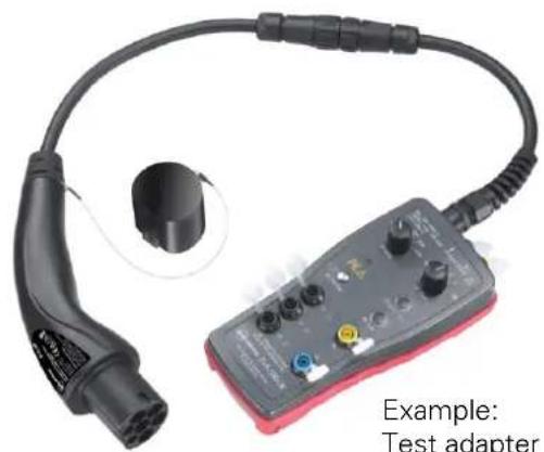
Check the individual functions and statuses using a suitable test adapter and
Measure the correct voltages at L1, L2, L3, N and PE according to the instructions of the test adapter manufacturer.

CAUTION
Do not remove the metal housing cover or the plastic housing cover as soon as the charging station is under voltage.
natural_image
Electric vehicle charging plug connected to a test adapter device (no visible text or symbols on the device body)7. Handling
7.1 Meaning of the LED status display
The charging station has an LED status display that indicates the actual status of the charging station. The colors of the LED status display represent the following states:

LED fl ashes GREEN
The charging station is ready for use

LED illuminates GREEN
Vehicle detected

LED illuminates BLUE
Vehicle charging

LED illuminates or fl ashes RED
Error

CAUTION
Avoid direct eye contact with the illuminated LED.
7.2 Vehicle charging
Your charging station has a permanently attached charging cable.

CAUTION
Make sure that the charging cable is not under tension at any time.
Make sure that the charging cable, when connected to the charging station and the vehicle, does not block any paths of other road users!
Risk of tripping due to charging cable lying on the floor.
Make sure that the LED status indicator pulses green.
Connect the charging cable to the electric vehicle. An automatic locking of the charging coupling takes place. The LED status indicator lights up blue.

NOTE
The charging station must not be covered with other objects or materials.
No foreign objects may be placed on the charging station.
7.3 Ending the charging process
When the desired state of charge is reached, end the charging process on your electric vehicle.

NOTE
After the vehicle is fully charged, the vehicle will end the charging process automatically. LED illuminates GREEN.
Disconnect the charging cable from the electric vehicle. To do this, follow the instructions in the user manual for your vehicle.

NOTE
Do not disconnect the charging cable from the charging station until the automatic lock is released.
8. Troubleshooting
Error description LED Status Possible cause / remedy
| The charging process is not started.The status LED fl ashes green. |  | Vehicle is not detectedFirst check the fi t of the charging cable on the vehicle.If the problem persists, check if the vehicle displays an error message. In this case, contact your vehicle dealer for more information.Charging cable defectContact our support. |
| The status LED lights up red |  | DC error or general errorRemove the charging cable. If the status LED is still red, contact our support team |
| The status LED does not light up. | [ETOW] | The charging station is not supplied with voltage.Contact the installer of your charging station.The status LED is defect.Contact our support. |

NOTE
Please note that you as the user may only perform the troubleshooting measures listed in the table yourself. All other troubleshooting measures may only be performed by a qualified technician.
9. Cleaning and maintenance
9.1 Cleaning

CAUTION
Stop the charging process before cleaning, care and maintenance work. In addition, disconnect the charging cable from any connected vehicle and place the protective cap on the charging coupler.
You can clean the charging station as follows: Wipe the outside of the charging station with a dry cloth.

CAUTION
The charging station must not be cleaned with a water or steam jet cleaner.

CAUTION
Never use aggressive cleaning agents, abrasive materials or jet water to clean the charging station. This may result in damage to the charging station.
9.2 Inspection and maintenance
The charging station is basically maintenance-free, but must be checked regularly by the owner for defects in the charging socket or charging coupling (including charging cable) and for damage to the housing (visual inspection) as well as for defects, wear and dirt on the charging socket or charging coupling including charging cable.
The charging station and the associated sub-distribution must be checked once a year for function and safety by a qualified electrician as part of the periodic inspection. The result of the inspection must be recorded and kept until the next inspection.

NOTE
Inspection, maintenance or repair of the charging station may only be carried out by qualified electricians.
9.3 Spare parts
Only original spare parts are to be used.
9.4 Contact and support
PC Electric Gesellschaft m.b.H.
Diesseits 145
Dispose of the wallbox properly in accordance with the country-specific regulations.
Electrical and electronic equipment must be disposed of separately from general household waste.
The materials are recyclable according to their labeling.

PCE
Connection to the future

- Mounting and operating manual
- WALLBOX EV11 page 22 - 39
- Typenetikett
- Maßskizzen
- Bedienung
- Description of the charging station 26
- Scope of delivery 27
- Dimensional drawings ...... 28
- Technical data 29
- Mounting....30
- Handling 36
- Troubleshooting....38
- Cleaning and maintenance....39
- General information
- Use of operating manual
- Target group
- Customer responsibility
- Liability limitation
- Types of safety instructions
- DANGER
- WARNING
- CAUTION
- NOTE
- Explanation Note
- Safety instructions
- Possible property damage!
- Danger due to electric shock and fi re hazard!
- Intended use
- Failure to observe the safety instructions may result in danger to life, injury and damage to the charging station!
- Reasonably foreseeable misuse
- Warranty
- Description of the charging station
- ACHTUNG!
- Scope of delivery
- Dimensional drawings
- Technical data
- Mounting
- Site selection
- Environmental conditions:
- Mounting position
- i NOTE
- Surface mounting
- Mounting
- Conditions for the electrical connection
- Specifications for the sub-distribution:
- SAFETY RULES:
- Electrical connection of the charging station
- Safety checks
- Start-up
- Handling
- Meaning of the LED status display
- LED fl ashes GREEN
- LED illuminates GREEN
- LED illuminates BLUE
- LED illuminates or fl ashes RED
- Vehicle charging
- Ending the charging process
- Troubleshooting
- Cleaning and maintenance
- Cleaning
- Inspection and maintenance
- Spare parts
- Contact and support
- PCE
- Connection to the future
Brand : PCE
Model : EV11
Category : Car charger