MRP-201 - Meter Sonel - Free user manual and instructions
Find the device manual for free MRP-201 Sonel in PDF.


| Product Type | RCD Tester (Residual Current Device Tester) |
| Brand | Sonel |
| Model | MRP-201 |
| Dimensions | 220 x 98 x 58 mm |
| Weight | Approx. 0.7 kg |
| Power Supply | 4 x AA alkaline or NiMH rechargeable batteries |
| Display | LCD segment display |
| Measurement Category | IV 300V / III 600V (EN 61010-1) |
| Ingress Protection | IP67 |
| Operating Temperature | -10°C to +50°C |
| Storage Temperature | -20°C to +70°C |
| Humidity | 20% to 90% RH |
| Altitude | < 2000 m |
| Memory Capacity | 990 cells, 10,000 entries (10 banks x 99 cells) |
| Data Transmission | Radio link, ISM 433 MHz (via optional OR-1 module) |
| Standards Compliance | IEC 61557, EN 61326-1, EN 61326-2-2, ISO 9001 |
| Main Functions | RCD disconnection time (tA), disconnection current (IA), contact voltage (UB), earth resistance (RE), voltage and frequency measurement, automatic RCD test (FULL/STANDARD) |
| Maintenance | Clean with soft damp cloth and mild detergent; no solvents |
| Safety Features | Double insulation, contact electrode for PE validation, overvoltage protection, temperature shutdown |
| Spare Parts / Repairability | Repairs only by authorized service center; accessories include OR-1 module and software |
| General Information | Modern, easy-to-use measuring device for checking protection against electric shock in mains systems |
Frequently Asked Questions - MRP-201 Sonel
User questions about MRP-201 Sonel
0 question about this device. Answer the ones you know or ask your own.
Ask a new question about this device
Download the instructions for your Meter in PDF format for free! Find your manual MRP-201 - Sonel and take your electronic device back in hand. On this page are published all the documents necessary for the use of your device. MRP-201 by Sonel.
USER MANUAL MRP-201 Sonel
natural_image
Line drawing of a handheld electronic device with control panel and buttons (no text or symbols)USER MANUAL
RCD TESTER
MRP-201
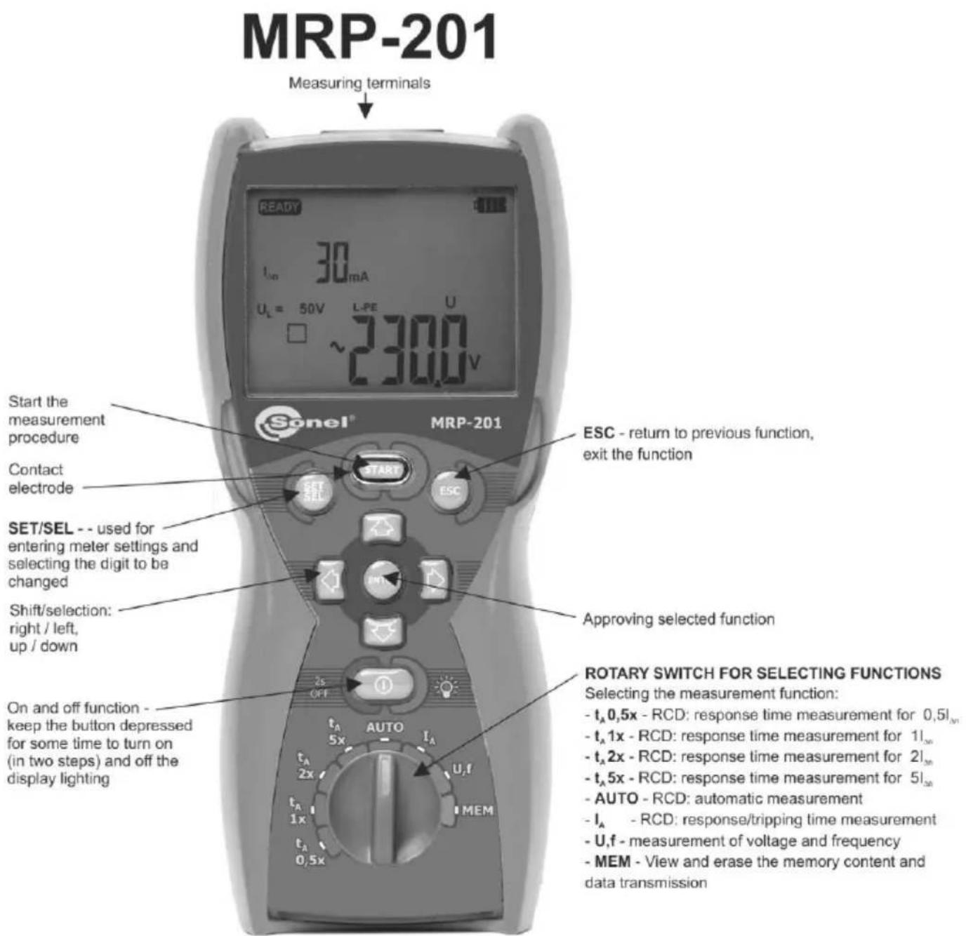
DISPLAY
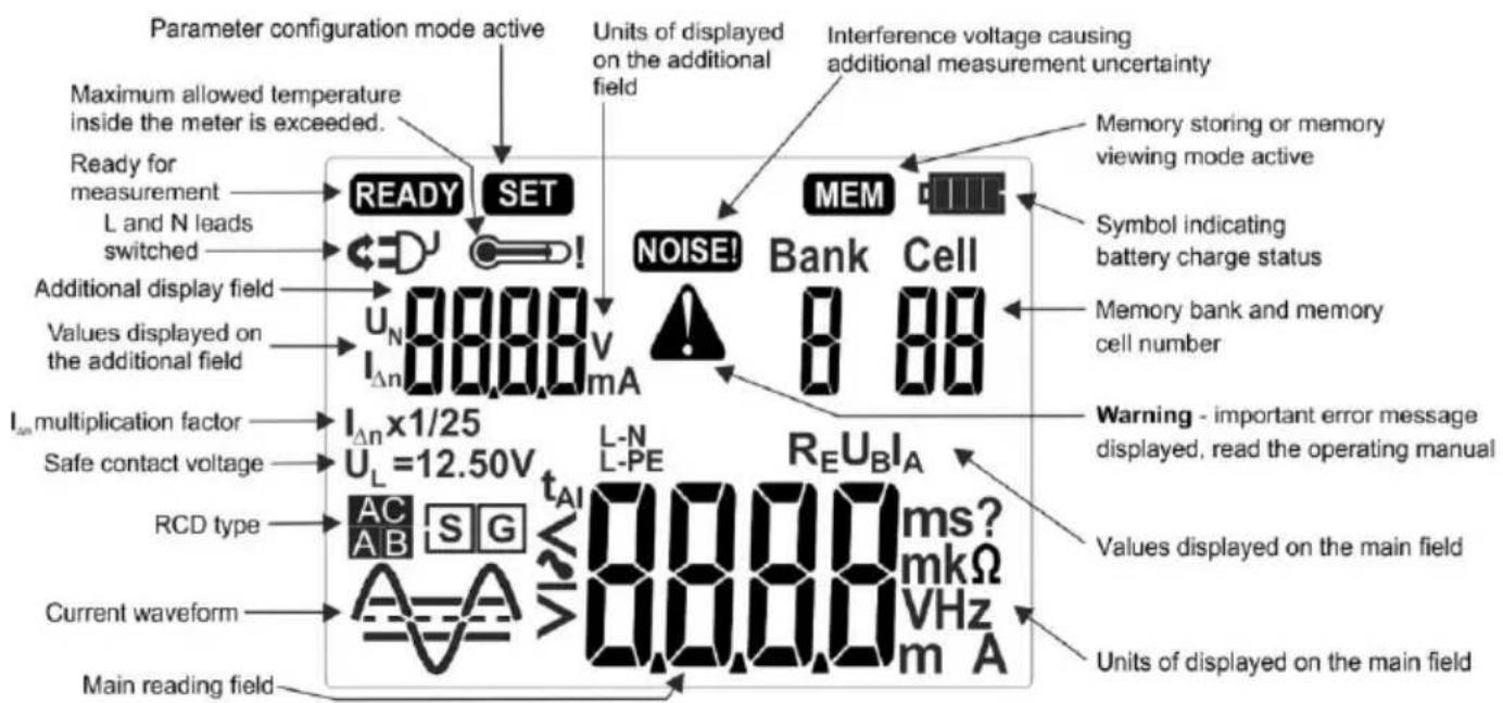
USER MANUAL
RCD TESTER MRP-201

SONEL S.A.
Wokulskiego 11
58-100 Świdnica
Poland
The MRP-201 meter is a modern, easy and safe measuring device. Please acquaint yourself with the present manual in order to avoid measuring errors and prevent possible problems related to operation of the meter.
CONTENTS
1 Safety 4
2 Measurements....5
2.1 Selection of general measurement parameters 5
2.2 Remembering the last measurement result 6
2.3 Measurement of alternating voltage....7
2.4 Measurement of voltage and frequency....7
2.5 Validation of the connections the protective conductor....7
2.6 Measurement of RCD parameters 8
2.6.1 Measurement of RCD disconnection current 8
2.6.2 Measurement of RCD disconnection time 11
2.6.3 Automatic measurement of RCD parameters....13
3 Memory of measurement results....21
3.1 Storing the measurement result data in the memory 21
3.2 Changing the cell and bank number 23
3.3 Viewing memory data.... 24
3.4 Deleting memory data 24
3.4.1 Deleting bank data....24
3.4.2 Deleting the whole memory....25
3.5 Communication with PC....26
3.5.1 Computer connection accessories 26
3.5.2 Data transmission....26
4 Troubleshooting....28
5 Meter power supply 30
5.1 Monitoring of the power supply voltage.... 30
5.2 Replacing batteries (rechargeable batteries) 30
5.3 General principles regarding using Ni-MH accumulators.... 32
6 Cleaning and maintenance 33
7 Storage....33
8 Dismantling and utilisation....33
9 Technical specifications ....34
9.1 Basic data 34
9.2 Other technical specifications 36
9.3 Additional data according to IEC 61557-6 (RCD) 37
10 Manufacturer ....37
1 Safety
MRP-201 meter is designed for performing check tests of protection against electric shock in mains systems. The meter is used for making the measurements the results of which determine safety of electrical installations. Therefore, in order to provide conditions for correct operation and the correctness of the obtained results, the following recommendations must be observed:
- Before you proceed to operate the meter, acquaint yourself thoroughly with the present manual and observe the safety regulations and specifications determined by the producer.
- Any application that differs from those specified in the present manual may result in a damage to the device and constitute a source of danger for the user.
- The device must be operated solely by appropriately qualified personnel with relevant certificates to realise measurements of electric installation. Operation of the meter realised by unauthorised personnel may result in damage to the device and constitute a source of danger for the user.
- Using this manual does not exclude the need to comply with occupational health and safety regulations and with other relevant fire regulations required during the performance of a particular type of work. Before starting the work with the device in special environments, e.g. potentially fire-risk/explosive environment, it is necessary to consult it with the person responsible for health and safety.
- It is unacceptable to operate the following:
A damaged meter which is completely or partially out of order,
A meter with damaged test leads insulation,
A meter stored for an excessive period of time in disadvantageous conditions (e.g. excessive humidity). If the meter has been transferred from a cool to a warm environment of a high level of relative humidity, do not realise measurements until the meter has been warmed up to the ambient temperature (approximately 30 minutes).
- It should be remembered that BAT message appearing on the display indicates that supply voltage of the meter is too low. This message signals also that the batteries must be replaced or the accumulator charged. Measurements performed by means of the meter whose supply voltage is too low are burdened with additional errors that are impossible to be estimated by the user. Such measurements must not be relied on in order to state correctness of protection of a network tested.
- Battery spill and damage to the meter may occur if discharged batteries are left in the meter.
- Before measurements may commence, make sure the test leads are connected to the appropriate measurement sockets.
- Do not operate a meter with an open or incorrectly closed battery (accumulator) compartment or power it from other sources than those specified in the present manual.
• Repairs may be realised solely by an authorised service point.
ATTENTION!
Only standard and additional accessories for a given device should be used. Use of different accessories can lead to errors in the test connection and can introduce additional measurement uncertainties.
Note:
An attempt to install drivers in 64-bit Windows 8 may result in displaying "Installation failed" message.
Cause: Windows 8 by default blocks drivers without a digital signature.
Solution: Disable the driver signature enforcement in Windows.
Attention:
Due to continuous development of the meter's software, the actual appearance of the display, in case of some of the functions, may slightly differ from the display presented in this operating manual.
2 Measurements
WARNING:
During RCD measurements, the earthed parts and parts accessible in the electrical installation being tested must not be touched.
WARNING:
During a measurement, switching of the range switch is forbidden because it may damage the meter and pose a threat to the user.
2.1 Selection of general measurement parameters
①
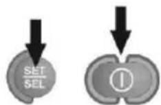
Keeping the SET/SEL button depressed, turn on the meter and wait for the parameter selection screen.
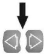
Use the , buttons to go to the next parameter.
Use the △ buttons to change the parameter value. The value or symbol to be changed is flashing. The symbol indicates an active parameter, the no symbol indicates an inactive one.
②
Set the parameters according to the following algorithm:
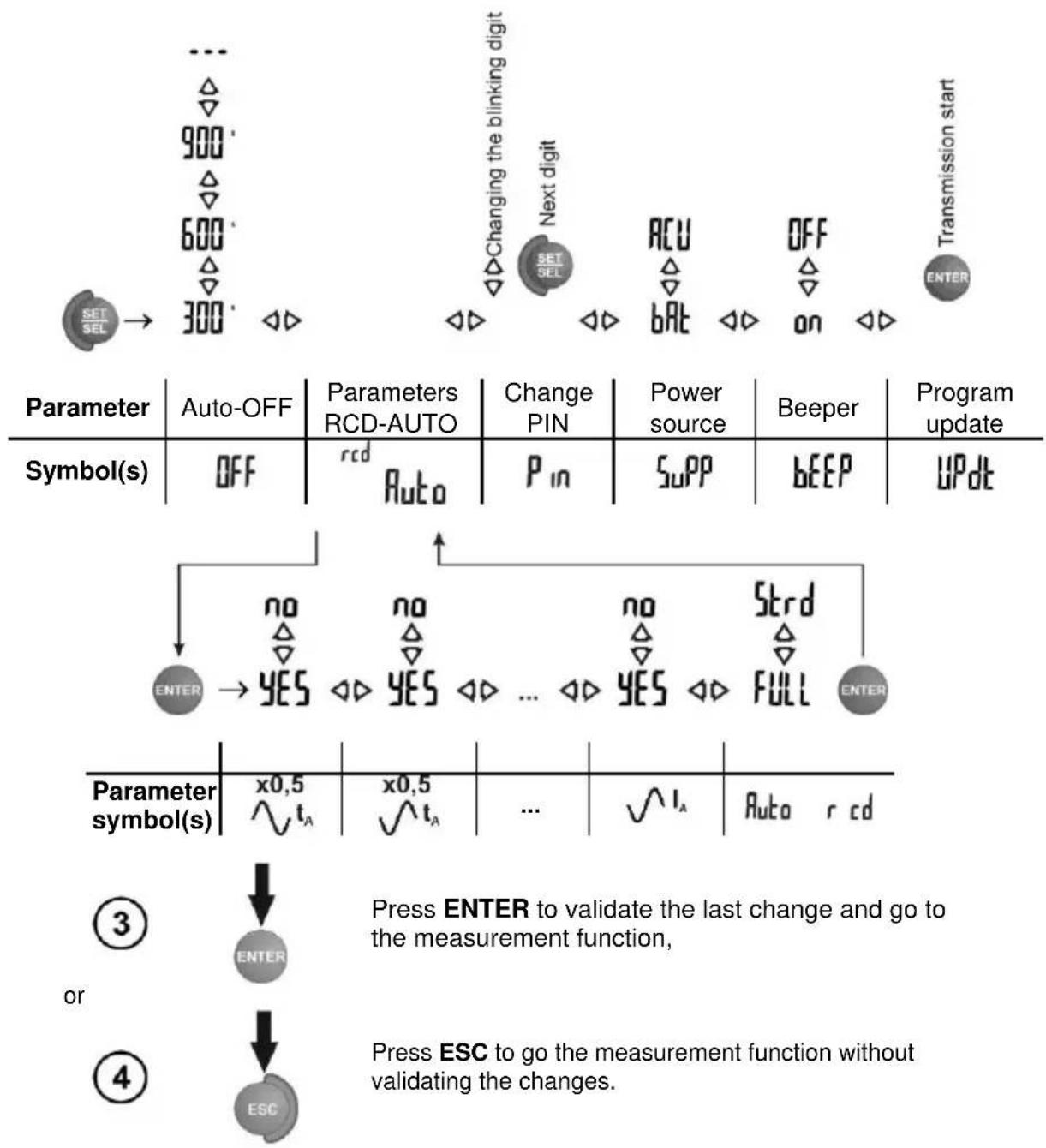
flowchart
graph TD
    A["SET SEL"] --> B["300"]
    C["900"] --> D["Changing the blinking digit"]
    E["600"] --> F["Next digit"]
    G["ACU"] --> H["BU"]
    I["OFF"] --> J["ON"]
    K["TRANSMISSION START"] --> L["ENTER"]

    M["Symbol(s)"] --> N["OFF"]
    N --> O["rcd Auto"]
    O --> P["P in"]
    P --> Q["SuPP"]
    Q --> R["bEEP"]
    S["Program update"] --> T["UPdt"]

    U["ENTER"] --> V["YES"]
    V --> W["NO"]
    W --> X["Strd"]
    X --> Y["FULL"]
    Y --> Z["ENTER"]

    AA["Parameter symbol(s)"] --> AB["x0,5 ∨ t_A"]
    AB --> AC["x0,5 ∨ t_A"]
    AC --> AD["..."]
    AD --> AE["√ I_A"]
    AE --> AF["Auto r cd"]

    AG["Press ENTER to validate the last change and go to the measurement function, or"] --> AH["ENTER"]
    AI["Press ESC to go the measurement function without validating the changes."]
Notes:
- Symbol in this case indicates positive phase/polarity, while symbol - negative. The same applies to pulsed and direct current.
- Symbol -indicates that no auto-off time has been set.
- RCD Auto mode settings are described in Section 2.6.3.
- PIN settings - see section 3.5.2 Data Transmission.
2.2 Remembering the last measurement result
The result of the latest measurement is remembered by the meter until a next measurement is started or measurement settings are changed or the measuring function is changed by means of the rotary switch or the meter is switched off. When you go to the output screen of a given function, you can recall this result with the ESC button by pressing ENTER. Similarly, you can view the latest measurement result after turning off and then turning on the meter (if the position of function selector has not been changed).
2.3 Measurement of alternating voltage
The meter measures and displays alternating mains voltage in all measuring functions. This voltage is measured for the frequencies within the range of 45..65 Hz. The test leads should be connected as for a given measuring function.
2.4 Measurement of voltage and frequency
①
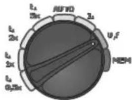
Set the rotary switch in the U,f position.
②
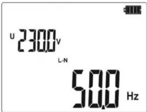
Read the result of measurement: the voltage on the secondary display field, the frequency of the principal.
2.5 Validation of the connections the protective conductor
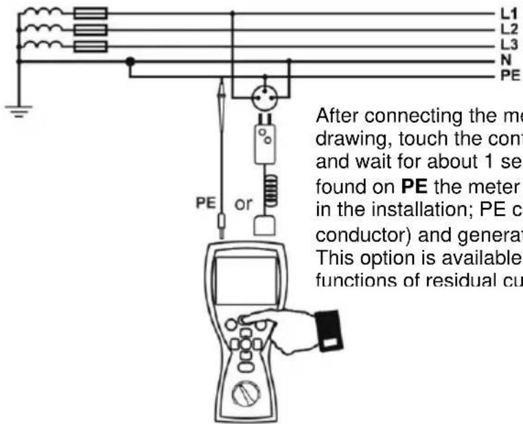
After connecting the meter according to the drawing, touch the contact electrode with a finger and wait for about 1 second. When voltage is found on PE the meter displays symbol PE (error in the installation; PE connected to the phase conductor) and generates a continuous beep. This option is available for all measuring functions of residual current devices (RCD).
Notes:
WARNING:
When a dangerous voltage is detected on PE conductor, measurements must be immediately stopped and a fault in the installation must be removed.
- The person making a measurement must ensure that he/she is standing on a non-insulated floor during the measurement; otherwise the result of the measurement may be incorrect.
- The threshold value, which triggers the signal of exceeded allowable voltage on PE conduit, is approximately 50 V.
2.6 Measurement of RCD parameters
2.6.1 Measurement of RCD disconnection current
①
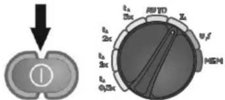
Turn on the meter. Turn the rotary switch to the position IA.
②
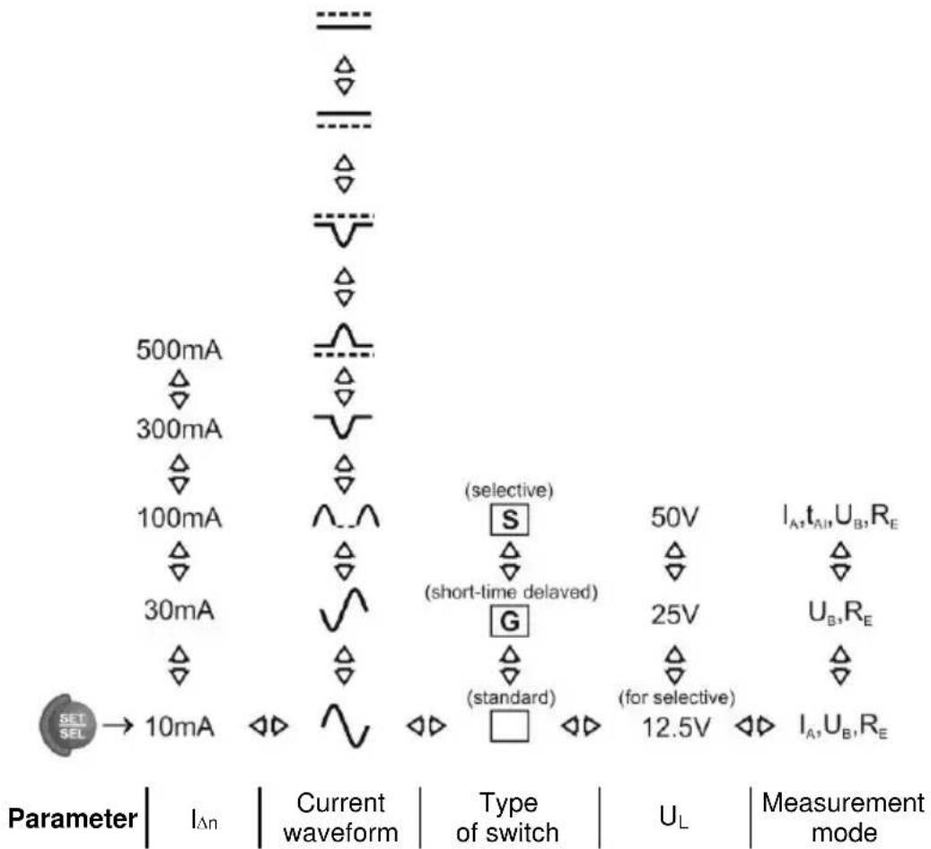
Set the parameters according to the following algorithm, and according to the rules described in general parameters setting.
Notes:
- The value of I_ n and its multiplication factor along with current waveform must be selected in a manner enabling the meter to perform the measurement. The set of measurement parameters, which is not supported by the meter, can not be entered - when one parameter is entered the remaining parameters change their values to default values (see Technical Specifications: Table of forced current values).
- Measurement of response time t_AI is not available for short-time delay switches and for selective switches and for direct current.
- U_B and R_E values are measured with test current 0.4I_ n without RCD tripping. If during this measurement RCD is tripped, the following message En is displayed for a while and the next measurement (if applicable) ( I_A or t_A ) will not be performed.
- Due to the nature of the measurement (increase of I A current in steps), measured disconnection/response time t AI in this mode may include a positive error or as a result of RCD inertia, the following symbol may be displayed: r the result is not within the acceptable range for a given RCD, repeat the measurement in t _A mode (section 2.6.2).
- Enter the result into memory (see section 3.2) or press, ESC, to return to displaying only voltage value. The last measurement result is stored until START button is pressed again or the position of rotary switch is changed.
Additional information displayed by the meter
 | The meter is ready for measurement. |
 | Voltage on terminals L and PE is not within the measurable range. |
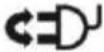 | L and N conductors have been switched (voltage between terminals PE and N). |
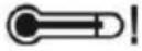 | The temperature inside the meter has risen above the limit, the measurement is blocked. |
 | RCD is inactive. |
| [DS3K] | Safe contact voltage exceeded. |
 | RE value is out of range. |
| [HD26] | The measurement cancelled with ESC. |
| [YBW4] | The loss of voltage during the measurement. |
 | After UB RE measurement, IA (or tA) measurement has not been performed because the values of RE and mains voltage did not allow to generate the required current value. |
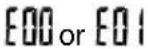 | Damaged current setting circuit. Try to perform measurement again. If the message reappears, please send the meter for repair. |
2.6.2 Measurement of RCD disconnection time
①
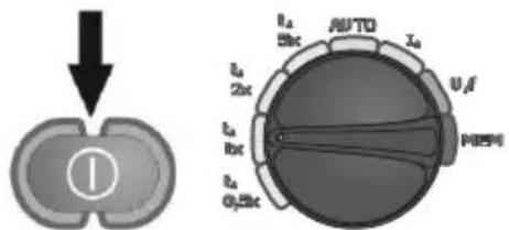
Turn on the meter. Turn the rotary switch to a position for tA measurement with selected multiplication factor of I_An .
②
Set the parameters according to the following algorithm, and according to the rules described in general parameters setting.
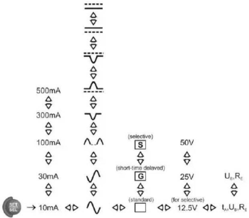
Parameter | I_ n | Current waveform | Type of switch | U_L | Measurement mode
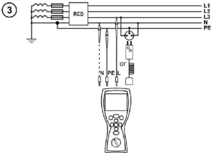
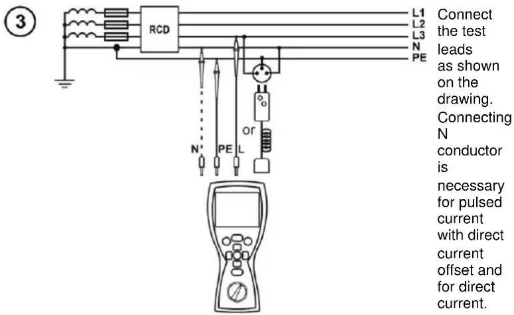
Connect the test leads as shown on the drawing. Connecting N conductor is necessary for pulsed current with direct current offset and for direct current.
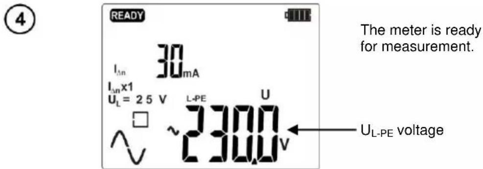
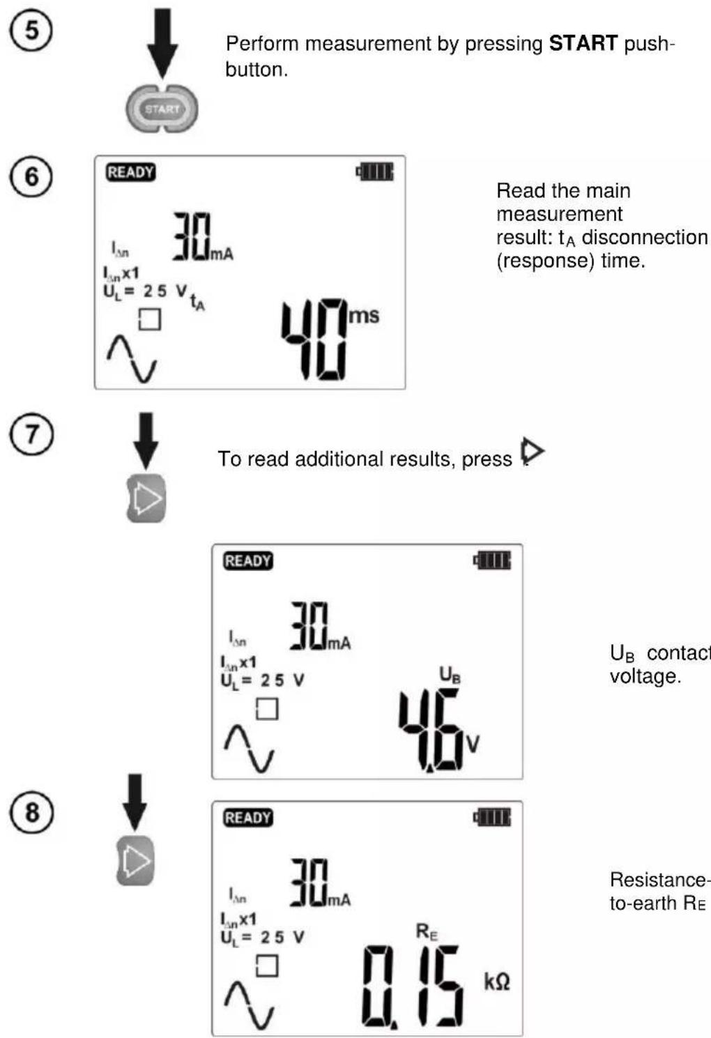
Perform measurement by pressing START push-button.
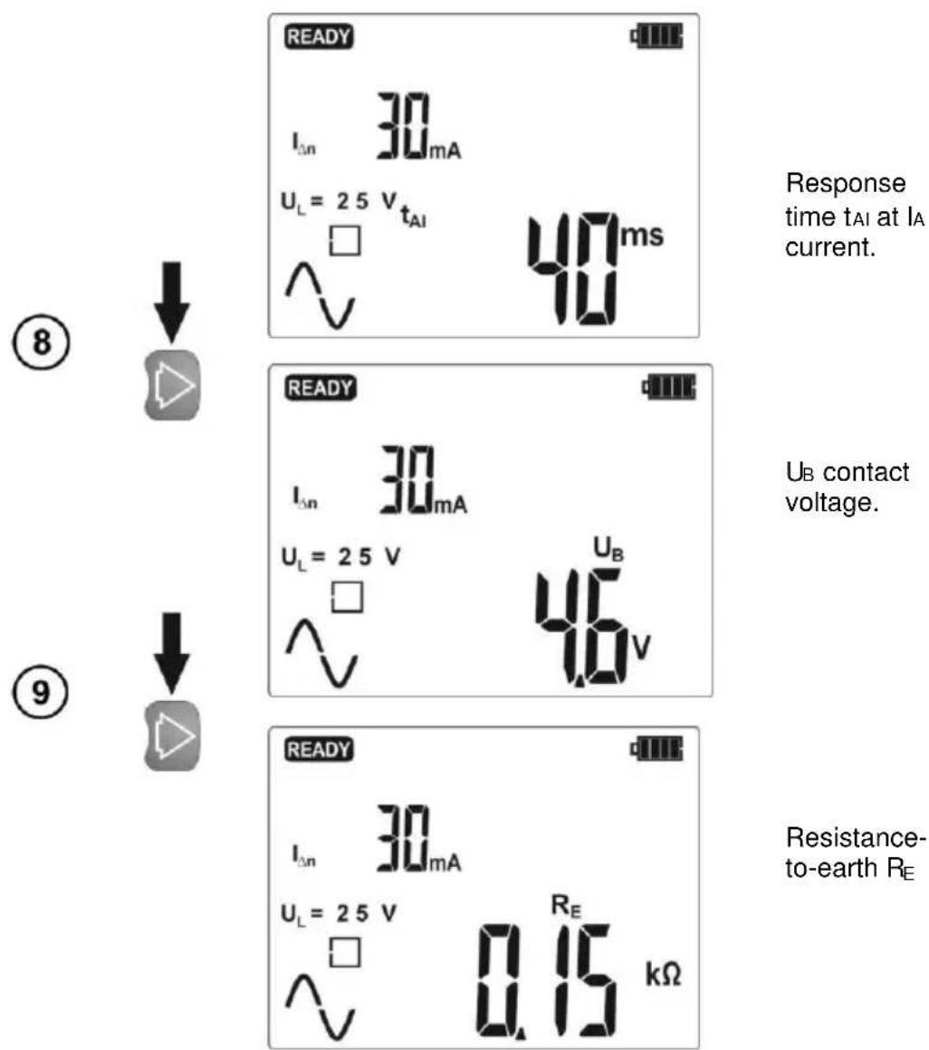
Read the main measurement result: t_A disconnection (response) time.
To read additional results, press
U_B contact voltage.
Resistance-to-earth R_E
Messages and information displayed by the meter as in Section 2.6.1.
2.6.3 Automatic measurement of RCD parameters
The meter enables automatic measurement of the following: RCD disconnection times ( t_A ), disconnection current ( I_A ), touch voltage ( U_B ) and resistance-to-earth ( R_E ). In this mode, there is no need to trigger the measurement foe every single measurement and the role of the user is reduced to initiate the measurement and switch on RCD after each tripping.
MRP-201 provides two AUTO modes to be chosen from the main menu:
- FULL mode
- STANDARD mode
Mode selection is described in Section 2.1.
2.6.3.1 FULL mode
①
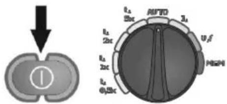
Turn on the meter. Turn the rotary switch to AUTO position.
②
If displayed parameters differ from those required, set them according to the following algorithm, and according to the rules described in general parameters setting.
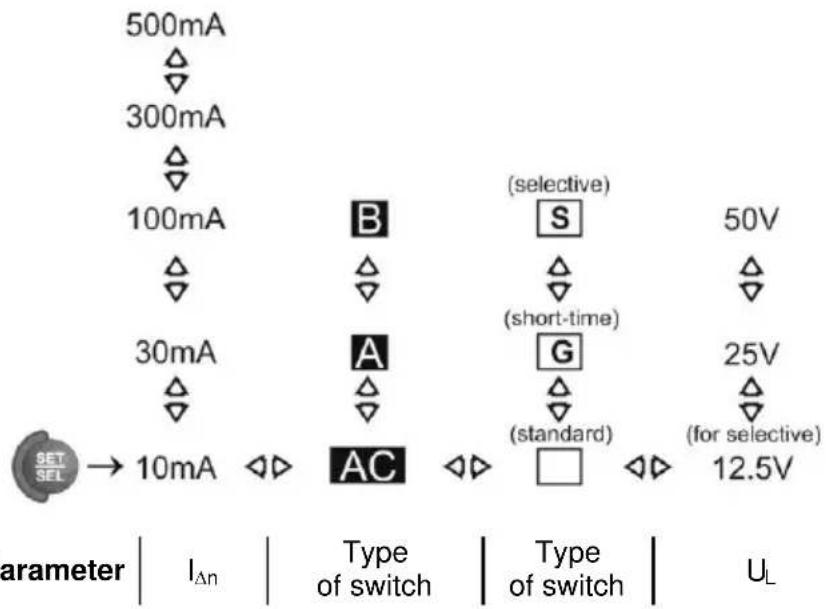
other
| Parameter | Type of switch | Voltage | Type of switch | | :--- | :--- | :--- | :--- | | SET SEL → 10mA | I_Δn | 500mA | △ | | SET SEL → 10mA | I_Δn | 300mA | ▽ | | SET SEL → 10mA | I_Δn | 100mA | △ | | SET SEL → 10mA | I_Δn | 30mA | △ | | SET SEL → 10mA | I_Δn | 10mA | ◇▶ | | Selective (B) | △ | 50V | ▶ | | Selective (S) | △ | 50V | △ | | Selective (A) | △ | short-time | △ | | Selective (G) | △ | 25V | ▶ | | Selective (G) | △ | 25V | △ | | Selective (G) | △ | (standard) | ▽ | | Selective (G) | △ | (for selective) | ▽ | | Selective (□) | ▽ | 12.5V | ▽▶ | Parameter | Type of switch | Type of switch | U_L③
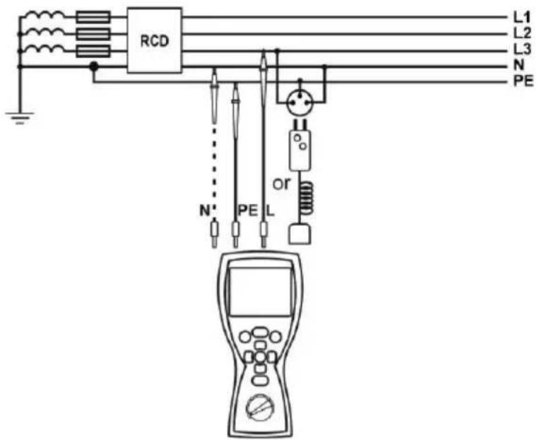
Connect test leads according to the drawing. Connecting N conductor is necessary for pulsed current with direct current offset and for direct current.
④
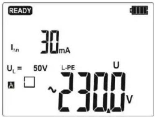
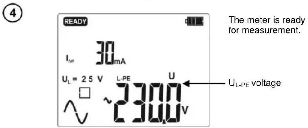
The meter is ready for measurement.
UL-PEvoltage
⑤
Press START push-button to start measurement.
⑥
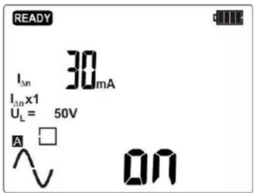
After each activation turn on tested RCD.
⑦
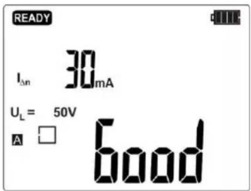
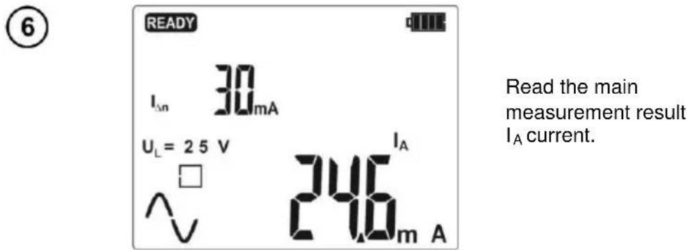
Read the main measurement result: Good - good or b-Ad bad.
Enter the result into memory by pressing ENTER, or see the components of the result and go to displaying voltage values by pressing ESC. The meter provides the following measurements:
For RCD AC:
| No. | Parameters measured | Measurement conditions | |
| I_ n multiplication factor | Initial phase (polarization) | ||
| 1. | U_B, R_E | ||
| 2. | t_A^ | 0.5I_ n | positive |
| 3. | t_A^ | 0.5I_ n | negative |
| 4.* | t_A^ | 1I_ n | positive |
| 5.* | t_A^ | 1I_ n | negative |
| 6.* | t_A^ | 2I_ n | positive |
| 7.* | t_A^ | 2I_ n | negative |
| 8.* | t_A^ | 5I_ n | positive |
| 9.* | t_A^ | 5I_ n | negative |
| 10.* | I_A^ | positive | |
| 11.* | I_A^ | negative | |
* points in which an efficient RCD should be disconnected
For RCD A:
| No. | Parameters measured | Measurement conditions | |
| I_ n multiplication factor | Initial phase (polarization) | ||
| 1. | U_B, R_E | ||
| 2. | t_A^ | 0.5 I_ n | positive |
| 3. | t_A^ | 0.5 I_ n | negative |
| 4.* | t_A^ | 1 I_ n | positive |
| 5.* | t_A^ | 1 I_ n | negative |
| 6.* | t_A^ | 2 I_ n | positive |
| 7.* | t_A^ | 2 I_ n | negative |
| 8.* | t_A^ | 5 I_ n | positive |
| 9.* | t_A^ | 5 I_ n | negative |
| 10.* | I_A^ | positive | |
| 11.* | I_A^ | negative | |
| 12.* | t_A^ | 0.5 I_ n | positive |
| 13.* | t_A^ V' | 0.5 I_ n | negative |
| 14.* | t_A^ | 1 I_ n | positive |
| 15.* | t_A^ V' | 1 I_ n | negative |
| 16.* | t_A^ | 2 I_ n | positive |
| 17.* | t_A^ V' | 2 I_ n | negative |
| 18.* | t_A^ | 5 I_ n | positive |
| 19.* | t_A^ V' | 5 I_ n | negative |
| 20.* | I_A^ | positive | |
| 21.* | I_A^ V' | negative | |
| 22.* | t_A^ | 0.5 I_ n | positive |
| 23.* | t_A^ V' | 0.5 I_ n | negative |
| 24.* | t_A^ | 1 I_ n | positive |
| 25.* | t_A^ V' | 1 I_ n | negative |
| 26.* | t_A^ | 2 I_ n | positive |
| 27.* | t_A^ V' | 2 I_ n | negative |
| 28.* | t_A^ | 5 I_ n | positive |
| 29.* | t_A^ V' | 5 I_ n | negative |
| 30.* | I_A^ | positive | |
| 31.* | I_A^ V' | negative | |
* points in which an efficient RCD should be disconnected
For RCD B:
| No. | Parameters measured | Measurement conditions | |
| I_An multiplication factor | Initial phase (polarization) | ||
| 1. | U_B, RE | ||
| 2. | t_A^ | 0.5I_ n | positive |
| 3. | t_A^ | 0.5I_ n | negative |
| 4.* | t_A^ | 1I_ n | positive |
| 5.* | t_A^ | 1I_ n | negative |
| 6.* | t_A^ | 2I_ n | positive |
| 7.* | t_A^ | 2I_ n | negative |
| 8.* | t_A^ | 5I_ n | positive |
| 9.* | t_A^ | 5I_ n | negative |
| 10.* | I_A^ | positive | |
| 11.* | I_A^ | negative | |
| 12.* | t_A^ | 0.5I_ n | positive |
| 13.* | t_A^ V^ | 0.5I_ n | negative |
| 14.* | t_A^ | 1I_ n | positive |
| 15.* | t_A^ V^ | 1I_ n | negative |
| 16.* | t_A^ | 2I_ n | positive |
| 17.* | t_A^ V^ | 2I_ n | negative |
| 18.* | t_A^ | 5I_ n | positive |
| 19.* | t_A^ V^ | 5I_ n | negative |
| 20.* | I_A^ | positive | |
| 21.* | I_A^ V^ | negative | |
| 22.* | t_A^ | 0.5I_ n | positive |
| 23.* | t_A^ V^ | 0.5I_ n | negative |
| 24.* | t_A^ | 1I_ n | positive |
| 25.* | t_A^ V^ | 1I_ n | negative |
| 26.* | t_A^ | 2I_ n | positive |
| 27.* | t_A^ V^ | 2I_ n | negative |
| 28.* | t_A^ | 5I_ n | positive |
| 29.* | t_A^ V^ | 5I_ n | negative |
| 30.* | I_A^ | positive | |
| 31.* | I_A^ V^ | negative | |
| 32.* | t_A^ | 0.5I_ n | positive |
| 23.* | t_A^ | 0.5I_ n | negative |
| 24.* | t_A^ | 1I_ n | positive |
| 25.* | t_A^ | 1I_ n | negative |
| 26.* | t_A^ | 2I_ n | positive |
| 27.* | t_A^ | 2I_ n | negative |
| 28.* | t_A^ | 5I_ n | positive |
| 29.* | t_A^ | 5I_ n | negative |
| 30.* | I_A^ | positive | |
| 31.* | I_A^ | negative | |
* points in which an efficient RCD should be disconnected
Notes:
- The number of measured parameters depends on the settings entered in the main menu.
- U_B and R_E are always measured.
- Automatic measurement is interrupted in the following cases:
- the switch was tripped during the measurement of U B RE or tA at the half value of IΔn,
- the switch did not trip during other component measurements,
- the value of safe voltage U_L has been exceeded,
• voltage was disconnected during one of the component measurements, - the values of R_E and mains voltage did not allow to generate the required current value for one of component measurements.
- The meter automatically skips the measurements impossible to perform, e.g. the value of selected I_ n current and its multiplication factor exceed the testing range of the meter.
- Criteria for assessing the correctness of component results:
- 0.5^I_ n≤ I_A ≤ 1^I_ n
- 0,35^I_ n≤ I_A and ≤ 2^I_ n for I_ n = 10mA
- 0,35^I_ n≤ I_A and ≤ 1,4^I_ n for remaining I_ n
- 0.5^I_ n≤ I_A ≤ 2^I_ n
• t A at 0.5*I n → rcd, for all types of RCD
• t A at 1*I n ≤ 300ms for standard RCD's - t A at 2^*I n ≤ 150 ms for standard RCD's
• t A at 5*I _ n ≤40ms for standard RCD's - 130ms≤ t_A at 1^*I_ n≤ 500ms for selective RCD's
- 60ms≤ t_A at 2^*I_ n≤ 200ms for selective RCD's
- 50ms≤ t_A at 5^*I_ n≤ 150ms for selective RCD's
- 10ms≤ t_A at 1^*|_ n≤ 300ms for short-time delay RCD's
- 10ms≤ t_A at 2^*I_ n≤ 150ms for short-time delay RCD's
- 10ms≤ t A at 5^*I_ n≤ 40ms for short-time delay RCD's
Additional information displayed by the meter
| Good | RCD in good working order. |
| bAd | RCD not in god working order. |
| on | Switch on the RCD. |
Other information displayed by the meter as in Section 2.6.1.
2.6.3.2 STANDARD mode
①
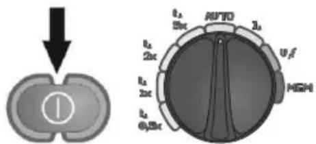
Turn on the meter.
Turn the rotary switch to
AUTO position.
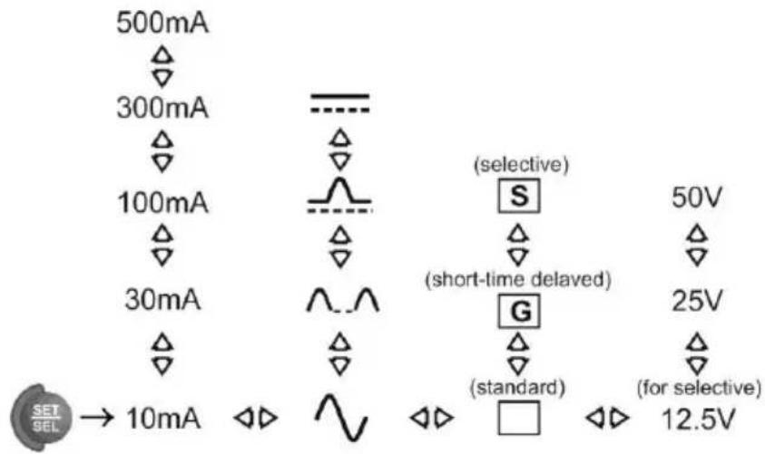
②
If displayed parameters differ from those required, set them according to the following algorithm, and according to the rules described in general parameters setting.

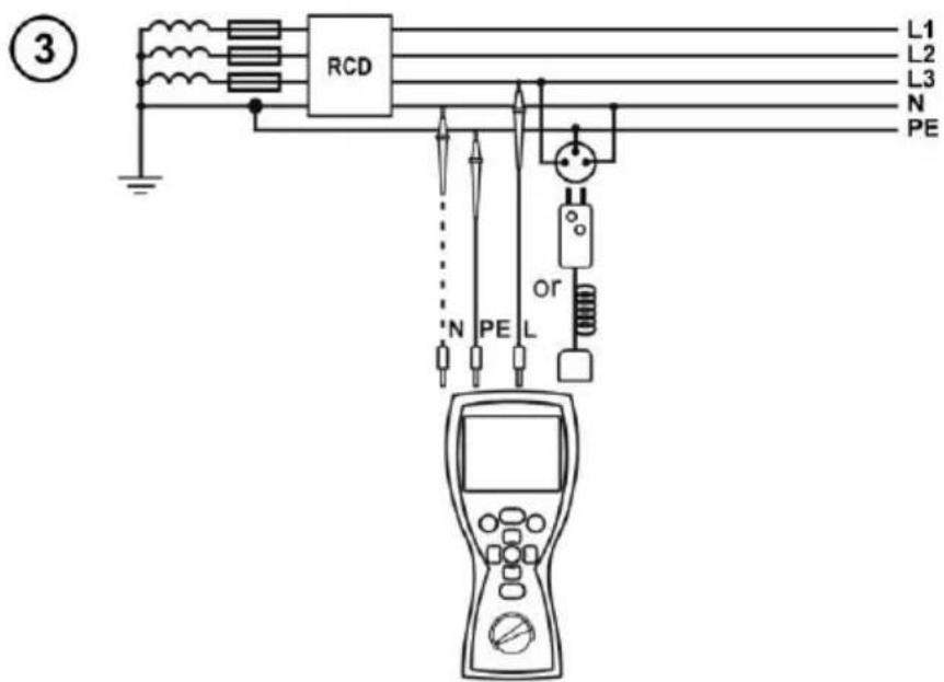
Connect test leads according to the drawing. Connecting N conductor is necessary for pulsed current with direct current offset and for direct current.
④
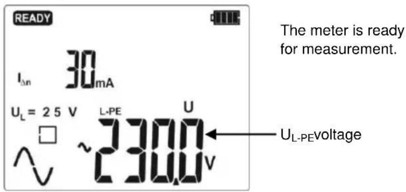
⑤
Press START push-button to start measurement.
⑥
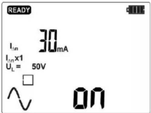
After each activation turn on tested RCD.
⑦
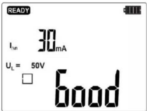
Read the main measurement result: bagod or bAd - bad.
Notes:
- Measured parameters are the same as those presented in the table for FULL and RCD AC mode for selected current waveform.
- Other messages and information as in Section 2.6.3.1.
3 Memory of measurement results
MRP-201 meters are equipped with the memory that can store 10000 single measurement results. The whole memory is divided into 10 memory banks with 99 cells in each bank. Thanks to dynamic memory allocation, each of the memory cells can contain different quantity of single measurement results, depending on the needs. Optimal use of the memory can be ensured in this way. Each measurement result can be stored in a memory cell marked with a selected number and in a selected memory bank. Thanks to this, the user of the meter can, at his/her option, assign memory cell numbers to individual measurement points and the memory bank numbers to individual facilities. The user can also perform measurements in any sequence and repeat them without losing other data.
Memory of measurement results is not deleted when the meter is switched off. Thanks to this, the data can be later read or sent to a computer. The number of a current memory cell or memory bank is not changed either.
Note:
- Results of measurements performed for all measuring functions can be stored in one memory cell.
- After each entry of the measurement result to the cell, its number is automatically incremented. Set the appropriate cell number to allow entering to a single cell of successive measurement results relating to a given measuring point (facility).
- Only the results of measurements triggered by START push-button may be stored in the memory.
- It is recommended to delete the memory after reading the data or before performing a new series of measurements that may be stored into the same memory cells as the previous ones.
3.1 Storing the measurement result data in the memory
①
Press ENTER after completion of the measurement.
The meter is in the memory storing mode.
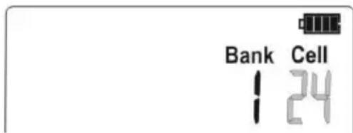
The cell number is flashing.
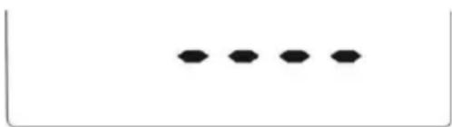
natural_image
Four black oval shapes arranged horizontally within a rectangular border (no text or symbols)Cell is empty.
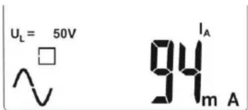
The cell contains the result of the same type which is to be entered.
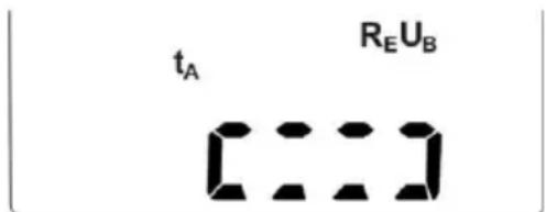
The cell contains the measurement results of the displayed types.
After 5s the first result displayed.
②
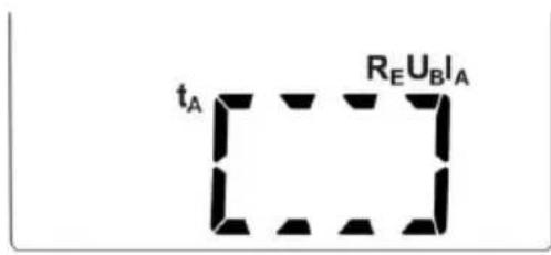
The cell contains the measurement results of all types. After 5s the first result displayed.
Use and buttons to view different types of results.
③
Select the bank and cell number (see section 3.2) or leave the current number. Then press ENTER again. The following screen appears for a moment, accompanied by three short beeps, and then the meter returns to display the last result of the measurement.
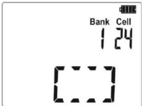
④
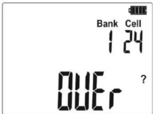
An attempt to overwrite a result causes the warning symbol to appear.
⑤
flowchart
graph TD
    A["ENTER"] --> B["ESC"]
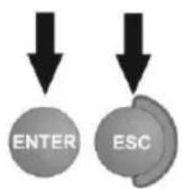
Press ENTER to overwrite the result or ESC to abort.
Notes:
- In case of RCD's the above warning message will appear also when an attempt is made to store a result of specific measurement (or result component) that has been made at different preset of I current or for a different type of RCD set (standard / short-time delay / selective) than the measurements the results of which are already stored in this cell, despite the fact that the memory space designated for this result component may be free. When results of measurements made for a different type of RCD or a different I _ n current are stored, the results concerning a given RCD that have been stored previously will be lost. - Complete set of results (main result and supplementary results) for a given measuring function and preset measurement settings are stored in the memory.
3.2 Changing the cell and bank number
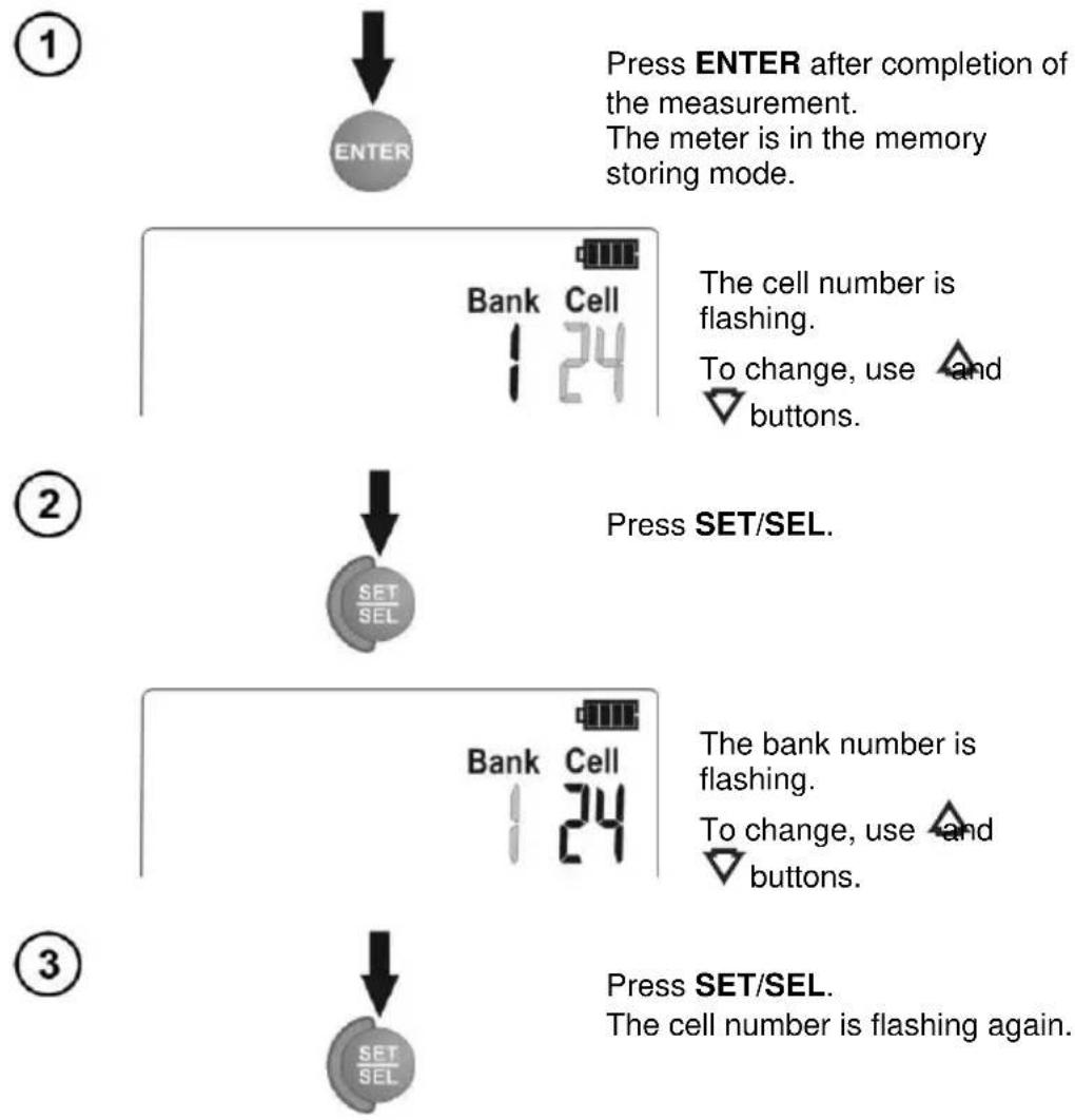
flowchart
graph TD
    A["①"] --> B["ENTER"]
    B --> C["Press ENTER after completion of the measurement. The meter is in the memory storing mode."]
    C --> D["Bank Cell 24"]
    D --> E["The cell number is flashing. To change, use and buttons."]
    F["②"] --> G["SET/SEL"]
    G --> H["Press SET/SEL."]
    H --> I["Bank Cell 24"]
    I --> J["The bank number is flashing. To change, use and buttons."]
    K["③"] --> L["SET/SEL"]
    L --> M["Press SET/SEL. The cell number is flashing again."]
3.3 Viewing memory data
①
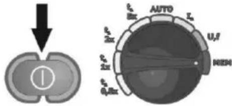
Turn on the meter. Turn the rotary switch to MEM position.
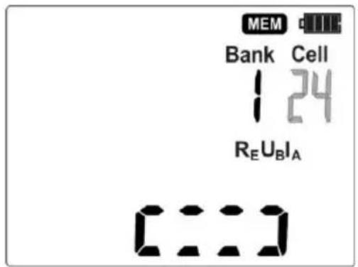
The symbol indicating the content of the cell saved as last, is displayed and after 5 seconds the first result is shown.
The cell number is flashing.
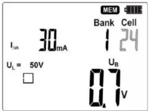
Use SET/SEL buttons and then and buttons.
To view the content of a cell, use
and buttons.
If the bank or cell number is flashing, its number can be changed.

3.4 Deleting memory data
3.4.1 Deleting bank data
①
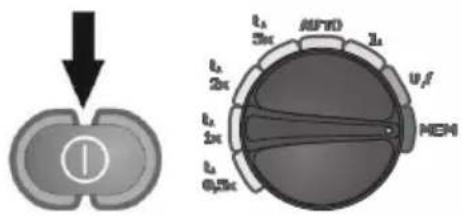
Turn on the meter. Turn the rotary switch to MEM position.
②
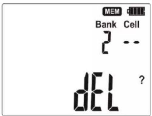
Set the bank number to be deleted according to section 3.2.
Set the cell number to (before 1). The symbol appears which indicates the readiness to delete.
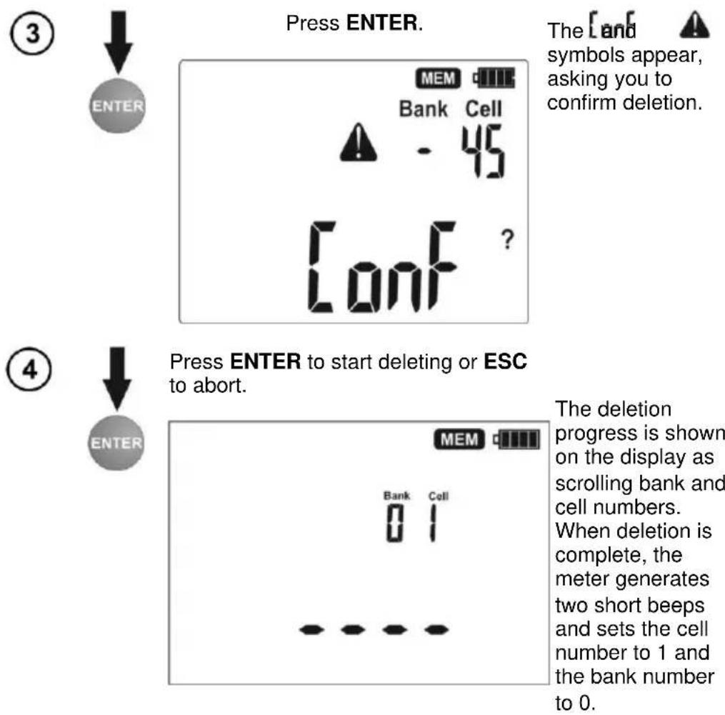
③
Press ENTER.
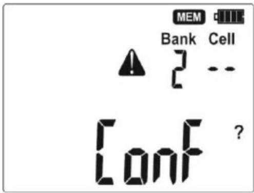
The [and] symbols appear, asking you to confirm deletion.
④
Press ENTER to start deleting or ESC to abort.
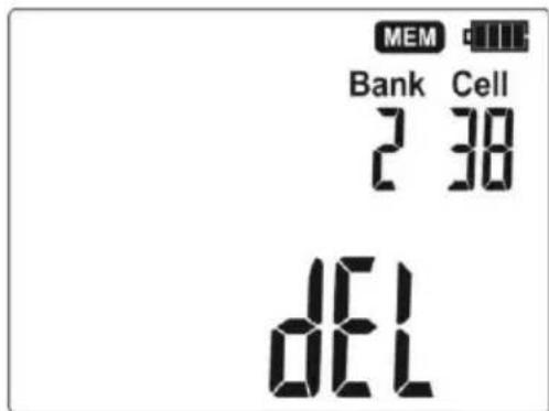
The deletion progress is shown on the display as scrolling cell numbers. When deletion is complete, the meter generates two short beeps and sets the cell number to 1 and the bank number to 0.
3.4.2 Deleting the whole memory
①
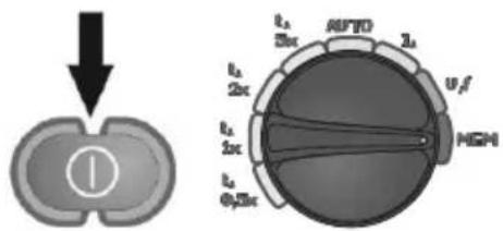
Turn on the meter. Turn the rotary switch to MEM position.
②
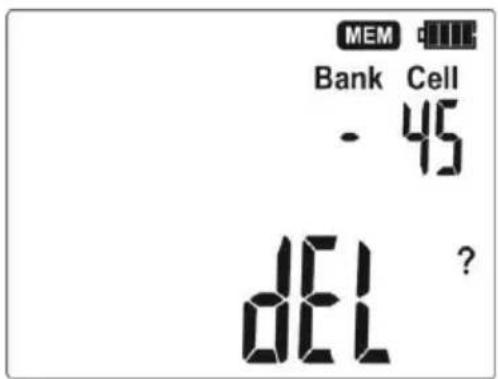
Set the bank number to -(before 0). The symbol DEL appears which indicates the readiness to delete.
3.5 Communication with PC
3.5.1 Computer connection accessories
What is necessary in order to operate the meter with a computer is additional accessories, namely an OR-1 receiver and appropriate software. If this package has not been purchased along with the meter, it can be bought from the manufacturer or an authorized distributor where detailed software information is also available.
3.5.2 Data transmission
①
Connect OR-1 module to the USB socket of the PC.
②
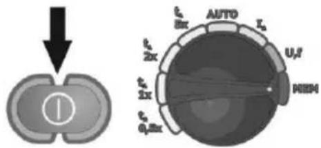
Turn on the meter. Turn the rotary switch to MEM position.
③
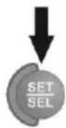
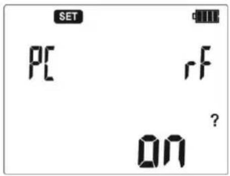
Press SET/SEL for about 2 seconds; the meter will ask you to activate the radio transmission.
④
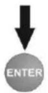
Press ENTER; the radio transmission screen will appear.
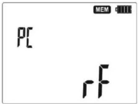
To transmit data, follow the instructions of the software. Press ESC to exit the transmission mode.
Note:

PIN code of an application must be compatible with the PIN code of the meter defined in main settings. Standard pin for OR-1 is "123".
4 Troubleshooting
Before returning the instrument for repair, call the service, perhaps the meter is not damaged, and the problem has occurred for another reason.
The meter repairs should be carried out only in the outlets authorized by the manufacturer.
The following table describes the recommended procedure in certain situations that occur when using the meter.
| Symptom | Cause | Action |
| The meter does not start after pressing button 0During the voltage measurement the following symbol is displayed: bAtThe meter turns off during the initial test. | Discharged or incorrectly placed batteries/rechargeable batteries. | Check if the batteries are placed correctly, replace and/or recharge the rechargeable batteries. If this does not help, sent the meter for servicing. |
| Measurement errors after moving the meter from cold environment to warm and humid environment. | No acclimatization. | Do not perform the measurements until the meter reaches the ambient temperature (about 30 minutes) and dries. |
| Consecutive results obtained in the same measuring point are significantly different from each other. | Incorrect connections in the tested installation. | Check the connections and remove defects. |
| The network with high noise or unstable voltage. | Perform a larger number of measurements, average the results. | |
| During contact voltage measurement or earth resistance, RCD is tripped (RCD is tripped already at 40% of IΔn set value). | The set value of IΔn is to high. | Set correct IΔn. |
| Relatively high leakage currents in the installation. | Reduce leakage currents. | |
| Error in the installation. | Verify the correctness of N and PE connections. | |
| During the test the switch is not tripping. | The set value of IΔn is to low. | Set correct IΔn. |
| Improper current waveform setting. | Set the proper current waveform. | |
| RCD damaged. | Test RCD by pressing TEST button, or replace RCD. | |
| Error in the installation. | Verify the correctness of N and PE connections. | |
| During measurements of RCD disconnection current r symbol is displayed, although the switch was tripped. | Tripping time is longer than the measurement time. | RCD switch should be considered as faulty. |
| Large differences between the results of repeated measurements of the tripping time for the same RCD. | Initial magnetization of the transformer core inside the RCD. | It is normal for some direct-acting RCDs; try to perform further measurements with opposite polarities of differential current. |
| Performing t_A or I_A measurement is impossible. | Contact voltage, which is generated during t_A or I_A measurement, may exceed the value of safe voltage - then the measurement is automatically blocked. | Check the connections of the protective conductor |
| Verify the selection of RCD in relation to the rated differential current. | ||
| The set value of I_ n is to high. | Set correct I_ n . | |
| Unstable measurement result foe U_B or R_E , i.e. the results of successive measurements performed at the same point of installation differ significantly from each other. | Significant leakage currents have high variability. | |
| Symbol does not appear, although the voltage between the contact electrode and PE conductor exceeds the detector threshold (about 50V). | Contact electrode is not functioning correctly or the meter input circuits are damaged. | Return the meter for servicing; using a malfunctioning meter is unacceptable |
5 Meter power supply
5.1 Monitoring of the power supply voltage
The charge level of the batteries or rechargeable batteries is indicated by the symbol in the right upper corner of the display on a current basis:
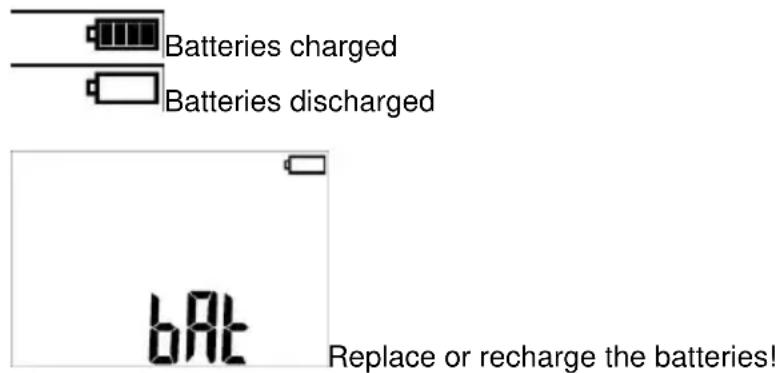
Note:
- The symbol in the display means that the supply voltage is too low and indicates that the batteries must be replaced or recharged,
- Measurements performed with an insufficient supply voltage feature additional errors which the user is unable to evaluate.
5.2 Replacing batteries (rechargeable batteries)
MRP-201 is powered by four R6 disposable or rechargeable batteries (alkaline batteries are recommended). The (rechargeable) batteries are placed in the compartment at the bottom of the enclosure.
WARNING: Before replacing the batteries, disconnect the test leads from the meter.
To replace the batteries:
- Disconnect the leads from the measuring circuit and turn off the meter,
- Remove the screw that secures the battery cover (the bottom of the enclosure),
- Replace all batteries. Observe the correct polarity when putting new batteries ("-" on the elastic part of the contact plate). Reverse polarity will not damage the meter or the batteries, but the meter will not work.
- Place and tighten the battery compartment cover.
After replacing batteries/rechargeable batteries and turning on the meter, it starts in the power supply source selection mode.
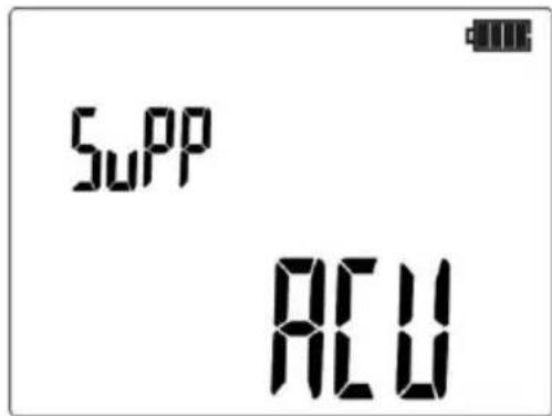
Selected power source: rechargeable batteries.
Use and buttons to switch between disposable and rechargeable batteries.
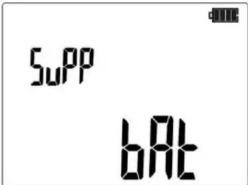
Press ENTER to validate the choice. The meter goes to the measurement readiness mode.
NOTE!
After replacing the batteries/rechargeable batteries, always set the power supply type. The correct charge indication depends on this setting (the discharge characteristics of disposable and rechargeable batteries are different).
NOTE!
Have the meter serviced in case of battery leakage inside the compartment.
Rechargeable batteries must be recharged in an external charger.
5.3 General principles regarding using Ni-MH accumulators
- If you do not use the device for a prolonged period of time, then it is recommended to remove the accumulators and store them separately.
- Store the accumulators in a dry, cool and well ventilated place and protect them from direct sunlight. The temperature of the environment in the case of prolonged storage should not exceed 30^a C. If the accumulators are stored for a long time in a high temperature, then the occurring chemical processes may reduce their lifetime.
- Accumulators NiMH resist normally 500-1000 charging cycles. The accumulators reach their maximum capacity after being formatted (2-3 charge and discharge cycles). The most important factor which influences the lifetime of an accumulator is the depth of discharge. The deeper the discharge of the accumulator, the shorter its lifetime.
- The memory effect is limited in the case of NiMH accumulator. These accumulators may be charged at any point with no serious consequences. However, it is recommended to discharge them completely every few cycles.
- During storage of Ni-MH accumulators they are discharged at the rate of approximately 30% per month. Keeping accumulators at high temperatures may accelerate this process even 100%. In order to prevent excessive discharge of accumulators, after which it would be necessary to format them, it is recommended to charge the accumulators from time to time (even if not in use).
- Modern fast chargers detect both too low and too high a temperature of accumulators and react to the situation adequately. Too low a temperature should prevent the start of the process of charging, which might damage the accumulator irreparably. An increase of the temperature of the accumulator is a signal to stop charging and is a typical phenomenon. However charging at a high temperature of the environment apart from reducing the lifetime causes an accelerated increase of the temperature of the accumulator, which will be not charged to its full capacity.
- Remember that in the case of quick charging accumulators are charged to approximately 80% of their capacity; better results may be obtained if the process of charging is continued: the charger goes then to the phase of charging with a low current and after next couple of hours the accumulators are charged to their full capacity.
- Do not charge or use accumulators in extreme temperatures. Extreme temperatures reduce the lifetime of batteries and accumulators. Avoid placing devices powered from accumulators in very hot environments. The nominal working temperature must be absolutely observed.
6 Cleaning and maintenance
NOTE!
Apply solely the maintenance methods specified by the manufacturer within the present manual.
The casing of the meter may be cleaned with a soft, damp cloth using all-purpose detergents. Do not use any solvents or cleaning agents which might scratch the casing (powders, pastes, etc.). The electronic system of the meter does not require maintenance.
7 Storage
In the case of storage of the device, the following recommendations must be observed:
- Disconnect all the test leads from the meter.
- Clean the meter and all its accessories thoroughly.
- In the case the meter is to be stored for a prolonged period of time, the batteries must be removed from the device.
- In order to prevent a total discharge of the accumulators in the case of a prolonged storage, charge them from time to time.
8 Dismantling and utilisation
Worn-out electric and electronic equipment should be gathered selectively, i.e. it must not be placed with waste of another kind.
Worn-out electronic equipment should be sent to a collection point in accordance with the law of worn-out electric and electronic equipment.
Before the equipment is sent to a collection point, do not dismantle any elements.
Observe the local regulations concerning disposal of packages, worn-out batteries and accumulators.
9 Technical specifications
9.1 Basic data
⇒ Abbreviation "m.v." used in the specification of accuracy means a standard measured value.
Voltage measurement
| Range | Resolution | Accuracy |
| 0.0 ... 299.9V | 0.1V | ±(2% m.v. + 6 digits) |
| 300...500V | 1V | ±(2% m.v. + 2 digits) |
• Frequency range: 45...65Hz
Frequency measurement
| Range | Resolution | Accuracy |
| 45.0 ... 65.0 Hz | 0.1Hz | ±(0.1% m.v. + 1 digit) |
• Voltage range: 50 .. 500V
Measurement of parameters of RCD
- Rated operating voltage U _n : 220V, 230V, 240V
- Operating voltage range: 180...270V
- Rated mains frequency f_n : 50Hz, 60Hz
- Operating frequency range: 45...65Hz
• Control of correctness of PE terminal connection by means of a contact electrode
RCD trigger and response time test t_A (for t_A measuring mode)
Test range according to IEC 61557: 0ms ... to the upper limit of displayed value
| Type of RCD | Setting of multiple values | Test range | Resolution | Accuracy |
| General type and short time delay | 0.5 I_ n | 0..300 ms | 1 ms | ± 2% m.v. ±2 digits ^1) |
| 1 I_ n | ||||
| 2 I_ n | 0..150 ms | |||
| 5 I_ n | 0..40 ms | |||
| Selective | 0.5 I_ n | 0..500 ms | ||
| 1 I_ n | ||||
| 2 I_ n | 0..200 ms | |||
| 5 I_ n | 0..150 ms |
^1) for I_ n = 10mA and 0.5I_ n uncertainty is ± 2% m.v. ± 3 digits
• Accuracy of differential current setting:
for 1^I_ n , 2^I_ n and 5^*I_ n 0.8%
for 0.5^*I_ n -8..0%
- RCD tripping time may depend on: the number of RCD trippings in the previous measurements, devices connected to the system, leakage currents in the system, etc. When results of measurements obtained in AUTO mode raise doubts, repeat the measurements in single mode.
Effective value of forced leakage current at measurement of RCD disconnection time
| I_ n | Multiplication factor setting | |||||||
| 0.5 | 1 | |||||||
| ~ | ^^ | ^^ | === | ~ | ^^ | ^^ | === | |
| 10 | 5 | 3.5 | 3.5 | 5 | 10 | 20 | 20 | 20 |
| 30 | 15 | 10.5 | 10.5 | 15 | 30 | 42 | 42 | 60 |
| 100 | 50 | 35 | 35 | 50 | 100 | 140 | 140 | 200 |
| 300 | 150 | 105 | 105 | 150 | 300 | 420 | 420 | 600 |
| 500 | 250 | 175 | 175 | 250 | 500 | — | — | — |
| I_ n | Multiplication factor setting | |||||||
| 2 | 5 | |||||||
| == | == | |||||||
| 10 | 20 | 40 | 40 | 40 | 50 | 100 | 100 | 100 |
| 30 | 60 | 84 | 84 | 120 | 150 | 210 | 210 | 300 |
| 100 | 200 | 280 | 280 | 400 | 500 | — | — | — |
| 300 | 600 | — | — | — | — | — | — | — |
| 500 | — | — | — | — | — | — | — | — |
Measurement of resistance-to-earth RE
| Selected nominal current of switch | Test range | Resolution | Test current | Accuracy |
| 10 mA | 0.01kΩ..5.00 kΩ | 0.01 kΩ | 4 mA | 0..+10%m.v. ±8 digits |
| 30 mA | 0.01kΩ..1.66kΩ | 12 mA | 0..+10%m.v. ±5 digits | |
| 100 mA | 1 Ω..500 Ω | 1 Ω | 40 mA | 0..+5%m.v. ±5 digits |
| 300 mA | 1 Ω..166 Ω | 120 mA | ||
| 500 mA | 1 Ω..100 Ω | 200 mA |
Measurement of contact voltage U_B in relation to nominal differential current
Test range according to IEC 61557: 10.0 ... 99.9 V
| Test range | Resolution | Test current | Accuracy |
| 0..9.9 V | 0.1 V | 0.4 × I_ n | 0..10% m.v. ± 5 digits |
| 10.0..99.9 V | 0..15% m.v. |
Measurement of RCD disconnection current I_A for sinusoidal differential current
Test range according to IEC 61557: (0.3...1.0)IΔn
| Selected nominal current of RCD | Test range | Resolution | Test current | Accuracy |
| 10 mA | 3.0..10.0 mA | 0.1 mA | 0.3 × I_ n..1.0 × I_ n | ±5 % I_ n |
| 30 mA | 9.0 .. 30.0 mA | |||
| 100 mA | 30..100 mA | 1 mA | ||
| 300 mA | 90..300 mA | |||
| 500 mA | 150..500 mA |
- it is possible to start the measurement from the positive or the negative half-period of forced leakage current
- test current passage time at f = 50.0Hz.... max. 7510 ms
Measurement of RCD disconnection current I_A for differential unidirectional pulsed current and unidirectional pulsed current with 6mA direct current offset
Test range according to IEC 61557: (0.15...1.4) I_ n for I_ n ≥ 30mA and (0,15...2) I_ n for I_ n = 10mA
| Selected nominal current of RCD | Test range | Resolution | Test current | Accuracy |
| 10 mA | 1.5..20.0mA | 0.1 mA | 0.15 × I_ n...2.0 × I_ n | ± 10 % I_ n |
| 30 mA | 4.5..42.0 mA | 0.15 × I_ n...1.4 × I_ n | ± 10 % I_ n | |
| 100 mA | 15..140mA | 1 mA | ||
| 300 mA | 45..420mA |
• measurement can be performed for positive or negative half-periods of forced leakage current
- test current passage time at f = 50.0Hz max. 14710 ms
Measurement of RCD disconnection current I_A for differential direct current
Test range according to IEC 61557: (0.2...2) I_ n
| Selected nominal current of RCD | Test range | Resolution | Test current | Accuracy |
| 10 mA | 2.0..20.0mA | 0.1 mA | 0.2 × I_ n..2.0 × I_ n | ±10 % I_ n |
| 30 mA | 6..60mA | 1 mA | ||
| 100 mA | 20..200mA | |||
| 300 mA | 60..600mA |
• measurement can be performed for positive or negative forced leakage current
- test current passage time at f = 50.0Hz...... max. 4500 ms
9.2 Other technical specifications
a) type of insulation acc. to EN 61010-1 and IEC 61557.....double
b) measurement category acc. to EN 61010-1.....IV 300V (III 600V)
c) degree of protection of enclosure acc. to EN 60529 IP67
d) power supply for the meter ..... alkaline batteries or NiMH rechargeable batteries size AA (4 pcs)
e) dimensions 220x98x58 mm
f) meter weight....approx 0.7 kg
g) storage temperature....-20...+70°C
h) operating temperature -10...+50°C
i) humidity....20...90%
j) reference temperature....+23 ± 2°C
k) reference humidity....40..60%
I) altitude (above sea level) .... <2000m
m) number of measurements (for rechargeable batteries) 6000 (2 measurements per minute)
n) display......LCD segment
o) memory of measurement results 990 cells, 10000 entries
p) data transmission....radio link, waveband ISM 433 MHz
q) quality standard...... development, design and manufacturing are ISO 9001 compliant
r) the device meets the requirements of the IEC 61557 standard
s) the product meets the EMC requirements (immunity for industrial environment) according to the following standards....EN 61326-1 and EN 61326-2-2
9.3 Additional data according to IEC 61557-6 (RCD)
Data on additional uncertainties are useful mainly when the meter is used in non-standard conditions and for metrological laboratories for the purpose of calibration.
I_A, U_B
| Significant parameter | Designation | Additional uncertainty |
| Position | E_1 | 0% |
| Supply voltage | E_2 | 0% (BAT is not lit) |
| Temperature 0...35°C | E_3 | 0% |
| Resistance of electrodes | E_5 | 0% |
| Mains voltage 85%..110% | E_8 | 0% |
t_A
| Significant parameter | Designation | Additional uncertainty |
| Position | E_1 | 0% |
| Supply voltage | E_2 | 0% (BAT is not lit) |
| Temperature 0...35°C | E_3 | 0.05% m.v./°C |
| Resistance of electrodes | E_6 | 0% |
| Mains voltage 85%..110% | E_8 | 0% |
10 Manufacturer
The manufacturer of the device, which also provides guarantee and post-guarantee service is the following company:
SONEL S.A.
Wokulskiego 11
58-100 Šwidnica
Poland
tel. +48 74 884 10 53 (Customer Service)
e-mail: customerservice@sonel.com
web page: www.sonel.com
Attention:
Service repairs must be realised solely by the manufacturer.
NOTES
NOTES
NOTES
WARNINGS AND GENERAL INFORMATION DISPLAYED BY THE METER
NOTE!
MRP-201 meter is designed to operate at the rated phase voltages 220V, 230V and 240V. Connection of the voltage higher than acceptable between any of the terminals may damage the meter and cause a hazard to the user.
 | The meter is ready for measurement. | ||
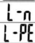 | Voltage on terminals L and N is within the measurable range. | ||
| Voltage on terminals L and PE is not within the measurable range. | |||
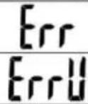 | Error in the measurement. | ||
| Error in the measurement: loss of voltage after the measurement. | |||
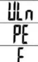 | Conductor N is not connected. | ||
| Incorrect connection of PE terminal, PE voltage > 50V. | |||
| Incorrect voltage frequency. | |||
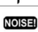 | This message displayed after the measurement indicates major nois in the system during the measurement. Then measurement result may be affected by a large unspecified error. | ||
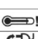 | The temperature inside the meter has risen above the limit.The measurement is blocked. | ||
| L and N conductors have been switched (voltage between terminals PE and N). | |||
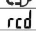 | The RCD has not tripped or has tripped during the measurement of UB, RE. | ||
 | Safe contact voltage exceeded. | ||
| RCD in good working order. | |||
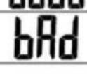 | RCD not in good working order. | ||
| KK5W] | Switch on the RCD. | ||
| > | Ω | Measuring range is exceeded. | |
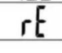 | The value of RE is exceeded for RCD. | ||
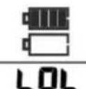 | Status of batteries/rechargeable batteries:ChargedDischarged | ||
| Batteries/rechargeable batteries fully discharged.Replace or recharge the batteries. |
SONEL S.A.
Wokulskiego 11
58-100 Świdnica
Poland
Customer Service
tel.+48 74 884 10 53
e-mail: customerservice@sonel.com
www.sonel.com
- USER MANUAL
- RCD TESTER
- RCD TESTER MRP-201
- CONTENTS
- Safety 4
- Measurements....5
- Memory of measurement results....21
- Troubleshooting....28
- Meter power supply 30
- Cleaning and maintenance 33
- Storage....33
- Dismantling and utilisation....33
- Technical specifications ....34
- Manufacturer ....37
- Safety
- ATTENTION!
- Note:
- Attention:
- Measurements
- WARNING:
- Selection of general measurement parameters
- Notes:
- Remembering the last measurement result
- Measurement of alternating voltage
- Measurement of voltage and frequency
- Validation of the connections the protective conductor
- Measurement of RCD parameters
- Measurement of RCD disconnection current
- Additional information displayed by the meter
- Measurement of RCD disconnection time
- Automatic measurement of RCD parameters
- FULL mode
- STANDARD mode
- Memory of measurement results
- Storing the measurement result data in the memory
- Changing the cell and bank number
- Viewing memory data
- Deleting memory data
- Deleting bank data
- Deleting the whole memory
- Communication with PC
- Computer connection accessories
- Data transmission
- Troubleshooting
- Meter power supply
- Monitoring of the power supply voltage
- Replacing batteries (rechargeable batteries)
- WARNING: Before replacing the batteries, disconnect the test leads from the meter.
- To replace the batteries:
- NOTE!
- General principles regarding using Ni-MH accumulators
- Cleaning and maintenance
- Storage
- Dismantling and utilisation
- Technical specifications
- Basic data
- Measurement of parameters of RCD
- RCD trigger and response time test t_A (for t_A measuring mode)
- Measurement of contact voltage U_B in relation to nominal differential current
- Measurement of RCD disconnection current I_A for sinusoidal differential current
- Measurement of RCD disconnection current I_A for differential unidirectional pulsed current and unidirectional pulsed current with 6mA direct current offset
- Measurement of RCD disconnection current I_A for differential direct current
- Other technical specifications
- Additional data according to IEC 61557-6 (RCD)
- Manufacturer
- SONEL S.A.
- WARNINGS AND GENERAL INFORMATION DISPLAYED BY THE METER
Brand : Sonel
Model : MRP-201
Category : Meter