
CHO-60PT070A X - Range hood Vivax - Free user manual and instructions
Find the device manual for free CHO-60PT070A X Vivax in PDF.

| Brand | Vivax |
| Model | CHO-60PT070A X |
| Product Type | Range Hood |
| Width | 60 cm |
| Installation | Under-cabinet or wall-mounted |
| Extraction Method | Ducted or recirculating (with charcoal filter) |
| Number of Speeds | 3 |
| Maximum Extraction Rate | Approximately 600 m³/h |
| Noise Level | 58 - 68 dB(A) |
| Lighting | 2 x LED lamps |
| Control Type | Electronic push button |
| Grease Filter | Aluminum mesh, dishwasher safe |
| Charcoal Filter | Optional, replaceable |
| Power Supply | 220-240 V ~ 50 Hz |
| Rated Power | 150 W (motor) + 2 x 2 W (lighting) |
| Weight | Approximately 10 kg |
| Dimensions (W x D x H) | 600 x 500 x 130 mm (with chimney: variable) |
| Duct Diameter | 150 mm |
| Energy Class | A+ (assumed) |
| Safety Features | Thermal overload protection |
Frequently Asked Questions - CHO-60PT070A X Vivax
User questions about CHO-60PT070A X Vivax
0 question about this device. Answer the ones you know or ask your own.
Ask a new question about this device
Download the instructions for your Range hood in PDF format for free! Find your manual CHO-60PT070A X - Vivax and take your electronic device back in hand. On this page are published all the documents necessary for the use of your device. CHO-60PT070A X by Vivax.
USER MANUAL CHO-60PT070A X Vivax
CHO-60CSA210A GB CHO-60CSA210A GW
CHO-60CHA210A GX
CHO-60CSA070A B
CHO-60CHA070AX
Kuhinjska napa
Zahvaljujemo što ste kupili ovu napu.
Ove upute za uporabu namijenjene su pružanju svih potrebnih uputa vezanih uz montažu, uporabu i održavanje uređaja.
Kako biste ispravno i sigurno mogli rukovati uređajem, pažljivo pročitajte upute prije montaže i korištenja.
Kuhinjska napa izrađena je od visokokvalitetnih materijala i moderno je dizajnirana. Opremljena je električnim motorom velike snage te centrifugalnim ventilatorom, ima snažnu usisnu snagu, nije bučna tijekom rada, ima nepropusni filtar za masnoću i jednostavno se montira.
VAŽNE SIGURNOSNE UPUTE

Simbol munje u trokutu upozorava korisnika na prisutnost opasnog napona koji nije izoliran unutar proizvoda i koji može biti dovoljno snažan da predstavlja rizik od strujnog udara.

Uskličnik unutar trokuta upozorava korisnika na važne upute za rad i održavanje u dokumentu priloženom u ambalaži.

OPREZ

RIZIK OD STRUJNOG UDARA NE OTVARAJ
Nemojte otvarati poklopac. Korisniku ni u kojem slučaju ne smije obavljati radove unutar uređaja. Samo kvalificirani tehničar ima pravo obavljati popravke. U slučaju nepridržavanja sigurnosnih uputa, proizvođač neće snositi odgovornost za štetu.
SIGURNOSNE NAPOMENE
natural_image
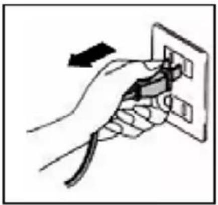
Diagram of airflow around a mechanical structure with directional arrows indicating movement (no text or symbols)b. Prije ugradnje isključite uređaj i izvucite kabel iz utičnice.
natural_image
Hand inserting a plug into an electrical outlet (no text or symbols visible)natural_image
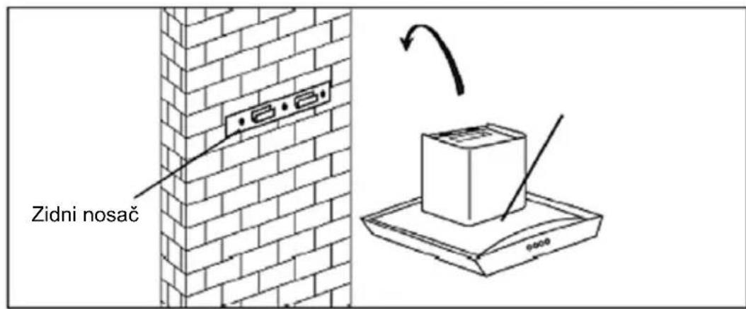
Pure geometric diagram of a 3D object with dashed lines and control points, no text or symbols present- Podignite kuhinjsku napu i objesite napu na nosač.

natural_image
Isometric line drawing of a brick wall with a small object on top, no text or symbols present
- Izbušite rupe od 2×8 mm koji će pridržavati nosač dimnjaka i pritegnite nosač na zid s dva predviđena vijka. Montirajte dimnjak na uređaj i učvrstite ga s 2 vijka za nosač.
natural_image
Technical line drawing of a chimney mounted on a brick wall, showing structural details without any text or symbols.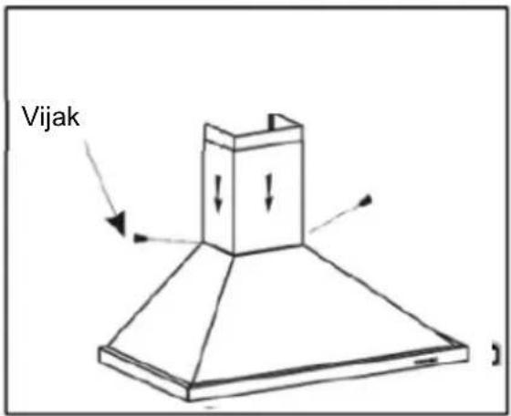
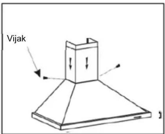
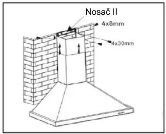
- Povucite unutarnji dimnjak kako biste postavili visinu dimnjaka. Kada dosegnete željenu visinu, tada pričvrstite 2 vijka od 4x8 mm na učvrsne rupe na zidnom nosaču "II" kao što je prikazano na desnoj slici.

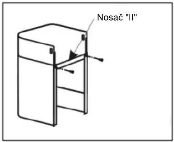
- Izbušite rupe od 2×8 mm za montiranje nosača "II" dimnjaka. Pričvrstite i pritegnite nosač na zid s dva predviđena vijka.
- Montirajte dimnjak na uređaj i učvrstite ga na nosač "II" s dva vijka.
natural_image
Diagram of a mechanical or fluid system with directional arrows indicating flow or movement (no text or symbols)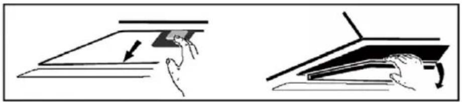
natural_image
Two-step diagram showing hand positioning of a rectangular object on a flat surface, with arrows indicating motion (no text or symbols)natural_image
Technical line drawing of a mechanical fan or motor assembly with no visible text or symbolsUPORABA
Mehanička / Elektronička kontrola

natural_image
Four circular icons with different leaf-like and sun-like symbols, arranged horizontally (no text or labels)Verzija 1
A. Okrugla LED rasveta (1,5W i 2W)
1.A Uklonite Aluminijskie filtre
2.A Odvojite LED lampu kako je prikazano i odspojite konektor napajanja LED lampe.
3 A Priključite novu LED lampu istog tipa i snage i vratite ju natrag u napu.
natural_image
Mechanical assembly diagram showing two wheels mounted on a rail, with directional arrows indicating motion (no text or symbols)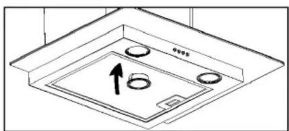
natural_image
Technical line drawing of a ceiling-mounted appliance with circular components and an upward arrow indicating direction (no text or symbols)B. 2W Kvadratna LED rasvjeta
1.B Uklonite Aluminijski filtar
2.B Odvojite LED
lampu kako je prikazano i odspojite konektor napajanja LED lampe.
Priključite novu LED lampu istog tipa i snage i vratite ju natrag u napu

RJEŠAVANJE PROBLEMA
natural_image
Diagram of airflow around a mechanical structure with directional arrows indicating movement (no text or symbols)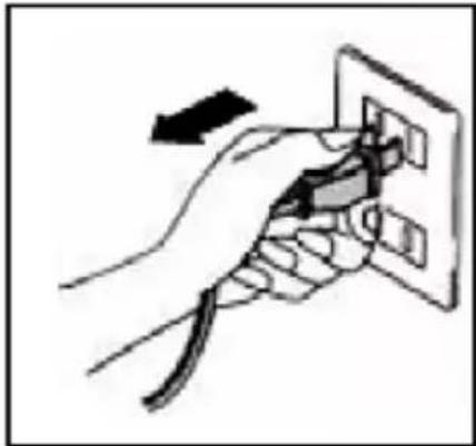
natural_image
Hand holding a power outlet plug with a cable, showing electrical connection (no text or symbols)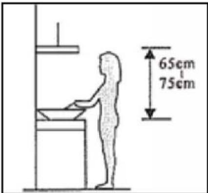
Oprez! Obratite pažnju na upozorenje u uputstvu o radu uređaja kada se vazduh ispušta iz prostorije.
Kada je aspirator instaliran pored kuhinjske ploče koji se snabdeva energijom koja nije električna (plinska ploča) i kada uređaji rade istovremeno, negativni pritisak u sobi ne sme biti veći od 4 Pa ( 4 × 10^5 bara)
- Izbušite rupe od 3 x 8 mm za montažu nosača. Postavite i pritegnite nosač na zid predviđenim tiplama i vijcima.
- Za model s nagnutom prednjom pločom, pre ugradnje trebate da izbušite dodatne rupe od 4 x 8 mm i pričvrstite nosač.
natural_image
Pure geometric diagram of a 3D object with dashed lines and control points, no text or symbols present- Podignite aspirator i objesite ga na nosač.
natural_image
Isometric line drawing of a brick wall with a small object on top, no text or symbols present
- Izbušite rupe od 2×8 mm koji će da pridržavaju nosač dimnjaka i pritegnite nosač na zid sa dva predviđena vijka. Montirajte dimnjak na uređaj i učvrstite ga sa 2 vijka za nosač.

natural_image
Technical line drawing of a brick chimney mounted on a wall, showing structural details without any text or symbols.- Donji dimnjak učvrstite pomoću 2 vijka od 4x8 mm.
- Povucite unutarnji dimnjak kako biste podesili visinu dimnjaka. Kada dosegnete željenu visinu, tada pričvrstite 2 vijka od 4x8 mm na učvrsne rupe na zidnom nosaču "II" kao što je prikazano na desnoj slici.
- Izbušite rupe od 2×8 mm za montažu nosača "II" dimnjaka. Pričvrstite i pritegnite nosač na zid s dva predviđena vijka.
- Montirajte dimnjak na uređaj i učvrstite ga na nosač "II" s dva vijka.
natural_image
Diagram of a mechanical or fluid system with directional arrows indicating flow or movement (no text or symbols)
natural_image
Illustration showing two hand-drawn diagrams of a mechanical or architectural component, one with an arrow indicating direction and the other with a curved arrow (no text or symbols)natural_image
Technical line drawing of a mechanical fan or motor assembly with no visible text or symbolsKORISNIČKE INSTRUKCIJE
Mehanička / Elektronska tastatura

natural_image
Four circular icons with different leaf-like and sun-like symbols, arranged horizontally (no text or labels)Verzija 1
A. Okrugla LED rasveta (1,5W i 2W)
1.A Uklonite Aluminijskie filtere
2.A Odvojite LED svetlo kako je prikazano i odspojite konektor napajanja LED svetla.
3 A Priključite novo LED svetlo istog tipa i snage i vratite svetlo natrag u aspirator.
natural_image
Mechanical diagram showing two wheels mounted on a frame with directional arrows indicating motion (no text or symbols)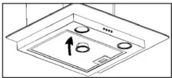
natural_image
Technical line drawing of a ceiling-mounted appliance with circular components and an upward arrow indicating direction (no text or symbols)B. 2W Kvadratno LED svetlo
1.B Uklonite Aluminijski filter

2.B Odvojite LED svetlo kako je prikazano i odspojite konektor napajanja LED svetla.
Priključite novo LED svetlo istog tipa i snage i vratite svetlo natrag u aspirator.

REŠAVANJE PROBLEMA
natural_image
Hand holding a power outlet switch with a cable, no text or symbols visiblenatural_image
Pure technical line drawing of a 3D geometric structure without any text, numbers, or symbolsnatural_image
Isometric line drawing of a brick wall with a small object on top, no text or symbols present
natural_image
Technical line drawing of a chimney mounted on a brick wall, showing structural details without any text or symbols.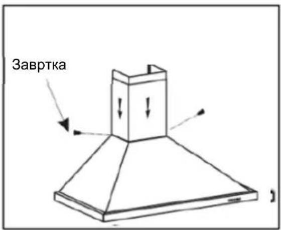
natural_image
Illustration showing two hand-drawn diagrams of a mechanical or architectural component, one with an arrow indicating direction and the other with a curved arrow (no text or symbols)natural_image
Four circular icons with different symbols: a fan, a leaf, a turbine, and a sun (no text or labels)Верзија 1
natural_image
Mechanical diagram showing two wheels mounted on a rail, with directional arrows indicating motion (no text or symbols)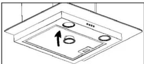
natural_image
Technical line drawing of a ceiling-mounted appliance with circular components and an upward arrow indicating motion (no text or symbols)natural_image
Diagram of airflow around a mechanical structure with directional arrows indicating movement (no text or symbols)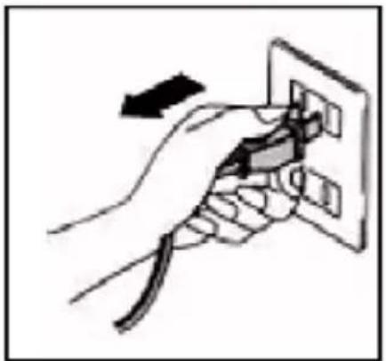
natural_image
Hand inserting a plug into an electrical outlet (no text or symbols visible)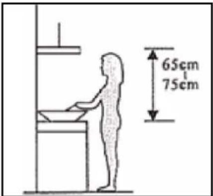
natural_image
Pure geometric diagram of a 3D curved surface with dashed lines and control points, no text or symbols presentnatural_image
Isometric line drawing of a brick wall with a cylindrical object inserted into it, no text or symbols present.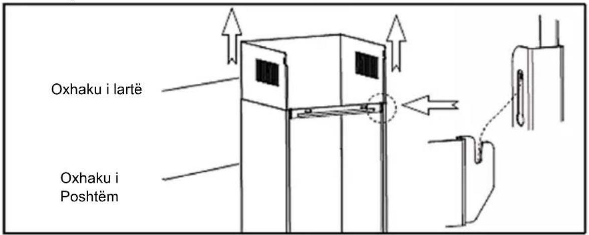
natural_image
Technical line drawing of a chimney mounted on a brick wall, showing structural details without any text or symbols.Instalimi (Ventilimi i brendshëm)
natural_image
Diagram of a mechanical or fluid system with directional arrows and a central block, no text or symbols present.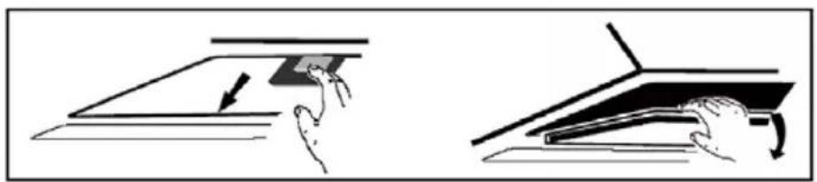
natural_image
Two-step diagram showing hand positioning of a mechanical component, one with an arrow indicating motion (no text or symbols)natural_image
Technical line drawing of a mechanical fan or motor with a close button and rotation arrow (no text or symbols on the diagram itself)Vërejtje:
natural_image
Five circular icons with different leaf and fan symbols, no text or labels presentVersioni 1
0 Butoni i fikjes (Off button)
natural_image
Mechanical diagram showing two wheels mounted on a rail, with directional arrows indicating motion (no text or symbols)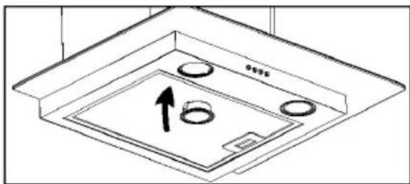
natural_image
Isometric line drawing of a ceiling structure with circular components and an upward arrow indicating direction (no text or symbols)natural_image
Diagram of airflow around a mechanical structure with directional arrows indicating movement (no text or symbols)natural_image
Hand holding a power outlet plug with a cable, no text or symbols visiblenatural_image
Pure geometric diagram of a 3D object with dashed lines and control points, no text or symbols present- Kuhinjsko napo obesite na kavelj za stenski nosilec.
natural_image
Isometric line drawing of a brick chimney mounted on a wall, with no text or symbols present.
natural_image
Architectural diagram of a brick chimney with upward arrows indicating airflow or ventilation (no text or symbols)- Spodnji dimnik pritrdite z 2 kosoma vijakov 4x8 mm.

natural_image
Diagram of a mechanical or fluid system with directional arrows and a central block, no text or symbols present.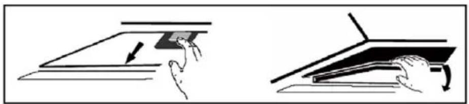
natural_image
Two-step diagram showing hand pressing a component on a flat surface, with no text or symbols present.V enoto vložite filter z aktivnim ogljem in ga obrnite v smeri urnega kazalca. Enako ponovite tudi na drugi strani.
Opomba:
natural_image
Technical line drawing of a mechanical fan or motor assembly with no visible text or symbolsnatural_image
Five circular icons with different leaf and sun symbols, no text or labels presentRazličica 1
0 Gumb za izklop
natural_image
Mechanical diagram showing two wheels mounted on a rail, with arrows indicating motion direction (no text or symbols)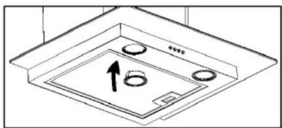
natural_image
Technical line drawing of a ceiling fixture with circular components and an upward arrow indicating direction (no text or symbols)Thank you for choosing this cooker hood.
This instruction manual is designed to provide you with all required instructions related to the installation, use and maintenance of the appliance.
In order to operate the unit correctly and safety, please read this instruction manual carefully before installation and usage.
The cooker hood use high quality materials, and is made with a streamlined design. Equipped with large power electricmotor and centrifugal fan, it also provides strong suction power, low noise operation, non-stick grease filter and easy assembly installation
It is important that you read these instructions before using your product and we strongly recommend that you keep them in a safe place for future reference.
WELCOME!
This device meets the highest standards, innovative technology and high comfort use.
Read these instructions carefully before using your new unit, and keep it carefully.
If you follow the instructions, your new appliances will provide you with many years of good service.
READ CAREFULLY THIS MANUAL AND KEEP THEM FOR FUTURE REFERENCE!
IF YOU SELL OR TRANSFER DEVICE TO OTHER PEOPLE, BE SURE TO INCLUDE THESE INSTRUCTIONS!
IMPORTANT SAFETY INSTRUCTIONS WARNING
The flash with the symbol of arrowhead, inside an equilateral triangle alerts the user about the presence of a dangerous tension not isolated inside the product which can be sufficiently powerful to constitute a risk of electrocution.
The point of exclamation inside an equilateral triangle alerts the user about the presence of important operating instructions and maintenance in the document enclosed in the package.

CAUTION

RISK OF ELECTRIC SHOCK DO NOT OPEN
Do not open the cover. In no case the user is allowed to operate inside the unit. Only a qualified technician from the manufacture is entitled to operate. By ignoring the safety instructions, the manufacturer cannot be hold responsible for the damage.
SAFETY PRECAUTIONS
- The appliance is not to be used by persons (including children) with reduced physical, sensory or mental capabilities or lack of experience and knowledge, unless they have been given supervision or instruction.
- Children being supervised not to play with the appliance.
- This appliance can be used by children aged 8 years and above and persons with reduced physical, sensory or mental capabilities, or lack of experience and knowledge, if they have been given supervision or instruction concerning use of the appliance in a safe way and understand the hazards involved.
- Children shall not play with the appliance.
- Cleaning and user maintenance shall not be mad by children without supervision.
-
There shall be adequate ventilation in the room when the range hood is used at the same time as appliances burning gas or other fuels (not applicable to appliances that only discharge air back to the room).
-
There is a fire risk if cleaning is not carried out in accordance with the instructions!
- Do not flame under the range hood
- CAUTION: Accessible parts may become hot when used with cooking appliances.
- The Air must not be discharged into a flue that is used for exhausting fumes from appliances brning gas or other fuels.
- When the range hood is located above gas appliance, this distance shell be at least 65cm
- Regulations concerning the discharge of air have to be fulfilled.
- If the supply cord is damaged, it must be replaced by the manufacturer, its service agent or similarly qualified persons in order to avoid a hazard.
- Never unplug the feed cable from the plug by tugging on the cable. Do not touch the feed cable with wet hands. Never move the appliance by pulling the cord and make sure the cord cannot become entangled.
- Always disconnect the appliance from the supply before assembling, disassembling or cleaning.
- The user must not leave the device unattended while it is in work.
- This appliance is only to be used for household purposes and only for the purpose it is made for.
- This appliance is intended for indoor use only
- The appliance is not intended to be operated by means of an external timer or a separate remote-control system. Your device must not be used connected to the same
power cable or fuse with another device.
- Only use the appropriate power connection and power socket for this device.
- Failure to maintain the appliance in a clean condition could lead to damage of the surface that could adversely affect the life of the appliance and possibly result in a hazardous situation. Such damages are not included in the warranty.
- WARNING: Switch off the appliance before changing accessories or approaching parts which move in use.
- Steam cleaner is not to be used.
- The use of accessory attachments, not recommended or sold by the appliance manufacturer, may cause hazards.
- Do not use appliance other than for its intended use.
Electrical connection
Make sure that the voltage (see name plate) and your home power supply match.
The mains plug should only be inserted into a correctly installed 220-240 V \~ 50 Hz socket.
No user-serviceable parts inside. Refer servicing to qualified service personnel.
Only plug this unit into a properly earthed outlet. If in doubt seek advice from a suitably qualified engineer.
Failure to follow these instructions can result in death, fire, or electrical shock.
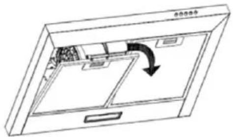
INSTALLATION
1. Prepare for installation
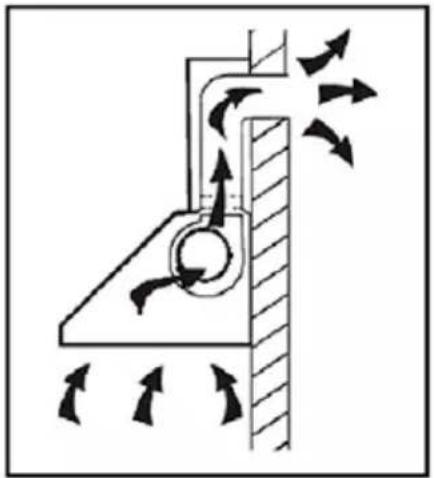
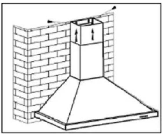
a. If you have an outlet to the outside, your cooker hood can be connected as below picture by means of an extraction duct (enamel, aluminum, flexible pipe or inflammable material with an interior diameter of 150mm).
b. Before installation, turn the unit off and unplug it from the outlet.
c. The cooker hood should be placed at a distance of 65\~75cm above the cooking plane for best effect.
natural_image
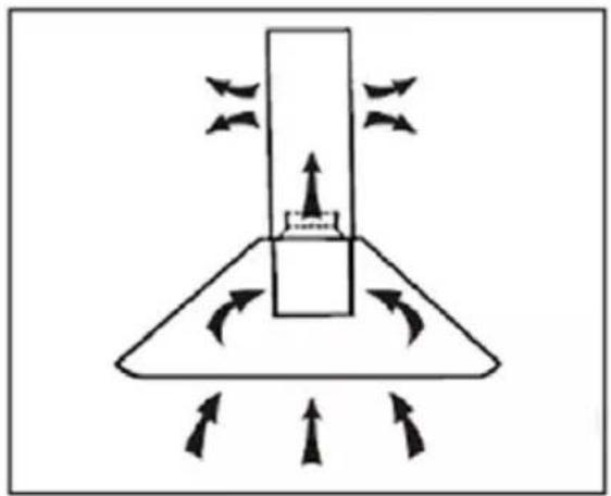
Diagram of airflow around a mechanical structure with directional arrows indicating movement (no text or symbols)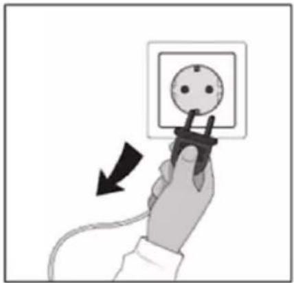
natural_image
Hand holding a plug inserted into an electrical socket, with a black arrow indicating the insertion direction (no text or symbols present)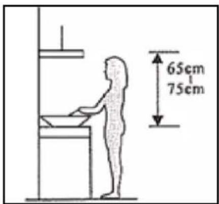
Attention! Observe the warning in the instruction sheet concerning the operation of the appliance when air is discharged from the room.
When the range hood and appliance supplied with energy other than electricity are simultaneously in operation, the negative pressure in the room must be not exceed 4 Pa (4×10⁻⁵ Bar)
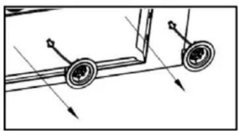
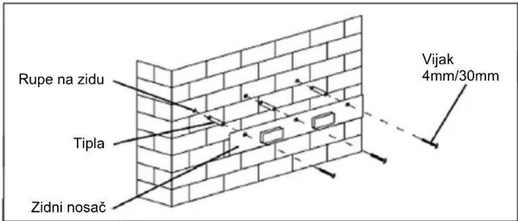
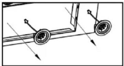
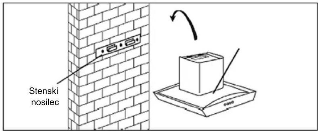
- Drill 3 x 8mm holes to accommodate the bracket. Screw and tighten the bracket onto the wall with the screws & screw plugs provided.
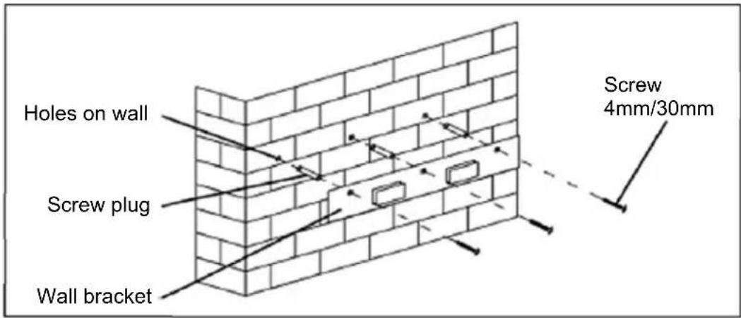
- For inclined panel Model, need to drill 4 x 8mm extra holes & fixing screws & screw plugs before installation.
natural_image
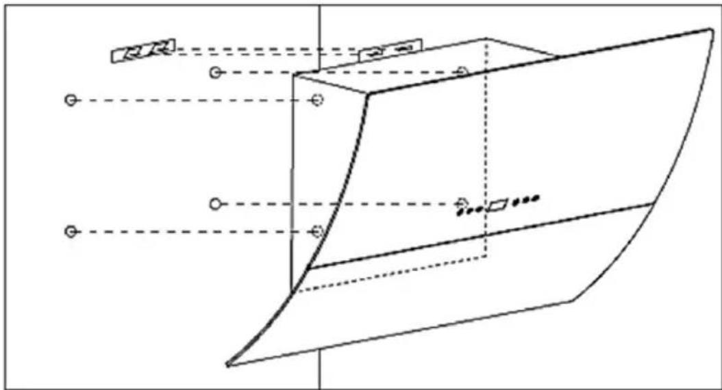
Pure geometric diagram of a 3D object with dashed lines and control points, no text or symbols present- Leave up the cooker hood and hang onto the wall bracket hook.

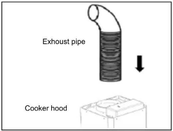
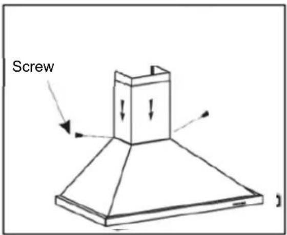
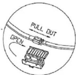
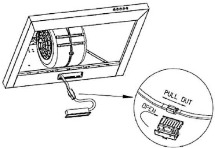
- Fix the one-way-valve to the air outlet of the cooker hood. Then, attached the exhaust pipe onto the one-way-valve as shown below.
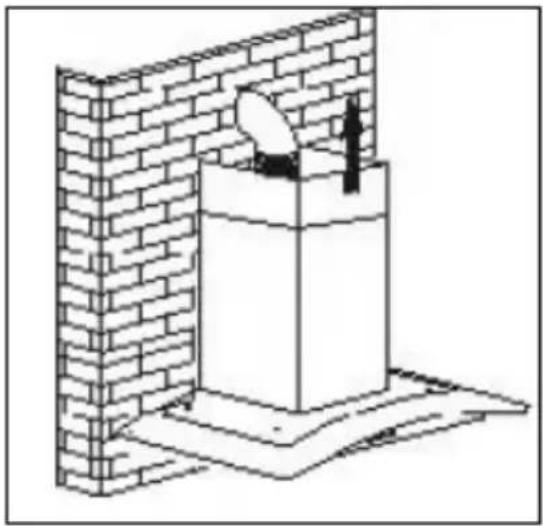
2. Chimney installation
2.a Glass model and T shape model
- By Put the upper chimney into lower chimney .Then pulling out the upper chimneyupwards. Adjustto reach the height required.
- Sliding the chimney to adjust the chimney height. When the height you required is reached, then hang the fixing hole to the fixing screws as showed in below pictures.
natural_image
Isometric line drawing of a brick chimney with a person standing on top, no text or symbols present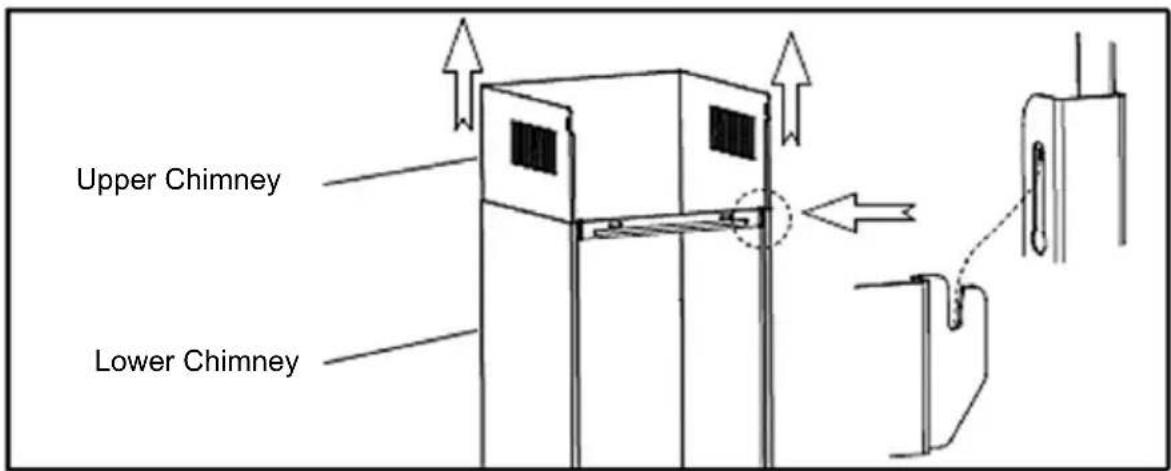
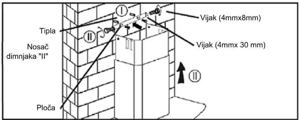
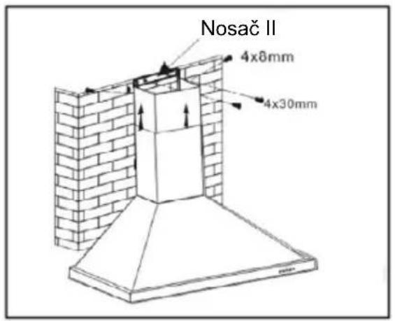
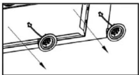
- Drill 2×8mm holes to accommodate the plate II. Screw and tighten the plate II onto the wall with 2 screws provided. Assembly the chimney onto the unit and fix it with 2 screws.
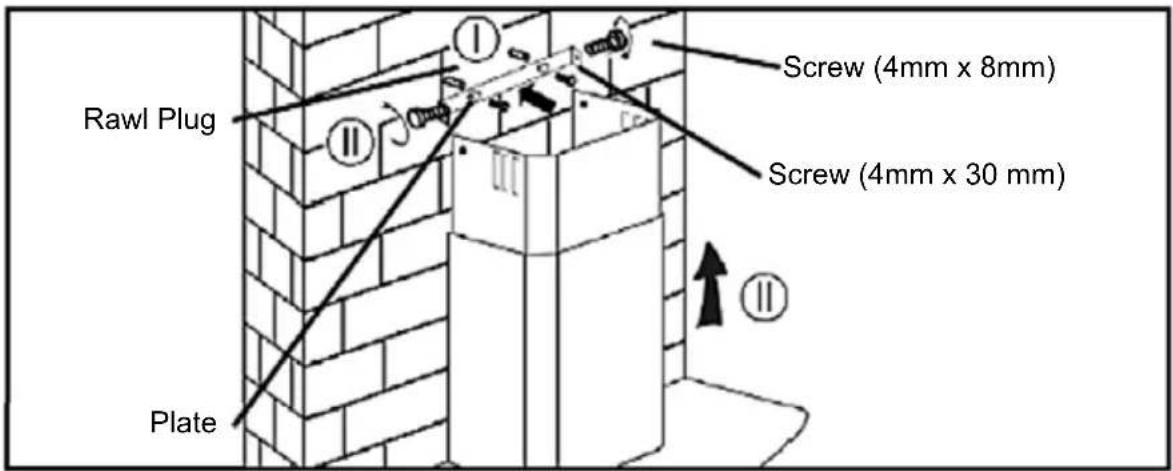
Warning: Failure to install the screws or fixing device in accordance with these instructions may result in electrical hazards.
2.b Tower model
- By Put the inner chimney into upper chimney. Then pulling out the upper chimneyupwards. Adjust to reach the height required.
natural_image
Technical line drawing of a brick chimney mounted on a wall, showing structural details without any text or symbols.- Fix the lower chimney with 2 pcs of 4x8mm screws.
- Sliding the chimney to adjust the chimney height. When the height you required is reached, then fix 2 pcs of 4x8mm screws onto the hole fixing with plate I as showed in below pictures

- Drill 2 x 8mm holes to accommodate the plate II. Screw and tighten the plate II onto the wall with 2 screws provided.
- Assembly the chimney onto the unit and fix it with 2 screws.
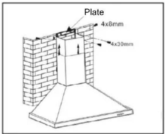
Warning: Failure to install the screws or fixing device in accordance with these instructions may result in electrical hazards.
Installation (Vent inside)
If you do not have an outlet to the outside, exhaust pipe is not required and the installation is similar to the one show in section "Installation (Vent outside)".
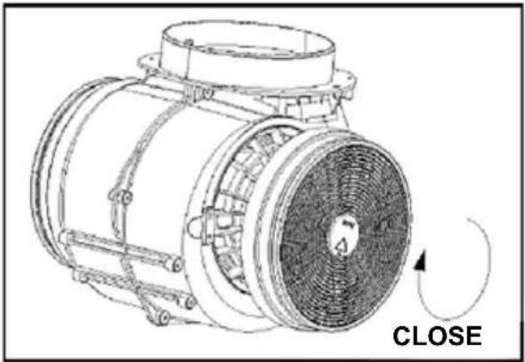
Activated carbon filter can be used to trap odors.
In order to install the activated carbon filter, the grease filter should be detached first. Press the lock and pull it downward.
natural_image
Diagram of a mechanical or fluid system with directional arrows indicating flow or movement (no text or symbols)
natural_image
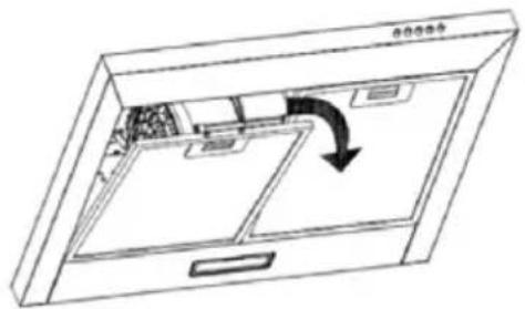
Two-step diagram showing a hand pressing down on a flat surface, with no text or symbols present.Plug the activated carbon filter into the unit and turn it in clockwise direction. Repeat the same on the other side.
Note:
- Carbon filter(s) are not included into Range Hood standard accessories. To purchase Carbon filter, please ask your dealer or service.
- Make sure the filter is securely locked. Otherwise, it would loosen and cause dangerous.
- When activated carbon filter attached, the suction power will be lower.
- The electrical connection must correspond to the electrical requirement noted on the rating plate, which is placed inside the cooker hood.
- The appliance should now be connected to the electrical supply.
- Check that the appliance is operating correctly by selecting each speed and switching the light bulbs on and off.
- Use a stainless steel cleaner and polish on the stainless steel sections of the appliance.
- If you are using the appliance in recirculation mode, then you should now fit the carbon filter.
natural_image
Technical line drawing of a mechanical component with a circular arrow indicating 'CLOSE' (no text or symbols on the diagram itself)OPERATION
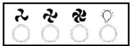
Mechanic/Electronic Push button

natural_image
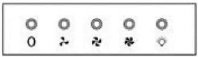
Four circular icons with different symbols: a propeller, a fan, a three-blade fan, and a sun-like light bulb (no text or labels)Version 1
0 Off button
It's used for turning off the fan.
Low Speed button
It's used for Ventilation on the kitchen. It is suitable for simmering and cooking which do not make much steam.
Medium Speed button
Airflow speed is ideally for ventilation in standard cooking operation.
High Speed button
When high density of smoke or steam produced, press high-speed button for highest effective ventilation.
Light button
NOTE: If Low / Medium/ High speed buttons are press at the same time, the unit will only operate at the highest speed
Touch control – Ver 1
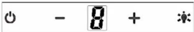
Off button
It's used for turning off the fan.
+ Speed plus button
For increasing the speed of the fan
- Speed decrease button
For decreasing the speed of the fan.
Light button
8 Digital display
Fan speed display:"1" for Low speed, "2" for Medium speed, "3" for High speed.
Quick timer: Press "+" & "-" hold for 1 second, Digital display will flashing & into 5 minutes count down, after 5 minutes motor & light will turn off automatic & Buzzer sound for 1 second.
MAINTENANCE
Before any maintenance or start to cleaning switch the unit off and disconnect unit from mian supply!
Regular Cleaning
Use a soft cloth moistened with hand-warm mildly soapy water or household cleaning detergent. Never use metal pads, chemical, abrasive material or stiff brush to clean the unit.
Grease Filter Monthly Cleaning
WARNING: Clean the filter every month to prevent any risk of fire.
The filter collects grease, smoke and dust.
The filter is directly connected with efficiency of the cooker hood. If not cleaned, the grease residue (potential flammable) will saturate on the filter. Clean it with household cleaning detergent.
Annual Cleaning for Activated Carbon Filter
Apply to unit that installed internal air circulation (not vented to the outside).
This filter traps odours and must be replaced at least once a year depending on how frequent the cooker hood used.
To prurchase a new Carbon Filter, contact your dealer or Service centre.
Light Bulb replacement
WARNING
If the supply LED bulb is damaged, it must be replaced by the manufacturer, its service agent or similarly qualified persons in order to avoid a hazard.
-
Switch the unit Off and unplug the appliance from mains supply.
-
Remove the LED lamp according to different type on the hood:
A. Round LED Lamp (1,5W i 2W)
1.A Remove the Aluminium Filter
2.A Unplug the LED lamp cable as shown on drawing
3A Take out the whole LED light from the panel and replace the same type and rated LED light
natural_image
Mechanical diagram showing two wheels mounted on a frame with directional arrows indicating motion (no text or symbols)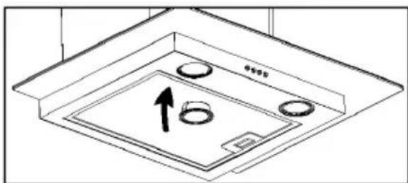
natural_image
Technical line drawing of a ceiling-mounted appliance with circular components and an upward arrow indicating direction (no text or symbols)B. 2W rectangle LED
1.B Remove the Aluminium Filter
2.B Unplug the LED lamp cable as below drawing and take out the whole LED light from the panel and replace the same type and rated LED light
TROUBLESHOOTING
The following simple issues can be handled by the user. Please call the after-sale service department if the issues are not settled!
| Problem Possible cause | Solution | |
| Light on, but fan does not work | The fan blade is jammed | Switch of the unit and repair by The motor is damaged. qualified service personnel only |
| The motor is damaged | ||
| Both light and fan do not work | The light bulb burned | Replace the bulb with correct rating |
| Power cord looses | Plug in to the power supply again. | |
| Serious Vibration of the unit | The fan blade is damaged. | Switch of the unit and repair by qualified service personnel only. |
| The fan motor is not fixed tightly. | Switch of the unit and repair by qualified service personnel only | |
| The unit is not hung properly on the bracket | Take down the unit and check whether the bracket is in proper location. | |
| Suction performance not good | Too long distance between the unit and the cooking plane | Readjust the distance to 65-75cm |
TRANSPORT AND SERVICE
WARNING: Handling and transportation. It is required to perform transportation of device in its own original box. Metal, Plastic or Glass parts may be broken during Incorrect packaging. Its electrical parts may be damaged.
Unplug It while It is operating for transport, maintenance or repair purposes.
DISPOSAL OF ELECTRICAL AND ELECTRONIC EQUIPMENT
To protect our environment and to recycle the raw materials used as completely as possible, the consumer is asked to return unserviceable equipment to the public collection system for electrical and electronic.
The symbol of the crossed indicates that this product must be returned to the collection point for electronic waste to feed it by recycling the best possible raw material recycling.
By ensuring this product you will prevent possible negative effects on the environment and human health, which could otherwise be caused due to improper disposal of that product. The recycling of materials from this product, you will help to preserve a healthy environment and natural resources.
For detailed information about the collection of EE products contact the dealer where you purchased the product.
EU DECLARATON OF CONFORMITY
This device is manufactured in accordance with the applicable European standards and in accordance with all applicable Directives and Regulations.
EU declaration of conformity can be downloaded from the following link: www.msan.hr/dokumentacijaartikala
JAMSTVENI LIST HR
VIVAX
MODEL UREĐAJA
SERIJSKI BROJ
DATUM PRODAJE
BROJ RAČUNA PRODAVATELJA
POTPIS I PEČAT PRODAVATELJA
POTPIS I PEČAT PRODAVATELJA
GARANCIJSKA IZJAVA
- Ovom garancijom garantira proizvođač proizvoda, preko KIM TEC d.o.o., kao uvoznika i davatelja garancije u Bosni i Hercegovini besplatan popravak istog u skladu s važećim propisima i u skladu s uvjetima opisanim u ovom garantnom listu. Ovom garancijom garantiramo da će predmet ove garancije raditi bez greške uzrokovane eventualnom lošom izradom i lošim materijalom izrade. Svi eventualno nastali kvarovi biti će besplatno otklonjeni u ovlaštenom servisu u garantnom roku.
- UVJETI GARANCIJE: Garantni rok počinje teći od dana kupnje proizvoda i traje:
| 60 MJESECI (5 godina) | HLADNJACI,VERTIKALNE I HORIZONTALNE ŠKRINJE |
| 36 MJESECI (3 godine) | ŠTEDNJACI, PERILICE I SUŠILICE RUBLJA, PERILICESUĐA, KUHINJSKE NAPE, UGRADBENE PEĆNICE IPLOČE, GRIJALICE VODE |
- U slučaju kvara na proizvodu koji je predmet ove garancije, obavezujemo se da ćemo isti popraviti u najkraćem mogućem roku, a najkasnije u roku od 45 dana. Ako se proizvod ne može popraviti ili se ne popravi u roku od 45 dana, biti će zamijenjen novim.
- Garancija se priznaje samo uz račun o kupnji, te uz ovaj garantni list koji mora biti ispravno popunjen odnosno mora sadržavati datum prodaje, pečat i potpis prodavatelja.
- Davalac garancije osigurava servis i rezervne dijelove 7 godina od datuma kupnje.