
Onego - Bike trainer Spokey - Free user manual and instructions
Find the device manual for free Onego Spokey in PDF.


| Product Type | Magnetic bike trainer |
| Brand | Spokey |
| Model | Onego / Onego+ |
| Dimensions (assembled) | 89 x 40.5 x 98 cm |
| Maximum User Weight | 100 kg |
| Power Supply | 2 x 1.5V AAA batteries (not included) |
| Resistance Type | Manual magnetic resistance |
| Resistance Levels | 8 levels |
| Display Functions | Time, Speed, Distance, Calories |
| Assembly Required | Yes (7 steps, tools included) |
| Intended Use | Home use only |
| Safety Features | Heart rate monitoring (may be inaccurate); immediate stop if feeling faint |
| Maintenance | Wipe with damp cloth; store in dry place; check bolts regularly |
| Included Parts | Main frame, front/rear stabilizers, front post, handlebar, seat, seat post, pedals, computer, hardware, tension knob, sensor wires, etc. (full list in manual) |
| Spare Parts | 26 numbered parts listed in manual |
| Repairability | Repairs only by qualified SPOKEY employee |
| Computer Battery | 2 x AAA (1.5V) |
| Pedal Type | Standard left/right pedals with toe straps |
| Saddle Adjustment | Vertical height adjustable via knob |
| Leveling | Adjustable rear stabilizer end caps |
Frequently Asked Questions - Onego Spokey
User questions about Onego Spokey
0 question about this device. Answer the ones you know or ask your own.
Ask a new question about this device
Download the instructions for your Bike trainer in PDF format for free! Find your manual Onego - Spokey and take your electronic device back in hand. On this page are published all the documents necessary for the use of your device. Onego by Spokey.
USER MANUAL Onego Spokey
926190 / 926201 / 926210 / 926211
MODEL: ONEGO / ONEGO+
(SCHEMAT / DIAGRAM / CXEMA / SCHÉMA / SCHEMA / SHÊMA 1
PL) ROWER MAGNETYCZNY 1 1
(EN) MAGNETIC BIKE 14
(RU) МАГНЕТИЧЕСКИЙ ВЕЛОТРЕНАЖЕР 17
(CZ) MAGNETICKÝ ROTOPED 20
(SK) MAGNETICKÝ BICYKEL 23
(LT) MAGNETINIS DVIRATIS 26
(LV) MAGNĚTISKS VELOTRENAŽIERIS 29
(DE) HEIMTRAINER 32
Specyfikacje tego produktu mogą się nieco różnić od ilustracji, bądź ulec zmianie. / The specifications of this product may slightly differ from the illustrations or may be modified. / Спецификации данного изделия могут несколько отличаться от иллюстраций или в них могут быть внесены изменения. / Specifikace tohoto produktu se mohou lišit od ilustrace nebo mohou být změněny. / Špecifikácia tohto produktu sa môže minimálne lišit od uvedenej na obrázku alebo podľahnút úpravám / Šio produkto specifikacijos gali šiek tiek skirtis nuo parodytu, arba pasikeisti. / Šī produkta specifikácijas var mazliet atškirties no šeit parādītajām, vai mainīties. / Die Eigenschaften des Produkts können von den Abbildungen abweichen oder einer Änderung unterliegen.

1
KROK | STEP | WAF | ZINGSNIS | SOLIS | SCHRITT


No.8 Qty 4 No.9 Qty 4

No.10 Qty 4

2
KROK | STEP | WAF | ZINGSNIS | SOLIS | SCHRITT



5,6
KROK | STEP | WAR | ZINGENSIS | SOLIS | SCHRITT
7
KROK | STEP | UAR | ZINGSINS | SOLIS | SCHRITT
PRZENOSZENIE URZĄDZENIA | MOVING THE DEVICE | ПЕРЕНОС УСТРОЙСТВА | PŘENÁŠENÍ ZAŘÍZENÍ | PRENÁŠANIE ZARIADENIA | IRENGINIO PERKÉLIMAS | KITĄ VIETĄ | IERÍCES PĂRVIETOŠANA | TRANSPORT


POZIOMOWANIE URZADZENIA | LEVELLING | ГОРИЗОНТАЛЬНОЕ РАЗМЕЩЕНИЕ УСТРОЙСТВА | KALIBRACE ZAÑIZENÍ | VODOROVNÁ POLOHA ZARIADENIA | PRIETAISO HORIZONTALUMO NUSTATYMAS | IERICES HORIZONTÁLA NOVIETOŠANA | NIVELLIERUNG DES GERÄTES

(PL) Zaślepki tylnego stabilizatora
(EN) Rear Stabilizer End Cap
(RU) Заглушки заднего стабилизатора
(CZ) Záslepky zadního stabilizátoru
(SK) Záslepky zadného stabilizátora
(LT) Užpakalinio stabilizatoriaus aklės
(LV) Pakalējā stabilizatora tapas
(DE) Endkappen am hinteren Stabilisator
REGULACJA SIODEŁKA | ADJUSTMENT OF THE BIKE SADDLE | PEGYLIROVKA CEDLA | NASTAVENÍ SEDLA | NASTAVENIE SEDADLA | SÉDYNÈS REGULIAVIMAS | SÉDEKŁA REGULÉŠANA | EINSTELLUNG SATTEL

(PL) Gałka do regulacji
(EN) Knob
(RU) Ручка для регулировки
(CZ) Knoflik pro regulace
(SK) Kluka na regulovanie
(LT) Reguliavimo rankutė
(LV) Regulēšanas rokturis
(DE) Drehknopf zur Einstellung
MONTAŻ, USTAWIANIE I KONSERWACJA
ZESTAWIENIE CZEŚCI
ASSEMBLY, SETUP AND MAINTENANCE
LIST OF PARTS
| NO. | Description | QTY | NO. | Description | QTY |
| 01 | Main Frame | 1 | 14 | Tension Control Knob | 1 |
| 02 | Front Stabilizer | 1 | 15 | Inner Hex Bolt(M8X30) | 2 |
| 03 | Rear Stabilizer | 1 | 16 | Washer(1/2") | 2 |
| 04 | Front Post | 1 | 17 | Computer | 1 |
| 05 | Handlebar | 1 | 18 | Nut | 3 |
| 06 | Seat Post | 1 | 19 | Washer | 3 |
| 07 | Seat | 1 | 20 | Pedal (L/R) | 1set |
| 08 | Carriage Bolt (M8X60) | 4 | 21 | Lower Sensor Wire | 1 |
| 09 | Curved Washer | 8 | 22 | Wire C | 1 |
| 10 | Domed Nut(M8) | 4 | 23 | Crank | 1 |
| 11 | Fixing Knob | 1 | 24 | Lower Tension Hook | 1 |
| 12 | Inner Hex Bolt (M8x15) | 4 | 25 | Upper Tension Cable | 1 |
| 13 | Screw (M5x10) | 1 | 26 | Upper Sensor Wire | 1 |
СБОРКА, НАСТРОЙКА И УХОД ЗА ТРЕНАЖЕРОМ
ПЕРЕЧЕНЬ ЭЛЕМЕНТОВ
Dimensions of the assembled exercise machine - 89 x 40,5 x 98cm
Maximum weight of the user - 100 kg
The equipment is designed for full body exercise
SAFETY REMARKS
- Prior to the assembly of the device and training, read carefully this instruction manual. Safe and effective use of the device can be guaranteed only if it is assembled, maintained, and used appropriately, in a manner described in the manual. If you are not the user, please provide all the users with this instruction and inform them about all possible hazards and precautions.
- Prior to starting with any exercises, please consult a doctor in order to make sure that there are no mental or physical conditions that could be harmful to your health and safety. The consultancy with a doctor may also protect you against an inappropriate use of the device. A doctor will specify whether taking drugs that would have an effect on pulse, pressure or cholesterol level is justified.
- Pay attention to your body signals. Inappropriate or excessive training may have a negative influence on your health. Immediately stop exercising if any of the following symptoms occurs: pain, chest constriction, irregular pulse, exceptional shortness of breath, faints, vertigo, nausea. If any of the above symptoms occurs, contact your doctor immediately and give up training until then.
- Children and animals should be kept away from the device. The device is intended only and exclusively for adults.
- The device should be placed on a straight, stable and tough surface, protected with a mat or a carpet. For the sake of safety, 2 m of free space, needed for a safe usage, should be left to each side around the device. Prior to starting any exercises, make sure that all the bolts and nuts are tightly fitted. Please, pay special attention to the parts that are prone to wearing out the most.
- An appropriate safety level of this device may by guaranteed only if it is subject to regular service and inspection.
- The device should be always used in accordance with its purpose. Should during the assembly or use any of the parts appear to be faulty
or make alarming sounds, stop using the exerciser and have it serviced. You must not use a damaged device.
- During training, wear appropriate clothes. Avoid loose clothes that could get caught in the device or such that could restrict or even make movement impossible. It is also advised to exercise in appropriate sport shoes. At the beginning, set a slow pace. During exercises, hold handgrips and do not leave the saddle.
- The bicycle is intended for home use. Maximum allowed user's body weight amounts to 100 kg.
- Take special precautions while lifting and moving the device. The device should be always moved by two persons. While lifting or moving the equipment, maintain an appropriate posture so as to avoid backbone damage.
- The equipment was counted among class H and C and is intended for home use exclusively. It cannot be used as a therapeutic or rehabilitation equipment.
- While assembling the device, strictly follow the enclosed instruction and use only the parts included in the set. Prior to the assembly, check whether the set contains all the parts that the enclosed list includes.
- It is advised against leaving control devices, which could restrict movement, in such a position that any of the elements sticks out. Warning: prior to starting a training on this device, read the instruction manual carefully. we do not hold responsibility for injuries or damages to objects caused by an inappropriate use of this product. Body injuries may happen due to an inappropriate or too intensive training
WARNING! Heart rate monitoring system May be inaccurate. Over exercising May result In serious injury Or death. If you feel faint stop exercising immediately.
Health injury may result from the incorrect or too intensive training.
PREPARATIONS
- Before assembly make sure there is enough space.
- Use the recommended tools.
- Before assembly check if there are all the parts in the box.
It is recommended that product should be assembled by at least two people to avoid injuries.
Most of the assembly equipment listed here has been packed separately, but some elements come preassembled in certain assembly parts. If it is required, disassemble them and assemble again.
Read the instructions of all assembly steps and familiarize with all the devices installed.
ASSEMBLY INSTRUCTIONS (Drawings - p. 2-4)
Note: Follow the assembly instructions below:
STEP 1
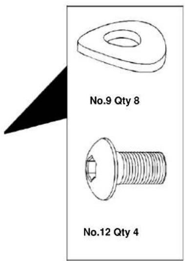
Attach the Front Stabilizer (2) to the Main Frame (1) using 2pcs of Domed Nuts (10), Curved Washers (9) and Carriage Bolts (8). The installation of the Rear Stabilizer (3) is same to the Front Stabilizer (2).
STEP 2
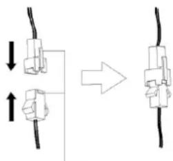
Connected Lower Tension hook(24) and Upper Tension Cable (25) as picture A. Connected lower Sensor Wire(21) and Upper Sensor Wire(26) as picture (OneGo +). Attach the Front Post (4) to the Main Frame (1) using 4pcs of Inner Hex Bolts
(12) and Curved Washers (9)..
STEP 3
Please first turn the tension to the minimum section “—”. Then fix the Tension Control Knob (14) to the Front Post (4) with a Screws (13).
STEP 4
Attach the Handlebar (5) to the Front Post (4) using 2pcs of Inner Hex Bolt (15), 2pcs of Washer(16). Then connect the Lower Sensor Wire (21) and Upper Sensor Wire (22). Insert computer (17) in the computer holder carefully on the Front Post (4). These two parts need to be in the same side when connect. (8) in the opening in the saddle column base on the main frame (1) clockwise. Tighten to fix the saddle column in selected position.
STEP 5
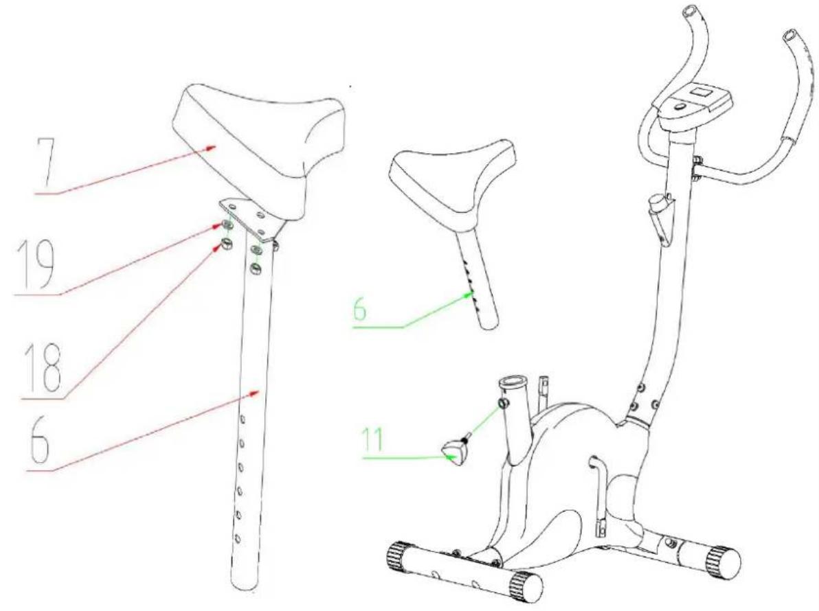
Fixing the Seat (7) on Seat Post (6) with 3pcs of Washers (19, and Nut (18) tightly
STEP 6.
Insert the Seat Post (6) into the Main Frame
(1) and line up the holes that give the correct seat height. (This can be done after it has been assembled.) Secure the seat in position with the Fixing Knob (11)
STEP 7
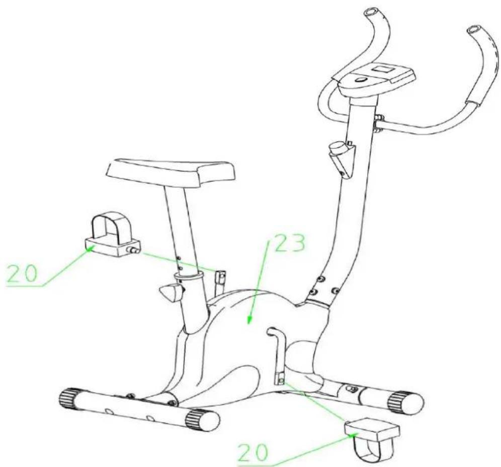
Fixing left pedal (20) on the left side of crank (23), fixing right pedal (20) on the right side of crank (23), make sure it is tightly.
STEP 8 (for OneGo+ only).
Connect the expanders (27) to the hooks on the front stabilizer (2).
Levelling and Moving the device (pictures p. 5-7)
Before you start exercising, it is recommended to verify whether the bike is positioned correctly. Please level the equipment by means of the stabilizer knobs
To transport the device, raise it carefully and move to another place, holding it on both sides.
Height adjustment of the bike saddle (drawing - p.4)
Turn the Saddle adjustment knob (11) counter clockwise to loosen the saddle in the column (6). Then, eject the saddle column slowly from the base or insert it slowly to choose the required position of the saddle. Fix the saddle in the required position tightening the saddle column adjustment knob (11) clockwise.
ATTENTION: While adjusting the height of the saddle, make sure that the plastic sleeve does not exceed the level marked by the line on the saddle post..
Resistance adjustment
The Resistance adjustment function allows to change resistance on the pedals. High resistance requires larger effort while pedalling, whereas the low one decreases the effort. Force of resistance is regulated by a knob placed on the handlebar post. In order to decrease resistance, adjustment
knob should be turned towards the "1" number whereas so as to increase resistance, the knob should be turned towards the "8" number. In order to achieve a satisfying effect, resistance level should be set during a training.
MAINTENANCE
- Prior to each use of the bicycle, make sure that all the bolts, nuts and knobs are tightly fitting.
- Aggressive cleaning products must not be used to clean the device. Use a soft, damp cloth to remove dirt and dust. Clean sweat traces since acidic pH may damage the upholstery.
- The device should be kept in a dry place in order to protect it against dampness and corrosion.
- Should the computer work incorrectly, make sure that all the cables are connected appropriately, especially the upper cable with the computer. If the computer still does not work, make sure that batteries have been put in appropriately and that they are not worn-out. If the readout on the display screen is not legible or some elements are invisible, replace
batteries immediately.
- In case of no resistance adjustment, make sure that the upper sensor cable is well connected with the lower cable. CAUTION: Due to the protection of the natural environment, worn-out batteries, power adapters, motors etc. should not be disposed with household wastes. Worn-out batteries, power adapters, motors etc. should be taken to a point that will utilise them in agreement with the enforceable law on environmental protection. It is recommended to check the power cord and the plug periodically. Never pull the cord. In case of damage, the device should not be used. Never repair the device on your own. Repairs should be made by a qualified SPOKEY's company employee.
HOW TO OPERATE THE BIKE METER
POWER SUPPLY
Batteries: 1.5V AAA (2 pieces), not supplied with the bicycle
Inserting batteries
- Insert two batteries at the back of the counter.
- Make sure that the batteries are correctly positioned.
- If the display is unreadable or only some segments are visible, remove
the batteries and re-insert them.
- After removing the batteries, all function values will be reset.
COUNTER
First start-up
Before the first start-up, make sure that all the cables have been connected correctly and that the batteries have been inserted correctly. The display will turn on once you press the button or when you start pedaling.
Auto on-off
After 4 minutes, the meter enters the energy saving mode. All settings and data are kept until restarting the meter. In case the screen does not start, disconnect power supply and wait for 15 seconds.
Resetting
To reset all values, keep the MODE button pressed for 3 seconds. Note: Values will also be reset when the battery is removed from the gauge.
Device error
If an incorrect reading appears on the counter, remove the batteries and reinsert them.
Button
MODE selecting the counter functions
Functions
TIME(TMR): counts the time of the current training session.
SPEED(SPD): displays the current speed.
DISTANCE(DST): counts the distance of the current training session.
CALORIES(CAL): counts the calories burnt during the current training session.
THE SCOPE OF MEASUREMENT
TIME: 00:00-99:59 MIN/SEC
SPEED: 0.0-999.9ML/H
DISTANCE: 0.00-9999ML
CALORIE:0.0-9999 CAL
SOLVING PROBLEMS
Problem: The display does not work
Solution: 1. Dismantle the counter and check if all cables are properly connected.
2. Check if batteries have been inserted correctly
3. The batteries might be used up. Try using new batteries.
Problem: The bike is wobbling during exercise
Solution: Use the rear stabiliser plugs to properly level the device.
Problem: Squeaks or creaking can are heard during workout.
Solution: The bolts might be loosened. Check all bolts carefully and, if necessary, tighten them using the keys included in the kit.
USAGE AND TRAINING
Your body position

Sit on the saddle, put your feet in the pedals so that they are blocked between the pedal base and the protective belt, put your hands on the handlebar. During exercises, keep your back straight (see the drawing).
TRAINING MANUAL
Adherence to the following TRAINING CYCLE will bring
many benefits to your health, such as physical fitness, muscle development and weight loss - in conjunction with the calorie intake control.
Exercises with the use of stationary bicycle can replace exercises done with the use of an ordinary bicycle.

Refers to the meter
The equipment label depicting a crossed-out wheeled bin symbol informs that it is forbidden to dispose of waste electrical and electronic equipment together with other types of waste. In accordance with the WEE directive on waste electrical and electronic equipment, separate waste management processes should be applied for this type of equipment. The user who intends to dispose of such a product is obliged to return it to an electronic equipment collection point thanks to which they can contribute to its re-use, recycling, and recovery and, in this way, protect the environment. To do this, contact the sales point where the equipment was purchased or a representative of the local authorities. Hazardous substances included in electronic equipment can have negative long-term influence on the natural environment and they can also have negative effect on human health.
ШАГ 4 Монтаж колонки седла
KROK 8 (pre model OneGo +)
Pripevnite expandéry k hákom na prednom stabilizátoru.
6 ŽINGSNIS.
6 SOLIS
SCHRITT 5

- MODEL: ONEGO / ONEGO
- 5,6
- 7
- MONTAŻ, USTAWIANIE I KONSERWACJA
- ASSEMBLY, SETUP AND MAINTENANCE
- СБОРКА, НАСТРОЙКА И УХОД ЗА ТРЕНАЖЕРОМ
- SAFETY REMARKS
- PREPARATIONS
- ASSEMBLY INSTRUCTIONS (DRAWINGS - P. 2-4)
- STEP 1
- STEP 2
- STEP 3
- STEP 4
- STEP 5
- STEP 6
- STEP 7
- LEVELLING AND MOVING THE DEVICE (PICTURES P. 5-7)
- HEIGHT ADJUSTMENT OF THE BIKE SADDLE (DRAWING - P.4)
- RESISTANCE ADJUSTMENT
- MAINTENANCE
- HOW TO OPERATE THE BIKE METER
- POWER SUPPLY
- INSERTING BATTERIES
- COUNTER
- FIRST START-UP
- AUTO ON-OFF
- RESETTING
- DEVICE ERROR
- BUTTON
- FUNCTIONS
- THE SCOPE OF MEASUREMENT
- SOLVING PROBLEMS
- PROBLEM: THE DISPLAY DOES NOT WORK
- USAGE AND TRAINING
- YOUR BODY POSITION
- TRAINING MANUAL
- REFERS TO THE METER
- ШАГ 4 МОНТАЖ КОЛОНКИ СЕДЛА
- KROK 8 (PRE MODEL ONEGO +)
- 6 ŽINGSNIS
- 6 SOLIS
- SCHRITT 5
Brand : Spokey
Model : Onego
Category : Bike trainer