
D13VH - Drill HiKOKI - Free user manual and instructions
Find the device manual for free D13VH HiKOKI in PDF.


| Product Type | Hammer Drill |
| Brand | HiKOKI |
| Model | D13VH |
| Chuck Capacity | 13 mm (1/2 in) |
| Power Source | Corded Electric |
| Input Power | 700 W |
| No-Load Speed | 0-2800 RPM (variable) |
| Impact Rate | 0-44800 BPM |
| Drilling Capacity (Steel) | 13 mm |
| Drilling Capacity (Wood) | 40 mm |
| Drilling Capacity (Concrete) | 16 mm |
| Weight | 1.9 kg (4.2 lbs) |
| Dimensions (L x W x H) | 280 x 70 x 220 mm |
| Vibration Level (Drilling) | 8.5 m/s² |
| Sound Pressure Level | 92 dB(A) |
| Key Functions | Variable speed trigger, forward/reverse rotation, hammer drilling mode, depth gauge |
| Maintenance & Cleaning | Brush inspection every 50 hours, clean ventilation slots regularly |
| Safety Features | Lock-on button, double insulation, safety switch |
| Spare Parts & Repairability | Carbon brushes, chuck, switch, armature available |
| General Information | Includes auxiliary handle, depth stop, and carrying case |
Frequently Asked Questions - D13VH HiKOKI
User questions about D13VH HiKOKI
0 question about this device. Answer the ones you know or ask your own.
Ask a new question about this device
Download the instructions for your Drill in PDF format for free! Find your manual D13VH - HiKOKI and take your electronic device back in hand. On this page are published all the documents necessary for the use of your device. D13VH by HiKOKI.
USER MANUAL D13VH HiKOKI
natural_image
Technical line drawing of a drill bit with handle and screwdriver (no text or labels)Read through carefully and understand these instructions before use.
2
3
4
5
6
7
8
9
10
| English Deutsch Ελληνικά Polski | ||||
| 1 | Drill chuck Bohrfutter Σφικτήρας δραπάνου Uchwyt wiertarski | |||
| 2 | Chuck wrench Futterschlüssel Κλειδί σφικτήρα | Klucz do uchwytu wiertarskiego | ||
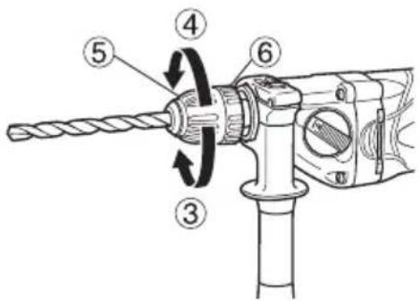
| 3 | Tighten Anziehen Σφίξτε Dokręcanie | |||
| 4 | Loosen Lösen Χαλαρώστε Luzowanie | |||
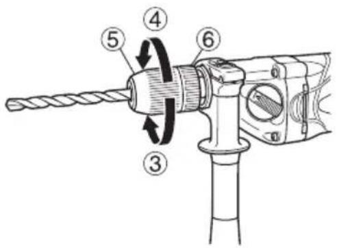
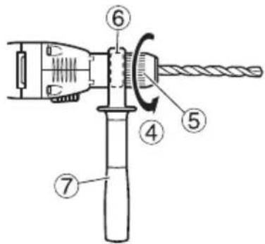
| 5 | Sleeve Manschette Συνδετικός δακτύλιος Tuleja | |||
| 6 | Retaining ring | Haltering | Δακτύλιος συγκράτησης | Pierścień ustalający |
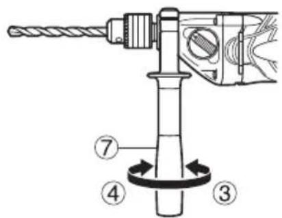
| 7 | Side handle | Seitengriff | Πλευρική λαβή | Uchwyt boczny |
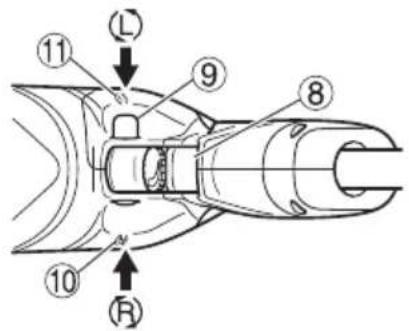
| 8 | Switch trigger | Abzugschalter | Σκανδάλη διακόπτης | Spust włącznika |
| 9 | Push button | Druckknopf | Κουμπί ώθησης | Przycisk |
| 10 | (R) mark | Markierung (R) | (R) σημάδι Symbol | (R) |
| 11 | (L) mark | Markierung (L) | (L) σημάδι | Symbol (L) |
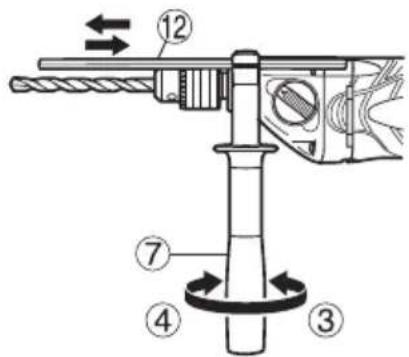
| 12 | Depth gauge | Tiefenlehre | Μετρητής βάθους | Ogranicznik głębokości |
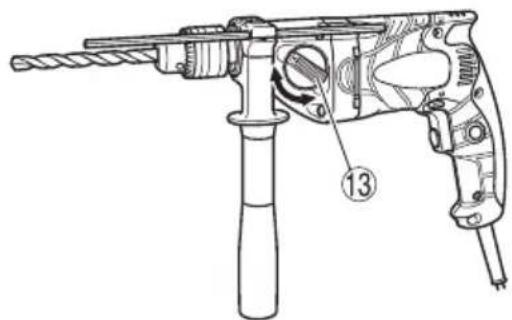
| 13 | Gear shift dial Gangschaltscheibe | Καντράν αλλαγής ταχύτητας | Pokrętło zmiany przełożenia | |
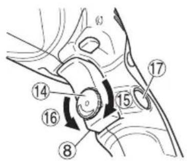
| 14 | Speed control dial | Drehzahlskala | Καντράν ελέγχου ταχύτητας | Pokrętło kontroli prędkości |
| 15 | High speed | Hohe Drehzahl | Υψηλή ταχύτητα | Duża prędkość |
| 16 | Low speed | Niedrige Drehzahl | Χαμηλή ταχύτητα | Mała prędkość |
| 17 | Stopper | Stopper | Στόπερ Zatyczka | |
| Magyar Čeština Türkçe | |||
| 1 | Fúrótokmány | Sklíčidlo | Matkap mandreni |
| 2 | Tokmánykulcs | Klíč sklíčidla | Mandren anahtarı |
| 3 | Megszorítani | Utažení | Sıkıştırma |
| 4 | Kiengedni | Povolení | Gevşetme |
| 5 | Karmantyú | Objímka | Manşon |
| 6 | Visszatartó gyűrű | Zádržný kroužek | Tutucu halka |
| 7 | Oldalfogantyú | Boční držadlo Yan kol | |
| 8 | Kapcsoló Spoušť | Anahtar tetiği | |
| 9 | Nyomógomb | Tlačítko | İtme düğmesi |
| 10 | (R) - jobbra forgásirány-jelölés | Znak pravého chodu (R) | (R) işareti |
| 11 | (L) - jobbra forgásirány-jelölés | Znak levého chodu (L) | (L) işareti |
| 12 | Mélységmérő | Měřítko hloubky | Derinlik ölçme aleti |
| 13 | Fordulatszám kapcsoló | Číselník převodovky | Vites değiştirme düğmesi |
| 14 | Fordulatszám szabályzó | Číselník volby rychlosti | Hız kontrol düğmesi |
| 15 | Magas fordulatszám | Vysoká rychlost | Yüksek hız |
| 16 | Alacsony fordulatszám | Nízká rychlost | Düşük hız |
| 17 | Ütköző | Zarážka | Derinlik mesnedi |
| Symbols⚠ WARNINGThe following show symbols used for the machine. Be sure that you understand their meaning before use. | Symbole⚠ WARNINGDie folgenden Symbole werden für diese Maschine verwendet. Achten Sie darauf, diese vor der Verwendung zu verstehen. | Σύμβολα⚠ ΠΡΟΕΙΔΟΠΟΙΗΣΗΤα παρακάτω δείχνουν τα σύμβολα που χρησιμοποιούνται στο μηχάνημα. Βεβαιωθείτε ότι κατανοείτε τη σημασίας τους πριν τη χρήση. | Symbole⚠ OSTRZEŻENIENastępujące oznaczenia to symbole używane w instrukcji obsługi maszyny. Upewnij się, że rozumiesz ich znaczenie zanim użyjesz narzędzia. | |
 | To reduce the risk of injury, user must read instruction manual.Failure to follow the warnings and instructions may result in electric shock, fi re and/or serious injury. | Der Anwender muss die Bedienungsanleitung lesen, um das Risiko einer Verletzung zu verringern.Wenn die Warnungen und Anweisungen nicht befolgt werden, kann es zu Stromschlag, Brand und/oder ernsthaften Verletzungen kommen. | Για τον περιορισμό του κινδύνου τραυματισμού, ο χρήστης πρέτει να διαβάσει το εγχειρίδιο οδηγιών χρήσης.Η μη τήρηση των προειδοποιήσεων και οδηγιών μπορεί να προκαλέσει ηλεκτροπληξία, πυρκαγιά και/ή σοβαρό τραυματισμό. | Aby zmniejszyć ryzyko odniesienia obrażeń, użytkownik powinien przeczytać instrukcję obsługi.Nieprzestrzeganie ostrzeżeń oraz wskazówek bezpieczeństwa może spowodować porażenie prądem elektrycznym, pożar i/lub odniesienie poważnych obrażeń. |
 | Only for EU countriesDo not dispose of electric tools together with household waste material!In observance of European Directive 2012/19/EU on waste electrical and electronic equipment and its implementation in accordance with national law, electric tools that have reached the end of their life must be collected separately and returned to an environmentally compatible recycling facility. | Nur für EU-Länder Werfen Sie Elektrowerkzeuge nicht in den Hausmüll!Gemäss Europäischer Richtlinie 2012/19/EU über Elektro- und Elektronik-Altgeräte und Umsetzung in nationales Recht müssen verbrauchte Elektrowerkzeuge getrennt gesammelt und einer umweltgerechten Wiederververtung zugeführt werden. | Μόνο για τις χώρες της ΕΕ Μην πετάτε τα ηλεκτρικά εργαλεία στον κάδο οικιακών απορριμμάτων!Σύμφωνα με την ευρωπαϊκή οδηγία 2012/19/ΕΕ περί ηλεκτρικών και ηλεκτρονικών συσκευών και την ενωμμάτωσή της στο εθνικό δίκαιο, τα ηλεκτρικά εργαλεία πρέτει να συλλέγονται ξεχωριστά και να επιστρέφονται για ανακύκλωση με τρόπο φιλικό προς το περιβάλλον. | Dotyczy tylko państw UE Nie wyrucaj elektronarzędzi wraz z odpadami z gospodarstwa domowego!Zgodnie z Europejską Dyrektywą 2012/19/UE w sprawie zużyłego sprzętu elektrotechnicznego i elektronicznego oraz dostosowaniem jej do prawa krajowego, zużyte elektronarzędzia należy posegregować i zutylizować w sposób przyjazny dla środowiska. |
| Jelölések⚠ FIGYELMEZTETÉSAz alábbiakban a géphez alkalmazott jelölések vannak felsorolva. A gép használata előtt feltétlenül ismerje meg ezeket a jelöléseket. | Symboly⚠ VAROVÁNÍNásledující text obsahuje symboly, které jsou použity na zařízení. Ujstěte se, že rozumíte jejich obsahu před tím, než začnete zařízení používat. | Simgeler⚠ UYARIAşagida, bu alet için kullanılan simgeler gösterilmiştir.Aleti kullanmadan önce bu simgelerin ne anlama geldiğini anladiğinizdan emin olun. | ||
 | A sérülések kockázatának csökkentése érdekében, a használónak el kell olvasnia a használati útmutatót.A fi gyelmeztetések és utasítások be nem tartása áramütést, tüzet és/vagy súlyos sérülést eredményezhet. | Aby se snížilo riziko zranění, uživatel si musí přečíst návod k obsluze.Nedodržení těchto varování a pokynů může mít za následek elektrický šok, požár a/nebo vážné zranění. | Kullanıcı yaralanma riskini azaltmak için kullanım klavuzunu okumalıdır.Uyarlara ve talimatlara uyulmaması elektrik çarpmasina, yangina ve/veya ciddi yaralanmaya neden olabilir. | |
 | Csak EU-országok számára Az elektromos kéziszerszámokat ne dobja a háztartási szemétbe!A használt villamos és elektronikai készülékekról szóló 2012/19/EU irányelv és annak a nemzeti jogba való átültetése szerint az elhasznált elektromos kéziszerszámokat külön kell gyűjtjeni, és környezetbarát módon újra kell hasznosítani. | Jen pro státy EUElektrické nářadí nevyhazujte do komunálního odpadu!Podle evropské směrnice 2012/19/EU o nakládání s použitými elektrickými a elektronickými zařízeními a odpovídajících ustanovení právních předpisů jednotlivých zemí se použitá elektrická nářadí musí sbírat odděleně od ostatního odpadu a podrobit ekologicky šetrnému recyklování. | Sadece AB ülkeleri için Elektrikli el aletlerini evdeki çöp kutusuna atmayınız!Kullanılmış elektrikli aletleri, elektrik ve elektronikli eski cihazlar hakkındaki 2012/19/AB Avrupa yönergelerine göre ve bu yönergeler ulusal hukuk kurallarına göre uyarlanarak, ayrı olarak toplanmalı ve çevre şartlarına uygun bir şekilde tekrar değerlendirmeye gönderilmelidir. |
GENERAL POWER TOOL SAFETY WARNINGS
WARNING
Read all safety warnings, instructions, illustrations and specifications provided with this power tool.
Failure to follow all instructions listed below may result in electric shock, fire and/or serious injury.
Save all warnings and instructions for future reference.
The term “power tool” in the warnings refers to your mains-operated (corded) power tool or battery-operated (cordless) power tool.
1) Work area safety
a) Keep work area clean and well lit.
Cluttered or dark areas invite accidents.
b) Do not operate power tools in explosive atmospheres, such as in the presence of fl ammable liquids, gases or dust.
Power tools create sparks which may ignite the dust or fumes.
c) Keep children and bystanders away while operating a power tool.
Distractions can cause you to lose control.
2) Electrical safety
a) Power tool plugs must match the outlet. Never modify the plug in any way. Do not use any adapter plugs with earthed (grounded) power tools. Unmodifi ed plugs and matching outlets will reduce risk of electric shock.
b) Avoid body contact with earthed or grounded surfaces, such as pipes, radiators, ranges and refrigerators.
There is an increased risk of electric shock if your body is earthed or grounded.
c) Do not expose power tools to rain or wet conditions.
Water entering a power tool will increase the risk of electric shock.
d) Do not abuse the cord. Never use the cord for carrying, pulling or unplugging the power tool. Keep cord away from heat, oil, sharp edges or moving parts.
Damaged or entangled cords increase the risk of electric shock.
e) When operating a power tool outdoors, use an extension cord suitable for outdoor use.
Use of a cord suitable for outdoor use reduces the risk of electric shock.
f) If operating a power tool in a damp location is unavoidable, use a residual current device (RCD) protected supply.
Use of an RCD reduces the risk of electric shock.
3) Personal safety
a) Stay alert, watch what you are doing and use common sense when operating a power tool. Do not use a power tool while you are tired or under the influence of drugs, alcohol or medication.
A moment of inattention while operating power tools may result in serious personal injury.
b) Use personal protective equipment. Always wear eye protection.
Protective equipment such as a dust mask, non-skid safety shoes, hard hat or hearing protection used for appropriate conditions will reduce personal injuries.
c) Prevent unintentional starting. Ensure the switch is in the off-position before connecting to power source and/or battery pack, picking up or carrying the tool.
Carrying power tools with your finger on the switch or energising power tools that have the switch on invites accidents.
d) Remove any adjusting key or wrench before turning the power tool on.
A wrench or a key left attached to a rotating part of the power tool may result in personal injury.
e) Do not overreach. Keep proper footing and balance at all times.
This enables better control of the power tool in unexpected situations.
f) Dress properly. Do not wear loose clothing or jewellery. Keep your hair and clothing away from moving parts.
Loose clothes, jewellery or long hair can be caught in moving parts.
g) If devices are provided for the connection of dust extraction and collection facilities, ensure these are connected and properly used.
Use of dust collection can reduce dust-related hazards.
h) Do not let familiarity gained from frequent use of tools allow you to become complacent and ignore tool safety principles.
A careless action can cause severe injury within a fraction of a second.
4) Power tool use and care
a) Do not force the power tool. Use the correct power tool for your application.
The correct power tool will do the job better and safer at the rate for which it was designed.
b) Do not use the power tool if the switch does not turn it on and off.
Any power tool that cannot be controlled with the switch is dangerous and must be repaired.
c) Disconnect the plug from the power source and/or remove the battery pack, if detachable, from the power tool before making any adjustments, changing accessories, or storing power tools.
Such preventive safety measures reduce the risk of starting the power tool accidentally.
d) Store idle power tools out of the reach of children and do not allow persons unfamiliar with the power tool or these instructions to operate the power tool.
Power tools are dangerous in the hands of untrained users.
e) Maintain power tools and accessories. Check for misalignment or binding of moving parts, breakage of parts and any other condition that may affect the power tool's operation. If damaged, have the power tool repaired before use.
Many accidents are caused by poorly maintained power tools.
f) Keep cutting tools sharp and clean.
Properly maintained cutting tools with sharp cutting edges are less likely to bind and are easier to control.
g) Use the power tool, accessories and tool bits etc. in accordance with these instructions, taking into account the working conditions and the work to be performed.
Use of the power tool for operations different from those intended could result in a hazardous situation.
h) Keep handles and grasping surfaces dry, clean and free from oil and grease.
Slippery handles and grasping surfaces do not allow for safe handling and control of the tool in unexpected situations.
5) Service
a) Have your power tool serviced by a qualified repair person using only identical replacement parts.
This will ensure that the safety of the power tool is maintained.
PRECAUTION
Keep children and infi rm persons away.
When not in use, tools should be stored out of reach of children and infi rm persons.
DRILL SAFETY WARNINGS
Safety instructions for all operations
a) Use the auxiliary handle(s).
Loss of control can cause personal injury.
b) Hold the power tool by insulated gripping surfaces, when performing an operation where the cutting accessory may contact hidden wiring or its own cord.
Cutting accessory contacting a “live” wire may make exposed metal parts of the power tool “live” and could give the operator an electric shock.
Safety instructions when using long drill bits
a) Never operate at higher speed than the maximum speed rating of the drill bit.
At higher speeds, the bit is likely to bend if allowed to rotate freely without contacting the workpiece, resulting in personal injury.
b) Always start drilling at low speed and with the bit tip in contact with the workpiece.
At higher speeds, the bit is likely to bend if allowed to rotate freely without contacting the workpiece, resulting in personal injury.
c) Apply pressure only in direct line with the bit and do not apply excessive pressure.
Bits can bend causing breakage or loss of control, resulting in personal injury.
ADDITIONAL SAFETY WARNINGS
-
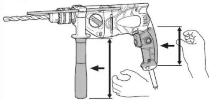
Make sure to securely hold the tool during operation. Failure to do so can result in accidents or injuries. (Fig. 10)
-
Before drilling into walls, ceilings or floors, ensure that there are no concealed power cables inside.
-
Do not wear gloves made of stuff liable to roll up such as cotton, wool, cloth or string, etc.
SPECIFICATIONS
| Model D13VH | |||
| Voltage (by areas)*1 | (110 V, 220 V, 230 V, 240 V)~ | ||
| Power input | 690 W*1 | ||
| Speed change | 1 | 2 | |
| No load speed | Forward rotation | 0 – 1000 min-1 | 0 – 3000 min-1 |
| Reverse rotation | 0 – 600 min-1 | 0 – 1800 min-1 | |
| Capacity | Steel | 13 mm | 8 mm |
| Wood | 40 mm | 25 mm | |
| Weight (without cord)*2 | 2.4 kg | ||
*1 Be sure to check the nameplate on product as it is subject to change by areas.
*2 According to EPTA-Procedure 01/2014.
STANDARD ACCESSORIES
(1) Chuck Wrench (Spec. only for keyed chuck) ..... 1
(2) Side Handle....1
(3) Depth Gauge....1
Standard accessories are subject to change without notice.
APPLICATIONS
○ Boring holes in metal, wood and plastic.
PRIOR TO OPERATION
1. Power source
Ensure that the power source to be utilized conforms to the power requirements specified on the product nameplate.
2. Power switch
Ensure that the power switch is in the OFF position. If the plug is connected to a receptacle while the power switch is in the ON position, the power tool will start operating immediately, inviting serious accident.
3. Extension cord
When the work area is removed from the power source, use an extension cord of sufficient thickness and rated capacity. The extension cord should be kept as short as practicable.
4. Selecting the appropriate drill bit
○ When boring metal or plastic Use an ordinary metalworking drill bit.
- When boring wood Use an ordinary woodworking drill bit. However, when drilling 6.5mm or smaller holes, use a metalworking drill bit.
5. Mounting and dismounting of the bit
For keyed chuck (Fig. 1)
(1) Open the chuck jaws, and insert the bit into the chuck.
(2) Place the chuck wrench in each of the three holes in the chuck, and turn it in the clockwise direction (viewed from the front side). Tighten securely.
(3) To remove the bit, place the chuck wrench into one of the holes in the chuck and turn it in the counterclockwise direction.
For keyless chuck (Fig. 2, 3)
(1) Mounting the bit
Turn the sleeve counterclockwise and open the chuck. After inserting the drill bit into the chuck as far it will go, grip the retaining ring and close the chuck by turning the sleeve clockwise as viewed from the front.
(2) Dismounting the bit
Grip the retaining ring and open the chuck by turning the sleeve counterclockwise.
NOTE
When the sleeve does not become loose any further, fi x the side handle to retaining ring, hold side handle firmly, then turn the sleeve to loosen by hand (Fig. 4).
6. Check the rotational direction (Fig. 5)
The bit rotates clockwise (viewed from the rear side) by pushing the R-side of the push button.
The L-side of the push button is pushed to turn the bit counterclockwise.
(The L and R marks are provided on the body.)
7. Fixing the side handle (Fig. 6)
Attach the side handle to the mounting part.
Rotate the side handle grip in a clockwise direction to secure it.
Set the side handle to a position that is suited to the operation and then securely tighten the side handle grip.
To attach a depth gauge on the side handle, insert the gauge into the U-shaped groove on the side handle, adjust the position of the depth gauge in accordance with the desired depth of the hole, and firmly tighten the side handle grip (Fig. 7).
8. High-speed/Low-speed changeover
Prior to changing speed, ensure that the switch is in the OFF position, and the drill has come to a complete stop. To change speed, rotate the gear shift dial as indicated by the arrow in Fig. 8. The numeral "1" engraved on the drill body denotes low speed, the numeral "2" denotes high speed.
If it is hard to turn the gear shift dial, turn the chuck slightly in either direction and then turn the gear shift dial again.
HOW TO USE
1. Switch operation
○ When the trigger is depressed, the tool rotates. When the trigger is released, the tool stops.
☐ The rotational speed of the drill can be controlled by varying the amount that the trigger switch is pulled. Speed is low when the trigger switch is pulled slightly and increases as the trigger switch is pulled more.
- The desired rotation speed can be pre-selected with the speed control dial.
Turn the speed control dial clockwise for higher speed and counterclockwise for lower speed (Fig. 9).
○ Pulling the trigger and pushing the stopper, it keeps the switched-on condition which is convenient for continuous running. When switching off, the stopper can be disconnected by pulling the trigger again.
CAUTION
If the L-side of push button is pressed for reverse bit rotation, the stopper cannot be used.
2. Drilling
○ When drilling, start the drill slowly, and gradually increasing speed as you drill.
○ Always apply pressure in a straight line with the bit. Use enough pressure to keep drilling, but do not push hard enough to stall the motor or deflect the bit.
To minimize stalling or breaking through the material, reduce pressure on drill and ease the bit through the last part of the hole.
☐ If the drill stalls, release the trigger immediately, remove the bit from the work and start again. Do not click the trigger on and off in an attempt to start a stalled drill. This can damage the drill.
○ The larger the drill bit diameter, the larger the reactive force on your arm.
Be careful not to lose control of the drill because of this reactive force.
To maintain firm control, establish a good foothold, use side handle, hold the drill tightly with both hands, and ensure that the drill is vertical to the material being drilled.
MAINTENANCE AND INSPECTION
1. Inspecting the drill bits
Since use of an abraded drill bits will cause motor malfunctioning and degraded efficiency, replace the drill bits with a new one or resharpening without delay when abrasion is noted.
2. Inspecting the mounting screws
Regularly inspect all mounting screws and ensure that they are properly tightened. Should any of the screws be loose, retighten them immediately. Failure to do so could result in serious hazard.
3. Maintenance of the motor
The motor unit winding is the very “heart” of the power tool. Exercise due care to ensure the winding does not become damaged and/or wet with oil or water.
4. Inspecting the carbon brushes
For your continued safety and electrical shock protection, carbon brush inspection and replacement on this tool should ONLY be performed by a HiKOKI Authorized Service Center.
5. Replacing supply cord
If the supply cord of Tool is damaged, the Tool must be returned to HiKOKI Authorized Service Center for the cord to be replaced.
CAUTION
In the operation and maintenance of power tools, the safety regulations and standards prescribed in each country must be observed.
GUARANTEE
We guarantee HiKOKI Power Tools in accordance with statutory/country specific regulation. This guarantee does not cover defects or damage due to misuse, abuse, or normal wear and tear. In case of complaint, please send the Power Tool, undismantled, with the GUARANTEE CERTIFICATE found at the end of this Handling instruction, to a HiKOKI Authorized Service Center.
NOTE
Due to HiKOKI's continuing program of research and development, the specifications herein are subject to change without prior notice.
Information concerning airborne noise and vibration
The measured values were determined according to EN62841 and declared in accordance with ISO 4871.
Measured A-weighted sound power level: 91 dB (A).
Measured A-weighted sound pressure level: 80 dB (A).
Uncertainty KpA: 3 dB (A).
Wear ear protection.
Drilling into metal:
Vibration emission value a_h , D = 3.0 m/s ^2
Uncertainty K = 1,5 m/s ^4
The declared vibration total value and the declared noise emission value have been measured in accordance with a standard test method and may be used for comparing one tool with another.
They may also be used in a preliminary assessment of exposure.
WARNING
☐ The vibration and noise emission during actual use of the power tool can differ from the declared total value depending on the ways in which the tool is used especially what kind of workpiece is processed; and
- Identify safety measures to protect the operator that are based on an estimation of exposure in the actual conditions of use (taking account of all parts of the operating cycle such as the times when the tool is switched off and when it is running idle in addition to the trigger time).
(1) Bohrfutterschlüssel
natural_image
Line drawing of a quill pen in an inkwell (no text or symbols)
natural_image
Line drawing of a quill pen in an inkwell (no text or symbols)
natural_image
Line drawing of a quill pen in an inkwell (no text or symbols)Hikoki Power Tools Romania S.R.L.
Ring Road, No. 66, Mustang Traco Warehouses, Warehouse
No.1, Pantelimon City, 077145, Ilfov County, Romania
- GENERAL POWER TOOL SAFETY WARNINGS
- WARNING
- PRECAUTION
- DRILL SAFETY WARNINGS
- Safety instructions for all operations
- Safety instructions when using long drill bits
- ADDITIONAL SAFETY WARNINGS
- STANDARD ACCESSORIES
- APPLICATIONS
- PRIOR TO OPERATION
- Power source
- Power switch
- Extension cord
- Selecting the appropriate drill bit
- Mounting and dismounting of the bit
- For keyed chuck (Fig. 1)
- For keyless chuck (Fig. 2, 3)
- Mounting the bit
- Dismounting the bit
- NOTE
- Check the rotational direction (Fig. 5)
- Fixing the side handle (Fig. 6)
- High-speed/Low-speed changeover
- HOW TO USE
- Switch operation
- CAUTION
- Drilling
- MAINTENANCE AND INSPECTION
- Inspecting the drill bits
- Inspecting the mounting screws
- Maintenance of the motor
- Inspecting the carbon brushes
- Replacing supply cord
- GUARANTEE
- Information concerning airborne noise and vibration
- Hikoki Power Tools Romania S.R.L.
Brand : HiKOKI
Model : D13VH
Category : Drill