
WS880T - Uncategorized ASUS - Free user manual and instructions
Find the device manual for free WS880T ASUS in PDF.

| Product Type | Workstation Motherboard |
| Socket | LGA2066 |
| Chipset | Intel C422 |
| Memory Support | DDR4, up to 288-pin DIMM slots |
| Storage Interfaces | Intel SATA 6 Gb/s, M.2 (Socket 3), U.2 |
| USB Ports | USB 3.1 Gen 2, USB 3.1 Gen 1 |
| Form Factor | Standard ATX |
| Dimensions (approx.) | 305 x 244 mm (12 x 9.6 in) |
| Weight (approx.) | 1.2 kg (2.65 lbs) |
| Power Connectors | 24-pin main, 8-pin CPU |
| BIOS Type | AMI UEFI with Q-Code debug LEDs |
| Networking | Integrated Intel? Ethernet |
| Audio | HD Audio codec with multi-channel output |
| Expansion Slots | Multiple PCIe x16 slots |
| Fan Headers | Multiple 4-pin PWM fan headers |
| Management Features | BMC LED, remote management support |
| Operating Temperature | 0°C to 40°C (32°F to 104°F) |
| Storage Temperature | -20°C to 70°C (-4°F to 158°F) |
| Warranty | Standard 3-year limited warranty |
Frequently Asked Questions - WS880T ASUS
User questions about WS880T ASUS
0 question about this device. Answer the ones you know or ask your own.
Ask a new question about this device
Download the instructions for your Uncategorized in PDF format for free! Find your manual WS880T - ASUS and take your electronic device back in hand. On this page are published all the documents necessary for the use of your device. WS880T by ASUS.
USER MANUAL WS880T ASUS
T17707
6.00 版
2020 年 12 月發行
版權說明
1.3 產品規格表
natural_image
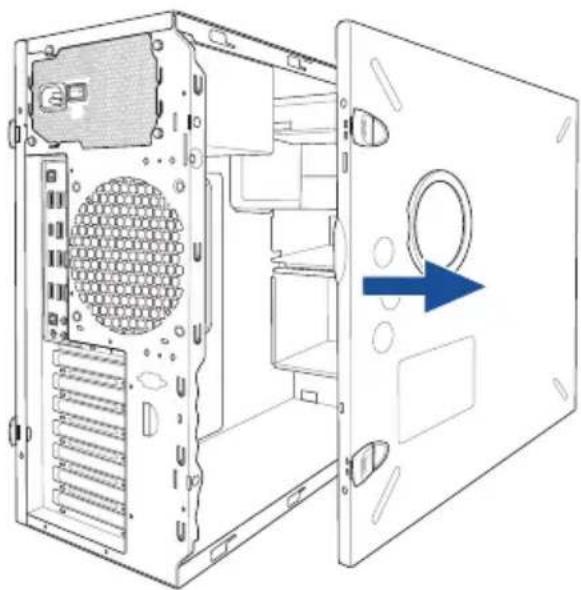
Diagram of a computer tower case with visible internal components and blue arrows indicating directional movement (no text or symbols)側蓋板固定扣
natural_image
Diagram of a server rack with an arrow pointing to a component, showing internal structure without any text or symbols.- 然後取下側蓋板,並請將其放置於一旁。
natural_image
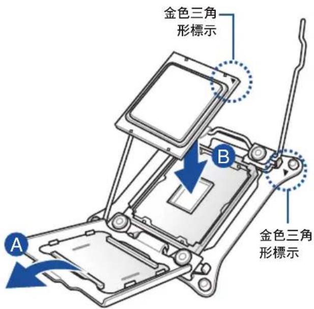
Diagram of a computer tower internal structure showing ventilation slots and a blue arrow indicating a component (no text or symbols present)2.2 中央處理器(CPU)
WS C422 PRO/SE LGA2066 Socket

3
natural_image
Technical line drawing of a mechanical component with mounting holes and a central housing (no text or symbols)WS C422 PRO/SE 288-pin DDR4 DIMM socket
記憶體建議設定
2.5 前面板的組裝

natural_image
Diagram of a computer drive bay with labeled component (no text or symbols beyond label)安裝 2.5 吋硬碟機 / SSD
natural_image
Technical line drawing of a computer chassis with mounting holes and ventilation slots (no text or symbols)natural_image
Diagram of a computer drive bay with an arrow indicating a loading or movement process (no text or symbols present)natural_image
Diagram of a connector assembly with blue arrows indicating direction (no text or symbols present)2.8 擴充卡
natural_image
Diagram of a desktop computer tower showing internal components and a close-up view of the tower's internal structure (no text or labels present)PCI-E 擋板固定扣
natural_image
Technical line drawing of a mechanical assembly with rollers and housing (no text or symbols)2.9 系統風扇
natural_image
Diagram of a computer tower rear panel with screw holes and ventilation slots (no text or labels)natural_image
Technical line drawing of a computer fan with a blue arrow pointing to a component, no text or symbols present.2.10 BIOS 更新應用程式
natural_image
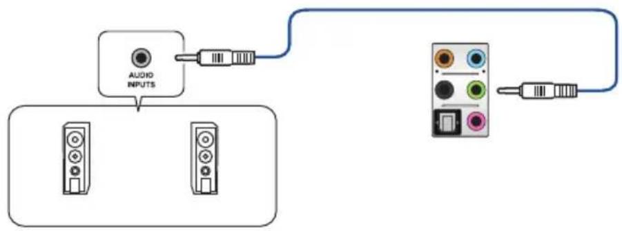
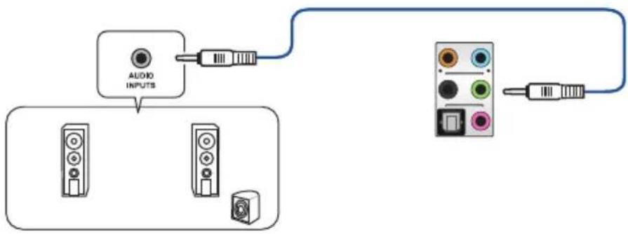
Diagram showing a microphone connected to an audio device via a cable, with no visible text or symbols.連接立體聲喇叭
flowchart
graph TD
    A["Audio INPUTS"] --> B["Device 1"]
    A --> C["Device 2"]
    D["Device 3"] --> E["Output"]
    F["Device 4"] --> G["Output"]
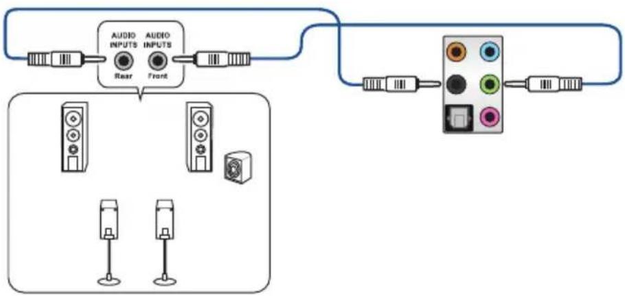
連接 2 聲道喇叭
flowchart
graph TD
    A["Audio INPUTS"] --> B["Component 1"]
    A --> C["Component 2"]
    A --> D["Component 3"]
    E["Audio Output"] --> F["Component 4"]
    E --> G["Component 5"]
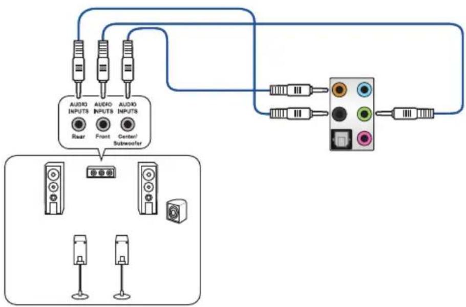
連接 4 聲道喇叭
flowchart
graph TD
    A["Audio Inputs"] --> B["Rear"]
    C["Audio Inputs"] --> D["Front"]
    B --> E["Display Unit"]
    D --> E
    E --> F["Color Indicator"]
    style A fill:#f9f,stroke:#333
    style C fill:#f9f,stroke:#333
    style E fill:#ccf,stroke:#333
    style F fill:#cff,stroke:#333
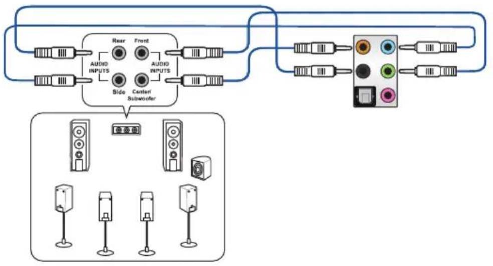
連接 6 聲道喇叭
flowchart
graph TD
    A["Audio INPUTS"] --> B["Rear"]
    A --> C["Front"]
    A --> D["Center/Subwoofer"]
    E["Audio INPUTS"] --> F["Subwoofer"]
    G["Display Unit"] --> H["Three speakers with icons"]
    I["Radio Station"] --> J["Radio button"]
連接 8 聲道喇叭
flowchart
graph TD
    A["Speaker Module"] --> B["Speaker 1"]
    A --> C["Speaker 2"]
    A --> D["Speaker 3"]
    A --> E["Speaker 4"]
    A --> F["Speaker 5"]
    G["Speaker 6"] --> H["Speaker 7"]
    G --> I["Speaker 8"]
    J["Speaker 9"] --> K["Speaker 10"]
    L["Speaker 11"] --> M["Speaker 12"]
    N["Speaker 13"] --> O["Speaker 14"]
    P["Speaker 15"] --> Q["Speaker 16"]
    R["Speaker 17"] --> S["Speaker 18"]
    T["Speaker 19"] --> U["Speaker 20"]
    V["Speaker 21"] --> W["Speaker 22"]
    X["Speaker 23"] --> Y["Speaker 24"]
    Z["Speaker 25"] --> AA["Speaker 26"]
    AB["Speaker 27"] --> AC["Speaker 28"]
    AD["Speaker 29"] --> AE["Speaker 30"]
    AF["Speaker 31"] --> AG["Speaker 32"]
    AH["Speaker 33"] --> AI["Speaker 34"]
    AJ["Speaker 35"] --> AK["Speaker 36"]
    AL["Speaker 37"] --> AM["Speaker 38"]
    AN["Speaker 39"] --> AO["Speaker 40"]
    AP["Speaker 41"] --> AQ["Speaker 42"]
    AR["Speaker 43"] --> AS["Speaker 44"]
    AT["Speaker 45"] --> AU["Speaker 46"]
    AV["Speaker 47"] --> AW["Speaker 48"]
    AX["Speaker 49"] --> AY["Speaker 50"]
主機板資訊

3. 訊息指示燈(MESLED1)
WS C422 PRO/SE BMC LED
5. Q-Code 指示燈
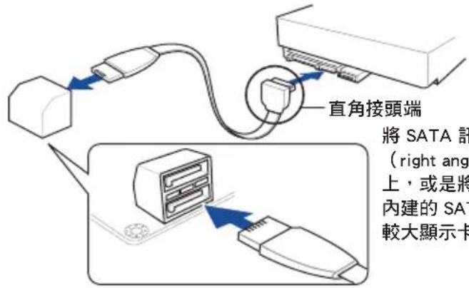
WS C422 PRO/SE Intel® Serial ATA 6 Gb/s connectors
WS C422 PRO/SE USB 3.1 Gen 2 front panel connector
WS C422 PRO/SE USB 3.1 Gen 1 connector

USB 3.1 Gen 1 模組為選購配備,請另行購買。

WS C422 PRO/SE Internal VGA connector
WS C422 PRO/SE System panel connector
WS C422 PRO/SE System panel connector
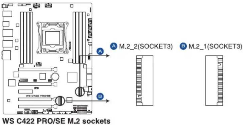
19. U.2 連接埠 (U.2)
20. M.2 (NGFF) 插槽 (M.2\_1(Socket 3); M.2\_2(Socket 3))
本插槽提供安裝一個 M.2 裝置。


WS C422 PRO/SE ADD header

快速鍵
系統超頻設定 RAID 設定
調整系統設定
請依照以下步驟調整設定:


新增項目至我的最愛
請依照以下步驟新增項目至我的最愛:
Hyper-Threading [ALL]
CPU Power Management Control
本項目用來管理與設定處理器電力。
Enhanced Intel SpeedStep Technology
本項目可以讓兩個以上的頻率被支援。
設定值有:[Auto] [Enabled] [Disabled]
Turbo Mode
Autonomous Core C-State
設定値有:[Auto] [Gen1 (2.5 GT/s)] [Gen2 (5 GT/s)] [Gen3 (8 GT/s)]
M2_2 and U.2 Switch Function
設定值有:[Disabled] [Enable (S4+S5)] [Enable (S5)]
Next Boot after AC Power Loss
Boot Devices Control
本項目用來選擇想要啟動的裝置類型。
設定值有:[UEFI and Legacy OPROM] [Legacy OPROM only] [UEFI only]
Boot from Network Devices
本項目用來選擇想要執行的網路裝置。
設定值有:[Ignore] [Legacy Only] [UEFI driver first]
Boot from Storage Devices
本項目用來選擇想要執行的儲存裝置類型。
設定值有:[Ignore] [Legacy Only] [UEFI driver first]
Boot from PCI-E/PCI Expansion Devices

狀態說明:
Load/Save Profile from/to USB Drive
4.7.5 Graphics Card Information
本選單顯示繪圖卡的相關資訊。
GPU Post
Discard Changes & Exit
Launch EFI Shell from USB devices
- 點選 Load Driver。
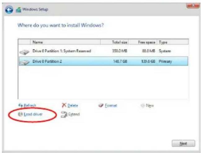
WARNING: ALL DATA ON SELECTED DICKS WILL BE LOST. Are you sure you want to create this volume? (Y/N)
| Code Description | |
| 00 Not used | |
| 02 microcode | |
| 03 CACHE_ENABLED | |
| 04 PCH initialization | |
| 06 CPU_EARLY_INIT | |
| 10 PEI Core is started | |
| 11 - 14 Pre-memory CPU initialization is started | |
| 15 - 18 Pre-memory System Agent initialization is started | |
| 19 - 1C Pre-memory PCH initialization is started | |
| 2B - 2F Memory initialization | |
| 30 Reserved for ASL (see ASL Status Codes section below) | |
| 31 Memory Installed | |
| 32 - 36 CPU post-memory initialization | |
| 37 - 3A Post-Memory System Agent initialization is started | |
| 3B - 3E Post-Memory PCH initialization is started | |
| 4F DXE IPL is started | |
| 50 - 53 Memory initialization error. Invalid memory type or incompatible memory speed | |
| 4F DXE IPL is started | |
| 54 Unspecified memory initialization error | |
| 55 Memory not installed | |
| 56 Invalid CPU type or Speed | |
| 57 CPU mismatch | |
| 58 CPU self test failed or possible CPU cache error | |
| 59 CPU micro-code is not found or micro-code update is failed | |
| 5A Internal CPU error | |
| 5B Reset PPI is not available | |
| 5C - 5F Reserved for future AMI error codes | |
| E0 S3 Resume is stared (S3 Resume PPI is called by the DXE IPL) | |
| E1 S3 Boot Script execution | |
| E2 Video repost | |
| E3 OS S3 wake vector call | |
| E4 - E7 Reserved for future AMI progress codes | |
| E8 S3 Resume Failed | |
| E9 S3 Resume PPI not Found | |
| EA S3 Resume Boot Script Error | |
| EB S3 OS Wake Error | |
| EC - EF Reserved for future AMI error codes | |
| F0 Recovery condition triggered by firmware (Auto recovery) | |
| F1 Recovery condition triggered by user (Forced recovery) | |
| F2 Recovery process started | |
| F3 Recovery firmware image is found | |
| F4 Recovery firmware image is loaded | |
| F5 - F7 Reserved for future AMI progress codes | |
| F8 Recovery PPI is not available | |
| F9 Recovery capsule is not found | |
Q-Code 列表(續上頁表格)
| Code Description |
| FA Invalid recovery capsule |
| FB - FF Reserved for future AMI error codes |
| 60 DXE Core is started |
| 61 NVRAM initialization |
| 62 Installation of the PCH Runtime Services |
| 63 - 67 CPU DXE initialization is started |
| 68 PCI host bridge initialization |
| 69 System Agent DXE initialization is started |
| 6A System Agent DXE SMM initialization is started |
| 6B - 6F System Agent DXE initialization (System Agent module specific) |
| 70 PCH DXE initialization is started |
| 71 PCH DXE SMM initialization is started |
| 72 PCH devices initialization |
| 73 - 77 PCH DXE Initialization (PCH module specific) |
| 78 ACPI module initialization |
| 79 CSM initialization |
| 7A - 7F Reserved for future AMI DXE codes |
| 90 Boot Device Selection (BDS) phase is started |
| 91 Driver connecting is started |
| 92 PCI Bus initialization is started |
| 93 PCI Bus Hot Plug Controller Initialization |
| 94 PCI Bus Enumeration |
| 95 PCI Bus Request Resources |
| 96 PCI Bus Assign Resources |
| 97 Console Output devices connect |
| 98 Console input devices connect |
| 99 Super IO Initialization |
| 9A USB initialization is started |
| 9B USB Reset |
| 9C USB Detect |
| 9D USB Enable |
| 9E - 9F Reserved for future AMI codes |
| A0 IDE initialization is started |
| A1 IDE Reset |
| A2 IDE Detect |
| A3 IDE Enable |
| A4 SCSI initialization is started |
| A5 SCSI Reset |
| A6 SCSI Detect |
| A7 SCSI Enable |
| A8 Setup Verifying Password |
| A9 Start of Setup |
| AA Reserved for ASL (see ASL Status Codes section below) |
| AB Setup Input Wait |
Q-Code 列表(續上頁表格)
| Code Description | |
| AC | Reserved for ASL (see ASL Status Codes section below) |
| AD | Ready To Boot event |
| AE | Legacy Boot event |
| AF | Exit Boot Services event |
| B0 | Runtime Set Virtual Address MAP Begin |
| B1 | Runtime Set Virtual Address MAP End |
| B2 | Legacy Option ROM Initialization |
| B3 | System Reset |
| B4 | USB hot plug |
| B5 | PCI bus hot plug |
| B6 | Clean-up of NVRAM |
| B7 | Configuration Reset (reset of NVRAM settings) |
| B8 - BF | Reserved for future AMI codes |
| D0 | CPU initialization error |
| D1 | System Agent initialization error |
| D2 | PCH initialization error |
| D3 | Some of the Architectural Protocols are not available |
| D4 | PCI resource allocation error. Out of Resources |
| D5 | No Space for Legacy Option ROM |
| D6 | No Console Output Devices are found |
| D7 | No Console Input Devices are found |
| D8 | Invalid password |
| D9 | Error loading Boot Option (LoadImage returned error) |
| DA | Boot Option is failed (StartImage returned error) |
| DB | Flash update is failed |
| DC | Reset protocol is not available |
| Code Description | |
| 03 System | is entering S3 sleep state |
| 04 System | is entering S4 sleep state |
| 05 System | is entering S5 sleep state |
| 30 System | is waking up from the S3 sleep state |
| 40 System | is waking up from the S4 sleep state |
| AC | System has transitioned into ACPI mode. Interrupt controller is in PIC mode. |
| AA | System has transitioned into ACPI mode. Interrupt controller is in APIC mode. |