EPR-04-DIN - Uncategorized ENTES - Free user manual and instructions
Find the device manual for free EPR-04-DIN ENTES in PDF.


| Product Type | Power Meter (Energy Analyzer) |
| Model | EPR-04-DIN (EPR-04S with serial communication) |
| Brand | ENTES |
| Measuring Voltage (L-N) | 10-300 VAC |
| Measuring Voltage (L-L) | 10-500 VAC |
| Frequency | 45-65 Hz |
| Current Input (direct) | 0.05-5.5 A |
| Current Input (with CT-25) | 2-120 A |
| Auxiliary Supply Consumption | < 4 VA |
| Measurement Category | CAT III |
| Accuracy Class | 1 ±1 digit (10%-110% of full scale) |
| Display | Red LED, 4 digits |
| Serial Interface (EPR-04S) | MODBUS RTU, RS485, optically isolated |
| Baud Rate (EPR-04S) | 2400, 4800, 9600, 19200, 38400 bps (programmable) |
| Pulse Outputs | 2x NPN transistor, max 50 mA, 5-24 VDC |
| Digital Inputs | 2x 12-48 VAC/DC |
| Operating Temperature | -5°C to +50°C |
| Weight (with box PR-19/PK-26) | 0.45 kg |
| Protection Class (front panel) | IP40 |
| Mounting | Panel mounted (cutout 45x45 mm) |
| Wire Cross-section | Up to 2.5 mm² |
| Insulation | Double insulation Class II |
| Demand Time | 1-60 min (programmable) |
Frequently Asked Questions - EPR-04-DIN ENTES
User questions about EPR-04-DIN ENTES
0 question about this device. Answer the ones you know or ask your own.
Ask a new question about this device
Download the instructions for your Uncategorized in PDF format for free! Find your manual EPR-04-DIN - ENTES and take your electronic device back in hand. On this page are published all the documents necessary for the use of your device. EPR-04-DIN by ENTES.
USER MANUAL EPR-04-DIN ENTES
d. Even, 8 Data Bits, 2 Stop Bits
ansigtox
0 msn: darbe periyodu
0 msn. darbe penisliči
mA
V DC max 30 VDC
VAC/DC
50%
ED Denley
DV:26
bmp-Sraf II (□)
n conc(1)
in January
6.
10.4726 (2013)
102
(附注:1) 电话:025
(PHA-12 PHE-26)
m = 311
Eng Cnt :
E-1 (Enerji Sayacı 1): on
E-2 (Enerji Sayao 2): on
PULSE
rAt 10 (Oran) : 1k
0-1 (Ckis 1): A.1
o-2 (Çkış 2) : r-L
| Cree | A (VIII) (Import Aoff Ener) | XIV (Toplam Aoff Gic) |
| W(Aoff Gic) | AE (kWh) (Export Aoff Ener) | XIVr (Toplam Resolf Gic) |
| Wr (Resert Sclc) | n (kWh) (Resist Industif Ener) | 2xV (Toplam Seral Gic) |
| Vr (Seral Gic) | n(kWh) (Resistif Kapastif Ener) |
4.3. Pulse Çıkışı-2 (Pulse o-2):
E-1: E-1" says on skill from E-3" says on symmet. (Sedice "E-3" saysome
parametresidir
(2) Register says: MSB
XX CRC MSB
XX CRC LSB
(1) Register says: MGB (2) Register says: USB
04 Витя лавки
00 Data MS8
C8 Data LSB
64 Data LSB
XX CRC MSB
XX CRC LSB
- Respondents of the U.S. (2017) have been registered

flowchart
graph TD
    A["TR3-XGND"] --> B["EPR-045-247"]
    B --> C["KUVE/LENDRICI"]
    C --> D["EPR-045-31"]
    D --> E["EPR-045-2"]
    E --> F["EPR-045-1"]
    F --> G["RS486/RS332 XONVERTÖR"]
    G --> H["PC"]
    style A fill:#f9f,stroke:#333
    style H fill:#ccf,stroke:#333
    note1["MAX. 1200 mt"]
    note2["MAX. 1200 mt"]
    note3["PC"]
    note4["MAX. 1200 mt"]
    note5["PC"]
    note6["PC"]
    note7["PC"]
    note8["PC"]
    note9["PC"]
    note10["PC"]
    note11["PC"]
    note12["PC"]
    note13["PC"]
    note14["PC"]
    note15["PC"]
    note16["PC"]
    note17["PC"]
    note18["PC"]
    note19["PC"]
    note20["PC"]
    note21["PC"]
    note22["PC"]
    note23["PC"]
    note24["PC"]
    note25["PC"]
    note26["PC"]
    note27["PC"]
    note28["PC"]
    note29["PC"]
    note30["PC"]
    note31["PC"]
    note32["PC"]
    note33["PC"]
    note34["PC"]
    note35["PC"]
    note36["PC"]
    note37["PC"]
    note38["PC"]
    note39["PC"]
    note40["PC"]
    note41["PC"]
    note42["PC"]
    note43["PC"]
    note44["PC"]
    note45["PC"]
    note46["PC"]
    note47["PC"]
    note48["PC"]
    note49["PC"]
    note50["PC"]
    note51["PC"]
    note52["PC"]
    note53["PC"]
    note54["PC"]
    note55["PC"]
    note56["PC"]
    note57["PC"]
    note58["PC"]
    note59["PC"]
    note60["PC"]
    note61["PC"]
    note62["PC"]
    note63["PC"]
    note64["PC"]
    note65["PC"]
    note66["PC"]
    note67["PC"]
    note68["PC"]
    note69["PC"]
    note70["PC"]
    note71["PC"]
    note72["PC"]
    note73["PC"]
    note74["PC"]
    note75["PC"]
    note76["PC"]
    note77["PC"]
    note78["PC"]
    note79["PC"]
    note80["PC"]
    note81["PC"]
    note82["PC"]
    note83["PC"]
    note84["PC"]
    note85["PC"]
    note86["PC"]
    note87["PC"]
    note88["PC"]
    note89["PC"]
    note90["PC"]
    note91["PC"]
    note92["PC"]
    note93["PC"]
    note94["PC"]
    note95["PC"]
    note96["PC"]
    note97["PC"]
    note98["PC"]
    note99["PC"]
Boyutlar


POWERMETER EPR-04 / EPR-04S
TECHNICAL DATA
Operating Voltage (Un)
Operating frequency (f)
Auxiliary supply Power Consumption
Measuring Input Power Consumption
v
lin
Measuring Range
Measuring Category
Class
Voltage Transformer Rado
Current Transponder Na
Max. 05 x 15 Demand Time
Serial Interface (for EPM-04S)
Baud Rate (for EPM-04S)
Address (for EPM-049
Parity (for EPM-04S)
Pulse Output
Switch Period
Operation Current
Operation Voltage
Input
Ambient Temperature
Display
Dimensions Equivalent 1
Box Protection Class
Box Material
Installation
Wire Crossection (for terminal block)
Weight
Installation Category
Please look at the back labels on
the device
45-65 Hz
< 4 VA
< TVA
10-300VAC 45-65FZ (L-N)
10-500VAC 45-65F2 (L-C)
0.05 - 5.5 A-
2-120 A = (10F LT-25)
0...215 M(W,VAR,VPA)
CAT III
1±1digit [(%10-%110) xFull Scale]
0.1...4000.0
1...2000
40.000
1-60 min. (programmable)
MODBUS RTL (RS 485)
Optically isolated, programmable
2400-38400 bps
1-247
No, odd, Even, 8 Data Bits, 2 Stop Bits
NPN Transistor
Min. 100 msec pulse period
80 msec pulse width
Max. 50 mA
5....24 V DC, max. 30 VDC
12..48 V DC
-5°C; +50°C
Rod LED Display
PR-19, PK-26
Double Insulation-Class II (10)
IP 40
Non-flammable
Panel Mounted (PTF-19)
Hall Mol
2.5 10%
0.45 kg (PA-19, PA-26)
Class III
Factory Settings
Trafo
Ctr (Current Transformer Ratio) : 0001 trn (Turn number for CT-25 device): 01 Utr (Voltage Transformer Ratio) : 0001.0 CAL (Calculation Method) : 1
Pin : 0000 (Not Activated)
RS-485
Adr (Address) : 1
E.1 (Energy Counter 1): on
E-2 (Energy Counter 2) : on
PULSE
rÂt uo (Batió) : 1k
o-1 (Output 1): A-I
o-2 (Output 2) r-l
dEti (Delay Time) : 15

A3615/Rev.B
POWERMETER EPR-04 / EPR-04S
General
EPR-04/04S is a microprocessor based device which is developed for measuring the power and energy values in an Electrical Network. Measured parameters are displayed in 4 displays separately EPR-04S has an MODBUS serial communication interface.

flowchart
graph TD
    A["POWERMETER EPR-045"] --> B["ESC button"]
    A --> C["Max LED"]
    A --> D["SET button"]
    A --> E["Minimum LED"]
    A --> F["Demand LED"]
    B --> G["ESC button"]
    C --> H["Max LED"]
    D --> I["SET button"]
    E --> J["Minimum LED"]
    F --> K["Demand LED"]
    L1_1 --> M1_1
    L2_1 --> M2_1
    L3_1 --> M3_1
    M1_1 --> N1_1
    M2_1 --> N2_1
    M3_1 --> N3_1
    N1_1 --> O1_1
    N2_1 --> O2_1
    N3_1 --> O3_1
    O1_1 --> P1["Phase Displays"]
    O2_1 --> Q["Total Display"]
    O3_1 --> R["UP button"]
    O4["DOWN button"] --> S["SET button"]
    S --> T["ESC button"]

Using of EPR-04/045:
Parameters (Cose; W; VAr; VA; kWh, kVarh) are monitored in L1, L2, L3 displays by scrolling UP/DOWN buttons. Total Active (EW), Total Reactive Power (EVA), Total Apparent Power (EVA) and Cosφ values and average values of these parameters are monitored in 4th display.
Digital Input
EPR-04/045 has 2 digital inputs. Digital inputs have 2 functions. - When a remote device has activated, situation of this device which is connected to the digital input, can be monitored according to data register (Battery, thermostat, circuit breaker and motor position). - Controlling energy counters and determining which energy counter will be active (Example: it is used for measuring of energy separately at the using of network and generator).
Energy Pulse Outputs
EPR-0404S has 2 Energy Pulse Outputs. These outputs give the pulses only for E-1 (Energy Counted).
Pul1 and Pul2: In "o-1 (Pulse1)", "o-2 (Pulse2)" menus which are in the pulse menu, device give pulse according to selected energy parameters as [Active energy (ACI, A-I, A-E), Reactive energy (rEA, r-L, r-C)]. Please refer to the pulse menu for the coefficients of energies.
Monitoring of Min., Max. and Max. Demand Values: Min. and max. values are defined for W, VAr, VA, IW, EVAr, EVA; demand values are defined for W, VAr, VA, IW, EVA, EVAr.
If measured instant value is smaller than min. value which was stored before, it is stored as new min. value. If measured instant value is greater than max. value which was stored before, it is stored as new max. value. Demand value is the average value of the measured values in demand time (15 minutes). If one of defined parameters is displayed (ie. "W") when demand button is pressed too min., max or max. demand values are displayed. When an undefined parameter is displayed (ie. "Case") if demand button is pressed, instant value is continued to display.
H-L-M LEDs
H-L-M LEDs are dedicated to displaying the min., max. and max. demand values according to selected parameters.
H: Maximum Value, L: Minimum Value, M: Max. Demand Value
Calculation Methods for Active / Reactive Power Values If the led on the most right side blinks it represents that active / reactive power's direction is reversed.
There are two methods for calculating total active and total reactive powers: 1) Active / Reactive power can be calculated by summing import and export values and displaying as a single value.
2) Active / Reactive power can be calculated according to direction as import / export.
Note:
1) The dot at the most right digit of the fourth display (During SW is displayed) represents that displayed value is export active power value. Vice versa, displayed value is import active power value.
2) The dot at the most right digit of the fourth display (During EVAr is displayed) represents that displayed value is capacitive reactive power value. Hence, displayed value is indicative reactive power value.
3) The displayed parameter will not change if power is off after 30 seconds of stand-by (ie. W).
Measured Parameters:
| CaspW (Active Power)VA (Reactive Power)VA (Apparent Power) | AI (With) (Import Active Energy)AE (With) (Export Active Energy)ii (iVAth) (Import Reactive Energy)iii (iVAnt) (Export Reactive Energy) | ΣW (Total Active Power)ΣVA (Total Reactive Power)ΣVA (Total Apparent Power) |
FUNCTIONS OF BUTTONS

When W led lights, it shows max power values which are measured instantaneously and it shows total max demand values. Also it is used for moving upwards in the menu.

When Wied lights, it shows min power values which are measured instantaneously and it shows total demand values. Also it is used for moving downwards in the menu.

It is used for passing between parameters such as W, Var, VA, KWh, KV/Mh, once. When it is praced for 3 seconds, adjustment mode is entered. In the adjustment mode it is used for saving parameters and moving to the sub menu.

In the adjustment mode, it is used for entering to the upper menu or it is used for quitting from the adjustment mode without saving the values.

I user password is activated and set button is pressed for seconds, a pin code is required in order to enter to the menu.
Current Transformer Ratio Setup

(This menu is not available in the devices which are adapted with CT-26.)
In this menu, current transformer ratio is set between 1 - 2000.
Note: If the current transformer is not used between the system and ETR, 0.4107, current transformer ratio is required as it's
Example: If a current transformer which has a ratio of 250/5A is
used between the system and

ress SET button for 3 seconds (trA Fo menu is displayed)

lose SET button, t/A Fo Clm menu is displayed (in CT-26 adopted
lot: 1A FoLIt: menu can be dispaved by spilling the UP/DOWN
uttons

图1
Press SET button. Binding the first digit of displayed value approaches. In A Fo

Enter the blinking digit value by scrolling UP/DOWN buttons. Switch to the other digits by using SET button, use ESC button to go to previous digit. After you entered the last digit press SET button, "trA Fo Ctr /trA Fo trn /trA Fo Utr" is displayed. "on" can be selected by scrolling UP/DOWN buttons. (Data is entered but is not activated yet. For activating the new data please follow the below steps).

Free ESC button one by one until "SAU E SET YES" is displayed.

press SET button. When "SAJE SET YES" is displayed, if you press ESC button or choose "no" option instead of "YES" option by using IP-DCWN buttons, new data will be cancelled and previous value will be activated.
POWERMETER EPR-04 / EPR-04S
Programming the Turn Number:


Voltage Transformer Ratio Setup
In this menu, voltage transformer ratio is set between
Cn 10000,1-4000,0
Fo Utr Note: If the voltage transformer is not used between the system and EPR-04/04S; voltage transformer ratio is entered as 1. Example: If a voltage transformer which has a ratio of 34.5KV/100V is used between the system and EPR-04/04S; Voltage transformer ratio is entered as 34b. (3450V/100)
Reactive Energy Calculation Method Setting
CAL Three different methods exist for reactive energy calculation in EPR-04/04S. Brief informations about these methods are explained in below able
CLC Related values which must be entered in the menu are also indicated in the table in order to select reactive power calculation method for mechanical and digital energymeters.
Mechanical Enzymeter | Digital Enzymeter | Reactive Energy
| Number of methods (n) | Each point equivalent | Q | Unadjusted |
| 0 | 1 | 5irc solution of voltage vector and multiply with current | It is the most preferred reactive power calculation methods. |
| 2 | 3 | 1 solution (n) | Total value of the multiplication of Vp and Ip returns up to 14th harmonics. This calculation method is mostly preferred for network analysis. |
| 4 | 5 | -P | Power Triangle Method : According to this method 0 = 3 × 10⁻⁶ (i: Reactive power 3: Active power 7: Apparent power |


Demand Time Setup:

In this menu, demand time is set between 1-60 minutes.

Press SET button for 3 seconds (trA Fo menu is displayed)

By using UP-DCW by buttons find "dE t" menu. df

By using UP-DOWN buttons, enter the value to the first digit.

Press SET button (Second digit blinks)

By using UP-DOWN buttons, enter the value to the second digit.

Press SET button, "dE 3" is displayed. (Data is entered but is not
Note: Measured electrical parameters which are saved to the memory are not affected from the electric internations.
In the iES El de E-1 / E-2 menu; when you choose yes and quit from all menus, if you confirm the changes, min. and max. values of all parameters or values of energymeters are erased at the same time. Follow the below steps in order to erasing the value of min., max., E-1 and E-2: In the measurement position

Prep-SET button 3 seconds (11A Formen is displayed)

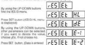

For activating the new data please follow the below steps).

Press ESC button one by one until "SAUE SET YES" is displayed.

Press SET button. When "SAUE SET YES" is displayed, if you press ESC button or choose "no" option instead of "YES" option by using UP-DOWN buttons, new data will be cancelled and previous value will be activated.
POWERMETER EPR-04 / EPR-04S
PK 26 Box Connection Diagram
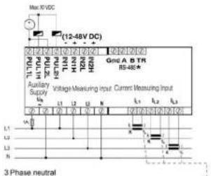
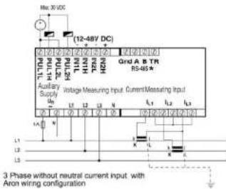

*Available only for EPR-645
Note: For CT-25 models:
k: When CT-25 is used, Red cable is connected to k terminal.
l: When CT-25 is used, Black cable is connected to l terminal.
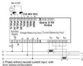
POWERMETER EPR-04 / EPR-04S
PR 19 Box Connection Diagram

3 Phase neutral

3 Phase without neutral current input with Aron wiring configuration

- Phase without neutral

3 Phase without neutral current input with Aren wiring configuration
\*Available only for EPR-045
Note: For CT-25 models:
k: When CT-25 is used, Red cable is connected to k terminal.
l: When CT-25 is used, Black cable is connected to l terminal.
POWERMETER EPR-04 / EPR-04S
Pulse Menu
PUL In this menu, three parameters can be selected: "PUL SE rAt", "PUL SE p-1", "PUL SE p-2".
PUL SE rAt ip : Pulse ratio can be set as :
SE 1, 10, 100 (wh/YArh/VA); 1, 12, 100 (kwh/KVArh/KVA); 13Meh/BVArh/MVA
PUL 5E o-1: if this parameter is selected, in every increase in output 1.
one pulse is counted. Output 1 parameter can be set as: ADt (Export/Import), A-I (Active import), A-E (Active Export), sEA (Inductive
/ Capacitive), r-L (Reactive Inductive), r-C (Reactive Capacitive).
PUL SE 6-2 : In one parameter is selected, in every increase in output 2, one pulse is counted. Output 2 parameter can be set as :
ACI (Export/Imports, A-I (Active Import), A-E (Active Export), rEA (Inductive / Capacitive), r-I (Reactive Inductive), +C (Reactive Capacitive)).
(1)
SET Press SET button for 3 seconds (TRA Fo menu is displayed)


C.16. (3) Active L-1, L-2 couleurs for energy counting world depending on any parameter.
1:Activate T-1
+2: Activate "E-1 / E-2" counters when digital input 2 is on (n=1).
B-2, "E-1" does not count when "E-2" is activated. (Only for "E-1")
E-1, "E-2" does not count when "E-1" is activated. (Only for "E-2")
Note: Counting status is undefined if E-2 is selected on E-1 and if E-1 is selected
cn E-2
When the status is defined as above, both energy counters count while digital input is not on (-1) , but if it will use one or better digital input are so (or 11) then counters will
表决结果:
Net court.
GET


Press SET better. After: SALE, SET: SET is designed.
Hosa SET button. When 'SAGE' set, yes is displayed, if you press ESC button or choose "no" option instead of "yes" option
by using UP-DOWN buttons, now data will be cancelled and
previous value will be activated.
User password Setup
D. In this menu user passwords is defined and activated.
You must define and activate a 4 digit user password for preventing driving passwords from the ill-leaf user.
device settings from the legal usage. There are 2-sub menu under the Fin menu.
Changing of User Password:


nSE for championing this year consisted to the procurement results


(2) Using of OSAV-3.0, which has the old customer


button remember the new password.
Please SET button, Pin CHA.ngl is displayed. Data is entered, but is not activated here. For setting the active data places being the brief
(58) Not activated yet. For activating the new data please follow the below steps.
Page ESC button one by one until (FALL SE) >ES! appears at the
ESC 7.500 ESC screen (one of one mini (340 sec 3 GHz) displays in the display.
Press SET button when (SAU SET yES) appears at the display. (When
(SET) SAD Set YES appears at the display, if you press ESC button or choose "no" option instead of "yes" option, you pull from adjustment.
choose the "open" website of your options you can get in a solution menu without saving new setsga and device continues to work with

Activating the user password


Note: Factory default value of user password is "0000"


Bu using UP-DOWN buttons, find "Pin" menu.


SET Press SET button. First digit of the displayed value is lifelong.
Enter the blinking digit value by scrolling UP/DOWN buttons.
Switch to the other digits by using SET button, use ESC button
(BET) to go to previous digit. After you entered the last digit press SET, https://doi.org/10.103456789.
button: "P" not off to display you. On "Last" be directed by scrolling UP/DOWN buttons. (Data is entered but is not activated
yet. For activating the new data please follow the below steps).
Press ESC button one by one until "SALU E. SEL vES" is displayed.
From the context of the 1974-2015, we are employed. If you
Press SET button, when SHORE SET YES is displayed, if you press ESC button or choose "no" option instead of "YES" option
by using UP-DOWN buttons, new data will be cancelled and
previous value will be activated
POWERMETER EPR-04 / EPR-04S
Serial Communication (Available only for EPR-04S)
EPR-04S has MODBUS RTU communication protocol which is optical isolated. All measured parameters can be transfer to the computer. Transformer ratios and communication parameters can be set. Saved demand and energy values can be reset.
Parameter Settings
Address Parameters : Value can be enter between 001-247. Baud Rate Parameters : Value can be selected as 2400, 4800, 9600,
19200 and 38400 bps.


MODBUS RTU PROTOCOL (Available only for EPR-04S)
Standart MODBUS RTU message is shown below.
| T | ADDRESS8 BIT | FUNCTION8 BIT | DATAXABBT | CRCH | CRCL | T |
The T times corresponds to a time in which data must not be exchanged on the communication bus to allow the connected devices to recognize the end of one message and the beginning of another. This time must be at least 3.5 characters at the selected baud rate. Adsets range (1:247) is address of the connected device. The data field contains data sent to the slave by master or data sent to master by slave.
CRC is a error check method by using MODBUS RTU protocol and consists of 2 bytes.
Available Modbus Function:
| 03H | READ HOLD REGISTERS |
| 06H | PRESET SINGLE REGISTER |
| 10H | PRESET MULTIPLE REGISTERS |
Read Hold (03) function is used for reading measured values and set value. If any request of reading of a register, excepted mentioned in register table, device will send an error message. For example to read phase1 voltage by sending a message to the device
01 00 00 00 00 02 XX XX
01 Device address
03 Function
00 MSB address
14 LSB ✅HDD 00 Registrant number MSB
02 Register number 1 SB
XX CRC MSE
XX CRC LSB
Preset Single Register (D6) function is used for writing the setting values, existing the energy counter or resetting the min., max., demand values. Current transformers ratio can be set 0-2000, voltage transformer ratio can be set 1-RXXO, Min., Max. and Demand values can be only clear. If sent value is outside of this range device responds with an error message. La. Setting CT as 100.
01 06 80 02 90 64 XX XX
01 Device 36 Function
06 Function M28
© LSB address
(1) Cash MSB
64 Data LS8
XX CRC MSB
XX CRC LBB
Preset Multiple Register(10H) is used to set more than one register at same
time.
- Setting CT 88 100, 01 as 20:5, 01:10:40:00:20:03:04:00:08:00:64
01 Devlon Acidtris
10 Function
30 MSB address
00 LBS address
00 Register number MSE
(2) Register
- Byte down
- Data MS8
C8 Data L5B
00 Data MSB
64 Data L58
XX CRC MSB
XX CHC LSB
Digital Inputs (Available only for EPM-04S)
Digital input are sent in 16 bit hexadecimal format as below

If 12-40 V AC / DO is applied to In1 (Input 1), 0 (zero) bit of DIN register is set as "1". Otherwise, 0 (zero) bit is set as "0".
If 12-48 V AC / DD is applied to int? (Input 2), 1st bit of DIN register is set as "1". Otherwise, 1st bit is set as "0".
The Parameters are sent in 38bit Hexadecimal format. For Example, 230.0V voltage will be sent as 000008FCH. Cose values shall be divided to 1000.0B0 Cose will be sent as 000003D4H. Energy values are sent in 64 bytes. 1234567890123456789 Wh = AB 54 A9 8C EE 1F 0A D2 Wh
Specifications for data cable:
-24 AWG of BICHER
-Less than 100 chm/km
Nominal characteristic impedance at 100 MHz of 100 GHz Less than 60 pF/m mutual capacitance (between two wires in a pair)
- Less than 60 pF/m mutual capacitance (between two wires in a pair) - Less than 120 pF/m mutual pair capacitance / the capacitance
between one wise and all others connected to earth).
- Terated Pair
ERROR CODES (Available only for EPR-04S)
Save device (EPR-04S) sends error message when receive any missing query.
01 Invalid Functions: If any message except given above is used, then 01 error
messages will be sent.
02 Invalid Register: Error 02 will be send when a leading of a register a requested, except the registers which mentioned in table.
03 Invalid data: If any different value is been set for dedicated Transformer values and nonzero for demand value; then error message 03 will be sent.
POWERMETER EPR-04 / EPR-04S
EPM-04S COMPUTER CONNECTION
31 DEVICES CAN BE CONNECTED AT THE SAME LINE

flowchart
graph LR
    A["Max 1200 mL"] --> B["RS485/R232 CONVERTER"]
    B --> C["PC"]
    D["TR B A GND"] --> E["EPM-045-31"]
    F["TR B A GND"] --> G["EPM-045-2"]
    H["TR B A GND"] --> I["EPM-045-1"]
MAX. 247 DEVICES CAN BE CONNECTED AT SAME LINE BY USING REPEATER

flowchart
graph LR
    A["EMR-04S247"] --> B["REPEATER"]
    B --> C["RS485RS232 CONVERTER"]
    C --> D["PC"]
    style A fill:#f9f,stroke:#333
    style B fill:#ccf,stroke:#333
    style C fill:#cfc,stroke:#333
    style D fill:#fcc,stroke:#333
Dimensions
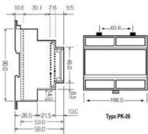

1.45 km (RR 19, RV 20)
2.60元(本位P025)
Kessler III
Werkseinstellungen
Transformers
The following Entity: South Korea
- Mr. NHF, order AR-Taster, with an 60"Fox Cut 5.1" order "Fox
©
CITE-2.
[Figure]
(▲) (▼) MRC-NSR-O&R-AS-RS-R, MANH-SR-ENG-CNT-L-T-OSR-ENG CNT-E-27
[NO TEXT]
↓
MILKEL AR, other SET Tages 2 CUS 95
(1) 2017 (ABP, AB-508 SET-Tusion, P. alii 88169E)
V
↓
1
SET
- 1.000,000,000,000,000,000,000,000,000,000,000,000,000,000,000,000,000,000,000,000,000,000,000,000,000,000
Exterior Spin out Srl. Torso for "Sociurnian" Trl. 60° Menu
(see)
1st English
六
The following table is in Chinese:
▲ ▼
2 054 100
1
MTI Drives the 6th and 20th Transports Tifera Investments
10 Daily Advertising
10 Gera Adresse 50 Adverse MDR
80 Adresse MSE
(1) Addresse LS8 GO Registrant@100
Gel(Dwistepineum) was 15.50 min in order to answer
Dr.(Uglaifengang) who ties it bids for genders, gendered.

SSH 15
U U U U U U U U U U U U U U U DIN2 DIN1
Engang 1
U: Unidentifizien
Engang 2
- Pulse Çıkışı-2 (Pulse o-2):
- POWERMETER EPR-04 / EPR-04S
- TECHNICAL DATA
- Factory Settings
- Trafo
- RS-485
- FUNCTIONS OF BUTTONS
- Current Transformer Ratio Setup
- Programming the Turn Number:
- Voltage Transformer Ratio Setup
- Reactive Energy Calculation Method Setting
- Demand Time Setup:
- \*Available only for EPR-045
- Note: For CT-25 models:
- Pulse Menu
- User password Setup
- Changing of User Password:
- Activating the user password
- Werkseinstellungen
Brand : ENTES
Model : EPR-04-DIN
Category : Uncategorized