
CTR 300 - Exercise bike KETTLER - Free user manual and instructions
Find the device manual for free CTR 300 KETTLER in PDF.


| Product Type | Exercise Bike (Elliptical Cross Trainer) |
| Model | CTR 300 |
| Brand | Kettler |
| Dimensions (L x W x H) | 1620 x 720 x 1520 mm |
| Maximum User Weight | 150 kg (330 lbs) |
| Resistance System | Magnetic with motorized adjustment |
| Resistance Levels | 1 – 32 |
| Stride Length | 420 x 200 mm |
| Flywheel Weight | 9 kg |
| Display | LCD showing Time, Speed, Distance, Calories, Pulse, RPM, Watt |
| Programs | Manual, 12 Preset Programs, HRC (55%/75%/90%/Target), Watt, Body Fat, Recovery |
| Power Supply | 9V DC, 1300 mA adapter (included) |
| Pulse Measurement | Hand grip sensors |
| Bottle Holder | Yes |
| Transport Wheels | Yes (2 wheels) |
| Warranty | 3 years for domestic use (registration required) |
| Assembly Required | Yes, detailed instructions included |
| Safety | Max weight 150 kg, keep children away, use on level surface, inspect regularly |
Frequently Asked Questions - CTR 300 KETTLER
User questions about CTR 300 KETTLER
0 question about this device. Answer the ones you know or ask your own.
Ask a new question about this device
Download the instructions for your Exercise bike in PDF format for free! Find your manual CTR 300 - KETTLER and take your electronic device back in hand. On this page are published all the documents necessary for the use of your device. CTR 300 by KETTLER.
USER MANUAL CTR 300 KETTLER
natural_image
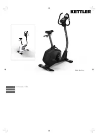
Exterior view of a Kettler ESR 2000 stationary exercise bike (no signage or text visible on body)IMPORTANT
PLEASE KEEP THIS BOOKLET FOR FUTURE REFERENCE. THIS IS IMPORTANT INFORMATION REGARDING THE USE AND CARE OF YOUR EXERCISE EQUIPMENT.
Safety Notice

Warning
This cross trainer has been designed and constructed to provide maximum safety. Nevertheless, certain precautions should be taken when using exercise equipment. Read the whole manual before assembling and using the cross trainer.
The following safety precautions should also be observed:
- It is the responsibility of the owner to ensure that all users of the cross trainer are adequately informed of all precautions. Use the cross trainer only as described in this manual.
- Keep children and pets away from this equipment at all times. DO NOT leave them unsupervised in the room where this cross trainer is kept.
- Inspect and assemble all parts regularly. Replace any worn parts immediately.
- Place the cross trainer on a level surface, with at least 1.0 ~m of clearance on each side. To protect the floor or carpet from damage, place a mat under the cross trainer.
- Keep the cross trainer indoors, away from moisture and dust. Keep in a ventilated environment.
- Don't put any sharp things around the cross trainer.
- Wear appropriate clothes while exercising; do not wear loose clothes that could become caught on the cross trainer. Always wear athletic shoes for foot protection while exercising.
• Maximum weight 150kg.
- Do not put your hands on the moving parts to prevent injuries.
- Keep pedaling speed controlled.
- If your cross trainer does not work as it should, discontinue use immediately.
- No more than one person should operate the cross trainer at one time.
- If you feel pain or dizziness while exercising, stop exercising immediately and consult a doctor.
Drawing for Assembly
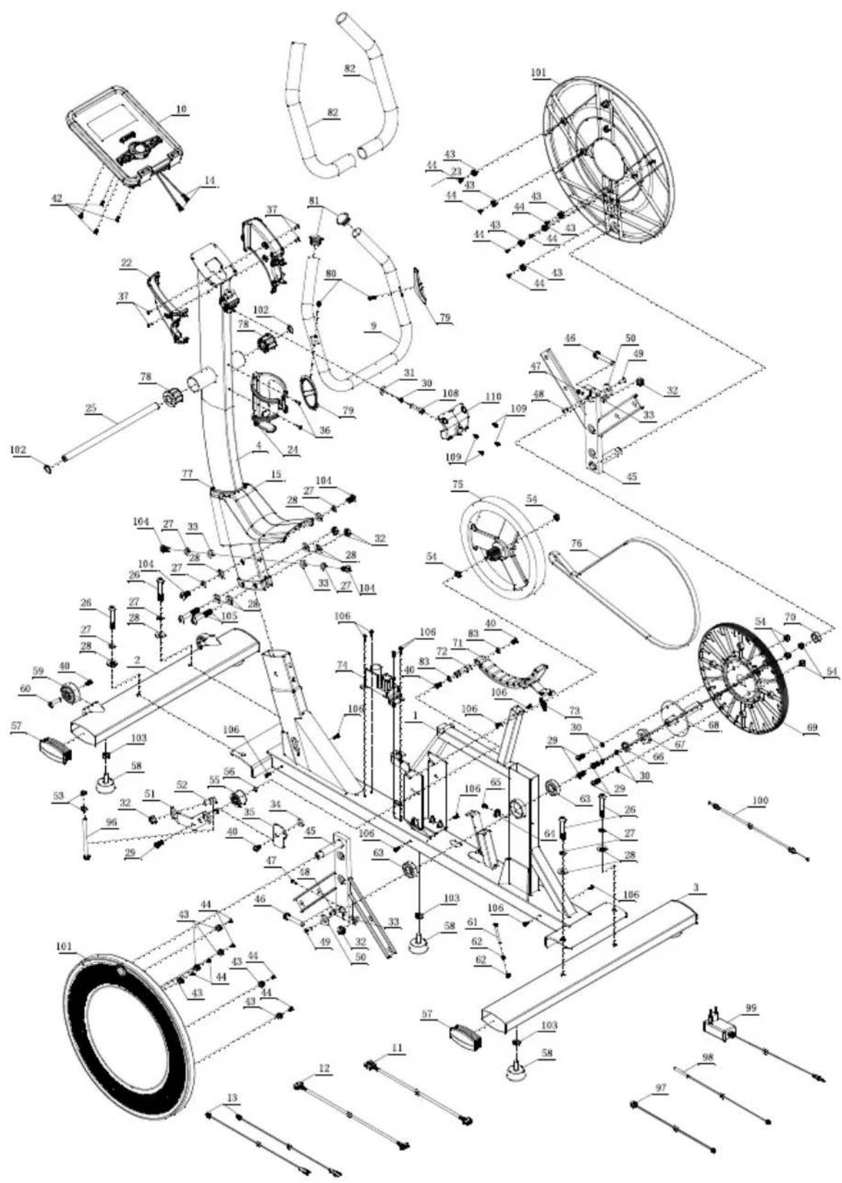
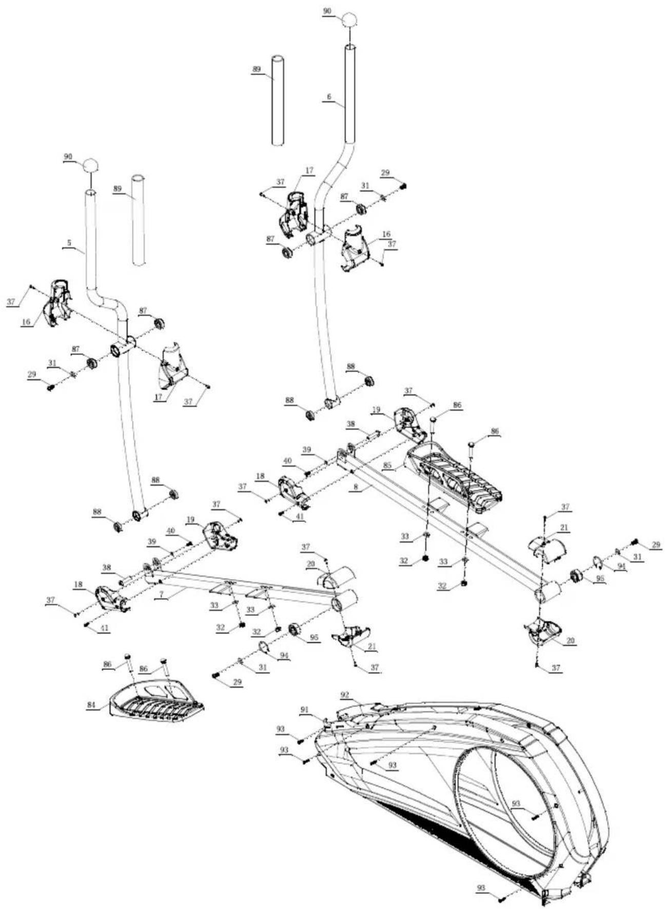
| No. Name Specification Quantity | |||
| 1 Main frame 1 | |||
| 2 Front stabiliser 1 | |||
| 3 Rear stabiliser 1 | |||
| 4 Upper Upright post 1 | |||
| 5 Body arm(L) 1 | |||
| 6 Body arm(R) | 1 | ||
| 7 | Pedal supporter(L) | 1 | |
| 8 | Pedal supporter(R) | 1 | |
| 9 Handlebars | 1 | ||
| 10 | Console | 1 | |
| 11 | Motor communication wire | 1 | |
| 12 | Console communication wire | 1 | |
| 13 | Handle pulse connection wire | 2 | |
| 14 | Console outset | 2 | |
| 15 | Upright post cover | 1 | |
| 16 | Body arm cover | 2 | |
| 17 | Body arm cover | 2 | |
| 18 | Front pedal supporter cover | 2 | |
| 19 | Front pedal supporter cover | 2 | |
| 20 | Rear pedal supporter cover | 2 | |
| 21 | Rear pedal supporter cover | 2 | |
| 22 | Handlebar cover(L) | 1 | |
| 23 | Handlebar cover(R) | 1 | |
| 24 | Bottle Holder | 1 | |
| 25 | Axle | 17 × 339.5 | 1 |
| 26 | Allen C.K.S. half thread screw | M10×60×25 | 4 |
| 27 | Spring washer | 10 | 8 |
| 28 | Curved washer | 10.5 × R100 × t2.0 | 10 |
| 29 | Allen C.K.S. Full thread screw | M8×20 | 9 |
| 30 | Spring washer | 8 | 5 |
| 31 | Flat washer | 8.5 ×,20 × t1.5 | 5 |
| 32 Hex | self-locking nut M10 5 | ||
| 33 Flat | washer ∅10 4 | ||
| 34 Idler | stopper 1 | ||
| 35 Idler | stopper 1 | ||
| 36 Philips pan head full thread screw | M4x16 2 | ||
| 37 Philips pan head full thread screw | M4x10 16 | ||
| 38 | Allen C.K.S. hollow screw | ∅ 10x45xM6x20 2 | |
| 39 Flat | washer ∅6 | 2 | |
| 40 | Allen C.K.S. hollow screw | M6x15 | 7 |
| 41 | Philips C.K.S. self-tapping screw | ST4x15 | 2 |
| 42 | Philips C.K.S. full head screw | M5x10 | 4 |
| 43 | Disc plastic buckle | ∅ 12.4x13 | 12 |
| 44 | Philips C.K.S. end-cutting self-tapping screw | ST4x10 | 12 |
| 45 | Crank iron | 2 | |
| 46 Hex | half thread screw M10x55x20 | 2 | |
| 47 Hex | half thread screw M4x12 | 2 | |
| 48 Flat | key 5x5x15 2 | ||
| 49 | Allen full thread screw | M6x15 | 2 |
| 50 Flat | washer ∅Bx∅30xt3.0 | 2 | |
| 51 | Fixed idler | 1 | |
| 52 Idler | connecting shaft ∅15x30 1 | ||
| 53 | Hex nut | M8 | 2 |
| 54 | Hex locking nut | M8 | 6 |
| 55 | Tension pulley | 1 | |
| 56 | Circlip shaft | ∅10 1 | |
| 57 | End cap | 4 | |
| 58 | Feet pad | 5 | |
| 59 Wheels | 2 | ||
| 60 | Allen C.K.S. hollow screw | ∅8x33xM6x15 | 2 |
| 61 | Hex full thread screw | M5x60 | 1 |
| 62 | Hex nut | M5 | 2 |
Parts List
| No. | Name Specification Quantity | ||
| 63 | Deep groove ball bearing 6004-2RS 2 | ||
| 64 | Fixed magnetic induction 1 | ||
| 65 | Philips washer head end-cutting self-tapping screw ST4-12 1 | ||
| 66 | Crank axle sleeve 1 1 | ||
| 67 | Crank axle sleeve 3 1 | ||
| 68 | Crank axle ∅20x115 1 | ||
| 69 | Belt pulley | ∅308x22 | 1 |
| 70 | Crank axle sleeve 2 1 | ||
| 71 | Fixed magnet set | 1 | |
| 72 | Magnetic control fixed axle ∅12x50 | 1 | |
| 73 | Brake tension spring | 1 | |
| 74 | Magnet motor | 1 | |
| 75 | Double way flywheel | ∅280/9KG 1 | |
| 76 | Motor belt | 540PJ6 1 | |
| 77 | Upright post decoration strip | 102x57x8 | 1 |
| 78 | Plastic cover | ∅42.5x30 | 2 |
| 79 | Handle pulse | 2 | |
| 80 | Philips C.K.S. self-tapping screw | ST4x20 | 2 |
| 81 | Pipe plug ∅28xt1 .5 2 | ||
| 82 | Foam grip | ∅32xt3.0x480 | 2 |
| 83 | Circlip for shaft ∅12 2 | ||
| 84 | Pedal(L) | 406x187x74 | 1 |
| 85 | Pedal(R) | 406x187x74 | 1 |
| 86 | Carriage bolt | M10x55x20 | 4 |
| 87 | Deep groove ball bearing 6003-2RS 4 | ||
| 88 | Deep groove ball bearing 6200-2RS 4 | ||
| 89 | Foam grip | ∅36xt3.0x720 | 2 |
| 90 | Pipe plug ∅32xt1 .5 2 | ||
| 91 | Chain cover (L) | 1291.1x72x616.2 | 1 |
| 92 | Chain cover (R) | 1291.1x75.9x616.2 | 1 |
| 93 | Philips C.K.S. Self-tapping screw | ST4x25 | 5 |
Parts List
| No. Name Specification Quantity | |||
| 94 Circ | ip for holes ∅40 2 | ||
| 95 Self | aligning ball bearing 2203-2RS 2 | ||
| 96 Hex | full thread screw M8x120 1 | ||
| 97 Power communication wire 1 | |||
| 98 | Magnetic sensor | 1 | |
| 99 | Power adapter | 1 | |
| 100 | Brake line | 1 | |
| 101 | Disc | ∅466.6x24.1 | 2 |
| 102 | Waved spring washer | ∅17 2 | |
| 103 | Hex nut | M10 | 5 |
| 104 Allen C.K.S. full head screw M10x20 4 | |||
| 105 | Allen C.K.S. half thread screw | M10x55x20 | 2 |
| 106 | Philips C.K.S. self-tapping screw | ST4x16 | 12 |
| 107 | Carriage bolt M10x55x20 | 4 | |
| 108 | Hexagon socket head full thread bolts M8x30 1 | ||
| 109 | Cross recessed large flat head tapping screws | ST4x12 | 4 |
| 110 Handle bar cover (front) | 1 | ||
Product Diagram
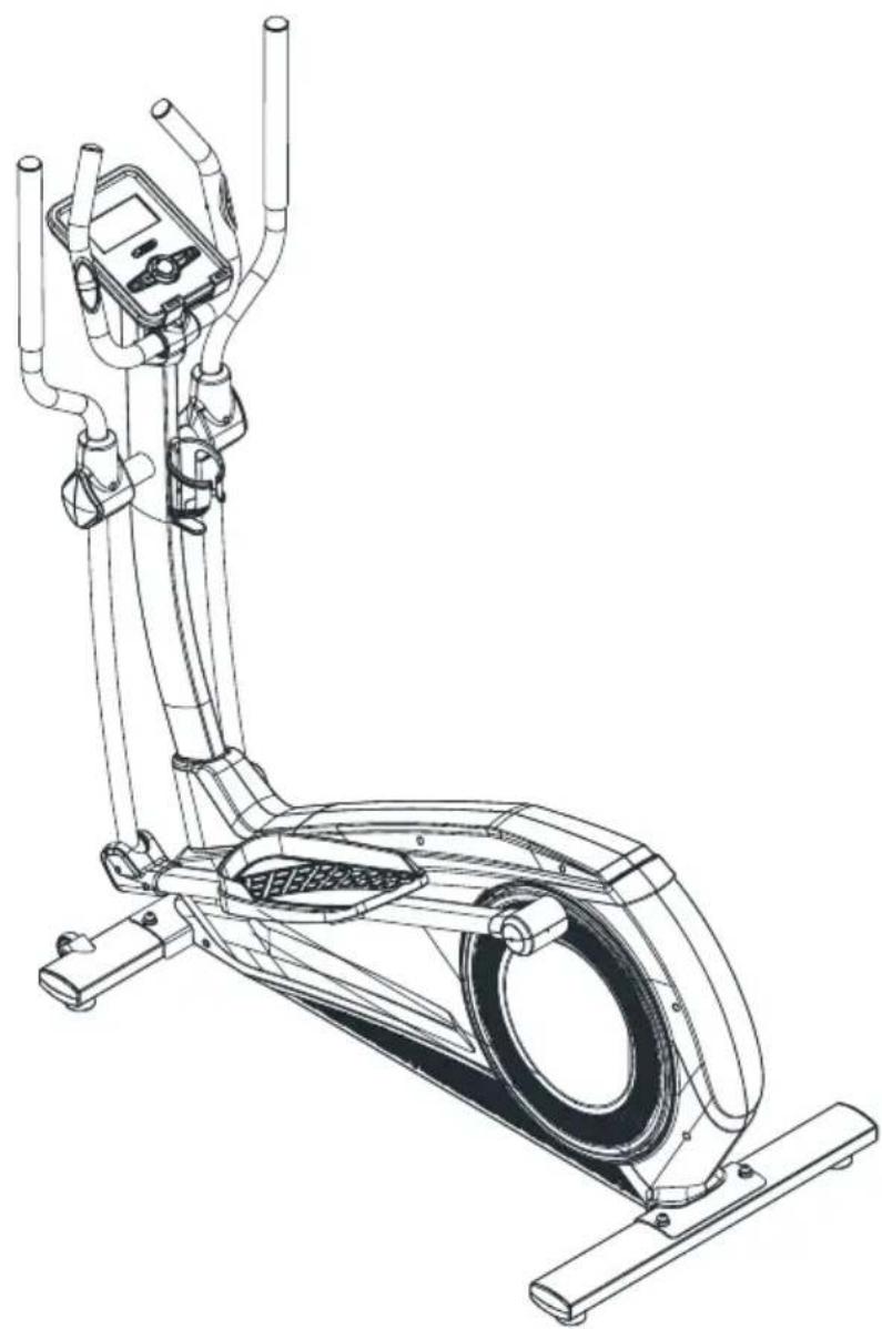
natural_image
Line drawing of an stationary exercise bike with visible components and suspension arms (no text or symbols)| Dimension 1620x720x1520mm | |
| Speed Ratio 9 | |
| Resistance Fragment 1-32 | |
| Stride Length 420x200 | |
Pre-assembly Notes
Open the boxes:
Make sure you check you have all of the parts listed in the box prior to assembly. If there are any parts missing, please contact the supplier.
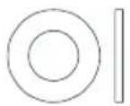
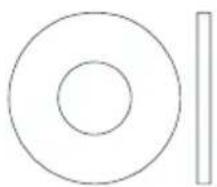
natural_image
Simple geometric diagram with concentric circles and a vertical line (no text or symbols)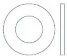
natural_image
Simple geometric diagram with concentric circles and a vertical line (no text or symbols)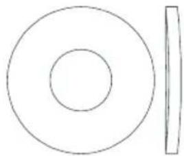
natural_image
Simple geometric diagram with concentric circles and a vertical line (no text or symbols)∅6 - Qty 2
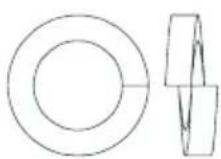
∅8.5 x ∅20 x T1.5 - Qty 5 ∅10 - Qty 6 ∅110.5 x R100 x T2.0 - Qty 10
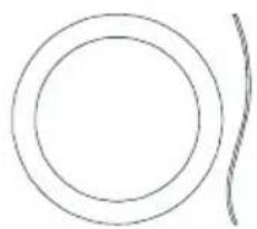
natural_image
Simple line drawing of two concentric circles with a separate curved line on the right (no text or symbols)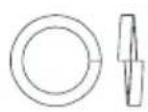
natural_image
Technical line drawing of a hexagonal nut and a separate hexagonal bolt (no text or symbols)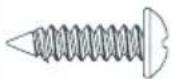
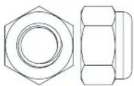
∅17 - Qty 2 ∅8 - Qty 2 ∅10 - Qty 8 M10 - Qty 2
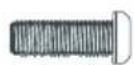
ST4 x 15
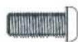
M4 x 10
- Qty 2
- Qty 16
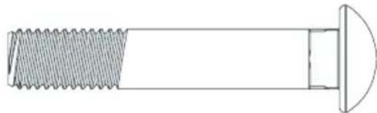
natural_image
Technical line drawing of a threaded bolt with a semicircular end cap (no text or symbols)M4 x 16
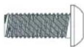
M6 × 15
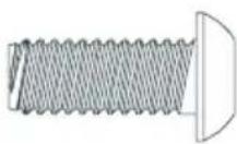
M8 x 20 - Qty 4
M10 x 55 - Qty 4
- Qty 2
- Qty 2
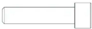
natural_image
Simple line drawing of a bolt or pin (no text or symbols)M8x30 - Qty 1
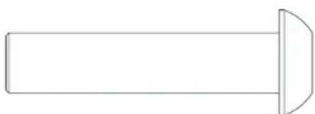
natural_image
Simple line drawing of a cylindrical object with a flanged end (no text or symbols)∅10 x 45 x M6 x 20 - Qty 2
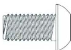
M10 x 20 - Qty 4
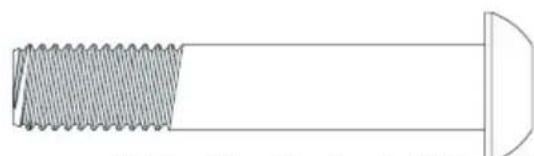
natural_image
Technical line drawing of a bolt with threaded shaft and flange (no text or symbols)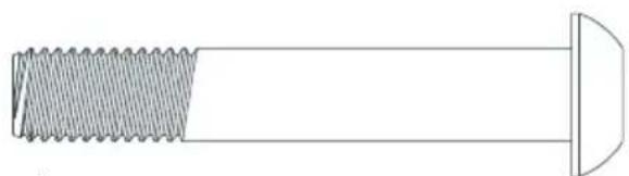
natural_image
Technical line drawing of a mechanical component with threaded shaft and curved base (no text or symbols)M10 x 55 x 20 - Qty 2 M10 x 60 x 25 - Qty 4
Parts List - Hardware Bag
| No. Name Specification Quantity | |||
| 26 Allen C.K.S. half thread screw M10x60x25 4 | |||
| 27 Spring washer ∅10 12 | |||
| 28 Curved washer ∅10.5xR100xt2.0 10 | |||
| 29 Allen C.K.S. half thread screw M8x20 4 | |||
| 30 Spring washer ∅8 1 | |||
| 31 | Flat washer | ∅ 8.5x∅20xt1.5 | 5 |
| 32 | Hex locking nut M10 | 2 | |
| 33 | Flat washer | ∅10 | 6 |
| 36 | Philips pan head full thread screw | M4x16 | 2 |
| 37 | Philips pan head full thread screw | M4x10 | 16 |
| 38 | Allen C.K.S. hollow screw | ∅1 0x45xM6x20 | 2 |
| 39 | Flat washer | ∅6 | 2 |
| 40 | Allen C.K.S. full thread screw | M6x15 2 | |
| 41 | Philips C.K.S. self-taping screw | ST4x16 | 2 |
| 102 | Waved spring washer | ∅17 | 2 |
| 104 | Allen full thread screw | M10x20 | 4 |
| 105 | Allen C.K.S. half thread screw | M10x55x20 2 | |
| 107 Carriage bolt M10x55x20 4 | |||
| 108 | Hexagon socket head full thread bolts | M8x30 1 | |
| 109 | Cross Recessed large flat head tapping screws | ST4x12 | 4 |
Gather Your Tools
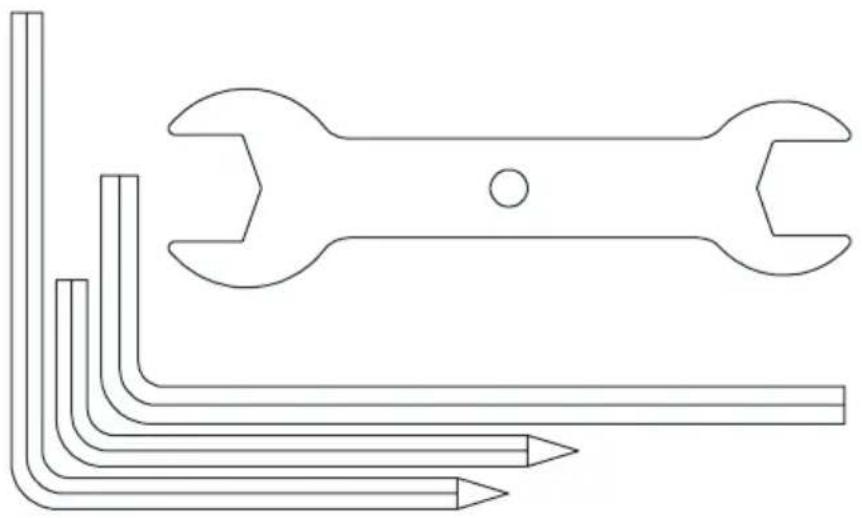
Before starting assembly ensure you have the correct tools.
natural_image
Line drawing of a wrench and pencil tool (no text or symbols)| Name Specification Quantity | |
| L-shaped wrench 5x80x80S 1 | |
| L-shaped wrench 5x35x85S 1 | |
| L-shaped wrench 6x40x120 1 | |
| Open-end wrench 15#&17# 1 |
Clear your work area
Make sure that you have cleared away a large enough space to properly assemble the unit. Make sure the space is free from anything that may cause injury during assembly. After the unit is fully assembled make sure there is a comfortable amount of free area around the unit for unobstructed operation.
NOTE: Follow the instructions step by step. Read and understand all instructions thoroughly before assembly.
Assembly Instructions
1
Step 1:
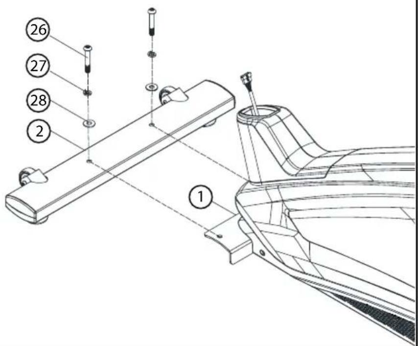
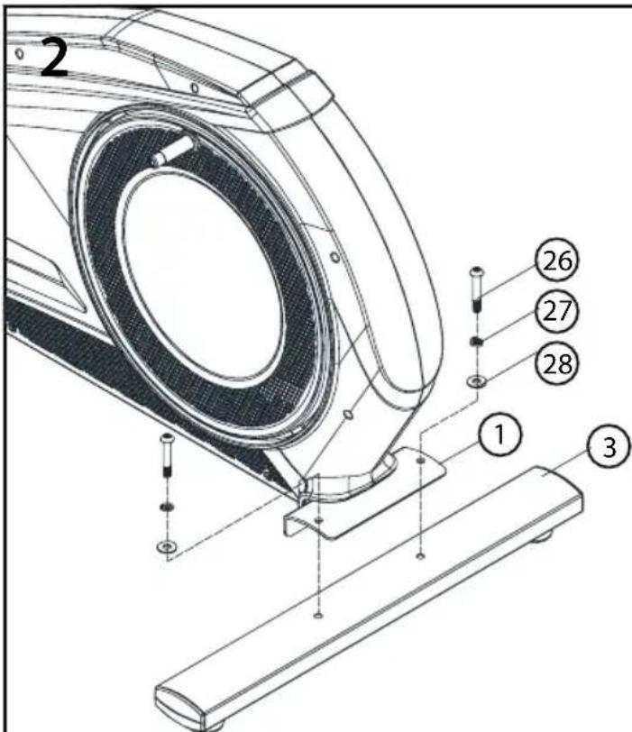
Attach the front stabiliser (2) to the main frame (1) with curved washer (28), spring washer (27) and Allen C.K.S. half thread screw (26).
Step 2:
Attach the rear stabiliser (3) to the main frame (1) with curved washer (28), spring washer (27) and Allen C.K.S. half thread screw (26).
Assembly Instructions
3
Step 3:
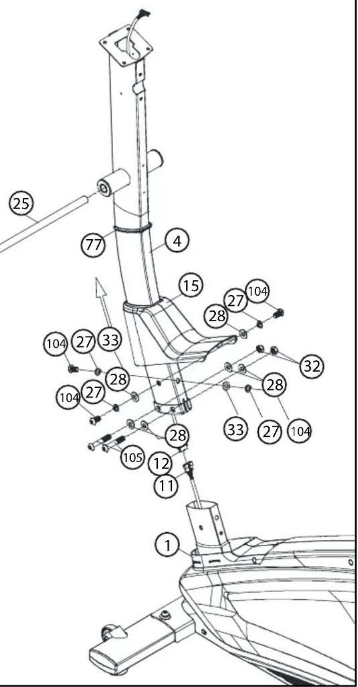
- Attach upright post decoration strip (77) to the upper upright post (4). Take the upright post cover (15) from the main frame (1). Then attach to the upper upright post (4).
- Connect motor communication wire (11) and console communication wire (12).
- Attach upper upright post (4) to the main frame (1) with flat washer (33), spring washer (27), Allen C.K.S. full thread screw (104) and Allen C.K.S. half thread screw (105), curved washer (28), spring washer (27), hex self-locking nut (32).
- Attach upright post cover (15) and upright post decoration strip (77) to the main frame (1). Then install the Axle (25).
Tip:
Put the wires in the upright post to prevent folding after connecting all of wires.
Do not fully tighten the Bolt yet. Make sure that all screws are in the hexagonal hole.
Assembly Instructions
Step 4:
-
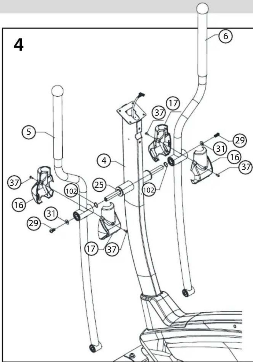
Assemble the waved spring washers (102) to the left and right Axle (25). Lubricate both ends of the Axle (25). Then attach left body arm (5) and right body arm (6) to the left Axle (25) and rightAxle (25) with flat washer (31) and Allen C.K.S. full thread screw (29).
-
Attach arm cover (16/17) to the left body arm (5) with Philips pan head full thread screw (37).
-
Repeat the last step to attach cover (16/17) to the right body arm (6).
Step 5:
-
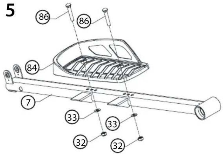
Install the foot pedal left (84) on the pedal group left (7), and lock it with carriage screw (86), flat washer (33) hexagon lock nut (32).
-
Install the foot pedal to the right (85) of the pedal group - right (8) in the same way.
Assembly Instructions
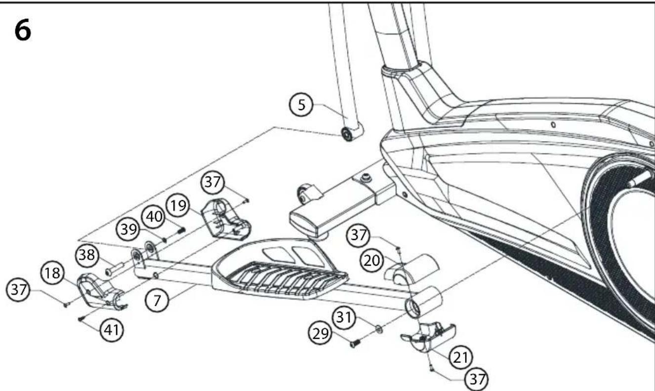
Step 6:
- Lubricate the axle of the main frame (1). Attach the axle sleeve of left rear pedal supporter (7) to the axle of main frame (1) with flat washer (31) and Allen C.K.S. full thread screw (29).
- Attach the axle sleeve of left front pedal supporter (7) to left body arm (5) with Allen C.K.S. hollow screw (38), flat washer (39) and Allen C.K.S. full thread screw (40).
- Attach the rear cover of pedal supporter (20/21) to left pedal supporter (7) with Philips pan head full thread screw (37). Attach the front cover of pedal supporter (18/19) to left pedal supporter (7) with Philips pan head full thread screw (37) and Philips C.K.S. self-tapping screw (41).
- Install right pedal supporter (8) with the same way. Put the back side of the pedal supporter (R) (8) on the axle of the main frame (1), use the flat washer (31) and Allen full thread screw (29) to fix it.
7
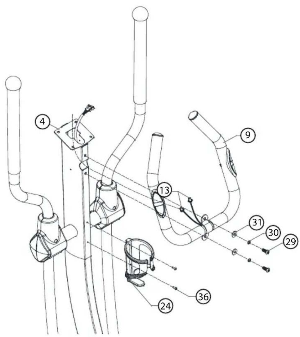
Step 7
-
Through handle pulse connection wire (13) out of the upper upright post (4). Attach handlebars (9) to upright post (4) with flat washer (31), spring washer (30) and Philips pan head full thread screw (36).
-
Attach bottle holder (24) to upper upright post (4) with Philips pan head full thread screw (36).
Assembly Instructions
8
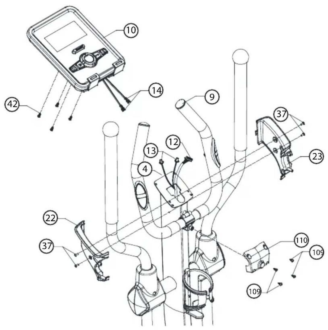
Step 8
- Connect console communication wire (12) with the interface of back console. Connect handle pulse communication wire (13) with console outset (14).
- Attach console (10) to upper upright post (4) with Philips C.K.S. full thread screw (42).
- Through left handlebar cover (22) and right handlebar cover (23) out of the handlebar (9). Attach them to the upper upright post (4) with Philips pan head full thread screw (37).
natural_image
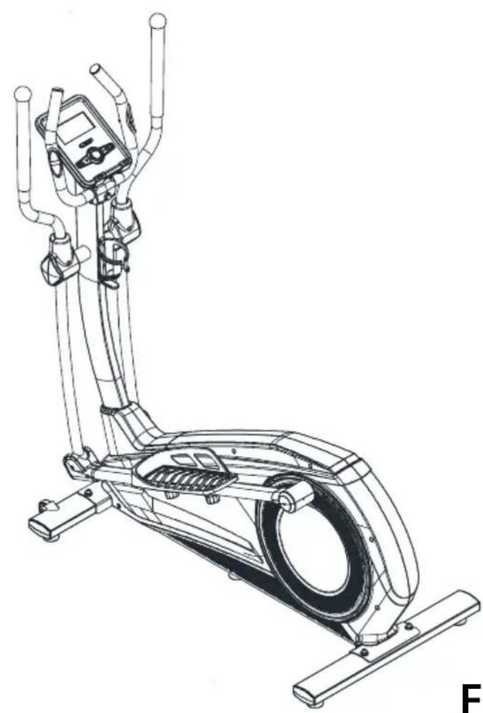
Line drawing of a stationary exercise bike with control panel and leg support (no text or symbols)Finished.

Workout Tips
- The user is required to put their feet completely inside the pedal.
- Adjust the magnetic resistance to the user.
- When ending the workout, reduce the resistance and gently slow down the pedalling action until stationary.
Half-Drawing for Assembly
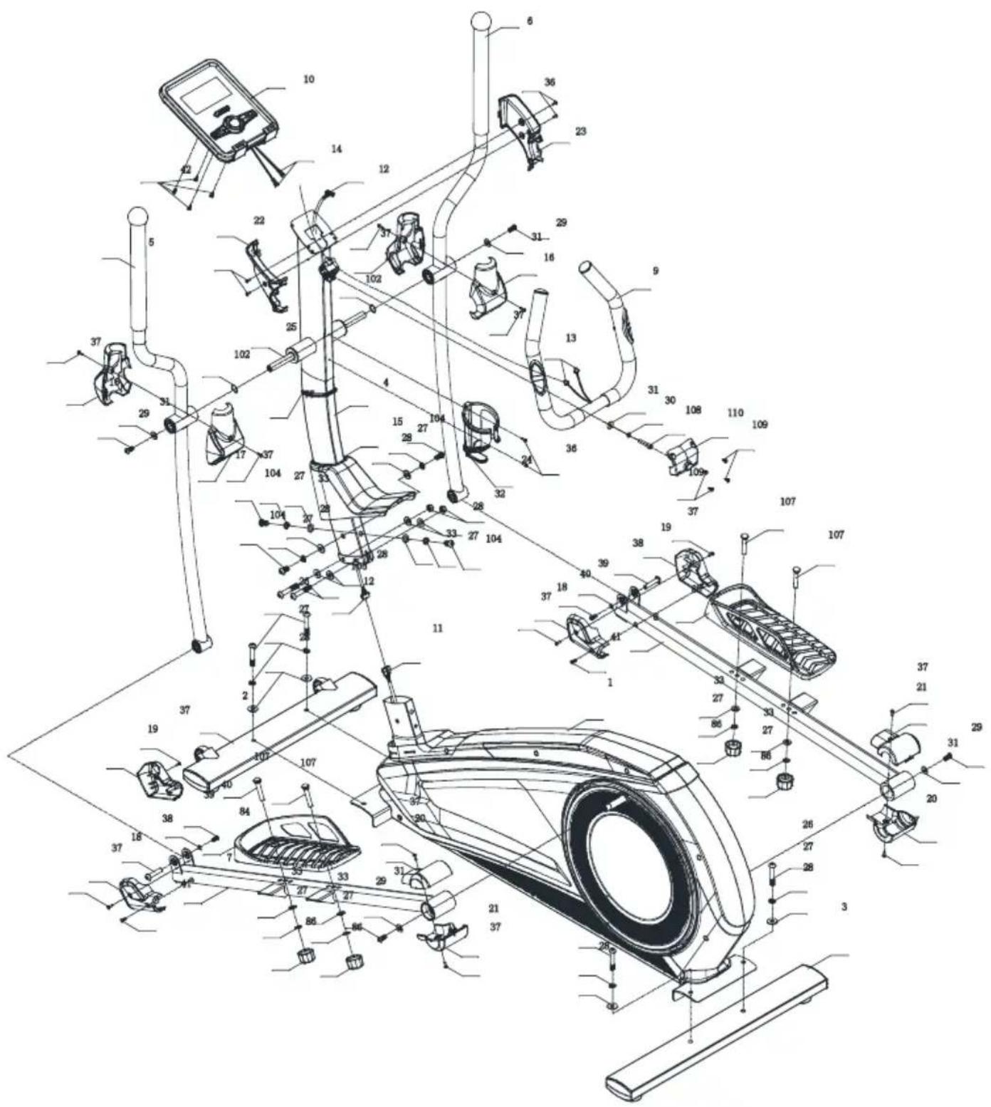
| No. Name Specification Quantity | |||
| 1 Main frame 1 | |||
| 2 Front stabiliser 1 | |||
| 3 Rear stabiliser 1 | |||
| 4 Upper Upright post 1 | |||
| 5 Body arm(L) 1 | |||
| 6 Body arm(R) | 1 | ||
| 7 | Pedal supporter(L) | 1 | |
| 8 | Pedal supporter(R) | 1 | |
| 9 Handlebars | 1 | ||
| 10 | Console | 1 | |
| 11 | Motor communication wire | 1 | |
| 12 | Console communication wire | 1 | |
| 13 | Handle pulse connection wire | 2 | |
| 14 | Console outset | 2 | |
| 15 | Upright post cover | 1 | |
| 16 | Body arm cover | 2 | |
| 17 | Body arm cover | 2 | |
| 18 | Front pedal supporter cover | 2 | |
| 19 | Front pedal supporter cover | 2 | |
| 20 | Rear pedal supporter cover | 2 | |
| 21 | Rear pedal supporter cover | 2 | |
| 22 | Handlebar cover(L) | 1 | |
| 23 | Handlebar cover(R) | 1 | |
| 24 | Bottle Holder | 1 | |
| 25 | Axle | 17 × 339.5 | 1 |
| 26 | Allen C.K.S. half thread screw | M10×60×25 | 4 |
| 27 | Spring washer | 10 | 12 |
| 28 | Curved washer | 10.5 × R100 × t2.0 | 10 |
| 29 | Allen C.K.S. Full thread screw | M8×20 | 4 |
| 30 | Spring washer | 8 | 1 |
| 31 | Flat washer | 8.5 ×,20 × t1.5 | 5 |
Parts List
| No. Name Specification Quantity | |||
| 32 Hex | self-locking nut M10 2 | ||
| 33 Flat | washer ∅10 6 | ||
| 36 Philips pan head full thread screw M4x16 2 | |||
| 37 Philips pan head full thread screw M4x10 16 | |||
| 38 | Allen C.K.S. full thread screw | ∅ 10x45xM6x20 | 2 |
| 39 Flat | washer ∅6 | 2 | |
| 40 | Allen C.K.S. hollow screw | M6x15 2 | |
| 41 | Philips C.K.S. self-tapping screw | ST4x15 | 2 |
| 42 | Philips C.K.S. full head screw | M5x10 4 | |
| 84 | Pedal (L) | 406×187×74 | 1 |
| 85 | Pedal (R) | 406×187×74 | 1 |
| 86 | Carriage bolt | M10x55x20 | 4 |
| 102 | Waved spring washer | ∅17 2 | |
| 104 | Allen C.K.S. full head screw | M10×20 | 4 |
| 105 | Allen C.K.S. half thread screw | M10x55x20 | 2 |
| 107 | Carriage bolt | M10x55x20 | 4 |
| 108 | Hexagon socket head full thread bolts | M8x30 1 | |
| 109 | Cross Recessed large flat head tapping screws | ST4x12 | 4 |
| 110 | Handle bar cover (front) | 1 | |
Display Functions
| Item Description | |
| Time Display Range | 0:00 ~ 99:59; Setting range 0:00 ~ 99:00 |
| Speed Range 0.0 ~ 99.9KM/H | |
| Distance Display Range | 0.0 ~ 99.99; Setting range 0.0 ~99.90 |
| Calories Display Range | 0 ~ 9999 Cal; Settingrange 0 ~ 9990 Cal |
| Pulse Display Range | P-30 ~230; Setting range 0-30 ~230 |
| RPM Range 0 ~ 999 | |
| Watt Display Range | 0 ~ 999; Setting Range 10 ~ 350 |
Keys
| Item Description | |
| Up(+) Select function or increase resistance level | |
| Down(-) Select function or decrease resistance level | |
| Enter In STOP mode, press it to confirm setting or selection | |
| Reset | Hold on pressing for 2 seconds, computer will reboot and start from user settingReverse to main menu during presetting workout value or in stop mode |
| Start/Stop Start or Stop workout | |
| Recovery Test heart rate recovery status | |
| Body Fat | Test body fat% and BMI |
Operation
POWER ON
Plug in power supply, computer will power on with a long beep sound and display all segments on LCD for 2 seconds(Drawing 1). Enter into user selection (Drawing 2) and persona! data setting mode (Age, Gender, Height, Weight).
After 4 minutes without pedaling or pulse input, console will enter into power saving mode.
Press any key may wake the console up.
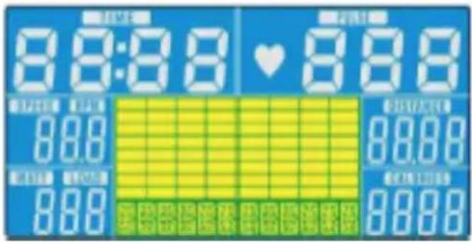
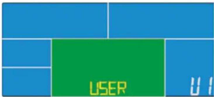
Drawing 1 Drawing 2
Personal Data Setting
After selecting user from U1\~U4, press ENTER to confirm. Press UP(+) or DOWN (-) to set SEX, AGE (Drawing 3), HEIGHT, WEIGHT and confirm by pressing ENTER. All data will be saved as user profile.
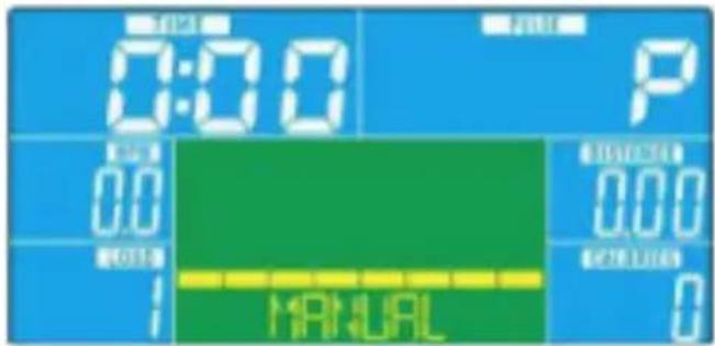
After setting, console go to main menu and display as Drawing 4. In this page, user can start workout directly by pressing START/STOP button.
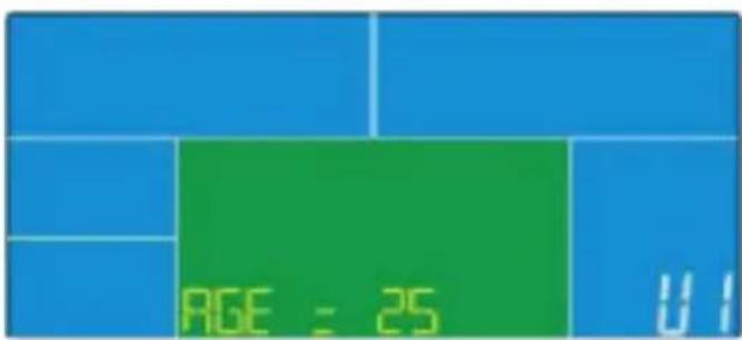
Drawing 3
Drawing 4
Operation
Workout Selection
In main page, the first program MANUAL is flashing (Drawing 5). User can press UP(+) or DOWN(-) to select: MANUAL-->PROGRAM-->USER PROGRAM-->H.R.C.-->WATT, press ENTER to confirm.
Manual Mode
- Press UP(+) or DOWN(-) to select workout program, choose Manual (Drawing 4) and press ENTER key to confirm.
- Press UP(+) or DOWN(-) to preset value of TIME/DISTANCE/CALORIES/PULSE and press ENTER to confirm.
- Press START/STOP keys to start workout. During workout, user can press UP and DOWN to adjust load level from 1 \~16.
- Press START/STOP keys to pause workout. Press RESET to reverse to main menu.
Program Mode
- Press UP(+) or DOWN(-) to select workout program, choose Program (Drawing 5) and press ENTER key to confirm.
- Press UP(+) or DOWN(-) to select program from P01\~P12, the program profile will display by turn.
- Press UP(+) or DOWN(-) to preset workout TIME.
- Press START/STOP keys to start workout. During workout, user can press UP(+) or DOWN(-) to adjust load level from 1\~16.
- Press START/STOP keys to pause workout. Press RESET to reverse to main menu.
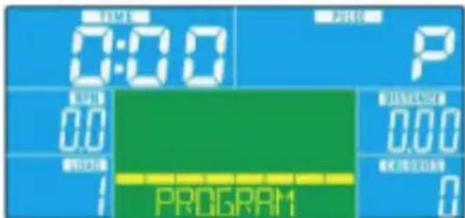
Drawing 5
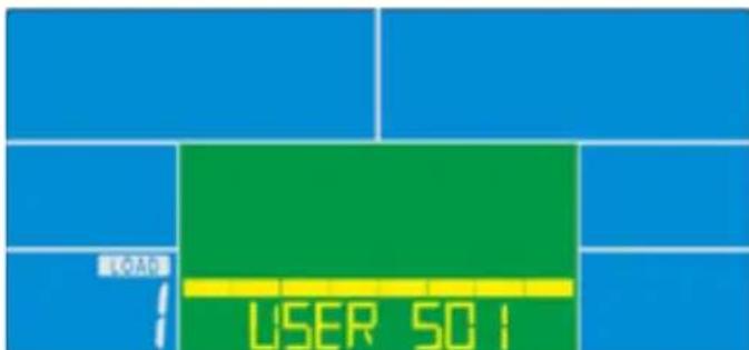
Drawing 6
Operation
H.R.C Mode
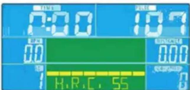
- Press UP(+) or DOWN(-) to select workout program, choose H.R.C. (Drawing 7) and press ENTER key to confirm.
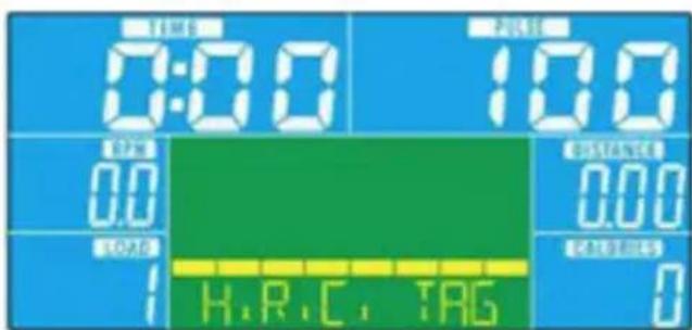
- Press UP(+) or DOWN(-) to select: H.R.C 55 (Drawing 8), H.R.C75, H.R.C 90 or TAG (TARGET H.R.) (default: 100, Drawing 9) and confirm by pressing ENTER.
- When select H.R.C 55, H.R.C75, H.R.C 90, console will display preset target value according to user age. Press UP(+) or DOWN(-) and ENTER to preset workout TIME.
- When select TAG H.R., the preset value 100 is flashing as Drawing 9. Press UP(+) or DOWN(-) to adjust value from 30\~230 and confirm by ENTER. Preset workout TIME by pressing UP(+) and DOWN(-).
- Press START/STOP button to start or stop workout. Press RESET to reverse to main menu.
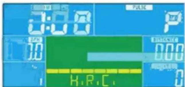
Drawing 7 Drawing 8
Drawing 9
Operation
Watt Mode
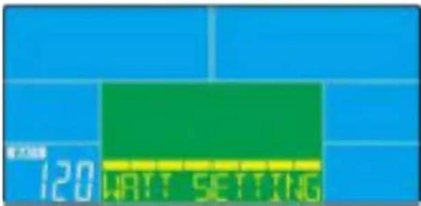
- Press UP(+) or DOWN(-) to select workout program, choose WATT (Drawing 10) and press ENTER key to confirm.
- Press UP(+) or DOWN(-) to preset WATT target. (default: 120)
- Press UP(+) or DOWN(-) to preset workout TIME.
- Press START/STOP button to start workout. During workout, user can press UP(+) or DOWN(-) to adjust WATT level from 10-350.
- Press START/STOP button to pause workout. Press RESET to reverse to main menu.
Drawing 10
Body Fat Mode
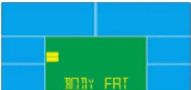
- During workout, press START/STOP to stop workout, press BODY FAT key to start measure. (Drawing 11)
- Hold on hand grips, after 8 seconds, computer will show BMI, FAT% and fat symbol.
- Press BODY FAT key again reverse to main menu.
- Error code:
* Console display E-1 (Drawing 12): user is not holding hand grips correctly.
* Console display E-4 (Drawing 13): FAT% exceed setting range (5.0% -50.0%)
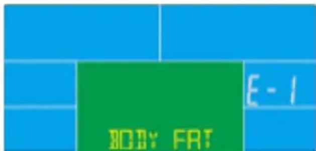
Drawing 11 Drawing 12
Operation
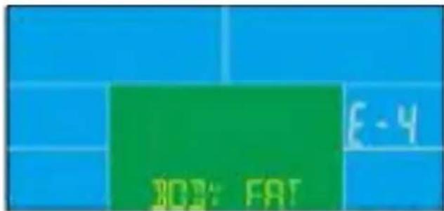
Drawing 13
BMI (Body Mass Index) integrated
| BMI LOW LOW/MED MEDIUM MED/HIGH | ||||
| Scale | ||||
| Range <20 20>24 24.1-26.5 >26.5 | ||||
Body Fat:
| Symbol LOW | LOW/MED MEDIUM | MED/HIGH | ||
| Fat% | ||||
| Male <13% | 13%-25.9% 26%-30% | >30% | ||
| Female <23% | 23%-35.9% 36%-40% | >40% |
Recovery
- When pulse value display on the computer (hold hand grips), press RECOVERY button.
- All function display will stop except TIME" starts counting down from 00:60 to 00:00 (Drawing 14). When TIME counts down to 0, screen will display your heart rate recovery status with the FX (X=1\~6, Drawing 15). F1 is the best, F6 is the worst. (See below chart) (Press the RECOVERY button again to return the main display.)
- During RECOVERY, user may press RECOVERY button to back to main menu.
- Without pulse inputted, it is invalid to press RECOVERY button.
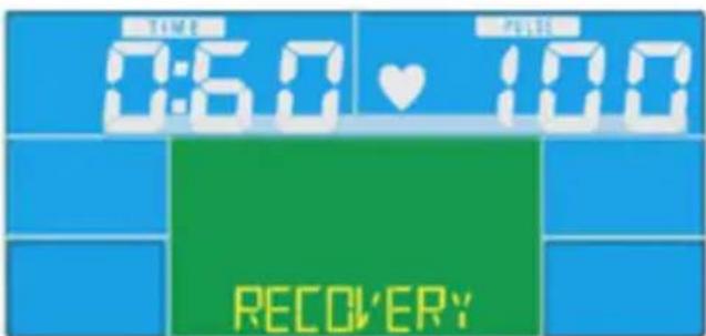
Drawing 14
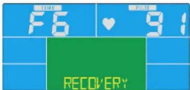
Drawing 14
Operation
BMI (Body Mass Index) integrated
| 1.0 Outstanding | |
| 1.0 < F < 2.0 Excellent | |
| 2.0 < F < 2.9 Good | |
| 3.0 < F < 3.9 Fair | |
| 4.0 < F < 5.9 Below Average | |
| 6.0 Poor | |
Note:
- This computer require 9V, 1300mA adaptor.
- When user stop pedaling for 4 minutes, computer will enter into power saving mode, all setting and exercise data will stored until user start exercise again.
- If you experience problems with the computer, remove the adaptor and plug back in. This should resolve the issue.
For Your Safety
- Check all components regularly for correct function, damage and loose connections especially at the start of the season and at 1-2 month intervals dependent on use.
- Kettler will not be responsible for damaged caused by improper use.
- Damaged components may endanger your safety or shorten the life of the product. Replace all damaged parts immediately. Use only spare parts manufactured by Kettler.

For further information and spare parts visit our website www.kettler.co.uk/shop

Attention
- Whilst assembling this product keep out of the reach of children. (Choking hazard – contains small parts)
- Ensure that your working area is free of possible sources of danger, for example don't leave any tools lying around.
- Always dispose of packaging material in such a way that it may not cause any danger. There is always a risk of suffocation if children play with plastic bags!
• We reserve the right to make changes for technical reasons.
KETTLER

www.kettler.co.uk

Warranty For Home Use
This product is covered by a 3 year warranty against manufacturing faults. This warranty applies to domestic use only. It does not cover commercial use, mis-use or accidental damage.
To validate your warranty, register at www.kettler.co.uk and quote the product code from the front of this booklet.

- IMPORTANT
- Safety Notice
- Warning
- The following safety precautions should also be observed:
- Drawing for Assembly
- Parts List
- Product Diagram
- Pre-assembly Notes
- Open the boxes:
- Parts List - Hardware Bag
- Gather Your Tools
- Clear your work area
- Assembly Instructions
- 1
- Step 1:
- Step 2:
- 3
- Step 3:
- Tip:
- Step 4:
- Step 5:
- Step 6:
- Step 7
- Step 8
- Workout Tips
- Half-Drawing for Assembly
- Display Functions
- Operation
- POWER ON
- Personal Data Setting
- Workout Selection
- Manual Mode
- Program Mode
- H.R.C Mode
- Watt Mode
- Body Fat Mode
- Recovery
- Note:
- For Your Safety
- Attention
- KETTLER
- Warranty For Home Use
Brand : KETTLER
Model : CTR 300
Category : Exercise bike