
NetBackup Flex 5340 - Server VERITAS - Free user manual and instructions
Find the device manual for free NetBackup Flex 5340 VERITAS in PDF.


| Type de produit | Serveur de sauvegarde / Appliance de sauvegarde |
| Marque | Veritas |
| Modèle | NetBackup Flex 5340 |
| Format de châssis | 2U rackmount |
| Dimensions (L x P x H) | 48,26 cm x 73,66 cm x 8,89 cm (19" x 29" x 3,5") |
| Poids maximal configuré | 32 kg (70 lb) |
| Unités d'alimentation | Alimentations redondantes, 1600 W chacune |
| Capacité de stockage | Jusqu'à 240 To (brut) avec disques SAS |
| Processeurs | Intel Xeon Silver ou Gold (selon configuration) |
| Mémoire RAM | 256 Go DDR4 ECC (extensible) |
| Interfaces réseau | 4 ports 10GbE SFP+, 4 ports 1GbE RJ45 |
| Fonctions principales | Sauvegarde, déduplication, réplication, récupération |
| Logiciel inclus | Veritas NetBackup, NetBackup Flex Appliance Manager |
| Entretien et nettoyage | Nettoyer l'extérieur avec un chiffon doux sec. Vérifier les filtres à air tous les 3 mois. |
| Sécurité | Verrouillage du châssis, fonctions de sécurité intégrées, mise à la terre requise |
| Pièces détachées et réparabilité | Disques, blocs d'alimentation, ventilateurs remplaçables à chaud. Processeur et mémoire remplaçables par un technicien. |
| Informations générales | Garantie d'un an avec extension possible. Support technique Veritas. |
Frequently Asked Questions - NetBackup Flex 5340 VERITAS
User questions about NetBackup Flex 5340 VERITAS
0 question about this device. Answer the ones you know or ask your own.
Ask a new question about this device
Download the instructions for your Server in PDF format for free! Find your manual NetBackup Flex 5340 - VERITAS and take your electronic device back in hand. On this page are published all the documents necessary for the use of your device. NetBackup Flex 5340 by VERITAS.
USER MANUAL NetBackup Flex 5340 VERITAS
Veritas 5340 Appliance Product Description
NetBackup™ 5340 Appliance
Flex™ 5340 Appliance
Veritas 5340 Appliance Product Description
Legal Notice
Copyright © 2018 Veritas Technologies LLC. All rights reserved.
Veritas, the Veritas Logo, Velocity, and NetBackup are trademarks or registered trademarks of Veritas Technologies LLC or its affiliates in the U.S. and other countries. Other names may be trademarks of their respective owners.
This product may contain third-party software for which Veritas is required to provide attribution to the third party (“Third-party Programs”). Some of the Third-party Programs are available under open source or free software licenses. The License Agreement accompanying the Software does not alter any rights or obligations you may have under those open source or free software licenses. Refer to the Third-party Legal Notices document accompanying this Veritas product or available at:
https://www.veritas.com/about/legal/license-agreements
The product described in this document is distributed under licenses restricting its use, copying, distribution, and decompilation/reverse engineering. No part of this document may be reproduced in any form by any means without prior written authorization of Veritas Technologies LLC and its licensors, if any.
THE DOCUMENTATION IS PROVIDED "AS IS" AND ALL EXPRESS OR IMPLIED CONDITIONS, REPRESENTATIONS AND WARRANTIES, INCLUDING ANY IMPLIED WARRANTY OF MERCHANTABILITY, FITNESS FOR A PARTICULAR PURPOSE OR NON-INFRINGEMENT, ARE DISCLAIMED, EXCEPT TO THE EXTENT THAT SUCH DISCLAIMERS ARE HELD TO BE LEGALLY INVALID. VERITAS TECHNOLOGIES LLC SHALL NOT BE LIABLE FOR INCIDENTAL OR CONSEQUENTIAL DAMAGES IN CONNECTION WITH THE FURNISHING, PERFORMANCE, OR USE OF THIS DOCUMENTATION. THE INFORMATION CONTAINED IN THIS DOCUMENTATION IS SUBJECT TO CHANGE WITHOUT NOTICE.
The Licensed Software and Documentation are deemed to be commercial computer software as defined in FAR 12.212 and subject to restricted rights as defined in FAR Section 52.227-19 "Commercial Computer Software - Restricted Rights" and DFARS 227.7202, et seq. "Commercial Computer Software and Commercial Computer Software Documentation," as applicable, and any successor regulations, whether delivered by Veritas as on premises or hosted services. Any use, modification, reproduction release, performance, display or disclosure of the Licensed Software and Documentation by the U.S. Government shall be solely in accordance with the terms of this Agreement.
Veritas Technologies LLC
500 E Middlefield Road
Mountain View, CA 94043
http://www.veritas.com
Technical Support
Technical Support maintains support centers globally. All support services will be delivered in accordance with your support agreement and the then-current enterprise technical support policies. For information about our support offerings and how to contact Technical Support, visit our website:
https://www.veritas.com/support
You can manage your Veritas account information at the following URL:
https://my.veritas.com
If you have questions regarding an existing support agreement, please email the support agreement administration team for your region as follows:
CustomerCare@veritas.comWorldwide (except Japan)
CustomerCare_Japan@veritas.comJapan
Documentation
Make sure that you have the current version of the documentation. Each document displays the date of the last update on page 2. The latest documentation is available on the Veritas website:
https://sort.veritas.com/documents
Documentation feedback
Your feedback is important to us. Suggest improvements or report errors or omissions to the documentation. Include the document title, document version, chapter title, and section title of the text on which you are reporting. Send feedback to:
NB.doc@veritas.com
You can also see documentation information or ask a question on the Veritas community site:
http://www.veritas.com/community/
Veritas Services and Operations Readiness Tools (SORT)
Veritas Services and Operations Readiness Tools (SORT) is a website that provides information and tools to automate and simplify certain time-consuming administrative tasks. Depending on the product, SORT helps you prepare for installations and upgrades, identify risks in your datacenters, and improve operational efficiency. To see what services and tools SORT provides for your product, see the data sheet:
https://sort.veritas.com/data/support/SORT_Data_Sheet.pdf
Chapter 1 About the Veritas 5340 Appliance .... 6
About the Veritas 5340 Appliance 6
Features and components of the appliance 7
Locating the appliance serial number 12
About 5340 Appliance compute node disk drive configurations ..... 12
About the 5340 Appliance compute node disk drive LEDs 14
About the 5340 Appliance compute node front panel USB port .... 15
About the 5340 Appliance control panel 15
About the System Status LED states 17
About the Power button LED states 20
About the appliance compute node rear panel 21
Available 5340 Appliance PCIe-based I/O configurations 24
Total 5340 Appliance on-board and PCIe-based I/O ports ...... 26
5340 Appliance on-board network interface port locations and speeds 33
Chapter 2 About the Veritas 5U84 Storage Shelves ...... 36
About Veritas 5340 Appliance storage shelves 37
Available appliance storage options 38
About the Veritas 5U84 Storage Shelf disk drive drawers 41
5U84 Primary Storage Shelf and the 5U84 Expansion Storage Shelf control panel .... 52
About the 5U84 Primary Storage Shelf and 5U84 Expansion Storage Shelf rear components .... 53
Veritas 5U84 Primary Storage Shelf RAID Controllers .... 56
Veritas 5U84 Expansion Storage Shelf Expansion I/O modules 60
Veritas 5U84 Storage Shelf cooling modules 63
5U84 Storage Shelf Power Supply Units 64
Chapter 3 Veritas 5340 Appliance and 5U84 Storage Shelf cables 66
Power cables 66
Network cable 68
Multi-mode fiber optic cable 69
SAS3 cable 70
Twinaxial copper cables 71
Appendix A Technical specifications, Environmental/Protocol standards, and Compliance standards 73
Flex 5340 Appliance compute node technical specifications .... 74
Veritas 5U84 Storage Shelf technical specifications 77
Environmental specifications 79
Protocol standards 80
Regulatory, compliance, and certification information 81
Product regulatory compliance 81
Product safety compliance 82
Product EMC Compliance - Class A Compliance 82
Product ecology compliance 83
Certifications / Registrations / Declarations 83
Electromagnetic compatibility notices 84
Index 86
About the Veritas 5340 Appliance
This chapter includes the following topics:
■ About the Veritas 5340 Appliance
■ Features and components of the appliance
■ Locating the appliance serial number
■ About 5340 Appliance compute node disk drive configurations
■ About the 5340 Appliance compute node front panel USB port
■ About the 5340 Appliance control panel
■ About the appliance compute node rear panel
About the Veritas 5340 Appliance
The Veritas 5340 Appliance supports the following software:
■ Flex Appliance software release
■ NetBackup Appliance software release 3.0 or later
The Veritas 5340 Appliance is a hardware and software storage system that scales up to a total of 1920TB of usable backup capacity. It consists of one 2U 5340 Appliance compute node and one required externally attached 5U84 Primary Storage Shelf, which is used for data storage purposes. By itself, the 5340 Appliance compute node does not provide internal disk space for data storage. You can add up to three optional 5U84 Expansion Storage Shelves if you require additional data storage space.
Note: Total usable backup capacity depends on the hardware configuration you purchase.
See "Available appliance storage options" on page 38.
Fibre Channel (FC) cables connect the 5340 Appliance compute node to the 5U84 Primary Storage Shelf. SAS3 cables connect the 5U84 Primary Storage Shelf to the optional 5U84 Expansion Storage Shelves.
Note: Veritas also offers a high availability (HA) multi-node solution for Veritas 5340 Appliance systems. Multi-node systems provide more efficient operation and improved aggregate performance for data protection operations. A multi-node Veritas 5340 Appliance solution consists of multiple intra-connected compute nodes that connect to common storage, while also running the latest appliance software versions.
For more information, contact your Veritas sales representative, or your Veritas Partner representative.
See "About Veritas 5340 Appliance storage shelves" on page 37.
Features and components of the appliance
This section describes the features and components of the Veritas 5340 Appliances.
Table 1-1 Veritas 5340 Appliance system specifications
| Specification | Veritas 5340 Appliance systemTechnical |
| system | Red Hat Enterprise Linux 7.4Supported operating |
| Processor(Performance and capacity) | ■ Two Intel Xeon 6138 CPUs■ Supports high-performance processors with low-power consumption■ Provides high efficiency and performance |
| 2.0 GHz (Turbo: 3.7 GHz)CPU speed | |
| compute node) | 40 (20 per processor)Cores (each Appliance |
| compute node) | 27.5 MB Cache L3Cache (each Appliance |
| System memory (each Appliance compute node) | Base memory capacity: 768GBNote: Higher memory capacities are capable depending on CPU population.Memory type: DDR4 RDIMMConfiguration: 32GB x 24 RDIMM modulesOperating voltage: 1.2VConfigured clock speed: 2666MHz |
| Usable MSDP and AdvancedDisk usable storage capacity (TB) | AdvancedDisk usable storage capacity: up to 1,920TBM SDP storage capacity: up to 916TBSee “Available appliance storage options” on page 38. |
| card | YesSAS RAID mezzanine |
| installed in a appliance compute node PCIe riser assembly | NoSAS RAID PCIe card |
| RAID levels | RAID1 (mirroring) and RAID6 (block level striping with double distributed parity) are used as follows:RAID1: 5340 Appliance compute node system disksRAID6 and RAID10: 5U84 Primary Storage Shelf and 5U84 Expansion Storage Shelf data storage disksNote: RAID levels are generated using an onboard Intel RMSHC080 RAID controller that is installed in the NetBackup 5340 Appliance compute node. |
| Maximum number of storage shelves | 4One required 5U84 Primary Storage Shelf and three optional 5U84 Expansion Storage Shelves |
Table 1-1 Veritas 5340 Appliance system specifications (continued)
| Specification | Veritas 5340 Appliance systemTechnical | |
| I/O PortsSee "Available 5340 Appliance PCIe-based I/O configurations" on page 24.See "Total 5340 Appliance on-board and PCIe-based I/O ports" on page 26. | 16Gb Fibre Channel ports (PCIe-based) | Used to connect the NetBackup 5340 Appliance compute node to the 5U84 Primary Storage Shelf |
| 10Gb Ethernet/iSCSI-capable ports (PCIe-based) | Up to 10, depending on the appliance I/O configuration | |
| 8Gb Fibre Channel ports (PCIe-based) | Up to eight, depending on the appliance I/O configuration | |
| (on-board) | 41Gb Ethernet ports | |
| 19" EIA standardRack information | ||
| Dimensions (IEC rack compliant) | Compute node:Height: 8.89cm (3.5") (approximately 2U)Width: 48.35cm (19")Depth: 79.38cm (31.25")See "Flex 5340 Appliance compute node technical specifications" on page 74.5U84 Primary Storage Shelf / 5U84 Expansion Storage Shelf:Height: 21.97cm (8.65") (approximately 5U - shelf, overall)Width: 48.26cm (19") (across the mounting flange)Length/depth: 91.44cm (36") (from rear of the front flanges to the rear extremity of the chassis)Note:The Veritas 5U84 Primary Storage Shelf and the 5U84 Expansion Storage Shelf are longer than what a standard IEC-compliant rack normally supports. Due to the additional length, the rack-based PDU hardware may need to be installed on the outside of the rack to accommodate the storage shelves.See " Veritas 5U84 Storage Shelf technical specifications" on page 77. | |
| Maximum weight | Compute node: 23.26 kg (51.28 lbs)5U84 Primary Storage Shelf: 135 kg (298 lbs) with drives; no rail kit5U84 Expansion Storage Shelf: 135 kg (298 lbs) with drives; no rail kit | |
| Typical power consumption | Compute node■ 300 wattsEach storage shelf■ 1000 watts | |
| Maximum power consumption | Compute node■ 600 wattsEach storage shelf■ 1300 watts | |
| consumption with a maximum of four external storage shelves | 4,300 wattsTypical power | |
| consumption with a maximum of four external storage shelves | 5,800 wattsMaximum power | |
| AC power requirements | Compute node:■ 110 VAC - 220 VAC at 3.1 AEach storage shelf:■ 200 - 240 VAC at 6.67 A | |
| AC power cable | Compute node:■ Specification: IEC-60320-C14 to IEC-60320-C13, 15A/250V, Black, 4ftThe IEC-60320-C14 plugs into a Power Distribution Unit. The IEC-60320-C13 plugs into an appliance or storage shelf power supply.Note: If your power distribution unit is not compatible with the IEC-60320-C14 plug, Veritas recommends that you purchase your power cable locally. Make sure the power cable meets or exceed the indicated power rating.See "Power cables" on page 66.Storage shelf:■ Specification: IEC-60320-C20 to IEC-60320-C19, 20A/250V, Black, 4ftThe IEC-60320-C20 plugs into a Power Distribution Unit (PDU) on a rack. The IEC-60320-C19 plugs into an appliance or a storage shelf power supply.Note: If your power distribution unit is not compatible with the IEC-60320-C20 plug, Veritas recommends that you purchase your power cable locally. Make sure the power cable meets or exceed the indicated power rating.See "Power cables" on page 66. | |
| >90%Power Factor | ||
| System cooling requirement (heat dissipation)(Appliance with maximum storage shelves attached) | Typical:■ 14,408 BTU/hourMaximum:■ 19,267 BTU/hour | |
| 200 - 240 VACOperating voltage | ||
| 50/60 HzAC Frequency range | ||
| Power conversion efficiency | Each Appliance compute node: 90% +5U84 Primary/Expansion Storage Shelf: 89% + | |
| Acoustic noise | Compute node■ 70 dBA5U84 Primary/Expansion Storage Shelf■ 82 dBA | |
Locating the appliance serial number
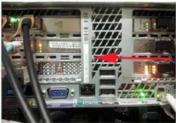
A vertical bar on the rear panel of the appliance compute node contains the serial number.
natural_image
Back view of a computer drive bay showing internal components like CPU socket, drive bays, and network ports (no readable text or symbols)About 5340 Appliance compute node disk dr configurations
The Veritas 5340 Appliance compute node contains five 2 TB SAS hard disk drives. Each disk drive is accessible from the compute node's front panel. An embedded RAID controller on the compute node's mainboard configures four of the five disk drives into two mirrored RAID1 volumes.
The two RAID1 volumes are labeled Volume 0 and Volume 1. The disk drives that are located in slot 0 and slot 1 are configured as the RAID1, VOLUME0 device. These disk drives contain the appliance operating system, the operating system swap file, and the NetBackup application. You can hot-swap one of these disk drives at a time if a drive becomes problematic. However, you cannot operate the appliance if both disk drives are removed.
The disk drives in slot 2 and slot 3 are configured as the RAID1, VOLUME1 device. Volume 1 contains the log files. As with the RAID1, VOLUME0 device, you can hot-swap one disk drive at a time if a drive becomes problematic. However, you cannot operate the appliance if both drives are removed.
The appliance uses the disk drive that is located in slot 4 as a hot-spare disk. If a disk drive in either of the RAID volume experiences a hardware error, the appliance automatically initiates a RAID rebuild operation. During the rebuild operation, the appliance dynamically accesses the hot-spare disk from slot 4 and uses it to rebuild the RAID volume.
Figure 1-1 Veritas 5340 Appliance compute node front panel disk slot assignments

Table 1-2 Veritas 5340 Appliance compute node front panel disk drive configurations
| Slot | RAID level | size (TB) | Disk drive roleDisk drive |
| 2 TBRAID10, 1 | Operating system boot volume / operating system swap file / NetBackup application or Flex applications | ||
| Log files2 TBRAID12, 3 | |||
| Hot spare2 TB4 | |||
| No disk drives installed5 - 11 | |||
Figure 1-2 Veritas 5340 Appliance compute node front panel disk slot assignments

About the 5340 Appliance compute node disk drive LEDs
Each 5340 Appliance compute node disk drive module contains two LEDs on the left side of each module.
Figure 1-3 5340 Appliance compute node disk drive module LEDs

The LED Status descriptions are described in the following table.
Table 1-3 5340 Appliance compute node disk drive LED Status descriptions
| ConditionLED behaviorDescriptionNumk | |||
| 1 | Amber Status LED | OffSolid amberBlinking amber | No disk drive access and no disk drive faultsA disk drive fault has occurredA RAID rebuild is in progress |
| 2 | LED | OffGreen Activity | Power on - the disk drive has spun down |
| Power on - no disk drive activitySolid green | |||
| Blinking green | Power on - the disk drive is processing a commandorPower on - the disk drive is spinning up |
Note: Disk drive modules that do not contain disk drives also have LEDs. Although there may not be disk drive activity, some colored lights may still be seen through the disk modules.
About the 5340 Appliance compute node from panel USB port
The 5340 Appliance compute node front panel includes a USB 2.0-compliant port that supports a data transfer rate of up to 480 Mb/second.

natural_image
Front view of a server rack unit with visible internal components and a labeled 'VERITS' button (no readable text beyond label)About the 5340 Appliance control panel
The 5340 Appliance compute node includes a control panel on the right side of the front panel. System information is shown on this control panel.
Figure 1-4
Control panel

Table 1-4 Control panel system LED descriptions
| System informationLEDLabel | ||
| A | Power button with integrated LED | The Power button toggles the system on and off.See "About the Power button LED states"on page 20. |
| Hard Drive Activity LEDB | The drive activity LED on the front panel indicates drive activity from the on-board hard disk controllers. | |
| C | System ID button with integrated LED | The System ID button toggles the integrated ID LED and the blue server board LED on and off.The system ID LED identifies the system for maintenance when it is racked with similar server systems. |
| Network Activity LEDsD | The front control panel includes four activity LED indicators for each on-board network interface controller (NIC).■ NIC-1 represents network interface controller 1■ NIC-2 represents network interface controller 2■ NIC-3 represents network interface controller 3■ NIC-4 represents network interface controller 4When network links are detected on the controllers, the LEDs are activated and remain on. The LEDs blink when network activity occurs, and the rate at which they blink is determined by the amount of network activity that occurs. | |
| E | NMI button (recessed, tool required for use) | When it is depressed, the NMI button puts the appliance in a halt state, issues a non-maskable interrupt (NMI), and then triggers the non-maskable interrupt. All server data can be lost.Veritas recommends that you do not enable NMI by pressing the NMI button. |
| F | System Cold Reset Button (recessed, tool required for use on non-storage models)System Status LEDG | When depressed, the System Cold Reset button re-boots and re-initializes the appliance.The System Status LED is bi-color indicator that uses the colors green and amber to display the current health of the appliance.Two locations are provided for you to monitor the health of the system. You can find the first location on the front control panel, while the second location is located on the back edge of the server board. It is viewable from the rear of the appliance. Both LEDs show the same state of health.See “About the System Status LED states” on page 17. |
About the System Status LED states
The System Status LED is a bi-color (Green/Amber) indicator that shows the current health of the system. The appliance provides two locations for this feature. The first location is on the Front Control Panel, while the second location is on the back edge of the server board.
Figure 1-5 System Status LED control panel location
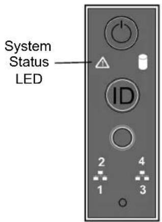
The following table provides a description of each LED state.
Table 1-5 System Status LED states
| DescriptionCriticalityStateColor | |||
| No color | system is not operating | Not readyOff - The System is power off (AC and/or DC)■ System is in EuP Lot6 Off Mode■ System is in S5 Soft-Off State | |
| HealthySolid on (S0)Green that the system is running (in S0 State) and its status is “Healthy”. The system is not exhibiting any errors. AC power is present and BMC has booted and manageability functionality is up and running. | |||
| ~1 Hz blinkGr~1 Hz blinkGr | The system is degradedThe system is operating in a degraded state although still functional.orThe system is operating in a redundant state but with an impending failure warning.Degraded (continued) | System degraded:■ Redundant loss, such as power supply or fan. Applies only if the associated platform sub-system has redundancy capabilities.■ Fan warning or failure when the number of fully operational fans is more than minimum number needed to cool the system.■ Non-critical threshold crossed: Temperature (including HSBP temp), voltage, input power to power supply, output current for main power rail from power supply and Processor Thermal Control (Therm Ctrl) sensors.■ Power supply predictive failure occurred while redundant power supply configuration was present.■ Unable to use all of the installed memory (one or more DIMMs failed/disabled but functional memory remains available).■ Battery failure.■ BMC executing in uBoot. (Indicated by Chassis ID blinking at 3Hz). System in degraded state (no manageability). BMC uBoot is running but has not transferred control to the BMC Linux. Server will be in this state 6-8 seconds after BMC reset while it pulls the Linux image into flash.System degraded (continued):■ BMC booting Linux. (Indicated by Chassis ID solid ON). System in degraded state (no manageability). Control has been passed from BMC uBoot to BMC Linux itself. It will be in this state for 10-20 seconds.■ BMC Watchdog has reset the BMC.■ Power unit sensor offset for configuration error is asserted.■ Hard disk drive HSC is off-line or degraded. | |
| ~1 Hz blinkAm | Non-criticalThe system is operating in a degraded state with an impending failure warning.However, the system is still functioning. | Non-fatal - However, the system is likely to fail:■ Critical threshold crossed – Voltage, temperature (including HSBP temp), input power to power supply, output current for main power rail from power supply and PROCHOT (Therm Ctrl) sensors.■ VRD Hot asserted■ Minimum number of fans to cool the system not present or failed■ Hard drive fault■ Power Unit Redundancy sensor – Insufficient resources offset (indicates not enough power supplies present)■ Correctable memory error threshold has been reached for a failing DIMM when the system is operating in a non-redundant mode. | |
| Solid onAmberSolid onAmber | Critical, non-recoverable – System is haltedCritical, non-recoverable- System is halted | Fatal alarm – system has failed or shutdown:■ CPU CATERR signal asserted■ MSID mismatch detected (CATERR also asserts for this case)■ CPU1 is missing■ CPU Thermal Trip■ No power – power fault■ DIMM failure when there is only one DIMM present; no other good DIMM memory present■ Runtime memory uncorrectable error in non-redundant mode.Uncorrectable Runtime memory error in non-redundant modeDIMM Thermal Trip or equivalentCPU ERR2 signal is assertedBMC/Video memory test failed (Chassis ID shows blue/solid-on for this condition)SBB Thermal Trip or equivalent240VA faultBoth uBoot BMC FW images are bad (Chassis ID shows blue/solid-on for this condition)Fatal Error in processor initialization:Processor family not identicalProcessor model not identicalProcessor core/thread counts not identicalProcessor cache size not identicalUnable to synchronize processor frequencyUnable to synchronize QPI link frequency | |
About the Power button LED states
The Power button is located on the Veritas 5340 Appliance control panel. It is used to turn the appliance on and off.
Figure 1-6 Power button control panel location
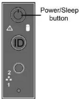
The following table provides a description of each power state.
Table 1-6 Power button LED states
| DescriptionLEDPower ModeState | |||
| OffNon-ACPIPower | The system power is off, and the BIOS has not initialized the chipset. | ||
| OnNon-ACPIPower | The system power is on and the green Power button LED is active. | ||
| S0 | (Advanced Configuration and Power Interface) | Steady onACPI | The system and the operating system are up and running. |
| S5 | (Advanced Configuration and Power Interface) | OffACPI | Mechanical is off and the operating system has not saved any context to the hard disk drive. |
About the appliance compute node rear pane
The rear panel of the appliance compute node has several access ports and other features, which are displayed in the following figures.
Figure 1-7 Veritas 5340 Appliance compute node rear panel overview

Table 1-7 Compute node rear panel features and connectors
| FunctionNumber | |
| 1,2 | Power Supply 1 and Power Supply 2 - Dual, redundant, and hot-swappable power supply modules |
| DB-15 VGA monitor connector3 | |
| Serial port - Serial connection for Veritas Technical Support use only4 | |
| Three stacked USB 3.0 Type A serial ports for general use5 | |
| 6 | IPMI port - An external RJ45 port used for appliance remote management purposes |
| 7 | eth0/NIC 1A 1-GbE port copper connector that is reserved for use during the initial configuration of the appliance. After completing the initial configuration, you can connect NIC1 (eth0) to an administrative network that does not provide any backup data transferFor more information, see the Veritas NetBackupTM 53xx Appliance Initial Configuration Guide - Release 3.1.1.Note: Veritas does not support forming a NIC bond using eth0/NIC1 with other eth/NIC ports. |
| 8 | eth1/NIC 2A 1-GbE port copper connector for general use (NetBackup 5340 Appliance)A 1-GbE port copper connector that you can connect to an administrative network to manage the 5340 Appliance system (Flex 5340 Appliance) |
| 9 | eth2/NIC 3A 1-GbE port copper connector for general use (NetBackup 5340 Appliance)eth2 ports on each of the 5340 compute nodes attach to each other using straight through or cross-over cables. For example, eth2 on first compute node connects to eth2 of the second compute node. (Flex 5340 Appliance) |
| 10 | eth3/NIC 4A 1-GbE port copper connector for general use (NetBackup 5340 Appliance)The eth3 ports on each of the 5340 compute nodes attach to each other using straight through or cross-over cables. For example, eth3 on first compute node connects to eth3 of the second compute node. (Flex 5340 Appliance) |
| PCIe riser assembly 1 *11 | |
| PCIe riser assembly 2 *12 | |
| 13 | PCIe riser assembly 3 *Contains two half height PCIe slots.Note: PCIe riser assembly 2 and riser assembly 3 are riveted together. As a result, riser assembly 2 and riser assembly 3 are removed as one unit. |
* The 5340 Appliance add-in cards are available in multiple configurations. Several configurations include at least one Fibre Channel host bus adapter card for VMware, optimized deduplication over Fibre Channel, or tape library connectivity.
In some configurations the Fibre Channel host bus adapter cards are installed into some of the PCIe slots. If the cards are installed in slots 5 and 6, the configuration supports Fibre Transport Media Server (FTMS) mode. Port 1 of each card is configured by default as Target, while port 2 is configured by default as Initiator. If you want, you can configure port 2 on both cards as Target, and you can configure port 1 on both cards as Initiator.
Note: Only configurations D and E support FTMS.
Note: You cannot bond copper 1 Gb Ethernet ports that are installed in the appliance chassis with PCIe-based 10 Gb Ethernet Fibre Channel ports.
Veritas appliances may include grounding studs in case your lab environment has such a requirement. The studs are located on the rear panel of the appliance. You can use standard grounding practices to connect grounding wires to the studs.
The serial number is located on a vertical bar on the rear panel of the appliance.
Figure 1-8
Serial number location

natural_image
Back view of a server rack with visible ports, connectors, and a red arrow pointing to a specific area (no readable text or symbols)The ports on the rear panel are color-coded for easy identification.
Figure 1-9 5340 Appliance rear port color codes

See "Available 5340 Appliance PCIe-based I/O configurations" on page 24.
Available 5340 Appliance PCIe-based I/O configurations
The rear panel of the Veritas 5340 Appliance contains three PCIe riser card assemblies. PCIe riser card assemblies 1 and 2 each support three standard PCIe cards, while PCIe riser card assembly 3 supports two low profile PCIe cards. The slots are labeled 1 to 8. Slots 1, 2, and 3 are located in PCIe riser card assembly 2. Slots 4, 5, and 6 are located in PCIe riser card assembly 1, while slots 7 and 8 are located in PCIe riser card assembly 3.
Figure 1-10 5340 Appliance rear panel riser assembly locations and PCIe slot number assignments
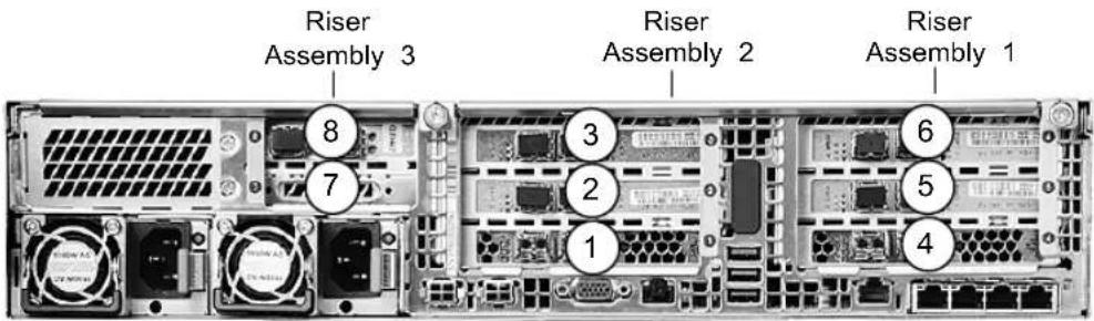
The 5340 Appliance supports multiple PCIe-based I/O configurations. The following table shows the standard I/O configurations that are available with a 5340 Appliance.
Note: A 5340 Appliance high availability (HA) configuration must use two identical 5340 compute nodes with regard to model number and hardware configuration.
For example, you can use two 5340 compute nodes with configuration D. However, you cannot use one 5340 Appliance compute node with configuration D and one 5340 Appliance compute node with configuration B.
This requirement applies to all of the I/O configurations for each model.
Table 1-8 Available 5340 Appliance PCIe-based I/O configurations
| I/O configuration option | Slot 1* | Slot 2 | Slot 3 | Slot 4* | Slot 5 | Slot 6 | Slot 7 | Slot 8 |
| A^† | QLogic QLE269216Gb FC HBA^3 | QLogic QLE844210GbE NIC ^1,3 (iSCSI capable) | QLogic QLE844210GbE NIC ^1,3 (iSCSI capable) | QLogic QLE269216Gb FC HBA^3 | QLogic QLE844210GbE NIC ^1,3 (iSCSI capable) | QLE844210GbE NIC ^1,3 (iSCSI capable) | ReservedQLogicQLE844210GbE NIC ^1,3 (iSCSI capable) | |
| B^†† | QLogic QLE269216Gb FC HBA^3 | QLogic QLE844210GbE NIC ^1,3 (iSCSI capable) | QLogic QLE844210GbE NIC ^1,3 (iSCSI capable) | QLogic QLE269216Gb FC HBA^3 | OLogic QLE844210GbE NIC ^1,3 (iSCSI capable) | QLE25628Gb FC HBA^3 | ReservedQLogicQLE844210GbE NIC ^1,3 (iSCSI capable) | |
| C^†† | QLogic QLE269216Gb FC HBA^3 | QLogic QLE844210GbE NIC ^1,3 (iSCSI capable) | QLogic QLE844210GbE NIC ^1,3 (iSCSI capable) | QLogic QLE269216Gb FC HBA^ 3 | QLogic QLE25628Gb FC HBA^3 | QLE25628Gb FC HBA^3 | ReservedQLogicQLE844210GbE NIC ^1,3 (iSCSI capable) | |
| D^†† | QLogic QLE269216Gb FC HBA^3 | QLogic QLE25628Gb FC HBA^3 | QLogic QLE844210GbE NIC ^1,3 (iSCSI capable) | QLogic QLE269216Gb FC HBA^3 | QLogic QLE25628Gb FC HBA^3 | QLE25628Gb FC HBA^3 | ReservedQLogicQLE844210GbE NIC ^1,3 (iSCSI capable) | |
| E^†† | QLogic QLE2692 16Gb FC HBA^3 | QLogic QLE2562 8Gb FC HBA^3 | QLogic QLE2562 8Gb FC HBA^3 | QLogic QLE2692 16Gb FC HBA^3 | QLogic QLE2562 8Gb FC HBA^3 | QLE2562 8Gb FC HBA^3 | Reserved | QLogic QLE8442 10GbE NIC 1,3 (iSCSI capable) |
* The 16Gb Fibre Channel HBA ports in slots 1 and 4 are used to connect the NetBackup 5340 Appliance compute node to the Veritas 5U84 Primary Storage Shelf.
^ Available with both NetBackup Appliance software release 3.0 or later, and the Flex Appliance software release
^†† Available only with NetBackup Appliance software release 3.0 or later
PCIe card cable connection types:
^1 Direct-Attach copper cable (also called a Twinaxial cable or Twinax)
^2 Standard copper
^3 Fiber optic cable
Figure 1-11 5340 Appliance rear panel riser assembly locations
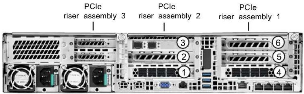
See "Total 5340 Appliance on-board and PCIe-based I/O ports" on page 26.
Total 5340 Appliance on-board and PCIe-based I/O ports
The following table shows the total number of I/O ports that are available with each 5340 Appliance I/O configuration.
Table 1-9 Total number of5340 Appliance on-board and PCIe-based I/O ports for each available I/O configuration
| I/O Configuration option | 16Gb Fibre Channel PCIe ports (optical) | 10Gb Ethernet/iSCSI PCIe ports (copper) | 8Gb Fibre Channel PCIe ports (optical) | 1Gb Ethernet ports (copper) |
| 0104A | 4(on-board) | |||
| B | 4 | 8 | 2 | 4(on-board) |
| C | 4 | 6 | 4 | 4(on-board) |
| D | 4 | 4 | 6 | 4(on-board) |
| E | 4 | 2 | 8 | 4(on-board) |
Cable connection types:
copper = Standard copper cable or Direct-Attach copper cable
Note: Direct-Attach copper cable is also known as a Twinaxial cable or Twinax
optical = fiber optic cable
QLE2692 dual-port 16Gb Fibre Channel host bus adap
The QLE2592 dual-port 16Gb Fibre Channel (FC) host bus adapter connects the appliance compute node to the 5U84 Primary Storage Shelf.

natural_image
Green PCI expansion card with dual ports and a heat sink, no visible text or symbolsTable 1-10 QLE2692 dual-port 16Gb Fibre Channel host bus adapter specifications
| DescriptionItem | |||||
| height | Full HeightBracket | ||||
| Low-profile PCIe card (6.6 inches × 2.731 inches)Form factor | |||||
| consumption (watts) | 9.3 WPower | ||||
| temperature | 0°C to 55°C (32°F to 131°F)Operating | ||||
| temperature | -20°C to 70°C (-4°F to 158°F)Storage | ||||
| humidity | 10% to 90%Operating | ||||
| humidity | 5% to 95%Storage | ||||
| interface type | PCIe v3.0System | ||||
| UL, CSA, TUV, CB, FCC, VCCICertifications | |||||
| cable distances | RateMaximum Cable and Distance (m)(multimode optic cable) | ||||
| OM4OM3OM2OM1 | |||||
| 400380150704Gbps | |||||
| 19015050218Gbps | |||||
| 12510035*16Gbps | |||||
* Not supported
The following table describes the Fibre Channel host bus adapter LED indicator status activity.
Table 1-11 QLE2592 dual-port 16Gb Fibre Channel host bus adapter LED indicator status activity
| Yellow LED | Green LED | Amber LED | Activity |
| Off | Off | Off | Power off |
| On | On | On | Power on (pre-firmware initialization) |
| Blink | Blink | Blink | Power on (post-firmware initialization ) |
| Blink alternately | Blink alternately | Blink alternately | Firmware error |
| Off | Off | On/Blink | 4Gbps link / input-output (I/O) activity |
| Off | On/Blink | Off | 8Gbps link / input-output (I/O) activity |
| On/Blink | Off | Off | 16Gbps link / input-output (I/O) activity |
QLE8442 dual-port 10Gb Ethernet/iSCSI capable card wi SFP+ modules
The QLE8442 is a dual-port 10GbE network interface card. It supports simultaneous LAN (TCP/IP) and SAN (Fibre Channel over Ethernet [FCoE] and iSCSI) traffic at 10Gbps Ethernet (GbE) line rate speeds. The card also provides very low host CPU usage by enabling full hardware offloads.
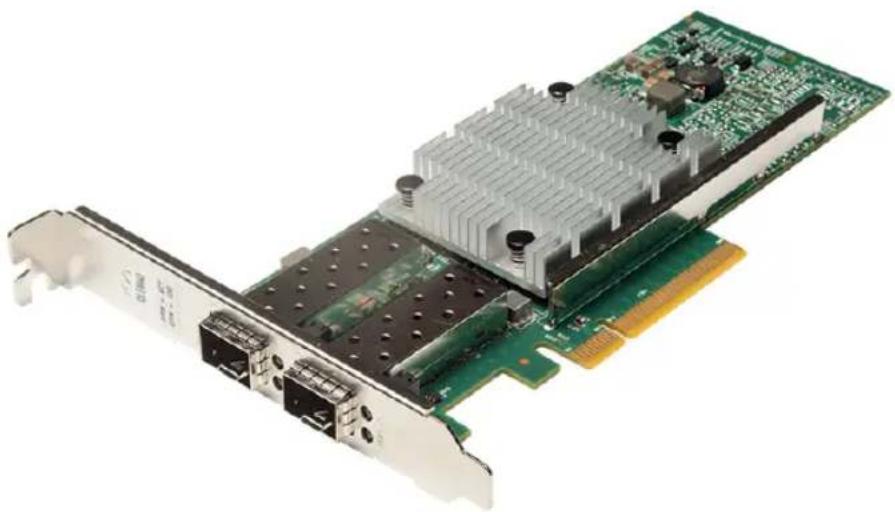
natural_image
Close-up of a green PCI network card with dual ports and a heat sink (no visible text or symbols)Table 1-12 QLE8442 dual-port 10Gb Ethernet card specifications
| SpecificationItem | |
| Full heightBracket height | |
| 9.65 watts (nominal)Power consumption | |
| type | PCIe v3.0System interface |
| 8.0 GT/s, 8-laneSpeed and slot width | |
| Ethernet | iSCSISTorage over |
| LED indicators | LINK/ACTIVITYOff = No link (cable disconnected)Continuously illuminated = Line onBlinking = Network activityFCC A, ICES A, UL, CE, VCCI, CISPR, KCCCertifications |
| temperature | 0 to 55 C (32 TO 131 f)Operating |
| -40 to 65 C (-40 to 149 F)Storage temperature | |
| 7% to 93% @ 55 COperational humidity | |
| 93% maximum at 65 CStorage humidity | |
| 100 LFM @ 55 CAir flow |
To purchase a QLE8442 dual-port 10Gb Ethernet card with SFP+ modules for your appliance, contact your Veritas sales representative, or your Veritas Partner representative.
QLE8442 dual-port 10Gb Ethernet card with SFP+ modules
DescriptionSKU Number
18293 XX40 QLOGIC QLE8442 10GBPS DUAL PORT ETHERNET/ISCSI CRU with SFP modules included
QLE2562 dual-port 8Gb Fibre Channel host bus adapted with SFP+ modules
The QLE2562 dual-port 8Gb Fibre Channel (FC) host bus adapter with SFP+ modules connects the appliance to clients or other devices for fiber transport data transfer.

natural_image
Close-up of a green PCI EDS card with multiple Ethernet ports and a central processor (no visible text or symbols)Table 1-13 QLE2562 dual-port 8Gb Fibre Channel host bus adapter port specifications
| DescriptionItem | ||||
| Full HeightBracket height | ||||
| consumption (watts) | 6.2 watts (typical)Power | |||
| temperature | 0°C to 55°C (32°F to 131°F)Operating | |||
| temperature | -40°C to 70°C (-40°F to 158°F)Storage | |||
| Operating humidity | 5% RH to 93% RH (non-operating, non-condensing) and 5% RH to 93% RH (operating, non-condensing) | |||
| interface type | PCIe v3.0System | |||
| FCC B, UL, CE, VCCI, CISPR, KN, CNSCertifications | ||||
| connections | OM3OM2OM1RateExternal | |||
| 500m300m150m2Gbps | ||||
| 380m150m70m4Gbps | ||||
| 21m8Gbps | 150m50m | |||
The following table describes the Fibre Channel host bus adapter LED indicator status activity.
Table 1-14 QLE2562 dual-port 8 Gb Fibre Channel host bus adapter LED indicator status activity
| LED | ActivityAmber LEDGreen LEDYellow | ||
| Power offOffOffOff | |||
| Power on (pre-firmware initialization)OnOnOn | |||
| Power on (post-firmware initialization )BlinkBlinkBlink | |||
| Blink alternately | alternately | Firmware errorBlink alternatelyBlink | |
| 4Gbps link / input-output Off(Off) activityOn/Blink | |||
| 8Gbps link / input-output (I/O) activityOffOn/Blink | |||
| OffOffOn/Blink | k16Gbps link / input-output (I/O) activity |
To purchase a QLE2562 dual-port 8Gb Fibre Channel host bus adapter for your appliance, contact your Veritas sales representative, or your Veritas Partner representative.
5340 Appliance on-board network interface port locations and speeds
Four 1Gb Ethernet on-board network interface ports are available for general use with each 5340 Appliance.
Figure 1-12 Appliance compute node on-board network interface port locations

Table 1-15 Appliance compute node on-board network interface port information
| FunctionPort | |
| eth0/NIC1(copper/RJ45 connector) | Used for the initial configuration of the appliance. After completing the initial configuration, you can connect NIC1 (eth0) to an administrative network that does not provide any backup data transfer.Used for a direct laptop connection using the default IP address of 192.168.229.233. The connected laptop can be used for initial configuration purposes, along with other appliance administrative functions. After removing the connected laptop, you can you can connect NIC1 (eth0) to an administrative network that does not provide any backup data transfer.For more information, see the Veritas NetBackupTM 53xx Appliance Initial Configuration Guide - Release 3.1.Note: Veritas does not support forming a NIC bond using eth0/NIC1 with other eth/NIC ports. |
| eth1/NIC2(copper/RJ45 connector) | A 1-GbE port for general use (NetBackup 5340 Appliance only)A 1-GbE port that can be configured as an administrative network port that does not provide any backup data transfer (Flex 5340 Appliance only)A 1-GbE port that can be configured as an administrative network port that does not provide any backup data transfer. |
| eth2/NIC3(copper/RJ45 connector) | A 1-GbE port for general use (NetBackup 5340 Appliance only)A 1-GbE private network port that is used for connections between the two appliance compute nodes (Flex 5340 Appliance only) |
| eth3/NIC4(copper/RJ45 connector) | A 1-GbE port for general use (NetBackup 5340 Appliance only)A 1-GbE private network port that is used for connections between the two Appliance compute nodes (Flex 5340 Appliance only) |
| IPMI port(copper/RJ45 connector) | A 1-GbE port that is used for appliance remote management purposes. |
| * | A 10-GbE port that is used for general network uses.eth4/pubeth0/NIC |
| * | A 10-GbE port that is used for general network uses.eth5/pubeth1/NIC |
Table 1-15 Appliance compute node on-board network interface port information (continued)
| FunctionPort |
* Virtual IP addresses are assigned to the eth4 and eth5 ports of both appliance compute nodes.
About the Veritas 5U84 Storage Shelves
This chapter includes the following topics:
■ About Veritas 5340 Appliance storage shelves
■ About the 5U84 Primary Storage Shelf and 5U84 Expansion Storage Shelf rear components
About Veritas 5340 Appliance storage shelves
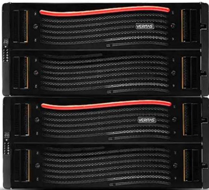
natural_image
Three black server racks with red VERTAS heat sinks, no visible text or symbols on the racks themselves.Veritas offers two external storage shelf models for the Veritas 5340 Appliance.
These include the:
■ Veritas 5U84 Primary Storage Shelf (required)
■ Veritas 5U84 Expansion Storage Shelf (optional)
Both of the 5U84 Storage Shelf chassis include a set of common internal core components, along with a set of plug-in modules.
The core components include:
■ Two sliding disk drawers that contain Disk Drive In Carrier (DDIC) modules
■ A front operations panel
■ A front bezel
- Mid-plane printed circuit boards (PCB) that interface with controllers on the 5U84 Primary Storage Shelf and the 5U84 Expansion Storage Shelf.
In addition to the core components, the storage shelves also incorporate the following plug-in modules:
■ Two 16Gb Fibre Channel RAID controller modules (5U84 Primary Storage Shel only)
■ Two Storage Bay Bridge 2.1-compliant Expansion I/O controller modules (5U84 Expansion Storage Shelf only)
■ Two power supply units (PSUs)
■ Five fan modules
■ Up to 84 Disk Drive In Carrier (DDIC) modules with drives installed
■ A rail kit for rack mounting
The 5U84 Primary Storage Shelf and the 5U84 Expansion Storage Shelf each use a 5U chassis. Each chassis contains two sliding disk drive drawers that are located in the front of the storage shelf. Each drawer holds 42 Disk Drive In Carrier (DDIC) modules. The DDIC modules are installed in the drive drawer slots, which hold a total of 84 disk drives. Each DDIC module holds SAS3, 7200 rpm hard disk drives, in either 4TB or 8TB capacities. The disk drives and the DDIC modules are hot-swappable and can be replaced on-site while the storage shelf is operational.
Note: Whether you use 4TB or 8TB disk drives in the storage shelves, each storage shelf drawer must be populated with disk drives of the same capacities.
In each storage shelf, two disk drives are used as global hot spares. Four of the disk drives provide storage space for a dedicated RAID 10 metadata volume group. When 4TB disk drives are used, the storage shelf provides 7.27TBs of metadata storage capacity. When 8TB disk drives are used, the storage shelf provides 15.75TBs of metadata storage capacity. The remaining disks are configured in a storage group that uses RAID 6 disk array technology. These disks are used for MSDP and AdvancedDisk data storage purposes. Depending on the storage configuration you purchase, the NetBackup 5340 Appliance storage system supports up to 1,920TBs of usable data storage space.
Note: RAID10 is also known as RAID 1+0. It combines disk mirroring and disk striping to protect data.
Available appliance storage options
The Veritas 5340 Appliance compute nodes do not contain internal disk space on which to store data. Instead, the 5340 Appliance uses the required Veritas 5U84 Primary Storage Shelf as the main data storage device. The 5U84 Primary Storage Shelf connects to the 5340 Appliance compute nodes and uses RAID 6 drive sets to protect the stored data.
Note: RAID 6 is also known as double-parity RAID. It uses two parity stripes on each disk to protect data. RAID 6 allows for two hard disk failures within the RAID disk array before any data is lost.
If additional data storage space is required, you can connect up to three Veritas 5U84 Expansion Storage Shelves to the existing 5U84 Primary Storage Shelf. The 5U84 Expansion Storage Shelves connect to the 5U84 Primary Storage Shelf using SAS3 data cables. After connecting the shelves, the disk drives in the 5U84 Expansion Storage Shelf use RAID 6 sets that are controlled by the 5U84 Primary Storage Shelf to protect the stored data.
Table 2-1 shows the available storage shelf storage capacities for the 5340 Appliance running NetBackup software using 4-TB and 8-TB disk capacities.
Note: Veritas does not support mixing 4TB and 8TB disk drives within a storage shelf.
Table 2-1 Usable NetBackup 5340 Appliance 5U84 Storage Shelf storage capacities by disk drive capacities
| Usable storage capacities (using 8-TB Drives) | Usable storage capacities (using 8-TB Drives) | |
| 240TB120TB | ||
| 480TB240TB | ||
| 720TB360TB | ||
| 480TB | 960TB* | |
| 600TB | 1200TB* | |
| 720TB | 1440TB* | |
| 840TB | 1680TB* | |
| 960TB* | 1920TB* |
*NetBackup 5340 Appliance software version 3.1 supports up to 916TBs of usable MSDP storage capacity.
Figure 2-1 Available NetBackup 5340 Appliance 5U84 Storage Shelf configurations

bar_stacked
| Total Capacity | With 4TB | Shelves | With 8TB | Shelves | | -------------- | -------- | ------- | -------- | ------- | | 120 TB | | | | | | 240 TB | | | | | | 360 TB | | | | | | 480 TB | | | | | | 600 TB | | | | | | 720 TB | | | | | | 840 TB | | | | | | 960 TB | | | | | | 1200 TB | | | | | | 1440 TB | | | | | | 1680 TB | | | | | | 1920 TB | | | | | Legend: Half populated 5U84 Storage Shelf - 45 disk drives; Fully populated 5U84 Storage Shelf - 84 disk drives; 4TB 5U84 Storage Shelf; 8TB 5U84 Storage Shelf; ½ 4TB 5U84 Storage Shelf = 120 TB; Full 4TB 5U84 Storage Shelf = 240 TB; ½ 8TB 5U84 Storage Shelf = 240TB; Full 8TB 5U84 Storage Shelf = 480TBTable 2-2 shows the available storage shelf storage capacities for the 5340 Appliance running Flex software using 4-TB and 8-TB disk capacities.
Table 2-2 Usable Flex 5340 Appliance 5U84 Storage Shelf storage capacities by disk drive capacities
| Usable storage capacities (using 4-TB) | Disable storage capacities (using 8-TB Drives) |
| 480TB240TB | |
| 960TB480TB | |
| 1440TB720TB | |
| 1920TB960TB |
* Flex 3340 Appliance software supports up to 916TBs of usable MSDP storage capacity when using one MSDP storage pool. When multiple MSDP storage pools are used, you can use the entire amount of usable storage capacit for MSDP storage if desired. The total amount of usable storage capacity depends on the number of storage shelves that are connected to the Flex compute node.
Figure 2-2 Available Flex 5340 Appliance 5U84 Storage Shelf configurations

bar
| Total Capacity With 4TB | shelves With 8TB | shelves With 1920 TBI | |---|---|---| | 240 | | | | 480 | | | | 720 | | | | 960 | | | | 1440 | | | | 1920 | | | | Storage | Shelf Population | Storage Type | | :--- | :--- | :--- | | Fully populated 5U84 | Storage Shelf - 84 disk drives | Fully populated 5U84 | | Fully populated 5U84 | Storage Shelf - 84 disk drives | Fully populated 5U84 | | Full 8TB | Storage Shelf = 480TB | Full 8TB | | Full 4TB | Storage Shelf = 240 TB | Full 4TB | The chart displays a horizontal bar chart with three bars representing different storage configurations. The values are labeled on each bar.To determine the hardware configuration for the storage capacities that environment requires, contact your Veritas sales representative, or your Veritas Partner representative.
About the Veritas 5U84 Storage Shelf disk drive drawers
This section discusses the 5U84 Primary Storage Shelf and 5U84 Expansion Storage Shelf disk drive drawers and the components that comprise the drawers.
Disk drive drawers
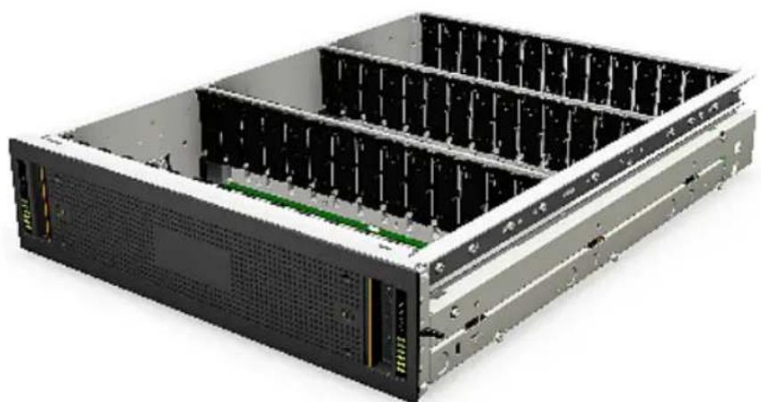
Figure 2-3 5U84 Primary Storage Shelf/5U84 Expansion Storage Shelf disk drive drawer
natural_image
3D rendering of a server rack with multiple drive bays and ventilation slots (no visible text or labels)The 5U84 Primary Storage Shelf and the 5U84 Expansion Storage Shelf each use a 5U chassis. Each chassis contains two sliding drawers that are accessible from the front of the storage shelves. Each drawer holds 42 Disk Drive In Carrier (DDIC) modules. The DDIC modules are installed in each of the drive drawer slots, which can hold a total of 84 disk drives. Each DDIC module holds one 3.5" SAS3, 7200 rpm hard disk drive, in either 4-TB or 8-TB capacities. The disk drives and the DDI modules are hot-swappable and can be replaced on-site while the storage shelf is operational.
Disk drive slot numbering
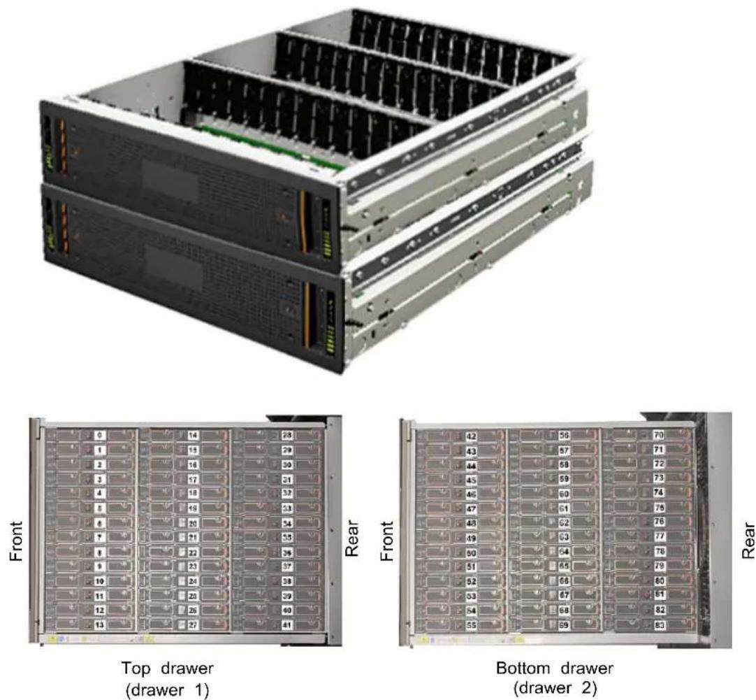
Each disk drive drawer in a 5U84 storage shelf is divided into three compartments. The compartments contain the individual drive slots that hold the DDIC modules and the disk drives.
In the top drive drawer, the drive slots are numbered from left to right, beginning with the first compartment that is closest to the front panel. The drive slots in this compartment are numbered 0 to 13. The drive slots in the second compartment are in the middle of the drive drawer. These slots are numbered 14 to 27. The drive slots in third compartment are closest to the rear of the shelf. These slots are numbered 28 to 41.
In the bottom drive drawer, the drive slots are numbered from left to right, beginning with the first compartment that is closest to the front panel. The drive slots in this compartment are numbered 42 to 55. The drive slots in the second compartment are in the middle of the drive drawer. These slots are numbered 56 to 69. The drive slots in third compartment are closest to the rear of the shelf. These slots are numbered 70 to 83.
See Figure 2-4 on page 43.
Figure 2-4 Disk drive slot numbering
Disk Drive In Carrier (DDIC) modules
All storage shelf hard disk drives are housed in DDIC modules. Each disk drive drawer accepts a Disk Drive In Carrier (DDIC) module for each disk drive slot in the drawer. DDIC modules enable disk drives to be quickly inserted and removed without turning off the 5U84 storage shelves. In addition, each DDIC prevents mis-alignment and damage to the disk drive connectors during the disk drive insertion and removal process.
For troubleshooting purposes, DDIC modules provide one amber drive fault LED indicator per disk drive. The fault indicator enables you to easily identify a failed drive carrier in the drive drawer. You can see drive fault LED indicator when the disk drive drawer is open.
Figure 2-5 Disk Drive In Carrier (DDIC) module

natural_image
3D rendering of an electric battery pack with green internal structure and orange top tabs (no text or symbols visible)Figure 2-6 Disk Drive In Carrier (DDIC) module components and locations

Table 2-3 5U84 Storage Shelf DDIC component locations
| ComponentNumber | |
| 1 | Touch pointsNote: Touch points are used to facilitate the removal of the DDIC module from the storage shelf drawer. |
| Latch button2 | |
| Drive Fault LED3 | |
| Disk drive capacity label4 | |
| Dongle5 |
Disk Drive Drawer printed circuit board (PCB) assemb
Each disk drive drawer in a 5U84 storage shelf uses a printed circuit board (PCB) assembly to provide the electrical connectivity to the drawer's disk drives.
Along with providing the electrical connectivity to the disk drives, PCB assemblies also provide:
■ Mounting platforms for the drawer cabling system
■ Redundant power paths to each disk drive
■ Redundant 12Gb/s SAS signal paths to each disk drive
■ Provide technical feedback to the system when a drawer is opened or closed. PCB assemblies include the following components:
■ Three drawer Baseplane cards
■ One right side Drawer Sideplane card
■ One left side Drawer Sideplane card
Figure 2-7 Disk Drive Drawer PCB assembly

Table 2-4 Disk drive drawer PCB assembly components
| ItemLabel | |
| Drawer Sideplane card (left)A | |
| Drawer Sideplane card (right)B | |
| Baseplane cardC |
Each PCB assembly contains two Drawer Sideplane cards. One Sideplane card mounts on the right side of the disk drawer, while the other card mounts on the left side of the drawer.
Drawer Sideplane cards provide power paths to the drawer Baseplanes and the DDICs and their installed disk drives. Sideplane cards also provide 12Gb/s SAS connections.
Sideplane cards are hot swappable and replaceable by service personnel while the storage shelf is running in a rack.
Note: Removing the Sideplane upper metal cover removes power to the Sideplane, which enables the faulty Sideplane to be hot-swapped.
Figure 2-8 Inside and outside views of a right side Sideplane card

natural_image
Two 3D isometric views of a green printed circuit board with visible components and connectors (no text or symbols)Three Drawer Baseplanes comprise each PCB assembly. Drawer Baseplanes provide a dual path for 12Gb/s SAS connectivity between the Drawer Sideplane cards and the DDICs. They also provide power to the DDICs from either the right or the left Drawer Sideplane cards.
The Drawer Baseplanes also provide four remote temperature sensing diodes that monitor disk drive temperatures within the disk drive drawers.
Figure 2-9 Drawer Baseplane example

natural_image
3D rendering of a green circuit board with orange connectors and gray components (no text or symbols)Drawer Sideplane Status panels
Drawer Sideplane Status panels are located on the front of the 5U84 storage shelves. These panels provide status and the activity information about the Sideplane card.
Figure 2-10 Drawer Sideplane Status panel locations
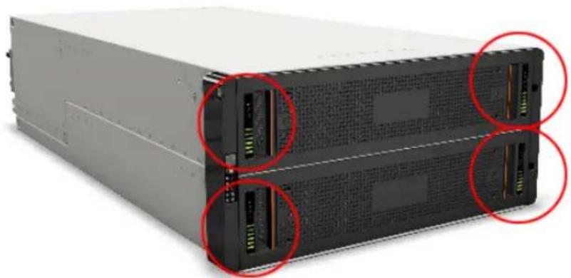
natural_image
Front view of a server rack with multiple drive bays and red-circled highlights (no visible text or labels)Figure 2-11 5U84 Primary Storage Shelf / 5U84 Expansion Storage Shelf
Drawer Sideplane Status panel

Table 2-5 Drawer Sideplane Status panel descriptions
| ItemNumber | |
| Sideplane card OK / Power good1 | |
| Sideplane card Fault2 | |
| Logical Fault3 | |
| Cable Fault4 | |
| Activity Bar Graph5 |
The following table describes the Drawer Sideplane LED statuses.
Table 2-6 Drawer Sideplane LED statuses
| Status | Power(Green) | Drawer Fault(Amber) | Cable Fault(Amber) | Logical Fault(Amber) | Activity Bar Graph(Green) |
| card OK / Power Good | XOffOffOffOnDrawer Side | ||||
| card Fault | OffXXOnOffDrawer Sidep | ||||
| occurred causing loss of availability or redundancy | XXXOnOnDrive failure | ||||
| state (SES)Indicated | XFlashingXXOnArray in | ||||
| OffXOnXOffCable Fault | |||||
| Drive Activity | OffOffOn | Off | On* |
X = Disregard
* The Activity Bar Graph is a six-segment indicator that shows activity of the SAS disk drive interface to the Sideplane. If none of the segments are lit, then there is no SAS disk drive activity occurring. Increasing disk drive activity is measured upward, starting with the bottom segment to the top segment. When full disk drive activity occurs, all six segments are lit.
Drawer Sideplane hot swap LED indicators
Drawer Sideplane hot-swap LED indicator lights are mounted on each drawer's Sideplane printed circuit board assembly. They are visible through each Sideplane's metal frame when the drawer is open.
Figure 2-12
Drawer Sideplane hot-swap LED location

Surrounding metal frame
The following table describes the Drawer hot-swap Sideplane LED indicator statuses.
Table 2-7 Drawer Sideplane Hot-swap LED indicator statuses
| Power disabled LED (Amber)12V | ||
| power present(DO NOT hot-swap the sideplane) | XOnSideplane 12V | |
| disabled(OK to hot-swap the Sideplane) | OnOffSideplane 12V is | |
| X = Disregard | ||
5U84 Primary Storage Shelf and the 5U84 Expansion Storage Shelf control panel
The control panel is installed on the left side of both the 5U84 Primary Storage Shelf and the 5U84 Expansion Storage Shelf. It is functionally the same for both systems.
Figure 2-13 Control panel location
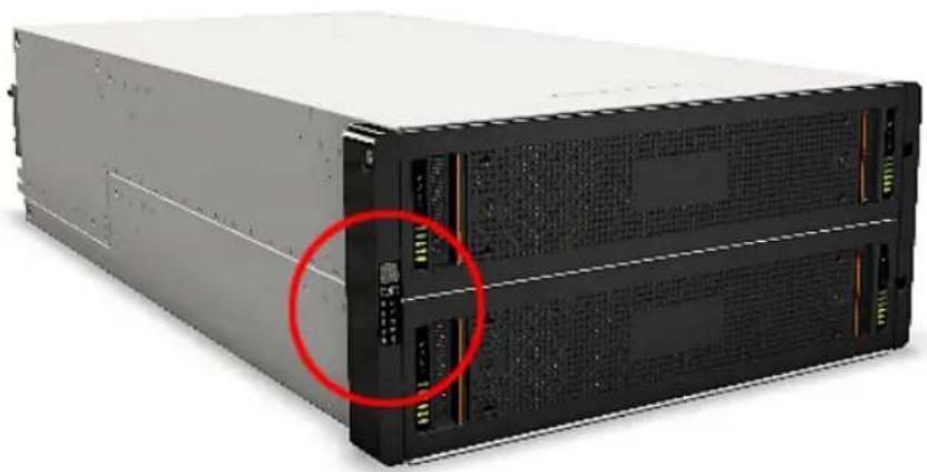
natural_image
Front view of a server rack unit with two drive bays and a red circle highlighting a component (no visible text or labels)Figure 2-14 Control panel

The following table describes the control panel functions.
Table 2-8 Control panel functions and descriptions
| DescriptionFunctionNumber | ||
| 1 | Unit Identification Display | The Unit Identification Display is a dual digit display that provides information about the storage shelf. Its primary function is to assist in the configuration of multiple storage shelves that are connected to the appliance. |
| Input button2 | The Input button enables you to set the Unit Identification display number. | |
| 3 | Power On / Standby LED (Green or Amber) | The Power On/Standby LED shows Amber when only standby power is available. Otherwise, the LED shows Green when system power is available. |
| 4 | Module Fault LED (Power Cooling Module, I/O module status) (Amber) | The Module Fault LED illuminates when there is a system hardware fault. The system hardware fault may be associated with a fault LED on a Power Cooling Module (PCM) or on an I/O module. |
| 5 | Logical Fault LED (Amber) | The Logical Status LED shows a change of status or a fault. Typically these changes of status or faults are associated with the shelf's disk drives. However, the Logical Status LED can also indicate an issue with an internal RAID controller or external RAID controller, or with a host bus adapter. |
| 6 | Top Drawer Fault (Amber) | The Top Drawer Fault LED (drawer 1) shows a change of status or a fault with the top disk drive drawer in the storage shelf. |
| 7 | Bottom Drawer Fault (Amber) | The Bottom Drawer Fault LED (drawer 2) shows a change of status or a fault with the bottom disk drive drawer in the storage shelf. |
About the 5U84 Primary Storage Shelf and Expansion Storage Shelf rear components
This section describes the rear components of the 5U84 Primary Storage Shelf and 5U84 Expansion Storage Shelf.
The 5U84 Primary Storage Shelf and the 5U84 Expansion Storage Shelf contain the following removable rear components:
■ Fibre Channel RAID Controllers (5U84 Primary Storage Shelf only)
■ Expansion I/O modules (5U84 Expansion Storage Shelf only)
■ Fan modules
■ Power Supply Units (PSUs)
Figure 2-15 5U84 Primary Storage Shelf rear components

Table 2-9 5U84 Primary Storage Shelf rear component locations
| ItemLetter | |
| A | RAID Controllers(from left to right) RAID Controller A, RAID Controller B |
| B | Fan modules(from left to right) Fan Module 0, Fan Module 1, Fan Module 2, Fan Module 3, and Fan Module 4 |
| C | Power Supply Units(from left to right) PSU 0, PSU 1 |
Figure 2-16 5U84 Expansion Storage Shelf rear components

Table 2-10 5U84 Expansion Storage Shelf rear component locations
| ItemLetter | |
| A | Expansion I/O modules(from left to right) Expansion I/O Module A, Expansion I/O Module B |
| B | Fan modules(from left to right) Fan Module 0, Fan Module 1, Fan Module 2, Fan Module 3, and Fan Module 4 |
| C | Power Supply Units(from left to right) PSU 0, PSU 1 |
5U84 Primary Storage Shelf
The 5U84 Primary Storage Shelf uses two Fibre Channel RAID controllers, which are located in the top two slots of the back panel. The RAID controllers provide RAID data protection technology for the data that is stored on the 5U84 Primary Storage Shelf disk drives. The RAID controllers also provide RAID data protection technology for the optional 5U84 Expansion Storage Shelves that you connect to the 5U84 Primary Storage Shelf.
Fiber optic cables connect the 5340 Appliance compute nodes to the 5U84 Primary Storage Shelf through the storage shelf's RAID controllers.
Five high performance fan modules connect to the storage shelf's midplane connector through the middle slots. Each fan module contains two contra-rotating high performance fans, along with separate power and control circuits for each internal fan.
Two redundant Power Supply Units (PSUs) are located in slots beneath the fan modules.
To operate, the 5U84 Primary Storage Shelf must have at least one functioning RAID Controller, one functioning power supply unit, and four functioning fan modules.
5U84 Expansion Storage Shelf
The 5U84 Expansion Storage Shelf uses two Expansion I/O modules, which are located in the top two slots of the back panel. The Expansion I/O modules provide SAS3 I/O data transfers between the 5U84 Primary Storage Shelf and the 5U84 Expansion Storage Shelf. The Expansion I/O modules also provide I/O data transfers between the first 5U84 Expansion Storage Shelf and up to two additional 5U84 Expansion Storage Shelves.
SAS3 cables connect the 5U84 Expansion Storage Shelf to the 5U84 Primary Storage Shelf through the 5U84 Expansion Storage Shelf's Expansion I/O modules. SAS3 cables are also used to daisy chain up to two additional 5U84 Expansion Storage Shelves to the first 5U84 Expansion Storage Shelf.
Five high performance fan modules connect to the storage shelf's midplane connector through the middle slots. Each fan module contains two contra-rotating, high performance fans, along with separate power and control circuits for each internal fan. The device must have at least one functioning RAID Controller, one functioning power supply module, and one functioning fan module.
Two redundant Power Supply Units (PSUs) are located in slots beneath the fan modules.
To operate, the 5U84 Expansion Storage Shelf must have at least one functioning Expansion I/O module, one functioning PSU, and four functioning fan modules.
See "Veritas 5U84 Expansion Storage Shelf Expansion I/O modules" on page 60.
Veritas 5U84 Primary Storage Shelf RAID Controllers
The Veritas 5U84 Primary Storage Shelf uses dual, hot swappable Fibre Channel RAID controllers. These controllers create and manage the 5U84 Primary Storage Shelf disk drive RAID sets that contain backed up data. They also create and manage the RAID sets on 5U84 Expansion Storage Shelves when those are attached to the 5U84 Primary Storage Shelf.
The Fibre Channel RAID controllers run RAID levels 6 and 10 on the storage shelf. RAID 10 is also referred to as RAID 1+0. RAID 6 offers the highest level of data
protection. It allows simultaneous write operations, while also allocating two sets of parity data across the drives that comprise the RAID 6 array.
RAID 10 uses mirroring and striping technology without the use of parity. It enables the creation of large high performance disk groups for data storage purposes, while also providing the fault tolerance protection that mirroring offers. RAID 10 is used to protect the metadata that is stored on the storage shelves.
The Fibre Channel RAID controllers also provide one SAS3 port. The SAS3 port enables data to flow at SAS3 data transfer rates between the 5U84 Primary Storage Shelf and the first optional 5U84 Expansion Storage Shelf.
Figure 2-17 Veritas 5U84 Primary Storage Shelf Fibre Channel RAID controller

The following figure and table provides component details for the Veritas 5U84 Primary Storage Shelf Fibre Channel RAID controller modules.
Figure 2-18 Veritas 5U84 Primary Storage Shelf Fibre Channel RAID Controller components and locations

The following figure and table provides component details for the Veritas 5U84 Primary Storage Shelf Fibre Channel RAID controller modules.
Table 2-11 Veritas 5U84 Primary Storage Shelf Fibre Channel RAID controller components
| ComponentNumber | |
| SAS3 port1 | |
| Ethernet port2 | |
| USB port3 | |
| Serial ports (Service only)4 | |
| Indicator LEDs5 | |
| 16Gb Fibre Channel ports6 | |
| Activity LED7 | |
| Activity LEDs8 |
The following figure and table provides RAID controller indicator LED details for the Veritas 5U84 Primary Storage Shelf Fibre Channel RAID controller modules.
Figure 2-19 Veritas 5U84 Primary Storage Shelf Fibre Channel RAID Controller indicator LED details

1
Table 2-12 Veritas 5U84 Primary Storage Shelf Fibre Channel RAID Controller indicator LED descriptions and definitions
| DefinitionDescriptionLED | ||
| 1 | Host 4/8/16Gb Fibre Channel ^1 Link Status / Link Activity | Off - No link detected.Green- The port is connected and the link is up.Blinking green - The link has I/O activity. |
| 2 | Host 10GbE iSCS ^2,3 Link Status / Link Activity | Off - No link detected.Green- The port is connected and the link is up.Blinking green - The link has I/O activity or replication activity. |
| 3 | OK | Off - A controller issue has been detected, or the controller is turned off.Blinking green - The system is starting.Green - The controller is operating normally. |
| Fault4 | Off - The controller is operating normally.Amber - A controller fault has been detected or a service action is required.Blinking amber - Hardware-controller power on error, or a cache flush or restore error. | |
| OK to Remove5 | Off - The controller is not prepared for removal.Blue - The controller is prepared for removal. | |
| White - The controller is being identified.Identify6 | ||
| 7 | Cache Status ^4 | Off - In a working controller, the cache is clean (contains no unwritten data). This is an occasional condition that occurs while the system is booting.Green - The cache is dirty (contains unwritten data) and the operation is normal. The unwritten information can be the log data or the debug data that remains in the cache. By itself, a Green cache status LED does not indicate that any user data is at risk or that any action is necessary.Blinking Green - A Compact Flash flush or a cache self-refresh is in progress, indicating cache activity. |
| 8 | Network Port Link Activity Status ^5 | Off - The Ethernet link is not established, or the link is down.Green - The Ethernet link is up (applies to all negotiated link speeds). |
| 9 | Network Port Link Speed5 | Off - The link is up at 10/100base-T negotiated speeds.Amber - The link is up and negotiated at 1000base-T speed. |
| 10 | SAS3 Expansion Port Status | Off - The port is empty or the link is down.Green - The port is connected and the link is up. |
^1 When in Fibre Channel mode, the SFPs must be qualified 8Gb or 16Gb fiber optic option. A 16Gb/s SFP can run at 16Gb/s, 8Gb/s, or 4Gb/s, or auto-negotiate its link speed. An 8Gb/s SFP can run at 8Gb/s, 4Gb/s, or auto-negotiate it link speed.
^2 When in 10GbE iSCSI mode, the SFPs must be a qualified 10GbE iSCSI optic option.
^3 When turning on and starting, the iSCSI LEDs will be on/ blinking momentarily. They then switch to the mode of operation.
^4 Cache Status LED support power on behavior and operational (cache status) behavior.
^5 When the port is down, both LEDs are off.
Veritas 5U84 Expansion Storage Shelf Expansion I/O modules
Veritas 5U84 Expansion Storage Shelf Expansion I/O modules provide SAS3 data throughput and communications between one or more 5U84 Expansion Storage Shelves.
Figure 2-20 Veritas 5U84 Expansion Storage Shelf Expansion I/O module

natural_image
Front view of a server rack with four labeled switches (A, B, C, D) and a close-up of a USB drive (no readable text or symbols)Figure 2-21 Veritas 5U84 Expansion Storage Shelf Expansion I/O module

Table 2-13 Expansion I/O module components and locations
| ComponentNumber | |
| Expansion I/O module1 | |
| Expansion I/O module Status LEDs2 | |
| RS232 jack (debugging purposes only)3 | |
| SAS3 ports - A, B, and C4 | |
| Ethernet port (not usable)5 | |
| SAS Activity LEDs6 |
Expansion I/O module Status LED location and condition
This section discusses the location of the Status LEDs on the Expansion I/O modules and the Status LED conditions.
Figure 2-22 Expansion I/O module Status indicator LED location
I/O module Status LED location
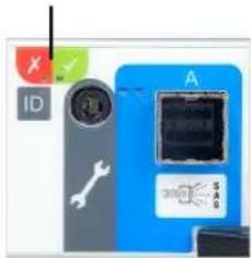
Table 2-14 Expansion I/O module icon and Status LED conditions
| Fault LED (amber)Activity LED | ||
| Module Fault(amber) | OnOff | The Expansion I/O module has encountered a fault condition.The Expansion I/O module is operating normally. |
| Power (green) | OnOff | The Expansion I/O module is on.The Expansion I/O module is off. |
| ID (blue) | On | The Expansion I/O module is being identified. |
Expansion I/O module SAS Activity LED location and conditions
This section discusses the location of the SAS Activity LEDs on the Expansion I/O modules and the SAS Activity LED conditions.
Figure 2-23 Expansion I/O module SAS Activity LED location
SAS Activity LED location

Table 2-15 Expansion I/O module SAS Activity LED conditions
| Fault LED (amber)Activity | ||
| OffOffNo Cable Present | ||
| All links up, no activity. | OffOnCable Present |
LED (g)
Table 2-15 Expansion I/O module SAS Activity LED conditions (continued)
| Fault LED (amber)Activity | ||
| Cable PresentAll links up. | activity | OffFlash with aggregate port |
| ■ Any fault which causes operation of the cable cease or fail to start For example, an OVERCURRENT trip.■ No connection detected at the opposite end of the SAS cable | to | OnOffCritical Fault |
| Non-Critical FaultAny fault which does not cause the connection to cease operation.For example, not all links established;OVERTEMPERATURE condition detected. | Flash with aggregate port activity | Flashing - One second on; one second off |
Veritas 5U84 Storage Shelf cooling modules
The Veritas 5U84 Storage Shelves include five cooling modules. The cooling modules provide cooling to the entire unit, which is suitable to maintain the internal component temperatures below each components maximum temperature limits.
Figure 2-24 Veritas 5U84 Storage Shelf cooling module components

Table 2-16 Veritas 5U84 Storage Shelf cooling module component locations
| ComponentNumber | |
| High performance, contra-rotating cooling fans1 | |
| Release latch2 | |
| Handle3 | |
| Mid-plane connector4 |
cooling modules provide:
■ Fast removal and replacement times without the need to turn off the storage shelf.
■ Electronic fan speed control to the fans.
■ Redundant serial interface connections to the rest of the storage shelf system.
■ Cooling module redundancy
■ Redundancy includes:
■ Maintaining the cooling function of the cooling module in the event of a single fan rotor failure.
- Maintaining the normal operation of the cooling module if one cooling control or fan controller module fails.
■ Automatically switching fan speeds to Full/High mode if the cooling module control unit fails.
- Maintaining the normal operation of the storage shelf for two minutes when a cooling module is swapped out due to a failure.
5U84 Storage Shelf Power Supply Units
Veritas 5U84 Storage Shelves includes dual Power Supply Units (PSU) that provide redundant power to the storage shelves. If one PSU fails, the storage shelves continue to operate as the second PSU continues to supply the storage shelf with power.
PSUs are hot-swappable. You can replace a faulty PSU while the storage shelf is running. However, you must complete the PSU replacement procedure within two minutes after you remove the faulty PSU.
Veritas 5U84 Storage Shelf chassis are keyed to prevent PSUs from being inserted upside down.
Figure 2-25 5U84 Storage Shelf Power Supply Unit

natural_image
3D rendering of a server rack with visible ports, connectors, and a power outlet (no text or symbols)The rear panel of the PSU includes a power switch, three status LEDs, and an AC socket for the power cord. The rear panel also includes a handle that you use during the PSU insertion and removal process.
Figure 2-26 5U84 Storage Shelf Power Supply Unit
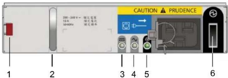
Table 2-17 5U84 Storage Shelf Power Supply Unit component locations
| ComponentNumber | |
| Release latch1 | |
| Handle2 | |
| PSU Fail LED3 | |
| AC Fail LED4 | |
| Power OK LED5 | |
| Power switch6 |
Veritas 5340 Appliance and 5U84 Storage Shelf cables
This chapter includes the following topics:
■ Power cables
■ Network cable
■ Multi-mode fiber optic cable
■ SAS3 cable
■ Twinaxial copper cables
Power cables
Each of the AC power modules in both the Veritas 5340 Appliance and the required Veritas 5U84 Primary Storage Shelf accept one AC power cable. The optional 5U84 Expansion Storage Shelf also uses one AC power cord in each of its AC power modules. One end of the AC power cable connects to the power supply on the appliance or the storage device. The other end of the cable connects to an external Power Distribution Unit (PDU) on the rack.
Power cables include a live line, a neutral line, and a grounding line.
Veritas 5340 Appliance AC power cable
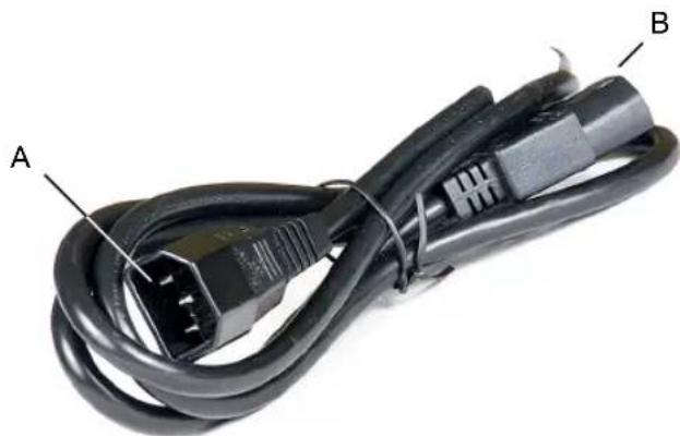
Figure 3-1 AC power cable - Veritas 5340 Appliance Appliance
natural_image
Close-up of a black electrical power cord with labeled connectors A and B (no text or symbols beyond labels)A AC power connector (IEC-60320-C14) to an external power supply such as a Power Distribution Unit (PDU) on a rack.
AC power connector (IEC-60320-C13) to an appliance.B
Cable rating: 15A 250V
Note: If your power distribution unit is not compatible with the IEC-60320-C14 plug, Veritas recommends that you purchase your power cable locally. Make sure that the power cable meets or exceeds the indicated power rating.
See "Flex 5340 Appliance compute node technical specifications" on page 74.
Veritas 5U84 Primary Storage Shelf / Expansion Storage Shelf AC power cable
Figure 3-2 AC power cable - Veritas 5U84 Primary Storage Shelf / Expansion Storage Shelf

natural_image
Close-up of two black electrical connectors labeled A and B, showing terminal blocks (no text or symbols beyond labels)A AC power connector (IEC-60320-C20) to an external power supply such as a Power Distribution Unit (PDU) on a rack.
AC power connector (IEC-60320-C19) to storage shelf.B
Cable rating: 20A 250V
Note: If your power distribution unit is not compatible with the IEC-60320-C20 plug, Veritas recommends that you purchase your power cable locally. Make sure that the power cable meets or exceeds the indicated power rating.
See "Veritas 5U84 Storage Shelf technical specifications" on page 77.
See "Network cable" on page 68.
See "Multi-mode fiber optic cable" on page 69.
See "SAS3 cable" on page 70.
See "Twinaxial copper cables" on page 71.
Network cable
The Flex Appliance appliance communicates with the Ethernet networks through an Ethernet network cable. One end of the network cable connects to the management network port or service network port of the appliance. The other end
of the cable connects to the network switch or an external gateway. Both ends of the cable are RJ45 connectors.
Figure 3-3 Network cable

natural_image
Blue wired network cable with two connectors (no text or symbols visible)See "Power cables" on page 66.
See "SAS3 cable" on page 70.
See "Twinaxial copper cables" on page 71.
Multi-mode fiber optic cable
A Flex Appliance Appliance compute node communicates with the required 5U84 Primary Storage Shelf through multi-mode fiber optic cables. One end of each fiber optic cable connects to PCIe-based 16Gb Fibre Channel host bus adapters that are installed in the compute node. The other end of the fiber optic cable connects to the 5U84 Primary Storage Shelf's 5005 RAID Controller. Both ends of the fiber optic cable use LC connectors.
Figure 3-4 Multi-Mode fiber cable

natural_image
Coiled light blue fiber optic cables with white connectors and yellow connectors (no text or symbols visible)Fiber optic cables require Small Form-factor Pluggable (SFP+) transceivers, which are provided with each device having Fibre Channel ports. The diagram shows the SFP, labeled 1, and the fiber optic cable which is attached to it, labeled 2.

natural_image
Pure diagram of a rectangular object with internal components and an arrow labeled '1' (no text or symbols beyond the label)
natural_image
Diagram of a dual-port network connector with labeled component 2 (no text or symbols beyond label)Supported SFPs are listed:
■ Finisar
■ JDSU
See "Power cables" on page 66.
See "Network cable" on page 68.
See "SAS3 cable" on page 70.
See "Twinaxial copper cables" on page 71.
SAS3 cable
SAS3 data cables are used to connect the 5U84 Primary Storage Shelf to an optional Veritas 5U84 Expansion Storage Shelf. SAS3 cables also connect multiple 5U84
Expansion Storage Shelves to each other. SAS3 cables have SAS3 connectors on both ends. Two SAS3 cables ship with each Veritas 5U84 Expansion Storage Shelf.
Figure 3-5
SAS3 cable
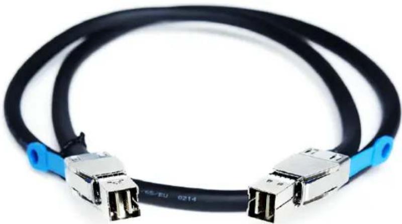
natural_image
Coiled black cable with metallic connectors and blue connectors (no text or symbols visible)See "Power cables" on page 66.
See "Network cable" on page 68.
See "Multi-mode fiber optic cable" on page 69.
See "Twinaxial copper cables" on page 71.
Twinaxial copper cables
The Flex Appliance appliance communicates with Ethernet networks that run the iSCSI protocol through high speed Twinaxial copper cables. If you configure the appliance to communicate with 10 Gb Ethernet iSCSI networks, these cables connect to the iSCSI card in the appliance.
These cables are also known as Direct-Access copper cables, and are available in 1-meter, 3-meter, or 5-meter lengths.

natural_image
Coiled black fiber optic cable with two interconnects (no visible text or symbols)See "Power cables" on page 66.
See "Network cable" on page 68.
See "Multi-mode fiber optic cable" on page 69.
See "SAS3 cable" on page 70.
Technical specifications, Environmental/Protocol standards, and Compliance standards
This appendix includes the following topics:
■ Flex 5340 Appliance compute node technical specifications
■ Veritas 5U84 Storage Shelf technical specifications
■ Environmental specifications
■ Protocol standards
■ Regulatory, compliance, and certification information
Flex 5340 Appliance compute node technical specifications
Table A-1 5340 Appliance compute node technical specifications
| 5340 Appliance compute nodeTechnical Specification | ||
| Rack information | 19" EIA standardThe rack rails that are provided for the 5340 Appliance compute node are extensible to 36" (91.44cm). This distance is the maximum depth that is allowed between rack posts. If the distance between rack posts is longer than 36" (91.44cm) the rails and the appliance cannot be properly installed. | |
| Two Intel Xeon 6138 CPUsProcessor | ||
| 2.0 GHz (Turbo: 3.7 GHz)CPU speed | ||
| 40 (20 per processor)Cores | ||
| 27.5 MB Cache L3Cache | ||
| Memory type and configuration (RDIMMs) | Base memory capacity: 768GB, expandable to 1.5TBMemory type: DDR4 RDIMMConfiguration: 32GB x 24 RDIMM modulesOperating voltage: 1.2VConfigured clock speed: 2666MHz | |
| YesSAS RAID mezzanine card | ||
| installed in a appliance compute node PCIe riser assembly | NoSAS RAID PCIe card | |
| RAID levels | RAID1 (mirroring) and RAID6 (block level striping with double distributed parity) are used as follows:■ RAID1: Veritas 5340 Appliance compute node system disksNote: RAID levels are generated using an onboard Intel RMSHC080 RAID controller that is installed in each of the 5340 Appliance compute nodes. | |
| Usable MSDP and AdvancedDisk storage capacity (TB) | AdvancedDisk storage capacity: up to 1920TBM SDP storage capacity: up to 916TBSee "Available appliance storage options" on page 38. | |
| Maximum number of storage shelves | 4One Veritas 5U84 Primary Storage Shelf; three Veritas 5U84 Expansion Storage Shelves. | |
| I/O portsSee “Available 5340 Appliance PCIe-based I/O configurations” on page 24.See “Total 5340 Appliance on-board and PCIe-based I/O ports” on page 26. | 16Gb Fibre Channel ports (PCIe-based) | 4Used to connect the 5340 Appliance compute nodes to the 5U84 Primary Storage Shelf |
| Ethernet/iSCSI-capable ports (PCIe-based) | Up to 10, depending on the appliance I/O configuration10Gb | |
| (PCIe-based) | Up to eight, depending on the appliance I/O configuration8Gb Fil | |
| (on-board) | 41Gb Ethernet ports | |
| Dimensions (IEC rack compliant) | Compute node:Height: 8.89cm (3.5") (approximately 2U)Width: 48.26cm (19)Depth: 79.38cm (31.25")5U84 Primary and 5U84 Expansion Storage Shelves:Height: 22.23cm (8.75") (approximately 5U - shelf, overall)Width: 48.26cm (19") (across the mounting flange)Length/depth: 93.35cm (36.75") (from rear of the front flanges to the rear extremity of the chassis)Note:The Veritas 5U84 Primary Storage Shelf and the 5U84 Expansion Storage Shelf are longer than what a standard IEC-compliant rack normally supports. Due to the additional length, the rack-based PDU hardware may need to be installed on the outside of the rack to accommodate the storage shelves. | |
| Appliance compute node: 23.26 kg (51.28 lbs)Maximum weight | ||
| Appliance compute node: 110 VAC - 220 VAC at 3.1 AAC power requirements | ||
| >90%Power factor | ||
| AC power cable | Specification: IEC-60320-C14 to IEC-60320-C13, 10A/250V, Black, 4 ftThe IEC-60320-C14 plugs into a Power Distribution Unit. The IEC-60320-C13 plugs into an appliance or storage shelf power supply.Note: If your power distribution unit is not compatible with the IEC-60320-C14 plug, then Veritas recommends that you purchase your power cable locally. Make sure the power cable meets or exceed the indicated power rating. | |
| 50/60HzAC Frequency range | ||
| Typical power consumption | Compute node:■ 300 watts | |
| with a maximum of four external storage shelves | 4,300 watts (2.2 watts per TB)Typical power consumption | |
| consumption with a maximum of four external storage shelves | 5,800 watts (3.0 watts per TB)Maximum power | |
| System cooling requirement(heat dissipation)(Appliance with maximum storage shelves attached) | Typical:■ 14,408 BTU/hourMaximum:■ 19,267 BTU/hour | |
| Operating voltage | 100V - 127 VAC200V - 240 VAC | |
| 90% +Power conversion efficiency | ||
| 70 dBAAcoustic noise | ||
See "Veritas 5U84 Storage Shelf technical specifications" on page 77.
See "Environmental specifications" on page 79.
See "Protocol standards" on page 80.
See "Regulatory, compliance, and certification information" on page 81.
Veritas 5U84 Storage Shelf technical specifications
The following table provides technical specifications for both the Veritas 5U84 Primary Storage Shelf and the Veritas 5U84 Expansion Storage Shelf.
Table A-2 Veritas 5U84 Primary Storage Shelf / 5U84 Expansion Storage Shelf technical specifications
| DescriptionTechnical specification | |
| Rack information | The rack installation height is the space occupied by a storage shelf in a rack cabinet. The shelf fits into a 5U rack space. Install the storage shelf in a rack cabinet that is 19 inches (483mm) wide. |
| Dimensions (IEC rack compliant) | Height: 21.97cm (8.65") (approximately 5U - shelf, overall)Width: 48.26cm (19") (across the mounting flange)Length/depth: 93.35cm (36.75") (from rear of the front flanges to the rear extremity of the chassis)Note:The Veritas 5U84 Primary Storage Shelf and the 5U84 Expansion Storage Shelf are longer than what a standard IEC-compliant rack normally supports. Due to the additional length, the rack-based PDU hardware may need to be installed on the outside of the rack to accommodate the storage shelves. |
| Hot swappable components | Disk drives, power supply units (PSUs), cooling modules, RAID Controllers, Expansion I/O modules |
| Usable storage capacity (TB) | Up to 1920TB, depending on the hardware configuration you purchaseSee “Available appliance storage options” on page 38. |
| 316.67 lb (143.64 Kg) -- includes disk drives and a rack kitMaxim | |
| Dual ported 12Gb/s SASDevice types supported | |
| shelf | 84Maximum drives per storage |
| Typical power consumption | 1000 watts per storage shelfNote:You can connect a maximum of four storage shelves to the 5340 Appliance compute nodes. |
| Supported RAID level | RAID6 and RAID10: 5U84 Primary Storage Shelf and 5U84 Expansion Storage Shelf data storage disks |
| Controllers | 5U84 Primary Storage Shelf: Dual RealStor 5005 16Gb Fibre Channel RAID controllers per storage shelf5U84 Expansion Storage Shelf: Dual Storage Bridge Bay (SBB) 2.1 compatible Expansion I/O modules per storage shelf |
| Host/Expansion Interface | Three universal x4 12Gb mini-SAS connectors (SFF-8644) per Expansion I/O module |
| Maximum output power | 1300 watts maximum continuous output power at high line voltageYou can connect up to four storage shelves to the 5340 Appliance compute nodes. |
| 6.67 A at 200 - 240 VACAC power requirements | |
| 200V - 240 VACOperating voltage | |
| 50/60HzAC Frequency range | |
| Power conversion efficiency | 81% @ 10% load89% @ 20% load93% @ 50% load90% @ 100% load |
| Temperature Range | Operating: 5° to 35°C (de-rate 5°C above 2,133m (7,000')) (41°F TO 95°F)Non-operating: -40°C to 70°C (-40°F TO 158°F) |
| Relative humidity | Operating: 20%rh to 80%rh non-condensingNon-operating: 5%rh to 100%rh non-condensing |
| Sound Power Operating ≤ 8.0 Bels LWAd @ 23°Acoustic noise | |
| Operating altitude | -30 to 3048m (-100 to 10000ft)De-rate 5°C above 2134m (7000ft) |
| -305 to 12192m (-1000 to 40000ft)Non-operating altitude |
Table A-2 Veritas 5U84 Primary Storage Shelf / 5U84 Expansion Storage Shelf technical specifications (continued)
| DescriptionTechnical specification | |
| 0.21gRMS 5-500Hz RandomOperational vibration | |
| 5g10ms 12 SineOperational shock | |
| (Non-operational) | 0.3g2-200-2Hz Swept Sine.Relocation vibration |
| 1.04 gRMS 2-200Hz Random.Non-operational vibration | |
| Non-operational shock | 30g10ms 12 Sine (Z-axis)20g10ms 12 Sine(X-and Y-axes) |
See "Flex 5340 Appliance compute node technical specifications" on page 74.
See "Environmental specifications" on page 79.
See "Protocol standards" on page 80.
See "Regulatory, compliance, and certification information" on page 81.
Environmental specifications
Table A-3 Veritas Appliance / Veritas 5U84 Primary/Expansion Storage Shelf environmental specifications
| Specification | Veritas 5340 Appliance / 5U84 Primary/Expansion Storage Shelf |
| ASHRAE A2 (10°C to 35°C) (50°F to 95°F)Operating temperature | |
| Non-operating temperature | -25°C to 70°C (-14°F to 158°F)The non-operating temperature is defined as the temperature of the system when the system is turned off. It is also referred to as the storage temperature.Veritas recommends that you do not store the system in an environment where the temperatures fall outside of the listed temperature range. |
| (RH) | 20% RH to 80% RHOperating humidity |
| humidity | 8% RH to 90% RHNon-operating |
| (feet) | -30 to 3000 m with ASHRAE A2 class derating (0 to 10,000 ft)Operating |
| (per hour) | 10°C/h (50°F/h)Temperature gradient |
See "Flex 5340 Appliance compute node technical specifications" on page 74.
See " Veritas 5U84 Storage Shelf technical specifications" on page 77.
See "Protocol standards" on page 80.
See "Regulatory, compliance, and certification information" on page 81.
Protocol standards
The following table provides standards with which the Veritas 5340 Appliance and the Veritas 5U84 Primary/Expansion Storage Shelf comply.
Table A-4 Veritas Appliance / Veritas 5U84 Primary/Expansion Storage Shelf standards compliance
| VersionStandard | |
| IPMI 2.0 | Intelligent Platform Management Interface Specification Second Generation v2.0, Document Revision 1.0 |
| SMBIOS | System Management BIOS (SMBIOS) Reference Specification, Version 2.5 |
| SAS3SAS | |
| ACPI | Advanced Configuration and Power Interface Specification, Revision 3.0, September 2 |
| RFC0791: Internet ProtocolIP | |
| INCITS T11 (X3T9.3)FC | |
| PCIe 3.0PCIe |
See "Flex 5340 Appliance compute node technical specifications" on page 74.
See "Veritas 5U84 Storage Shelf technical specifications" on page 77.
See "Environmental specifications" on page 79.
See "Regulatory, compliance, and certification information" on page 81.
Regulatory, compliance, and certification information
The following sections give information about the product regulations and compliance.

WARNING
To ensure regulatory compliance, you must adhere to the assembly instructions in this guide to ensure and maintain compliance with existing product certifications and approvals. Use only the described, regulated components that are specified in this guide. Use of other products or components voids the UL listing and other regulatory approvals of the product. The result is noncompliance with product regulations in the region(s) in which the product is sold.
Before computer integration make sure that the appliance, power supply, and other modules have passed EMC testing. This process helps to ensure EMC compliance with your local regional rules and regulations. The testing is done using a server board with a microprocessor from the same family (or higher) and operating at the same (or higher) speed as the microprocessor that is used on this server board. The final configuration of your appliance product may require additional EMC compliance testing.
This product is an FCC Class A device. Integration of it into a Class B system does not result in a Class B device.
Product regulatory compliance
The NetBackup appliance, when correctly integrated per this guide, complies with the following safety and electromagnetic compatibility (EMC) regulations.
Intended Application - This product was evaluated as Information Technology Equipment (ITE), which may be installed in offices, schools, computer rooms, and similar commercial type locations. The suitability of this product for other product categories and environments, other than an ITE application, may require further evaluation. Other product categories and environments may include medical,
industrial, telecommunications, NEBS, residential, alarm systems, and test equipment.
Product safety compliance
The following is a list of product safety compliance norms for different countries:
■ UL60950 - CSA 60950 (USA / Canada)
■ EN60950 (Europe)
■ IEC60950 (International)
■ CB Certificate & Report, IEC60950 (report to include all country national deviations)
■ GS Certification (Germany)
■ GOST R 50377-92 - Certification (Russia)
■ Belarus Certification (Belarus)
■ Ukraine Certification (Ukraine)
■ CE - Low Voltage Directive 73/23/EEE (Europe)
■ IRAM Certification (Argentina)
■ GB4943- CNCA Certification (China)
Product EMC Compliance - Class A Compliance
The following is a list of EMC compliance norms for different countries:
■ FCC /ICES-003 - Emissions (USA/Canada) Verification
■ CISPR 22 - Emissions (International)
■ EN55022 - Emissions (Europe)
■ EN55024 - Immunity (Europe)
■ EN61000-3-2 - Harmonics (Europe)
■ EN61000-3-3 - Voltage Flicker (Europe)
■ CE - EMC Directive 89/336/EEC (Europe)
■ VCCI Emissions (Japan)
■ AS/NZS 3548 Emissions (Australia / New Zealand)
■ BSMI CNS13438 Emissions (Taiwan)
■ GOST R 29216-91 Emissions (Russia)
■ GOST R 50628-95 Immunity (Russia)
■ Belarus Certification (Belarus)
■ Ukraine Certification (Ukraine)
■ GB 9254 - CNCA Certification (China)
■ GB 17625 - (Harmonics) CNCA Certification (China)
Product ecology compliance
Use of banned substances are restricted in accordance with world-wide regulatory requirements. A Material Declaration Data Sheet is available.
■ Use of banned substances are restricted in accordance with world-wide regulatory requirements. A Material Declaration Data Sheet is available.
■ Quantity limit of 0.1% by mass (1000 PPM) for: Lead, Mercury, Hexavalent Chromium, Polybrominated Biphenyls Diphenyl-Ethers (PBB/PBDE)
■ Quantity limit of 0.01% by mass (100 PPM) for: Cadmium
■ California Code of Regulations, Title 22, Division 4.5, Chapter 33: Best Management Practices for Perchlorate Materials
■ China - Restriction of Hazardous Substances (China RoHS)
■ WEEE Directive (Europe)
■ Packaging Directive (Europe)
Certifications / Registrations / Declarations
The following is a list of the required certifications, registrations, and declarations:
■ NRTL Certification (US/Canada)
■ CE Declaration of Conformity (CENELEC Europe)
■ FCC/ICES-003 Class A Attestation (USA/Canada)
■ VCCI Certification (Japan)
■ C-Tick Declaration of Conformity (Australia)
■ MED Declaration of Conformity (New Zealand)
■ BSMI Certification (Taiwan)
■ GOST R Certification / Certification (Russia)
■ Belarus Certification / Certification (Belarus)
■ IRAM Certification (Argentina)
■ CNCA CCC Certification (China)
■ Ecology Declaration (International)
■ China RoHS Environmental Friendly Use Period
■ Packaging & Product Recycling Marks
Electromagnetic compatibility notices
The following sections list the compatibility notices for USA, Canada, Europe, Japan, and Taiwan.
FCC Verification Statement (USA)
This device complies with Part 15 of the FCC Rules. Operation is subject to the following two conditions: (1) this device may not cause harmful interference, and (2) this device must accept any interference received, including interference that may cause undesired operation.
This equipment has been tested and found to comply with the limits for a Class A digital device, pursuant to Part 15 of the FCC Rules. These limits are designed to provide reasonable protection against harmful interference in a residential installation. This equipment generates, uses, and can radiate radio frequency energy. If the equipment is not installed and used in accordance with the instructions, it may cause harmful interference to radio communications. However, there is no guarantee that interference will not occur in a particular installation. If this equipment does cause harmful interference to a radio or a television reception (can be determined by turning the equipment off and on), the user is encouraged to try to correct the interference by one or more of the following measures:
■ Reorient or relocate the receiving antenna.
■ Increase the separation between the equipment and the receiver.
- Connect the equipment to an outlet on a circuit other than the one to which the receiver is connected.
- Consult the dealer or an experienced radio/TV technician for help. Any changes or modifications not expressly approved by the grantee of this device can void the user's authority to operate the equipment. The customer is responsible to ensure the compliance of the modified product. Only peripherals (computer input or output devices, terminals, printers, etc.) that comply with FCC Class A or B limits may be attached to this product. Operation with noncompliant peripherals is likely to result in interference to radio and TV reception. All cables that are used to connect to peripherals must be shielded and grounded. Operation with
Regulatory and compliance information 65 Electromagnetic compatibility notices the cables that are connected to peripherals that are not shielded and grounded may result in interference to radio and TV reception.
ICES-003 (Canada)
English translation of the notice above:
This digital apparatus does not exceed the Class A limits for radio noise emissions from the digital apparatus that is set out in the interference-causing equipment standard entitled: "Digital Apparatus," ICES-003 of the Canadian Department of Communications.
CE Declaration of Conformity (Europe)
This product has been tested in accordance to, and complies with the Low Voltage Directive (73/23/EEC) and EMC Directive (89/336/EEC). The product has been marked with the CE Mark to illustrate its compliance.
VCCI (Japan)
This is a Class A product based on the standard of the Voluntary Control Council for Interference (VCCI) from Information Technology Equipment. If the product is used near a radio or a television receiver in a domestic environment, it may cause radio interference. Install and use the equipment according to the instruction manual.
BSMI (Taiwan)
The BSMI Certification Marking and EMC warning label is located on the outside rear area of the product.
Symbols
24
16Gb Fibre Channel HBA 27
5340 appliance compute node
disk drive layout 12
5U84 Expansion Storage Shelf
about 37
control panel 52
control panel functions 53
drawer Sideplane hot swap LED indicators 50
drawer Sideplane Status panels 48
Expansion I/O modules 60
components and locations 61
printed circuit board (PCB) assembly 46
rear components 53
component locations 55
technical specifications 77
5U84 Expansion Storage Shelf serial number
location 12
5U84 Primary Storage Shelf
about 37
control panel 52
control panel functions 53
cooling module components 63
cooling modules 63
component locations 64
drawer Sideplane hot swap LED indicators 50
drawer Sideplane Status panels 48
printed circuit board (PCB) assembly 46
RAID controller 56
components and locations 56
rear components 53
component locations 54
technical specifications 77
5U84 Primary Storage Shelf serial number location
5U84 Storage Shelf Power Supply Units (PSU) 64
component locations 65
5U84 Storage Shelves
about 37
core components 37
disk drive drawers 41
5U84 Storage Shelves (continued)
Disk Drive In Carrier (DDIC) modules 43
components and locations 45
disk drive slot numbering 42
plug-in modules 37
printed circuit board (PCB) assembly
Baseplane cards 46
Sideplane cards 46
storage options 38
supported RAID levels 37
8Gb Fibre Channel HBA 31
A
Access 3340 Appliance
features
RAID levels 7
appliance
power button LED 20
system memory configuration 8
C
Cable connection types
Direct-attach / Twinaxial 26
fiber optic 26
cables
multi-mode fiber optic
description 69
network
description 68
power
description 66
SAS3
description 70
12Compute node
control panel 15
Power button LED states 20
system Status LED indicator 17
disk drive LED indicators 14
disk drive LEDs 14
front panel USB port 15
Compute node (continued)
rear panel
features and connectors 21
compute node serial number location 12
Control panel
5U84 Expansion Storage Shelf 52
control panel functions 53
5U84 Primary Storage Shelf 52
control panel functions 53
compute node 15
power button LED states 20
system LED descriptions 15
system Status LED indicator 17
D
DIMM
system memory configuration 7
Disk drive drawers
5U84 Storage Shelves 41
Disk Drive In Carrier (DDIC) modules
5U84 Storage Shelves 43
components and locations 45
disk drive layout
appliance compute node 12
disk drive LED indicators
compute node 14
disk drive LEDs
compute node indicators 14
Disk drive slot numbering
5U84 Storage Shelves 42
Drawer Sideplane hot swap LED indicators
5U84 Expansion Storage Shelf 50
LED indicator statuses 51
5U84 Primary Storage Shelf 50
LED indicator statuses 51
E
Environmental specifications
Veritas Appliance / Veritas 5U84
Primary/Expansion Storage Shelf 79
eth ports 33
Expansion I/O modules
5U84 Expansion Storage Shelf 60
components and locations 61
Veritas 5U84 Expansion Storage Shelf
LED location and conditions 61
F
FC HBA LED status lights 31
16Gb Fibre channel HBA 27
Fibre Channel card 27, 31
|
I/O configurations
standard available options 24
I/O ports
on-board 26
PCI-based 26
total number of 26
L
LED descriptions
Veritas 5340 Appliance
system status 17
LED indicator status
Fibre Channel HBA 29, 32
LED location and conditions
Expansion I/O modules
Veritas 5U84 Expansion Storage Shelf 61
N
Network interface port locations and speeds 33
P
PCIe add-in cards
16Gb Fibre Channel HBA 27
8Gb Fibre Channel HBA 31
specifications
QLE2562 dual-port 8Gb FC HBA 31
QLE2592 dual-port 16Gb FC HBA 27
PCIe-based slot configurations
standard available configurations 24
power button LED
appliance 20
descriptions 20
Power button LED states
compute node
control panel 20
Power Supply Units
5U84 Storage Shelf 64
5U84 Storage Shelf Power Supply Units (PSU)
component locations 65
Printed circuit board (PCB) assembly
5U84 Storage Shelves
Baseplane cards 46
components 46
Sideplane cards 46
processor type 7
protocol standards
Veritas Appliance / Veritas 5U84
Primary/Expansion Storage Shelf 80
Q
QLE8442 dual-port 10Gb Ethernet card dual-port 30
R
RAID controller 56
component locations 57
RAID levels 7
supported 37
Rear panel
5U84 Expansion Storage Shelf
components 53
5U84 Primary Storage Shelf
components 53
compute node
features and connectors 21
S
SAS Activity LED location and conditions
Expansion I/O modules
Veritas 5U84 Expansion Storage Shelf 62
serial number locations
5U84 Expansion Storage Shelf 12
5U84 Primary Storage Shelf 12
compute node 12
Sideplane Status panels
5U84 Storage Shelves 48
descriptions 49
locations 48
statuses 50
Status LED indicator
compute node control panel 17
Storage options
by disk drive capacities 39
Veritas 5340 Appliance system 38
system status
Veritas 5340 Appliance
LED descriptions 17
system status LED location
Veritas 5340 Appliance
control panel 17
T
Technical specifications
Veritas 5U84 Storage Shelf 77
technical specifications
Veritas 5340 Appliance compute node 74
U
USB port
compute node front panel location 15
V
Veritas 5340 Appliance
control panel
system status LED location 17
features
RAID levels 7
system memory configuration (DIMMS) 7
Veritas 5340 Appliance storage options 38
Veritas 5U84 Expansion Storage Shelf
Expansion I/O modules
LED location and conditions 61
SAS Activity LED location and conditions 62
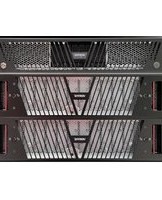
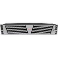
- Veritas 5340 Appliance Product Description
- Technical Support
- Documentation
- Documentation feedback
- Veritas Services and Operations Readiness Tools (SORT)
- Chapter 1 About the Veritas 5340 Appliance .... 6
- Chapter 2 About the Veritas 5U84 Storage Shelves ...... 36
- Chapter 3 Veritas 5340 Appliance and 5U84 Storage Shelf cables 66
- Appendix A Technical specifications, Environmental/Protocol standards, and Compliance standards 73
- Index 86
- About the Veritas 5340 Appliance
- Features and components of the appliance
- Locating the appliance serial number
- About 5340 Appliance compute node disk dr configurations
- About the 5340 Appliance compute node disk drive LEDs
- About the 5340 Appliance compute node from panel USB port
- About the 5340 Appliance control panel
- About the System Status LED states
- About the Power button LED states
- About the appliance compute node rear pane
- Available 5340 Appliance PCIe-based I/O configurations
- Total 5340 Appliance on-board and PCIe-based I/O ports
- QLE2692 dual-port 16Gb Fibre Channel host bus adap
- QLE8442 dual-port 10Gb Ethernet/iSCSI capable card wi SFP+ modules
- QLE2562 dual-port 8Gb Fibre Channel host bus adapted with SFP+ modules
- Appliance on-board network interface port locations and speeds
- About the Veritas 5U84 Storage Shelves
- About Veritas 5340 Appliance storage shelves
- Available appliance storage options
- About the Veritas 5U84 Storage Shelf disk drive drawers
- Disk drive drawers
- Disk drive slot numbering
- Disk Drive In Carrier (DDIC) modules
- Disk Drive Drawer printed circuit board (PCB) assemb
- Drawer Sideplane Status panels
- Drawer Sideplane hot swap LED indicators
- 5U84 Primary Storage Shelf and the 5U84 Expansion Storage Shelf control panel
- About the 5U84 Primary Storage Shelf and Expansion Storage Shelf rear components
- 5U84 Primary Storage Shelf
- 5U84 Expansion Storage Shelf
- Veritas 5U84 Primary Storage Shelf RAID Controllers
- Veritas 5U84 Expansion Storage Shelf Expansion I/O modules
- Expansion I/O module Status LED location and condition
- Expansion I/O module SAS Activity LED location and conditions
- Veritas 5U84 Storage Shelf cooling modules
- 5U84 Storage Shelf Power Supply Units
- Veritas 5340 Appliance and 5U84 Storage Shelf cables
- Power cables
- Veritas 5340 Appliance AC power cable
- Veritas 5U84 Primary Storage Shelf / Expansion Storage Shelf AC power cable
- Network cable
- Multi-mode fiber optic cable
- SAS3 cable
- Twinaxial copper cables
- Technical specifications, Environmental/Protocol standards, and Compliance standards
- Flex 5340 Appliance compute node technical specifications
- Veritas 5U84 Storage Shelf technical specifications
- Environmental specifications
- Protocol standards
- Regulatory, compliance, and certification information
- WARNING
- Product regulatory compliance
- Product safety compliance
- Product EMC Compliance - Class A Compliance
- Product ecology compliance
- Certifications / Registrations / Declarations
- Electromagnetic compatibility notices
- FCC Verification Statement (USA)
- ICES-003 (Canada)
- CE Declaration of Conformity (Europe)
- VCCI (Japan)
- BSMI (Taiwan)
- Symbols
- A
- C
- D
- E
- F
- |
- L
- N
- P
- Q
- R
- S
- T
- U
- V
Brand : VERITAS
Model : NetBackup Flex 5340
Category : Server