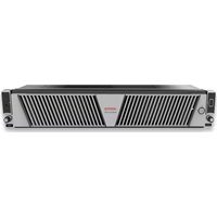
5250 - Server VERITAS - Free user manual and instructions
Find the device manual for free 5250 VERITAS in PDF.


| Type of Product | Server |
| Brand | Veritas |
| Model | 5250 |
| Form Factor | Rack-mountable (2U) |
| Dimensions (W x D x H) | 483 x 700 x 88 mm |
| Weight | 18 kg |
| Power Supply | Dual redundant 800W PSU |
| Input Voltage | 100-240 V AC, 50/60 Hz |
| Processor | Intel Xeon Scalable (2nd Gen) |
| Memory | Up to 256 GB DDR4 ECC |
| Storage | Up to 8 x 2.5" hot-swap bays |
| Network Interfaces | 2 x 10GbE RJ45 |
| Operating Temperature | 10°C to 35°C |
| Storage Temperature | -40°C to 70°C |
| Relative Humidity | 20% to 80% non-condensing |
| Main Functions | Data processing, virtualization, storage management, networking |
| Safety Features | Overvoltage protection, thermal shutdown, chassis intrusion detection |
| Maintenance | Periodic dust removal, fan and filter cleaning, software updates |
| Spare Parts Availability | Hard drives, power supplies, fans, memory modules available |
| Repairability Index | 8/10 - Modular and hot-swappable components |
Frequently Asked Questions - 5250 VERITAS
User questions about 5250 VERITAS
0 question about this device. Answer the ones you know or ask your own.
Ask a new question about this device
Download the instructions for your Server in PDF format for free! Find your manual 5250 - VERITAS and take your electronic device back in hand. On this page are published all the documents necessary for the use of your device. 5250 by VERITAS.
USER MANUAL 5250 VERITAS
Veritas™ 5250 Appliance Product Description Guide
Veritas 5250 Appliance Product Description Guide
Last updated: 2023-02-07
Document version: Revision 1.1
Legal Notice
Copyright © 2023 Veritas Technologies LLC. All rights reserved.
Veritas, the Veritas Logo, and NetBackup are trademarks or registered trademarks of Veritas Technologies LLC or its affiliates in the U.S. and other countries. Other names may be trademarks of their respective owners.
This product may contain third-party software for which Veritas is required to provide attribution to the third party (“Third-party Programs”). Some of the Third-party Programs are available under open source or free software licenses. The License Agreement accompanying the Software does not alter any rights or obligations you may have under those open source or free software licenses. Refer to the Third-party Legal Notices document accompanying this Veritas product or available at:
https://www.veritas.com/about/legal/license-agreements
The product described in this document is distributed under licenses restricting its use, copying, distribution, and decompilation/reverse engineering. No part of this document may be reproduced in any form by any means without prior written authorization of Veritas Technologies LLC and its licensors, if any.
THE DOCUMENTATION IS PROVIDED "AS IS" AND ALL EXPRESS OR IMPLIED CONDITIONS, REPRESENTATIONS AND WARRANTIES, INCLUDING ANY IMPLIED WARRANTY OF MERCHANTABILITY, FITNESS FOR A PARTICULAR PURPOSE OR NON-INFRINGEMENT, ARE DISCLAIMED, EXCEPT TO THE EXTENT THAT SUCH DISCLAIMERS ARE HELD TO BE LEGALLY INVALID. VERITAS TECHNOLOGIES LLC SHALL NOT BE LIABLE FOR INCIDENTAL OR CONSEQUENTIAL DAMAGES IN CONNECTION WITH THE FURNISHING, PERFORMANCE, OR USE OF THIS DOCUMENTATION. THE INFORMATION CONTAINED IN THIS DOCUMENTATION IS SUBJECT TO CHANGE WITHOUT NOTICE.
The Licensed Software and Documentation are deemed to be commercial computer software as defined in FAR 12.212 and subject to restricted rights as defined in FAR Section 52.227-19. "Commercial Computer Software - Restricted Rights" and DFARS 227.7202, et seq. "Commercial Computer Software and Commercial Computer Software Documentation," as applicable, and any successor regulations, whether delivered by Veritas as on premises or hosted services. Any use, modification, reproduction release, performance, display or disclosure of the Licensed Software and Documentation by the U.S. Government shall be solely in accordance with the terms of this Agreement.
Veritas Technologies LLC
2625 Augustine Drive
Santa Clara, CA 95054
http://www.veritas.com
Technical Support
Technical Support maintains support centers globally. All support services will be delivered in accordance with your support agreement and the then-current enterprise technical support policies. For information about our support offerings and how to contact Technical Support, visit our website:
https://www.veritas.com/support
You can manage your Veritas account information at the following URL:
https://my.veritas.com
If you have questions regarding an existing support agreement, please email the support agreement administration team for your region as follows:
CustomerCare@veritas.comWorldwide (except Japan)
CustomerCare_Japan@veritas.comJapan
Documentation
Make sure that you have the current version of the documentation. Each document displays the date of the last update on page 2. The latest documentation is available on the Veritas website:
https://www.veritas.com/content/support/en_US/dpp.Appliances.html
Documentation feedback
Your feedback is important to us. Suggest improvements or report errors or omissions to the documentation. Include the document title, document version, chapter title, and section title of the text on which you are reporting. Send feedback to:
APPL.docs@veritas.com
You can also see documentation information or ask a question on the Veritas community site:
http://www.veritas.com/community/
Veritas Services and Operations Readiness Tools (SORT)
Veritas Services and Operations Readiness Tools (SORT) is a website that provides information and tools to automate and simplify certain time-consuming administrative tasks. Depending on the product, SORT helps you prepare for installations and upgrades, identify risks in your datacenters, and improve operational efficiency. To see what services and tools SORT provides for your product, see the data sheet:
https://sort.veritas.com/data/support/SORT_Data_Sheet.pdf
Chapter 1 About the Veritas 5250 Appliance .... 6
Veritas 5250 Appliance overview 6
Features and components of the Veritas 5250 Appliance .... 8
Locating the appliance serial number 10
Veritas 5250 Appliance front panel disk drive configurations .... 10
About the disk drive LEDs 12
About the Veritas 5250 Appliance front panel USB port 13
About the 5250 Appliance control panel 13
About the System Status LED states 15
About the Power button LED states 18
About the 5250 Appliance rear panel 19
Veritas 5250 Appliance I/O configuration options 23
Veritas 5250 Appliance total I/O on-board and PCIe ports ...... 24
Available I/O configurations by slot for Veritas 5250 Appliance installations 25
QLE2692 dual-port 16Gb Fibre Channel host bus adapter ...... 26
Mellanox ConnectX-4 Lx EN MCX4121A-ACAT Ethernet card 29
Broadcom P225p 10/25Gb PCIe Ethernet card 30
Intel X550-T2 dual-port 10Gb Ethernet card 31
Intel RAID Adapter RS3P4MF088F 33
Chapter 2 Veritas 2U12 65.5TiB/72TB Storage Shelf .... 35
Storage Shelf overview 35
Usable appliance storage capacities 37
Components of the S Series Storage Shelf 38
S Series Storage Shelf front panel components 38
S Series Storage Shelf control panel 40
S Series Storage Shelf rear components 42
S Series Storage Shelf I/O modules 43
S Series I/O module Status LED location and conditions 45
S Series I/O module SAS Activity LED location and conditions 46
S Series Storage Shelf Power Cooling Modules 47
S Series Power Cooling Module LEDs 49
Components of the D Series Storage Shelf 51
D Series Storage Shelf front panel components 51
D Series Storage Shelf control panel 53
D Series Storage Shelf rear components 54
D Series Power indicator codes 55
Chapter 3 Veritas 5250 Appliance and Veritas 2U12 65.5TiB/72TB Storage Shelf cables .... 57
Power cables 57
Network cable 58
Multi-Mode fiber optic cable 59
Twinaxial copper cables 60
SAS-3 cable 61
Appendix A Technical specifications, Environmental/Protocol standards, and Compliance standards 63
Veritas 5250 Appliance technical specifications 64
Veritas S Series 2U12 65.5TiB/72TB Storage Shelf technical specifications 66
Veritas D Series 2U12 65.5TiB/72TB Storage Shelf technical specifications 68
Environmental specifications 70
Protocol standards 71
Regulatory, compliance, and certification information 71
Product regulatory compliance 72
Country approvals 72
Product safety compliance 73
Product EMC Compliance - Class A Compliance 73
Product environmental compliance 74
Index 75
About the Veritas 5250 Appliance
This chapter includes the following topics:
■ Veritas 5250 Appliance overview
■ Features and components of the Veritas 5250 Appliance
■ Locating the appliance serial number
■ Veritas 5250 Appliance front panel disk drive configurations
■ About the Veritas 5250 Appliance front panel USB port
■ About the 5250 Appliance control panel
■ About the 5250 Appliance rear panel
■ Veritas 5250 Appliance I/O configuration options
Veritas 5250 Appliance overview
Figure 1-1 NetBackup 5250 Appliance

natural_image
Front view of a server rack with ventilation grilles and indicator lights (no visible text or symbols)Figure 1-2 Flex 5250 Appliance

natural_image
Front view of a server rack with two grilles and indicator lights (no visible text or symbols)The Veritas 5250 Appliance is a hardware and software storage system that can scale to 429.4 TiB of available backup capacity. It consists of a Veritas 5250 Appliance and up to six optional Veritas 2U12 65.5TiB/72TB storage shelves. By itself, the 2U Veritas5250 Appliance offers internal storage from 9.1 TiB to 36.4 TiB, depending on the appliance configuration purchased.
A Veritas 2U12 65 B storage shelf offers 65.5 TiB of storage. Attaching six storage shelves offers 429.4 TiB of storage. As with previous generations of the NetBackup 52xx appliances, the Veritas 5250 Appliance can be configured as a primary server or a media server. It can also be configured as both. The 5250 Appliance supports both S Series and D Series storage shelves.
See "Usable appliance storage capacities" on page 37.
SAS-3 cables connect the Veritas 5250 Appliance to the storage shelves. SAS-3 cables also connect the storage shelves to each other.
The Veritas 5250 Appliance supports the following software:
■ NetBackup Appliance software release 3.2 (revised) and above
Note: This model uses a revised version of software release 3.2. This revised software version contains specific support for the 5250 hardware and the related software functionality that is not included in the previous 3.2 release. The minimum supported software version for the 5250 appliance is the revised 3.2 version that is shipped with each unit. If a re-image is ever necessary, you must use the revised 3.2 software version.
■ Flex Appliance 2.0.1 and above
About Veritas 5250 Appliance configurations
To determine the right Veritas 5250 Appliance system for your environment, you should consider the environment's future storage requirements over the lifetime of the system.
Veritas offers multiple I/O configurations from which to choose. You can use the supported Veritas 5250 Appliance I/O configurations to best serve the needs of your particular environment.
These configurations include the following:
■ One Veritas 5250 Appliance with 9.1 TiB of internal storage only
■ One Veritas 5250 Appliance with 36.4 TiB of internal storage only
■ One Veritas 5250 Appliance with up to six external 65.5TiB/72TB storage shelves for a total of 429.4 TiB of storage
If your environment requires more than 36TiBs of storage, consider the Veritas 5250 Appliance with 9.1TiBs of internal storage and one 65.5TiB/72TB Veritas 2U12 65.5TiB/72TB Storage Shelf. If more storage is required, you can add up to five additional 65.5TiB/72TB storage shelves to this configuration.
Features and components of the Veritas 5250 Appliance
This section describes the features and components of the Veritas 5250 Appliance.
Table 1-1 Veritas 5250 Appliance features
| DescriptionFeature | |
| Two (2) Intel® Scalable 4214 2.2 GHz processorsProcessor | |
| Appliance software version | NetBackup Appliance 3.2 (revised) or aboveFlex Appliance 2.0.1 or aboveNote: For the latest NetBackup Appliance compatibility information, refer to the NetBackup Hardware Compatibility List posted on the following site:http://www.veritas.com/docs/000033647 |
| Performance and capacity | Supports high-performance processors with low-power consumption.Provides high-capacity intra-appliance switching bandwidth, along with high I/O throughput.Available internal storage capacities of 9 TB, or 36 TB without optional external storage shelves. The available capacity can be allocated either in part or in whole to a deduplication pool or to an AdvancedDisk pool (non-deduplicated storage). |
| System memory configuration (DIMMS) | 64GB, up to a maximum of 512GBNote: When you purchase the first expansion storage shelf, the Storage Expansion kit that comes with the storage shelf includes a replacement of 256GB memory. A Memory Expansion kit containing eight 32GB DIMM memory chip is needed to support the fifth storage shelf. |
| Space reduction | The deduplication engine provides up to 100 times reduction in storage. The client-side plug-in provides similar levels of bandwidth reduction. |
| Scalable architecture | Due to fingerprinting and RAID redundancy, the overall storage capabilities are not a simple multiplication of the disk size and the total number of disks. |
| High availability | Supports redundant hot-swappable disks and power modules. |
| RAID levels | RAID 1 (standard mirroring) and RAID 6 (block level striping with double distributed parity) are implemented as follows:■ Appliance system disks: RAID 1■ Appliance storage disks: RAID 6■ Storage shelf data storage disks: RAID 6Note: The disk drives in the appliance are pre-formatted before the appliance is shipped. These drives should not be moved into different slots or otherwise rearranged. |
| Fibre Channel support | The Veritas 5250 Appliance can be ordered with one, two, three or four PCIe 16 Gb Fibre Channel host bus adapter cards preinstalled.See "Available I/O configurations by slot for Veritas 5250 Appliance installations" on page 25. |
| PCIe 10/25 Gb Ethernet cards | PCIe 10/25 Gb Ethernet cards with Fibre Optic ports are available. |
| See "About the 5250 Appliance rear panel" on page 19.Rear par | |
| Additional storage | YesYou can attach up to six optional storage shelves to the Veritas 5250 Appliance. Depending on the appliance configuration you purchase, a total of 429.4 TB of usable storage capacity is available.See "Usable appliance storage capacities" on page 37. |
Locating the appliance serial number
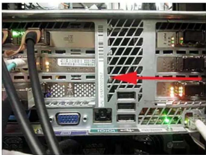
A vertical bar on the rear panel of the appliance contains the serial number.

natural_image
Interior view of a computer drive bay showing internal components like CPU socket, drive bays, and network (no readable text or symbols)You can also find the serial number in the pull-out plastic tab located at the front-left-hand of the chassis.
Veritas 5250 Appliance front panel disk drive configurations
The Veritas 5250 Appliance contains 12 SAS hard disk drives, which can be accessed from the appliance's front panel. An embedded RAID controller on the appliance's mainboard is used to configure four of the 12 disks into two RAID1 mirrored volumes. These volumes are labeled Volume0 and Volume1.
The disk drives that are located in slot 0 and slot 1 are configured as the RAID1, VOLUME0 device. These disk drives contain the appliance operating system and the NetBackup/Flex application. You can hot-swap one of these disk drives at a time; however, you cannot operate the appliance if both disk drives are removed.
The disk drives in slot 2 and slot 3 are configured as the RAID1, VOLUME1 device. These disk drives store all of the log files.
The disk drives in slots 4 through 10 store user data. They are configured as a RAID 6 array, which uses block-level striping with two parity blocks across each of the disk drives in the volume.
The appliance uses the disk drive that is located in slot 11 as a hot-spare disk. If one of the disk drives fails in slots 4 through 10, the appliance automatically initiates a RAID 6 rebuild operation. It rebuilds the RAID 6 array by using the hot-spare disk drive in slot 11. After you replace the failed disk drive, the appliance then copies the information from the disk drive in slot 11 to the new replacement disk. When the copy operation finishes, the disk drive in slot 11 again becomes the hot-spare disk.
Note: The hot-spare drive size depends on the data drive size.
Warning: The disk drives are pre-formatted before the appliance is shipped. Do not rearrange the disks from their original locations.
Figure 1-3 Veritas 5250 Appliance front panel disk slot assignments

Table 1-2 Veritas 5250 Appliance front panel disk drive configurations
| Slot | Configuration | Disk drive roleDisk drive | |
| Boot / swap1TB or 2TBRAID | |||
| Log files1TB or 2TBRAID 12, | |||
| RAID 64 - 10 | 8TB (Available internal storage is 36.4TiB) | User data2TB (Available intern | |
| RAID 611 | 8TB | Hot-spare2TB |
About the disk drive LEDs
Each Veritas 5250 Appliance disk drive module contains two LEDs on the left side of each module.
Figure 1-4 Veritas 5250 Appliance disk drive module LEDs

The LED Status descriptions are described in the following table.
Table 1-3 Veritas 5250 Appliance disk drive LED Status descriptions
| ConditionLED behaviorDescriptionNumk | |||
| 1 | LED | OffAmber Status | No disk drive access and no disk drive faults |
| A disk drive fault has occurredSolid amber | |||
| Blinking amber | A RAID rebuild is in progress (1Hz blink)Locating / identifying the disk drive (4Hz blink) |
| 2 | LED | OffGreen Activity | Power on - the disk drive has spun down |
| Power on - no disk drive activitySolid green | |||
| Blinking green | Power on - I/O is being processed by the driveorPower on - the disk drive is spinning up |
About the Veritas 5250 Appliance front panel port
The Veritas 5250 Appliance front panel includes a USB 2.0-compliant port that supports a data transfer rate of up to 480 Mb/second.

natural_image
Front view of a server rack unit with ventilation slots and a USB port (no visible text or symbols)About the 5250 Appliance control panel
The 5250 Appliance includes a control panel on the right side of the front panel. System information is shown on this control panel.
Figure 1-5 Control panel

Table 1-4 Control panel system LED descriptions
| System informationLEDLabel | ||
| A | Power button with integrated LED | The Power button toggles the system on and off.See “About the Power button LED states”on page 18. |
| Hard Drive Activity LEDB | The drive activity LED on the front panel indicates drive activity from the on-board hard disk controllers. | |
| C | System ID button with integrated LED | The System ID button toggles the integrated ID LED and the blue server board LED on and off.The system ID LED identifies the system for maintenance when it is racked with similar server systems. |
| Network Activity LEDsD | The front control panel includes four activity LED indicators for each on-board network interface controller (NIC).■ NIC-1 represents network interface controller 1■ NIC-2 represents network interface controller 2■ NIC-3 represents network interface controller 3■ NIC-4 represents network interface controller 4When network links are detected on the controllers, the LEDs are activated and remain on. The LEDs blink when network activity occurs, and the rate at which they blink is determined by the amount of network activity that occurs. | |
| E | NMI button (recessed, tool required for use) | When it is depressed, the NMI button puts the appliance in a halt state, issues a non-maskable interrupt (NMI), and then triggers the non-maskable interrupt. When the NMI is triggered, the data that is in the process of being written to the server may be lost.Veritas recommends that you do not enable NMI by pressing the NMI button. |
| F | System Cold Reset Button (recessed, tool required for use on non-storage models)System Status LEDG | When depressed, the System Cold Reset button re-boots and re-initializes the appliance.The System Status LED is bi-color indicator that uses the colors green and amber to display the current health of the appliance.Two locations are provided for you to monitor the health of the system. You can find the first location on the front control panel, while the second location is located on the back edge of the server board. It is viewable from the rear of the appliance. Both LEDs show the same state of health.See “About the System Status LED states” on page 15. |
About the System Status LED states
The System Status LED is a bi-color (Green/Amber) indicator that shows the current health of the system. The appliance provides two locations for this feature. The first location is on the Front Control Panel, while the second location is on the back edge of the server board.
Figure 1-6 System Status LED control panel location
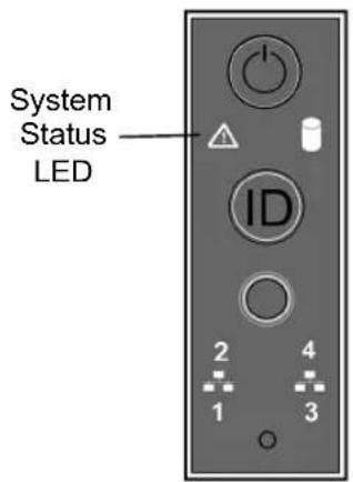
The following table provides a description of each LED state.
Table 1-5 System Status LED states
| DescriptionCriticalityStateColor | |||
| No color | system is not operating. | Not readyOff - The System power is off (AC and/or DC)■ System is in EuP Lot6 Off Mode■ System is in S5 Soft-Off State | |
| HealthySolid on (S0) Green that the system is running (in S0 State) and its status is “Healthy”. The system is not exhibiting any errors. AC power is present and BMC has booted and manageability functionality is up and running. | |||
| ~1 Hz blinkGr~1 Hz blinkGr | DegradedThe system is operating in a degraded state although still functional.orThe system is operating in a redundant state but with an impending failure warning.Degraded (continued) | System degraded:■ Redundant loss, such as power supply or fan. Applies only if the associated platform sub-system has redundancy capabilities.■ Fan warning or failure when the number of fully operational fans is more than minimum number needed to cool the system.■ Non-critical threshold crossed: Temperature (including HSBP temp), voltage, input power to power supply, output current for main power rail from power supply and Processor Thermal Control (Therm Ctrl) sensors.■ Power supply predictive failure occurred while redundant power supply configuration was present.■ Unable to use all of the installed memory (one or more DIMMs failed/disabled but functional memory remains available).■ Battery failure■ BMC executing in uBoot. (Indicated by Chassis ID blinking at 3Hz). System in degraded state (no manageability). BMC uBoot is running but has not transferred control to the BMC Linux. Server will be in this state 6-8 seconds after BMC reset while it pulls the Linux image into flash.System degraded (continued):■ BMC booting Linux. (Indicated by Chassis ID solid ON). System in degraded state (no manageability). Control has been passed from BMC uBoot to BMC Linux itself. It will be in this state for 10-20 seconds.■ BMC Watchdog has reset the BMC.■ Power unit sensor offset for configuration error is asserted.■ Hard disk drive HSC is off-line or degraded. | |
| ~1 Hz blinkAm | Non-criticalThe system is operating in a degraded state with an impending failure warning.However, the system is still functioning. | Non-fatal, although the system is likely to fail due to the following issues:■ Critical threshold crossed – Voltage, temperature (including HSBP temp), input power to power supply, output current for main power rail from power supply and PROCHOT (Therm Ctrl) sensors.■ VRD Hot asserted■ Minimum number of fans to cool the system not present or failed■ Hard drive fault■ Power Unit Redundancy sensor – Insufficient resources offset (indicates not enough power supplies present)■ Correctable memory error threshold has been reached for a failing DIMM when the system is operating in a non-redundant mode. | |
| Solid onAmber | Critical, non-recoverable- System is halted | Fatal alarm - system has failed or shutdown:CPU CATERR signal assertedMSID mismatch detected (CATERR also asserts for this case)CPU1 is missingCPU Thermal TripNo power - power faultDIMM failure when there is only one DIMM present; no other good DIMM memory presentRuntime memory uncorrectable error in non-redundant mode. | |
| Solid onAmber | Critical, non-recoverable- System is halted | Uncorrectable Runtime memory error in non-redundant modeDIMM Thermal Trip or equivalentCPU ERR2 signal is assertedBMC/Video memory test failed (Chassis ID shows blue/solid-on for this condition)SBB Thermal Trip or equivalent240VA faultBoth uBoot BMC FW images are bad (Chassis ID shows blue/solid-on for this condition)Fatal Error in processor initialization:Processor family not identicalProcessor model not identicalProcessor core/thread counts not identicalProcessor cache size not identicalUnable to synchronize processor frequencyUnable to synchronize QPI link frequency | |
About the Power button LED states
The Power button is located on the Veritas 5250 Appliance control panel. It is used to turn the appliance on and off.
Figure 1-7 Power button control panel location

The following table provides a description of each power state.
Table 1-6 Power button LED states
| DescriptionLEDPower ModeState | |||
| OffNon-ACPIPower | The system power is off, and the BIOS has not initialized the chipset. | ||
| OnNon-ACPIPower | The system power is on and the green Power button LED is active. | ||
| S0 | (Advanced Configuration and Power Interface) | Steady onACPI | The system and the operating system are up and running. |
| S5 | (Advanced Configuration and Power Interface) | OffACPI | Mechanical is off and the operating system has not saved any context to the hard disk drive. |
About the 5250 Appliance rear panel
The rear panel of the appliance has several access ports and other features, which are displayed in the following figures.
Figure 1-8 Veritas 5250 Appliance rear panel overview

Table 1-7 Veritas 5250 Appliance rear panel features and connectors
| FunctionNumber | |
| 1,2 | Power Supply 1 and Power Supply 2 - Dual, redundant, and hot-swappable power supply modules |
| DB-15 VGA monitor connector3 | |
| Serial port - Serial connection for Veritas Technical Support use only4 | |
| Three stacked USB 3.0 Type A serial ports for general use5 | |
| 6 | IPMI port - An external RJ45 port used for appliance remote management purposes |
| 7 | eth0/host0■ NetBackup Appliance (eth0):Used for the initial configuration of the appliance. After completing the initial configuration, you can connect NIC1 (eth0) to an administrative network that does not provide any backup data transfer. For more information, see the NetBackup^TM 52xx Appliance Initial Configuration Guide.Note: Veritas does not support forming a NIC bond using eth0/NIC1 with other eth/NIC ports.■ Flex Appliance (host0):A 1-GbE port copper connector that you can connect to an administrative network to manage the appliance system. It is bonded during initial configuration as a standalone bond mgmt0. |
| 8 | eth1/NIC0■ NetBackup Appliance (eth1):A 1-GbE port for general use.■ Flex Appliance (NIC0):A 1-GbE port for general use. |
| 9 | eth2/NIC1■ NetBackup Appliance (eth2):A 1-GbE port for general use.■ Flex Appliance (NIC1):A 1-GbE port for general use. |
| 10 | eth3/NIC2■ NetBackup Appliance (eth3):A 1-GbE port for general use.■ Flex Appliance (NIC2):A 1-GbE port for general use. |
| PCIe riser assembly 1 *11 | |
| PCIe riser assembly 2 *12 | |
| 13 | PCIe riser assembly 3 *Contains two half height PCIe slots.Note: PCIe riser assembly 2 and riser assembly 3 are riveted together. As a result, riser assembly 2 and riser assembly 3 are removed as one unit. |
* The 5250 Appliance add-in cards are available in multiple configurations. Several configurations include at least one Fibre Channel host bus adapter card for VMware, optimized deduplication over Fibre Channel, or tape library connectivity.
In some configurations the Fibre Channel host bus adapter cards are installed into some of the PCIe slots. If the cards are installed in slots 5 and 6, the configuration supports Fibre Transport Media Server (FTMS) mode. Port 1 of each card is configured by default as Target, while port 2 is configured by default as Initiator. If you want, you can configure port 2 on both cards as Target, and you can configure port 1 on both cards as Initiator.
Note: You should not bond copper 1 Gb Ethernet ports that are installed in the appliance chassis with PCIe-based 10/25 Gb Ethernet Fibre Channel ports.
Veritas appliances may include grounding studs in case your lab environment has such a requirement. The studs are located on the rear panel of the appliance. You can use standard grounding practices to connect grounding wires to the studs.
The serial number is located on a vertical bar on the rear panel of the appliance.
Figure 1-9
Serial number location
natural_image
Interior view of a server rack with visible ports, cables, and a red arrow pointing to a component (no readable text or symbols)The ports on the rear panel are color-coded for easy identification.
Figure 1-10
5250 Appliance rear port color codes

Veritas 5250 Appliance I/O configuration optio
The rear panel of the Veritas 5250 Appliance contains three PCIe riser card assemblies. PCIe riser card assemblies 1 and 2 each support three standard PCIe cards, while PCIe riser card assembly 3 supports two low profile PCIe cards. The slots are labeled 1 to 8. Slots 1, 2, and 3 are located in PCIe riser card assembly 2. Slots 4, 5, and 6 are located in PCIe riser card assembly 1, while slots 7 and 8 are located in PCIe riser card assembly 3.
Figure 1-11 Rear panel riser assembly locations and PCIe slot number assignments
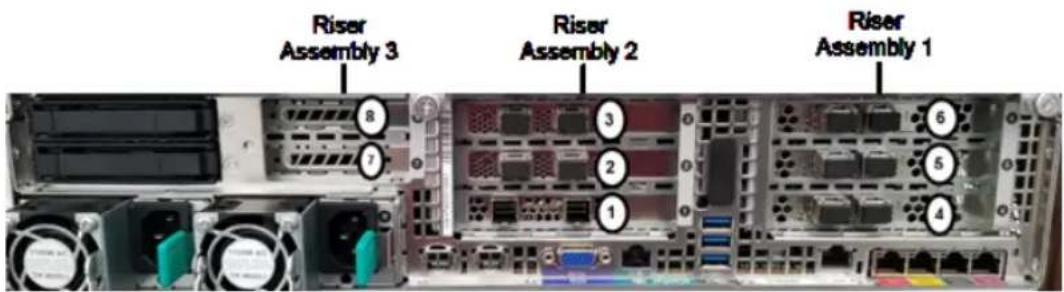
The Veritas 5250 Appliance supports multiple PCIe-based I/O configuration options. The following table shows the different I/O configuration options that are available.
Table 1-8 Available Veritas 5250 Appliance PCIe-based I/O configuration options
| I/O configuration option | Slot 1* | Slot 2 | Slot 3 | Slot 4 | Slot 5 | Slot 6 | Slot 7 | Slot 8 |
| A | - | - | GbE NIC | ----10/25 | ||||
| B | - | - | GbE NIC | --10/25 HBA | --16 Gb FC | |||
| C | - | 10/25 GbE NIC | 10/25 GbE NIC | 16 Gb FC HBA | 16 Gb FC HBA | HBA | --16 Gb FC | |
| D | - | 10/25 GbE NIC | 10/25 GbE NIC | 10/25 GbE NIC | 16 Gb FC HBA | HBA | --16 Gb FC | |
| E | - | 16 Gb FC HBA | 10/25 GbE NIC | 16 Gb FC HBA | 16 Gb FC HBA | HBA | --16 Gb FC | |
| F | - | 10 GbT NIC | 10 GbT NIC | 10 GbT NIC | 16 Gb FC HBA | HBA | --16 Gb FC |
* Slot 1 contains a factory installed PCIe RAID controller
Veritas 5250 Appliance total I/O on-board and PCIe ports
Table 1-9 Total number of Veritas 5250 Appliance on-board and PCIe I/O ports for each I/O configuration
| I/O Configuration option | 1GbT Ethernet ports (copper) | 10/25 Gb Ethernet PCIe ports (optical/SFP) | 16 Gb Fibre10 Channel PCIe ports (optical/SFP) | GbT Ethernet PCIe ports (copper) |
| A | 4 on-board | 2 | 00 | |
| B | 4 on-board | 2 | 02 | |
| C | 4 on-board | 4 | 06 | |
| D | 4 on-board | 6 | 04 | |
| E | 4 on-board | 2 | 08 | |
| F | 4 on-board | 0 | 64 | |
| I/OConfigurationoption | 1GbTEthernetports(copper) | 10/25 GbEthernet PCIeports(optical/SFP) | 16 Gb Fibre Channel PCIeports(optical/SFP) | 10 GbT Ethernet PCIe ports(copper) |
| Cable connection types:copper = Standard copper cableoptical = fiber optic cable | ||||
Available I/O configurations by slot for Veritas 5250 Appliance installations
You can use the supported Veritas 5250 Appliance I/O configurations to best serve the needs of your particular environment.
The controller is installed in both non-shelf and with-shelf configurations
The following table provides information on the make and model of each the PCIe cards that are available for use in each appliance I/O slot.
Table 1-10 Acceptable PCIe-based I/O cards for each appliance I/O slot
| CommentAcceptable PCIe I/O cardSlot | ||
| 1 | INTEL RMS3MD088F 12Gb/s 8 port External PCI-Expressconnect a Veritas 2U12 65.5TiB/72TB3.0 X8 SAS RAID controllerINTEL RMS3MF088F 12Gb/s 8 port External PCI-Expressconnect a Veritas 2U12 65.5TiB/72TB4.0 X8 SAS RAID controller | External RAID controller to which you Storage ShelfExternal RAID controller to which you Storage Shelf |
| 2 | QLE2692 dual-port 16Gb Fibre Channel host bus adapterMellanox ConnectX-4 Lx EN MCX4121A-ACAT Ethernet cardBroadcom P225p Ethernet cardIntel X550-T2 dual-port 10Gb Ethernet card | PCIe-based 16 Gb Fibre Channel host bus adapterPCIe-based 10/25 Gb network interface cardPCIe based 10/25 Gb Ethernet cardPCIe-based 10 Gb dual-port network interface card |
| 3 | Mellanox ConnectX-4 Lx EN MCX4121A-ACAT Ethernet cardBroadcom P225p Ethernet cardIntel X550-T2 dual-port 10Gb Ethernet card | PCIe-based 10/25 Gb network interface cardsPCIe based 10/25 Gb Ethernet cardPCIe-based 10 Gb dual-port network interface card |
| 4 | QLE2692 dual-port 16Gb Fibre Channel host bus adapterMellanox* ConnectX-4 Lx EN MCX4121A-ACAT Ethernet cardBroadcom P225p Ethernet cardIntel X550-T2 dual-port 10Gb Ethernet card | PCIe-based 16Gb Fibre Channel host bus adapterPCIe-based 10/25 Gb network interface cardsPCIe based 10/25 Gb Ethernet cardPCIe-based 10 Gb dual-port network interface card |
| 5 | QLE2692 dual-port 16Gb Fibre Channel host bus adapter | PCIe-based 16Gb Fibre Channel host bus adapter |
| 6 | QLE2692 dual-port 16Gb Fibre Channel host bus adapter | PCIe-based 16Gb Fibre Channel host bus adapter |
QLE2692 dual-port 16Gb Fibre Channel host bus adapter
The QLE2692 dual-port 16Gb Fibre Channel (FC) host bus adapter is used for optimized deduplication over Fibre Channel, tape library connectivity, or Fibre Transport Media Server (FTMS) mode.
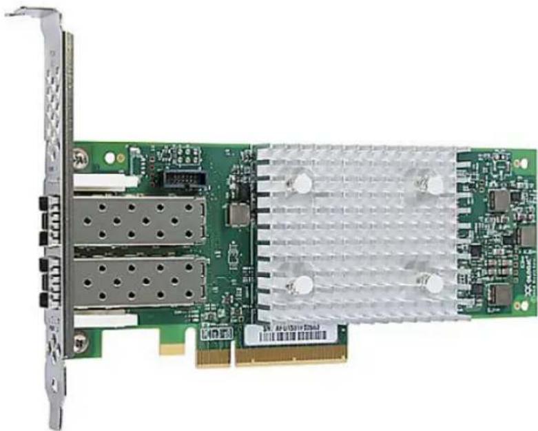
natural_image
Green PCI expansion card with dual ports and a heat sink, no visible text or symbolsTable 1-11 QLE2692 dual-port 16Gb Fibre Channel host bus adapter specifications
| DescriptionItem | |||||
| height | Full HeightBracket | ||||
| Low-profile PCIe card (6.6 inches × 2.731 inches)Form factor | |||||
| consumption (watts) | 9.3 WPower | ||||
| temperature | 0°C to 55°C (32°F to 131°F)Operating | ||||
| temperature | -20°C to 70°C (-4°F to 158°F)Storage | ||||
| humidity | 10% to 90%Operating | ||||
| humidity | 5% to 95%Storage | ||||
| interface type | PCIe v3.0System | ||||
| UL, CSA, TUV, CB, FCC, VCCICertifications | |||||
| cable distances | RateMaximum Cable and Distance (m)(multimode optic cable) | ||||
| OM4OM3OM2OM1 | |||||
| 400380150704Gbps | |||||
| 19015050218Gbps | |||||
| 12510035*16Gbps | |||||
* Not supported
The following table describes the Fibre Channel host bus adapter LED indicator status activity.
Table 1-12 QLE2692 dual-port 16Gb Fibre Channel host bus adapter LED indicator status activity
| Yellow LED | Green LED | Amber LED | Activity |
| Off | Off | Off | Power off |
| On | On | On | Power on (pre-firmware initialization) |
| Blink | Blink | Blink | Power on (post-firmware initialization ) |
| Blink alternately | Blink alternately | Blink alternately | Firmware error |
| Off | Off | On/Blink | 4Gbps link / input-output (I/O) activity |
| Off | On/Blink | Off | 8Gbps link / input-output (I/O) activity |
| On/Blink | Off | Off | 16Gbps link / input-output (I/O) activity |
To purchase a QLE2692 dual-port 16Gb Fibre Channel host bus adapter for your appliance, contact your Veritas sales representative, or your Veritas Partner representative.
QLE2692 dual-port 16Gb Fibre Channel host bus adapter
DescriptionSKU Number
QLOGIC 16Gb Fibre Channel host bus adapter19441
Mellanox ConnectX-4 Lx EN MCX4121A-ACAT Ethernet card
The Mellanox ConnectX-4 Lx EN Ethernet card supports both optical (short wave and long wave optics) and copper (twinax) traffic at 10/25 Gbps Ethernet line rate speeds.
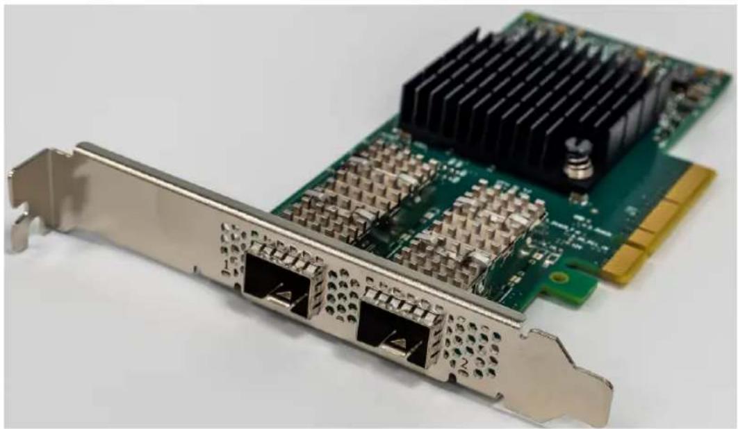
natural_image
Close-up of a green PCI E216 card with multiple Ethernet ports and a black heat sink on top (no text or symbols visible)Note: Veritas recommends that you use Finisar FTLX8574D3BCV SFP part for 10G connectivity and Mellanox MMA2P00-AS SFP part for 25G connectivity.
Table 1-13 Mellanox ConnectX-4 Lx EN MCX4121A-ACAT Ethernet card specifications
| SpecificationItem | |
| Full HeightBracket height | |
| Power consumption | Typical: 9.6 wattsMaximum: 15.0 watts |
| 0°C to 55°C (32 F to 131 F)Operating temperature | |
| -40°C to +70°C (-40°F to +158°F)Storage temperature | |
| 90% RH (operating, non-operating)Storage humidity | |
| PCIe v3.0System interface type | |
| 8.0 GT/s (gigatransfers per second), 8-LaneSpeed and | |
| 10/25Data rate supported per port | |
| 300 LFM (linear feet per minute)Air Flow (minimum) |
Broadcom P225p 10/25Gb PCIe Ethernet card
The Broadcom® BCM957414A4142CC is a dual-port 25 Gb/s, PCI-Express Gen3 x8 Network Interface Card that supports both SFP28/SFP+ optical modules and copper direct attach cable. The card uses the Broadcom BCM57414 25GbE MAC controller with the integrated dual channel 25GbE SFI transceiver.

natural_image
Green PCI network card with internal components and ports, no visible text or symbolsNote: Veritas recommends that you use Finisar FTLX8574D3BCV SFP part for 10G connectivity and Mellanox MMA2P00-AS SFP part for 25G connectivity.
Table 1-14 RS3P4GF016J storage adapter specifications
| SpecificationItem | |
| Full heightBracket height | |
| Power consumption | Typical: 12.5 wattsMaximum: 12.9 watts |
| 0°C to 55°C (32 F to 131 F)Operating temperature | |
| -40°C to +70°C (-49°F to +221°F)Storage temperature | |
| 90% at 35°CStorage humidity | |
| PCIe v3.0System interface type | |
| 8.0 GT/s (gigatransfers per second), 8-LaneSpeed an | |
| 10/25GbData rate supported per port | |
| 150 LFM (linear feet per minute)Air Flow (minimum) |
Intel X550-T2 dual-port 10Gb Ethernet card
The Intel X550-T2 dual-port network interface card connects the appliance to the 10Gb network infrastructure over 10GBase-T technology.

natural_image
Close-up of a green PCI network card with Ethernet ports and internal circuitry (no visible text or symbols)Table 1-15 Intel X550-T2 dual-port 10Gb Ethernet card specifications
| SpecificationItem | |
| Bracket height | Full HeightLow Profile |
| Power consumption | Typical: 11.2 watts @ 10GbpsMaximum 13 watts @ 10Gbps |
| 5°C to 35°COperating temperature | |
| -40 °C to +85 °CStorage temperature | |
| 5% to 95%, non-condensingStorage humidity | |
| PCIe v3.0System interface type | |
| 8.0 GT/s (gigatransfers per second), 4-LaneSpeed an | |
| 10GbE/5GbE/2.5GbE/1GbE/100MbData rate supported | |
| LED indicators | LINK (solid) and ACTIVITY (blinking) LINK SPEED (green=10Gbps; yellow=1Gbps) |
Table 1-15 Intel X550-T2 dual-port 10Gb Ethernet card specifications (continued)
| SpecificationItem | |
| 150 LFM (linear feet per minute)Air Flow |
Intel RAID Adapter RS3P4MF088F
The Intel RAID Adapter RS3P4MF088F is a tri-mode RAID Adapter with 12Gb SAS3 MegaRAID 8 internal ports.

Table 1-16 RS3P4MF088F RAID adapter specifications
| SpecificationItem | |
| Low profile mounting bracketBracket height | |
| Power consumption | Typical: 16.70 wattsMaximum: 17.71 watts |
| 0°C to 55°C (32 F to 131 F)Operating temperature | |
| -45°C to +105°C (-49°F to +221°F)Storage temperatu | |
| Storage humidity | 20-80% RH (operating)05-90% RH (non-operating) |
| PCIe v4.0 (x8 PCI Express* 4.0 PCIe*)System interfa16 GT/s (gigatransfers per second), per laneSpeed a | |
| Data rate supported per port | 12, 6, 3 Gbps per port SAS6, 3 Gbps per port SATA16 Gbps per lane NVMe* |
| 200 LFM (linear feet per minute)Air Flow (minimum) |
Veritas 2U12
65.5TiB/72TB Storage
Shelf
This chapter includes the following topics:
■ Storage Shelf overview
■ Usable appliance storage capacities
■ Components of the S Series Storage Shelf
■ Components of the D Series Storage Shelf
Storage Shelf overview
S Series Storage Shelf
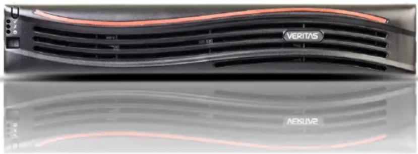
natural_image
Close-up of a Veritas VR headset grille and AEBLVM2 logo (no readable text or symbols beyond branding)The optional Veritas S Series 2U12 65.5TiB/72TB Storage Shelf is a 2U12 drive enclosure that contains twelve 8TB 7200 rpm SAS hard disk drives. Available
storage capacity of the storage shelf is 65 TiB. Each disk drive can be accessed from the storage shelf's front panel. The PCIe RAID controller is used to configure the disk drives into a RAID 6 configuration. One of the disk drives is reserved as a global hot spare and can be used in case of any drive failure.
The S Series Storage Shelf also contains two Storage Bay Bridge 2.1 compliant (SBB) Input/Output (I/O) modules. Each I/O module has three mini-SAS HD ports, which are labeled A, B, and C. As such, each storage shelf contains a total of six mini-SAS HD I/O ports. However, only ports A and B of each I/O module are used to connect the storage shelf to the appliance or other storage shelves.
Each I/O module also includes one Ethernet port and a 3.5mm RS232 Interface-to-Enclosure Services Processor jack. The Ethernet port and the RS232 jack are only used during on-site debugging operations. They are not used during normal appliance operations.
Along with the I/O modules and the disk drives, the Storage Shelf also includes a front control panel. The control panel provides LED indications of the health of the storage shelf. It uses a dual seven segment display for enclosure identification and a switch that is used for storage shelf configuration purposes.
The Storage Shelf serial number appears on a plastic panel on the left side of Power Cooling Module 0 (PCM 0). The storage shelf serial number begins with the letters SH.
See "S Series Storage Shelf front panel components" on page 38.
See "S Series Storage Shelf rear components" on page 42.
See "S Series Storage Shelf control panel" on page 40.
D Series Storage Shelf
The Veritas D Series 2U12 65.5TiB/72TB Storage Shelf is a direct-attach storage enclosures designed to maximize your server storage capacity. Available storage capacity of the storage shelf is 65 TiB. It offers the flexibility of 3.5-inch or 2.5-inch hard drives (with specially designed carriers) in a 2U, 12-drive enclosure. The PCIe RAID controller is used to configure the disk drives into a RAID 6 configuration. One of the disk drives is reserved as a global hot spare and can be used in case of any drive failure.
The D Series Storage Shelf also contains two Storage Bay Bridge 2.1 compliant (SBB) Input/Output (I/O) modules. Each I/O module has four mini-SAS HD ports, which are labeled 1, 2, 3 and 4. As such, each storage shelf contains a total of six mini-SAS HD I/O ports. However, only ports 1 and 2 of each I/O module are used to connect the storage shelf to the appliance or other storage shelves.
The Storage Shelf service tag number is located on a black tab on the right side of the rear panel, between the bottom I/O module and the power supply. Pull out the
tab to display the serial number. The service tag number/serial number is also located on the front panel right side ear. The service tag number/serial number is listed after the "ST:" notation.
See "D Series Storage Shelf front panel components" on page 51.
See "D Series Storage Shelf rear components" on page 54.
See "D Series Storage Shelf control panel" on page 53.
Usable appliance storage capacities
Table 2-1 Usable storage capacities - Veritas 5250 Appliance and Veritas 2U12 65.5TiB/72TB Storage Shelves
| Appliance only | Storage shelf capacity | Appliance and one storage shelf | Appliance and two storage shelves | Appliance and three storage shelves | Appliance and four storage shelves | Appliance and five storage shelves | Appliance and six storage shelves |
| 10TB(9.1TiB) | 72TB(65.5TiB) | 82TB(74.6 TiB) | 154TB(140.1 TiB) | 226TB(205.6 TiB) | 298TB(271.1TiB) | 370TB(336.6TiB) | 442TB(402.1TiB) |
| 40TB*(36.4TiB) | 72TB(65.5TiB) | 112TB(101.9TiB) | 184TB(167.4TiB) | 256TB(232.9TiB) | 328TB(292.4TiB) | 400TB363.9TiB) | 472TB(429.4TiB) |
Note: Usable storage capacities are rounded values. Veritas calculates these values from the raw storage capacities of the various Veritas 5250 Appliance-only configurations. The raw capacity of the Veritas 2U12 65.5TiB/72TB Storage Shelf is 65.5 tebibyte. To determine the exact usable capacities of each configuration, use the following formulas:
* You can add up to six Storage Shelves to an existing Veritas 5250 Appliance with internal storage capacities of 9.1TiB or 36.4TiB. However, before you place the system into a production environment, you must migrate all MSDP data from the appliance to the first external storage shelf. After you migrate the MSDP data, the system's usable storage space may fluctuate, depending on how much actual storage space the MSDP data pool uses.
A 256GB memory upgrade kit is available for purchase when adding the first 2U12 65.5TiB/72TB Storage Shelf, which replaces all existing DIMM modules in the appliance. Contact your Veritas account representative for details.
Note: Spanning MSDP data across both Veritas 5250 Appliance internal storage and a storage shelf is not recommended as it may result in degraded performance.
Warning: Failure to migrate MSDP data after you connect a storage shelf may result in degraded appliance throughput performance.
For more information about migrating MSDP data, see the following document: Moving the MSDP partition from a base disk to an expansion disk for optimum performance.
Components of the S Series Storage Shelf
The following sections describe the components of the Veritas S Series 2U12 65.5TiB/72TB Storage Shelf.
S Series Storage Shelf front panel components
Hard disk drive capacities and drive bay slot assignr
The Veritas S Series 2U12 65.5TiB/72TB Storage Shelf contains 12 disk drive storage bays that are populated with 8 TB 7200 rpm SAS hard disk drives. The available backup storage capacity of the storage shelf equals 65 TiB. One of the disk drives is reserved as a hot spare. All disk drives are accessible from the front panel of the storage shelf after you remove the storage shelf bezel.
The following figure shows the front panel disk drive slot assignments within the Veritas 2U12 65.5TiB/72TB Storage Shelf.
Figure 2-1 Veritas S Series2U12 65.5TiB/72TB Storage Shelf disk drive slot layout

Hard disk drive carrier characteristics
Each storage shelf hard drive is housed in a disk drive carrier. Each disk drive carrier uses a locking mechanism that secures the disk drive within the storage shelf.
Figure 2-2

The following table describes the disk drive carrier LEDs. Note that the combination of both LEDs provides the status.
Table 2-2 Veritas S Series 2U12 65.5TiB/72TB Storage Shelf disk drive carrier LED status
| Fault (amber) LEDActivity (gre | ||
| OFFOFFNo disk drive installed. | ||
| Drives are installed, turned on, and operational. | during startup. | OFFBlinks during I/O activity and |
| (SES) Device identity set. | ONSCSI Enclosure Services | Blinks at a rate of 1 second ON and 1 second OFF. |
| ONOFFDrive slot fault. | ||
| circuit fault. | ONONDrive fault. Power control | |
| failed. | ONLogical fault. Possible drive | Blinks at a rate of 3 seconds ON and one 1 second OFF. |
Note: For security purposes, each drive tray is locked by default when the storage shelf is shipped from the factory. To access a hard disk drive, each storage bay must be unlocked using a T10 torx screw driver.

natural_image
Close-up of a black screwdriver with a metallic tip, isolated on white background (no text or symbols visible)S Series Storage Shelf control panel
The Veritas S Series 2U12 65.5TiB/72TB Storage Shelf control panel is installed on the front left side of the storage shelf.
Figure 2-3 Veritas S Series 2U12 65.5TiB/72TB Storage Shelf control panel

Table 2-3 Veritas S Series 2U12 65.5TiB/72TB Storage Shelf control panel functions
| DescriptionItemNumber | ||
| Input switch1 | The Input switch enables you to set the Unit Identification display. | |
| 2 | Power On / Standby LED (Green or Amber) | The Power On/Standby LED shows Amber when only standby power is available. Otherwise, the LED shows Green when system power is available. |
| 3 | Module Fault LED (Power Cooling Module, Cooling, I/O module status) (Amber) | The Module Fault LED illuminates when there is a system hardware fault. The system hardware fault may be associated with a fault LED on a Power Cooling Module (PCM) or on an I/O module. |
| Logical status LED (amber) | The Logical Status LED shows a change of status or a fault. Typically these changes of status or faults are associated with the shelf's disk drives. However, the Logical Status LED can also indicate an issue with an internal RAID controller or external RAID controller, or with a host bus adapter. | |
| Unit Identification Display5 | The Unit Identification Display is a dual digit display that provides information about the storage shelf. Its primary function is to assist in the configuration of multiple storage shelves. |
Table 2-4 S Series Control panel LED conditions and statuses
| System Power(Green or Amber) | Module Fault(Amber) | Logical Fault(Amber) | LEDs/Alarms | StatusAssociated |
| NoneOffOffOn (AStured) by power present,Overall Power failed or switched off | ||||
| On (Green) | AOn (A Single beep, then double beep) | Control Panel Power on - test state(Test state = 5 seconds) | ||
| On (Green) | Off | Off | None | Power On - All functions good |
Table 2-4 S Series Control panel LED conditions and statuses (continued)
| System Power(Green or Amber) | Module Fault(Amber) | Logical Fault(Amber) | LEDs/Alarms | StatusAssociated |
| N/AOn (Power) | (Green Module Fault LEDsFan Fault LEDs) | Any Power Cooling Module Fault, Fan Fault, or an over or under temperature issue | ||
| N/AOn (Amber) | (Green LEDs) | Any I/O module fault/I/O module | ||
| Enclosure Logical FaultNoneN/AOn (Am | ||||
| N/AFlashing | (Moole/Gaent)LED on an I/O module | Unknown I/O module type installed(Invalid or Mixed) | ||
| N/AFlashing | (Roer/Gaening)Module Fault LEDsFan Fault LEDs | Unknown Power Cooling Module installed.(Invalid or Mixed) | ||
| OnN/AOn | (Areen) a failed or degraded state | Drive failure has occurred causing loss of availability or redundancy | ||
| FlashingN/AOn | Array Greenan impacted state | Array operating background function | ||
| SES state S1N | FFlaking ID setting different from "start of day" setting |
N/A - Not Applicable
For more information, see the Veritas 5250 Appliance Hardware Installation Guid
S Series Storage Shelf rear components
This section describes the rear panel features of the Veritas S Series 2U12 65.5TiB/72TB Storage Shelf.
The following figure provides an overview of the components that comprise the Veritas S Series 2U12 65.5TiB/72TB Storage Shelf rear panel.
Figure 2-4 Veritas S Series 2U12 65.5TiB/72TB Storage Shelf rear components
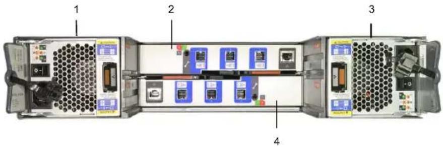
Table 2-5 Veritas S Series 2U12 65.5TiB/72TB Storage Shelf rear components
| ComponentNumber | |
| Power Cooling Module 0 (PCM0)1 | |
| I/O module 02 | |
| Power Cooling Module 1 (PCM1)3 | |
| I/O module 14 |
See "S Series Storage Shelf I/O modules" on page 43.
See "S Series Storage Shelf Power Cooling Modules" on page 47.
See "S Series Power Cooling Module LEDs" on page 49.
S Series Storage Shelf I/O modules
This section discusses the Veritas S Series 2U12 65.5TiB/72TB Storage Shelf I/O modules.
Figure 2-5 Veritas S Series 2U12 65.5TiB/72TB Storage Shelf I/O module

natural_image
Front view of a network switch device with four labeled ports (A, B, C, D) and a USB port, showing internal wiring and external hardware (no readable text or symbols)The following figure and table provides details of the two Veritas 2U12 65.5TiB/72TB Storage Shelf I/O module canisters.
Figure 2-6 Veritas S Series 2U12 65.5TiB/72TB Storage Shelf I/O modules

Table 2-6 Veritas S Series 2U12 65.5TiB/72TB Storage Shelf I/O module components
| DescriptionNumber | |
| I/O module 01 | |
| I/O module 12 | |
| 3 | I/O module Status LEDsSee “S Series I/O module Status LED location and conditions” on page 45. |
| mini-SAS HD ports - A, B, and C4 | |
| Ethernet port (debugging purposes only)5 | |
| RS232 jack (debugging purposes only)6 | |
| 7 | SAS Activity LEDsSee “S Series I/O module SAS Activity LED location and conditions” on page 46. |
S Series I/O module Status LED location and conditions
This section discusses the location of the Status LEDs on the I/O module and the Status LED conditions.
Figure 2-7 S Series I/O module Status indicator LED location
I/O module Status LED location

Table 2-7 S Series I/O module Status LED conditions
| Condition | LED (green) | Fault LED (amber)Activity |
| (amber) | The I/O module has encountered a fault condition.OnModule Fa | |
| The I/O module is operating normally.Off | ||
| The I/O module is on.OnPower (green) | ||
| The I/O module is off.Off | ||
| The I/O module controller is being identified.OnID (blue) |
See "S Series I/O module SAS Activity LED location and conditions" on page 46.
See "S Series Storage Shelf I/O modules" on page 43.
S Series I/O module SAS Activity LED location and conditions
This section discusses the location of the SAS Activity LEDs on the I/O module and the SAS Activity LED conditions.
Figure 2-8 S Series I/O module SAS Activity LED location
SAS Activity LED location
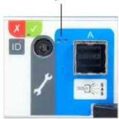
Table 2-8 S Series I/O module SAS Activity LED conditions
| Fault LED (amber)Activity | ||
| OffOffNo Cable Present | ||
| All links up, no activity. | OffOnCable Present | |
| Cable PresentAll links up. | port activity | OffFlash with aggregate |
LED (gr
Table 2-8 S Series I/O module SAS Activity LED conditions (continued)
| Fault LED (amber)Activity | ||
| Any fault which causes operation of the cable to cease or fail to start.For example, an OVERCURRENT trip. | OnOffCritical Fault | |
| Non-Critical FaultAny fault which does not cause the connection to cease operation.For example, not all links established;OVERTEMPERATURE condition detected. | Flash with aggregate port activity | Flashing - One second on; one second off |
See "S Series Storage Shelf I/O modules" on page 43.
See "S Series I/O module Status LED location and conditions" on page 45.
S Series Storage Shelf Power Cooling Modules
The Veritas S Series 2U12 65.5TiB/72TB Storage Shelf includes two Power Cooling Modules (PCM). The dual PCMs provide redundant power to the storage shelf. If one PCM fails, the storage shelf continues to operate as the second PCM continues to supply the storage shelf with power.
Figure 2-9 S Series Power Cooling Module

Table 2-9 S Series Power Cooling Module components
| ComponentNumber | |
| 1 | Power Cooling Module LEDsSee “S Series Power Cooling Module LEDs” on page 49. |
| On/Off switch2 | |
| Release tab3 | |
| AC power socket4 | |
| 5 | Serial number - located on the Power Cooling Module 0 tabNote: The storage shelf serial number begins with the letters SH. |
S Series Power Cooling Module LEDs
The S Series Power Cooling Modules (PCM) use four LEDs to indicate the status of the PCM.
Figure 2-10 S Series Power Cooling Module LEDs
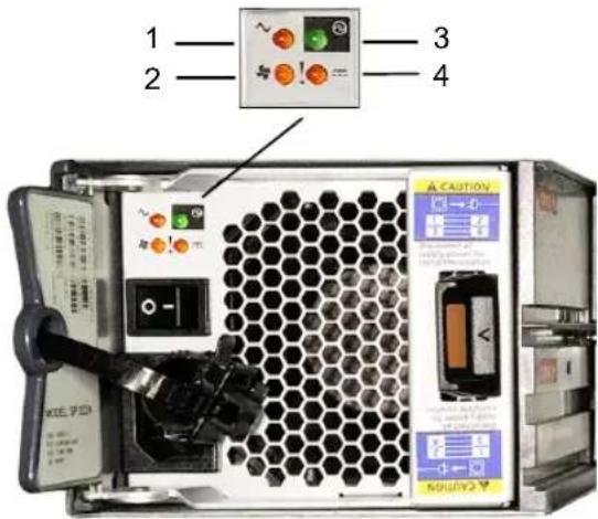
Table 2-10 S Series Power Cooling Module LED legend
| LED conditionNumber | |
| AC fail1 | |
| Fan fail2 | |
| Power Cooling Module OK3 | |
| DC fail4 |
Table 2-11 S Series Power Cooling Module LED conditions
| Status | Power Cooling Module OK (Green) | Fan Fail (Amber) | AC Fail (Amber) | DC Fail (Amber) |
| Cooling Module) | OffOffOffOffNo AC Pc | |||
| Cooling Module only) | OnOnOffOffNo AC Pc | |||
| Cooling Module On OK) | OffOffOffOnAC Preser | |||
| out of tolerance | OnOffOffOnPower Co | |||
| fail | OffOffOnOffPower Co | |||
| Fault (Over temp, over volts, over current) | OnOnOnOffPower Co | |||
| OffOffOffFlashingStanc | ||||
| firmware download | FlashingFlayFayingModu | |||
See "S Series Storage Shelf Power Cooling Modules" on page 47.
Components of the D Series Storage Shelf
The following sections describe the components of the Veritas D Series 2U12 65.5TiB/72TB Storage Shelf.
D Series Storage Shelf front panel components
Hard disk drive capacities and drive bay slot assignr
The Veritas D Series 2U12 65.5TiB/72TB Storage Shelf contains 12, 3.5-inch SAS hot-swappable hard disk drives. The available backup storage capacity of the storage shelf equals 65 TiB. One of the disk drives is reserved as a hot spare. All disk drives are accessible from the front panel of the storage shelf after you remove the storage shelf bezel.
The following figure shows the front panel disk drive slot assignments within the Veritas D Series 2U12 65.5TiB/72TB Storage Shelf.

Hard disk drive indicator patterns
Figure 2-11
Hard disk drive indicators

hard disk drive activity indicator (green)1
hard disk drive status indicator (green and amber)2
hard disk drive3
The following table describes the disk drive carrier status indicator pattern.
Table 2-12 Disk drive carrier status indicator pattern
| ConditionStatus indicator pattern (RAID C) | |
| Blinks green two times per second | Identify hard disk drive or preparing for removal |
| Hard disk drive ready for insertion or removalOff | |
| Hard disk drive predicted failureBlinks green, amber, | |
| Hard disk drive failedBlinks amber four times per sec | |
| Hard disk drive rebuildingBlinks green slowly | |
| Hard disk drive onlineSteady green | |
| three seconds, and turns off in six seconds. | Rebuild abortedBlinks green for three seconds, ambe |
Note: The hard disk drive status indicator remains off until all hard disk drives are initialized after system power is turned on. Hard disk drives are not ready for insertion or removal during this time.
D Series Storage Shelf control panel
The Veritas D Series 2U12 65.5TiB/72TB Storage Shelf control panel is installed on the front left side of the storage shelf.
Figure 2-12 Veritas D Series 2U12 65.5TiB/72TB Storage Shelf control panel
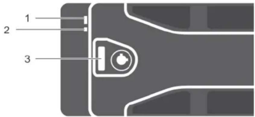
Table 2-13 Veritas D Series 2U12 65.5TiB/72TB Storage Shelf control panel functions
| DescriptionItemNumber | ||
| Enclosure status LED | The enclosure status LED lights when the enclosure power is on. | |
| Power LED2 | The power LED lights when at least one power supply unit (PSU) is supplying power to the enclosure. | |
| Latch3 | The latch is used to remove the bezel from the enclosure. |
Table 2-14 D Series Enclosure status LED conditions and statuses
| DescriptionIndicator | |
| Normal operationSolid blue | |
| Blinks blue | Host server is identifying the enclosure or the system identification button is pressed |
| few seconds and then turns off | EMMs are booting or resetting.Blinks amber or remai |
| The enclosure is in a warning state.Blinks amber for | |
| the enclosure is in the fault state.Solid amber |
D Series Storage Shelf rear components
This section describes the rear panel features of the Veritas D Series 2U12 65.5TiB/72TB Storage Shelf.
The following figure provides an overview of the components that comprise the Veritas D Series 2U12 65.5TiB/72TB Storage Shelf rear panel.
Figure 2-13 Veritas D Series 2U12 65.5TiB/72TB Storage Shelf rear components

Table 2-15 Veritas D Series 2U12 65.5TiB/72TB Storage Shelf rear components
| DescriptionIndicatorNumber | ||
| 1 | Power supply unit or cooling module (PS1) | f600 W power supply.See “D Series Power indicator codes” on page 55. |
| 2 | Primary enclosure management module (EMM 0) | Provides a data path between the enclosure and the host server. |
| Secondary EMM (EMM 1)3 | Provides enclosure management functions for the enclosure. | |
| Information tag4 | A slide-out label panel, which helps to record the Service Tag. | |
| Power switches (2)5 | Controls the power supply output to the enclosure. | |
| 6 | Power supply unit or cooling module (PS 2) | f600 W power supply.See “D Series Power indicator codes” on page 55. |
D Series Power indicator codes
This section discusses the power indicator codes of the Veritas D Series 2U12 65.5TiB/72TB Storage Shelf.
Figure 2-14 Veritas D Series 2U12 65.5TiB/72TB Power indicator codes

Table 2-16 Veritas D Series 2U12 65.5TiB/72TB Power indicator codes
| StateColorLEDNumber | |||
| GreenDC power ON — Normal operation. Power supply is connected to DC power and the power switch is on. The power supply module is supplying DC power to the array.OFF — Indicates any one of the following:■ The power switch is off.■ The power supply module is not connected to power.■ There is a fault condition. | |||
| 2 | module fault | YellowPower supply— Fault detected.OFF — OK.Blinks briefly when power is first turned on to the power supply module. | |
| GreenAC power ON — Power supply module is connected to a source of AC power irrespective of whether or not a power switch is on.OFF — Power supply module is completely disconnected from any source of AC power. | |||
Veritas 5250 Appliance and Veritas 2U12 65.5TiB/72TB Storage Shelf cables
This chapter includes the following topics:
■ Power cables
■ Network cable
■ Multi-Mode fiber optic cable
■ Twinaxial copper cables
■ SAS-3 cable
Power cables
Each of the AC power modules in the Veritas 5250 Appliance and in the optional Storage Shelf accept one AC power cable. One end of the AC power cable is connected to the power supply on the appliance or the storage device. The other end of the cable is connected to an external Power Distribution Unit (PDU) on the rack.
Power cables include a live line, a neutral line, and a grounding line.
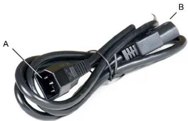
Figure 3-1 AC power cable
natural_image
Close-up of a black electrical power cord with labeled terminals A and B (no additional text or symbols)A AC power connector (IEC-60320-C14) to an external power supply Power Distribution Unit (PDU) on a rack.
AC power connector (IEC-60320-C13) to an appliance or a storage device.B
Note: If your power distribution unit is not compatible with the IEC-60320-C14 plug, then Veritas recommends that you purchase your power cable locally. Make sure the power cable meets or exceeds the indicated power rating.
See "Veritas 5250 Appliance technical specifications" on page 64.
See "Multi-Mode fiber optic cable" on page 59.
See "SAS-3 cable" on page 61.
See "Twinaxial copper cables" on page 60.
See "Network cable" on page 58.
Network cable
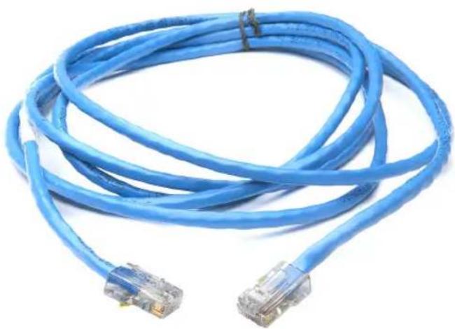
The appliance communicates with the Ethernet networks through an Ethernet network cable. One end of the network cable connects to the management network port or service network port of the appliance. The other end of the cable connects to the network switch or an external gateway. Both ends of the cable are RJ45 connectors.
Figure 3-2 Network cable
natural_image
Blue wired network cable with two connectors (no text or symbols visible)See "Power cables" on page 57.
See "Multi-Mode fiber optic cable" on page 59.
See "SAS-3 cable" on page 61.
See "Twinaxial copper cables" on page 60.
Multi-Mode fiber optic cable
Figure 3-3 Multi-Mode fiber cable

natural_image
Coiled light blue fiber optic cables with white connectors and yellow connectors (no text or symbols visible)Fiber optic cables require Small Form-factor Pluggable (SFP+) transceivers, which are provided with each device having Fibre Channel ports. The diagram shows the SFP, labeled 1, and the fiber optic cable which is attached to it, labeled 2.

Supported SFPs are listed:
■ Finisar
■ JDSU
Note: Veritas recommends that you use Finisar FTLX8574D3BCV SFP part for 10G connectivity and Mellanox MMA2P00-AS SFP part for 25G connectivity.
See "Power cables" on page 57.
See "SAS-3 cable" on page 61.
See "Twinaxial copper cables" on page 60.
See "Network cable" on page 58.
Twinaxial copper cables
The Veritas 5250 Appliance communicates with Ethernet networks through high speed Twinaxial copper cables. If you configure the appliance to communicate with 10/25 Gb Ethernet networks, these cables connect to the 10/25Gb NIC card in the appliance.
These cables are also known as Direct-Access Copper (DAC) cables, and are available in 1-meter, 3-meter, or 5-meter lengths.

natural_image
Coiled black fiber optic cable with two interconnects (no visible text or symbols)See "Power cables" on page 57.
See "Multi-Mode fiber optic cable" on page 59.
See "SAS-3 cable" on page 61.
See "Network cable" on page 58.
SAS-3 cable
SAS-3 data cables are used to connect the optional Veritas 2U12 65.5TiB/72TB Storage Shelf to the Veritas 5250 Appliance. SAS-3 cables have a mini-SAS HD connector on both ends. Two 1m SAS-3 cables are shipped with each S Series Storage Shelf. For the D Series Storage Shelves, a 2 meter cable is standard. Longer SAS-3 cables are supported with the 2U12 Storage Shelf if needed for the configuration.
Figure 3-4 SAS-3 cable

natural_image
Coiled black cable with metallic connectors and blue connectors (no text or symbols visible)See "Power cables" on page 57.
See "Multi-Mode fiber optic cable" on page 59.
See "Twinaxial copper cables" on page 60.
See "Network cable" on page 58.
Technical specifications, Environmental/Protocol standards, and Compliance standards
This appendix includes the following topics:
■ Veritas 5250 Appliance technical specifications
■ Veritas S Series 2U12 65.5TiB/72TB Storage Shelf technical specifications
■ Veritas D Series 2U12 65.5TiB/72TB Storage Shelf technical specifications
■ Environmental specifications
■ Protocol standards
■ Regulatory, compliance, and certification information
■ Product regulatory compliance
■ Country approvals
■ Product safety compliance
■ Product EMC Compliance - Class A Compliance
■ Product environmental compliance
Veritas 5250 Appliance technical specifications
The following table provides technical specifications for the Veritas 5250 Appliance.
Table A-1 Veritas 5250 Appliance technical specifications
| Veritas 5250 ApplianceTechnical Specification | |
| Rack information | 19" EIA standardThe rack rails that are provided for the Veritas 5250Appliance are extensible to 32" (813mm). This distance isthe maximum depth that is allowed between rack posts. Ifthe distance between rack posts is longer than 32" (813mm)the rails and the appliance cannot be properly installed. |
| Two (2) Intel® Xeon® Silver 4214 2.2GHz ProcessorProcessor | |
| 2.20GHzCPU speed | |
| 24 (12 per processor)Cores | |
| System memory (currently supported) | 64 GB256 GB512GBNote: When you purchase the first expansion storageshelf, the Storage Expansion Kit that comes with the storageshelf includes 256 GB of memory that replaces the existing64GB. Additional 256GB memory kit is required when youadd the fifth shelf. |
| Memory type and configuration(DIMMs) | DDR4 RDIMM8 x 8GB (64GB)8 x 32GB (256GB)16 x 32GB (512GB) |
| SAS RAID card installed in PCIe riser assembly (Y/N) | Mezzanine card: YesPCIe RAID card: Yes |
| 4 GB is also included on the external PCIe RAID controllerRAID | |
| Usable MSDP and AdvancedDisk storage capacity(TiB) | Appliance: 9.1TiB, 36.4TiBEach storage shelf: 65.5TiBMaximum configuration shipped from the factory: 429.4TiB |
| shelves | 6Maximum number of storage |
| Up to 4 maximum1 Gb Ethernet ports | |
| Up to 6 maximum10/25 Gb Ethernet ports | |
| Up to 8 maximum16 Gb Fibre Channel ports | |
| Dimensions (IEC rack compliant) | Height: 8.89cm (3.5") (approximately 2U)Width: 48.26cm (19")Depth: 79.38cm (31.25") |
| 23.26 kg (51.28 lbs)Maximum weight | |
| AC power requirements | 110 VAC at 6.2 A220 VAC at 3.2 A |
| AC power cable | Specification: IEC-60320-C14 to IEC-60320-C13, 10A/250V, Black, 4 ftThe IEC-60320-C14 plugs into a Power Distribution Unit.The IEC-60320-C13 plugs into an appliance or storage shelf power supply.Note: If your power distribution unit is not compatible with the IEC-60320-C14 plug, then Veritas recommends that you purchase your power cable locally. Make sure the power cable meets or exceed the indicated power rating.See “Power cables” on page 57. |
| 50/60HzAC Frequency range | |
| 240 wattsTypical power consumption | |
| with a maximum of six connected external storage shelves | 1776 watts (3.76 watts per TB)Typical power consumption |
| 550 wattsMaximum power consumption | |
| with a maximum of six connected external storage shelves | 3430 watts (7.27 watts per TB)Maximum power consumption |
| System cooling requirement (heat dissipation) | 819 BTU/hr (Typical)1876.7 BTU/hr (Maximum) |
| System cooling requirement with maximum external storage (heat dissipation) | 6060 BTU/hr (Typical)11703.6 BTU/hr (Maximum) |
| Operating voltage | 100V - 127 VAC200V - 240 VAC |
| 90% +Power conversion efficiency | |
| 70 dBAAcoustic noise |
See "Veritas S Series 2U12 65.5TiB/72TB Storage Shelf technical specifications" on page 66.
Veritas S Series 2U12 65.5TiB/72TB Storage technical specifications
The following table provides technical specifications for a Veritas S Series 2U1265.5TiB/72TB Storage Shelf.
Table A-2 Veritas S Series 2U12 65.5TiB/72TB Storage Shelf technical specifications
| DescriptionTechnical specification | |
| Rack information | The rack installation height is the space occupied by a storage shelf in a rack cabinet. The height for the storage shelf is 3.5 inches, 88.9mm. The shelf fits into a 2U rack space. Install the storage shelf in a rack cabinet that is 19 inches (483mm) wide.The rack rails that are provided for the storage shelf are extensible to 32" (813mm). This distance is the maximum depth that is allowed between rack posts. If the distance between rack posts is longer than 32" (813mm) the rails and the appliance cannot be properly installed. |
| Hot swappable components | Disk drives, power cooling modules, and I/O modules (Storage Bay Bridge (SBB) 2.1) |
| 65.5TiB/72TBUsable storage capacity (TB) | |
| populated) | 28 kg (62 lbs)Maximum weight (fully |
| 52 kg (115 lbs)Shipping weight | |
| Dimensions | Height: 8.89cm (3.5") (approximately 2U)Width: 48.26cm (19") ICE rack compliantDepth: 60.20cm (23.7") |
| Dual ported 12Gb/s SAS drivesDevice types supported | |
| 12Maximum drives per enclosure | |
| Typical power consumption | 256 watts per storage shelfYou can connect a maximum of six storage shelves to the Veritas 5250 Appliance. |
| Maximum power consumption | 480 watts per storage shelfYou can connect a maximum of six storage shelves to the Veritas 5250 Appliance. |
| System cooling requirement (heat dissipation) | 873 BTU/hr (typical)1637.8 BTU/hr (Maximum) |
| Operating voltage | 100V - 127VAC200V - 240VAC50/60HzAC Frequency range |
| >80% @ 100V, >80% @240V (>30% load)Power conversion efficacy | |
| 63 dBAAcoustic noise | |
| -300 to 12,192 m (-1,000 to 40,000 ft)Non-operational altitude | |
| 2g 11mSec half sineOperational shock | |
| 25g 10mSec half sineNon-operational shock | |
| 0.21g RMS 5-500Hz randomOperational vibration | |
| 1.04g RMS 2-200Hz randomNon-operational vibration | |
| (Non-operational) | 0.3g 2-200Hz sinusoidalRelocation vibration |
See "Veritas 5250 Appliance technical specifications" on page 64.
Veritas D Series 2U12 65.5TiB/72TB Storage technical specifications
The following table provides technical specifications for a Veritas D Series 2U12 65.5TiB/72TB Storage Shelf.
Table A-3 Veritas D Series 2U12 65.5TiB/72TB Storage Shelf technical specifications
| DescriptionTechnical specification | |
| Rack information | The rack installation height is the space occupied by a storage shelf in a rack cabinet. The height for the storage shelf is 3.43 inches, 87mm. The shelf fits into a 2U rack space. Install the storage shelf in a rack cabinet that is 19 inches (483mm) wide.The rack rails that are provided for the storage shelf are extensible to 32" (813mm). This distance is the maximum depth that is allowed between rack posts. If the distance between rack posts is longer than 32" (813mm) the rails and the appliance cannot be properly installed.Disk drives, power cooling modules, and I/O modulesHot swappa |
| 65.5TiB/72TBUsable storage capacity (TB) | |
| populated) | 28.59 kg (63 lbs)Maximum weight (fully |
| Dimensions | Height: 8.7cm (3.43") (approximately 2U)Width: 48.2cm (18.98") ICE rack compliantDepth: 54.61cm (23.3") |
| Dual ported 12Gb/s SAS drivesDevice types supported | |
| 12Maximum drives per enclosure | |
| Typical power consumption | AC - 600WDC - 700WYou can connect a maximum of six storage shelves to the Veritas 5250 Appliance. |
| System cooling requirement (heat dissipation) | AC - 2047BTU/hrDC - 2388BTU/hr. |
| Temperature | Operating: 10° to 35°C (50° to 95°F) with maximum temperature gradation of 10°C per hourStorage: -40° to 65°C (-40° to 149°F) with temperature gradation of 20°C per hour |
| Relative humidity | Operating: 8% to 85% (non-condensing) with maximum humidity gradation of 10% per hourStorage: 5% to 95% (non-condensing) |
| 8.6A at 100V, 4.3A at 240VAmperage | |
| Supported continuous consumption | Up to 1.2A at +5VUp to 0.5A at +12V |
| Operating voltage | 100V - 240V AC48V DC200V - 240VAC50/60HzAC Frequency range |
| -16 to 10,600 m (-50 to 35,000 ft)Non-operational altitude |
Environmental specifications
Veritas Appliance compute node environmental specifications
Table A-4 Veritas Appliance compute node environmental specifications
| Specification | |
| ASHRAE A2 (10°C to 35°C) (50°F to 95°F)Operating temperature | |
| Non-operating temperature | -25°C to 70°C (-14°F to 158°F)The non-operating temperature is defined as the temperature of the system when the system is turned off. It is also referred to as the storage temperature.Veritas recommends that you do not store the system in an environment where the temperatures fall outside of the listed temperature range. |
| (RH) | 20% RH to 80% RHOperating humidity |
| humidity | 8% RH to 90% RHNon-operating |
| (feet) | -30 to 3000 m with ASHRAE A2 class derating (0 to 10,000 ft)Operating temperature gradient |
| (per hour) | 10°C/h (50°F/h)Temperature gradient |
See "Regulatory, compliance, and certification information" on page 71.
Protocol standards
The following table provides standards with which the Veritas 5250 Appliance and the Veritas 2U12 Storage Shelf comply.
Table A-5 Veritas 5250 Appliance / Veritas 2U12 Storage Shelf standards compliance
| VersionStandard | |
| IPMI 2.0 | Intelligent Platform Management Interface Specification Second Generation v2.0, Document Revision 1.0 |
| SMBIOS | System Management BIOS (SMBIOS) Reference Specification, Version 2.5 |
| SAS - 3.0SAS | |
| ACPI | Advanced Configuration and Power Interface Specification, Revision 3.0, September 2 |
| RFC0791: Internet ProtocolIP | |
| INCITS T11 (X3T9.3)FC | |
| PCIe 3.0PCIe Express |
See "Veritas 5250 Appliance technical specifications" on page 64.
See "Veritas S Series 2U12 65.5TiB/72TB Storage Shelf technical specifications" on page 66.
See "Veritas D Series 2U12 65.5TiB/72TB Storage Shelf technical specifications" on page 68.
See "Environmental specifications" on page 70.
Regulatory, compliance, and certification information
The following sections give information about the product regulations and compliance.

WARNING
To ensure regulatory compliance, you must adhere to the assembly instructions in this guide to ensure and maintain compliance with existing product certifications and approvals. Use only the described, regulated components that are specified in this guide. Use of other products or components may void the regulatory approvals of the product. The result is noncompliance with product regulations in the region in which the product is sold.
Alterations to the configuration of your appliance may require additional compliance testing.
This product is an FCC Class A device. Integration of it into a Class B system does not result in a Class B device.
Product regulatory compliance
The NetBackup appliance, when correctly integrated per this guide, complies with the following safety and electromagnetic compatibility (EMC) regulations.
Intended Application - This product was evaluated as Information Technology Equipment (ITE), which may be installed in offices, schools, computer rooms, and similar commercial type locations. The suitability of this product for other product categories and environments, other than an ITE application, may require further evaluation. Other product categories and environments may include medical, industrial, telecommunications, NEBS, residential, alarm systems, and test equipment.
Country approvals
■ US/Canada
■ CE - European Union (EU)
■ Australia / New Zealand
■ KCC South Korea
■ EACU Certification
■ IRAM Certification (Argentina)
Technical specifications, Environmental/Protocol standards, and Compliance standards Product safety compliance
- CCC Certification (China)
BIS India
NOM Mexico
InMetro Brazil
■ NRCS & SABS South Africa
BSMI Taiwan
■ VCCI Japan
KVALITET Serbia
Note: Other countries are either based on these requirements or do not require certification. For more regulatory compliance information please refer to this link: Regulatory Compliance / Homologation
Product safety compliance
The following is a list of product safety compliance norms for different countries:
■ UL60950 - CSA 60950 (USA / Canada)
■ EN62368-1:2014 + AC:2015
■ EU Directive: Low Voltage 2014/35/EU
CSA C22.2 No. 62368-1
EN60950 (EU)
■ FCC /ICES-003 - Emissions (USA/Canada) Verification
■ VCCI Emissions (Japan)
■ AS/NZS 3548 Emissions (Australia / New Zealand)
■ BSMI CNS13438 Emissions (Taiwan)
Note: For a complete list of regulatory notices please refer to this link:
Veritas Safety and Compliance Guide
Product environmental compliance
Use of banned substances are restricted in accordance with world-wide regulatory requirements. Restrictions include quantity limitations on the following:
■ Quantity limit of 0.1% by mass (1000 PPM) for: Lead, Mercury, Cadmium, Hexavalent Chromium, Polybrominated Biphenyls Diphenyl-Ethers (PBB/PBDE), Bis (2-ethylhexyl) phthalate (DEHP), Benzyl butyl phthalate (BBP), Dibutyl phthalate (DBP), Diisobutyl phthalate (DiBP).
■ Quantity limit of 0.01% by mass (100 PPM) for: Cadmium
■ California Code of Regulations, Title 22, Division 4.5, Chapter 33: Best Management Practices for Perchlorate Materials
■ China - Restriction of Hazardous Substances (China RoHS)
■ India RoHS
■ EU WEEE Directive
■ EU Packaging Directive
■ EU Batteries Directive
■ EU Commission Regulation (EU) 2019/424 of 15 March 2019
■ EU REACH Regulation
Product environmental declarations of compliance are available in this link.
Symbols
16Gb Fibre Channel HBA 26
A
about
disk drive LED indicators 12
Appliance
configurations 6
control panel 13
system Status LED indicator 15
disk drive configurations 10
disk drive LEDs 12
features
DIMMs 8
memory configurations 8
processors 8
front panel drive slots 10
front panel USB port 13
overview 6
RAID configuration 10
serial number 10
usable storage capacities 37
appliance
control panel
Power button LED states 18
system status LED location 15
power button LED 19
rear panel
features and connectors 19
appliance configurations
available 23–24
C
cables
multi-mode fiber optic
description 59
network
description 58
power
description 57
cables (continued)
SAS-3
description 61
Twinaxial copper
description 60
components
front panel
Storage Shelf 38
Veritas 2U12 65.5TiB/72TB Storage Shelf 38
Control panel
Appliance
system LED descriptions 13
appliance
power button LED states 18
control panel
Storage Shelf 40
control panel LED descriptions
Storage Shelf 40
D
disk drive configurations
Appliance 10
disk drive LED indicators
Appliance 12
disk drive LEDs
Appliance 12
disk drive slots
Appliance 10
drive bay slot assignments
Storage Shelf 38
E
Environmental specifications 70
F
FC HBA LED status lights
16Gb Fibre channel HBA 26
Fibre Channel card 26
H
hard disk drive capacities
Storage Shelf 38
hardware configurations
available 23–24
|
I/O configuration
ethernet card 29
I/O configurations
available 25
I/O modules
Storage Shelf 43
LED location and conditions 45
L
LED descriptions
appliance
system status 15
LED indicator status
Fibre Channel HBA 28
LED location and conditions
I/O modules
Storage Shelf 45
0
overview
appliance 6
Storage Shelf 35
P
PCIe add-in cards
16Gb Fibre Channel HBA 26
specifications
QLE2692 dual-port 16Gb FC HBA 26
PCIe slot configurations 23–24
power button LED
appliance 19
descriptions 19
Power button LED states
appliance
control panel 18
Power Cooling Modules (PCM)
status LEDs
Storage Shelf 49
Storage Shelf 47
processor
appliance 8
RAID levels 8
protocol standards
Veritas 5250 Appliance / Veritas 2U12 Storage
Shelf 71
R
RAID configuration
Appliance 10
rear components
Storage Shelf 42
Rear panel
appliance
features and connectors 19
S
SAS Activity LED location and conditions
I/O modules
Storage Shelf 46
serial number location
Veritas 2U12 65.5TiB/72TB Storage Shelf 47
serial number locations 10
Status LED indicator
appliance control panel 15
Storage Shelf
control panel 40
front panel 38
hard disk drive 38
I/O modules 43
LED location and conditions 45
SAS Activity LED location and conditions 46
overview 35
power cooling module LEDs 49
Power Cooling Modules (PCM) 47
rear panel 42
system status
appliance
LED descriptions 15
system status LED location
appliance
control panel 15
T
technical specifications
Storage Shelf 68
Veritas5250 Appliance 64
U
usable storage capacities
appliance 37
USB port
Appliance 13
V
Veritas 2U12 65.5TiB/72TB Storage Shelf
components 38

- Veritas™ 5250 Appliance Product Description Guide
- Veritas 5250 Appliance Product Description Guide
- Legal Notice
- Technical Support
- Documentation
- Documentation feedback
- Veritas Services and Operations Readiness Tools (SORT)
- Chapter 1 About the Veritas 5250 Appliance .... 6
- Chapter 2 Veritas 2U12 65.5TiB/72TB Storage Shelf .... 35
- Chapter 3 Veritas 5250 Appliance and Veritas 2U12 65.5TiB/72TB Storage Shelf cables .... 57
- Appendix A Technical specifications, Environmental/Protocol standards, and Compliance standards 63
- Index 75
- About the Veritas 5250 Appliance
- Veritas 5250 Appliance overview
- About Veritas 5250 Appliance configurations
- Features and components of the Veritas 5250 Appliance
- Locating the appliance serial number
- Veritas 5250 Appliance front panel disk drive configurations
- About the disk drive LEDs
- About the Veritas 5250 Appliance front panel port
- About the 5250 Appliance control panel
- About the System Status LED states
- About the Power button LED states
- About the 5250 Appliance rear panel
- Veritas 5250 Appliance I/O configuration optio
- Veritas 5250 Appliance total I/O on-board and PCIe ports
- Available I/O configurations by slot for Veritas 5250 Appliance installations
- QLE2692 dual-port 16Gb Fibre Channel host bus adapter
- Mellanox ConnectX-4 Lx EN MCX4121A-ACAT Ethernet card
- Broadcom P225p 10/25Gb PCIe Ethernet card
- Intel X550-T2 dual-port 10Gb Ethernet card
- Intel RAID Adapter RS3P4MF088F
- Veritas 2U12
- 65.5TiB/72TB Storage
- Shelf
- Storage Shelf overview
- D Series Storage Shelf
- Usable appliance storage capacities
- Components of the S Series Storage Shelf
- S Series Storage Shelf front panel components
- Hard disk drive capacities and drive bay slot assignr
- Hard disk drive carrier characteristics
- S Series Storage Shelf control panel
- S Series Storage Shelf rear components
- S Series Storage Shelf I/O modules
- S Series I/O module Status LED location and conditions
- S Series I/O module SAS Activity LED location and conditions
- S Series Storage Shelf Power Cooling Modules
- S Series Power Cooling Module LEDs
- Components of the D Series Storage Shelf
- D Series Storage Shelf front panel components
- Hard disk drive indicator patterns
- D Series Storage Shelf control panel
- D Series Storage Shelf rear components
- D Series Power indicator codes
- Veritas 5250 Appliance and Veritas 2U12 65.5TiB/72TB Storage Shelf cables
- Power cables
- Network cable
- Multi-Mode fiber optic cable
- Twinaxial copper cables
- SAS-3 cable
- Technical specifications, Environmental/Protocol standards, and Compliance standards
- Veritas 5250 Appliance technical specifications
- Veritas S Series 2U12 65.5TiB/72TB Storage technical specifications
- Veritas D Series 2U12 65.5TiB/72TB Storage technical specifications
- Environmental specifications
- Veritas Appliance compute node environmental specifications
- Protocol standards
- Regulatory, compliance, and certification information
- WARNING
- Product regulatory compliance
- Country approvals
- Product safety compliance
- Product environmental compliance
- Symbols
- A
- C
- D
- E
- F
- H
- |
- L
- 0
- P
- R
- S
- T
- U
- V
Brand : VERITAS
Model : 5250
Category : Server