
42512 - Environmental Thermometer Extech - Free user manual and instructions
Find the device manual for free 42512 Extech in PDF.


| Product Type | Infrared Thermometer |
| Brand | Extech |
| Model | 42512 |
| Temperature Range | -58 to 1832°F (-50 to 1000°C) |
| Accuracy | ±4.5°F (2.5°C) from 28 to 200°F; ±1.0% rdg+2°F from 200 to 400°F; varies by range |
| Emissivity | Adjustable 0.10 to 1.00 |
| Field of View | 30:1 (D:S ratio) |
| Laser | Dual, Class 2, <1mW, 630-670nm |
| IR Spectral Response | 8 to 14 μm |
| Response Time | 150 ms |
| Display | Backlit LCD with function indicators |
| Power Supply | 9V battery |
| Auto Power Off | 7 seconds (with LOCK disabled) |
| Dimensions | 5.7 x 4 x 1.6 in (146 x 104 x 43 mm) |
| Weight | 5.7 oz (163 g) |
| Operating Temperature | 32°F to 122°F (0°C to 50°C) |
| Operating Humidity | 10% to 90% RH |
| Storage Temperature | 14°F to 140°F (-10°C to 60°C) |
| Warranty | 3 years |
| Safety Class | Class II Laser Product |
| Main Functions | Non-contact temperature measurement, dual laser targeting, MAX display, backlight, adjustable emissivity, lock mode, high/low alarms, °F/°C switch |
| Battery Replacement | Replace with 9V battery when low battery icon appears |
| Repair Services | Available from Teledyne FLIR; NIST traceable calibration offered |
Frequently Asked Questions - 42512 Extech
User questions about 42512 Extech
0 question about this device. Answer the ones you know or ask your own.
Ask a new question about this device
Download the instructions for your Environmental Thermometer in PDF format for free! Find your manual 42512 - Extech and take your electronic device back in hand. On this page are published all the documents necessary for the use of your device. 42512 by Extech.
USER MANUAL 42512 Extech
Dual Laser InfraRed (IR) Thermometer
MODEL 42512
Introduction
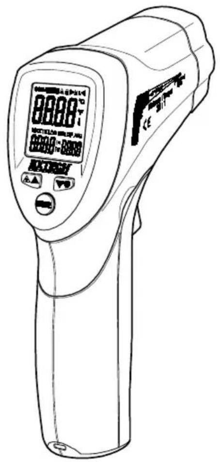
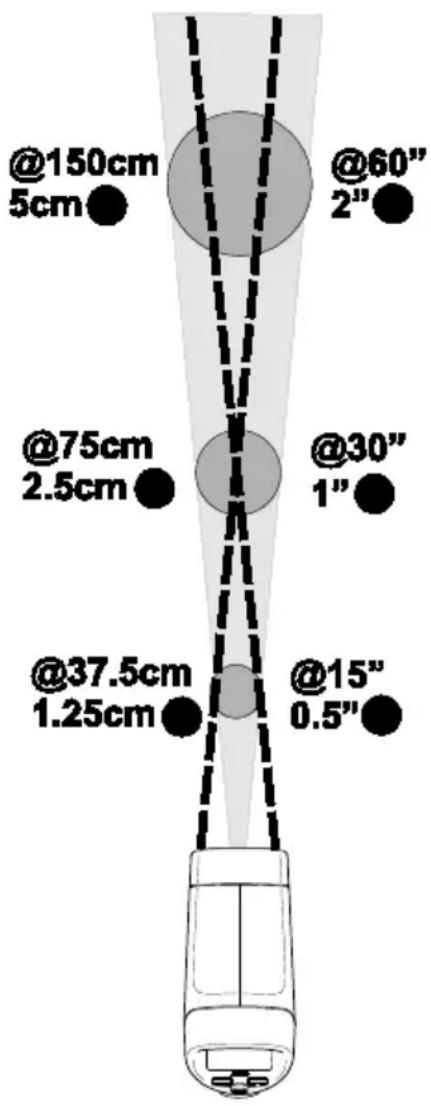
Congratulations on your purchase of the Model 42512 IR Thermometer. This Infrared thermometer measures and displays non-contact temperature readings up to 1832°F (1000°C). At 30 inches, built-in dual lasers converge to a 1 inch target spot to insure accurate targeting and temperature measurement. The adjustable emissivity feature allows the IR thermometer to measure the temperature of virtually any surface. Proper use and care of this meter will provide years of reliable service.
Safety
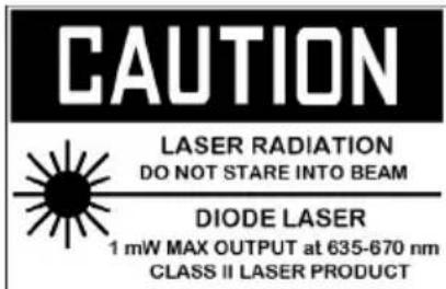
- Use extreme caution when the laser pointer is on
- Do not point the beam toward anyone's eye or allow the beam to strike the eye from a reflective surface
- Do not use the laser near explosive gases or in other potentially explosive areas
Meter Description
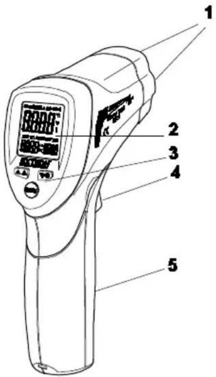
- Dual Laser pointers
- LCD Display
- Function Buttons
- Measurement Trigger
- Battery and F/C Switch compartment
Display Description
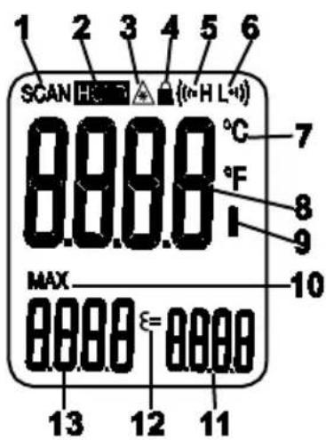
- SCAN, measurement in progress
- HOLD, last measurement locked in display
- Laser pointer active
- Power locked ON
- High limit alarm
- Low limit alarm
- C or F temperature units
- Main temperature display
- Low battery icon
- MAX icon
- Emissivity setting
- Emissivity icon
- Max temperature display
Temperature Measurements
- Hold the meter by its handle and point it toward the surface to be measured.
- Pull and hold the trigger to turn the meter on and begin testing. The temperature reading, MAX temperature reading, the 'SCAN' icon, the emissivity value, and the unit of measure will appear.
- Release the Trigger and the reading will hold for approximately 7 seconds (HOLD will appear on the LCD) after which the meter will automatically shut off. The only exception to this is if the LOCK mode is set to ON.
Note: Select the temperature units (°F/°C) using the switch inside the battery compartment
Dual Laser Pointer
The dual laser pointers are designed to cross at 75 cm. The spot size at this distance is a 2.5 cm diameter and this is the recommended distance to target for most measurements. To turn the lasers on/off:
- Press and release the Trigger
- While HOLD is on the display, press the laser 🔒 button once to turn the lasers on or off.
- The laser icon ⚙ will appear in the LCD when the laser function is enabled.
- The status of the laser will be stored in memory and will remain as the "power-on" condition until changed.
MAX (maximum) temperature display
The highest reading encountered during a single measurement scan is displayed in the MAX display
Backlight
- Press and release the Trigger
- While HOLD is on the display, press the backlight button ⚙ once to turn on the backlight on or off.
- The backlight will illuminate in the LCD when the feature is enabled.
- The status of the backlight will be stored in memory and will remain as the "turn-on" condition until changed.
- Note: The backlight will shorten the battery life. Only use this feature when required.
The MODE button options
The MODE button is used to access the Emissivity, Lock, High alarm, and Low alarm features of the instrument.
- Press and release the Trigger
- While HOLD is on the display, press the MODE button to step through and program the following features. A blinking icon indicates the feature is selected.
= (Emissivity Value)
Press the ▲ or ▼ buttons to change the emissivity value.

(Lock mode On/Off)
Press the ▲ or ▼ buttons to turn the lock feature ON or OFF.

(High Alarm On/Off)
Press the ▲ or ▼ buttons to turn the High Alarm feature ON or OFF.

(High Alarm setting)
Press the ▲ or ▼ buttons to set the high alarm limit value in the main display

(Low Alarm On/Off)
Press the ▲ or ▼ buttons to turn the High Alarm feature ON or OFF.

(Low Alarm setting)
Press the ▲ or ▼ buttons to set the Low alarm limit value in the main display.
High and Low Alarm Feature
The meter has a programmable high and low alarm feature. When either alarm point is reached the meter will alert the user via an audible beep and a blinking LCD display icon. The alarm limit is set, and the feature is enabled/disabled, using the MODE button. The setting is stored and memory and will remain as the “power-on” condition until changed.
Temperature Units
The temperature units can be set to °F or °C using the switch located in the battery compartment.
Lock feature
The LOCK feature disables the Auto Power Off feature for the period of use when selected. The feature is useful for long term temperature monitoring and hands-free use. The meter will revert to auto power off if the trigger is pressed during a locked scan.
Over-range Indication
If the temperature measurement exceeds the specified temperature range, the thermometer will display dashes in place of a temperature reading.
Battery Replacement
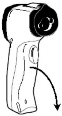
When the low battery symbol 📄 appears on the display, replace the meter's battery (9V). The battery compartment is located behind the panel that surrounds the meter's trigger. Open the compartment by pulling the panel down from the trigger area. Replace the 9V battery and close the battery compartment cover.
natural_image
Line drawing of a handheld device with a circular head and curved arrow indicating motion (no text or symbols)IR Measurement Notes
- The object under test should be larger than the spot (target) size calculated by the field of view diagram (printed on the side of the meter and in this guide).
- Before measuring, be sure to clean surfaces that are covered with frost, oil, grime, etc.
- If an object's surface is highly reflective, apply masking tape or flat black paint to the surface before measuring. Allow time for the paint or tape to adjust to the temperature of the surface it is covering.
- Measurements through transparent surfaces such as glass may not be accurate.
- Steam, dust, smoke, etc. can obscure measurements.
- The meter automatically compensates for deviations in ambient temperature. However, it can take up to 30 minutes for the meter to adjust to extremely wide changes.
- To find a hot spot, aim the meter outside the area of interest then scan across (in an up and down or side to side motion) until the hot spot is located.
Field of View
The meter's field of view is 30:1. For example, if the meter is 30 inches from the target (spot), the diameter of the target must be greater than 1 inch. Other distances are shown in the field of view diagram. Measurements should normally be made as close as possible to the device under test. The meter can measure from moderate distances, but the measurement may be affected by external sources of light. In addition, the spot size may be so large that it encompasses surface areas not intended to be measured.
Emissivity and IR Measurement Theory
IR Thermometers measure the surface temperature of an object. The thermometer's optics sense emitted, reflected, and transmitted energy. The thermometer's electronics translate the information into a temperature reading which is then displayed on the LCD.
The amount of IR energy emitted by an object is proportional to an object's temperature and its ability to emit energy. This ability is known as emissivity and is based upon the material of the object and its surface finish. Emissivity values range from 0.1 for a very reflective object to 1.00 for a flat black finish. For the Model 42512, the emissivity is adjustable from 0.1 to 1.00. Most organic materials and painted or oxidized surfaces have an emissivity factor of 0.95. When in doubt, set the emissivity to 0.95.
Emissivity Factors for Common Materials
| Material under test | Emissivity | Material under test | Emissivity |
| Asphalt | 0.90 to 0.98 | Cloth (black) | 0.98 |
| Concrete | 0.94 | Skin (human) | 0.98 |
| Cement | 0.96 | Leather | 0.75 to 0.80 |
| Sand | 0.90 | Charcoal (powder) | 0.96 |
| Soil | 0.92 to 0.96 | Lacquer | 0.80 to 0.95 |
| Water | 0.92 to 0.96 | Lacquer (matt) | 0.97 |
| Ice | 0.96 to 0.98 | Rubber (black) | 0.94 |
| Snow | 0.83 | Plastic | 0.85 to 0.95 |
| Glass | 0.90 to 0.95 | Timber | 0.90 |
| Ceramic | 0.90 to 0.94 | Paper | 0.70 to 0.94 |
| Marble | 0.94 | Chromium Oxides | 0.81 |
| Plaster | 0.80 to 0.90 | Copper Oxides | 0.78 |
| Mortar | 0.89 to 0.91 | Iron Oxides | 0.78 to 0.82 |
| Brick | 0.93 to 0.96 | Textiles | 0.90 |
| Range | -58 to 1832°F (-50 to 1000°C) | |
| Resolution 0.1 | ° < 1000°, 1° > 1000° | |
| Accuracy | -58°F to -10°F (-50°C to -23°C) | ± 14°F (7°C) Typical |
| -10°F to 28°F (-23°C to -2°C) | ± 8°F (4°C) | |
| 28°F to 200°F (-2°C to 94°C) | ± 4.5°F (2.5°C) | |
| 200°F to 400°F (94°C to 204°C) | ± (1.0%rdg + 2°F [1°C]) | |
| 400°F to 800°F (204°C to 426°C) | ± (1.5%rdg + 2°F [1°C]) | |
| 800°F to 1832°F (426°C to 1000°C) | ± (3%rdg + 2°F [1°C]) | |
| Note: Accuracy is specified for the following ambient temperature range: 73 to 77°F (23 to 25°C) | ||
| Emissivity 0.10 to 1.00 adjustable | ||
| Field of View | D/S = Approx. 30:1 ratio (D = distance; S = spot or target) | |
| Laser pointer | Dual, Class 2 laser < 1mW power; Wavelength is 630 to 670nm | |
| IR Spectral response | 8 to 14 μm (wavelength) | |
| Repeatability | ± 0.5% of reading or ± 1.8°F (1.0°C) whichever is greater | |
General Specifications
| Display | Backlit LCD display with function indicators |
| Response time 150ms | |
| Over range indication “----” | |
| Operating Temperature | 32°F to 122°F (0°C to 50°C) |
| Operating Humidity | 10% to 90%RH operating, <80%RH storage. |
| Storage Temperature | 14 to 140°F (-10 to 60°C) |
| Power Supply | 9V battery |
| Automatic Power Off | 7 seconds, with LOCK disabled |
| Weight | 5.7 oz (163 g) |
| Dimensions | 5.7 x 4 x 1.6 in. (146 x 104 x 43 mm) |
Three-year Warranty
Teledyne FLIR warrants this Extech brand instrument to be free of defects in parts and workmanship for three years from date of shipment (a six-month limited warranty applies to sensors and cables). To view the full warranty text please visit: http://www.extech.com/support/warranties.
Calibration and Repair Services
Teledyne FLIR offers calibration and repair services for the Extech brand products we sell. We offer NIST traceable calibration for most of our products. Contact us for information on calibration and repair availability, refer to the contact information below. Annual calibrations should be performed to verify meter performance and accuracy. Product specifications are subject to change without notice. Please visit our website for the most up-to-date product information: www.extech.com.
Contact Customer Support
Customer Support Telephone List: https://support.flir.com/contact
Calibration, Repair, and Returns: repair@extech.com
Technical Support: https://support.flir.com
Copyright © 2022 Teledyne FLIR Commercial Systems, Inc.
All rights reserved including the right of reproduction in whole or in part in any form
www.extech.com
This document does not contain any export-controlled information

- Dual Laser InfraRed (IR) Thermometer
- Introduction
- Safety
- Meter Description
- Display Description
- Temperature Measurements
- Dual Laser Pointer
- MAX (maximum) temperature display
- Backlight
- The MODE button options
- High and Low Alarm Feature
- Temperature Units
- Lock feature
- Over-range Indication
- Battery Replacement
- IR Measurement Notes
- Field of View
- Emissivity and IR Measurement Theory
- Three-year Warranty
- Calibration and Repair Services
- Contact Customer Support
Brand : Extech
Model : 42512
Category : Environmental Thermometer