
M (Edition 60) - Camera LEICA - Free user manual and instructions
Find the device manual for free M (Edition 60) LEICA in PDF.


| Product Type | Digital view and rangefinder system camera |
| Model | Leica M Edition 60 (Typ 240) |
| Sensor | CMOS, 23.9 x 35.8 mm, 24 MP (5976 x 3992) |
| Lens Mount | Leica M bayonet with 6-bit coding |
| Compatible Lenses | Leica M lenses from 16 to 135 mm |
| Storage Media | SD, SDHC, SDXC cards |
| File Format | DNG (raw), uncompressed |
| Color Space | Adobe RGB |
| ISO Range | 200 to 6400 in 1/3 increments |
| Exposure Modes | Aperture priority (A) and manual |
| Shutter Speeds | A: 32s to 1/4000s; M: 8s to 1/4000s in half steps; B: up to 60s |
| Flash Sync Speed | 1/180s; HSS with compatible units |
| Viewfinder | Brightline frame viewfinder, 0.68x magnification, with rangefinder (split or superimposed image) |
| Effective Rangefinder Basis | 47.1 mm |
| Power Supply | Lithium-ion battery BP-SCL2, 7.4V, 1800 mAh |
| Charger | BC-SCL2, 100-240V AC or 12V DC |
| Dimensions (W x H x D) | Approx. 138.6 x 80 x 42 mm |
| Weight | Approx. 720 g (with battery) |
| Body Material | Stainless steel and light metal alloy, leather covering |
| Tripod Thread | 1/4 inch DIN stainless steel |
| Operating Temperature | 0°C to 40°C (32°F to 104°F) |
| Flash Connection | Accessory shoe with central and control contacts |
| Care Instructions | Clean with soft dry cloth; avoid solvents; protect from dust, moisture, and strong magnetic fields |
| Service Address | Leica Camera AG, Am Leitz-Park 5, D-35578 Wetzlar, Germany |
Frequently Asked Questions - M (Edition 60) LEICA
User questions about M (Edition 60) LEICA
0 question about this device. Answer the ones you know or ask your own.
Ask a new question about this device
Download the instructions for your Camera in PDF format for free! Find your manual M (Edition 60) - LEICA and take your electronic device back in hand. On this page are published all the documents necessary for the use of your device. M (Edition 60) by LEICA.
USER MANUAL M (Edition 60) LEICA
natural_image
Diagram of a mechanical component with a red arrow indicating rotation, no text or symbols present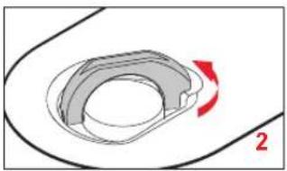
natural_image
Diagram of a mechanical component with a red arrow indicating rotation, labeled '2' (no text or symbols on the diagram itself)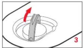
natural_image
Diagram of a mechanical component with a red arrow indicating rotation, no text or symbols present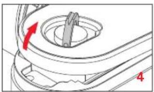
natural_image
Mechanical component diagram showing a rotating knob with red arrow indicating rotation (no text or symbols)Akku einsetzen
natural_image
Diagram of a mechanical device showing a component with a red arrow pointing to it, no text or symbols present.Akku herausnehmen
natural_image
Technical diagram of a mechanical component with a red arrow indicating a specific part (no text or symbols present)natural_image
Diagram showing a device with red arrows indicating rotation or movement, no text or symbols present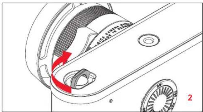
natural_image
Mechanical assembly diagram showing a rotating component with red arrows indicating motion direction (no text or symbols)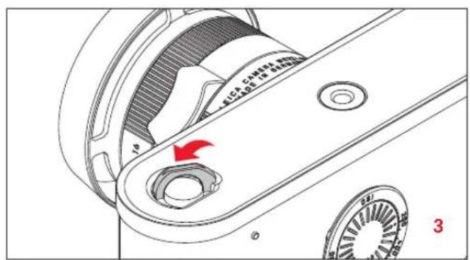
natural_image
Technical line drawing of a mechanical assembly with gears and housing (no text or symbols)LEICA M-OBJEKTIVE
natural_image
Diagram of a camera lens assembly with a magnified inset showing the blade (no text or symbols present)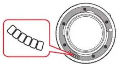
Wichtig:
- Nicht verwendbar:
- Hologon 1:8/15mm,
natural_image
Simple line drawing of a human eye with eyelashes and iris (no text or symbols)unscharf scharf
natural_image
Simple line drawing of an eye with eyebrow and pupil (no text or symbols)Schnittbildmethode
natural_image
Simple geometric diagram with two white rectangles and a black vertical line dividing the right half of a gray rectangle (no text or symbols)unscharf scharf
natural_image
Two white rectangular panels separated by a vertical black line, with gray borders (no text or symbols)BELICHTUNGSMESSUNG
Product Support / Software Support
Am Leitz-Park 5
D-35578 Wetzlar
Telefon: +49(0)6441-2080-111 /-108
Telefax: +49(0)6441-2080-490
info@leica-camera.com / software-support@leica-camera.com
LEICA CUSTOMER CARE
Leica would like to thank you for purchasing the Leica M "Leica 60" edition and congratulate you on your choice. With this unique digital view and rangefinder camera, you have made an excellent choice.
We wish you a great deal of pleasure and success using your new camera. In order to make best use of all the opportunities offered by this high performance camera, we recommend that you first read these instructions.
FCC Note: (U. S. only)
This equipment has been tested and found to comply with the limits for a Class B digital device, pursuant to Part 15 of the FCC Rules. These limits are designed to provide reasonable protection against harmful interference in a residential installation. This equipment generates, uses, and can radiate radio frequency energy and, if not installed and used in accordance with the instructions, may cause harmful interference to radio communications. However, there is no guarantee that interference will not occur in a particular installation. If this equipment does cause harmful interference to radio or television reception, which can be determined by turning the equipment off and on, the user is encouraged to try to correct the interference by one or more of the following measures:
- Reorient or relocate the receiving antenna.
- Increase the separation between the equipment and receiver.
- Connect the equipment into an outlet on a circuitdifferent from that to which the receiver is connected.
- Consult the dealer or an experienced radio/TV technician for help.
FCC Caution:
To assure continued compliance, follow the attached installation instructions and use only shielded inter face cables with ferrite core when connecting to computer or peripheral devices.
Any changes or modifications not expressly approved by the party responsible for compliance could void the user's authority to operate this equipment.
Trade Name: Leica
Model No.: LEICA M EDITION 60 (Typ 240)
Responsible party/
Support contact: Leica Camera Inc.
1 Pearl Count, Unit A
Allendale, New Jersey 07401
Tel.: +1 201 995 0051
Fax: +1 201 995 1684
technicalinfo@leicacamerausa.com
This device complies with Part 15 of the FCC Rules. Operation is subject to the following two conditions:
(1) This device may not cause harmful interference, and (2) this device must accept any interference received, including interference that may cause undesired operation.
LEICA M EDITION 60 (Typ 240)

Tested To Comply
With FCC Standards
FOR HOME OR OFFICE USE
FOR CANADA ONLY:
CAN ICES-3 (B)/NMB-3(B)
CONTENTS
Foreword 66
Warning messages 70
Legal information 70
Disposal of electrical and electronic equipment ....71
Designation of parts 72
Preparations
Using the protector 74
Charging the battery 74
Changing the battery and memory card ....76
Leica M lenses 81
Attaching 83
Removing 83
Controls
Main switch 84
Shutter release 85
Shutter speed setting dial 86
Basic settings
Setting the date and time 88
Setting the ISO sensitivity 89
Fixed camera settings 89
Brightline view and rangefinder 90
Distance metering 91
Exposure metering 92
Turning the exposure meter on/off 92
Exposure modes 93
Aperture priority 93
Exposure lock 94
Manual exposure setting 94
The B setting 95
Values above and below the metering range 95
Flash photography....96
Miscellaneous
Review 100
Transferring data to a computer 100
Working with DNG raw data 100
Adobe® Photoshop® Lightroom® 100
Installing firmware updates 101
System accessories
Replacements
Leica Summilux-M 35mm f/1.4 ASPH.
Precautions and care instructions
General precautions 106
Care instructions ....107
Cleaning the sensor 110
Storage 111
Malfunctions and their resolution ....112
Appendix
Viewfinder displays 114
MTF diagrams 116
Distortion diagrams 117
Vignetting diagrams 117
Index 118
Technical data 120
Leica Service addresses 126
The CE identification of our products documents compliance with the fundamental requirements of the valid EU directives.
WARNING MESSAGES
- Modern electronic components react sensitively to electrostatic discharge. As people can easily pick up charges of tens of thousands of volts, by walking on synthetic carpets for example, a discharge can occur when you touch your camera, particularly if it is placed on a conductive surface. If only the camera housing is affected, this discharge is harmless to the electronics. However, despite built-in safety circuits, the outer contacts, such as the battery or rear panel contacts, should not be touched if at all possible for safety reasons.
- For any cleaning of the contacts, do not use an optical micro-fiber cloth (synthetic); use a cotton or linen cloth instead. Before touching the contacts, you can make sure you discharge any electrostatic charge by deliberately touching a heating or water pipe (conductive, earthed material). You can also avoid soiling and oxidization of the contacts by storing your camera in a dry place with the lens or bayonet cover fitted.
- You should use exclusively the recommended accessories to prevent faults, short circuits or electric shock.
- Do not attempt to remove parts of the housing (covers); specialist repairs can be carried out only at authorized service centers.
LEGAL INFORMATION
- Please ensure that you observe copyright laws. The recording and publication of pre-recorded media such as tapes, CDs, or other published or broadcast material may contravene copyright laws.
• This also applies to all of the software supplied. - The SD and HDMI logos are registered trademarks.
- Other names, company or product names referred to in this manual are trademarks or registered trademarks of the relevant companies.
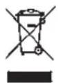
DISPOSAL OF ELECTRICAL AND ELECTRONIC EQUIPMENT
(Applies within the EU, and for other European countries with segregated waste collection systems)
This device contains electrical and/or electronic components and should therefore not be disposed of in general household waste. Instead it should be disposed of at a recycling collection point provided by the local authority. This costs you nothing. If the device itself contains replaceable (rechargeable) batteries, these must be removed first and, if necessary, also be disposed of in line with the relevant regulations. Further information on this issue is available from your local administration, your local waste collection company, or in the store where you purchased this device.
You can find your camera's production date on the stickers in the Guarantee Card and on the packaging. The digits stand for YYYY/MM/DD
DESIGNATION OF PARTS
Illustrations in the front and rear cover pages
Front view
- Lens release button
- Distance meter viewing window
- Brightness sensor ^1
- Viewfinder viewing window
Top view
- Fixed ring with
a. Index for focusing
b. Depth of field scale
c. Red index button for changing lenses
- Aperture setting ring
- External thread
- Thread protection ring
- Index point for aperture setting
- Lens hood
- Focusing ring with
a. Finger grip
-
Main switch with three detent positions for
-
(Camera turned off)
(Camera turned on)
→(Date/time setting, or sensor cleaning) -
Function key
-
Shutter release
-
Time setting dial with detent positions for
-
A for automatic shutter speed control
- Shutter speeds ^1 /4000 - 8s (inc. intermediate values)
- B (long-time exposure)
-Flash sync speed (1/180s)
- Accessory shoe
Rear view
- Viewfinder
- LED for indicating picture mode / recording data
- ISO setting unit with
a. Scale
b. Adjusting dial
c. Index point
Bottom view
(with bottom cover fitted)
- Locking toggle for bottom cover
- Tripod thread A ¼, DIN 4503 (¼")
- Bottom cover
(with bottom cover removed)
- Memory card slot
- Battery compartment
- Battery locking slider
- Bottom cover locking point
PREPARATIONS
USING THE PROTECTOR
If you want to use the camera with a carrying strap, place it in the protector supplied, which is equipped with a permanently attached carrying strap. The protector is attached to the camera using the tripod screw. It has a tripod thread in its metal base.
CHARGING THE BATTERY
The camera is powered by a lithium ion battery.
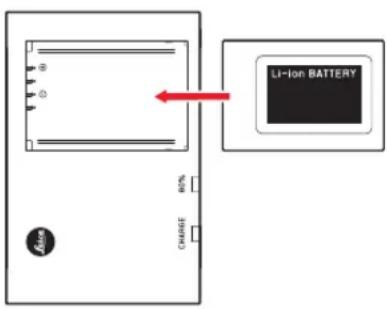
- The green LED marked CHARGE starts flashing to confirm that charging is in progress. As soon as the battery has charged to at least 45 of its capacity, the yellow LED marked 80% also lights up. When the battery is fully charged, the green LED also changes from flashing to continuously lit.
Note:
The 80% LED lights up after around 2 hours due to the charging characteristics.
The charger should be disconnected from the mains when charging is complete. There is therefore no risk of overcharging.
Caution:
- Only the battery type specified and described in this manual (order no. 14 499), or battery types specified and described by Leica Camera AG, may be used in this camera.
- These batteries may only be used in the units for which they are designed and may only be charged exactly as described below.
- Using this battery contrary to the instructions and using non-specified battery types can result in an explosion under certain circumstances.
- The batteries may not be exposed to heat, sunlight, humidity or moisture for long periods. Likewise, the batteries may not be placed in a microwave oven or a high pressure container as this results in a risk of fire or explosion.
- A safety valve in the battery guarantees that any excess pressure caused by improper handling is discharged safely.
- Only the charger specified and described in this manual (order no. 14 494) is to be used. The use of other chargers not approved by Leica Camera AG can cause damage to the batteries and, in extreme cases, can cause serious or life-threatening injuries.
- The charger supplied should be used exclusively for charging this battery type. Do not attempt to use it for other purposes.
- The car charging cable supplied may never be connected while the charger is connected to the mains.
- Ensure that the mains outlet used for charging is freely accessible.
- The battery and charger may not be opened. Repairs may only be carried out by authorized workshops.
Notes:
- The battery should be charged before the camera is used for the first time.
- The battery must have a temperature of 10^ - 30^ / 50^ - 86^ to be charged (otherwise the charger will not turn on, or will turn off again).
- Lithium ion batteries can be charged at any time, regardless of their current charge level. If a battery is only partly discharged when charging starts, it is charged to full capacity faster.
- The batteries warm up during the charging process. This is normal and not a malfunction.
- If the two LEDs on the charger flash rapidly (> 2Hz) after starting charging, this indicates a charging error (e.g. maximum charging time exceeded, voltages or temperatures outside the permitted ranges, or short circuit). In this case, disconnect the charger from the mains and remove the battery. Ensure that the above temperature conditions are met and then restart the charging process. If the problem persists, please contact your dealer, the Leica office in your country or Leica Camera AG.
-
A new battery only reaches its full capacity after it has been fully charged and - by use in the camera - discharged again 2 or 3 times. This discharge procedure should be repeated after approximately every 25 cycles. To ensure a maximum service life of the battery, it should not be exposed to constant extremes of temperature (e.g. in a parked car in the summer or winter).
-
Even when used in optimum conditions, every battery has a limited service life. After several hundred charging cycles, this becomes noticeable as the operating times get significantly shorter.
- The battery should be replaced after a maximum of four years, as its performance deteriorates and reliable operation can no longer be guaranteed, particularly in cold conditions.
- Defective batteries should be disposed of in line with the relevant instructions (see p. 108).
- The replaceable battery provides power to a back-up battery which is permanently fitted in the camera. This back-up battery retains the set date and time for up to 2 months. If this back-up battery becomes discharged it must be recharged by inserting the replaceable main battery. Once the replaceable battery has been inserted, the full capacity of the back-up battery is recovered after about a few days. This process does not require the camera to be turned on.
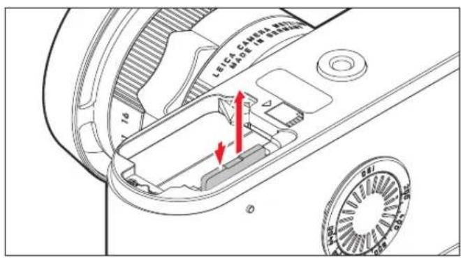
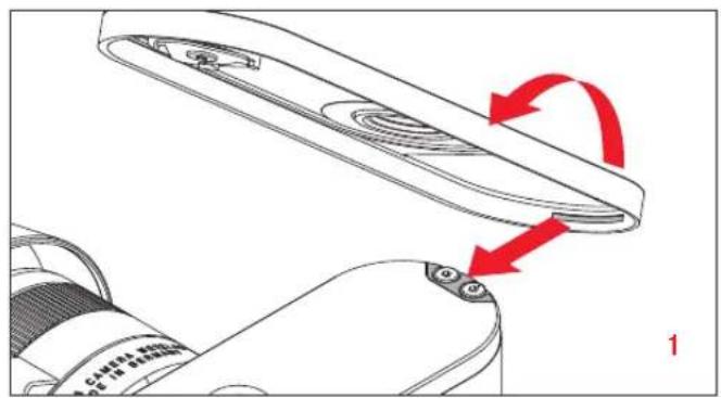
CHANGING THE BATTERY AND MEMORY CARD
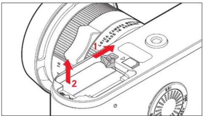
Turn the camera off ⚙(see p. 84).
Important:
Do not open the bottom cover nor remove the memory card or the battery whilst the red LED on the rear of the camera is flashing, indicating picture recording and/or data being saved to the card. Otherwise the unsaved (or not completely saved) picture data may be lost.
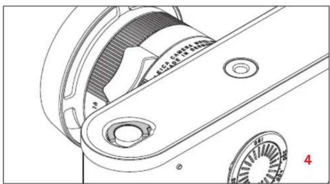
Removing the bottom cover
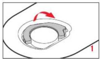
natural_image
Diagram of a mechanical component with a curved ring and directional arrow, no text or symbols present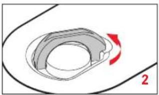
natural_image
Diagram of a mechanical component with a red arrow indicating rotation, labeled '2' (no text or symbols on the diagram itself)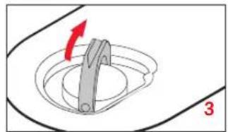
natural_image
Diagram of a mechanical component with a red arrow indicating rotation, no text or symbols present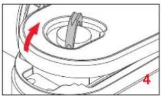
natural_image
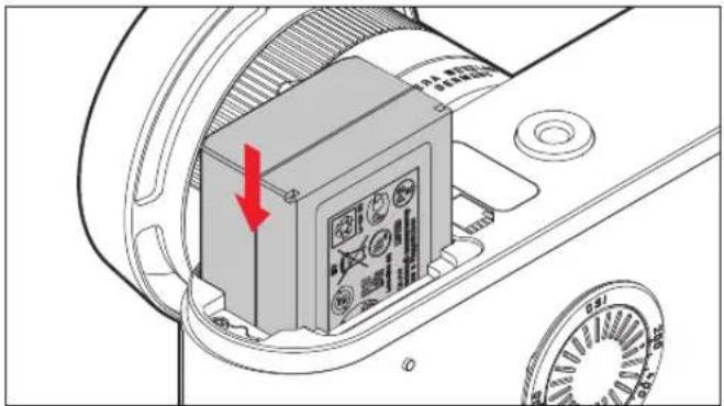
Technical diagram of a mechanical component with a red arrow indicating rotation (no text or symbols)Inserting the battery
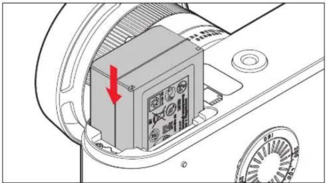
natural_image
Diagram of a device component with a red arrow pointing to a box, showing no text or symbols on the main body.Removing the battery
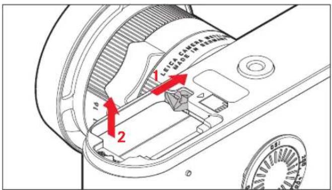
Charge level displays
The current battery capacity can be displayed in the viewfinder:
- Turn on the camera.
If required, i.e. if the camera is turned on but the viewfinder display has been turned off again:
-
Press the shutter release to the first pressure point to activate the viewfi under display.
-
Press the function button once.
The relevant capacity is displayed as a percentage. A dot lights up above it to differentiate it from the memory card capacity display.
Notes:
- The capacity display appears regardless of whether or not the viewfinder display was previously on.
- Remove the battery if you will not be using the camera for a long period of time.
- A maximum of 2 months after the capacity of a battery left in the camera is exhausted (see also the last note under "Charging the battery", p. 74), the date and time need to be re-entered.
Inserting the memory card
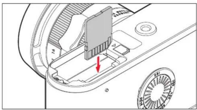
natural_image
Technical diagram of a mechanical component with a red arrow indicating a specific part (no text or symbols present)Removing the memory card
Memory card capacity display
The number of pictures remaining can be displayed in the viewfinder:
- Turn on the camera.
If required, i.e. if the camera is turned on but the viewfinder display has been turned off again:
-
Press the shutter release to the first pressure point to activate the viewfi nder display.
-
Press the function button twice
° The relevant figure is displayed.
The display reverts to its normal status 3s after releasing the function button.
If the card's capacity limit has been reached, Full always appears, regardless of whether the viewfinder display was previously turned on or off.
Compatible memory cards
The camera saves the pictures on an SD (secure digital), SDHC (high capacity), or SDXC (eXtended capacity) card.
SD/SDHC/SDXC memory cards are available from various suppliers and with different capacities and read/write speeds.
Particularly those with high capacities and read/write speeds allow data to be recorded and retrieved very quickly.
The cards have a write protection switch, which can be used to prevent unintentional storage and deletion of pictures. This switch takes the form of a slider on the non-beveled side of the card; in the lower position, marked LOCK, the data on the card is protected.
Notes:
- Do not touch the memory card contacts.
- The range of SD/SDHC/SDXC cards is too large for Leica Camera AG to be able to completely test all available types for compatibility and quality. Although using other card types is not likely to damage the camera or the card, some "no name" cards do not comply with the SD/SDHC/SDXC standards, and Leica Camera AG is unable to provide any guarantee that they will function correctly.
- If the memory card cannot be inserted, check that it is aligned correctly.
- As electromagnetic fields, electrostatic charges, and defects on the camera or the card can lead to damage or loss of the data on the memory card, we recommend that you also transfer the data to a computer and save it there (see p. 100).
- For the same reason, it is recommended that the card is always stored in its antistatic cover.
Close the bottom cover
natural_image
Diagram showing a device with red arrows indicating rotation or movement, no text or symbols present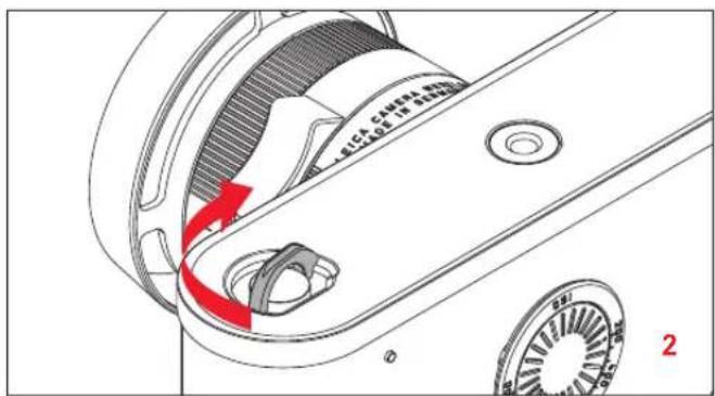
natural_image
Mechanical assembly diagram showing a rotating component with red arrows indicating motion direction (no text or symbols)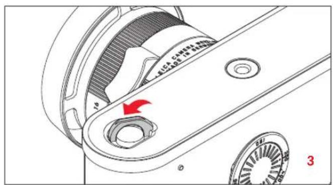
natural_image
Technical line drawing of a mechanical assembly with gears and housing (no text or symbols)LEICA M LENSES
Generally, most Leica M lenses can be used. Details on the small number of exceptions and restrictions can be found in the following notes.
They can be used regardless of the lens features, and whether the lens does or does not have 6-bit coding in the bayonet.
Even without this additional feature, i.e. when using Leica M lenses without identification, the camera will deliver excellent pictures in most situations.
natural_image
Diagram of a camera lens assembly with a magnified inset showing the blade detail (no text or symbols present)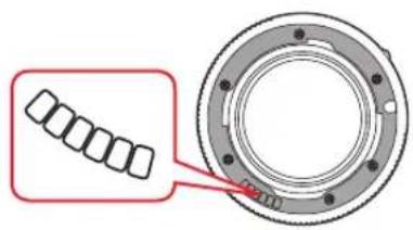
Important:
- Cannot be used:
- Hologon 15mm f/8
- Summicron 50mm f/2 with close up.
- Elmar 90mm f/4 with retractable tube (manufactured from 1954-1968)
- Some versions of the Summilux-M 35mm f/1.4 (not aspherical, manufactured from 1961-1995, Made in Canada) cannot be attached to the camera or will not focus to infinity. The Leica Customer Care department can modify these lenses so that they can be used on the camera.
- Can be used, but risks damaging the camera or lens:
Lenses with retractable tube can only be used with the tube extended, i.e. their tube must never be retracted into the camera. This is not the case with the current Macro-Elmar-M 90mm f/4, as its tube does not protrude into the camera body even when retracted. It can therefore be used without any restrictions.
- Can be used with restrictions
Despite the high precision of the rangefinder on the camera, exact focusing with 135mm lenses with at full stop cannot be guaranteed due to the very low depth of field. Therefore, stopping down by at least 2 stops is recommended.
- Can be used but are excluded from exposure metering
- Super-Angulon-M 21mm f/4
- Super-Angulon-M 21mm f/3.4
- Elmarit-M 28mm f/2.8 with serial nos. before 2 314 921.
Notes:
- The Leica Customer Care department can upgrade many Leica M lenses with 6-bit coding (for address, see p. 126).
- When using the Leica Tri-Elmar-M 16-18-21mm f/4 ASPH., the set focal length is not transferred to the camera and thus is not included in the EXIF data for pictures.
- By contrast, the Leica Tri-Elmar-M 28-35-50mm f/4 ASPH. features mechanical transfer of the set focal length to the camera, necessary to display the appropriate brightline frame in the viewfinder. It is detected by the camera electronics and used for focal length specific compensation. This applies to all three versions of the lens (item numbers 11 625, 11 890, and 11 894).
Attaching the lens
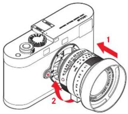
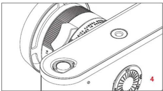
- Turn off the camera
- Hold the lens by the fixed ring.
- Align the red index button on the lens with the release button on the camera body.
- In this position, insert the lens.
- Turn the lens slightly to the right, and you will hear and feel it click into place.
Detaching the lens
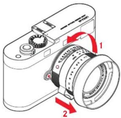
- Turn off the camera
- Hold the lens by the fixed ring.
- Press down the release button on the camera body.
- Turn the lens to the left until its red index button is aligned with the release button.
- Remove the lens.
Notes:
- Generally, to protect the Leica T against ingress of dust etc. into the interior of the camera, it is important always to have a lens or a cover fitted to the camera body.
- For the same reason, when changing lenses work quickly and in an environment that is as dust-free as possible.
- Rear camera or lens covers should not be stored in your trouser pocket as they attract dust that can get into the camera when they are fitted.
CONTROLS
MAIN SWITCH
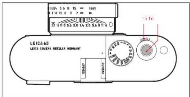
The camera is turned on and off using the main switch. This is located below the shutter release and is a lever with three detent positions:
a. Off
b. Single picture
Pressing the shutter release takes a single picture regardless of how long it is held down for.
c. It is also used to enable the date/time entry and the sensor cleaning function (for more information, see p. 88/110).
Notes:
• After turning on, the camera is ready to use after approx. 1s.
- Even if the main switch is not set to ⚙, the camera is turned off automatically if none of the controls are used for 2 minutes.
- If the camera is out of use for an extended period or is stored in a case, always turn it off at the main switch. This prevents any power consumption, including that which continues to occur in standby mode after the exposure meter is turned off automatically and the display is extinguished. This also prevents pictures from being taken accidentally.
SHUTTER RELEASE
The shutter release has two pressure points:
-
Pressing down to the 1st pressure point
-
activates exposure metering and the viewfinder display
- saves the metered exposure value in aperture priority mode, i.e. the shutter speed determined by the camera (for more details, refer to the "Metering memory lock" section on p. 94)
If the shutter release is held at this pressure point, the display remains on. If the camera was previously in standby mode, it will be reactivated and the displays turned on.
If you let go of the shutter release, the metering system and the displays remain activated for around a further 30s (for more details, refer to the sections under “Exposure metering” starting on p. 92).
Note:
The shutter release button remains blocked
- if the internal buffer memory is (temporarily) full, e.g. after a series of ≥ 16 pictures, or
- if the memory card inserted and the internal buffer memory are (temporarily) full, or
-
if the battery has exceeded its performance limits (capacity, temperature, age)
-
Pressing the shutter release button all the way down takes a picture. The data is then transferred to the memory card.
Note:
To avoid wobble, the shutter release should be pressed gently, not jerkily, until the shutter is released with a soft click.
SHUTTER SPEED SETTING DIAL
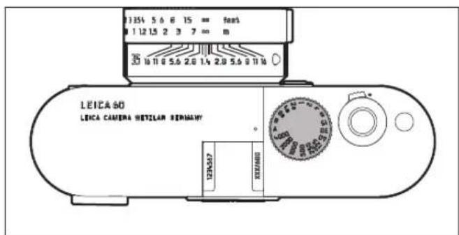
The shutter speed setting dial is used to select the exposure modes.
- Aperture priority mode by selecting the A position (see p. 93),
- Manual mode by selecting a shutter speed of /4000s to 8s (intermediate values in 1/2 step positions are also available),
- The shortest possible sync speed of /180s for flash mode, marked with the symbol (see p. 99), and
- B for long exposures (see p. 96).
The Leica M shutter speed dial has no stop, i.e. it can be turned in either direction from any position. It detents at all marked positions and at the intermediate values. Values between the detent positions cannot be used. More details on setting the correct exposure can be found in the sections under: "Exposure metering" starting on p. 92.
BASIC SETTINGS
SETTING THE DATE AND TIME
Turn the main switch clockwise to i.e. so that and are both invisible.
The actual setting is made using the function button and the viewfinder display.
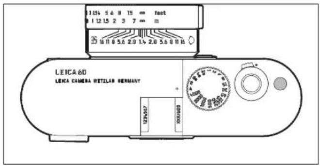
The procedure is the same for all fi ve values:
- A long (≥1s) press of the function button opens the five views in the following order:
| Year setting: | |
| Month setting: | |
| Day setting: | |
| Hour setting: | |
| Minute setting: |
- A short press of the function button in the views sets the relevant values
Note:
Only 24 hour format is available for the time.
SETTING THE ISO SENSITIVITY
The ISO setting covers a range of ISO 200 - 6400 in 1/3 ISO increments, and thus enables you to adapt the shutter speed/aperture values to the relevant situation as required. The setting is made using the adjusting dial on the rear of the camera. Turn it until the index point is aligned with the required value on the scale.
Note:
Particularly at high ISO values and when editing pictures, noise as well as vertical and horizontal stripes may become visible, especially in large, uniformly bright areas of the subject.
FIXED CAMERA SETTINGS
This camera stores picture data in uncompressed DNG format. Adobe ^® RGB is used as the color space. White balance is carried out automatically.
BRIGHTLINE VIEW- AND RANGEFINDER
The camera's brightline view and rangefi nder is not only a very high-quality, large, brilliant and bright viewfi nder, it is also a highly accurate rangefi nder coupled to the lens. It has a magnifi cation factor of 0.68x . The brightline frames are illuminated in white by LEDs.
The brightline frames are linked to the distance setting to ensure that parallax - the off set between the lens and the viewfinder axis - is automatically compensated. At a range of below 2m the sensor detects slightly less than shown by the inner edges of the bright-line frames, and slightly more at longer ranges (see adjacent diagram). These slight variations, which are hardly ever critical in practice, are due to the operating principle.
Brightline frames on a viewfi nder camera must be coordinated with the angle of view of the relevant lens focal lengths. However, the nominal angles change slightly when focusing due to the changing extension, i.e. the distance between the optical system and the sensor plane. If the set range is less than infi nity (and the extension correspondingly greater), the actual angle of view is smaller - the lens captures less of the subject. In addition, the differences in the angle of view tend to be greater at longer focal lengths, as a result of the greater extension. In the middle of the viewfi nder image is the rectangular range metering image, which is brighter than the surrounding image fi eld. If the exposure meter is turned on, the exposure meter LEDs and the fl ash symbol LED appear at the lower edge of the viewfi nder image.
For more details about setting the distance and exposure metering, and on fl ash mode, refer to the relevant sections on pages 92/96.
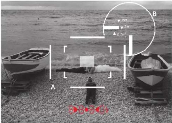
All pictures and brightline frame positions relative to 50mm focal length
| A | Brightline frame |
| B | Actual image fi eld |
| Set to 0.7m: The sensor detects approximately one frame width less. | |
| Set to 2m: The sensor detects exactly the image fi eld shown by the inner edges of the brightline frame. | |
| Set to infinity: The sensor detects approx. 1 or 4 (vertical or horizontal) frame width(s) more. | |
RANGE MEASUREMENT
Due to its large effective metering basis, the rangefinder on this camera is very precise. The benefits of this are particularly noticeable when using wide-angle lenses with their relatively large depth of field.
| Mechanical metering basis (Distance between the optical axes of the viewfinder window and the rangefinder viewing window) | x viewfinder zoom | = Effective metering basis |
| 69.25mm x 0.68 = approx. | 47.1mm |
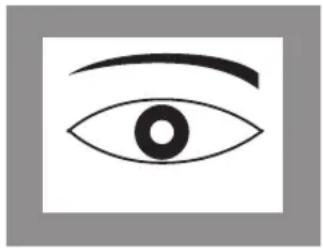
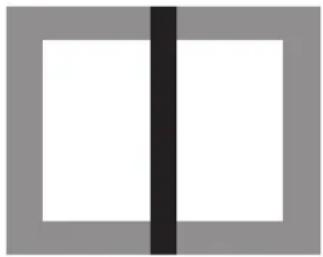
The rangefinder metering field is visible as a bright, sharply defined rectangle in the center of the viewfinder. The focus can be set using either the superimposed image or split image method:
Superimposed image method
In a portrait, for example, aim the metering field at the eye and turn the distance setting ring on the lens until the contours in the metering field are brought into line. Then choose the subject detail.
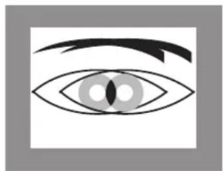
natural_image
Simple line drawing of a human eye with eyelashes and iris (no text or symbols)Out of focus In focus
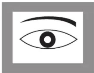
natural_image
Simple line drawing of an eye with eyebrow (no text or symbols)Split image method
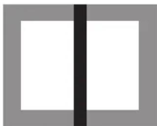
When taking photographs of architecture, for example, aim the rangefinder metering field at the vertical edge or another clearly defined vertical line and turn the distance setting ring on the lens until the contours of the edge or line can be seen at the limits of the metering field with no misalignment.
Then choose the subject detail.
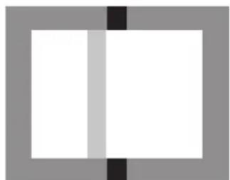
natural_image
Simple geometric composition of two white squares separated by a vertical black line within a gray square frame (no text or symbols)Out of focus In focus
natural_image
Simple geometric diagram with two vertical black lines dividing a square into two white rectangles (no text or symbols)EXPOSURE METERING
On this camera, exposure metering for the available ambient light is carried out through the lens with the working aperture. The light reflected by a bright shutter diaphragm blade in the first shutter curtain is measured. The viewfinder displays either specify the shutter speed / aperture combinations for a correct exposure or can be used to determine them. In aperture priority mode the aperture is selected manually, and the camera then determines the appropriate shutter speed automatically. In this mode a digital LED display indicates the resulting shutter speed (e.g. 1000) If both values are set manually, a light balance made up of three red LEDs (▶●◀) is used to correct the exposure. When the setting is correct, only the central circular LED is lit up.
Turning the exposure meter on/off
The exposure meter is turned on by gently pressing the shutter release to its 1st pressure point, provided the camera is turned on with the main switch and the shutter speed dial is not set to B. The exposure meter is ready for measurement when one of the displays in the viewfinder is continuously lit.
- In aperture priority mode, the digital LED display of the shutter speed, and in manual mode one of the two triangular LEDs lights up, either individually or in conjunction with the center circular LED.
If you let go of the shutter release button without activating the shutter, the exposure meter remains turned on for around 12s more, and the relevant LED(s) remain lit for the same time.
If the shutter speed dial is set to B the exposure meter is disabled.
Notes:
- If the displays go out, the camera is in "standby" mode.
- With very little ambient light, i.e. at the limits of the exposure meter's range, it can take around 0.2s for the LEDs to light up.
- In aperture priority mode, if the correct exposure cannot be achieved using the available shutter speeds, the shutter speed display flashes as a warning (for more details, refer to the “Aperture priority mode” section on p. 93).
- When making manual settings, if you are below the exposure meter's metering range at very low light densities, the left-hand triangular LED flashes as a warning. In aperture priority mode, the shutter speed is still displayed. If the required shutter speed falls below the slowest possible setting of 32s, this display also flashes.
- If the camera is out of use for an extended period or is stored in a case, always turn it off at the main switch. This prevents any power consumption, including that which continues to occur in standby mode after the exposure meter is turned off automatically and the display is extinguished. This also prevents pictures from being taken accidentally.
The appropriate shutter speed for correct exposure, or the variation from a correct exposure setting, are specified or determined using displays in the viewfinder (see following sections).
EXPOSURE MODES
The camera provides two exposure modes: Aperture priority mode and manual mode. Depending on the subject, situation and your individual preferences, you can thus choose between
- the familiar "semi automatic" operation, or
- setting a fixed shutter speed and aperture.
APERTURE PRIORITY
If the shutter speed dial is in the A position the electronics within the camera generate the shutter speed automatically and continuously in the range 14000 s to 60s, in accordance with the film speed setting, the metered brightness and the manually selected aperture. The calculated shutter speed is displayed in half steps to provide a better overview.
For shutter speeds slower than 2s the remaining exposure time is counted down and displayed in seconds after the shutter release. The actually generated and continuously controlled exposure time can however vary from the half step value displayed: For example, if the display shows 16 (the closest value) before releasing the shutter, but the calculated exposure time is longer, the countdown after releasing the shutter may actually start from 19. Under extreme lighting conditions, based on all the parameters the exposure meter may generate a shutter speed that is outside the working range, i.e. brightness values that would require shorter exposures than
^1/_4000 s or longer than 60s. In such cases the specified minimum or maximum shutter speed is nevertheless used, and these values flash in the viewfinder as a warning.
Notes:
- As described in connection with the ISO setting on p. 89, a certain amount of noise becomes apparent when using higher sensitivities, and particularly with uniform dark surfaces. To reduce this annoying phenomenon, after pictures with slow shutter speeds and high ISO values the camera automatically takes a second “black picture” (taken with the shutter closed). The noise present in this parallel picture is then digitally “subtracted” from the data for the real picture. This doubling of the “exposure” time can be significant at longer exposure times, and must be allowed for. During this time the camera should not be turned off.
- If you want a darker or lighter reproduction of the subject, setting the exposure manually is recommended (see p. 94).
EXPOSURE LOCK
For compositional reasons, the most important part of the subject is often not in the center of the picture, and as a result such important parts of the subject may be excessively light or dark. Center-weighted metering captures predominantly or exclusively an area in the center of the image and is calibrated to an average gray scale value.
Subjects and situations of this type can be overcome very easily even in aperture priority mode, using exposure lock.
Using the function
- Aim at the important subject detail or alternatively at another detail with average brightness.
- Press the shutter release button to the 1st pressure point to measure and store the value. As long as the pressure point is held, a small red dot appears in the viewfinder at the top in the digits line for confirmation, and the exposure time no longer changes even if the lighting conditions are different.
- Keeping the shutter release pressed, move the camera to capture the final trimming,
- The shutter can then be released using the exposure originally determined.
Changing the aperture setting after using exposure lock has no effect on the shutter speed, and will lead to an incorrect exposure. Exposure lock is cancelled when you remove your finger from the shutter release pressure point.
MANUAL EXPOSURE SETTING
If the exposure setting is performed entirely manually, the shutter speed dial must be clicked to one of the engraved shutter speeds or to one of the intermediate values.
Then:
- Turn on the exposure meter, and
- turn the shutter speed setting dial and /or the aperture setting ring on the lens - in each case in the direction indicated by the triangular LED that is lit up - until only the circular LED is lit up.
As well as the direction of rotation of the shutter speed setting dial and aperture setting ring necessary for correct exposure, the three LEDs in the light balance also indicate underexposure, overexposure and correct exposure in the following way:
▶ Underexposure by at least one aperture stop; turning to the right is required
Underexposure by 12 aperture stop; turning to the right is required
Correct exposure
Overexposure by ^1/_2 aperture stop; turning to the left is required
Overexposure by at least one aperture stop; turning to the left is required
Note:
For shutter speeds slower than 2s the remaining exposure time is counted down and displayed in seconds after the shutter release.
THE B SETTING
With the B setting, the shutter remains open for as long as the shutter release button is held down (up to a maximum of 60s; depending on the ISO setting).
In both cases, the exposure meter is disabled; after the shutter is released however the digital display in the viewfinder counts the elapsed exposure time in seconds, for guidance.
Notes:
- Long exposure times can be associated with very heavy picture noise.
- To reduce this annoying phenomenon, after pictures with slow shutter speeds (from approx. 1/30s ,) the camera automatically takes a second "black picture" (taken with the shutter closed). The noise present in this parallel picture is then digitally "subtracted" from the data for the real picture.
- This doubling of the “exposure” time can be significant at longer exposure times, and must be allowed for. During this time the camera should not be turned off.
VALUES ABOVE AND BELOW THE METERING RANGE
If the exposure meter reading is below its working range in very low lighting conditions and in manual mode, the left hand triangular LED ( flashes as a warning in the viewfinder, while the right hand LED ( ) does the same if there is too much light. In aperture priority mode, the shutter speed is still displayed. If the required shutter speed is more than the slowest possible 60s or less than the fastest possible ^1/_4000 s, these displays also flash. As the exposure is metered with the working aperture, this situation can come about by stopping down the lens. Even if you are below the metering range, the exposure meter remains on for around 30s after you let go of the shutter release button. If the lighting conditions improve in this time (e.g. due to a change in the subject detail or opening of the aperture), the LED display changes from flashing to continuously lit, indicating that the meter is ready.
FLASH PHOTOGRAPHY
The camera determines the necessary flash power by firing one or more ranging flashes, fractions of a second before taking the actual picture. Immediately after this, at the start of exposure, the main flash is fired. All factors that influence the exposure (such as picture filter and changes to the aperture setting) are automatically taken into account.
COMPATIBLE FLASH UNITS
The following flash units, when used on the camera, are capable of all the functions described in this manual, including TTL flash metering:
- The Leica SF 58 system flash unit. With a maximum guide number of 58 (in 105mm setting), an automatically controlled zoom reflector (with coded Leica M lenses, see p. 81), automatic synchronization with shutter speeds faster than 1HSS for HSS flash (see p. 99), an optional second reflector, and many other functions, it is both powerful and versatile, yet highly user-friendly.
- With its compact dimensions and design that matches the camera, the Leica SF 26 system flash unit is the perfect solution. It is also extremely easy to operate.
- Flash units which meet the technical requirements for System Camera Adaption (SCA) System 3000 and fitted with the SCA-3502-M5 adapter.
Other commercially available flash attachments with standard flash foot and positive center contact, and fired by the center contact (X contact) can also be used.
ATTACHING THE FLASH UNIT
Before attaching a flash unit to the accessory shoe on the camera,
- the cover that protects the accessory shoe when not in use, must be detached to the rear, and
- the camera and flash unit must be turned off.
When attaching a flash unit, you should ensure that the foot of the flash unit is fully inserted into the accessory shoe and the clamping nut is tightened to prevent it accidentally falling out. This is particularly important for flash units with additional control and signal contacts, because if the position in the flash shoe changes the necessary contacts can be broken, leading to malfunctions.
FLASH EXPOSURE CONTROL
Fully automatic flash mode, i.e. controlled by the camera, is available on the camera with the system-compatible flash units listed in the previous section, and in aperture priority A and manual exposure modes.
In addition, automatic illumination regulation is performed in both exposure modes. This means that in order to ensure a balanced relationship between flash and other lighting at all times, the flash power is reduced by up to 1^2/5EV as ambient brightness increases. However, if the ambient brightness plus even the shortest possible flash sync speed of ^1/190s would cause overexposure, a non-HSS compatible flash unit will not be fired in aperture priority mode. In such cases the shutter speed is governed by the ambient brightness and is shown in the viewfinder.
In addition, the camera transfers the set sensitivity to the flash unit.
Provided it has these displays and the aperture set manually on the lens is also entered on the flash unit, this enables the flash unit to automatically adjust its range values accordingly. With system compatible flash units, the sensitivity setting cannot be influenced from the flash unit as it is transferred from the camera.
Notes:
- Studio flash systems may have a very long burning time. Therefore, when using them it may be useful to select a slower shutter speed than 1 / 180S .
- The same applies to radio controlled flash triggers for "unchained flash", as the radio transmission can cause a delay.
- The following sections describe only those settings and functions that are available when using this camera with system-compatible flash units.
- More details of flash use, in particular for other flash units not specially adapted to this camera and for different flash modes can be found in the relevant instructions.
Settings for camera-controlled automatic flash mode
After the flash unit in use has been turned on and set to guide number control mode (e.g. TTL or GNC), the following actions on the camera are necessary:
- Before taking each flash picture, exposure metering is activated by gently pressing the shutter release, i.e. the display in the viewfinder must change to the shutter speed or the light balance. If this stage is missed out by fully depressing the shutter release in one quick movement, the flash unit will not fire even if required.
- The shutter speed dial must be set to A, to the flash sync speed (1/_180s) , or to a slower shutter speed (including B). In aperture priority mode, the camera determines the shutter speed according to the ambient light but limits slow shutter speeds according to the 1/focal length rule to prevent blurring.
- The desired aperture, or the aperture required for the relevant distance to the subject, must be set.
Note:
If the automatically controlled or manually set shutter speed is faster than 1180 s, the flash is not fired unless the flash unit is HSS-compatible (see p.99).
Flash exposure displays in the viewfinder with system-compatible flash units
A flash-shaped LED appears in the viewfinder as confirmation and to display the various operating conditions. This LED appears together with the displays for exposure metering for the ambient light level, described in the relevant sections.
In automatic flash mode
(flash unit set to GNC or TTL)
• does not appear despite the flash unit being switched on and ready for use:
A faster shutter speed than 1180 s is set manually on the camera and the connected flash unit is not HSS-compatible. In such cases the camera will not fire the flash unit even though it is switched on and ready for use.
• flashes slowly (at 2Hz) before the picture is taken:
The flash unit is not yet ready to use
• is lit up before the picture is taken:
The flash unit is ready for use
• Remains continuously lit after taking the picture, and the other displays go out:
The flash exposure was successful, the flash unit remains ready for use.
- #ashes rapidly after taking the picture (at 4Hz), and the other displays go out:
The flash exposure was successful, but the flash unit is not yet ready for further use.
• goes out after taking the picture, together with the other displays:
Underexposure, perhaps due to selecting an aperture stop that is too low for the subject. If the flash unit is set to a partial discharge power, because of the lower power requirement it may be ready for use despite the flash LED not lighting up.
When the flash unit is set to camera control (A) or manual mode (M)
- does not appear despite the flash unit being switched on and ready for use:
An exposure time shorter than 180 s has been set manually on the camera. In such cases the camera will not fire the flash unit even though it is switched on and ready for use. - flashes slowly (at 2Hz) before the picture is taken: The flash unit is not yet ready for use.
- is lit up before the picture is taken: The flash unit is ready for use.
LINEAR FLASH MODE (HIGH SPEED SYNCHRONIZATION)
Fully automatic, i.e. camera controlled, linear flash operation is available with this camera when using the Leica SF 58 flash unit, with all shutter speeds and in aperture priority and manual exposure modes. The camera activates it automatically if the selected or calculated shutter speed is faster than the sync speed, i.e. 11HOS . If the flash unit is set correctly, this change does not require the photographer to do anything else.
Important:
The range for HSS flash is significantly lower than for TTL flash.
Notes:
- With manual exposure control, all shutter speeds up to the sync time of 1 / -80 s can also be set.
- If the Leica SF 58 (see p. 96) is being used and faster shutter speeds than 1/180 s are set on the camera, the flash unit automatically switches to HSS mode.
MISCELLANEOUS
REVIEW
You can review your pictures on a computer. This requires a built-in or connected card reader.
TRANSFERRING DATA TO A COMPUTER
The picture data on the memory card is transferred to a computer using a card reader. You can either use the computer's integrated card reader or an external reader connected using a USB cable.
Data structure on the memory card
Each of the folders 100LEICA, 101LEICA etc. up to 9999 pictures can be stored.
WORKING WITH DNG RAW DATA
For further image editing, you require software designed for the DNG (digital negative) format used, to convert the stored raw data with optimum quality, for example the Adobe ^® Photoshop ^® Lightroom ^® raw data converter. It provides quality-optimized algorithms for digital color processing, delivering exceptionally low noise photographs with incredible resolution.
During editing, you have the option of adjusting parameters such as white balance, noise reduction, gradation, sharpness etc. to achieve an optimum image quality.
Adobe ^® Photoshop ^® Lightroom ^®
Adobe® Photoshop® Lightroom® is available as a free download when you register your camera on the Leica Camera AG website. Further details can be found in the customer area under www.members.leica-camera.com or on the registration card in the camera packaging.
INSTALLING FIRMWARE UPDATES
Leica is constantly working on developing and optimizing its products. As many functions of the camera are entirely controlled by software, some of these improvements and extended functions can be installed at a later date. Leica provides firmware updates at irregular intervals for this purpose. Information about any resulting changes or additions to the details in this manual can be found on our website.
You can download new firmware from our home page and transfer it to your camera:
- Turn off the camera and insert the card into a card reader - either integrated or connected to your computer. Format a memory card.
- Download the Firmware file from our website using the "UPDATES" link.
- Save the file *.FW at the top level of the card's folder structure. Remove the card from your card reader.
- Make sure the camera is turned off, insert the card in the camera, and close the bottom cover.
- Hold down the function button and turn on the camera.
The update process begins. This can take up to 15 minutes.
Displays
| Viewfinder LED(continuously lit) | Rear panel LED | |
| During the process |  | Lit |
| When update is complete |  | Goes out |
| Battery capacity too low for update process |  | Flashing slowly |
| Update not possible* |  | Flashing quickly |
* e.g. because the camera cannot find an update file on the card
SYSTEM ACCESSORIES
INTERCHANGEABLE LENSES
The Leica M system provides a basis for optimum adaptation to fast and unobtrusive photography. The range of lenses incorporates focal lengths from 16 to 135mm and light intensities up to f/0.95.
FILTERS
UVa filters and a universal polarization filter M are available for current Leica M lenses fitted with standard filter thread sizes.
Note:
Leica UV/IR filters specially developed for use on the Leica M8 and M8.2 should not be used on this camera as they can cause color shifts at the edges of pictures, particularly when using wide angle lenses.
UNIVERSAL WIDE ANGLE VIEWFINDER M
The Leica universal wide-angle viewfinder M is a thoroughly practical accessory. It can be used without restriction on all analog and digital Leica M models and – just like the viewfinder in the camera – uses a reflected brightline frame to outline the picture area for wide angle focal lengths 16, 18, 21, 24 and 28mm.
The viewfinder is equipped with parallax compensation and a vial (spirit level) for exact leveling of the camera.
(Order no. 12 011)
MIRROR VIEWFINDER M
Mirror viewfinders are available for 18, 21, and 24mm lenses. They feature an exceptionally compact design and a bright viewfinder image. Brightline frames like those in the camera viewfinder are used to select the trimming (Order no. 18mm: 12 022 black, 12 023 silver / 21mm: 12 024 black, 12 025 silver / 24mm: 12 026 black / 12 027 silver).
VIEWFINDER MAGNIFIERS M 1.25x AND M 1.4x
The Leica M 1.25x and M 1.4x viewfinder magnifiers significantly simplify picture composition when using focal lengths above 35mm. They can be used on all Leica M models and magnify the central area of the viewfinder image. The 1.25x viewfinder magnifier gives the 0.68x viewfinder on this camera a magnification of 0.85x, while the 1.4x gives 0.95x magnification. A security chain with snap fasteners prevents loss and can be used to hang the viewfinder on the carrying strap's fastening ring.
The viewfinder magnifiers are supplied in a leather bag. A loop on the case allows the viewfinder magnifier to be stored on the camera's carrying strap, where it is protected and ready for use.
(Order no. 12 004 M 1.25x, 12 006 M 1.4x)
CORRECTIVE LENSES
For optimum adaptation of the eye to the camera's viewfinder, we offer corrective lenses with the following positive or negative diopter values (spherical): ±0.5/1/1.5/2/3.
FLASH UNITS
With a maximum guide number of 58 (at 105mm setting), an automatically controlled zoom reflector (with coded Leica M lenses, see p. 81), an optional second reflector, automatic synchronization with shutter speeds faster than I_/380 s for HSS flash, and many other functions, the Leica SF 58 system flash unit is both powerful and versatile, yet highly user-friendly. With its compact dimensions and design that matches the camera, the Leica SF 26 system flash unit is the perfect solution. It is also extremely easy to operate.
(SF 58: Order no. 14 488 / SF 26: (Order no. 16 767)
CASES
For extensive camera equipment, the classic waterproof fabric Billingham combination case is the perfect solution. It either holds two cameras and two lenses or one camera and three lenses. There is enough space for even large lenses. A zipped compartment also provides space for a Leica SF 26 flash and for other accessories.
(Order no. 14 854 black, 14 855 khaki)
SPARE PARTS Order no.
| Body cap 420-245.047-000 | |
| Accessory shoe cover 420-245.001-060 | |
| Bottom cover 420-245.050-000 | |
| Protector with carrying strap 439-612.109-000 | |
| Front lens cap 422-502.140-000 | |
| Rear lens cap 422-501.006-000 | |
| Thread protection ring 421-037.001-015 | |
| Lens hood 422-700.028-000 | |
| Lithium ion battery BP-SCL2 14 499 | |
| Charger BC-SCL2(with EU/USA mains cables, in-car charging cord) | 14 494 |
| Mains cable for AUS and UK 14 422 and 14 421 |
LEICA SUMMILUX-M 35MM F/1.4 ASPH. "LEICA 60" Edition
SPECIAL FEATURES
The abbreviation "ASPH" in the name refers to an aspherical lens surface that gives the optical system an unrivaled imaging performance. Even at full aperture, the Leica Summilux-M 35mm f/1.4 ASPH. has outstanding characteristics that are unprecedented for a compact 35mm lens: high contrast, exceptional detail reproduction over the entire image field, good image field flattening and an almost total freedom from coma from an aperture of 2. Stopping down brings hardly any improvement in this excellent imaging performance. The low barrel distortion is normally negligible for practical photography. Like any optical system, the Leica Summilux-M 35mm f/1.4 ASPH. has a certain degree of systematic vignetting. This reduction in light towards the corners of the picture is particularly visible in low lighting and with a uniformly bright image field (e.g. a full format house wall or a blue sky). Vignetting is very low at full aperture and is practically non-existent from f/4. When used on the digital M models, this vignetting can be reduced further if required by a compensation function in the camera itself.
Like all high-powered lenses, at full aperture a violet color fringe can occur at extremely light/dark transitions in the image (e.g. headlights, backlit situations, etc.). This so-called chromatic aberration is due to the system itself and can be eliminated by stopping down by 2-3 stops. If you are using DNG format, many raw data converters (e.g. Adobe ^® Lightroom ^® ) also enable this effect to be eliminated later.
Of the total of 9 lenses - 5 of which are made of highly refractive glass - the rear 5 make up a "floating element", which is moved independently of the other 4 when focusing. This is particularly beneficial in terms of contrast in the close-up range.
Summary: Thanks to its performance features, the Leica Summilux-M 35mm f/1.4 ASPH. can be used for both long-distance and close-up shots, is equally well suited for digital and analog photography, and thus represents a versatile universal wide angle lens.
STRUCTURE OF LEICA M LENSES
All Leica M lenses have essentially the same external construction: they have an aperture setting ring (6), a distance setting ring (11) and a fixed ring (5) with an index for the distance (5a), a depth of field scale (5b), and a red index button for changing lens (5c). In addition, the front mount of the Leica Summilux-M 35 mm f/1.4 ASPH. has an external thread (9) for attaching the lens hood.
The bayonet flange contains a 6-bit barcode lens code, which transfers lens data to the camera body. This aligns it with the exposure metering system on digital Leica M models and optimizes the picture data for the specific lens type.
FOCUSING
The focus is adjusted by turning the focusing ring (11). The finger grip (11a) enables you to work quickly and comfortably.
DEPTH OF FIELD SCALE
The scale (5b) on the fixed ring (5) shows the depth of field range available for the set distance. This is read off using the corresponding vertical lines labeled with the aperture values.
LENS HOOD
The lens includes a detachable lens hood (10).
To attach, the thread protection ring (8) must first be unscrewed (anticlockwise). The lens hood is then screwed on as far as possible (clockwise). The special design of the thread and the lens front mount (7)
- with stop - ensures that the lens hood is correctly aligned. This guarantees that the lens hood does not impair the optical path of the lens or the distance meter, i.e. it prevents vignetting in the image and shadowing in the distance meter measuring field.
When the camera is being carried ready to shoot and during actual use, the lens hood should always remain fitted. It provides effective protection against contrast-reducing stray light and also against damage and soiling of the front lens, e.g. from accidental fingerprints.
Note:
The lens hood must always be screwed on as far as possible.
FILTERS
E46 screw-on filters can be used on the Leica Summilux-M 35mm f/1.4 ASPH. A corresponding UVa filter is available from Leica.
The universal polarizing filter can also be used. The option of pivoting the filter in front of the viewfinder allows you to control the effect through the camera's viewfinder without making any additional settings.
ACCESSORIES Order no.
| Leica E46 UVa filter 13 005 | |
| Leica universal polarizing filter 13 356 |
REPLACEMENTS* Order no.
| Front cover 422-502.140-000 | |
| Rear cover 422-501.006-000 | |
| Thread protection ring 421-037.001-015 | |
| Lens hood 422-700.028-000 |
* Subject to availability
SAFETY AND CARE INSTRUCTIONS
GENERAL PRECAUTIONS
- Do not use your camera in the immediate vicinity of devices with powerful magnetic, electrostatic or electromagnetic fields (e.g. induction ovens, microwave ovens, television sets or computer monitors, video game consoles, cell phones, radio equipment).
- If you place the camera on or very close to a television set, its magnetic field could interfere with picture recordings.
- The same applies for use in the vicinity of cell phones.
- Strong magnetic fields, e.g. from speakers or large electric motors, can damage the stored data or the pictures.
- Do not use the camera in the immediate vicinity of radio transmitters or high-voltage power lines. Their magnetic fields can also interfere with picture recordings.
- If the camera malfunctions due to the effects of electromagnetic fields, remove the battery and turn the camera on again.
- Protect the camera from contact with insect sprays and other aggressive chemicals. Petroleum spirit, thinner and alcohol may not be used for cleaning.
- Certain chemicals and liquids can damage the camera's housing or the surface finish.
-
As rubber and plastics sometimes emit aggressive chemicals, they should not remain in contact with the camera for a long time.
-
Ensure that sand and dust cannot get into the camera, e.g. on the beach. Sand and dust can damage the camera and the memory card. Take particular care when changing lenses and when inserting and removing the card.
- Ensure that water cannot get into the camera, e.g. when it is snowing or raining and on the beach. Moisture can cause malfunctions and even permanent damage to the camera and the memory card.
- Make sure the accessory shoe cover is always fitted when no accessories are in use (such as a flash unit).
- If salt water spray gets onto the camera, wet a soft cloth with tap water, wring it out thoroughly and wipe the camera with it. Then wipe down thoroughly with a dry cloth.
SENSOR
• Cosmic radiation (e.g. on flights) can cause pixel defects.
CONDENSATION MOISTURE
- If condensation has formed on or in the camera, you should turn it off and leave it to stand at room temperature for around an hour. Once the camera temperature has adjusted to room temperature, the condensation will disappear by itself.
CARE INSTRUCTIONS
As any soiling also represents a growth medium for microorganisms, you should take care to keep the equipment clean.
FOR THE CAMERA
- Only clean the camera with a soft, dry cloth. Stubborn dirt should first of all be covered with a well-thinned cleaning agent and then wiped off with a dry cloth.
- To remove stains and fingerprints, the camera and lens should be wiped with a clean lint-free cloth. Tougher dirt in hard to reach corners of the camera body can be removed with a small brush. The shutter blades may not be touched when doing this.
- All mechanically operated bearings and sliding surfaces on your camera are lubricated. Please remember this if you will not be using the camera for a long period of time. To prevent the lubrication points becoming gummed up, the camera shutter should be released a number of times every three months. It is also recommended that you repeatedly move and use all other controls. The range and aperture setting dials on the lens should also be moved periodically.
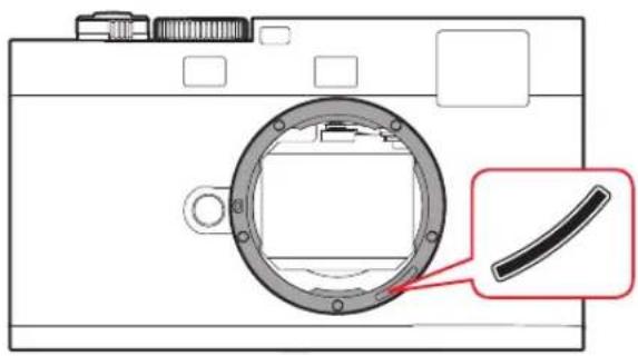
- Take care not to scratch the sensor for the 6-bit coding in the bayonet mount (see p. 81), or to get it dirty. Take care also that no grains of sand or similar particles enter the fastening, where they could scratch the bayonet. Only clean this component when dry and do not exert any pressure on the glass cover.
FOR LENSES
- Normally, a soft hair brush is sufficient to remove dust from the outer lens elements. However, in case of more stubborn dirt, they can be carefully cleaned with a very clean, soft cloth that is completely free of foreign matter, using circular motions from the inside to the outside. We recommend micro-fiber cloths (available from photographic and optical specialists) that are stored in a protective container and can be washed at temperatures of up to 40°C/104°F (without fabric softener, never iron!). Cloths for cleaning glasses, which are impregnated with chemicals, should not be used as they can damage the lens glass.
- Take care not to scratch the 6-bit coding in the bayonet mount, or to get it dirty. Take care also that no grains of sand or similar particles enter the fastening, where they could scratch the bayonet. Never wet this component when cleaning it!
- The bayonet is given an ultra-thin film of grease in the factory to ensure that the lens can be changed easily, gently and smoothly. In normal use, this is retained for many years even if the bayonet is occasionally wiped with a clean cloth. If a substance that dissolves grease is used for cleaning, the grease film must subsequently be replaced. To do this, coat the bayonet with a tiny amount of Vaseline with a finger and spread using a clean cloth.
Important:
Make sure that the bayonet is not excessively lubricated with grease and particularly that the area of the lens identification is clear, as grease residue can accumulate in the gap and collect further dirt. This could impair the legibility of the code and thus restrict camera functions on digital M models.
- For optimum front lens protection in unfavorable photographic conditions (e.g. sand, salt water spray), use transparent UVa filters. However, you should bear in mind that, like all filters, they can cause unwanted reflections in certain backlight situations and with high contrasts. The generally recommended lens hood also protects the lens from unintentional fingerprints and the rain.
- In addition to the type designation, every lens has its "personal" serial number. Note this number in your documentation for security.
FOR THE BATTERY
Rechargeable lithium ion batteries generate power through internal chemical reactions. These reactions are also influenced by the external temperature and humidity. Very high or low temperatures reduce the life of the battery.
- Always remove the battery, if you will not be using the camera for a long period of time. Otherwise, after several weeks the battery could become totally discharged, i.e. the voltage is sharply reduced as the camera still consumes a small amount of current (for saving your settings) even when it is turned off.
- Lithium ion batteries should only be stored in a partially charged condition, i.e. not completely discharged or fully charged (in the corresponding display in the monitor). For very long storage periods, it should be charged up and discharged again around once a year.
- Always ensure that the battery contacts are clean and freely accessible. Whilst lithium ion batteries are proof against short circuits, they should still be protected against contact with metal objects such as paper clips or jewelry. A short-circuited battery can get very hot and cause severe burns.
- If a battery is dropped, check the casing and the contacts immediately for any damage. Using a damaged battery can damage the camera.
- In case of noise, discoloration, deformation, overheating or leaking fluid, the battery must be removed from the camera or charger immediately
and replaced. Continued use of the battery results in a risk of overheating, which can cause fire and/or explosion.
- In case of leaking fluid or a smell of burning, keep the battery away from sources of heat. Leaked fluid can catch fire.
- A safety valve in the battery guarantees that any excess pressure caused by improper handling is discharged safely.
- Batteries have only a limited service life. We recommend replacing them after around four years.
• Take damaged batteries to a collection point to ensure correct recycling. - The batteries may not be exposed to heat, sunlight, humidity or moisture for long periods. Likewise, the batteries may not be placed in a microwave oven or a high pressure container as this results in a risk of fire or explosion.
FOR THE CHARGER
- If the charger is used in the vicinity of radio receivers, it can interfere with the reception; make sure there is a distance of at least 1m between the devices.
- When the charger is in use, it can make a noise (buzzing) – this is quite normal and is not a malfunction.
- When it is not in use, disconnect the charger from the mains as otherwise it uses a certain (very small) amount of power even when no battery is inserted in it.
• Always keep the charger contacts clean, and never short circuit them.
• The car charging cable supplied - may only be operated with 12V electrical systems,
- may never be connected while the charger is connected to the mains.
FOR MEMORY CARDS
- Whilst a picture is being stored or the memory card is being read, it may not be removed, the camera turned off or exposed to vibrations.
- For safety, memory cards should only ever be stored in the anti static cover supplied.
- Do not store memory cards where they will be exposed to high temperatures, direct sunlight, magnetic fields or static discharge.
- Do not drop or bend a memory card as this can damage it and result in loss of the stored data.
- Always remove the memory card if you will not be using the camera for a long period of time.
- Do not touch the connections on the rear of the memory card and keep them free of dirt, dust and moisture.
- It is recommended that the memory card be reformatted from time to time, as fragmentation occurs when deleting, which can block some of the memory capacity.
CLEANING THE SENSOR
If any dust or dirt particles should adhere to the sensor cover glass, depending on the size of the particles this can be identified by dark spots or marks on the pictures.
The camera can be returned to the Leica Camera AG Customer Care department (address: see p. 126) for chargeable cleaning of the sensor; this cleaning is not covered by the guarantee.
However, you can carry out cleaning yourself:
- Turn the main switch clockwise as far as it will go ( ).
- Simultaneously press the shutter release and the function button. The shutter opens, exposing the sensor for cleaning.
Note:
If the battery capacity is too low, the shutter will not open and bc (= battery capacity) appears in the viewfinder to indicate this.
Carrying out cleaning:
Make sure you follow the instructions on the next page.
When cleaning is complete, turn off the camera with the main switch. The shutter closes again after 10s.
Notes:
- Generally, to protect the camera against ingress of dust etc. into the interior of the camera, it is important always to have a lens or a cover fitted to the camera body.
-
For the same reason, when changing lenses work quickly and in an environment that is as dust-free as possible.
-
As plastic parts can easily pick up a static charge and then attract more dust, plastic lens caps and covers should only be stored for short periods in pockets in clothing.
- As far as possible, the sensor should only be cleaned in a dust-free environment to prevent further soiling.
- Lightly adhering dust can be blown off the sensor cover glass using clean and, if necessary ionized gases such as air or nitrogen. It makes sense to use a (rubber) bellows with no brush for this purpose. Special, low pressure cleaning sprays such as "Tetenal Antidust Professional" can also be used in line with their specified usage.
- If the particles cannot be removed from the sensor in this way, consult Leica Customer Service.
- If the battery capacity falls to lower than 30% when the shutter is open, it cannot be closed again as described above, only by turning off the camera.
- Always make sure that the shutter window is clear, i.e. so that no object can obstruct correct closing of the shutter, otherwise damage may occur.
Important:
- Leica Camera AG accepts no liability for damage caused by the user when cleaning the sensor.
- Do not attempt to blow dust particles off the sensor cover glass using your mouth; even tiny droplets of saliva can cause marks that are difficult to remove.
- Compressed air cleaners with high gas pressure may not be used as they can also cause damage.
- Avoid touching the sensor surface with any hard objects during cleaning.
STORAGE
- If you are not using the camera for a longer period of time, we recommend that you:
a. remove the memory card (see p. 78), and
b. remove the battery (see p. 76), (after 2 months at the latest the date and time that were entered will be lost.
- A lens works like a magnifying glass if bright sunlight shines on the front of the camera. The camera must always be protected from strong sunlight. Use the lens cover and keep the camera in the shade (or immediately put it away in the case) help to prevent damage to the interior of the camera.
- You should preferably store the camera in a closed and padded container so that nothing can damage it and it is protected from dust.
- Store the camera in a dry, adequately ventilated place, where neither high temperatures nor high humidity will occur. When used in humid conditions, the camera should be completely free of all moisture before being stored away.
- Photo cases that became wet during use should be emptied to prevent damage to your equipment caused by moisture and any leather-tanning residue released.
-
To prevent fungal growth during use in hot, humid tropical climates, the camera equipment should be exposed to the sun and air as much as possible. Storage in airtight containers or cases is recommended only if a desiccant such as silica gel is placed in the container.
-
To prevent the formation of fungus, do not store the camera in a leather case for long periods of time.
- Note the serial numbers of your camera (engraved on the accessory shoe) and lenses, as these are extremely important in case of loss.
TROUBLESHOOTING
THE CAMERA DOES NOT RESPOND WHEN I TURN IT ON.
- Has the battery been correctly inserted?
- Does the battery have sufficient charge?
Use a charged battery.
- Has the bottom cover been correctly fitted?
THE CAMERA TURNS ITSELF OFF AGAIN AS SOON AS I TURN IT ON.
- Does the battery have sufficient charge to operate the camera? Charge the battery or insert a charged battery.
- Is there any condensation?
This occurs if the camera is moved from a cold place to a hot place. In this case, wait until the condensation has evaporated.
THE CAMERA SHUTTER REFUSES TO TRIP.
– Picture data is currently being transferred to the memory card and the back-up memory is full.
- The capacity of the memory card is exhausted and the back-up memory is full.
- No memory card has been inserted and the back-up memory is full.
I CANNOT SAVE THE PICTURE.
- Is a memory card inserted?
- The memory card is full.
THE DATE AND TIME DISPLAYS SHOW INCORRECT VALUES OR ARE BLANK.
- The camera has not been used for a long period, particularly if the battery has been removed.
Insert a fully charged battery.
Set the date and time.
APPENDIX
DISPLAYS IN THE VIEWFINDER
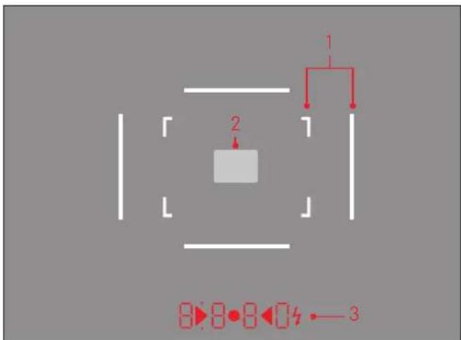
-
Brightline frames for 50mm and 75mm ^-1 (example)
-
Metering field for distance setting
-
LEDs (Light Emitting Diodes) for:
a. Four-digit digital display with dots above and below
8880Digital display:
- Display of the automatically determined shutter speed for aperture priority mode A, or for counting down shutter speeds slower than 1s
- Warning that the metering or setting ranges are overshot or undershot using aperture priority A
– Date/time display (during setting only) - Indicates that the back-up memory is (temporarily) full
- Indicates that no memory card is loaded (5d)
- Indicates that the memory card is full (Full)
- Indicates insufficient battery capacity (bc)
- Indicates that a firmware update is in progress or is complete (UP)
- Firmware update not possible (Err)
b. Dot above:
- Indicates (when lit) that saved metering values are being used
– Indicates the date display (during setting only)
c. Dot below:
- Indicates (flashing) that exposure compensation is being used
– Indicates the time display (during setting only)
d. ▶ ● ◀ Two triangular and one circular LED:
- For manual exposure setting: Jointly used as light balance for exposure compensation The triangular LEDs give the direction of rotation of the aperture setting ring and shutter speed setting dial to adjust the exposure.
- Warning of values below the metering range
e. Flash symbol:
- Flash ready to use
- Details of flash exposure before and after the picture
MTF DIAGRAMS
The MTF is specified for full stop and for apertures 2.8 and 5.6 for long image distances (infinity). The contrast in percent is applied for 5, 10, 20, 40 Lp/mm above the height of the 35mm film for tangential (dotted line) and sagittal structures (continuous line) with white light. The 5 and 10 Lp/mm give an impression of the contrast behavior for rougher object structures, while 20 and 40 Lp/mm document the resolution capabilities for fine and ultra-fine object structures.
Saggital structures
Tangential structures
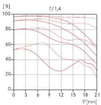
line
| Y'[mm] | Line 1 | Line 2 | Line 3 | Line 4 | Line 5 | Line 6 | Line 7 | Line 8 | | ------ | ------ | ------ | ------ | ------ | ------ | ------ | ------ | ------ | | 0 | 95 | 90 | 85 | 80 | 75 | 70 | 65 | 60 | | 3 | 94 | 89 | 84 | 79 | 74 | 70 | 66 | 61 | | 6 | 93 | 88 | 83 | 78 | 73 | 69 | 65 | 62 | | 9 | 92 | 87 | 82 | 77 | 72 | 68 | 64 | 63 | | 12 | 91 | 86 | 81 | 76 | 71 | 67 | 63 | 62 | | 15 | 90 | 85 | 80 | 75 | 70 | 66 | 62 | 61 | | 18 | 89 | 84 | 79 | 74 | 69 | 65 | 61 | 60 | | 21 | 88 | 83 | 78 | 73 | 68 | 64 | 60 | 59 |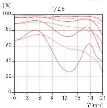
line
| Y'[mm] | Line 1 | Line 2 | Line 3 | Line 4 | Line 5 | Line 6 | Line 7 | Line 8 | | ------ | ------ | ------ | ------ | ------ | ------ | ------ | ------ | ------ | | 0 | 90 | 85 | 80 | 75 | 70 | 65 | 60 | 55 | | 3 | 92 | 88 | 83 | 78 | 73 | 68 | 63 | 58 | | 6 | 94 | 90 | 86 | 80 | 75 | 70 | 65 | 60 | | 9 | 96 | 92 | 88 | 83 | 78 | 73 | 68 | 63 | | 12 | 98 | 94 | 90 | 85 | 80 | 75 | 70 | 65 | | 15 | 99 | 96 | 92 | 88 | 83 | 78 | 73 | 68 | | 18 | 98 | 94 | 90 | 85 | 80 | 75 | 70 | 65 | | 21 | 96 | 92 | 88 | 80 | 75 | 70 | 65 | 60 |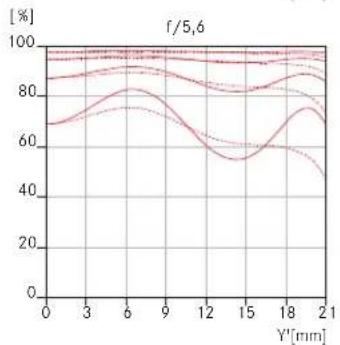
line
| Y'[mm] | Line 1 | Line 2 | Line 3 | Line 4 | Line 5 | | ------ | ------ | ------ | ------ | ------ | ------ | | 0 | 85 | 80 | 70 | 90 | 95 | | 3 | 88 | 82 | 75 | 92 | 96 | | 6 | 90 | 85 | 80 | 94 | 97 | | 9 | 92 | 88 | 85 | 96 | 98 | | 12 | 94 | 90 | 90 | 98 | 99 | | 15 | 96 | 92 | 95 | 100 | 100 | | 18 | 98 | 94 | 98 | 100 | 100 | | 21 | 100 | 96 | 100 | 100 | 100 |DISTORTION DIAGRAMS
Distortion describes the variation in the actual image height from the ideal height, with the ideal image height calculated from the object height and the reproduction scale. Relative distortion specifies the percentage variation of the actual image height from the ideal. The image height 21.6mm is the radial distance between a corner of the image field and the center of the image (image format 24mm x 36mm). The graphical representation of the effective distortion illustrates the actual course or curvature of horizontal and vertical lines in the image plane.
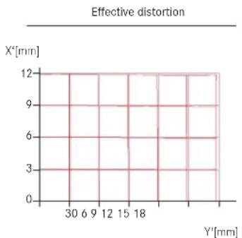
line
| Y' [mm] | X' [mm] | | ------- | ------- | | 30 | 12 | | 6 | 12 | | 9 | 12 | | 12 | 12 | | 15 | 12 | | 18 | 12 | | 21 | 12 |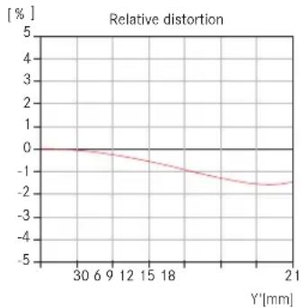
line
| Y'[mm] | Relative distortion [%] | | ------ | ---------------------- | | 30 | 0 | | 6 | -0.5 | | 9 | -1 | | 12 | -1.5 | | 15 | -2 | | 18 | -2.5 | | 21 | -3 |VIGNETTING DIAGRAM
Vignetting describes the continuous reduction in the brightness of an image (intensity) towards the edge of the image (edge shading, darkening of corners of image). The graphic plots the percentage reduction in brightness against the image height. At 100% no vignetting occurs.
$$ \begin{array}{l} _ 5. 6 \ - - - - 2. 8 \ \dots 1. 4 \ \end{array} $$
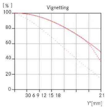
line
| Y'[mm] | Solid Line [%] | Dashed Line [%] | | ------ | -------------- | --------------- | | 30 | 100 | 100 | | 6 | 98 | 95 | | 9 | 95 | 90 | | 12 | 90 | 85 | | 15 | 85 | 80 | | 18 | 80 | 75 | | 21 | 75 | 70 |INDEX
Battery, inserting and removing 76
Viewfinder displays 114
Storage 111
Shutter release button, see Shutter and Technical Data 85
Exposure / Exposure control / Exposure meter
Switching off 85
Turning on 93
Sensitivity 89
Manual setting 94
Metering range....95/120
Values above and below the metering range 96
Metering memory lock 94
Aperture priority....93
Designation of parts 72
Aperture setting ring 72
Flash mode 96
Flash units 96
Data structure on the memory card 100
Transferring data to a computer.... 100
DNG 89/100
Turning on / off 84
Sensitivity 89/121
Distance setting 91
Setting ring 72
Rangefinder 90/91
Metering field 116
Superimposed image method 91
Split image method 91
Spare parts 103
Malfunctions and their resolution 112
Filters 102
Firmware downloads 101
Format frame 90/114
Lens hood 105
Main switch 84
HSS flash 99
Info service, Leica Product Support 126
ISO sensitivity 89/121
Corrective lenses 102
Customer service / Customer Care 126
Brightline view- and rangefinder 90
Package contents....125
Linear flash (HSS) 99
Lenses, Leica M 81
Attaching and removing 83
Structure 72
Use of older lenses 81
Care instructions 106
Protector 74
Repairs / Leica Customer Care 126
Raw data....89/100
Depth of field scale 72
Memory card, inserting and removing.... 76
Viewfinder....90
Displays 114
Detachable viewfinders 102
Brightline frame 90/114
Cases 103
Technical data 120
Parts, designation 72
Carrying strap 74
Time and date 88
Shutter, see Shutter release and Technical Data
Care instructions 104
Warning messages 70
Interchangeable lenses 81/102
Aperture priority 93
Shutter speed setting dial 86
TECHNICAL DATA
LEICA 60
Camera type
Leica M EDITION 60 (Typ 240), compact digital view and rangefinder system camera
Lens attachment
Leica M bayonet with additional sensor for 6-bit coding.
Lens system
Leica M lenses from 16 - 135mm
Picture format / Image sensor
CMOS chip, active area approx. 23.9 x 35.8mm (corresponds to the usable format of analog Leica M models)
Resolution
5976 x 3992 pixel (24MP)
Data format
DNG ^TM (raw data), uncompressed
File size
48.2MB
Color space
Adobe® RGB
White balance
Automatic
Storage medium
SD cards up to 2 GB / SDHC cards up to 32 GB / SDXC cards
Exposure metering
Through the Lens (TTL) metering at the effective aperture, center-weighted TTL metering for flash exposure with system-compliant SCA-3000/2 standard flash units
Metering principle / method
For metering the light reflected by the gray blades of the 1st shutter curtain onto a measuring cell: strongly center weighted.
Metering range
(at ISO 200) At room temperature and normal humidity, corresponds to EV 0 to 20 and aperture 1.0 and 1.2s to aperture 32 and ^1/_1000 s. Flashing of the left triangular LED in the viewfinder indicates values below the metering range.
Sensitivity range
ISO 200 to ISO 6400, manually adjustable in 1 / _3 ISO increments
Exposure mode
Choice of automatic shutter speed control with manual aperture preselection - aperture priority A, or manual shutter speed and aperture setting
Flash exposure control
Flash unit attachment
Via accessory shoe with center and control contacts
Synchronization
With 1st shutter curtain
Flash sync time
= 1 / _180S ; slower shutter speeds possible below sync speed: automatic switch to TTL linear flash operation with HSS compatible Leica system flash units
Flash exposure metering
(with SCA-3000 standard flash units, e.g. Leica SF 26/Leica SF 58) Control with center-weighted TTL pre-flash metering
Flash exposure compensation
On Leica SF 58: in all modes ±3EV in 1/3 EV increments
Displays in flash mode
Ready: Flash symbol LED constantly lit in viewfinder.
Success confirmation: LED stays lit or briefly flashes quickly after taking the picture.
Underexposure: LED temporarily goes out.
Viewfinder
Viewfinder principle
Large, brightline frame viewfinder with automatic parallax compensation.
Eyepiece
Calibrated to -0.5 dpt.; corrective lenses from -3 to +3 diopter available.
Frame indication
By activating two brightline frames each: For 35 and 135mm, 28 and 90mm or 50 and 75mm; automatic switching when lens is attached; frame illumination color: white.
Parallax compensation
The horizontal and vertical difference between the viewfinder and the lens is automatically compensated by shifting the brightline frames according to the relevant distance setting.
Matching viewfinder and actual image
At a range setting of 2m, the brightline frame sizes correspond exactly to the sensor size of approx. 23.9 × 35.8mm ; at infinity setting, depending on the focal length, approx. 7.3% (28mm) to 18% (135mm) more is recorded by the sensor than indicated by the corresponding brightline frame and slightly less for shorter distance settings than 2m
Magnification (For all lenses)
0.68 x
Large-basis rangefinder
Split or superimposed image rangefinder shown as a brightfield in the center of the viewfinder image
Effective metering basis
47.1 mm (mechanical measurement basis 69.25 mm x viewfinder magnification 0.68x)
Displays
In the viewfinder
Four-digit digital display with dots above and below, see p. 114
Shutter and shutter release button
Shutter
Metal blade focal plane shutter
Shutter speeds
For aperture priority: (A) continuous from 32s to 14000 s., For manual setting: 8s to 14000 s in half steps,
B: For long exposures up to maximum 60s, ^-1 / 180s : Fastest shutter speed for flash synchronization, HSS linear flash mode possible with all shutter speeds faster than ^1 / 180s with Leica system flash units with corresponding features
Cocking the shutter
By integrated motor, low noise operation
Shutter release button
Two-stage, 1. Activation of exposure metering and exposure lock (in aperture priority mode), 2. Shutter release
Turning the camera on/off
Using main switch on top of camera; automatic shutdown of camera electronics after approx. 2 minutes; reactivated by tapping the shutter release
Power supply
1 lithium ion battery, nominal voltage 7.4V, capacity 1800mAh; capacity indicated in viewfinder, operating conditions (in camera): 0^-40^ / 32^-104^ ; Model no.: BP-SCL2. Manufacturer: PT. VARTA Microbattery Indonesia, made in Indonesia
Charger
Inputs: 100-240V AC, 50/60Hz, automatic switching, or 12V DC, 1.3A; Output: DC nominal 7.4V, 1000mA / maximum 8.25V, 1100mA, operating conditions (charging): 10°-30°C / 50°-86°F; Model no.: BC-SCL2. Manufacturer: Guangdong PISEN Electronics Co., Ltd., made in China
Camera body
Material
Housing: Stainless steel and light metal alloy, 100% calf leather cover, clear lacquer
Tripod thread
A 14 ( 14 ) DIN stainless steel in bottom
Operating conditions
0^-40^/32^-104^
Interface
ISO accessory shoe
Dimensions
(Width x Depth x Height) approx. 138.6 x 42 x 80mm
Weight
approx. 720g (with battery)
LEICA SUMMILUX-M 35 mm f/1.4 ASPH.
Angle of view (diagonal, horizontal, vertical) Approx. 63°, 54°, 38°
Optical design
Number of lenses / groups 9 / 5
Aspherical surfaces 1
Position of entry pupil (in light incidence direction behind bayonet flange) 22.4mm
Distance setting
Working range 0.7m to ∞
Scale Meter/feet graduation
Smallest object field / largest scale
approx. 420x630mm/1:17.5
Aperture
Adjustment / function Locking aperture, half values adjustable Lowest value 16
Bayonet Leica M quick change bayonet with 6-bit barcode lens identification for digital M models
Filter mount / lens hood Non-rotating, female thread for E46 screw-in filter, male thread with stop for screw-on lens hood or thread protection ring (both supplied)
Viewfinder Camera viewfinder
Design Stainless steel
Dimensions and weight
Length to bayonet support 45.8/59.5mm (without/with lens hood) Maximum diameter approx. 56mm
Weight approx. 439g
Compatible cameras All Leica M models
Package contents
Charger 100-240V with 2 mains cables (Euro, USA, varies in some export markets), Lithium ion battery, carrying strap, body bayonet cap, cover for accessory shoe, Adobe® Photoshop® Lightroom® license, lens front and rear caps, thread protection ring, lens hood
Subject to changes to design, manufacture and range.
LEICA PRODUCT SUPPORT
The Product Support department at Leica AG can provide you with an answer to any technical questions relating to Leica products, including software supplied, either in writing, on the telephone or by e-mail. They are also the contact point for purchasing advice and to order instruction manuals. Alternatively, you can send us your questions using the contact form on the Leica Camera AG homepage.
Leica Camera AG
Product Support / Software Support
Am Leitz-Park 5
D-35578 Wetzlar
Telephone: +49(0)6441-2080-111 /-108
Fax: +49(0)6441-2080-490
info@leica-camera.com / software-support@leica-camera.com
LEICA CUSTOMER CARE
For servicing your Leica equipment or in the event of damage, the Leica Camera AG Customer Care department or the repair service provided by authorized Leica agents in your country are available (see the Guarantee Card for a list of addresses).
Leica Camera AG
Customer Care
Am Leitz-Park 5
D-35578 Wetzlar
Telephone: +49(0)6441-2080-189
Fax: +49(0)6441-2080-339
customer.care@leica-camera.com

natural_image
Diagram of a mechanical component with a red arrow indicating rotation, no text or symbols present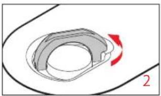
natural_image
Diagram of a mechanical component with a red arrow indicating rotation, no text or symbols present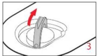
natural_image
Diagram of a mechanical component with a red arrow indicating direction, no text or symbols present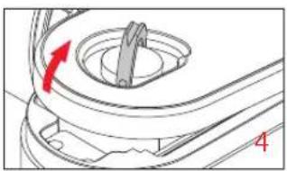
natural_image
Mechanical component diagram showing a knob and handle with red directional arrow (no text or symbols)バッテリーの入れ方
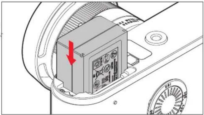
natural_image
Diagram of a mechanical device with a red arrow pointing to a component, no visible text or symbolsバッテリーの取り出し方
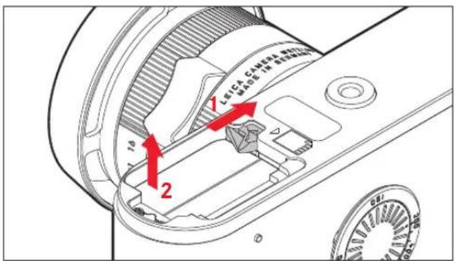
バッテリー残量表示
natural_image
Technical diagram of a mechanical component with a red arrow indicating a specific part (no text or symbols present)メモリーカードの取り出し方
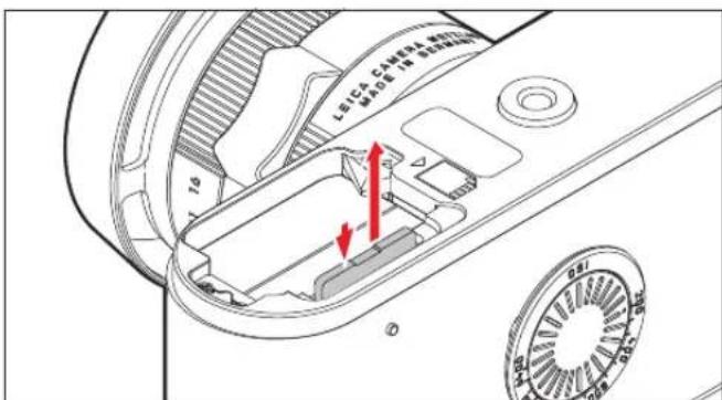
メモリーカード容量表示
natural_image
Mechanical assembly diagram showing a gear-like component with red arrows indicating motion or force direction (no text or symbols)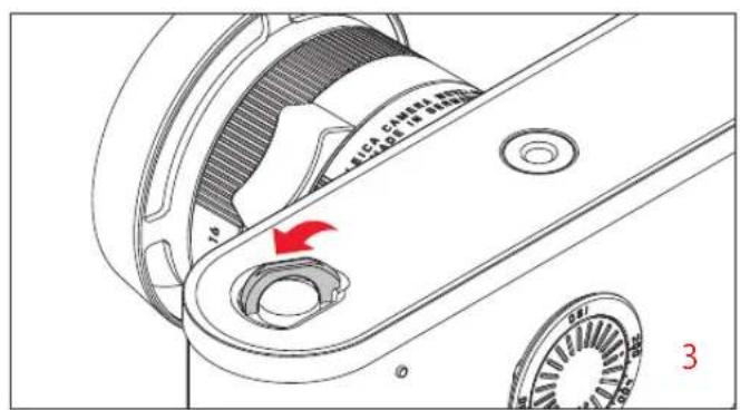
natural_image
Mechanical component diagram showing a gear assembly with a red arrow indicating rotation (no text or symbols)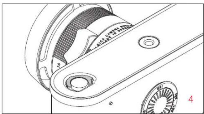
natural_image
Technical line drawing of a mechanical assembly with gears and housing (no text or symbols)ライカMレンズ
natural_image
Diagram of a camera lens with a magnified inset showing the aperture and blade (no text or symbols)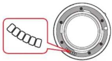
重要
・装着できないレンズ
natural_image
Simple line drawing of a human eye with eyelashes and iris (no text or symbols)ピントが外れている ピントが合っている
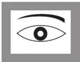
natural_image
Simple line drawing of an eye with eyebrow (no text or symbols)スプリットイメージ式
natural_image
Simple geometric composition with two white squares separated by a vertical black line (no text or symbols)ピントが外れている ピントが合っている
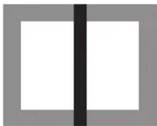
natural_image
Two white rectangular panels separated by a vertical black line, with gray borders (no text or symbols)露出計
- LEICA M-OBJEKTIVE
- Wichtig:
- Schnittbildmethode
- BELICHTUNGSMESSUNG
- LEICA CUSTOMER CARE
- FCC Note: (U. S. only)
- FCC Caution:
- LEICA M EDITION 60 (Typ 240)
- CONTENTS
- Preparations
- Controls
- Basic settings
- Miscellaneous
- System accessories
- Replacements
- Leica Summilux-M 35mm f/1.4 ASPH.
- Precautions and care instructions
- Malfunctions and their resolution ....112
- Appendix
- Index 118
- WARNING MESSAGES
- LEGAL INFORMATION
- DISPOSAL OF ELECTRICAL AND ELECTRONIC EQUIPMENT
- DESIGNATION OF PARTS
- Front view
- Top view
- Rear view
- Bottom view
- USING THE PROTECTOR
- CHARGING THE BATTERY
- Note:
- Caution:
- Notes:
- CHANGING THE BATTERY AND MEMORY CARD
- Important:
- Charge level displays
- Memory card capacity display
- Compatible memory cards
- Close the bottom cover
- LEICA M LENSES
- Attaching the lens
- Detaching the lens
- SHUTTER RELEASE
- SHUTTER SPEED SETTING DIAL
- SETTING THE DATE AND TIME
- The procedure is the same for all fi ve values:
- SETTING THE ISO SENSITIVITY
- FIXED CAMERA SETTINGS
- BRIGHTLINE VIEW- AND RANGEFINDER
- RANGE MEASUREMENT
- Superimposed image method
- Split image method
- EXPOSURE METERING
- Turning the exposure meter on/off
- EXPOSURE MODES
- APERTURE PRIORITY
- EXPOSURE LOCK
- Using the function
- MANUAL EXPOSURE SETTING
- THE B SETTING
- VALUES ABOVE AND BELOW THE METERING RANGE
- FLASH PHOTOGRAPHY
- COMPATIBLE FLASH UNITS
- ATTACHING THE FLASH UNIT
- FLASH EXPOSURE CONTROL
- Settings for camera-controlled automatic flash mode
- Flash exposure displays in the viewfinder with system-compatible flash units
- In automatic flash mode
- When the flash unit is set to camera control (A) or manual mode (M)
- LINEAR FLASH MODE (HIGH SPEED SYNCHRONIZATION)
- REVIEW
- TRANSFERRING DATA TO A COMPUTER
- Data structure on the memory card
- WORKING WITH DNG RAW DATA
- Adobe ® Photoshop ® Lightroom ®
- INSTALLING FIRMWARE UPDATES
- INTERCHANGEABLE LENSES
- FILTERS
- UNIVERSAL WIDE ANGLE VIEWFINDER M
- MIRROR VIEWFINDER M
- VIEWFINDER MAGNIFIERS M 1.25x AND M 1.4x
- CORRECTIVE LENSES
- FLASH UNITS
- CASES
- LEICA SUMMILUX-M 35MM F/1.4 ASPH. "LEICA 60" Edition
- SPECIAL FEATURES
- STRUCTURE OF LEICA M LENSES
- FOCUSING
- DEPTH OF FIELD SCALE
- LENS HOOD
- SAFETY AND CARE INSTRUCTIONS
- GENERAL PRECAUTIONS
- SENSOR
- CONDENSATION MOISTURE
- CARE INSTRUCTIONS
- FOR THE CAMERA
- FOR LENSES
- FOR THE BATTERY
- FOR THE CHARGER
- FOR MEMORY CARDS
- CLEANING THE SENSOR
- However, you can carry out cleaning yourself:
- Carrying out cleaning:
- STORAGE
- TROUBLESHOOTING
- THE CAMERA DOES NOT RESPOND WHEN I TURN IT ON.
- THE CAMERA TURNS ITSELF OFF AGAIN AS SOON AS I TURN IT ON.
- THE CAMERA SHUTTER REFUSES TO TRIP.
- I CANNOT SAVE THE PICTURE.
- THE DATE AND TIME DISPLAYS SHOW INCORRECT VALUES OR ARE BLANK.
- DISPLAYS IN THE VIEWFINDER
- MTF DIAGRAMS
- DISTORTION DIAGRAMS
- VIGNETTING DIAGRAM
- INDEX
- TECHNICAL DATA
- LEICA 60
- Camera type
- Lens attachment
- Lens system
- Picture format / Image sensor
- Resolution
- Data format
- File size
- Color space
- White balance
- Storage medium
- Metering principle / method
- Metering range
- Sensitivity range
- Exposure mode
- Flash unit attachment
- Synchronization
- Flash sync time
- Flash exposure metering
- Flash exposure compensation
- Displays in flash mode
- Viewfinder
- Viewfinder principle
- Eyepiece
- Frame indication
- Parallax compensation
- Matching viewfinder and actual image
- Large-basis rangefinder
- Effective metering basis
- Displays
- In the viewfinder
- Shutter and shutter release button
- Shutter
- Shutter speeds
- Cocking the shutter
- Shutter release button
- Turning the camera on/off
- Power supply
- Charger
- Camera body
- Material
- Tripod thread
- Operating conditions
- Interface
- Dimensions
- Weight
- LEICA SUMMILUX-M 35 mm f/1.4 ASPH.
- Optical design
- Distance setting
- Aperture
- Dimensions and weight
- Package contents
- LEICA PRODUCT SUPPORT
- バッテリー残量表示
- メモリーカードの取り出し方
- メモリーカード容量表示
- ライカMレンズ
- 重要
- スプリットイメージ式
- 露出計
Brand : LEICA
Model : M (Edition 60)
Category : Camera