
CB-501B - Car radio Overmax - Free user manual and instructions
Find the device manual for free CB-501B Overmax in PDF.


| Product Type | 2-way CB mobile radio |
| Model | CB-501B |
| Brand | Overmax |
| Channels | 40 |
| Frequency Range | 26.960 to 27.400 MHz |
| Frequency Control | Phase-Locked Loop (PLL) synthesizer |
| Frequency Tolerance | 0.005% |
| Operating Temperature Range | -30°C to +50°C |
| Microphone | Plug-in type; Electret condenser |
| Input Voltage | 13.8V DC nominal (negative ground) |
| Current Drain (Transmit) | AM full mod., 1.5A (maximum) |
| Current Drain (Receive) | Squelched 0.115A, full audio output 1.0A (normal) |
| Dimensions (D x W x H) | 131mm x 171mm x 44.5mm |
| Weight | 3 lbs 4 oz (1.0 kg) |
| Antenna Connector | UHF, SO-239 |
| Semiconductors | 22 transistors, 17 diodes, 3 integrated circuits, 3 LEDs |
| Meter | Indicates relative power output and received signal strength |
| Transmitter Power Output | 4 watts |
| Modulation | High- and low-level Class B amplitude |
| Frequency Response | 300 to 3000 Hz |
| Output Impedance | 50 ohms, unbalanced |
| Output Protection | Output transistors protected against mismatch up to 20:1 |
| Receiver Sensitivity | Less than 1 μV for 10dB (S+N)/N |
| Selectivity | 6dB typical |
| Adjacent Channel Rejection | 50dB typical |
| IF Frequency | Double conversion, 1st: 10.695 MHz, 2nd: 455 KHz |
| AGC | Less than 10dB change in audio output for inputs from 10 to 50,000 μV |
| Squelch | Adjustable; threshold less than 1 μV |
| Audio Output Power | 3 watts |
| Distortion | Less than 10% @ 3 watts @ 1000Hz |
| Built-in Speaker Impedance | 16 ohms, round |
| External Speaker Impedance | 8 ohms (disables internal speaker when connected) |
| PA System Power Output | 4 watts into external speaker |
| Features | Instant Channel 9 selection, CB/PA switch, Automatic Noise Limiter, Channel up/down buttons, Volume/Squelch controls, S-RF/Power Meter, TX indicator, Channel display |
| Mounting | Universal mounting bracket with thumb screws |
| Safety | Use only specified 2A fuse; do not operate without antenna; do not connect directly to 120V AC; follow FCC rules |
| Maintenance | Check connections, fuse, microphone, antenna SWR; replace parts only with identical parts |
Frequently Asked Questions - CB-501B Overmax
User questions about CB-501B Overmax
0 question about this device. Answer the ones you know or ask your own.
Ask a new question about this device
Download the instructions for your Car radio in PDF format for free! Find your manual CB-501B - Overmax and take your electronic device back in hand. On this page are published all the documents necessary for the use of your device. CB-501B by Overmax.
USER MANUAL CB-501B Overmax
INSTRUKCJA OBSŁUGI
2-ZAKRESOWE PRZENOŚNE RADIO CB PASMA OBYWATELSKIEGO
MODEL OV-CB-501B
Wprowadzenie
natural_image
Technical line drawing of a mechanical assembly with gears and a rectangular base (no text or symbols)C. Panel tylny
Your CB radio Provides high-level, trouble-free performance over the following frequency assignments:
| Channel | Frequency | Frequency | |
| in MHz | Channel | in MHz | |
| 1 | 26.960 | 21 | 27.210 |
| 2 | 26.970 | 22 | 27.220 |
| 3 | 26.980 | 23 | 27.250 |
| 4 | 27.000 | 24 | 27.230 |
| 5 | 27.010 | 25 | 27.240 |
| 6 | 27.020 | 26 | 27.260 |
| 7 | 27.030 | 27 | 27.270 |
| 8 | 27.050 | 28 | 27.280 |
| 9 | 27.060 | 29 | 27.290 |
| 10 | 27.070 | 30 | 27.300 |
| 11 | 27.080 | 31 | 27.310 |
| 12 | 27.100 | 32 | 27.320 |
| 13 | 27.110 | 33 | 27.330 |
| 14 | 27.120 | 34 | 27.340 |
| 15 | 27.130 | 35 | 27.350 |
| 16 | 27.150 | 36 | 27.360 |
| 17 | 27.160 | 37 | 27.370 |
| 18 | 27.170 | 38 | 27.380 |
| 19 | 27.180 | 39 | 27.390 |
| 20 | 27.200 | 40 | 27.400 |
These frequencies generated and accurately controlled by a phase lock hoop (PLL) circuit, comprised of the latest state-of-the-art integrated circuit technology, ensuring high reliability and excellent frequency stability on the above channels.
To obtain maximum performance please read carefully the descriptions and operating instructions in this manual.
Specifications
| GENERAL | |
| Channels | 40 |
| Frequency Range | 26.960 to 27.400MHz |
| Frequency Control | Phase-Locked Loop (PLL) synthesizer |
| Frequency Tolerance | 0.005% |
| Operating Temp. Range | -30°C to +50°C |
| Microphone | Plug-in type; Electret condenser |
| Input Voltage | 13.8V DC nom. (negative ground) |
| Current Drain | Transmit: AM full mod., 1.5A (maximum).Receive: (Squelched, 0.115A, full audio output 1.0A (normal) |
| Size | 131mm(D)×171mm(W)×44.5mm(H) |
| Weight | 3lbs., 4 oz (1.0Kg) |
| Antenna Connector | UHF, SO-239 |
| Semiconductors | 22 transistors, 17 diodes, 3 integrated circuits,3 LEDs. |
| Meter | Indicates relative power output and received signal strength |
| TRANSMITTER | |
| Power Output | 4 watts |
| Modulation | High- and low-level Class B amplitude |
| Frequency | 300 to 3000Hz |
| Output Impedance | 50 ohms, unbalanced |
| Output Protection | Output transistors protected against mismatch up to 20:1 |
| RECEIVER | |
| Sensitivity | Less than 1 μV for 10dB (S+N)/N |
| Selectivity | 6dB typical |
| Adjacent CH. Rejection | 50dB typical |
| IF Frequency | Double conversion, 1st: 10.695 MHz2st: 455KHz |
| Automatic Gain Control (AGC) | Less than 10dB change in audio output for inputs from 10 to 50,000 μV |
| Squelch | Adjustable; threshold less than 1 μV |
| Audio Output Power | 3 watts |
Frequency Response
300-3000Hz
Distortion
Less than 10% @ 3 watts @ 1000Hz
Built-in Speaker
16 ohms, round
External Speaker
8 ohms; disable internal speaker when connected
(Not Supplied)
PA SYSTEM
Power Output
4 watts into external speaker
External Speaker for PA Supplied)
8 ohms; a separate jack is provided (Not
(Specification Subject to change without notice)
Installation
Location
Plan the location of the transceiver and microphone bracket before starting the installation. Select a location that is convenient for operation and does not interfere with the driver or passengers in the vehicle. In automobiles, the transceiver is usually mounted to the underneath of the dash panel, with the microphone bracket beside it.
Mounting Connection
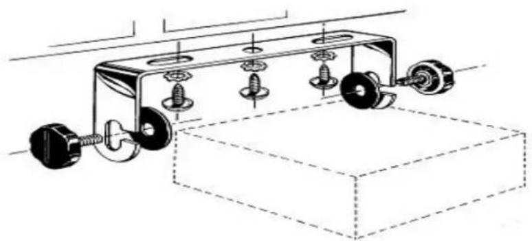
The transceiver is held in the universal mounting bracket by two thumb screws, permitting adjustment at the most convenient angle.
A universal mounting bracket is supplied along with self tapping screws and star washers. The mounting must be mechanically strong and also provide a good electrical connection to the chassis of the vehicle. To mount the transceiver:
-
Determine the most convenient location in your vehicle. Hold the radio with mounting bracket in the exact location desired. If nothing will interfere with mounting it in the desired position, remove the mounting bracket and use it as a template to mark the location for the mounting screws.
-
Drill necessary holes and secure mounting bracket in location.
natural_image
Technical line drawing of a mechanical assembly with gears and a base plate (no text or symbols)- Connect the antenna cable plug to the standard receptacle on the unit. Most CB antennas are terminated with a type PL-259 plug which mates with the receptacle marked "ANT."
- Connect the red lead of DC power cord to +13.8VDC. In automobile installations, +13.8VDC is usually obtained from the accessory contact in the fuse box. This prevents the set being left on accidentally and also permits operating the unit without the vehicle's engine running. Before installing the CB radio, visually check the vehicle battery connections to determine which battery terminal, positive or negative (positive is the larger of the two) is grounded to the engine block (or chassis).
- Connect the black lead to the negative side of the automobile. This is usually the chassis of the car. Any convenient location with good electrical contact (remove paint) may be used.
- Mount the microphone bracket on right side of the transceiver, or near it using two screws supplied. When mounting in an automobile, place the bracket under the dash so the microphone is readily accessible.
CB Antennas
Since the maximum allowable power output of the transmitter is limited by the FCC, the antenna is one important factor affecting transmission distance. Only a properly matched antenna system will allow maximum power transfer from the 50-ohm transmission line to the radiating element. In mobile installations (cars, trucks, boats, etc.), an antenna system that is non-directional should be used.
A vertically polarized, quarter-wavelength whip antenna provides the most reliable operation and greatest range. The shorter, loaded-type whip antennas are more attractive, compact and adequate for applications where the maximum possible distance is not required. Also, the loaded whips do not present the problems of height imposed by a full quarter-wavelength whip.
Mobile whip antennas utilize the metal body of the vehicle as a ground plane. When mounted at a corner of the vehicle they are slightly directional, in the direction of the body of the vehicle. For all practical purposes, however, the radiation pattern is nondirectional. The slight directional characteristic will be observed only at extreme distances. A standard antenna connector (type SO-239) is provided on the transceiver for easy connection to a standard PL 259 cable termination. Supernova loaded-type antenna models ATW-500, AT-55, ATW-1000 and ATW-400 are highly recommended for most installations. Consult your Supernova dealer for further details.
When installed in a boat, the transceiver will not operate at maximum efficiency
without a ground plate, unless the vessel has a steel hull. Before installing the transceiver in a boat, consult your dealer for information electrolysis between fittings in the hull and water.
3-Way Combinations Antennas are available which allow operation of all three bands (AM-FM & CB), using a single antenna. However, use of this type of antenna usually results in less than normal transmit and receive range when compared to a standard-type “Single Band” antenna designed for CB only.
Ignition Noise Interference
Use of a mobile receiver at low signal levels is normally limited by the presence of electrical noise. The primary source of noise in automobile installations is from the alternator and ignition system in the vehicle. Under most operating conditions, when signal level is adequate, the background noise does not present a serious problem. Also, when extremely low level signals are being received, the transceiver may be operated with vehicle engine turned off. The unit requires very little current an therefore will not significantly discharge the vehicle battery.
Even though the supernova radio has an automatic noise limiter, in some installations, ignition interference and other forms of automobile generated noise may be high enough to make good communications difficult. The electrical noise may come from several sources. Many possibilities exist and variations between vehicles require different solutions to reduce the noise. Consult your supernova dealer or a 2-way radio technician for help in locating and correcting the source of severe noise.
Base Station Operation (Operation from 120VAC, House Current) To operate your transceiver from your home or office, using the regular house current as the power source, you will require a 12VDC power pack that has been specially designed for the purpose. It is available as optional equipment from your supernova dealer. It consists of a 120-volt, 60 Hz AC to 12-volt DC power converter with a 3A rating. Simply connect the red (+) and black (-) leads of the transceiver to the corresponding terminals of the power packs.
DO NOT ATTEMPT TO OPERATE THIS TRANSCEIVER BY CONNECTING DIRECTLY TO 120 VAC. SERIOUS DAMAGE WILL RESULT.
Temporary Mobile Operations
To operate your supernova transceiver from a car on a temporary basis, you may want to purchase an optional cigar lighter adapter from your supernova dealer. This adapter and a magnetic mount antenna allow you to quickly "install" your transceiver for temporary use.
Operation
Control and Indicators
Refer to controls, indicators and connectors as illustrated below
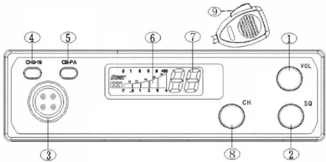
A. Front Panel
-
Off/On/Volume. Turn clockwise to turn power on and set the desired listening volume.
-
Squelch. This control is used to cut off or eliminate receiver background noise in the absence of an incoming signal. For maximum receiver sensitivity, it is desired that the control be adjusted only to the point where the receiver background noise or ambient background noise is eliminated. Adjust until the receiver noise disappears. This will require the incoming signal to be slightly stronger than the average receiver noise. Further clockwise rotation will increase the threshold level which a signal must overcome in order to be heard. Only strong signals will be heard at a maximum clockwise setting.
-
Microphone Connector. This front mounted, screw-on connector allows for convenient removal of the microphone plug when storage is required. The microphone MUST be connected to the unit at all times when in use, for proper operation. The screw-on connection enhances the life of the microphone cord as well.
-
Channel 9/Normal Switch. Used for instant selection of emergency channel 9 (CH.9 position). In NOR position, all 40 CB channels are selected by the UP/DOWN CHANNEL BUTTONS.
-
CB/PA Switch. Selects mode of operation. In the CB position, the PA function is disabled and the unit will transmit and receive on the selected channel. The PA function should not be used unless a PA speaker is connected.
-
S-RF/Power Meter. Shows relative transmitter RF output power and input signal strength when receiving. The five LED (Light Emitting Diode) segments glow to indicate receive or transmit activity.
-
TX Indicator. This indicator will light red when in the transmit mode.
-
Channel Display. The selected operating channel will be displayed here.
-
Channel Selector Switch. When turned, this knob is used to select any one of the forty citizens band channels desired.
For a “RAPID” change of channels, depress and hold the desired button (up and down). This allows all 40 channels to be covered in about 6 seconds.
Other operation Features
•Automatic Noise Limiter. This is a non-switchable feature that is always on to reduce background noise.
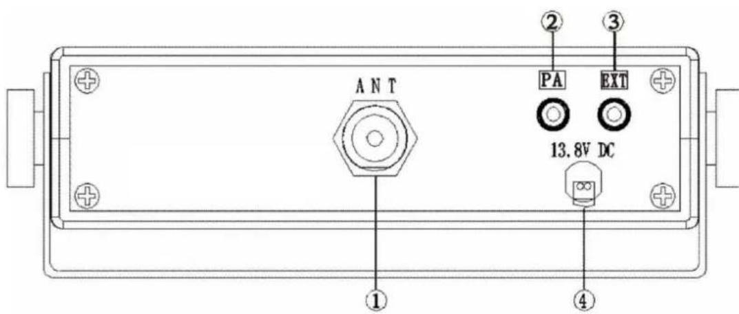
C. Rear Panel
-
ANTENNA CONNECTOR: This SO-239 connector permits connection of the transmission line cable male connector to the transceiver.
-
PUBLIC ADDRESS: An external 8-ohm 4.0 watt PA speaker may be connected to the PA Speaker Jack when this unit is used as a public address system. The speaker should be directed away from the microphone to prevent acoustic feed-back. Physical separation or isolation of the microphone and speaker must be employed when operating the PA at
high output levels.
-
EXTERNAL SPEAKER: The External Speaker Jack is used for remote receiver monitoring. The external speaker should have 8 ohms impedance and be rated to handle at least 4.0 watts. When the external speaker is plugged in, the internal speaker is automatically disconnected.
-
POWER: These wires supply power to the CB radio. See page 5 for installation.
Operating Procedure to Receive
-
Be sure that the power, antenna and microphone are properly connected before proceeding further. The CB/PA switch should be in the CB mode. The Channel 9/NOR Switch should be in the NOR mode.
-
Turn the radio ON by rotating the VOLUME CONTROL clockwise.
-
Rotate SQUELCH CONTROL counterclockwise until incoming signal is heard.
-
Turn the CHANNEL SELECTOR KNOB to select the desired operating channel.
-
Set the VOLUME CONTROL to a comfortable listening level.
Listen to the background noise from the speaker. Turn the SQUELCH CONTROL slowly clockwise until the noise JUST disappears (no signal should be present). Leave the control at this setting. The squelch is now properly adjusted. The receiver will remain quiet until a signal is actually received. Do not advance the control too far, or some of the weaker signals will not be heard.
Operating Procedure to Transmit
-
Select the desired channel.
-
Press-to-Talk Switch. The receiver and transmitter are controlled by the press-to-talk switch on the microphone. Press the switch and the transmitter is activated; release switch to receive. When transmitting, (on a clear channel), hold the microphone two inches from the mouth and speak in a clearly normal voice.
Be sure the antenna is properly connected to the radio before transmitting. Prolonged transmitting without an antenna, or a poorly matched antenna, could cause damage to the transmitter.
Operating Procedure for Public Address
-
Connect a PA speaker to the PA jack provided on the rear panel.
-
Set the CB/PA switch to the PA position.
-
Depress the push-to-talk switch on the microphone and speak in a normal voice.
-
Adjust the volume of the PA speaker using the Volume control on the front panel.
Maintenance and Adjustable
Your CB transceiver is specifically designed for the environment encountered in mobile installations. The use of all solid state circuitry and its light weight result in high reliability. Should a failure occur, however, review the following, then if necessary replace parts only with identical parts. Do not substitute. Refer to the schematic diagram and parts list.
- Check connections to the source of power and make sure it is the 13.8 VDC required to operate your radio.
- Check the fuse in the DC power cord. The main power lead (red wire) has a 2 Amp 3 AG type fuse installed. Use only the above specified type and size fuse for maximum protection. Failure to do so will void the warranty.
- Make certain the microphone is properly plugged in.
- Make certain the antenna is properly connected and tuned for mini-mum SWR. NOTE: Supernova antennas include full instructions for tuning your antenna. If you're still in doubt about the procedure, contact the supernova dealer from whom you purchased your radio and antenna, for advice. If you hired an installer to install your radio and antenna, contact him.
If you are unable to correct the problem, refer to the WARRANTY SERVICE INSTRUCTIONS at the end of this manual for the correct procedure for warranty and post-warranty service from supernova.
Adjustment Warning
Replacement or substitution of certain parts with replacements other than those recommended by Supernova Electronics, may be a violation of the technical regulations of Part 95 of the FCC Rules, or the Type Acceptance requirements of Part 2 of said rules.
When making adjustments other than transmitter adjustments, be sure to re-read applicable portions of this instruction manual to make certain you are following correct procedure and that the radio was properly installed, etc.
A Few Rules That Should Be Obeyed
- You are not allowed to carry on a conversation with another station for more than five minutes at a time without taking a one-minute break, to give others a chance to use the channel.
- You are not allowed to blast others off the air by overpowering them with illegally amplified transmitter power, or illegally high antennas.
- You can't use CB to promote illegal activities.
- You are not allowed to use profanity.
-
You may not play music in your CB.
-
You may not use your CB to sell merchandise or professional service.
How Your CB Can Serve You
- Warn of traffic tie-ups ahead.
- Provide weather and road information.
- Provide help fast in event of emergency or breakdown.
- Suggest good spots to eat and sleep.
- Make long trips more interesting, and help keep you awake.
- Provide direct contact with your office or home.
• Make friends for you as you travel. - Provide "local information" to find your destination.
- Help law enforcement officers by reporting drunk and reckless drivers.
Use Channel 9 For Message Only
FCC give the following examples of permitted and prohibited types of communications for use on Channel 9. These are guidelines and are not intended to be all-inclusive.
Permitted:
Example Message:
| Yes | “A tornado sighted six miles north of town.” |
| No | “This is observation post number 10. No tornado Sighted.” |
| Yes | “I am out of gas on Interstate 95 at mile marker 121 |
| No | “I am out of gas in my driveway.” |
| Yes | “There is a four-car collision at Exit 10 on the Beltway, send police and ambulance.” |
| No | “Traffic is moving smoothly on the Beltway.” |
| Yes | “Base to unit 1, the Weather Bureau has just issued a thunderstorm warning. Bring the sailboat into port.” |
| No | “Attention all motorists. The Weather Bureau advises that the snow tomorrow will accumulate 4 to 6 inches.” |
| Yes | “There is a fire in the building on the corner of 6th and Main Streets.” |
| No | “This is Halloween patrol unit number 3. Everything is quiet here.” |
CITIZENS BAND 2-WAY MOBILE RADIO
MODEL OV-CB-501B Úvod
Frekvenční rozsah
natural_image
Technical line drawing of a mechanical assembly with gears and a base plate (no text or symbols)C. Zadní panel
condensator electric
Tensiune
13.8V DC negative la sol
Pierderi de current
Transmisie
AM
in mod
full
1.5A
maxim
Primire: (inceteaza, 0.115A, iesire audio full 1.0A normal)
Marime
131mm(D)×171mm(W)×44.5mm(H)
Greutate
3lbs., 4 oz (1.0Kg)
Conectarea antenei
UHF, SO-239
Semiconductoare
22 tranzistori, 17 diode, 3 circuite integrate, 3 leduri,
Contor
Indica curentul relativ la iesire si primire
TRANSMITATOR
Puterea de iesire
4 watti
Modularea
nivel inalt/jos clasa B amplitudine
Frecventa
300 pana la 3000 Hz
Iesire impedanta
50 ohms dezechilibrat
Tranzistorii protejeaza impotriva nepotrivirilor pana la 20:1
natural_image
Technical line drawing of a mechanical assembly with gears and a rectangular base (no text or symbols)C. Panoul din spate
Declaraon of Conformity
hereby we conrm above product compliance with the European directive of RTTE (1999/5/WE) :
EN 300 433-1 V1.1.3, EN 300 433-2 V1.1.2
EN 301 489-1 V1.7.1, EN 301 489-13 V1.2.1
EN 60950-1 2001
Tests made: EMCC DR, RA, EK
Cercaon by: EMCC DR, RA, EK
Registraon No. G108457A
Release date: 2011-01-13
CE0678①

- 2-ZAKRESOWE PRZENOŚNE RADIO CB PASMA OBYWATELSKIEGO
- Wprowadzenie
- Panel tylny
- PA SYSTEM
- Installation
- Location
- Mounting Connection
- CB Antennas
- Ignition Noise Interference
- Temporary Mobile Operations
- Operation
- Control and Indicators
- Other operation Features
- Rear Panel
- Operating Procedure to Receive
- Operating Procedure to Transmit
- Operating Procedure for Public Address
- Maintenance and Adjustable
- Adjustment Warning
- A Few Rules That Should Be Obeyed
- How Your CB Can Serve You
- Use Channel 9 For Message Only
- CITIZENS BAND 2-WAY MOBILE RADIO
- MODEL OV-CB-501B Úvod
- Frekvenční rozsah
- Zadní panel
- TRANSMITATOR
- Panoul din spate
- Declaraon of Conformity
Brand : Overmax
Model : CB-501B
Category : Car radio