WG51 - Ventilateur domestique Eldom - Free user manual and instructions
Find the device manual for free WG51 Eldom in PDF.


| Product Type | Domestic Fan (Stand Fan) |
| Brand | Eldom |
| Model | WG51 |
| Power Consumption | 50 W |
| Voltage Supply | 230 V ~ 50 Hz |
| Number of Fan Speeds | 3 (I, II, III) |
| Oscillation Function | Yes, with push button (L) |
| Height Adjustment | Yes, via locking ring (I) |
| Assembly | Required, with included parts (base, arm, shank, meshes, airscrew, nuts) |
| Safety Features | Do not immerse in water; do not use near curtains; do not insert objects; do not spray insect killers; do not cover; do not use in high humidity or explosive atmospheres. |
| Cleaning Instructions | Unplug before cleaning; do not use abrasive cleaners; do not immerse in water. |
| Intended Use | Household use only, not for professional purposes |
| Warranty | Valid for domestic use; expires if misused |
| Environmental Disposal | Recyclable materials; dispose at appropriate electronic waste collection point |
| Manual Availability | Free PDF download on notice-facile.com |
| Power Cord | Fixed; if damaged, replace only by authorized service center |
| Repairs | Only by authorized service centers; list available on www.eldom.eu |
Frequently Asked Questions - WG51 Eldom
User questions about WG51 Eldom
0 question about this device. Answer the ones you know or ask your own.
Ask a new question about this device
Download the instructions for your Ventilateur domestique in PDF format for free! Find your manual WG51 - Eldom and take your electronic device back in hand. On this page are published all the documents necessary for the use of your device. WG51 by Eldom.
USER MANUAL WG51 Eldom
natural_image
Black outdoor fan with mesh grille and four legs, mounted on a stand (no visible text or symbols)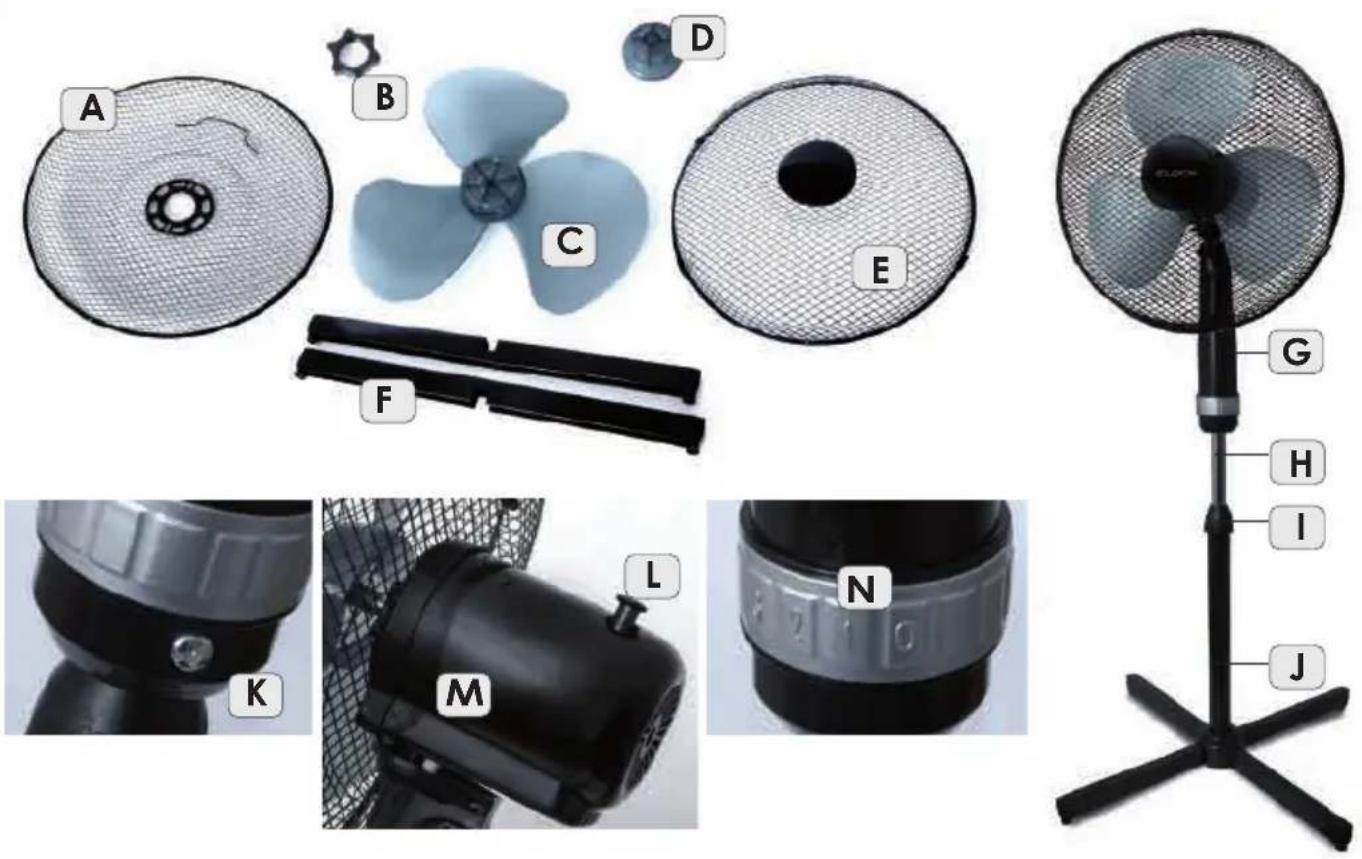
natural_image
Close-up of two black metal X-shaped metal components with bolt holes (no text or symbols visible)fot. 01
natural_image
Close-up of a black mechanical joint with four bolts and mounting brackets (no text or symbols visible)fot. 02
natural_image
Close-up of a black mechanical component with four arms, no visible text or symbolsfot. 03
OPIS OGÓLNY
natural_image
Close-up of a black mechanical component with a metallic knob and a circular button labeled 'K' (no text or symbols on the object itself)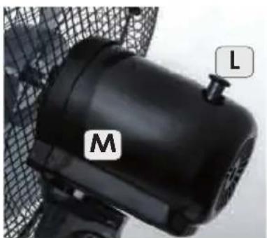
natural_image
Close-up of a black industrial fan with labeled components (M and L), no visible text or symbols beyond labels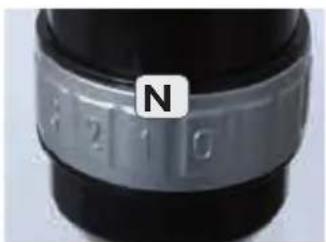
natural_image
Close-up of a camera lens with a metallic strap and 'N' label (no additional text or symbols)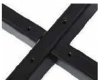
natural_image
Close-up of two black metal bars crossed with a white X symbol (no text or markings visible)fig. 01
natural_image
Close-up of a black mechanical joint with four bolts and mounting flanges (no text or symbols visible)fig. 02
natural_image
Close-up of a black four-petal screw or knob with no visible text or symbolsfig. 03
GENERAL DESCRIPTION
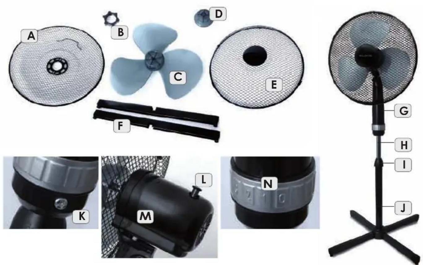
A. Protective mesh - rear
B. Nut
C. Airscrew
D. Nut securing the airscrew
E. Protective mesh - front
F. base feet
G. ArmH. Shank
1. height regulation locki
J. Base
K. Arm assembly lock
L. Oscillation switch
M. Body
N. Switch and gears: I, II and III
TECHNICAL DATA
- power: 50W
- voltage supply: 230V \~ 50Hz
ASSEMBLY AND THE APPLIANCE OPERATION
Before the first use, unpack the unit and put particular elements together.
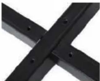
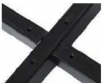
- unscrew screws from the base feet (F) and couple the feet of the base together (cross), fig. 01
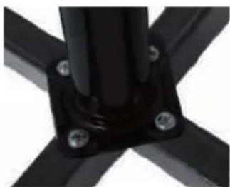
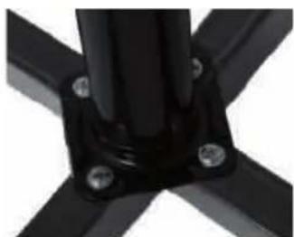
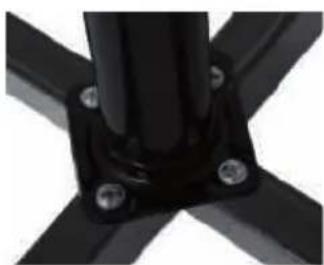
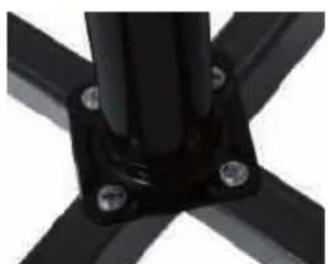
- using the screws couple the feet (F) with the collar of the base (J), fig. 02
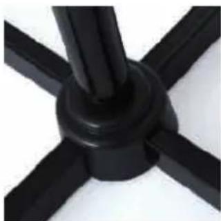
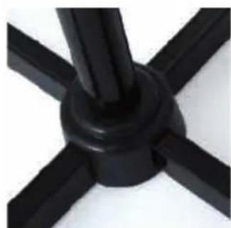
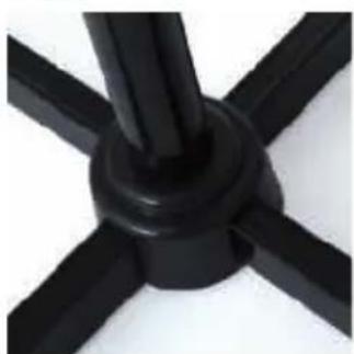
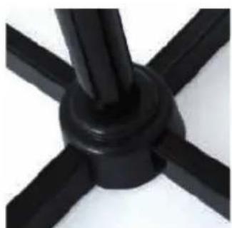
- remove the shield from the base (J), fig. 03
- couple the arm (G) with the body (M) together with the shank (H). To do the above, slide the arm into the shank (if it is necessary loosen the lock (K)) and lock it by tightening the lock (K)
-unscrew the nuts (B,D) from the body's shaft (M) - fix the rear protective mesh (A). Adjust the holes in the mesh to the clamps of the body, fig. 04
- fix the nut (B), twisting it clockwise, fig. 5
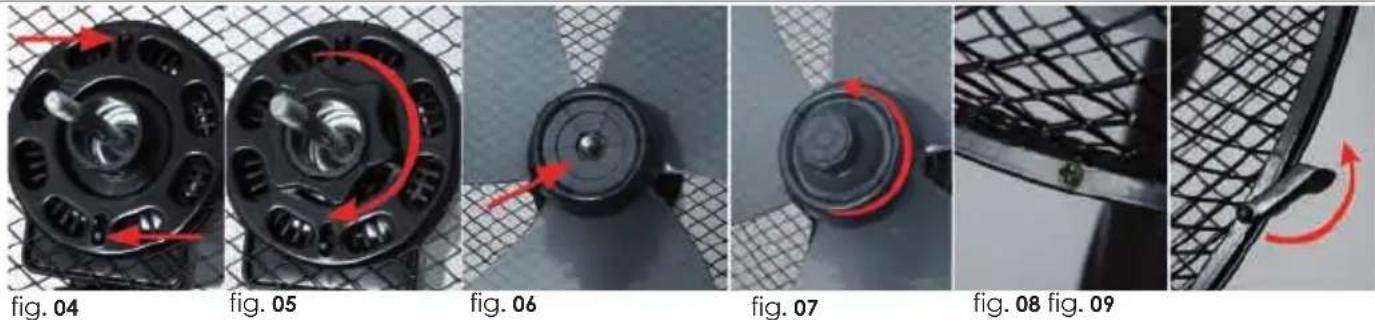
- slide the airscrew (C) on the pin, fig. 6
- secure the airscrew with the nut (D), twisting it counterclockwise, fig. 7
- fix the front protective mesh (E). Couple both meshes in the bottom part due to a bolt, protect by clamps, fig. 8 and 9
- put the unit on a stable and even surface
- set the height. Loosen the ring (I), slide into shaft into required height. Lock by twisting the ring (I).
Select the fan rotation speed (position "1", "2" or "3") with the switch (N). After turning the knob into the "0" position, the appliance is turned off.
Undependably on selected speed, it is possible to select the circulation option after pressing the button (L). To switch the above function off, pull the button out (L).
CLEANING AND MAINTENANCE ACTIVITIES
- unplug the unit before cleaning
- do not merge the unit in water
- to not use abrasive or other damaging cleaning agents
SAFETY OPERATION INSTRUCTIONS
- read the manual carefully before use
- please, do not plug too many appliances to a single electric circuit
- the unit is designed to operate at a household
- place the unit on a flat and dry surface
- do not inert fingers or any other objects into the inlet and outlet holes
- do not place the unit near cushions or curtains
- working fan must be always supervised, especially, when there are children nearby
-leaving a room where a fan operates, switch it off - do not spray any insect killers or similar agents near the operating fan
- do not use the appliance under high temperature (exceeding 40°C), in localizations where the humidity rate is high (e.g. bathroom) and localizations where explosive atmosphere occurs
- before switching the unit on make sure all its elements are correctly fixed. Under no circumstances one may switch the unit on before it has been completely assembled!
- do not cover the protective mesh
- do not use the appliance as a hanger
- in case the power cord is damaged it must be replaced by the manufacturer's authorized service center
- The unit may be repaired by a manufacturer's authorized service center only (list of the centers attached and available on the website: www.eldom.eu). All modifications or use of non-original spare parts or any other elements is prohibited and makes use of the unit hazardous.
- Eldom Sp. z o. o. shall not be liable for potential damages arising from improper use of the unit.
ENVIRONMENT PROTECTION
- the unit is made of materials which may be reused or re-cycled
- they must be provided to a relevant point which specializes in collecting and recycling of electric and electronic appliances
GUARANTEE
- the unit is intended to be used in a household.
- it must not be used for professional purposes,
- the guarantee expires in case of improper service
natural_image
Close-up of a black X-shaped metal joint with bolt holes (no text or symbols)fot. 01
natural_image
Close-up of a black mechanical joint with four bolts and mounting brackets (no text or symbols visible)fot. 02
natural_image
Close-up of a black four-petal screw head with no visible text or symbolsfot. 03
POPIS
natural_image
Close-up of a black mechanical component with red directional arrows indicating motion or force (no text or symbols visible)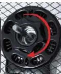
natural_image
Close-up of a black mechanical component with a red spiral arrow indicating rotational motion (no text or symbols)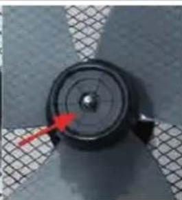
natural_image
Close-up of a mechanical component with a red arrow pointing to a circular feature, set against a textured gray background (no text or symbols visible)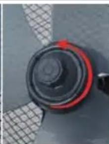
natural_image
Close-up of a black circular mechanical component with red and white bands, no visible text or symbols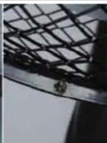
natural_image
Close-up of a metal mesh structure with a small metallic bolt attached (no text or symbols visible)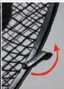
natural_image
Close-up of a mesh metal panel with a red curved arrow indicating rotation (no text or symbols)fot. 04
fot. 05
fot. 06
fot. 07
fot. 08 fot. 09
- vrtuli (C) nasunout na trn, fot. 6
natural_image
Close-up of two black metal bars crossed with a white X symbol (no text or markings visible)Bild 01
natural_image
Close-up of a black mechanical joint with four bolts and mounting flanges (no text or symbols visible)Bild 02
TECHNISCHE DATEN
natural_image
Close-up of a black mechanical component with four arms and central hub (no text or symbols visible)Bild 03
natural_image
Close-up of two black metal beams with cross-shaped cutouts (no text or symbols visible)фото 01
natural_image
Close-up of a black metal bracket with four bolt holes and mounting flanges (no text or symbols visible)ФОТО 02
natural_image
Close-up of a black four-blade mechanical component with no visible text or symbolsфото 03
ОБЩАЯ ИНФОРМАЦИЯ


Brand : Eldom
Model : WG51
Category : Ventilateur domestique