 U — Cooker — Mode d'emploi PDF")
I5GMH5AG(W) U - Cooker INDESIT - Free user manual and instructions
Find the device manual for free I5GMH5AG(W) U INDESIT in PDF.

| Product Type | Freestanding gas cooker with electric oven |
| Brand | Indesit |
| Model | I5GMH5AG(W) U |
| Dimensions (H x W x D) | 340 x 391 x 424 mm |
| Oven Volume | 57 L |
| Lower Compartment Dimensions | 420 x 230 x 440 mm |
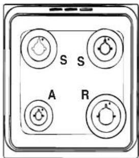
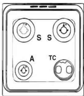
| Hob Burner Types | Fast (R), Semi Fast (S), Auxiliary (A), Triple Crown (TC) |
| Burner Powers (Nominal) | Fast: 3.40 kW, Semi Fast: 2.20 kW, Auxiliary: 1.30 kW, Triple Crown: 3.25 kW |
| Oven Heating Modes | Baking, Convection, Fan Assisted, Grill, Double Grill, Fan Assisted Double Grill, Defrosting, Bottom Ventilated, Bottom, Pizza |
| Oven Temperature Range | 50°C to 250°C (max) |
| Safety Features | Flame failure safety device on hob, anti-tilt safety chain, oven door stop system |
| Cleaning | Steam-assisted oven cleaning, removable inner door glass for easy cleaning |
| Oven Light | 25 W, E14 cap, replaceable |
| Voltage / Frequency | 230 V / 50-60 Hz |
| Gas Connection | Flexible rubber or steel hose, adaptable to LPG or natural gas |
| Adjustable Feet | Yes (4 feet) |
| Hob Glass Cover | Removable, for easy cleaning (on selected models) |
| Rotisserie | Available (on selected models) |
| Automatic Timer/Programmer | Electronic timer with delayed cooking (on selected models) |
| Energy Label | EU Energy Label compliant (details on data plate) |
Frequently Asked Questions - I5GMH5AG(W) U INDESIT
User questions about I5GMH5AG(W) U INDESIT
0 question about this device. Answer the ones you know or ask your own.
Ask a new question about this device
Download the instructions for your Cooker in PDF format for free! Find your manual I5GMH5AG(W) U - INDESIT and take your electronic device back in hand. On this page are published all the documents necessary for the use of your device. I5GMH5AG(W) U by INDESIT.
USER MANUAL I5GMH5AG(W) U INDESIT
Operating Instructions COOKER AND OVEN
Contents
Operating Instructions,1
WARNING,2
Description of the appliance-Overall view,5
Description of the appliance-Control Panel,6
Installation,7
Start-up and use,12
Cooking modes,13
Precautions and tips,19
Care and maintenance,20
Assistance,20
PL
Polski
Instrukcja obsługi
KUCHENKA I PIEKARNIK
Spis treści
WARNING: The appliance and its accessible parts become hot during use.
Care should be taken to avoid touching heating elements.
Children less than 8 years of age shall be kept away unless continuously supervised.
This appliance can be used by children aged from 8 years and above and persons with reduced physical, sensory or mental capabilities or lack of experience and knowledge if they have been given supervision or instruction concerning use of the appliance in a safe way and understand the hazards involved. Children shall not play with the appliance. Cleaning and user maintenance shall not be made by children without supervision.
WARNING: Unattended cooking on a hob with fat or oil can be dangerous and may result in fire.
NEVER try to extinguish a fire with water, but switch off the appliance and then cover flame e.g. with a lid or a fire blanket.
Do not use harsh abrasive cleaners or sharp metal scrapers to clean the oven door glass since they can scratch the surface, which may result in shattering of the glass.
The internal surfaces of the compartment (where present) may become hot.
CAUTION: the use of inappropriate hob guards can cause accidents.
Never use steam cleaners or pressure cleaners on the appliance.
Remove any liquid from the lid before opening it.
Do not close the glass cover (if present) when the gas burners or electric hotplates are still hot.
WARNING: Ensure that the appliance is switched off before replacing the lamp to avoid the possibility of electric shock.
! When you place the rack inside, make sure that the stop is directed upwards and in the back of the cavity.
PL
UWAGAUWAGA
Description of the appliance Overall view
1.Hob burner
2.Hob Grid
3. Control panel
4.Sliding grill rack
5.DRIPPING pan
6..Adjustable foot
7. Containment surface for spills
8. GUIDE RAILS for the sliding racks
9.position 5
10.position 4
11.position 3
12.position 2
13.position 1
14.Glass Cover *
*Available only on certain models
PL
Description of the appliance Control panel
1.TIMER knob*
2. Electronic cooking programmer*
3.TIMER button*
4.COOKING TIME button*
5.COOKING END TIME button*
6.THERMOSTAT knob
7. SELECTOR knob
8.THERMOSTAT indicator light
9.Hob BURNER control knob
*Available only on certain models
PL
! Before operating your new appliance please read this instruction booklet carefully. It contains important information concerning the safe installation and operation of the appliance.
! Please keep these operating instructions for future reference. Make sure that the instructions are kept with the appliance if it is sold, given away or moved.
! The appliance must be installed by a qualified professional according to the instructions provided.
! Any necessary adjustment or maintenance must be performed after the cooker has been disconnected from the electricity supply.
Room ventilation
The appliance may only be installed in permanently-ventilated rooms, according to current national legislation. The room in which the appliance is installed must be ventilated adequately so as to provide as much air as is needed by the normal gas combustion process (the flow of air must not be lower than 2 m^3/h per kW of installed power).
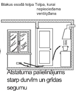
The air inlets, protected by grilles, should have a duct with an inner cross section of at least 100 cm^2 and should be positioned so that they are not liable to even partial obstruction (see figure A).
These inlets should be enlarged by 100% - with a minimum of 200 cm ^2 - whenever the surface of the hob is not equipped with a flame failure safety device. When the flow of air is provided in an indirect manner from adjacent rooms (see figure B), provided that these are not communal parts of a building, areas with increased fire hazards or bedrooms, the inlets should be fitted with a ventilation duct leading outside as described above.
A
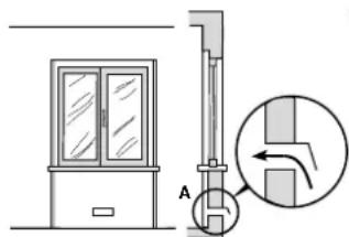
Ventilation opening for
comburent air
B
Adjacent room Room requiring ventilation
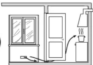
natural_image
Simple line drawing of a room with doors, a chimney, and a steam pipe (no text or symbols)Increase in the gap between the door and the flooring
! After prolonged use of the appliance, it is advisable to open a window or increase the speed of any fans used.
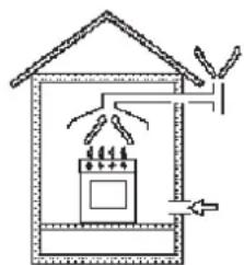
Disposing of combustion fumes
The disposal of combustion fumes should be guaranteed using a hood connected to a safe and efficient natural suction chimney, or using an electric fan that begins to operate automatically every time the appliance is switched on (see figure).
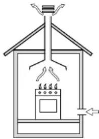
natural_image
Simple line drawing of a house interior with a stove, roof, and air duct (no text or symbols)Fumes channelled straight outside
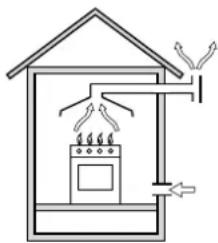
natural_image
Simple line drawing of a house with a stove, roof, and electrical connections (no text or symbols)Fumes channelled through a chimney or a branched flue system (reserved for cooking appliances)
! The liquefied petroleum gases are heavier than air and collect by the floor, therefore all rooms containing LPG cylinders must have openings leading outside so that any leaked gas can escape easily.
LPG cylinders, therefore, whether partially or completely full, must not be installed or stored in rooms or storage areas that are below ground level (cellars, etc.). Only the cylinder being used should be stored in the room; this should also be kept well away from sources of heat (ovens, chimneys, stoves) that may cause the temperature of the cylinder to rise above 50^ C.
Positioning and levelling
! It is possible to install the appliance alongside cupboards whose height does not exceed that of the hob surface.
! Make sure that the wall in contact with the back of the appliance is made from a non-flammable, heat-resistant material (T 90°C).
To install the appliance correctly:
- Place it in the kitchen, dining room or the bed-sit (not in the bathroom).
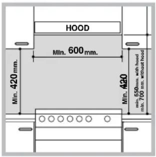
- If the top of the hob is higher than the cupboards, the appliance must be installed at least 200 mm away from them.
- If the cooker is installed underneath a wall cabinet, there must be a minimum distance of 420 mm between this cabinet and the top of the hob.
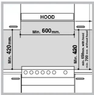
- If the cooker is installed underneath a wall cabinet, there must be a minimum distance of 420mm between this cabinet and the top of the hob.
This distance should be increased to 700 mm if the wall cabinets are flammable (see figure).
- Do not position blinds behind the cooker or less than 200 mm away from its sides.
- Any hoods must be installed according to the instructions listed in the relevant operating manual.
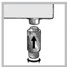
Levelling
natural_image
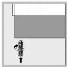
Pure diagram of a mechanical or electrical component with no visible text, numbers, or symbolsIf it is necessary to level the appliance, screw the adjustable feet into the places provided on each corner of the base of the cooker (see figure).
natural_image
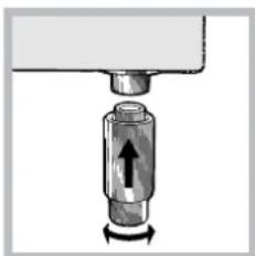
Mechanical component diagram showing a cylindrical assembly with an arrow indicating force direction (no text or symbols)The legs* fit into the slots on the underside of the base of the cooker.
Electrical connection
Install a standardised plug corresponding to the load indicated on the appliance data plate (see Technical data table).
The appliance must be directly connected to the mains using an omnipolar circuit-breaker with a minimum contact opening of 3 mm installed between the appliance and the mains. The circuit-breaker must be suitable for the charge indicated and must comply with NFC 15-100 regulations (the earthing wire must not be interrupted by the circuit-breaker). The supply cable must be positioned so that it does not come into contact with temperatures higher than 50°C at any point.
Before connecting the appliance to the power supply, make sure that:
- The appliance is earthed and the plug is compliant with the law.
-
The socket can withstand the maximum power of the appliance, which is indicated by the data plate.
-
The voltage is in the range between the values indicated on the data plate.
- The socket is compatible with the plug of the appliance. If the socket is incompatible with the plug, ask an authorised technician to replace it. Do not use extension cords or multiple sockets.
! Once the appliance has been installed, the power supply cable and the electrical socket must be easily accessible.
! The cable must not be bent or compressed.
! The cable must be checked regularly and replaced by authorised technicians only.
! The manufacturer declines any liability should these safety measures not be observed.
Gas connection
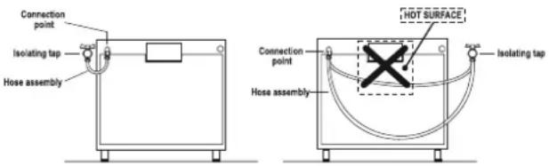
Connection to the gas network or to the gas cylinder may be carried out using a flexible rubber or steel hose, in accordance with current national legislation and after making sure that the appliance is suited to the type of gas with which it will be supplied (see the rating sticker on the cover: if this is not the case see below). When using liquid gas from a cylinder, install a pressure regulator which complies with current national regulations. To make connection easier, the gas supply may be turned sideways*: reverse the position of the hose holder with that of the cap and replace the gasket that is supplied with the appliance.
! Check that the pressure of the gas supply is consistent with the values indicated in the Table of burner and nozzle specifications (see below). This will ensure the safe operation and durability of your appliance while maintaining efficient energy consumption.
Gas connection using a flexible rubber hose
Make sure that the hose complies with current national legislation. The internal diameter of the hose must measure: 8 mm for liquid gas supply; 13 mm for methane gas supply.
Once the connection has been performed, make sure that the hose:
- Does not come into contact with any parts that reach temperatures of over 50^ C.
- Is not subject to any pulling or twisting forces and that it is not kinked or bent.
-
Does not come into contact with blades, sharp corners or moving parts and that it is not compressed.
-
Is easy to inspect along its whole length so that its condition may be checked.
• Is shorter than 1500 mm. - Fits firmly into place at both ends, where it will be fixed using clamps that comply with current regulations.
! If one or more of these conditions is not fulfilled or if the cooker must be installed according to the conditions listed for class 2 - subclass 1 appliances (installed between two cupboards), the flexible steel hose must be used instead (see below).
Connecting a flexible jointless stainless steel pipe to a threaded attachment
Make sure that the hose and gaskets comply with current national legislation.
To begin using the hose, remove the hose holder on the appliance (the gas supply inlet on the appliance is a cylindrical threaded 1/2 gas male attachment).
! Perform the connection in such a way that the hose length does not exceed a maximum of 2 metres, making sure that the hose is not compressed and does not come into contact with moving parts.
Checking the tightness of the connection
When the installation process is complete, check the hose fittings for leaks using a soapy solution. Never use a flame.
Adapting to different types of gas
It is possible to adapt the appliance to a type of gas other than the default type (this is indicated on the rating label on the cover).
Adapting the hob
Replacing the nozzles for the hob burners:
- Remove the hob grids and slide the burners off their seats.
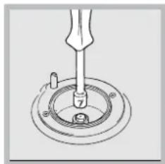
natural_image
Technical line drawing of a mechanical assembly with a tool inserted into a circular component (no text or symbols)-
Unscrew the nozzles using a 7 mm socket spanner (see figure), and replace them with nozzles suited to the new type of gas (see Burner and nozzle specifications table).
-
Replace all the components by following the above
instructions in reverse.
Adjusting the hob burners' minimum setting:
- Turn the tap to the minimum position.
- Remove the knob and adjust the regulatory screw, which is positioned inside or next to the tap pin, until the flame is small but steady.
! If the appliance is connected to a liquid gas supply, the regulatory screw must be fastened as tightly as possible. - While the burner is alight, quickly change the position of the knob from minimum to maximum and vice versa several times, checking that the flame is not extinguished.
! The hob burners do not require primary air adjustment.
! After adjusting the appliance so it may be used with a different type of gas, replace the old rating label with a new one that corresponds to the new type of gas (these labels are available from Authorised Technical Assistance Centres).
! Should the gas pressure used be different (or vary slightly) from the recommended pressure, a suitable pressure regulator must be fitted to the inlet hose in accordance with current national regulations relating to "regulators for channelled gas".
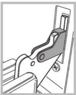
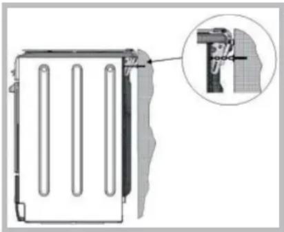
Safety Chain
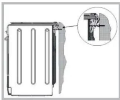
natural_image
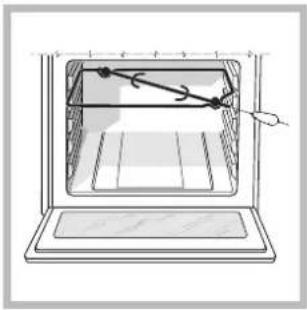
Technical diagram of a mechanical component with an inset close-up showing a detail (no text or symbols)! In order to prevent accidental tipping of the appliance, for example by a child climbing onto the oven door, the supplied safety chain MUST be installed!
The cooker is fitted with a safety chain to be fixed by means of a screw (not supplied with the cooker) to the wall behind the appliance, at the same height as the chain is attached to the appliance.
Choose the screw and the screw anchor according to the type of material of the wall behind the appliance. If the head of the screw has a diameter smaller than 9mm, a washer should be used. Concrete wall requires the screw of at least 8mm of diameter, and 60mm of length.
Ensure that the chain is fixed to the rear wall of the cooker and to the wall, as shown in figure, so that after installation it is tensioned and parallel to the ground level.
Replacing the Triple ring burner nozzles \*
- Remove the pan supports and lift the burners out of their housing. The burner consists of two separate parts (see pictures).
- Unscrew the nozzles using a 7 mm socket spanner. Replace the nozzles with models that are configured for use with the new type of gas (see Table 1). The two nozzles have the same hole diameter.
- Replace all the components by completing the above operations in reverse order.
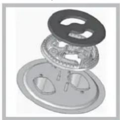
natural_image
Exploded view diagram of a mechanical assembly (no text or symbols visible)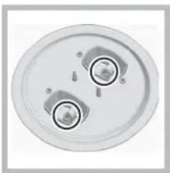
natural_image
Top-down view of a circular mechanical component with two central holes and mounting holes (no text or symbols visible)- Adjusting the burners' primary air :
Does not require adjusting.
- Setting the burners to minimum:
- Turn the tap to the low flame position.
- Remove the knob and adjust the adjustment screw, which is positioned in or next to the tap pin, until the flame is small but steady.
setting, while the burner is alight, quickly change
the position of the knob from minimum to maximum and vice versa several times, checking that the flame does not go out. (thermocouple) fitted. If the device fails to work
when the burners are set to the low flame setting, increase this low flame setting using the adjusting screw.
seals on the by-passes using sealing wax
- Once the adjustment has been made, replace the
! If the appliance is connected to liquid gas, the regulation screw must be fastened as tightly as possible.
! Once this procedure is finished, replace the old rating sticker with one indicating the new type of gas used. Stickers are available from any of our Service Centres.
! Should the gas pressure used be different (or vary slightly) from the recommended pressure, a suitable pressure regulator must be fitted to the inlet pipe (in order to comply with current national regulations).
I5GMH6AG.1 U
I5GMH6AG U
I5GMH2AG U
I5GMH5AG U
I5GMHA U
I5GMH1A U
I5GMH5AG U
I5GMH6AG U
I5TMH6AG U I5TMH5AG.1 U
Table of burner and nozzle specifications
| TABLE OF CHARACTERISTSICS | (with drawn guide rails) | |
| Dimensions | 'width 391 mmheight 340 mmdepth 424 mm | 'width 410 mmheight 340 mmdepth 424 mm |
| Volume | I5GMH2AG UISGMH5AG UI5GMHA U 57II5GMH1A U I5GMH5AG UI5GMH6AG U | I5TMH6AG UI5GMH6AG.1 UI5GMH6AG UI5TMH5AG.1 U |
| Dimensions of the lower compartment | width 42 cmheight 23 cmdepth 44 cm | |
| Burners | may be adapted for use with any type of gas shown on the data plate, which is located inside the flap or, after the oven compartment has been opened, on the left-hand wall inside the oven. | |
| Voltage and frequency | see data plate | |
| ENERGY LABELand ECODESIGN | Regulation (EU) No 65/2014 supplementing Directive 2010/30/EU.Regulation (EU) No 66/2014 implementing Directive 2009/125/EC.Standard EN 60350-1Standard EN 50564.Standard EN 30-2-1Energy consumption for Natural convection – heating mode: ____Convection;Declared energy consumption for Forced convection Class – heating mode: Baking | |
| This appliance conforms to the following European Economic Community directives: 2006/95/EC dated 12/12/06 (Low Voltage) and subsequent amendments - 2004/108/EC dated 15/12/04 (Electromagnetic Compatibility) and subsequent amendments - 93/68/EEC dated 22/07/93 and subsequent amendments.2002/96/EC2009/142 of 30/11/09 (Gas)1275/2008 (Stand-by/ Off mode) | ||
Data plate, is located inside the flap or, after the oven compartment has been opened, on the left-hand wall inside the oven.
| Table 1 | G30 (GPB-B) | G20 (GZ50) | |||||||
| Burner Diameter | (mm) | Thermal power kW (p.c.s.*) Reduc. | Thermal power kW (p.c.s.*) Nominal | By-pass 1/100 (mm) | Nozzle 1/100 (mm) | Flow* g/h | Thermal power kW (p.c.s.*) Nominal | Nozzle 1/100 (mm) | Flow* l/h |
| Fast (Large)(R) | 100 | 0,70 | 3,40 | 41 | 87 | 247 | 3,00 | 128 | 286 |
| Semi Fast (Medium) (S) | 75 | 0,40 | 2,20 | 30 | 70 | 160 | 1,90 | 104 | 181 |
| Auxiliary (Small) (A) | 51 | 0,40 | 1,30 | 30 | 52 | 95 | 1,00 | 76 | 95 |
| Tripple Crown (TC) | 130 | 3.25 | 1.5 | 63 | 2x65 | 262 | 3,25 | 2x99 | 309 |
| Supply Pressures | Minimum (mbar) Nominal (mbar) Maximum (mbar) | 29 37 44 | 16 20 25 | ||||||
* A 15°C e 1013 mbar-dry gas
G2.350 (GZ35) p.c.s. 27.20 MJ/m
G20 (GZ50) p.c.s. 37,78 MJ/m
G30 (GPB-B) p.c.s. 49,47 MJ/Kg
Start-up and use
GB
Using the hob
Lighting the burners
For each BURNER knob there is a full ring showing the strength of the flame for the relevant burner.
To light one of the burners on the hob:
- Bring a flame or gas lighter close to the burner.
- Press the BURNER knob and turn it in an anticlockwise direction so that it is pointing to the maximum flame setting ⬆.
- Adjust the intensity of the flame to the desired level by turning the BURNER knob in an anticlockwise direction. This may be the minimum setting ▶, the maximum setting ▶ or any position in between the two.
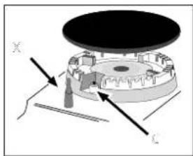
If the appliance is fitted with an electronic lighting
natural_image
Mechanical assembly diagram showing a rotating disk with labeled axes X and C (no text or symbols beyond labels)device* (C), press the BURNER knob and turn it in an anticlockwise direction, towards the minimum flame setting, until the burner is lit. The burner may be extinguished when the knob is released. If this occurs,
repeat the operation, holding the knob down for a longer period of time.
f the appliance is equipped with a flame failure safety device (X), press and hold the BURNER knob for approximately 3-7 seconds to keep the flame alight and to activate the device.
! If the flame is accidentally extinguished, switch off the burner and wait for at least 1 minute before attempting to relight it.
To switch the burner off, turn the knob until it reaches the stop position •.
WARNING! The glass lid can break in if it is heated up. Turn off all the burners and the electric plates before closing the lid.
Practical advice on using the burners
For the burners to work in the most efficient way possible and to save on the amount of gas consumed, it is recommended that only pans that have a lid and a flat base are used. They should also be suited to the size of the burner:
| Burner ř Cookware diameter (cm) | |
| Fast (R) 2HG)26 | |
| Semi Fast (S) 16 - 20 | |
| Auxiliary (A) 10 - 14 | |
To identify the type of burner, please refer to the diagrams contained in the "Burner and nozzle specifications".
Using the oven
! The first time you use your appliance, heat the empty oven with its door closed at its maximum temperature for at least half an hour. Ensure that the room is well ventilated before switching the oven off and opening the oven door. The appliance may emit a slightly unpleasant odour caused by protective substances used during the manufacturing process burning away.
! Before operating the product, remove all plastic film from the sides of the appliance.
! Never put objects directly on the bottom of the oven; this will avoid the enamel coating being damaged.
! Should the appliance be equipped with an electronic programmer*, to use the electric oven, just press buttons and at the same time (the symbol will appear on the display) before selecting the desired cooking function.
-
Select the desired cooking mode by turning the SELECTOR knob.
-
Select the recommended temperature for the cooking mode or the desired temperature by turning the THERMOSTAT knob.
A list detailing cooking modes and suggested cooking temperatures can be found in the relevant table (see Oven cooking advice table).
During cooking it is always possible to:
- Change the cooking mode by turning the SELECTOR knob.
- Change the temperature by turning the THERMOSTAT knob.
- Stop cooking by turning the SELECTOR knob to the "0" position.
! Always place cookware on the rack(s) provided.
THERMOSTAT indicator light
When this is illuminated, the oven is generating heat. It switches off when the inside of the oven reaches the selected temperature. At this point the light illuminates and switches off alternately, indicating that the thermostat is working and is maintaining the temperature at a constant level.
Oven light
This is switched on by turning the SELECTOR knob to any position other than "0". It remains lit as long as the oven is operating. By selecting with the knob, the light is switched on without any of the heating elements being activated.
Timer\*
To activate the Timer proceed as follows:
- Turn the TIMER knob in a clockwise direction for almost one complete revolution to set the buzzer.
- Turn the TIMER knob in an anticlockwise direction to set the desired length of time.
Cooking modes

BAKING mode
Temperature: any temperature between 50^ C and Max. The rear heating element and the fan come on, guaranteeing delicate heat distributed uniformly throughout the oven.
This mode is ideal for baking and cooking delicate foods - especially cakes that need to rise - and for the preparation of certain tartlets on 3 shelves at the same time. Here are a few examples: cream puffs, sweet and savoury biscuits, savoury puffs, Swiss rolls and small portions of vegetables au gratin, etc.....

CONVECTION mode
Temperature: any temperature between 50°C and Max. On this setting, the top and bottom heating elements come on. This is the classic, traditional type of oven which has been perfected, with exceptional heat distribution and reduced energy consumption. The convection oven is still unequalled when it comes to cooking dishes made up of several ingredients, e.g. cabbage with ribs, Spanish style cod, Ancona style stockfish, tender veal strips with rice, etc. Excellent results are achieved when preparing veal or beef-based dishes as well (braised meats, stew, goulash, wild game, ham etc.) which need to cook slowly and require basting or the addition of liquid. It nonetheless remains the best system for baking cakes as well as
fruit and cooking using covered casserole dishes for oven baking. When cooking in convection mode, only use one dripping pan or cooking rack at a time, otherwise the heat distribution will be uneven. Using the different rack heights available, you can balance the amount of heat between the top and the bottom of the oven. Select from among the various rack heights based on whether the dish needs more or less heat from the top.

FAN ASSISTED mode
Temperature: any temperature between 50^ C and Max. The heating elements, as well as the fan, will come on. Since the heat remains constant and uniform throughout the oven, the air cooks and browns food uniformly over its entire surface. With this mode, you can also cook various dishes at the same time, as long as their respective cooking temperatures are the same. A maximum of 2 racks can be used at the same time, following the instructions in the section entitled: "Cooking On More Than One Rack".
This fan assisted mode is particularly recommended for dishes requiring a gratin finish or for those requiring considerably prolonged cooking times, such as for example: lasagne, pasta bakes, roast chicken and potatoes, etc... Moreover, the excellent heat distribution makes it possible to use lower temperatures when cooking roasts. This results in less loss of juices, meat which is more tender and a decrease in the loss of weight for the roast. The fan assisted mode is especially suited for cooking fish, which can be prepared with the addition of a limited amount of condiments, thus maintaining their flavour and appearance.
Desserts: the fan assisted mode is also perfect for baking leavened cakes.
Moreover, this mode can also be used to thaw quickly white or red meat and bread by setting the temperature to 80 °C . To thaw more delicate foods, set the thermostat to 60 °C or use only the cold air circulation feature by setting the thermostat to 0 °C .

OVEN VON mode
The central part of the top heating element is switched on. The high and direct temperature of the grill is recommended for food that requires a high surface temperature (veal and beef steaks, fillet steak and entrecôte). This cooking mode uses a limited amount of energy and is ideal for grilling small dishes. Place the food in the centre of the rack, as it will not be cooked properly if it is placed in the corners.

PIZZA modemode
The circular heating elements and the elements at the bottom of the oven are switched on and the fan is activated. This combination heats the oven rapidly by
* Only available in certain models.
producing a considerable amount of heat, particularly from the element at the bottom. If you use more than one rack at a time, switch the position of the dishes halfway through the cooking process.

DOUBLE GRILL mode
The top heating element and the rotisserie spit will be activated.
This provides a larger grill than the normal grill setting and has an innovative design that improves cooking efficiency by 50% and eliminates the cooler corner areas. Use this grilling mode to achieve a uniform browning on top of the food.
F FAMSSISTED DOUBLE GRILL mode
The top heating element and the turnspit are activated and the fan begins to operate. This combination of features increases the effectiveness of the unidirectional thermal radiation of the heating elements through forced circulation of the air throughout the oven. This prevents the food from burning on top by enabling heat to penetrate into the food more effectively; it is therefore an ideal way of cooking food quickly under the grill or for grilling large pieces of meat without having to use the turnspit.
! The GRILL, DOUBLE GRILL and FAN-ASSISTED DOUBLE GRILL cooking modes must be performed with the oven door shut.
! When using the GRILL and DOUBLE GRILL cooking modes, place the rack in position 5 and the dripping pan in position 1 to collect cooking residues (fat and/or grease). When using the FAN-ASSISTED DOUBLE GRILL cooking mode, place the rack in position 2 or 3 and the dripping pan in position 1 to collect cooking residues.

DEFROSTING mode
The fan located on the bottom of the oven makes the air
circulate at room temperature around the food. This is recommended for the defrosting of all types of food, but in
particular for delicate types of food which do not require heat, such as for example: ice cream cakes, cream or custard desserts, fruit cakes. By using the fan, the defrosting time is approximately halved. In the case of
meat, fish and bread, it is possible to accelerate the process using the "multi-cooking" mode and setting the temperature to 80^ - 100^ C.

BOTTOM VENTILATED mode
The bottom heating element and the fan is activated, which allows for the heat distribution within the whole cavity of the oven. This combination is useful for light cooking of vegetables and fish.

BOTTOM mode BOTTOM mode
The lower heating element is activated. This position is recommended for perfecting the cooking of dishes (in baking trays) which are already cooked on the surface but require further cooking in the centre, or for desserts with a covering of fruit or jam, which only require moderate colouring on the surface. It should be noted that this function does not allow the maximum
temperature to be reached inside the oven (250°C) and it is therefore not recommended that foods are cooked using only this setting, unless you are baking cakes (which should be baked at a temperature of 180°C or lower).
Practical cooking advice
Cooking on several shelves simultaneously
If it is necessary to use two racks, use the FAN ASSITED mode as this is the only cooking mode suited to this type of cooking. We also recommend that:
- Positions 1 and 5 are not used. This is because excessive direct heat can burn temperature sensitive foods.
- Positions 2 and 4 are used and that food that requires more heat is placed on the rack in position 2.
- When cooking foods that require different cooking times and temperatures, set a temperature that is halfway between the two recommended temperatures (see Oven cooking advice table) and place the more delicate food on the rack in position 4. Remove the food that requires a shorter cooking time first.
- When cooking pizzas on several racks with the temperature set to 220^ C, the oven is preheated for 15 minutes. Generally speaking, cooking on the rack in position 4 takes longer: we recommend that the pizza cooked on the lowest rack position is removed first, followed by the pizza cooked in position 4 a few minutes later.
- Place the dripping pan on the bottom and the rack on top.
Rotisserie \*
natural_image
Line drawing of a microwave oven with a hand pointing to the interior (no text or symbols)To operate the rotisserie (see diagram) proceed as follows:
- Place the dripping pan in position 1.
-
Place the rotisserie support in position 4 and insert the spit in the hole provided on the back panel of the oven.
-
Activate the rotisserie by selecting || with the SELECTOR knob.
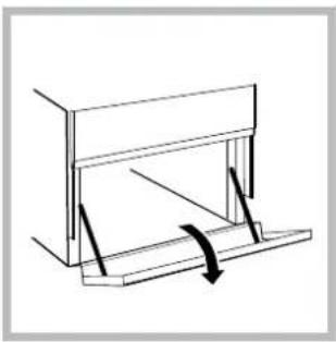
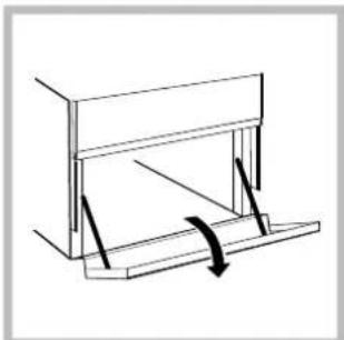
Lower oven compartment\*
There is a compartment underneath the oven that may be used to storeoven accessories or deep dishes. To open the door pull it downwards (see figure).
natural_image
Simple line drawing of a mechanical assembly with a curved arrow indicating rotation (no text or symbols)! Do not place flammable materials in the lower oven compartment.
! The internal surfaces of the compartment (where present) may become hot.
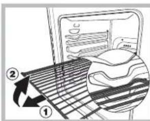
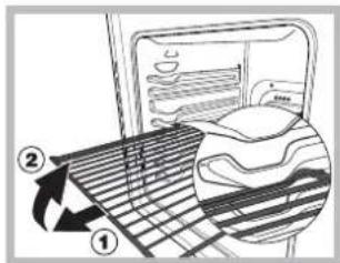
WARNING! The oven is provided with a stop system to extract the racks and prevent them from coming out of the oven.(1) As shown in the drawing, to extract them completely, simply lift the racks, holding them on the front
part, and pull (2).
* Only available in certain models.
Electronic timer\*
This function displays the time and works as a timer which counts down to zero.
! All functions will be implemented approximately 7 seconds after they have been set.
Resetting the clock
After the appliance has been connected to the power supply, or after a power cut, the clock display will begin to blink, showing the figure: 0:00
- Press button ⬇ and then buttons - and + to set the exact time. Press and hold the buttons to quicken the count upwards.
Any necessary modifications can be made by repeating the above process.
Timer feature
This function may be accessed by pressing the 🔒 button, after which the display will show the symbol ⚠. Every time the + button is pressed it corresponds to a time increase of 10 seconds, until it reaches 99 minutes and 50 seconds. After this point, each press of the button represents an increase of one minute, up to a maximum of 10 hours.
Pressing the - button reduces the time.
After the time period has been set, the timer will begin to count down. When the timer reaches zero, the buzzer will sound (this may be stopped by pressing any button).
The time may be displayed by pressing the ⏻ button, and the ⏱ symbol indicates that the timer function has been set. After approximately 7 seconds, the display will automatically revert to the timer.
Cancelling a time that has already been set
Press the - button until the display shows 0:00.
Adjusting the buzzer volume
After selecting and confirming the clock settings, use the - button to adjust the volume of the alarm buzzer.
Planning cooking with the electronic programmer\*
Setting the clock
After the appliance has been connected to the power supply, or after a blackout, the display will automatically reset to 0:00 and begin to blink. To set the time:
- Press the COOKING TIME button 📋 and the COOKING END TIME simultaneously.
- Within 4 seconds of having pressed these buttons, set the exact time by pressing the + and - buttons. The + button advances the hours and the - button decreases the hours.
Once the time has been set, the programmer automatically switches to manual mode.
Setting the timer
The timer enables a countdown to be set, when the time has elapsed a buzzer sounds.
To set the timer proceed as follows:
- press the TIMER button ⏱. The display shows:
^A 0·30. - Press the + and - buttons to set the desired time.
- When the buttons are released the timer begins
counting down and the current time appears on the display.
10:00
- After the time has elapsed a buzzer will sound, and this can be switched off by pressing any button (except the + and - buttons). The symbol ⏱ will switch off.
! The timer does not switch the oven on or off.
Adjusting the volume of the buzzer
After selecting and confirming the clock settings, use the - button to adjust the volume of the alarm buzzer.
Setting the cooking time with a delayed start
First decide which cooking mode you wish to use and set a suitable temperature using the SELECTOR and THERMOSTAT knobs on the oven.
At this point it is possible to set the cooking time:
- Press the COOKING TIME button
- Within 4 seconds of having pressed this button, set the desired amount of time by pressing the + and - buttons. If, for example, you wish to set a cooking time of 30 minutes, the display will show:

^ 0·30
-
4 seconds after the buttons are released, the current time (for example 10.00) reappears on the display with the symbol 🔊 and the letter A (AUTO). Next the desired cooking end time must be set:
-
Press the END COOKING TIME button ☐.
- Within 4 seconds of having pressed this button, adjust the cooking end time by pressing the + and - buttons. If, for example, you want cooking to end at 13.00, the display shows:
^13·00
- 4 seconds after the buttons are released, the current time (for example 10.00) reappears on the display with the letter A (AUTO).
^10·00
At this point, the oven is programmed to switch on automatically at 12:30 and switch off after 30 minutes, at 13.00.
Setting the cooking time with an immediate start Follow the above procedure for setting the cooking time (points 1-3).
! When the letter A appears, this indicates that both the cooking time and the end cooking time have been programmed in AUTO mode. To restore the oven to manual operation, after each AUTO cooking mode press the COOKING TIME 🎨 and END COOKING TIME 🎨 buttons simultaneously.
! The symbol 📊 will remain lit, along with the oven, for the entire duration of the cooking programme.
The set cooking duration can be displayed at any time by pressing the COOKING TIME button 📄, and the cooking end time may be displayed by pressing the END COOKING TIME button 📄. When the cooking time has elapsed a buzzer sounds. To stop it, press any button apart from the + and - buttons.
Cancelling a previously set cooking programme Press the COOKING TIME button 📋 and the COOKING END TIME 🌐 simultaneously.
Correcting or cancelling previously set data
The data entered can be changed at any time by pressing the corresponding button (TIMER, COOKING TIME or COOKING END TIME) and the + or - button. When the cooking time data is cancelled, the cooking end time data is also cancelled automatically, and vice
versa.
If the oven has already been programmed, it will not accept cooking end times which are before the start of the programmed cooking process.
End-cooking Timer \*
- To set the buzzer, turn the COOKING TIMER knob clockwise almost one complete revolution.
- Turn the knob anticlockwise to set the desired time: align the minutes shown on the COOKING TIMER knob with the indicator on the control panel.
- When the selected time has elapsed, a buzzer sounds and the oven turns off.
- When the oven is off the cooking timer can be used as a normal timer.
! To use the oven manually, in other words when you do not wish to use the end of cooking timer, turn the COOKING TIMER knob until it reaches the ⏻ symbol.
Oven cooking advice table
| Selector knob setting | Food to be cooked Weight (in kg) | Cooking rack position from bottom | Preheating time (minutes) | Thermostat knob setting | Cooking time (minutes) | |
| Baking | Tarts | 0.5 | 3 | 15 | 180 | 20-30 |
| Fruit cakes | 1 | 2/3 | 15 | 180 | 40-45 | |
| Plum cake | 0.7 | 3 | 15 | 180 | 40-50 | |
| Sponge cake | 0.5 | 3 | 15 | 160 | 25-30 | |
| Stuffed pancakes (on 2 racks) | 1.2 | 2-4 | 15 | 200 | 30-35 | |
| Small cakes (on 2 racks) | 0.6 | 2-4 | 15 | 190 | 20-25 | |
| Cheese puffs (on 2 racks) | 0.4 | 2-4 | 15 | 210 | 15-20 | |
| Cream puffs (on 3 racks) | 0.7 | 1-3-5 | 15 | 180 | 20-25 | |
| Biscuits (on 3 racks) | 0.7 | 1-3-5 | 15 | 180 | 20-25 | |
| Meringues (on 3 racks) | 0.5 | 1-3-5 | 15 | 90 | 180 | |
| Convection | Duck | 1 | 3 | 15 | 200 | 65-75 |
| Roast veal or beef | 1 | 3 | 15 | 200 | 70-75 | |
| Pork roast | 1 | 3 | 15 | 200 | 70-80 | |
| Biscuits (short pastry) | - | 3 | 15 | 180 | 15-20 | |
| Tarts | 1 | 3 | 15 | 180 | 30-35 | |
| Fan assisted | Pizza (on 2 racks) | 1 | 2-4 | 15 | 220 | 15-20 |
| Lasagne | 1 | 3 | 10 | 200 | 30-35 | |
| Lamb | 1 | 2 | 10 | 180 | 50-60 | |
| Roast chicken + potatoes Mackerel | 1 | 2-4 | 10 | 180 | 60-75 | |
| Plum-cake | 1 | 2 | 10 | 180 | 30-35 | |
| Cream puffs (on 2 racks) | 0.5 | 2-4 | 10 | 170 | 40-50 | |
| Biscuits (on 2 racks) | 0.5 | 2-4 | 10 | 190 | 20-25 | |
| Sponge cake (on 1 rack) | 0.5 | 2 | 10 | 180 | 10-15 | |
| Sponge cake (on 2 racks) | 1.0 | 2-4 | 10 | 170 | 15-20 | |
| Savoury pies | 1.5 | 3 | 15 | 200 | 25-30 | |
| Top Oven | Browning food to perfect cooking | -3/4 | 15 220 - | |||
| Grill | Soles and cuttlefish | 1 | 4 | 5 | Max | 8-10 |
| Squid and prawn kebabs | 1 | 4 | 5 | Max | 6-8 | |
| Cod filet | 1 | 4 | 5 | Max | 10 | |
| Grilled vegetables | 1 | 3/4 | 5 | Max | 10-15 | |
| Veal steak | 1 | 4 | 5 | Max | 15-20 | |
| Cutlets | 1 | 4 | 5 | Max | 15-20 | |
| Hamburgers | 1 | 4 | 5 | Max | 7-10 | |
| Mackerels | 1 | 4 | 5 | Max | 15-20 | |
| Toasted sandwiches | n.° 4 | 4 | 5 | Max | 2-3 | |
| Fan assisted grill | Grilled chicken | 1.5 | 3 | 5 | 200 | 55-60 |
| Cuttlefish | 1.5 | 3 | 5 | 200 | 30-35 | |
| Bottom Ventilated | Bream | 0.5 | 3 | 18 | 170-180 | 25-35 |
| Codfi sh fi llet | 0.5 | 3 | 16 | 160-170 | 15-20 | |
| Sea bass in foil | 0.5 | 3 | 24 | 200-210 | 35-45 | |
| Mixed vegetables (Ratatouille type) | 0.8 – 1,0 | 3 | 21 | 190 -200 | 50 - 60 | |
| Well-done vegetables | 1,5 – 2,0 | 3 | 20 | 180 - 190 | 55 - 60 | |
| Bottom Mode | For perfectioning cooking | |||||
! cooking times are approximate and may vary according to personal taste. When cooking using the grill or fan assisted grill, the dripping pan must always be placed on the 1st oven rack from the bottom.
! This appliance has been designed and manufactured in compliance with international safety standards. The following warnings are provided for safety reasons and must be read carefully.
General safety
- The appliance was designed for domestic use inside the home and is not intended for commercial or industrial use.
- The appliance must not be installed outdoors, even in covered areas. It is extremely dangerous to leave the appliance exposed to rain and storms.
- Do not touch the appliance with bare feet or with wet or damp hands and feet.
- The appliance must be used by adults only for the preparation of food, in accordance with the instructions provided in this booklet.
- The instruction booklet accompanies a class 1 (insulated) or class 2 - subclass 1 (recessed between 2 cupboards) appliance.
- Keep children away from the oven.
- Make sure that the power supply cables of other electrical appliances do not come into contact with the hot parts of the oven.
- The openings used for the ventilation and dispersion of heat must never be covered.
- Always use oven gloves when placing cookware in the oven or when removing it.
- Do not use flammable liquids (alcohol, petrol, etc...) near the appliance while it is in use.
- Do not place flammable material in the lower storage compartment or in the oven itself. If the appliance is switched on accidentally, it could catch fire.
- Always make sure the knobs are in the “●” position when the appliance is not in use.
- When unplugging the appliance, always pull the plug from the mains socket; do not pull on the cable.
- Never perform any cleaning or maintenance work without having disconnected the appliance from the electricity mains.
- If the appliance breaks down, under no circumstances should you attempt to repair the appliance yourself. Repairs carried out by inexperienced persons may cause injury or further malfunctioning of the appliance. Contact Assistance.
- Do not rest heavy objects on the open oven door.
- The appliance should not be operated by people (including children) with reduced physical, sensory or mental capacities, by inexperienced individuals or by anyone who is not familiar with the product. These individuals should, at the very least, be supervised by someone who assumes responsibility for their safety or receive preliminary instructions relating to the operation of the appliance.
- If the cooker is placed on a pedestal, take the necessary precautions to prevent the cooker from sliding off the pedestal itself.
Disposal
- When disposing of packaging material: observe local legislation so that the packaging may be reused.
- The European Directive 2002/96/EC relating to Waste Electrical and Electronic Equipment (WEEE) states that household appliances should not be disposed of using the normal solid urban waste cycle. Exhausted appliances should be collected separately in order to optimise the cost of re-using and recycling the materials inside the machine, while preventing potential damage to the atmosphere and to public health. The crossed-out dustbin is marked on all products to remind the owner of their obligations regarding separated waste collection. For more information relating to the correct disposal of household appliances, owners should contact their local authorities or appliance dealer.
Respecting and conserving the environment
- Always keep the oven door closed when using the GRILL and FAN-ASSISTED GRILL mode cooking. This will achieve better results while saving energy (approximately 10%).
- Whenever possible, avoid pre-heating the oven and always try to fill it. Open the oven door as little as possible because heat is lost every time it is opened. To save a substantial amount of energy, simply switch off the oven 5 to 10 minutes before the end of your planned cooking time and use the heat the oven continues to generate.
- Keep gaskets clean and tidy to prevent any door energy losses
- If you have a timed tariff electricity contract, the “delay cooking” option will make it easier to save money by moving operation to cheaper time periods.
- The base of your pot or pan should cover the hot plate. If it is smaller, precious energy will be wasted and pots that boil over leave encrusted remains that can be difficult to remove.
- Cook your food in closed pots or pans with well-fitting lids and use as little water as possible. Cooking with the lid off will greatly increase energy consumption
- Use purely flat pots and pans
- If you are cooking something that takes a long time, it's worth using a pressure cooker, which is twice as fast and saves a third of the energy.
Switching the appliance off
Disconnect your appliance from the electricity supply before carrying out any work on it.
Cleaning the appliance
! Never use steam cleaners or pressure cleaners on the appliance.
- The stainless steel or enamel-coated external parts and the rubber seals may be cleaned using a sponge that has been soaked in lukewarm water and neutral soap. Use specialised products for the removal of stubborn stains. After cleaning, rinse well and dry thoroughly. Do not use abrasive powders or corrosive substances.
- The hob grids, burner caps, flame spreader rings and burners may be removed to make cleaning easier; wash them in hot water and non-abrasive detergent, making sure all burnt-on residue is removed before drying them thoroughly.
- For hobs with electronic ignition, the terminal part of the electronic lighting devices should be cleaned frequently and the gas outlet holes should be checked for blockages.
- The inside of the oven should ideally be cleaned after each use, while it is still lukewarm. Use hot water and detergent, then rinse well and dry with a soft cloth. Do not use abrasive products.
- Clean the glass part of the oven door using a sponge and a non-abrasive cleaning product, then dry thoroughly with a soft cloth. Do not use rough abrasive material or sharp metal scrapers as these could scratch the surface and cause the glass to crack.
- The accessories can be washed like everyday crockery, and are even dishwasher safe.
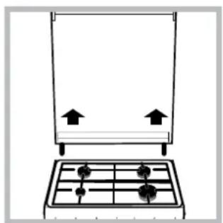
The cover\*
natural_image
Simple line drawing of a gas stove with four outlets and two upward arrows indicating airflow or movement (no text or symbols)If the cooker is fitted with a glass cover, this cover should be cleaned using lukewarm water. Do not use abrasive products. It is possible to remove the cover in order to make cleaning the area behind the hob easier. Open the cover fully and pull it upwards (see figure).
! Do not close the cover when the burners are alight or when they are still hot.
! Remove any liquid from the lid before opening it.
Inspecting the oven seals
Check the door seals around the oven regularly. If the seals are damaged, please contact your nearest Authorised After-sales Service Centre. We recommend that the oven is not used until the seals have been replaced.
Replacing the oven light bulb
- After disconnecting the oven from the electricity
mains, remove the glass lid covering the lamp socket (see figure). - Remove the light bulb and replace it with a similar one: voltage 230 V, wattage 25 W, cap E 14.
- Replace the lid and reconnect the oven to the electricity supply.
! Do not use the oven lamp as/for ambient lighting.
Gas tap maintenance
Over time, the taps may become jammed or difficult to turn. If this occurs, the tap must be replaced.
! This procedure must be performed by a qualified technician who has been authorised by the manufacturer.
Assistance
Please have the following information to hand:
• The appliance model (Mod.).
• The serial number (S/N).
This information can be found on the data plate located on the appliance and/or on the packaging.
* Only available in certain models.
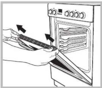
Removing and fitting the oven door:
1.Open the door
natural_image
Technical line drawing of a mechanical bracket or clamp assembly (no text or symbols)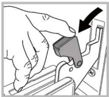
natural_image
Hand operating a mechanical component with an arrow indicating direction (no text or symbols present)- Make the hinge clamps of the oven door rotate backwards completely (see photo)
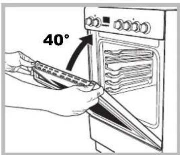
- Close the door until the clamps stop (the door will remain open for 40^ approx.) (see photo)
natural_image
Illustration of hands using a tool to adjust or install an oven with a ruler (no text or symbols visible)- Press the two buttons on the upper profile and
natural_image
Illustration of a hand using a spatula to clean or adjust the oven with a tray (no text or symbols visible)extract the profile (see photo)
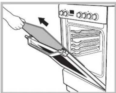
-
Remove the glass sheet and do the cleaning as indicated in chapter: "Care and maintenance".
-
Replace the glass.
WARNING! Oven must not be operated with inner door glass removed!
WARNING! When reassembling the inner door glass insert the glass panel correctly so that the text written on the panel is not reversed and can be easily legible.
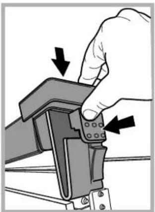
- Replace the profile, a click will indicate that the part is positioned correctly.
8.Open the door completely.
- Close the supports (see photo).
natural_image
Hand holding a mechanical component with arrows indicating force or movement (no text or symbols)- Now the door can be completely closed and the oven can be started for normal use.
Steam-Assisted Oven Cleaning
This method of cleaning is recommended especially after cooking very fatty (roasted)meats.
This cleaning process allows to facilitate the removal of dirt of the walls of the oven by the generation of steam that is created inside the oven cavity for easier cleaning.
! Important! Before you start steam -cleaning:
-Remove any food residue and grease from the bottom of the oven.
- Remove any oven accessories (grids and drip pans).
Perform the above operations according to the following procedure:
- pour 300ml of water into the baking tray in the oven, placing it in the bottom shelf. In the models where the drip pan is not present, use a baking sheet and place it on the grill at the bottom shelf;
- select the function of the oven BOTTOM |_
and set the temperature to 100^ C;
- keep it in the oven for 15min;
- turn off the oven;
- Once cooled the oven, you can open the door to complete the cleaning with water and a damp cloth;
- eliminate any residual water from the cavity after finishing cleaning
When the steam -cleaning is done, after cooking especially fatty foods, or when grease is difficult to remove, you may need to complete the cleaning with the traditional method, described in the previous paragraph.
! Perform cleaning only in the cold oven!
natural_image
Simple line drawing of a house interior with a stove and air duct (no text or symbols)natural_image
Simple line drawing of a house with a stove and heating elements (no text or symbols)natural_image
Pure 3D geometric diagram showing two blocks with a handle, no text or symbols presentKlasa 2 podklasa 1
Poziomowanie kuchni
natural_image
Pure diagram of a mechanical or electrical component with no text, numbers, or symbols visiblenatural_image
Mechanical component diagram showing a cylindrical shaft with an upward arrow indicating motion (no text or symbols)natural_image
Technical line drawing of a mechanical assembly with a central pin and base mount (no text or symbols)natural_image
Exploded view of a mechanical component showing internal parts and housing (no text or symbols)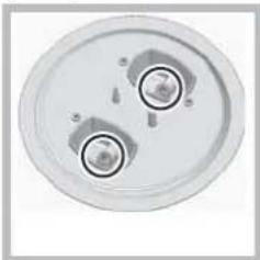
natural_image
Top-down view of a circular mechanical component with two central holes and mounting holes (no text or symbols visible)natural_image
Technical diagram of a mechanical component with an inset close-up showing a detail (no text or symbols)natural_image
Technical diagram of a mechanical assembly with labeled components (X, C) and no readable text or symbols.Program PIEKARNIK DLA PIZZY
The central part of the top heating element is switched on. The high and direct temperature of the grill is recommended for food that requires a high surface temperature (veal and beef steaks, fillet steak and entrecôte). This cooking mode uses a limited amount of energy and is ideal for grilling. Place the food in the centre of the rack, as it will not be cooked properly if it is placed in the corners.


GÓRNA GRZAŁKA
natural_image
Simple line drawing of a mechanical device with a curved arrow indicating rotation (no text or symbols)natural_image
Line drawing of a microwave oven with a handle and tray (no text or symbols)natural_image
Simple line drawing of a kitchen appliance with a pan and side-mounted dish (no text or symbols)natural_image
Technical line drawing of a mechanical bracket or support structure (no text or symbols)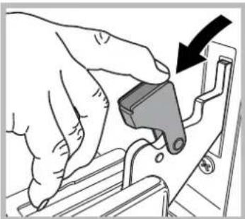
natural_image
Illustration of a hand using a tool to adjust or install a mechanical component (no text or symbols visible)natural_image
Illustration of hands using a tool to clean or install an oven (no text or symbols visible)natural_image
Illustration of a hand using a spatula to spread food from an oven (no text or symbols visible)natural_image
Hand operating a mechanical clamp or bracket with arrows indicating force direction (no text or symbols present)natural_image
Simple line drawing of a house interior with a stove and roof, no text or symbols presentnatural_image
Simple line drawing of a house with an oven, roof, and electrical connections (no text or symbols)Důmai iđpučiami tiesiai á kaminí ar đakotř důmtraukio sistemí (taikoma maisto ruodimo prietaisams)
natural_image
Simple diagram showing a gray rectangle with a black arrow pointing to it and a small black arrow labeled 'SARMA' pointing downward (no text or symbols beyond the arrow)Idlyginimas
natural_image
Mechanical component diagram showing a cylindrical shaft with a directional arrow indicating motion (no text or symbols)natural_image
Technical line drawing of a mechanical assembly with a tool inserted into a circular component (no text or symbols)! Kaitlentës degikliams nereikia pirminio oro sureguliavimo.
! Sureguliavć prietaisí taip, kad já bútř galima naudoti su skirtingř tipř dujomis, pakeiskite sení etiketíc nauja, kuri atitiktř
naují dujř tipř (dias etiketes galima ásigyti id ágalioto techninës prietiúros centro).
natural_image
Technical diagram of a mechanical component with a magnified inset showing a detail (no text or symbols)natural_image
Exploded view diagram of a mechanical assembly with gears and housing (no text or labels)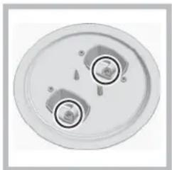
natural_image
Top-down view of a circular mechanical component with two circular features and mounting holes (no text or symbols visible)natural_image
Line drawing of a laptop interior with a handle and cable, no text or symbols presentPICOS ORKAITĖS REŽIMAS
natural_image
Simple line drawing of a mechanical assembly with a lever and base (no text or symbols)Po orkaite yra skyrius, kuriame galima laikyti orkaitës priedus ar gilias lëkdtes. Norëdami atidaryti dureles, stumtelëkite jas țemyn (tr. pav.).
! Nedëkite degiř medtiagř á apatiná orkaitës skyriř.
natural_image
Simple line drawing of a gas stove with upward arrows indicating direction (no text or symbols)Stiklinis viryklës gaubtas valomas diltu vandeniu. Nevalykite braitomaisiais valikliais.
Norint palengvinti valymí uṭ kaitlentës galo, gaubtī galima nuimti. Já visiđkai atidarykite ir pakelkite aukdtyn (tr. pav.).
natural_image
Technical line drawing of a mechanical bracket or clamp assembly (no text or symbols)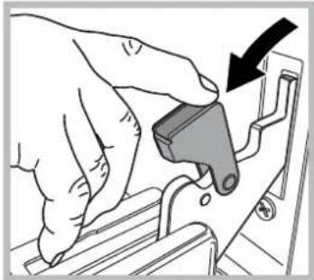
natural_image
Illustration of a hand using a tool to adjust or install a mechanical component (no text or symbols visible)natural_image
Illustration of hands using a tool to adjust or install a oven (no text or symbols visible)natural_image
Illustration of a hand using a tool to clean or install a oven with a rack inside (no text or symbols visible)natural_image
Hand holding a mechanical component with arrows indicating force or movement (no text or symbols)Ventilâcijas atvere
dedzinâdanai nepiecieđamâ
gaisa plûsmai
B
! Pçc tam, kad ierîce ir lietota ilgstodi, ieteicams atvçrt logu vai palielinât jebkâdu izmantoto ventilatoru darbîbas âtrumu.
Atbrîvođanâs no dûmiem
natural_image
Diagram of a mechanical or electrical system with a central device and surrounding components (no text or symbols)Tvaiki tiek izvadîti tiedi ârâ
natural_image
Simple line drawing of a house with an oven and heating elements (no text or symbols)Tvaiki tiek izvadîti pa dûmvađu vai sazarotu dûmvađu sistçmu (rezervçta çdiena gatavođanas ierîcçm)
! Sađišdrinâtâs deggâzes ir smagâkas par gaisu, un tâs nosçtas uz grîdas, tâpçc visâm telpâm, kur novietoti LPG cilindri, ir nepieciedamas izejas uz âru, lai visas gâzu noplüdes varçtu âtri izvadît.
Đâ iemesla dçđ gan dadčji, gan pilnîgi piepildítos LPG cilindrus nedrîkst ierîkot vai novietot glabâdanai telpâs vai noliktavâs, kas atrodas zem pirmâ stâva lîmeňa (pagrabos un tamlîdzîgâs vietâs). Telpâ ir jânovieto tikai izmantotais cilindrs; tas arî nedrîkst atrasties siltuma avotu tuvumâ (pie krâsnîm, dûmvadiem, plîtîm), kas cilindra temperatúru varçtu paaugstinât virs 50°C.
Novietođana un lîmeňođana
! lerîci drîkst ierîkot blakus virtuves skapjiem, kuru augstums nepârsniedz plîts virsmas augstumu.
! Sienai, pret kuru ir vçrsta ierîces aizmugurçjâ dad'a, ir jâbût izgatavotai no ugunsdrođa un siltumizturîga materiâla (90°C temp.).
lerîces pareiza ierîkođana.
- Novietojiet to virtuvç, çdamistabâ vai dzîvojamâ istabâ (bet ne vannas istabâ).
- Ja plîts virsma ir augståka par virtuves skapi, starp plîti un virtuves skapi jânodrođina vismaz 200 mm atstatums.
- Ja plîts ir ierîkota zem sienas skapja, starp sienas skapi un plîts virsmu ir jâbût vismaz 420 mm atstatumam.
- Ja plīts ir ierīkota zem sienas skapja, starp sienas skapi un plīts virsmu ir jābūt vismaz 420 mm atstatumam.

Ja sienas skapji ir no viegli uzliesmojođa materiâla, atstatums jâpalielina lîdz 700 mm (skatît attçlu);
- Aiz plîts nedrîkst ierîkot țalûzijas — țalûzijâm jâbût vismaz 200 mm attâlumâ no plîts sâniem.
• Tvaika nosúcçjs ir jâierîko saskaňâ ar
natural_image
Simple diagram showing a gray rectangle with a downward arrow and a small black arrow pointing to it (no text or symbols)stûrî tam îpađi paredzçtâs vietâs pieskrüvcjiet regulçamas kâjas (skatît attçlu).
natural_image
Mechanical component diagram showing a cylindrical shaft with a directional arrow indicating motion (no text or symbols)Kâjas* var ieskrüvçt attiecîgajâs atverçs zem plîts pamatnes.
Elektrîbas pieslçgdana
lerikojiet standarta spraudni atbilstodi slodzei, kas noradita ierices tehnisko datu plaksnitç (skatit tehnisko datu tabulu).
lerîce ir jâpieslçdz tieđi elektrotîklam, starp ierîci un elektrotîklu ierîkojot vienpola slçdzi, kura minimâlais attâlums staro kontaktiem ir 3 mm. Slçdzim jâbût piemçrotam norâdîtajam strâvas stiprumam un jâatbilst NFC 15-100 noteikumiem (slçdzis nedrîkst atvienot zemçjuma vadu). Elektrîbas vads jânovieto tâ, lai tas nesaskartos ar detađâm, kuru temperatûra var paaugstinâties virs 50°C.
Pirms ierîces pieslçgđanas elektropadevei pârbaudiet, vai:
- ierîce ir iezemçta un spraudnis atbilst normatîvo aktu prasîbâm;
- rozete atbilst ierîces maksimâlajai jaudai, kas ir norâdîta uz tehnisko datu plâksnîtes;
- elektrotikla spriegums ir tehnisko datu plâksnîtç norâdîtajâ diapazonâ;
- rozete ir savietojama ar ierîces spraudni. Ja rozete
natural_image
Technical line drawing of a mechanical assembly with a tool inserted into a circular component (no text or symbols)Plîts virsmas degđ'u minimâlais iestatîjums ir jâregulç tâlâk aprakstîtajâ veidâ.
- Pagrieziet krânu lîdz minimâlajai pozîcijai.
- Nošemiet grozâmo slçdzi un
pielâgojiet regulçđanas skrûvi, kas atrodas krâna rçdzç vai blakus tai, lîdz liesma ir maza, bet pastâvîga.
! Ja ierîce ir pievienota sadîidrinâtas gâzes padevei, regulçđanas skrûve ir jânostiprina pçc iespcjas ciedâk.
3. Kamçr deglis ir iedegts, vairâkas reizes strauji mainiet grozâmâ slçdța pozîciju no mazâkâs lîdz lielâkajai pozîcijai un otrâdi, tâ pârbaudot, vai liesmas neizdziest.
! Plîts virsmas degd'iem nav nepieciedama primârâ gaisa regulçdana.
! Pcc ierîces noregulçđanas, lai to varçtu izmantot ar cita veida gâzi, iepriekđcjo vçrtcjuma marícjumu nomainiet pret jauno, kas atbilst jaunajam gâzes veidam (đie marícjumi ir pieejami pilnvarotos tehniskâs palîdzîbas centros).
! Ja izmantotâs gâzes spiediens ir citâds (vai mazliet atdîirîgs) nekâ ieteicamais spiediens, ieplüdes caurud'vadam ir jäpiestiprina piemçrots spiediena regulators, kas atbilst spçkâ esodajiem noteikumiem saistîbâ ar gâzes caurud'vadu noteikumiem.
Drošības kēde
natural_image
Technical diagram of a mechanical component with a magnified inset showing a detail (no text or symbols)natural_image
3D rendered mechanical component with internal gears and housing (no text or symbols)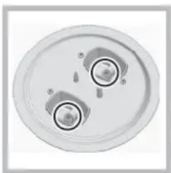
natural_image
Top-down view of a circular mechanical component with two central holes and mounting holes (no text or symbols visible)- Deglu gaisa padeves regulēšana: Nav nepiecieama.
Ja ierîce ir aprîkota ar elektronisko iedegđanas ierîci* (C), nospiediet DEGĐA slçdzi un pagrieziet to pretçji pulksteñrâdîtâja virzienam, minimâlâ liesmas iestatîjuma virzienâ, lîdz deglis iedegas. Atlaitot grozámo slçdzi, deglis
var izdzist. Tâdâ gadîjumâ atkârtojiet do darbîbu, turot slçdzi nospiestu ilgâku laiku.
Ja ierîce ir aprîkota ar drođîbas ierîci pret liesmu izdziđanu (X), nospiediet un aptuveni 3–7 sekundes turiet nospiestu DEGĐA slçdzi, lai liesma neizdzistu un ierîce tiktu aktivizçta.
! Ja liesma nejauđi izdziest, izslçdziet degli un pagaidiet vismaz vienu minüti, pirms mçëinât to iedegt atkal.
Lai degli izslęgtu, pagrieziet rotęjođo slędzi, lîdz tas ir pozîcijâ •.
natural_image
Line drawing of a microwave oven with a hand pointing to the interior (no text or symbols)Lai lietotu iesmu, rikojieties saskana ar turpmak mineta-jam instrukcijam:
- novietojiet cepeštauku pannu 1. pozicija;
- uzstadiet iesma balstu 4. pozicija un ievietojiet iesmu cepeškrasns aizmugureja panela atvere;
- aktivizejiet iesmu, SE-LEKTORA sledzi parsledzot pozicija.
Cepeđkrâsns apakđçjais nodalijums\*
Zem cepedkrâsns atrodas nodalîjums, ko var izmantot,
natural_image
Simple line drawing of a mechanical or architectural component with no text, numbers, or symbolslai glabátu cepeđkrâsns piederumus vai dzid'os traukus. Lai atvçrtu dâ nodalîjuma durtiñas, pavelciet tâs uz leju (skatît attçlu).
! Cepedkrâsns apakđçjâ nodalijumâ nedrîkst novietot viegli uzliesmojođus materiâlus.
! Nodalijuma (ja cepeđkrâsns ar to ir aprikota) iekđçjâs virsmas lietođanas laikâ var sakarst.
natural_image
Simple line drawing of a kitchen appliance with a grid and two arrows indicating upward motion (no text or symbols)natural_image
Technical line drawing of a mechanical bracket assembly (no text or symbols)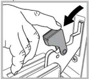
natural_image
Illustration of a hand using a tool to adjust or install a mechanical component (no text or symbols visible)natural_image
Illustration of hands using a tool to adjust or install an oven with a tray (no text or symbols visible)natural_image
Illustration of a hand using a spatula to lift a kitchen oven with a handle (no text or symbols)natural_image
Hand operating a mechanical component with arrows indicating force or movement (no text or symbols present)natural_image
Simple line drawing of a room interior with doors, windows, and a chimney (no text or symbols)natural_image
Pure technical diagram of a mechanical or electrical assembly without any text, numbers, or symbolsnatural_image
Simple line drawing of a house interior with a stove and heating elements (no text or symbols)natural_image
Simple diagram showing a gray rectangle with a downward arrow and a small black arrow pointing to it (no text or symbols)natural_image
Mechanical component diagram showing a cylindrical shaft with a downward rotation arrow (no text or symbols)Elektriühendused
natural_image
Technical line drawing of a mechanical assembly with a tool inserted into a circular component (no text or symbols)natural_image
Technical diagram of a mechanical component with an inset close-up showing a detail (no text or symbols)natural_image
Exploded view diagram of a mechanical assembly (no text or symbols visible)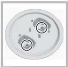
natural_image
Top-down view of a circular mechanical component with two circular features and mounting holes (no text or symbols visible)natural_image
Line drawing of a laptop interior with a handle and scroll, no text or symbols presentnatural_image
Simple line drawing of a mechanical or architectural component with a curved arrow indicating rotation (no text or symbols)!Ärge hoidke ahju alumises osas asuvas panipaigas kergestisüttivaid materjale.
natural_image
Simple line drawing of a kitchen appliance with a pan and grid (no text or symbols)natural_image
Technical line drawing of a mechanical clamp or bracket assembly (no text or symbols)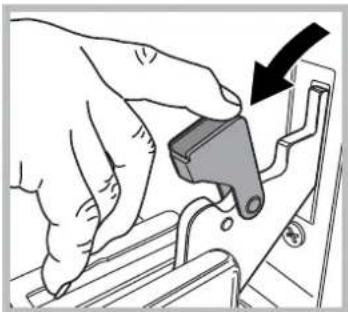
natural_image
Illustration of a hand using a tool to adjust or install a mechanical component (no text or symbols visible)natural_image
Illustration of hands using a tool to adjust or install a oven with a tray (no text or symbols visible)natural_image
Illustration of a hand using a tool to cut the oven into a rack (no text or symbols visible)- Pange klaas tagasi.
natural_image
Hand holding a mechanical component with arrows indicating force or movement (no text or symbols present)
- Operating Instructions COOKER AND OVEN
- Contents
- PL
- Polski
- Instrukcja obsługi
- KUCHENKA I PIEKARNIK
- UWAGAUWAGA
- Description of the appliance Overall view
- Description of the appliance Control panel
- Room ventilation
- Disposing of combustion fumes
- Positioning and levelling
- Levelling
- Electrical connection
- ! The manufacturer declines any liability should these safety measures not be observed.
- Gas connection
- Gas connection using a flexible rubber hose
- Connecting a flexible jointless stainless steel pipe to a threaded attachment
- Checking the tightness of the connection
- Adapting to different types of gas
- Adapting the hob
- Replacing the Triple ring burner nozzles \*
- Start-up and use
- Using the hob
- Lighting the burners
- Practical advice on using the burners
- Using the oven
- THERMOSTAT indicator light
- Oven light
- Timer\*
- Cooking modes
- BAKING mode
- CONVECTION mode
- FAN ASSISTED mode
- OVEN VON mode
- PIZZA modemode
- DOUBLE GRILL mode
- F FAMSSISTED DOUBLE GRILL mode
- DEFROSTING mode
- BOTTOM VENTILATED mode
- BOTTOM mode BOTTOM mode
- Practical cooking advice
- Cooking on several shelves simultaneously
- Rotisserie \*
- Lower oven compartment\*
- Electronic timer\*
- Resetting the clock
- Timer feature
- Cancelling a time that has already been set
- Adjusting the buzzer volume
- Planning cooking with the electronic programmer\*
- Setting the clock
- Setting the timer
- 10:00
- Adjusting the volume of the buzzer
- Setting the cooking time with a delayed start
- ^13·00
- ^10·00
- Correcting or cancelling previously set data
- End-cooking Timer \*
- General safety
- Disposal
- Respecting and conserving the environment
- Switching the appliance off
- Cleaning the appliance
- The cover\*
- Inspecting the oven seals
- Replacing the oven light bulb
- Gas tap maintenance
- Assistance
- Removing and fitting the oven door:
- WARNING! Oven must not be operated with inner door glass removed!
- Steam-Assisted Oven Cleaning
- Poziomowanie kuchni
- Program PIEKARNIK DLA PIZZY
- GÓRNA GRZAŁKA
- Idlyginimas
- PICOS ORKAITĖS REŽIMAS
- Atbrîvođanâs no dûmiem
- Novietođana un lîmeňođana
- Elektrîbas pieslçgdana
- Drošības kēde
- Cepeđkrâsns apakđçjais nodalijums\*
- Elektriühendused
Brand : INDESIT
Model : I5GMH5AG(W) U
Category : Cooker