
DH38SS - Rotary hammer HiKOKI - Free user manual and instructions
Find the device manual for free DH38SS HiKOKI in PDF.


| Product Type | Rotary Hammer |
| Brand | HiKOKI |
| Model | DH38SS |
| Power Input | 950 W |
| Voltage | 220 V ~ |
| No Load Speed | 620 /min |
| Full-Load Impact Rate | 2800 /min |
| Drill Capacity (Concrete) | 38 mm |
| Core Bit Capacity | 105 mm |
| Weight (without cord, side handle) | 6.4 kg |
| Side Handle | Included |
| Carrying Case | Included (Molded plastic) |
| Safety Clutch | Built-in |
| Vibration Control | Side handle for better grip |
| Operating Modes | Rotation + Hammering, Hammering only |
| Recommended Lubricant | HiKOKI Electric Hammer Grease A |
| Grease Replacement Interval | Every 6 months |
| Carbon Brush Type | Auto-stop type (replace when worn) |
| Tool Shank Type | Hexagonal (for bits and bull points) |
| Optional Accessories | Drill bits, core bits, chisels, anchor adapter, taper shank adapter, etc. |
Frequently Asked Questions - DH38SS HiKOKI
User questions about DH38SS HiKOKI
0 question about this device. Answer the ones you know or ask your own.
Ask a new question about this device
Download the instructions for your Rotary hammer in PDF format for free! Find your manual DH38SS - HiKOKI and take your electronic device back in hand. On this page are published all the documents necessary for the use of your device. DH38SS by HiKOKI.
USER MANUAL DH38SS HiKOKI
natural_image
Line drawing of a drill bit with a circular outline (no text or symbols)保留备用
Keep for future reference

使用说明书
Handling instructions

目次
电动工具通用安全警告 2
电锤使用安全警告....4
符号....4
规格....5
标准附件....5
选购附件(分开销售)....5
用途....7
作业之前....7
当按钮没有顺畅动作时....8
使用手提电锤的方法....8
使用自钻锚栓进行钻孔和打入作业……9
操作取心钻具的方法....10
更换润滑油....11
维护和检查....11
维修零部件一览表....13
电动工具通用安全警告
警告!
阅读所有警告和所有说明。
W1/4 (No. 20), W5/16 (No. 25), W3/8 (No. 30),
W1/2 (No. 40), W5/8 (No. 50)
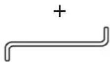
(2) 扳键
○ 破碎 (锤击)

(1) 尖凿
总长:280,400 mm
○ 开槽和饰边(锤击)

(1) 冷钻
总长:280,450 mm
○ 切柏油(锤击)
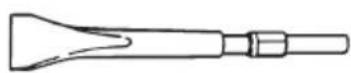
(1) 刀具
○ 电动锤润滑油 A
500g (在油罐内)
70g (在管内)
30g (在管内)
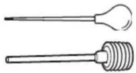
○ 喷射器(用于清除切层)
natural_image
Two types of laboratory test tubes: a pointed bulb and a coiled spring (no text or labels)用途
natural_image
Line drawing of a tool being dispensed into a cylindrical component (no text or symbols)工具柄
图1
夹持器边缘
natural_image
Illustration of two hands using a drill bit presser to lift a screwdriver (no text or symbols present)图5 图6
注意!
natural_image
Line drawing of a manual drill bit with a threaded shaft (no text or symbols)图 16
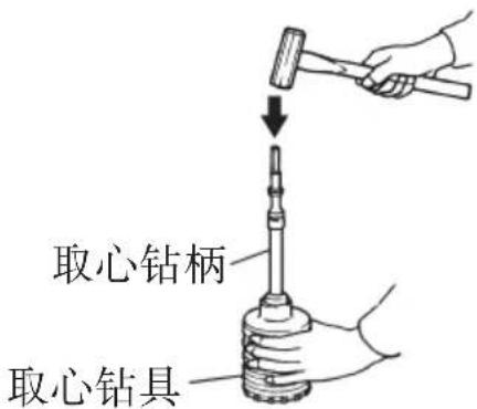
图 17
更换润滑油
中文
| 项目号 | 代码号 | 使用数 | 备注 |
| 1 | 331241 | 1 | |
| 2 | 331243 | 1 | |
| 3 | 991697 | 2 D4×20 | |
| 4 | 981942 | 4 M6×25 | |
| 5 | 331238 | 1 | |
| 6 | 319572 | 1 S-25 | |
| 7 | 331244 | 1 | |
| 8 | 331242 | 2 | |
| 9 | 990134 | 2 | |
| 10 | 331240 | 1 | |
| 11 | 331239 | 1 | |
| 12 | 331237 | 1 | |
| 13 | 991712 | 4 M6×25 | |
| 14 | 956996 | 1 1AS-60 | |
| 15 | 321843 | 1 | |
| 16 | 331236 | 1 | |
| 17 | 331222 | 1 | |
| 18 | 313396 | 1 | |
| 19 | 331223 | 1 | |
| 20 | 331224 | 1 | |
| 21 | 321835 | 1 | |
| 22 | 331225 | 1 | |
| 23 | 331227 | 1 | |
| 24 | 321832 | 1 | |
| 25 | 331228 | 1 | |
| 26 | 331226 | 1 | |
| 27 | 331232 | 2 | |
| 28 | 331230 | 1 | |
| 29 | 331229 | 1 | |
| 30 | 331231 | 1 | |
| 31 | 331233 | 1 | |
| 32 | 331234 | 1 | |
| 33 | 331235 | 1 | |
| 34 | 986104 | 2 | |
| 35 | 331221 | 1 | |
| 36 | 326369 | 1 | |
| 37 | 321285 | 1 | |
| 38 | 6201DD | 1 | 6201DDCMPS2L |
| 39 | 325003 | 1 | |
| 40 | 360875E | 1 220V-230V | |
| 41 | 331252 | 1 |
| 项目号 | 代码号 | 使用数 | 备注 |
| 42 | 953174 | 2 D5×55 | |
| 43 | 340753E | 1 220V-230V | “44” |
| 44 | 930703 | 2 | |
| 45 | 331251 | 1 “86, 87” | |
| 46 | 331210 | 1 “47-49, 51-59” | |
| 47 | 331211 | 1 | |
| 48 | 944109 | 2 3×3×8 | |
| 49 | 331212 | 1 | |
| 50 | 313050 | 1 | |
| 51 | 6002DD | 1 | 6002DDCMPS2L |
| 52 | 331213 | 1 | |
| 53 | 331214 | 1 | |
| 54 | 321281 | 1 | |
| 55 | 331218 | 10 | |
| 56 | 331217 | 10 | |
| 57 | 331215 | 1 | |
| 58 | 331219 | 1 | |
| 59 | 629VVM | 1 629VVC2PS2L | |
| 60 | 331220 | 1 | |
| 61 | 992803 | 2 M6×20 | |
| 62 | 986940 | 4 M6×45 | |
| 63 | ——2 | ||
| 64 | 994192 | 6 M5×16 | |
| 65 | 331245 | 1 | |
| 66 | 878713 | 1 | |
| 67 | 331207 | 1 | |
| 68 | 331549 | 1 | |
| 69 | 939540 | 1 | |
| 70 | 331208 | 1 | |
| 71 | 948391 | 1 | |
| 72 | 6203DD | 1 | 6203DDCMPS2L |
| 73 | 996363 | 1 S-40 | |
| 74 | 321274 | 1 | |
| 75 | 331209 | 1 | |
| 76 | 939299 | 1 M661 | |
| 77 | 331253 | 1 | |
| 78 | 307947 | 1 M6×12 | |
| 79 | 331248 | 1 | |
| 80 | 949556 | 1 M6 | |
| 81 | 331247 | 1 | |
| 82 | 331246 | 1 | |
项目号 代码号 使用数 备注
| 83 330209 1 |
| 84 945161 2 |
| 85 999043 2 |
| 86 958900 2 |
| 87 938477 2 M5×8 |
| 88 982631 1 |
| 89 608VVM 1 608VVC2PS2L |
| 90 331254 1 |
| 91 331202 1 |
| 92 302089 4 D5×20 |
| 93 331203 1 |
| 94 331204 1 |
| 95 330216 1 270L |
| 96 959141 1 |
| 97 ——1 |
| 98 500457Z 1 |
| 99 940778 1 D10.7 |
| 100 981974 1 |
| 101 313093 1 |
| 102 938307 1 |
| 103 959141 1 |
| 104 960266 1 |
| 105 984750 2 D4×16 |
| 106 331205 1 |
| 107 307028 2 D4×25 |
| 108 331547 1 |
| 501 331206 1 |
CONTENTS
GENERAL POWER TOOL SAFETY WARNINGS ....16
ROTARY HAMMER SAFETY WARNINGS ....18
SYMBOL....19
SPECIFICATIONS....19
STANDARD ACCESSORIES 19
OPTIONAL ACCESSORIES (sold separately)....20
APPLICATIONS....21
HOW TO HANDLE A CORE BIT ....25
HOW TO REPLACE GREASE 26
MAINTENANCE AND INSPECTION 26
SERVICE PARTS LIST 28
GENERAL POWER TOOL SAFETY WARNINGS

WARNING
Read all safety warnings and all instructions.
Failure to follow the warnings and instructions may result in electric shock, fire and/or serious injury.
Save all warnings and instructions for future reference.
The term “power tool” in the warnings refers to your mains-operated (corded) power tool or battery-operated (cordless) power tool.
1) Work area safety
a) Keep work area clean and well lit.
Cluttered or dark areas invite accidents.
b) Do not operate power tools in explosive atmospheres, such as in the presence of fl ammable liquids, gases or dust.
Power tools create sparks which may ignite the dust or fumes.
c) Keep children and bystanders away while operating a power tool.
Distractions can cause you to lose control.
2) Electrical safety
a) Power tool plugs must match the outlet.
Never modify the plug in any way.
Do not use any adapter plugs with earthed (grounded) power tools.
Unmodified plugs and matching outlets will reduce risk of electric shock.
b) Avoid body contact with earthed or grounded surfaces, such as pipes, radiators, ranges and refrigerators.
There is an increased risk of electric shock if your body is earthed or grounded.
c) Do not expose power tools to rain or wet conditions.
Water entering a power tool will increase the risk of electric shock.
d) Do not abuse the cord. Never use the cord for carrying, pulling or unplugging the power tool.
Keep cord away from heat, oil, sharp edges or moving parts.
Damaged or entangled cords increase the risk of electric shock.
e) When operating a power tool outdoors, use an extension cord suitable for outdoor use.
Use of a cord suitable for outdoor use reduces the risk of electric shock.
f) If operating a power tool in a damp location is unavoidable, use a residual current device (RCD) protected supply.
Use of an RCD reduces the risk of electric shock.
3) Personal safety
a) Stay alert, watch what you are doing and use common sense when operating a power tool.
Do not use a power tool while you are tired or under the influence of drugs, alcohol or medication.
A moment of inattention while operating power tools may result in serious personal injury.
b) Use personal protective equipment. Always wear eye protection.
Protective equipment such as dust mask, non-skid safety shoes, hard hat, or hearing protection used for appropriate conditions will reduce personal injuries.
c) Prevent unintentional starting. Ensure the switch is in the off position before connecting to power source and/or battery pack, picking up or carrying the tool.
Carrying power tools with your finger on the switch or energising power tools that have the switch on invites accidents.
d) Remove any adjusting key or wrench before turning the power tool on.
A wrench or a key left attached to a rotating part of the power tool may result in personal injury.
e) Do not overreach. Keep proper footing and balance at all times.
This enables better control of the power tool in unexpected situations.
f) Dress properly. Do not wear loose clothing or jewellery. Keep your hair, clothing and gloves away from moving parts.
Loose clothes, jewellery or long hair can be caught in moving parts.
g) If devices are provided for the connection of dust extraction and collection facilities, ensure these are connected and properly used.
Use of dust collection can reduce dust-related hazards.
4) Power tool use and care
a) Do not force the power tool. Use the correct power tool for your application.
The correct power tool will do the job better and safer at the rate for which it was designed.
English
b) Do not use the power tool if the switch does not turn it on and off.
Any power tool that cannot be controlled with the switch is dangerous and must be repaired.
c) Disconnect the plug from the power source and/or the battery pack from the power tool before making any adjustments, changing accessories, or storing power tools.
Such preventive safety measures reduce the risk of starting the power tool accidentally.
d) Store idle power tools out of the reach of children and do not allow persons unfamiliar with the power tool or these instructions to operate the power tool.
Power tools are dangerous in the hands of untrained users.
e) Maintain power tools. Check for misalignment or binding of moving parts, breakage of parts and any other condition that may affect the power tool's operation.
If damaged, have the power tool repaired before use.
Many accidents are caused by poorly maintained power tools.
f) Keep cutting tools sharp and clean.
Properly maintained cutting tools with sharp cutting edges are less likely to bind and are easier to control.
g) Use the power tool, accessories and tool bits etc. in accordance with these instructions, taking into account the working conditions and the work to be performed.
Use of the power tool for operations different from those intended could result in a hazardous situation.
5) Service
a) Have your power tool serviced by a qualified repair person using only identical replacement parts.
This will ensure that the safety of the power tool is maintained.
CAUTION
Keep children and infi rm persons away.
When not in use, tools should be stored out of reach of children and infirm persons.
ROTARY HAMMER SAFETY WARNINGS
- Wear ear protectors
Exposure to noise can cause hearing loss.
- Use auxiliary handles supplied with the tool.
Loss of control can cause personal injury.
-
Hold power tool by insulated gripping surfaces, when performing an operation where the cutting accessory may contact hidden wiring or its own cord. Cutting accessory contacting a “live” wire may make exposed metal parts of the power tool “live” and could give the operator an electric shock.
-
Do not touch the bit during or immediately after operation. The bit becomes very hot during operation and could cause serious burns.
-
Before starting to break, chip or drill into a wall, floor or ceiling, thoroughly confirm that such items as electric cables or conduits are not buried inside.
- Always hold the body handle and side handle of the power tool firmly. Otherwise the counterforce produced may result in inaccurate and even dangerous operation.
- Wear a dust mask
Do not inhale the harmful dusts generated in drilling or chiseling operation. The dust can endanger the health of yourself and bystanders.
SYMBOL
WARNING
The following show symbols used for the machine. Be sure that you understand their meaning before use.

To reduce the risk of injury, user must read instruction manual.
SPECIFICATIONS
| Voltage 220 V | ~ |
| Power input 950 W | |
| Capacity | Drill bit: 38 mmCore bit: 105 mm |
| No load speed 620 /min | |
| Full-load impact rate 2800 /min | |
| Weight (without cord, side handle) 6.4 kg |
STANDARD ACCESSORIES
In addition to the main unit (1 unit), the package contains the accessories listed in the below.
| Case (Molded plastic) | 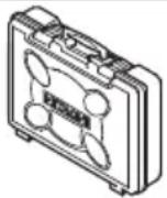 | 1 |
| Side Handle | 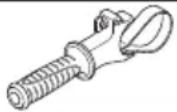 | 1 |
OPTIONAL ACCESSORIES (sold separately)
○ Through-hole drilling (Rotation + Hammering)

(1) Drill bit (hexagon shank)
Overall length: 280, 400, 505 mm
External dia.: 16, 19, 22, 25, 28, 32, 38 mm
○ Anchor hole drilling (Rotation + Hammering)
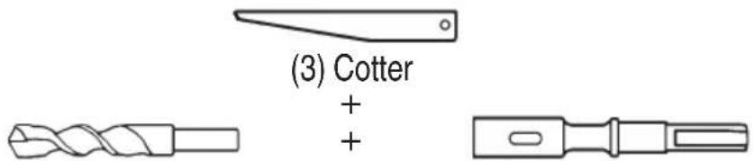
(1) Drill bit (taper shank)
External dia.: 11, 12, 14.3, 14.5, 17.5, 21.5 mm
(2) Taper shank adapter
| Taper shank adapter Application drill bit | |
| Morse taper (No. 1) Drill bit | (taper shank) 11, 12, 14.3, 14.5, 17.5 mm |
| Morse taper (No. 2) Drill bit | (tape shank) 21.5 mm |
| A-taper | Taper shank adapter formed A-taper or B-taper is provided as optional accessory, but drill bit for it is not provided. |
| B-taper | |
○ Large dia. hole boring (Rotation + Hammering)

natural_image
Five different types of screwdrivers and end caps shown in line drawings (no text or symbols)(2) Core bit (3) Core bit shank(Guide plate)(1) Center pin
(1) Center pin
● Applied to core bits from 38 mm to 105 mm
● Applied to core bits 32 mm and 35 mm
NOTE
Do not use core bits 25 mm or 29 mm.
(2) Core bit
● External dia. 25, 29, 32, 35, 38, 45, 54, 64, 79, 94, 105 mm
(with guide plate, not applicable to cores 25 mm or 29 mm)
(3) Core bit shank
● Applied to core bits above 38 mm
● Applied to core bits below 35 mm
○ Anchor work (for self-anchors)

(1) Anchor adapter (for Rotation + Hammering)
Anchor size:
W1/4 (No. 20), W5/16 (No. 25), W3/8 (No. 30),
W1/2 (No. 40), W5/8 (No. 50)
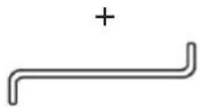
(2) Drift key
○ Crushing (Hammering)

(1) Bull point
Overall length: 280, 400 mm
○ Asphalt cutting (Hammering)
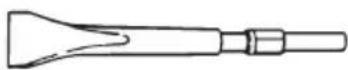
(1)
Cutter
○ Hammer grease A
500 g (in a can)
70 g (in a green tube)
30 g (in a green tube)
○ Groove digging and edging (Hammering)

(1) Cold chisel
Overall length: 280, 450 mm
○ Syringe (for chip removal)
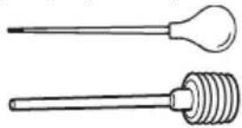
natural_image
Two types of medical or laboratory instruments: a pipette and a coiled spring, shown without any text or symbols.APPLICATIONS
○ Drilling holes in concrete
○ Drilling anchor holes
○ Demolishing concrete, chipping, digging, and squaring (by applying optional accessories)
PRIOR TO OPERATION
- Power source
Ensure that the power source to be utilized conforms to the power requirements specified on the product nameplate.
- Power switch
Ensure that the power switch is in the OFF position. If the plug is connected to a power receptacle while the power switch is in the ON position, the power tool will start operating immediately, which could cause a serious accident.
- Extension cord
When the work area is removed from the power source, use an extension cord of sufficient thickness and rated capacity. The extension cord should be kept as short as practicable.
English
4. How to install tool
NOTE
For tools such as a bull point and a cold chisel, use only Hitachi genuine parts.
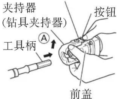
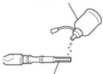
(1) Clean, then smear the tool shank with the grease or machine oil (Fig. 1).
(2) Press the push button, slightly lift the tool retainer in the direction of arrow Ⓐ as shown in Fig. 2 to hook the tool retainer edge with the push button and engage the push button.
(3) Release your finger from the push button and further lift the tool retainer in the direction of arrow Ⓐ.
NOTE
First time when the tool retainer is lifted, remove your finger from the push button. If the push button is kept pressed, the edge of the tool retainer comes in contact with your finger and the tool retainer cannot be lifted.
(4) Fully insert the tool shank into the hexagonal hole in the front cover.
(5) Return the tool retainer to secure the tool.
(6) Pull the tool to make sure it is locked completely.
NOTE
Remove in the reverse order of installation.
Grease or machine oil
natural_image
Diagram showing a bottle pouring liquid into a tool, with no visible text or symbolsTool shank
Fig. 1
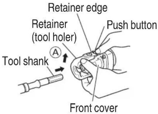
Fig. 2
WHEN THE PUSH BUTTON DOES NOT OPERATE SMOOTHLY
When the push button does not operate smoothly, please remove dirt from the inside through the outlet using a wire, etc. Then lubricate lubricating oil and push the push button several times to make it operate smoothly. (Fig. 3)
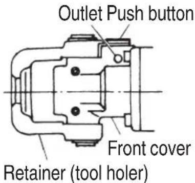
Fig. 3
HOW TO USE THE ROTARY HAMMER
NOTE
Ensure that the wing bolt in the side handle is properly tightened before using the tool.
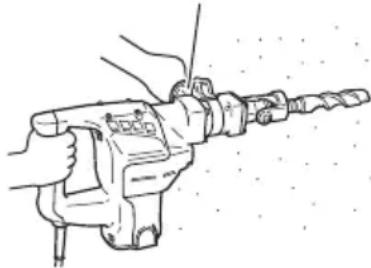
- How to drill holes (Fig. 4)
(1) Pull the switch trigger after applying the drill bit tip to the drilling position.
(2) It is unnecessary to forcibly press the rotary hammer main body. It is sufficient to slightly press the rotary hammer to an extent that shavings are freely discharged.
Side handle
natural_image
Line drawing of a hand operating a drill bit with a drill bit being inserted (no text or symbols present)Fig. 4
CAUTION
Although this machine is equipped with a safety clutch, if the drill bit becomes bound in concrete or other material, the resultant stoppage of the drill bit could cause the machine body to turn in reaction. Ensure that the main handle and side handle are gripped firmly during operation.
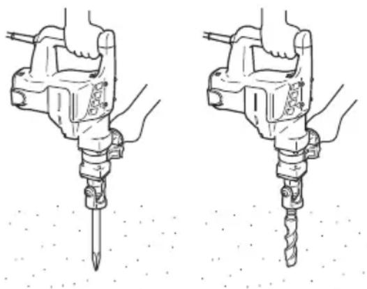
- How to chisel or demolish (Fig. 5)
By applying the drill bit tip to the chiseling or demolishing position, operate the rotary hammer by utilizing its empty weight.
Forcible pressing or thrusting is unnecessary.
- Warming up (Fig. 6)
The grease lubrication system in this unit may require warming up in cold regions.
Position the end of the bit so makes contact with the concrete, turn on the switch and perform the warming up operation. Make sure that a hitting sound is produced and then use the unit.
natural_image
Illustration of two hands using a drill bit to measure a drill bit (no text or symbols present)Fig. 5 Fig. 6
CAUTION
When the warming up operation is performed, hold the side handle and the main body securely with both hands to maintain a secure grip and be careful not to twist your body by the jammed drill bit.
DRILLING AND DRIVING-IN OPERATIONS FOR ANCHORS
Use the optional accessories for anchors, such as anchor adapter and taper shank adapter.
- When a rotation hammering anchor adapter is used.
(1) Install the self-drilling anchor in the anchor adapter (Fig. 7).
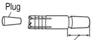
Snap off this portion after driving in the self-drilling anchor.
Fig. 7
English
(2) Turn ON the switch and drill a base hole with the self-drilling anchor. (Fig. 8)
At the start of the hole-drilling slightly tilt the rotary hammer to determine the hole position.
(3) After cleaning out dust with a syringe, attach the plug to the anchor tip and drive in the anchor with a manual hammer.
(4) After driving in the anchor, use the drift key to separate the anchor. (Fig. 9)
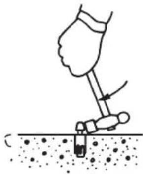
(5) By employing a manual hammer or pliers, snap off the tapered portion of the anchor. (Fig. 10)
CAUTION
Since the snapped-off tapered portion will fly about, pay attention to the snapping direction.
- When a taper shank adapter is used. (Fig. 11)
(1) Install drill bit with taper shank in the taper shank adapter.
(2) Turn the power on and drill a base hole to the depth sounded by indicating groove on the drill bit.
(3) After cleaning out dust with a syringe, attach the plug to the anchor tip and drive in the anchor with a manual hammer.
(4) To remove the drill bit (taper shank), insert the cotter into the slot of the taper shank adapter and strike the head of the cotter with a manual hammer supporting on a rest. (Fig. 12)
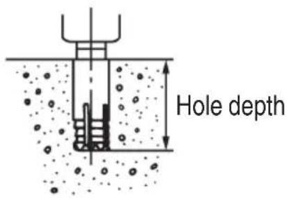
Fig. 8
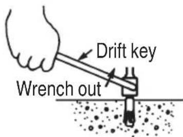
Fig. 9
natural_image
Illustration of a hand using a tool to dig or press over a surface with dots (no text or symbols)Fig. 10
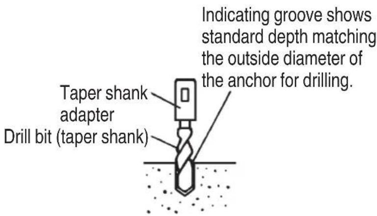
Fig. 11
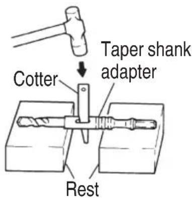
Fig. 12
HOW TO HANDLE A CORE BIT
When a core bit is used, large diameter holes and blind holes can be drilled. In this case, use optional accessories for core bits (such as a center pin and core bit shank) for more efficient operation.
1. Mounting
CAUTION
Prior to mounting a core bit, always disconnect the plug from the power supply receptacle.
(1) Mount the core bit on the core bit shank. (Fig. 13)
Before that, feed oil to the screw portion of core bit shank for easy dismounting.
(2) Mount the core bit shank on the main body in the same manner as in mounting the drill bit and the bull point. (Fig. 14)
(3) Insert the center pin into the guide plate until it reaches the extremity.
(4) Fit in the guide plate by aligning its concaved portion with the core bit tip. When the position of the concave is shifted by turning the guide plate right or left, the guide plate never slips off even when the drill is used in a downward direction. (Fig. 15)
2. Drilling holes
(1) Insert the plug into a receptacle.
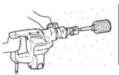
(2) A spring is built in the center pin. By straightly and gently pressing it to the wall or floor surface, the entire surface of the core bit tip attains contact to start the hole drilling job. (Fig. 16)
(3) When the hole depth reaches approximately 5 mm, the hole position can be determined. Then remove the center pin and guide plate from the core bit and continue the hole drilling job.
CAUTION
When removing the center pin and guide plate, always disconnect the plug from the receptacle.
3. How to dismount the core bit
Remove the core bit shank from the rotary hammer, hold the core bit with one hand, and strongly strike the head of the hexagonal portion of the core bit shank with a manual hammer two or three times, whereby the round head screw is loosened and the rotary hammer is ready for disassembly. (Fig. 17)
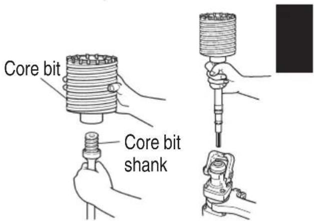
Fig. 14 Fig. 13
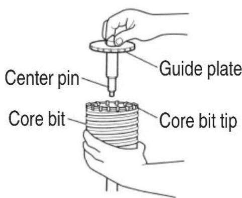
Fig. 15
natural_image
Line drawing of a hand operating a drill bit with a threaded shaft (no text or symbols)Fig. 16
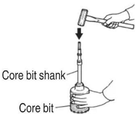
Fig. 17
HOW TO REPLACE GREASE
This machine is of full air-tight construction to protect against dust and to prevent lubricant leakage. Therefore, the machine can be used without lubrication for long periods. Replace the grease as described below.
1. Grease replacement period
After purchase, replace grease after every 6 months of usage. Ask for grease replacement at the nearest Hitachi authorized Service center. Proceed for replacement of grease.
2. Grease replenishment
CAUTION
Before replenishing the grease, turn the power off and pull out the power plug.
(1) Remove the crank cover and wipe off the grease inside. (Fig. 18)
(2) Supply 30g of Hitachi Electric Hammer Grease A (Standard accessory, contained in tube) to the crank case.
(3) After replenishing the grease, install the crank cover securely.
NOTE
The Hitachi Electric Hammer Grease A is of the low viscosity type. If necessary purchase from an Hitachi authorized Service center.
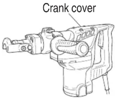
Fig. 18
MAINTENANCE AND INSPECTION
1. Inspecting the tool
Since use of a dull tool will degrade efficiency and cause possible motor malfunction, sharpen or replace the tool as soon as abrasion is noted.
2. Inspecting the mounting screws:
Regularly inspect all mounting screws and ensure that they are properly tightened. Should any of the screws be loose, retighten them immediately. Failure to do so could result in serious hazard.
3. Maintenance of the motor
The motor unit winding is the very “heart” of the power tool. Exercise due care to ensure the winding does not become damaged and/or wet with oil or water.
4. Inspecting the carbon brushes (Fig. 19)
The Motor employs carbon brushes which are consumable parts. When they become worn to or near the “wear limit”, it could result in motor trouble. When an auto-stop carbon brush is equipped, the motor will stop automatically. At that time, replace both carbon brushes with new ones which have the same carbon brush
Numbers shown in the figure. In addition, always keep carbon brushes clean and ensure that they slide freely within the brush holders.
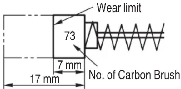
Fig. 19
5. Replacing carbon brushes
Loosen the two set screws and remove the tail cover. Remove the brush caps and carbon brushes. After replacing the carbon brushes, tighten the brush caps securely and install the tail cover with securely tightening two set screws.
6. Service parts list
CAUTION
Repair, modification and inspection of Hitachi Power Tools must be carried out by a Hitachi Authorized Service Center.
This Parts List will be helpful if presented with the tool to the Hitachi Authorized Service Center when requesting repair or other maintenance.
In the operation and maintenance of power tools, the safety regulations and standards prescribed in each country must be observed.
● Power supply cable
In case you need replacing of power supply cable, use the heavy polychloroprene sheathed fl exible cable 245IEC66 (YCW) or equivalent.
SERVICE PARTS LIST
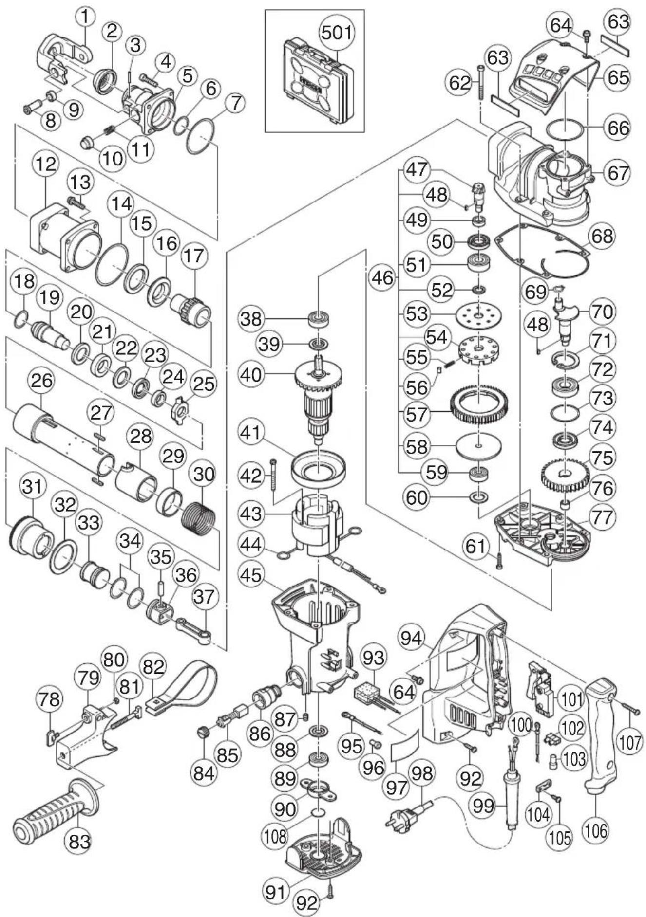
| Item No. | Code No. | No. Used | Remarks |
| 1 | 331241 | 1 | |
| 2 | 331243 | 1 | |
| 3 | 991697 | 2 D4×20 | |
| 4 | 981942 | 4 M6×25 | |
| 5 | 331238 | 1 | |
| 6 | 319572 | 1 S-25 | |
| 7 | 331244 | 1 | |
| 8 | 331242 | 2 | |
| 9 | 990134 | 2 | |
| 10 | 331240 | 1 | |
| 11 | 331239 | 1 | |
| 12 | 331237 | 1 | |
| 13 | 991712 | 4 M6×25 | |
| 14 | 956996 | 1 1AS-60 | |
| 15 | 321843 | 1 | |
| 16 | 331236 | 1 | |
| 17 | 331222 | 1 | |
| 18 | 313396 | 1 | |
| 19 | 331223 | 1 | |
| 20 | 331224 | 1 | |
| 21 | 321835 | 1 | |
| 22 | 331225 | 1 | |
| 23 | 331227 | 1 | |
| 24 | 321832 | 1 | |
| 25 | 331228 | 1 | |
| 26 | 331226 | 1 | |
| 27 | 331232 | 2 | |
| 28 | 331230 | 1 | |
| 29 | 331229 | 1 | |
| 30 | 331231 | 1 | |
| 31 | 331233 | 1 | |
| 32 | 331234 | 1 | |
| 33 | 331235 | 1 | |
| 34 | 986104 | 2 | |
| 35 | 331221 | 1 | |
| 36 | 326369 | 1 | |
| 37 | 321285 | 1 | |
| 38 | 6201DD | 1 6201DDCMPS2L | |
| 39 | 325003 | 1 | |
| 40 | 360875E | 1 220V-230V |
| Item No. | Code No. | No. Used | Remarks |
| 41 | 331252 | 1 | |
| 42 | 953174 | 2 D5×55 | |
| 43 | 340753E | 1 220V-230V “44” | |
| 44 | 930703 | 2 | |
| 45 | 331251 | 1 “86, 87” | |
| 46 | 331210 | 1 “47-49, 51-59” | |
| 47 | 331211 | 1 | |
| 48 | 944109 | 2 3×3×8 | |
| 49 | 331212 | 1 | |
| 50 | 313050 | 1 | |
| 51 | 6002DD | 1 6002DDCMPS2L | |
| 52 | 331213 | 1 | |
| 53 | 331214 | 1 | |
| 54 | 321281 | 1 | |
| 55 | 331218 | 10 | |
| 56 | 331217 | 10 | |
| 57 | 331215 | 1 | |
| 58 | 331219 | 1 | |
| 59 | 629VVM | 1 629VVC2PS2L | |
| 60 | 331220 | 1 | |
| 61 | 992803 | 2 M6×20 | |
| 62 | 986940 | 4 M6×45 | |
| 63 | ———2 | ||
| 64 | 994192 | 6 M5×16 | |
| 65 | 331245 | 1 | |
| 66 | 878713 | 1 | |
| 67 | 331207 | 1 | |
| 68 | 331549 | 1 | |
| 69 | 939540 | 1 | |
| 70 | 331208 | 1 | |
| 71 | 948391 | 1 | |
| 72 | 6203DD | 1 6203DDCMPS2L | |
| 73 | 996363 | 1 S-40 | |
| 74 | 321274 | 1 | |
| 75 | 331209 | 1 | |
| 76 | 939299 | 1 M661 | |
| 77 | 331253 | 1 | |
| 78 | 307947 | 1 M6×12 | |
| 79 | 331248 | 1 | |
| 80 | 949556 | 1 M6 | |
English
| Item No. | Code No. | No. Used | Remarks |
| 81 | 331247 1 | ||
| 82 | 331246 1 | ||
| 83 | 330209 1 | ||
| 84 | 945161 2 | ||
| 85 | 999043 2 | ||
| 86 | 958900 2 | ||
| 87 | 938477 2 M5×8 | ||
| 88 | 982631 1 | ||
| 89 | 608VVM 1 608VVC2PS2L | ||
| 90 | 331254 1 | ||
| 91 | 331202 1 | ||
| 92 | 302089 4 D5×20 | ||
| 93 | 331203 1 | ||
| 94 | 331204 1 | ||
| 95 | 330216 1 270L | ||
| 96 | 959141 1 | ||
| 97 | ——1 | ||
| 98 | 500457Z 1 | ||
| 99 | 940778 1 D10.7 | ||
| 100 | 981974 1 | ||
| 101 | 313093 1 | ||
| 102 | 938307 1 | ||
| 103 | 959141 1 | ||
| 104 | 960266 1 | ||
| 105 | 984750 2 D4×16 | ||
| 106 | 331205 1 | ||
| 107 | 307028 2 D4×25 | ||
| 108 | 331547 1 | ||
| 501 | 331206 1 |
natural_image
Line drawing of a quill pen in an inkwell (no text or symbols)服务中心
日立工机商业(中国)有限公司
- 目次
- 电动工具通用安全警告
- 警告!
- 用途
- 注意!
- 更换润滑油
- CONTENTS
- GENERAL POWER TOOL SAFETY WARNINGS
- WARNING
- English
- CAUTION
- ROTARY HAMMER SAFETY WARNINGS
- SYMBOL
- STANDARD ACCESSORIES
- OPTIONAL ACCESSORIES (sold separately)
- NOTE
- APPLICATIONS
- PRIOR TO OPERATION
- How to install tool
- WHEN THE PUSH BUTTON DOES NOT OPERATE SMOOTHLY
- HOW TO USE THE ROTARY HAMMER
- DRILLING AND DRIVING-IN OPERATIONS FOR ANCHORS
- HOW TO HANDLE A CORE BIT
- Mounting
- Drilling holes
- How to dismount the core bit
- HOW TO REPLACE GREASE
- Grease replacement period
- Grease replenishment
- MAINTENANCE AND INSPECTION
- Inspecting the tool
- Inspecting the mounting screws:
- Maintenance of the motor
- Inspecting the carbon brushes (Fig. 19)
- Replacing carbon brushes
- Service parts list
- ● Power supply cable
- SERVICE PARTS LIST
Brand : HiKOKI
Model : DH38SS
Category : Rotary hammer