
W-ClearPass - Uncategorized DELL - Free user manual and instructions
Find the device manual for free W-ClearPass DELL in PDF.


| Product Type | Network Access Control (NAC) Appliance |
| Model | Dell W-ClearPass (rebranded Aruba ClearPass) |
| Form Factor | 1U Rackmount |
| Dimensions (H x W x D) | 4.3 cm x 43.5 cm x 50.8 cm (1.7 in x 17.1 in x 20 in) |
| Weight | 10.5 kg (23.1 lb) |
| Power Supply | Dual 460W AC power supplies (redundant) |
| Input Voltage | 100-240V AC, 50-60 Hz |
| Typical Power Consumption | 150W |
| Processor | Intel Xeon D-1520 (4 cores, 2.2 GHz) |
| Memory | 16 GB DDR4 ECC RAM (up to 64 GB) |
| Storage | 240 GB SSD (RAID 1 optional) |
| Network Interfaces | 4x 1GbE RJ45, 2x 10GbE SFP+ |
| Management Port | 1x dedicated 1GbE RJ45 |
| USB Ports | 2x USB 3.0 |
| Console Port | 1x RJ45 serial console |
| Operating Temperature | 0°C to 40°C (32°F to 104°F) |
| Humidity | 10% to 80% non-condensing |
| Key Functions | Authentication, authorization, accounting (AAA), guest management, endpoint compliance, policy management |
| Wireless Support | Aruba, Cisco, Ruckus, and other standards-based APs |
| Maintenance | Clean with dry cloth; keep vents free of dust; update firmware via web interface |
| Safety | Use grounded power outlet; avoid liquids; do not block vents |
| Spare Parts | Hot-swappable power supplies and fans; SSD replacement |
| Repairability | Field-replaceable components; no user-serviceable internal parts beyond approved replacements |
| Regulatory Compliance | FCC, CE, RoHS, UL |
| Included Accessories | Rack mount kit, power cords, console cable, quick start guide |
Frequently Asked Questions - W-ClearPass DELL
User questions about W-ClearPass DELL
0 question about this device. Answer the ones you know or ask your own.
Ask a new question about this device
Download the instructions for your Uncategorized in PDF format for free! Find your manual W-ClearPass - DELL and take your electronic device back in hand. On this page are published all the documents necessary for the use of your device. W-ClearPass by DELL.
USER MANUAL W-ClearPass DELL
Dell Networking W-ClearPass Policy Manager 6.6
Copyright Information
© Copyright 2017 Hewlett Packard Enterprise Development LP. Dell™, the DELL™ logo, and PowerConnect are trademarks of Dell Inc.
All rights reserved. Specifications in this manual are subject to change without notice.
Originated in the USA. All other trademarks are the property of their respective owners.
Open Source Code
This product includes code licensed under the GNU General Public License, the GNU Lesser General Public License, and/or certain other open source licenses. A complete machine-readable copy of the source code corresponding to such code is available upon request. This offer is valid to anyone in receipt of this info and shall expire three years following the date of the final distribution of this product version by Hewlett Packard Enterprise Company. To obtain such source code, send a check or money order in the amount \$10.00 to:
Hewlett-Packard Enterprise Company
Attn: General Counsel
3000 Hanover Street
Palo Alto, CA 94304
USA
Please specify the product and version for which you are requesting source code.
About W-ClearPass Policy Manager..21
About the W-ClearPass Access Management System.21....
About This Guide 21
Getting Started.21
W-ClearPass Access Management System Overview 22
Key Features.23
Advanced Policy Management 23
W-ClearPass Specifications 24
Accessing Configuration Information 29
Introduction 30
Start Here 30
Services 30
Authentication and Authorization 31
Identity 31
Posture 31
Enforcement 31
Network 31
Policy Simulation.... 31
Profile Settings 32
Importing and Exporting Information 32
Importing Information Into W-ClearPass 32
Exporting Information From W-ClearPass.... 33
Services 35
Services Architecture and Flow 35
Start Here: About Policy Manager Service Templates 36
Creating Templates for W-ClearPass Services 36
Service Templates Provided 38
Service Templates Supported for High Capacity Guest Mode 38
Viewing the List of Services 39
Viewing Existing Services.... 40
Adding and Removing Services 41
Reordering Services 44
Configuring Service Templates 46
802.1X Wired, 802.1X Wireless, and Dell 802.1X Wireless Service Template 46
Auto Sign-On Service Template 50
Dell VPN Access with Posture Checks Service Template 51
Certificate/Two-Factor Authentication for W-ClearPass Application Login Service Template..53
W-ClearPass Admin Access Service Template 55
W-ClearPass Admin SSO Login (SAML SP Service) Service Template.56
W-ClearPass Identity Provider (SAML IdP Service) Service Template 57
Device MAC Authentication Service Template 58....
EDUROAM Service Template 60
Encrypted Wireless Access via 802.1X Public PEAP Method Service Template.62....
Guest Access Service Template.... 63
Guest Access Web Login Service Template 65
Guest Authentication with MAC Caching Service Template 66
Guest Social Media Authentication Service Template.... 68
OAuth2 API User Access Service Template 70
Onboard Service Template 70
Configuring Policy Manager Services 72
802.1X Wired Service 72
802.1X Wired—Identity Only Service 73
Dell 802.1X Wireless Service 73
802.1X Wireless—Identity Only Service 84
Dell 802.1X Wireless Service 85
Cisco Web Authentication Proxy Service 95
MAC Authentication Service 96
RADIUS Authorization Service 97
RADIUS Enforcement (Generic) Service 98
RADIUS Proxy Service 98
Dell W-Series Application Authentication Service 99
Dell W-Series Application Authorization Service 100
W-ClearPass OnConnect Enforcement Service 100
Event-Based Enforcement Service.... 102
TACACS+ Enforcement Service 104
Web-Based Authentication Service 107
Web-based Health Check Only Service.... 111
Web-Based Open Network Access Service 116
Monitoring 117
Live Monitoring: Access Tracker 117
About the Access Tracker.... 117
Customizing the Access Tracker.... 118
Viewing Access Tracker Session Details 120
Live Monitoring: Accounting 129
Modifying the Accounting Page Parameters.... 130
RADIUS Accounting Details > Summary Tab 131
RADIUS Accounting Record Details > Auth Sessions.Tab 133
RADIUS Accounting Record Details > Utilization_Tab 134
RADIUS Accounting Record Details > Details.Tab 135
TACACS+ Accounting Record Details > Request.Tab.137....
TACACS+ Accounting Record Details > Auth Sessions Tab 138
TACACS+ Accounting Record Details > Details..Tab..139....
Live Monitoring: OnGuard Activity 140
About OnGuard Activity.140
Bouncing an Agent Using Non-SNMP 141
Bouncing a Client Using SNMP.144
Broadcasting a Message to Active Endpoints.145....
Sending a Message to Selected Endpoints 146
Live Monitoring: Analysis and Trending 146
Live Monitoring: System Monitor 147
System Monitor Page 148
Process Monitor Page 149
Network Monitor Page 150
ClearPass Monitor Page 151
Profiler and Discovery 151
Profiler and Discovery: Endpoint Profiler 152
Profiler and Discovery: Network Discovery 153
About Network Discovery.... 153
Adding the Configurations to Query Seed Devices 154
SNMP Credentials Configuration 154
SSH Credentials Configuration 156
WMI Credentials Configuration.... 158
Initiating a Network Discovery Scan.... 160
About Auto-Refresh 162
Importing and Viewing Discovered Network Devices 162
Viewing Discovered Endpoints.... 165
Configuring Nmap-Based Endpoint Port Scans 166
Audit Viewer 167
Introduction 167
Add Events.... 167
Modify Events.... 168
Remove Events 169
Event Viewer 169
About the Event Viewer.... 170
Creating an Event Viewer Report Using Default Values 171
Creating an Event Viewer Report Using Custom Values 171
Viewing Report Details 172
Data Filters 172
About Data Filters 172
Adding a Data Filter 174
Restoring Blacklisted Users to the Network 177
Authentication Methods and Sources 179
Supported Authentication Methods 179
Tunneled EAP Authentication Methods..179.
Non-Tunneled Authentication Methods.179.
Authentication and Authorization Architecture and Flow.179.
Configuring Authentication Methods for an Existing Service 181.
Adding and Configuring Authentication Methods..183.
Adding a New Authentication Method.... 183
Modifying an Existing Authentication Method 185
Authorize Authentication Method 185
CHAP Authentication Method.... 186
EAP-FAST Authentication Method 187
EAP-GTC Authentication Method.... 192
EAP-MSCHAPv2 193
EAP-PEAP 194
EAP-PEAP-Public 196
EAP-PWD 199
EAP-TLS 200
EAP-TTLS 202
MAC-AUTH Authentication Method 204
MSCHAP 205
PAP 206
Adding and Configuring Authentication Sources 207
Generic LDAP and Active Directory 208
Generic SQL DB 222
HTTP 227
Kerberos 232
Okta 235
RADIUS Server 240
Adding a Static Host List as an Authentication Source 243
About Static Host Lists 243
Adding a Static Host List as an Authentication Source 244
Token Server 245
Configuring Identity Settings 249
Configuring Single Sign-On 249
SAML Service Provider (SP) Configuration 249
SAML Identity Provider (IdP) Configuration 251
Managing Local Users 252
Adding a Local User 252
Modifying a Local User Account 254
Importing and Exporting Local Users 255
Setting Password Policy for Local Users 255
Disabling Local User Accounts 257
Adding and Modifying Endpoints 259
Viewing the List of Authentication Endpoints 259
Viewing Endpoint Authentication Details.260....
Performing Bulk Updates of Endpoint Attributes 260
Triggering Actions to Be Performed on Endpoints 261.
Updating Device Fingerprints From a Hosted Portal 262
Manually Adding an Endpoint.263....
Modifying an Endpoint 264
Managing Static Host Lists 268
About Static Host Lists 268
Adding a Static Host List 269
Static Hosts Lists Configuration Summary 271
Editing a Static Host List 271
Importing and Exporting Static Host Lists 272
Configuring a Role and Role-Mapping Policy 272
Preconfigured Roles 272
Identity Roles Architecture and Workflow 273
Adding and Modifying Roles 274
Adding and Modifying Role-Mapping Policies 275
Posture Architecture and Flow 279
Posture Policy 279
Audit Servers 279
Assessing Client Consistency 280
Application Token 280
System Token 281
Unified Agent System Tray Status Icons 281
About the Unified Agent 281
Unified Agent System Tray Icons 281
OnGuard-Only System Tray Icons 283
Creating a New Posture Policy 283
About W-ClearPass Posture Policies 283
Creating a New Posture Policy 284
Configuring Posture Policy Agents and Hosts 285
Introduction 285
NAP Agent Posture Plug-ins 286
OnGuard Agent Posture Plug-ins 286
Configuring Posture Policy Plug-ins 288
Configuring OnGuard Agent Plugins 289
Configuring NAP Agent Plugins 348
Configuring Posture Policy Rules 352
Configuring Posture for Services 353
Configuring Audit Servers 355
Posture 279
Audit Service Flow Control 355
Default Audit Servers 356
Custom Audit Servers 359
Post-Audit Rules 368
Configuring Enforcement Policies and Profiles 371
Configuring Enforcement Policies 371
Configuring Enforcement Profile.373.
Adding an Enforcement Profile 374
Modifying an Existing Enforcement Profile 376
Agent Enforcement Profile 376
Agent Script Enforcement Profile 379
Dell Downloadable Role Enforcement Profile 383
Dell RADIUS Enforcement Profile 393
Cisco Downloadable ACL Enforcement Profile 395
Cisco Web Authentication Enforcement Profile 397
W-ClearPass Entity Update Enforcement Profile 399
CLI-Based Enforcement Profile 401
Filter ID Based Enforcement Profile 403
Generic Application Enforcement Profile 405
HTTP Based Enforcement Profile 406
RADIUS Based Enforcement Profile 407
RADIUS Change of Authorization (CoA) Profile 409
Session Notification Enforcement Profile 411
Session Restrictions Enforcement Profile 413
SNMP-Based Enforcement Profile 418
TACACS+ Based Enforcement Profile 419
VLAN Enforcement Profile 422
Configuring Policy Simulation 425
Active Directory Authentication Simulation 425
Adding an Active Directory Simulation 426
Viewing the Simulation Results 426
Application Authentication Simulation 427
Simulation Tab 427
Attributes Tab 427
Results tab 428
Audit Simulation 428
Results Tab 429
Chained Simulation 430
Simulation Tab 430
Attributes Tab 430
Results Tab 432
Enforcement Policy Simulation 432
Simulation Tab 433
Attributes tab 434
Results Tab 435
RADIUS Authentication Simulation 436
Adding a RADIUS Authentication Simulation 436
Setting the Attributes to Be Tested 438
Viewing the Simulation Results 440
Role Mapping Simulation 441
Simulation Tab 441
Attributes Tab 442
Results Tab 443
Service Categorization Simulation 444
Simulation Tab 444
Attributes Tab 444
Results Tab 445
Import and Export Simulations 446
W-ClearPass Policy Manager Profile 447
W-ClearPass Profile Overview 447
Introduction 447
Enabling Endpoint Classification.... 447
Configuring CoA for an Endpoint-Connected Device 448
How W-ClearPass Profile Classifies Endpoints 449
Fingerprint Dictionaries 450
Viewing Live Endpoint Information for a Specific Device 451
About the Device Profile 452
Endpoint Information Collectors 452
DHCP Collector 453
NetFlow Collector 453
W-ClearPass Onboard Collector 453
HTTP User-Agent Strings Collector 453
MAC OUI Collector 454
ActiveSync Plug-in Collector 454
W-ClearPass OnGuard Agent 454
SNMP Collector 454
About the Subnet Scan Collector 457
Configuring Subnet Scans 457
SNMP Configuration for Wired Network Profiling 459
Accessing SSH and WMI Configuration Information 461
Network Access Devices 463
Introduction 463
Adding and Modifying Network Devices 464
Adding a Network Device 464
Adding and Modifying Proxy Targets 473
Adding a Proxy Target 473
Adding and Modifying Device Groups 474
Configuring the Ingress Event Sources 476
Administration 479
W-ClearPass Guest Portal 480
Managing Admin Users.481
Changing the Administration Password 481
Adding an Admin User.482
Importing and Exporting Admin Users 483
Setting Password Policy for Admin Users 483
Disabling Admin User Accounts 485
Managing Admin Privileges.
Overview 486
Defining Custom Admin Privileges 486
Creating Custom Administrator Privileges 489
Administrator Privilege XML File Structure 489
Administrator Privileges and Task IDs 489
Sample Administrator Privilege XML File 493
Server Configuration 494
Editing Server Configuration Settings 495
Cluster-Related Options 496
Modifying W-ClearPass Server Settings 496
Configuration Tasks for Disabled Nodes in a Cluster 496
Server Configuration Cluster Options 537
Synchronizing the Cluster Date and Time with the NTP Server 537
Changing the Cluster-Wide Password 540
Managing Policy Manager Zones
About Policy Manager Zones 541
Adding Policy Manager Zones 541
Mapping Policy Manager Zones 542
Configuring NetEvents Targets 543
Configuring Virtual IP Settings 545
Clearing Machine Authentication Cache 545
Making a Subscriber Node 546
Cluster-Wide Parameters 547
Collecting Logs 562
Backing Up the Policy Manager Database 563
Restoring Policy Manager Configuration Data 564
Performing a System Cleanup 565
Shutting Down or Rebooting the Server 566
Dropping a Subscriber Node 567
Log Configuration 567
Service Log Configuration 567
System Level Configuration 569
Downloading Local Shared Folders 570
License Management 571
About License Usage Limits.571....
Managing Licenses.572
Adding an Application License 573.
Activating a Server License 574
Activating an Application License 576....
Updating a Server License 579
Updating an Application License 580
SNMP Trap Receivers 581
SNMP Trap Receivers Main Page 582
Adding an SNMP Trap Server 582
Importing an SNMP Trap Server 584
Exporting All SNMP Trap Servers 585
Exporting an SNMP Trap Server 586
Deleting an SNMP Trap Server 587
Syslog Targets 587
Syslog Targets Main Page 587
Adding a Syslog Target 588
Importing a Syslog Target 589
Exporting All Syslog Target 590
Exporting a Syslog Target 590
Deleting a Syslog Target 591
Syslog Export Filters 591
About Syslog Export Filters 591
Syslog Export Filters Page 592
Adding a Syslog Export Filter 592
Importing a Syslog Filter 601
Exporting All Syslog Filter 602
Exporting a Syslog Filter 602
Deleting a Syslog Filter 603
Messaging Setup 603
Configuring Messaging 603
Sending a Test Email Message 604
Sending a Test SMS Message.... 605
Endpoint Context Servers 606
Introduction 606
Endpoint Context Servers Page 606
Adding an Endpoint Context Server.... 607
Importing an Endpoint Context Server 609
Exporting All Endpoint Context Servers 610
Modifying an Endpoint Context Server 611
Polling an Endpoint Context Server.... 613
Deleting an Endpoint Context Server 613
Configuring Endpoint Context Server Actions 614.
Filtering an Endpoint Context Server Action Report 6.14
Configuring Endpoint Context Server Actions.6.1.4
Adding machine-os and host-type Endpoint Attributes 618....
Adding Vendor-Specific Endpoint Context Servers 619
Adding an AirWatch Endpoint Context Server.620....
Adding an AirWave Endpoint Context Server 622
Adding an Aruba Activate Endpoint Context Server 624
Adding a ClearPass Cloud Proxy Endpoint Context Server 626
Adding a Google Admin Console Endpoint Context Server 627
Adding a Generic HTTP Endpoint Context Server 629
Integrating W-ClearPass with Infoblox 630
Integrating W-ClearPass with Juniper Networks SRX 645
Adding aJAMF Endpoint Context Server 655
Adding a MaaS360 Endpoint Context Server 656
Adding a MobileIron Endpoint Context Server 659
Adding a Palo Alto Networks Firewall Endpoint Context Server 661
Adding a Palo Alto Networks Panorama Endpoint Context Server 663
Adding an SAP Afaria Endpoint Context Server 664
Adding aSOTI Endpoint Context Server 666
Adding a XenMobile Endpoint Context Server 668
File Backup Servers 669
Server Certificates 671
Server Certificate Page 671
Server Certificate Type 672
Creating a Certificate Signing Request 674
Creating and Installing a Self-Signed Certificate 676
Importing a Server Certificate 679
Exporting a Server Certificate 680
Certificate Trust List 681
Certificate Trust List Main Page 681
Adding a Certificate 682
Viewing a Certificate Detail 682
Deleting a Certificate 682
Certificate Revocation Lists 683
About Certificate Revocation Lists 683
Updating All Certificate Revocation Lists 683
Adding a Certificate Revocation List 683
Deleting a Certificate Revocation List 684
RADIUS Dictionary 685
Import RADIUS Dictionary 686
TACACS+ Services Dictionary 686
Device Fingerprints Dictionary 688
Dictionary Attributes 689
Introduction .689....
Adding a Dictionary Attribute 690....
Modifying Dictionary Attributes 691....
Importing Dictionary Attributes 691
Exporting All Dictionary Attributes.692
Exporting Selected Dictionary Attributes.693.
Software Updates and OnGuard Settings 693
Software Updates 693
About Software Updates.694
Software Updates Page 694
Install Update Dialog Box 696
Reinstalling a Patch 698
Uninstalling a Skin 698
OnGuard Settings and OnGuard Custom Web Pages 699
Introduction 699
About the OnGuard Custom Interface and the Remediation Process 699
Configuring OnGuard Settings.... 700
Creating OnGuard Custom Web Pages 702
OnGuard Global Agent Settings 708
About Global Agent Settings 708
Global Agent Settings Parameters for OnGuard Agents 709
Global Agent Settings: Run OnGuard As Parameter 710
Using W-ClearPass Dictionaries 711
Cluster Upgrade/Update Tool 713
About the Cluster Update Tool 713
About the Cluster Update Feature 713
Before Updating the Cluster 714
Updating the Cluster 714
Viewing Update Status.... 716
About the Cluster Upgrade Tool 718
Introduction .719
Cluster Upgrade Process Overview 719
Before You Upgrade.... 719
Installing the Cluster Upgrade Tool 720
Launching the Cluster Upgrade Tool 721
Upgrading the W-ClearPass Cluster 723
Viewing Upgrade Status 726
Steps in the Upgrade Tool's Automated Workflow 727
Sample Times Required for Upgrade 728
Troubleshooting Tips 728
Configuring Processing for Ingress Events 731
Overview 731
Enabling Ingress Event Dictionaries..731.
Configuring the Ingress Event Sources.732.
Configuring the Ingress Receiving Ports.734.
Configuring an Event-Based Enforcement Service 734
Introduction 734
Adding an Event-Based Enforcement Service 735
Associating the Enforcement Service with an Enforcement Policy 735
Enabling Ingress Events Processing 736
OnGuard Dissolvable and Native Agents 739
Introduction 739
Accessing the OnGuard Support Charts.739.
Upgrading From OnGuard Plugin Version 1.0 to 2.0 740
Overview 740
Creating a New Enforcement Profile to Set the SDKType 740
Modifying an Existing Enforcement Policy for OnGuard Plugin_v2.0 742
Creating a New Posture Policy for OnGuard Plugin v2.0 Agents 743
Creating a WebAuth Service for OnGuard Plugin v2.0 Agents 747
Important Points 748
Native Agents Only Mode 749
Configuring Workflow in Native Agents Only Mode 749
End-to-End Flow in Native Agents Only Mode 750
Native Agents with Java Fallback Mode 754
Configuring Native Agents with Java Fallback Mode 754
End-to-End Flow in Native Agents with Java Fallback Mode 755
Configuring Web Agent Flow - Java Only Mode 755
Configuring Web Agent Flow in W-ClearPass Policy Manager 755
Configuring Web Agent Flow in W-ClearPass Guest 756
Native Dissolvable Agent Supported Operating Systems and Browsers 759
OnGuard Dissolvable Agent Supported Browsers and Java Versions 762
W-ClearPass Insight Reports 769
About W-ClearPass Insight 769
Introduction 769
Enabling Insight and Specifying a Master Insight Node 770
Launching Insight 771
About the Insight Dashboard 772
Dashboard Overview 772
Adding a Report Widget to the Dashboard Landing Page 773
Removing a Report Widget from the Dashboard Landing Page 773
Creating a Report or Alert From the Dashboard 774
Specifying the Date Range for Data Collection 775
Authentication Dashboard 776
Endpoints Dashboard 777
Guest Dashboard 778
Network Dashboard.779....
Posture Dashboard 779
System Dashboard 780
System Monitor Dashboard 780
Searching the Insight Database 781
About Insight Search.782....
Search Example 782
Creating Alerts 783
Introduction 783
Creating New Alerts 784
Modifying the User Watchlist 785
Adding or Removing Users from the Watchlist 788
Creating Reports 789
Overview 790
Settings Configuration 791
Report Filters Configuration 793
Specifying the Logo and Branding 793
Report Summary Page 795
Configured Reports Page 796
Viewing Reports 796
Insight Report Categories Reference 798
Introduction 798
Authentication Category Reports 798
Endpoint Category Reports 801
Guest Authentication Category Reports 802
Network Category Reports 805
OnGuard Category Reports 806
Onboard Category Report 809
RADIUS Authentication Category Reports 810
System Category Reports 811
TACACS Category Reports 812
Administration Operations 813
Overview 813
File Transfer Settings Configuration 814
Testing File Transfer Configuration 815
Database Settings Configuration 816
Managing Insight Admin Privileges 817
Overview 817
Viewing the Default Insight Admin Privileges 817
Defining Custom Insight Admin Privileges 818
Insight UI Differences for Read-Only Users 820
Command Line Interface 821
Cluster Commands 821
cluster drop-subscriber.821....
cluster list 822
cluster make-publisher 822
cluster make-subscriber 822
cluster reset-database 823
cluster set-cluster-passwd 823
cluster sync-cluster-passwd 824
Configure Commands 824
configure date 824
configure dns 826
configure fips-mode 826
configure hostname 827
configure ip....827
configure ip6 828
configure mtu 828
configure timezone 830
Network Commands 830
network ip6 831
network ip 832
nslookup 833
network ping6 834
network ping 835
network reset 835
network traceroute6 836
network traceroute 836
Miscellaneous Commands 836
ad auth 837
ad netjoin 837
ad netleave 838
ad passwd-server 838
ad testjoin....839
alias 839
backup 840
dump certchain 841
dump logs....841
dump servercert 842
exit 842
help 842
krb auth 843
krb list 843
ldapsearch 843
quit 844
restore 844
Service Commands 845
service
Show Commands.847
show all-timezones 847
show date 847
show dns.848
show domain 848
show fipsmode 849
show hostname 849
show ip 849
show license 850
show ntp 851
show sysinfo....851
show timezone 851
show version 852
SSH Timed Account Lockout 852
Introduction 852
SSH Account Lockout Configuration 853
SSH Account Lockout Alerts 855
SSH Account Lockout Behavior 855
System Commands 856
system apps-access-reset 856
system boot-image 856
system cleanup 857
system create-api-client 858
system gen-recovery-key 858
system gen-support-key 858
system install-license 858
system morph-vm 859
system refresh-license 860
system reset-server-certificate 860
system restart 860
system shutdown....861
system sso-reset 861
system start-rasession.... 861
system status-rasession 862
system terminate-rasession.... 862
system update 862
system upgrade.863
SNMP Private MIB, SNMP Traps, System Events, Error Codes 867
W-ClearPass SNMP Private MJB 867
Introduction 867
System MIB Entries 867
RADIUS Server MIB Entries.868
Policy Server MIB Entries 869
Web Authentication Server MIB Entries 871
TACACS+ Server MIB Entries 871
Network Traffic MIB Entries 872
W-ClearPass SNMP Traps and OIDs 872
Introduction 873
W-ClearPass SNMP Traps 873
SNMP Trap Details 874
SNMP Daemon Traps 875
SNMP Daemon Trap Events 875
Network Interface up and Down Events 875
Network Interface Status Traps 875
W-ClearPass Processes Stop and Start Events 876
Disk Space Threshold Traps 876
Disk Utilization Threshold Exceed Events 876
Process Status Traps 876
CPU Load Average Exceed Events for 1, 5, and 15 Minute Thresholds 888
CPU Load Average Traps 888
Important System Events 889
Admin User Interface Events 889
Admin Server Events 890
Async Service Events 890
W-ClearPass/Domain Controller Events 890
W-ClearPass System Configuration Events 890
W-ClearPass Update Events 891
Cluster Events 891
Command Line Events 891
Database Replication Services Events 891
Licensing Events 892
Policy Server Events 892
RADIUS/TACACS+ Server Events 892
Service Names 892
SNMP Events 893
Support Shell Events 893
System Auxiliary Service Events 893
System Monitor Events 893
Error Codes 894
Use Cases 899
802.1X Wireless Use Case 899
Configuring a Service 900
Creating a New Role Mapping Policy 900
Web Based Authentication Use Case 905
Configuring a Service 905....
MAC Authentication Use Case 912
Configuring the Service 912
TACACS+ Use Case 915
Configuring the Service 916....
Single Port Use Case 917
Rules Editing and Namespaces 919
Namespaces 919
Application Namespace.... 920
Audit Namespaces 921
Authentication Namespaces 921
Authorization Namespaces 923
Certificate Namespaces.... 924
Connection Namespaces 925
Date Namespaces 926
Device Namespaces 926
Endpoint Namespaces.... 927
Guest User Namespaces 927
Host Namespaces 927
Local User Namespaces 927
Posture Namespaces 928
RADIUS Namespaces 928
TACACS Namespaces 929
Tips Namespaces 929
Variables 929
Operators 930
Applications Dictionaries 934
Viewing an Application Dictionary 934
Deleting an Application Dictionary.... 935
This chapter provides an overview of the W-ClearPass 6.6 Policy Manager Access Management System.
This chapter includes the following information:
- About the W-ClearPass Access Management System
• Using the Policy Manager Dashboard - Accessing Configuration Information
- Importing and Exporting Information
About the W-ClearPass Access Management System
This section contains the following information:
• About This Guide
• W-ClearPass Access Management System Overview
• Key Features
• Advanced Policy Management
• W-ClearPass Specifications
About This Guide
Welcome to the W-ClearPass Policy Manager 6.6 User Guide.
The W-ClearPass Policy Manager 6.6 User Guide provides a general overview of W-ClearPass Policy Manager features, as well as detailed descriptions of the configuration settings used to manage and monitor your Manager deployment.
Intended Audience
The intended audience for the W-ClearPass Policy Manager 6.6 User Guide includes customers, partners, and field Sales Engineers.
Please note that this document is not a training guide, and it is assumed that the reader has at minimum foundational training in W-ClearPass Essentials and, if possible, Dell Certified Professional (ACCP) certification
The user of this guide should have a working knowledge of the following:
• AAA technologies (RADIUS, TACACS, 802.1X, MAC address authentication, and Web authentication)
• Layer-2 and Layer-3 networking
- User Identity stores, such as Active Directory

Providing information about network device configurations and capabilities is outside the scope of this guide. For information on these topics, refer to the documentation provided by the vendor of your network equipment.
Getting Started
If you are new to W-ClearPass Policy Manager, refer to the following sections:
- For a general description of W-ClearPass Policy Manager features, refer to the following topics in this section, W-ClearPass Access Management System Overview and Key Features.
-
For a description of how to use the Dashboard, see Using the Policy Manager Dashboard on page 26.
-
For a list of common configuration tasks and pointers to information about how to perform each task, refer to Accessing Configuration Information on page 29.
- If you are planning a new W-ClearPass Policy Manager deployment, refer to the W-ClearPass Deployment Guide. The W-ClearPass Deployment Guide is organized in a way that presents the recommended sequence in which W-ClearPass deployment should take place, and makes the major deployment tasks easy to implement.
W-ClearPass Access Management System Overview
The W-ClearPass Policy Manager™ Access Management System provides a window into your network and covers all your access security requirements from a single platform. You get complete views of mobile data and users and have total control over what they can access.
With W-ClearPass, IT can centrally manage network policies, automatically configure devices and distribute security certificates, admit guest users, assess device health, and even share information with third-party solutions—through a single pane of glass, on any network and without changing the current infrastructure.
About Policies, Profiles, and Services
In W-ClearPass Policy Manager, a policy provides the rules that tells W-ClearPass when to execute profile: Profiles are actions that are taken by W-ClearPass; for example assigning a certain role to a user or ena command authorization for different types of users on a switch. The actions specified in a policy are the profiles to be activated when specific conditions or rules are met.
Then a policy is associated with a service—a service ties all the elements together: authentication sources, authorization sources, role-mapping, and enforcement policies.
Role-Based and Device-Based Access
The W-ClearPass Policy Manager platform provides role-based and device-based network access control fo employees, contractors, and guests across any wired, wireless, and VPN infrastructure.
W-ClearPass works with any multivendor network and can be extended to business and IT systems that already in place.
Self-Service Capabilities
W-ClearPass delivers a wide range of unique self-service capabilities. Users can securely onboard their own devices for enterprise use or register AirPlay, AirPrint, Digital Living Network Alliance (DLNA), and Universal and Play (UPnP) devices that are enabled for sharing, sponsor guest Wi-Fi access, and even set up sharing Apple TV and Google Chromecast.
Leveraging Contextual Data
The power of W-ClearPass comes from integrating ultra-scalable AAA (authentication, authorization, and accounting) with policy management, guest network access, device onboarding, and device health checks in a complete understanding of context.
From this single W-ClearPass policy and AAA platform, contextual data is leveraged across the network to ensure that users and devices are granted the appropriate access privileges.
W-ClearPass leverages a user's role, device, location, application use, and time of day to execute custom security policies, accelerate device deployments, and streamline network operations across wired networks wireless networks, and VPNs.
Third-Party Security and IT Systems
W-ClearPass can be extended to third-party security and IT systems using REST-based APIs to automate v flows that previously required manual IT intervention. W-ClearPass integrates with mobile device managen to leverage device inventory and posture information, which enables well-informed policy decisions.
Key Features
W-ClearPass's key features are as follows:
- Bring Your Own Device (BYOD) Certificate Authority for secure self service onboarding
• Auto Sign-On and single sign-on (SSO) support via Security Assertion Markup Language (SAML) v2.0 - Social network and Cloud application SSO via OAuth2, Facebook, Twitter, LinkedIn, Office365, Google Apps, and so on
- Enterprise reporting, monitoring, and alerting
• Role-based network access enforcement for multivendor Wi-Fi, wired, and VPN networks
• High performance, scalability, High Availability, and load balancing - A Web-based user interface that simplifies policy configuration and troubleshooting
- Network Access Control (NAC), Network Access Protection (NAP) posture and health checks, and Mobile Device Management (MDM) integration for mobile device posture checks
- Advanced reporting of all user authentications and failures
- HTTP/RESTful APIs for integration with third-party systems, Internet security, and MDM
• Device profiling and self-service onboarding - Guest access with extensive branding and customization and sponsor-based approvals
• IPv6 administration support
Advanced Policy Management
W-ClearPass advanced policy management support includes:
- Employee access
W-ClearPass offers user and device authentication based on 802.1X, non-802.1X, and Web Portal access methods. To strengthen security in any environment, you can concurrently use multiple authentication protocols, such as PEAP, EAP-FAST, EAP-TLS, EAP-TTLS, and EAP-PEAP-Public.
For fine-grained control, you can use attributes from multiple identity stores, such as Microsoft Active Directory, LDAP-compliant directory, Open Database Connectivity (ODBC)-compliant SQL database, token servers, and internal databases across domains within a single policy.
Additionally, you can add posture assessments and remediation to existing policies at any time.
• Device profiling
W-ClearPass provides a profiling service that discovers and classifies all endpoints, regardless of device You can obtain a variety of contextual data(such as MAC OUIs, DHCP fingerprinting, and other identity centric device data) and use this data within policies.
Stored profiling data identifies device profile changes and dynamically modifies authorization privileges. example, if a printer appears as a Windows laptop, W-ClearPass Policy Manager can automatically deny access.
- Access for unmanaged endpoints
Unmanaged non-802.1X devices (such as printers, IP phones, and IP cameras) can be identified as known or unknown upon connecting to the network. The identity of these devices is based on the presence of their MAC address in an external or internal database.
- Secure configuration of personal devices
W-ClearPass Onboard fully automates the provisioning of any Windows, Mac OS X, iOS, Android, Chromebook, and Ubuntu devices via a built-in captive portal. Valid users are redirected to a template based interface to configure required SSIDs and 802.1X settings, and download unique device credentials. Additional capabilities include the ability for IT to revoke and delete credentials for lost or stolen devices and the ability to configure mobile email settings for Exchange ActiveSync and VPN clients on some data types.
- Customizable visitor management
W-ClearPass Guest simplifies work flow processes so that receptionists, employees, and other non-IT st can create temporary guest accounts for secure Wi-Fi and wired network access. Self-registration allows guests to create their credentials.
• Device health checks
W-ClearPass OnGuard, as well as separate OnGuard persistent or dissolvable agents, performs advance endpoint posture assessments. Traditional NAC (Network Admission Control) health-check capabilities ensure compliance and network safeguards before devices connect.
You can use information about endpoint integrity (such as status of anti-virus, anti-spyware, firewall, peer-to-peer applications) to enhance authorization policies. Automatic remediation services are also available for non-compliant devices.
W-ClearPass Specifications
W-ClearPass Policy Manager
• Comprehensive identity-based policy engine
• Posture agents for Windows, Macintosh OS X, and Linux operating systems
• Built-in AAA services: RADIUS, TACACS+, and Kerberos
- Web, 802.1X, and non-802.1X authentication and authorization
• Reporting, analytics, and troubleshooting tools
- External captive portal redirect to multivendor equipment
- Interactive policy simulation and monitor mode utilities
- Deployment templates for any network type, identity store, and endpoint
Framework and Protocol Support
• RADIUS, RADIUS CoA, TACACS+, Web authentication, and SAML v2.0
• EAP-FAST (EAP-MSCHAPv2, EAP-GTC, EAP-TLS)
• PEAP (EAP-MSCHAPv2, EAP-GTC, EAP-TLS, EAP-PEAP-Public)
• TTLS (EAP-MSCHAPv2, EAP-GTC, EAP-TLS, EAP-MD5, PAP, CHAP)
EAP-TLS
• PAP, CHAP, MSCHAPv1, MSCHAPv2, and EAP-MD5
• Wireless and wired 802.1X and VPN
• Microsoft Network Access Protection (NAP) and Network Access Control (NAC)
- Windows machine authentication
• MAC address authentication (non-802.1X devices)
• Audit based on port and vulnerability scans
Supported Identity Stores
• Microsoft Active Directory
- Kerberos
• Any LDAP-compliant directory
• Any ODBC-compliant SQL server
- Token servers
• Built-in SQL store
• Built-in static-hosts list
Using the Policy Manager Dashboard
The Policy Manager Dashboard organizes and presents the key information about the status and perform of the current W-ClearPass server or cluster, as well as a set of Quick Links to the most commonly used functions, such as configuring policies, viewing the Access Tracker, and so on.
The Dashboard information is illustrated in interactive bar chart, graph, and table formats.
To customize the Dashboard layout to display the information you most want to see (as described in Table 1), drag and drop from the list of the Widget elements on the left pane to one of the available Dashboard the right pane.
Table 1: Dashboard Widget Summary
 AlertsLatest Alerts AlertsLatest Alerts | To view the table with latest system level events, drag and drop theAlertswidget to the Dashboard.Clicking on a row drills down to theEvent Viewer. | |
 All RequestsTrend all Policy Manager requests All RequestsTrend all Policy Manager requests | To view the graph that displays all requests processed by Policy Manager over the past week, drag and drop theAll Requests widget.Processed requests include RADIUS, TACACS+, and WebAuth requests.Clicking on each bar in the graph drills down to theAccess Trackerpage and shows the requests for the selected day. | |
 ApplicationsLaunch other ClearPass Applications ApplicationsLaunch other ClearPass Applications | To view the links to the Dell Insight, Guest, and Onboard applications that are integrated with Policy Manager, drag and drop theApplicationswidget to the Dashboard. | |
 Authentication StatusTrend Successful and Failed authentications Authentication StatusTrend Successful and Failed authentications | To view a graph of the failed and successful requests over the past week, drag and drop theAuthentication Statusto the Dashboard.This graph includes RADIUS, WebAuth, and TACACS+ requests. The default data filtersFailed Requestsand Successful Requestsare used to plot this graph.Clicking on each circle on the line graph drills down to theAccess Trackerpage that shows the failed and successful requests for the day specified. | |
 Cluster StatusMonitor the status of the entire cluster Cluster StatusMonitor the status of the entire cluster | To view the status of all nodes in a cluster, drag and drop theCluster Statuswidget to the Dashboard. The following fields are shown for each node:Status:Shows the overall health status of the cluster.Greenindicates healthy status.Redindicates connectivity problems or high CPU or high memory utilization. The status also showsredwhen a node is out-of-sync with the rest of the cluster.Host Name:Specifies the name of the host and IP address of the node.Zone:The configured cluster zone.Server Role:Indicates whether the cluster node is a publisher or subscriber. | |
| Last Replication: Date of the last replication.Status: Indicates the status of the cluster node. | ||
 Device CategoryDevice Categories Device CategoryDevice Categories | To view the chart that shows the graph of all profiled devices categorized into the following categories:Access PointsComputerConflictIndicates a conflict occurred in the categorization of the device.Datacenter ApplianceGame ConsoleMonitoring DevicesNetwork Boot AgentsPhysical SecurityPrinterRouterServerSmart DeviceSwitchUnknownIndicates devices that are not included in the Profiler database.VOIP phone | |
 Device FamilyDevice Family Device FamilyDevice Family | To view the device family of a particular device category:1. Drag and drop theDevice Categorywidget to the Dashboard.2. From the drop-down, select the device category.The device family is displayed. For example, selectingComputerwould show that the device family is Windows. | |
 Endpoint Profiler SummaryEndpoint profiling details Endpoint Profiler SummaryEndpoint profiling details | To view a display that shows the number of smart devices, computers, and unmanaged devices, as well as the total number of devices defined by the Endpoint Profiler for this W-ClearPass server, drag and drop theEndpoint ProfilerSummarywidget to the Dashboard. | |
 Failed AuthenticationsTrack the latest failed authentications Failed AuthenticationsTrack the latest failed authentications | To view the table with the latest failed authentications, drag and drop theFailed Authenticationswidget to the Dashboard.Clicking on a row drills down to theAccess Trackerpage and shows failed requests sorted by timestamp, with the latest request displayed on the top. | |
 Health StatusTrend Healthy and Unhealthy requests Health StatusTrend Healthy and Unhealthy requests | To view the graph of the healthy and unhealthy requests over the past week, drag and drop theHealth Statuswidget.Healthy requestsare the requests to which the health state was deemed to be healthy based on the posture data sent from the client. | |
| Unhealthy requests are the requests to which the health state was deemed to be quarantined (posture data received but health status is not compliant) or unknown (no posture data received).This includes RADIUS and WebAuth requests. The default data filters Health Requests and Unhealthy Requests are used to plot this graph.Clicking on each circle on the line graph drills down to the Access Tracker page that shows the healthy and unhealthy requests for the last week. | ||
| [X5ST] | Latest AuthenticationsLatest Authentications | To view the table with the latest authentications, drag and drop the Latest Authentications widget to the Dashboard.Clicking on a row in the table drills down to the Access Tracker page that shows requests sorted by timestamp with the latest request displayed on the top. |
 | MDM Discovery SummaryMobile Device Management discovery details | To view the charts that show the endpoints discovered, drag and drop the MDM Discovery Summary widget to the Dashboard.The endpoints are displayed in separate charts based on the endpoint's operating system.Clicking a chart drills down to the Configuration > Identity> Endpoints page. The results depends on the operating system selected.For example, if you click the Android devices chart, you can view the list of only Android devices in the Endpoints page. |
 | OnGuard Clients SummaryOnGuard Clients details | To view a display that shows the number of Linux, Mac, and Windows OnGuard clients, as well as the total number of OnGuard clients for this W-ClearPass server, drag and drop the OnGuard Clients Summary to the Dashboard. |
 | Quick LinksLaunch configuration interfaces with a single click | To view the links to the following configuration tasks, drag and drop the Quick Links widget to the Dashboard:Start Configuring PoliciesManage ServicesAccess TrackerAnalysis and TrendingNetwork DevicesServer ManagerW-ClearPass GuestW-ClearPass Onboard |
 | Request Processing TimeTrend total request processing time | To view the trend of total request processing time, drag and drop the Request Processing Time widget to the Dashboard. |
Table 1: Dashboard Widget Summary (Continued)
 Service CategorizationMonitor Service Categorization of authentications Service CategorizationMonitor Service Categorization of authentications | To view the bar chart with each bar representing a categorized Policy Manager service request, drag and drop theService Categorizationwidget to the Dashboard.Clicking on a bar drills down to theAccess Trackerthat shows the requests that were categorized into a specific service. |
 Successful AuthenticationsTrack the latest successful authentications Successful AuthenticationsTrack the latest successful authentications | To view a table with the latest successful authentications, drag and drop theSuccessful Authenticationswidget to the Dashboard.Clicking on a row in the table drills down to theAccess Trackerpage that shows successful requests sorted by timestamp, with the latest request displayed on the top. |
 System CPU UtilizationCPU usage for last 30 mins System CPU UtilizationCPU usage for last 30 mins | To view the CPU usage for the last 30 minutes, drag and drop theSystem CPU Utilizationwidget to the Dashboard.The widget displays the CPU utilization time in minutes and percentage for System, User, and IO Wait time, indicated by color.CPU utilization is presented in five-minute increments. |
 System SummarySnapshot of system usage System SummarySnapshot of system usage | To view the Percentage Used statistics for the following components, drag and drop theSystem Summarywidget to Dashboard:Main MemorySwap MemoryDiskSwap Disk |
Accessing Configuration Information
This section contains the following information:
- Introduction
- Start Here
- Services
• Authentication and Authorization - Identity
- Posture
- Enforcement
Network
• Policy Simulation
• Profile Settings
Introduction
This section provides pointers to information on how to configure the primary configuration tasks in W-ClearPass Policy Manager.
You can access all these configuration tasks via the W-ClearPass Configuration menu.
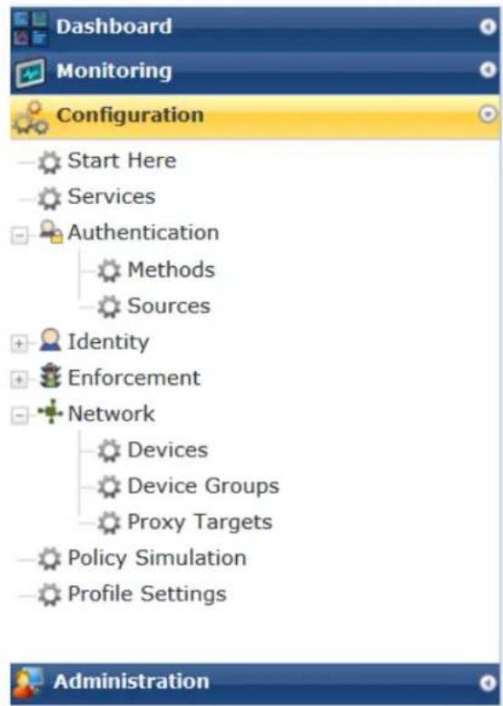
To access the W-ClearPass Configuration menu, select Configuration.
The W-ClearPass Configuration menu appears (see Figure 1):
Figure 1: W-ClearPass Policy Manager Configuration Menu
Start Here
The W-ClearPass Policy Manager Start Here page provides the ability to create templates for services that will allows you to define baseline policies and require specific data when you create services.
For more information, see Start Here: About Policy Manager Service Templates on page 36.
Services
The Services page provides options to add, modify, and remove a service. For more information, refer to the following sections:
• Services Architecture and Flow on page 35
- Start Here: About Policy Manager Service Templates on page 36
- Configuring Policy Manager Services on page 72
This page also shows the current list and order of services that W-ClearPass Policy Manager keeps track during authentication and authorization.
Authentication and Authorization
The Authentication page provides options to configure the following components:
- Adding and Configuring Authentication Methods on page 183
- Adding and Configuring Authentication Sources on page 207
- Configuring Authentication Methods for an Existing Service on page 181
Identity
The Identity page provides options on the settings required to configure W-ClearPass Policy Manager Identity settings. For more information, refer to the following sections:
- Configuring Single Sign-On on page 249
• Managing Local Users on page 252 - Adding and Modifying Endpoints on page 259
• Managing Static Host Lists on page 268
Posture
The Posture page provides options to configure posture policies and audit servers. For more information, refer to the following sections:
• Posture Architecture and Flow on page 279
- Creating a New Posture Policy on page 283
- Configuring Audit Servers on page 355
Enforcement
The Enforcement page provides options to configure the Enforcement Profiles globally and to reference in an enforcement policy that is associated with a service.
For more information, refer to the following section:
- Configuring Enforcement Policies on page 371
- Configuring Enforcement Profile on page 373
Network
The Network page provides options to configure the Network Access Device (NAD) that sends network access requests to Policy Manager using the supported RADIUS, TACACS+, or SNMP protocol. The NAD in this co is usually a mobility controller or a switch.
For more information, refer to the following sections :
- Adding a Network Device on page 464
- Adding and Modifying Device Groups on page 474
- Adding and Modifying Proxy Targets on page 473
- Configuring the Ingress Event Sources on page 732
Policy Simulation
The Policy Simulation page provides options to configure the Policy Simulation utility that applies a set of request parameters as input against a given policy component.
- For more information, refer to Configuring Policy Simulation on page 425.
Profile Settings
The Profile Settings page provides options to configure the following elements:
- Subnet Scans: See Configuring Subnet Scans on page 457 and Initiating a Network Discovery Scan on page 160.
• SNMP Configuration: See SNMP Credentials Configuration on page 154. - SSH Configuration: See SSH Credentials Configuration on page 156.
• WMI Configuration: See WMI Credentials Configuration.
Importing and Exporting Information
This section contains the following information:
- Importing Information Into W-ClearPass
- Exporting Information From W-ClearPass
The option to import information into or export information from a W-ClearPass server is available from top-level page in the W-ClearPass Policy Manager user interface.
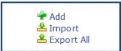
The Add, Import, and Export All options are displayed in the top-right corner of the configuration and administration pages:
Importing Information Into W-ClearPass
W-ClearPass Policy Manager allows you to import configuration and administration-related information. This information is stored as an XML file, which can be password protected.
For information about the tags and attributes in the XML file, refer to Appendix B, "Using the W-ClearPass Configuration API" in the W-ClearPass Deployment Guide.
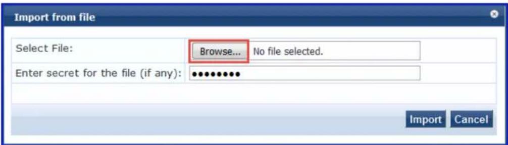
To import information into the current W-ClearPass server:
- Click the Import link.
The Import from file dialog box opens.
Figure 2: Import From File Page
-
Click Browse.
-
Browse to the file you want to import.
- Be sure to select an XML file that is in the correct format.
See Appendix B, "Using the W-ClearPass Configuration API" in the W-ClearPass Deployment Guide for more information about the format and contents of XML files.
- Enter secret for the file (if any): If you entered a secret key to encrypt the exported file, enter the same secret key to import the device back.
- Click Import.
Exporting Information From W-ClearPass
W-ClearPass Policy Manager allows you to export configuration and administration-related information from the current W-ClearPass server to an XML file. You can set this file to be password protected (see Table 2 for details).
To export multiple items, select the check boxes in the rows of the specific items that you want to expo To export information from the current W-ClearPass server:
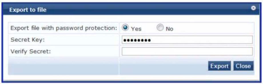
- Click the Export All link at the top-right corner of the configuration page. The Export to File dialog opens.
Figure 3: Export to File Dialog
- Specify the export parameters based on Table 2.
Specify the Export to file parameters as described in Table 2:
Table 2: Export to File Dialog Parameters
| Parameter Action/Description | |
| Export file with password protection | To export the file with password protection, choose Yes. |
| Secret Key/ Verify Secret You | can choose to encrypt the exported data with a key. This protects data such as shared secret from being visible in the exported file. To import it back, you specify the same key with which you exportedEnter the secret key. Then reenter the secret key. |
- Click Export.
An export dialog named for the selected W-ClearPass function opens:
Figure 4: Export XML File to Zip File Dialog
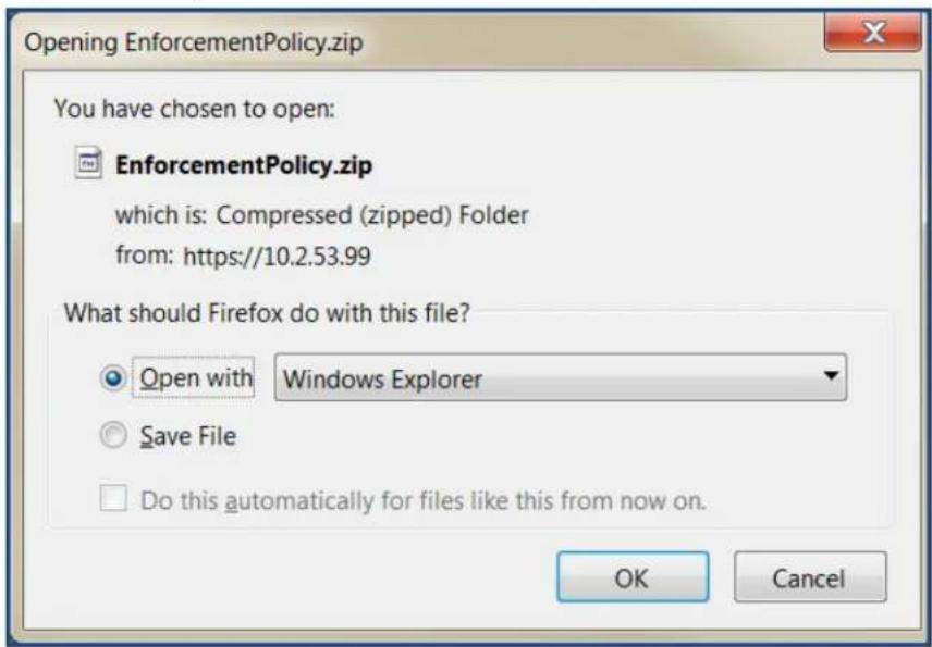
- Specify to open the zip file or save the XML file to your system.
- Click OK to proceed.
Export Considerations
The XML file generated from an export operation has a specific layout that is unique for each function in ClearPass user interface. If you import an XML file with an incorrect layout (usually because it's from the function), it will be rejected.
Aruba recommends that you note the message displayed when the XML operation is incorrect and what issue is—typically either because it's from the wrong export file or because it was modified incorrectly being imported.
This chapter describes the following topics:
• Services Architecture and Flow
- Start Here: About Policy Manager Service Templates
• Viewing the List of Services
- Configuring Policy Manager Services
The Policy Manager policy model groups policy components that serve a specific type of request into the Services page.
Services Architecture and Flow
Service Classification
Policy Manager services are classified as follows:
- Parents of their policy components, which are wrapped hierarchically and coordinated in processing requests.
- Siblings of other Policy Manager services within an order that determine the sequence in which they are tested against requests.
- Children of Policy Manager, which test requests against their rules to find a matching service for each request.
Service Flow Control
The flow control for requests follows this sequence:
- Policy Manager tests for the first request-to-service-rule match.
- The matching service coordinates execution of its policy components.
- Those policy components process the request to return enforcement profiles to the network access de and, optionally, return the posture results to the client.
Approaches to Creating a New Service
There are two approaches to creating a new service in W-ClearPass:
Bottom-Up
- Create all the policy components first as needed:
■ Authentication method
■ Authentication source
■ Role-mapping policy
■ Posture policy
■ Audit servers
■ Enforcement profiles
■ Enforcement policy
- Create the service using the Service creation wizard.
Top-Down
-
Start with the Service creation wizard.
-
Create the associated policy components as and when required, all in the same flow.
To help you get started, W-ClearPass provides 17 service types or templates. If these service types do suit your needs, you can create a new service using custom rules (as described in the next section Start Here:
About Policy Manager Service Templates).
Start Here: About Policy Manager Service Templates
This section includes the following information:
- Creating Templates for W-ClearPass Services
• Service Templates Provided
• Service Templates Supported for High Capacity Guest Mode
W-ClearPass Policy Manager Service templates provide a way to step through the template-creation process that you can easily create services and configure their specific components, such as role-mapping policies enforcement policies, associated network devices, and so on.
Creating Templates for W-ClearPass Services
To create templates for services for which you can define baseline policies and require specific data:
- Navigate to the Configuration > Start Here page.
The Start Here page opens.
Figure 5: Start Here Page (Partial View)
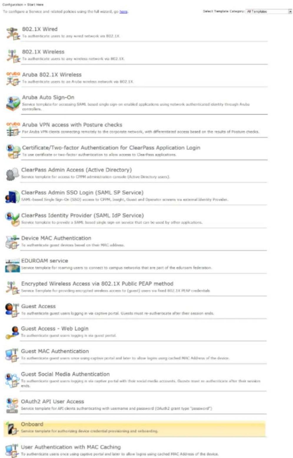
- Select the desired service template.
The configuration dialog for the selected service template opens, as shown in the following example fi
Figure 6: Auto Sign-On Service Template
Service Templates - Aruba Auto Sign-On

- Fill in the various fields that are presented in the templates—Policy Manager then creates the configur elements that are needed for that particular service.
Service Templates Provided
Refer to the following descriptions of the W-ClearPass service templates for configuration details:
• 802.1X Wired, 802.1X Wireless, and Dell 802.1X Wireless Service Template on page 46
• Auto Sign-On Service Template on page 50
- Dell VPN Access with Posture Checks Service Template on page 51
• Certificate/Two-Factor Authentication for W-ClearPass Application Login Service Template on page 53
• W-ClearPass Admin Access Service Template on page 55
• W-ClearPass Admin SSO Login (SAML SP Service) Service Template on page 56
• W-ClearPass Identity Provider (SAML IdP Service) Service Template on page 57
• Device MAC Authentication Service Template on page 58
• EDUROAM Service Template on page 60
- Encrypted Wireless Access via 802.1X Public PEAP Method Service Template on page 62
• Guest Access Service Template on page 63
• Guest Access Web Login Service Template on page 65
- Guest Authentication with MAC Caching Service Template on page 66
• Guest Social Media Authentication Service Template on page 68
- OAuth2 API User Access Service Template on page 70
- Onboard Service Template on page 70
Service Templates Supported for High Capacity Guest Mode
The following service templates are supported when the High Capacity Guest (HCG) mode is enabled:
• W-ClearPass Admin Access (Active Directory)
• W-ClearPass Admin SSO Login (SAML SP Service)
• W-ClearPass Identity Provider (SAML IdP Service)
• Encrypted Wireless Access via 802.1X Public PEAP method
- Guest Access
• Guest Access - Web Login
• Guest MAC Authentication
- OAuth2 API User Access
The following service types are supported when the HCG mode is enabled:
• MAC Authentication
• RADIUS Authorization
• RADIUS Enforcement
• RADIUS Proxy
• Dell Application Authentication
• Dell Application Authorization
• TACACS+ Enforcement
• Web-based Authentication
• Web-based Open Network Access
Viewing the List of Services
The Services page shows the current list and order of services that W-ClearPass Policy Manager follows during authentication and authorization. You can use the configured default service types or you can add additional services. Services included in square brackets "[]" indicate default services.
To view the list of services on the current W-ClearPass server:
Navigate to Configuration > Services.
The Services page opens:
Figure 7: Services Page
![Configuration * Services Services Filter: Name ▼ contains ▼ Go Clear Filter show 100 records ● Order ▲ Name Type Template Status 1. □ 1 Radius-generic-suri RADIUS RADIUS Enforcement ( Generic ) 2. □ 2 App-auth Application Aruba Application Authentication 3. □ 3 MAB-suri RADIUS MAC Authentication 4. □ 4 1X-Wireless RADIUS 802-1X Wireless 5. □ 5 Health-only WEBAUTH Web-based Health Check Only 6. □ 6 Tacacs-suri TACACS TACACS+ Enforcement 7. □ 7 [Policy Manager Admin Network Login Service] TACACS TACACS+ Enforcement 8. □ 8 Guest Operator Logins Application Aruba Application Authentication 9. □ 9 [AirGroup Authorization Service] RADIUS RADIUS Enforcement ( Generic ) 10. □ 10 [Aruba Device Access Service] TACACS TACACS+ Enforcement 11. □ 11 [Guest Operator Logins] Application Aruba Application Authentication 12. □ 12 sun-captive Guest Access RADIUS RADIUS Enforcement ( Generic ) 13. □ 13 Web-auth WEBAUTH Web-based Authentication Showing 1-13 of 13 Roorder Copy Export Delete](/content/2026/05/842116/images/b93ff9f765ace4d4f6dd21b46ff31ce7d888a4e0cd33c78980ec217ad2f3caaa.jpg)
The following table describes the Services parameters:
Table 3: Services Page Parameters
| Parameter | Description |
| Name Displays the name of the service. | |
| Type | Displays the type of authentication associated with the service. For example, RADIUS, Web Authentication, and TACACS. |
| Template | Specifies the type of the service template to create a service. |
| Status | Displays the status of the service. A green/red icon indicates enabled/disabled state. Click the icon to toggle the status of a service between Enabled and Disabled.NOTE: If a service is in Monitor mode, an [m] indicator is displayed next to the Status icon. |
For more information, see:
- Adding Services on page 1
• Modifying Services on page 1
• Reordering Services on page 44
Viewing Existing Services
You can view all configured services in a list or drill down to individual services in the Services page. You can filter the list of services by phrase or sort the services by order.
To view a list of services:
- Navigate to Configuration > Services.
The Services page opens:
Figure 8: Services Page
![Configuration > Services Services Filter: Name Order △ Name Type Template Status 1. 2. 3. 4. 5. [Policy Manager Admin Network Login Service] [TACACS] TACACS+ Enforcement 2. [AirGroup Authorization Service] RADIUS RADIUS Enforcement ( Generic ) 3. [Aruba Device Access Service] TACACS TACACS+ Enforcement 4. [Guest Operator Logins] Application Aruba Application Authentication 5. [Insight Operator Logins] Application Aruba Application Authentication Showing 1-5 of 5 Reorder Copy Export Delete Add Import Export All Show 10 records](/content/2026/05/842116/images/6f0f3a31643c421559baf7552a4431aa54578aecfe1387c9c01ba61d25977419.jpg)
- To view a service's details, select the service.
The Edit Services page opens to the Summary tab. The Summary tab provides the detailed information about the selected service configuration.
For example, to add authentication sources and authentication methods, click the Authentication tab.
The following figure displays the Summary page:
Figure 9: Details for an Individual Service
Services - 1X-Wireless
![Summary Service Authentication Service: Name: Description: Type: Status: Monitor Mode: More Options: 1X-Wireless 802.1X Wireless Access Service 802.1X Wireless Disabled Disabled - Service Rule Match ALL of the following conditions: Type Name Operator Value 1. Radius:JETF NAS-Port-Type EQUALS Wireless-802.11 (19) 2. Radius:JETF Service-Type BELONGS_TO Login-User (1), Framed-User (2), Authenticate-Only (8) Authentication: Authentication Methods: 1. [EAP PEAP] 2. [EAP FAST] 3. [EAP TLS] 4. [EAP TLS] 5. [EAP MSCHAPv2] 6. [MSCHAP] 7. [PAP] Authentication Sources: 1. 172.31.1.11 [Active Directory] 2. [Local User Repository] [Local SQL DB] Strip Username Rules: user:@ Roles: Role Mapping Policy: - Enforcement:](/content/2026/05/842116/images/9cc8aeb4078352deb2e845b582a8662847d68e2a93ed69529c1def38c00e0413.jpg)
Adding and Removing Services
This section provides the following information:
- Adding a New Service
- Modifying a Service
- Removing a Non-Default Service
You can modify a list of services by creating a new service, copying an existing service, and then modify deleting the existing service.
Adding a New Service
To add a new service:
- Navigate to Configuration > Services.
The Services page opens.
Figure 10: Services Page
![Configuration > Services Services Filter: Name Order △ Name Go Clear Filter Type Template Status 1. 2. 3. 4. 5. [Policy Manager Admin Network Login Service] [AirGroup Authorization Service] [Aruba Device Access Service] [Guest Operator Logins] [Insight Operator Logins] TACACS RADIUS TACACS+ Enforcement RADIUS Enforcement ( Generic ) TACACS Application Application Aruba Application Authentication Aruba Application Authentication Showing 1-5 of 5 Reorder Copy Export Delete Add Import Export All Show 10 records](/content/2026/05/842116/images/f5c9c828a0c4b8c632e8286b4640ae11b338fe4520ecec5bb41bcc90331b063e.jpg)
- Click Add.
The Add Services dialog opens.
Figure 11: Add Services Page
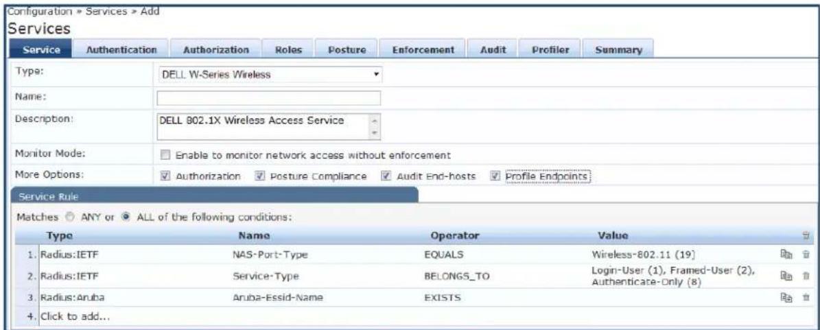
- Specify the Add Services configuration parameters as described in Table 4, then click Save.
Note that the available settings vary, depending upon the service type selected.
Table 4: Add Services Page Parameters
| Parameter Action/Description | |
| Type Select the | desired service type from the drop-down list.When working with service rules, you can select from the following namespace dictionaries:Application:The type of application for this service.Authentication:The Authentication method to be used for this service.Connection:Originator address (Src-IP-Address, Src-Port), Destination address (Dest-IP-Address, Dest-Port), and ProtocolDevice:Filter the service based on a specific device type, vendor, operating system location, or controller ID.Date:Time-of-Day, Day-of-Week, or Date-of-YearEndpoint:Filter based on endpoint information such as enabled/disabled, device, OS, location, and more.Host:Filter based on host Name, OSType, FQDN, UserAgent, CheckType, UniqueID, Agent-Type, and InstalledSHAs,RADIUS:W-ClearPass ships with a number of vendor-specific namespace dictionaries and distinguishes vendor-specific RADIUS namespaces with the notationRADIUS:vendor(sometimes with an additional suffix for a particular device). To add a dictionary for a vendor specific RADIUS namespace, navigate toAdministration > Dictionaries > Radius > Import(link).The notationRADIUS:IETFrefers to the RADIUS attributes defined in RFC 2865 and associated RFCs. As the name suggests, RADIUS namespace is only available if the request type is RADIUS.Any other supported namespace:SeeRules Editing and Namespaces on page 919for an exhaustive list of namespaces and their descriptions.To create new services, you can copy or import other services for useasisor as templates, or you can create a new service. |
| Name Enter the | name or label for the service you want to create. |
| Description | Enter a description that provides additional information to identify the service. This field is optional. |
| Monitor Mode | Optionally check theEnable to monitor network access without enforcementto allow authentication and health validation exchanges to take place between endpoint and Policy Manager, but without enforcement.InMonitor Mode, no enforcement profiles (and associated attributes) are sent to the network device.Policy Manager also allowsPolicy Simulation(Monitoring > Policy Simulation), where the administrator can test the results of a particular configuration of policy components. |
| More Options Select any of the available check boxes to enable the configuration tabs for those options.The available check boxes varies based on the type of service that is selected and may include one or more of the following:Authorization:Select an authorization source from the drop-down list to add the source or select theAdd new Authentication Sourcelink to create a new source.Posture Compliance:Select a Posture Policy from the drop-down list to add the policy or create a new policy by clicking the link. Select the default Posture token. Specify whether to enable auto-remediation of non-compliant end hosts. If this is enabled, then enter the Remediation URL. You can specify thePosture Serverfrom the drop-down list or add a new server by clicking theAdd new Posture Serverlink.Audit End-hosts:Select anAudit Server,either built-in or customized. Refer toConfiguring Audit Servers on page 355for audit server configuration steps. For this type of service, you can perform auditAlways, When posture is not available, orFor MAC authentication requests.You can specify to trigger an audit always, when posture is not available, or for MAC authentication requests. IfFor MAC authentication requestsis specified, then you can perform an auditFor known end-hosts onlyorFor unknown end hosts only, orFor all end hosts.Known end hosts are defined as those clients that are found in the authentication source(s) associated with this service. Performing audit on a client is an asynchronous task, which means the audit can be performed only after the MAC authentication request has been completed and the client has acquired an IP address through DHCP. Once the audit results are available, Policy Manager re-applies policies on the network deviceby one of the following ways:No Action:The audit does not apply policies on the network device after this audit.Do SNMP bounce:This option bounces the switch port or force an 802.1X re-authentication (both done using SNMP).NOTE:Bouncing the port triggers a new 802.1X or MAC authentication request by the client. If the audit server already has the posture token and attributes associated with this client in its cache, it returns the token and the attributes to Policy Manager.Trigger RADIUS CoA action:This option sends a RADIUS CoA command to the network device by Policy Manager.Optionally configureProfilersettings. Select one or more Endpoint Classification items from the drop down list, then select the RADIUS CoA action. You can also create a new action by selecting theAdd new RADIUS CoA Actionlink. | |
Creating a Service by Copying an Existing Service

You can perform a service copy operation only on a Publisher node.
To create a service template by making a copying an existing service:
From the Services page, select the check box by a service, then click Copy.
Modifying a Service
For full access in modifying a service, you must log in to the Publisher node.
To modify an existing service:
- From the Services page, click the check box for the service you want to modify.
The Configuration > Services > Edit >
dialog opens.
Figure 12: Edit Services Dialog
![Configuration > Services * Edit - [AirGroup Authorization Service] Services - [AirGroup Authorization Service] Summary Service Authentication Roles Enforcement Service: Name: [AirGroup Authorization Service] Description: Authorization service for AirGroup device access Type: RADIUS Enforcement ( Generic ) Status: Enabled Monitor Mode: Disabled More Options: - Service Rule Match ALL of the following conditions: Type Name Operator Value 1. Radius: IETF Called-Station-Id EQUALS AirGroup 2. Radius: IETF Service-Type EQUALS Authorize-Only (17) Authentication: Authentication Methods: [Allow All MAC AUTH] Authentication Sources: [Guest Device Repository] Strip Username Rules: - Roles: Role Mapping Policy: [AirGroup Version Match] Enforcement: Use Cached Results: Disabled Enforcement Policy: [AirGroup Enforcement Policy]](/content/2026/05/842116/images/8b7fddad438bd71617b39c6a7af15f0bea7a2576a713620d260bf85fe0b2804c.jpg)
- Select the Service tab to edit the service information.
- Modify the parameters as needed, then click Save.
You can also disable or enable a service from the Edit Services dialog page by clicking Disable or Enable in the lower right of the page.
Removing a Non-Default Service
To remove a non-default service:
- From the Services page, select the check box for the non-default service you want to remove.
- Click Delete.
Reordering Services
W-ClearPass Policy Manager evaluates requests against the service rules of each service that is configured the order in which these services are defined.
The service associated with the first matching service rule is then associated with this request.
To change the order in which service rules are processed, you can change the order of services.
To change the order of the services:
- Navigate to the Configuration > Services page.
The Services page appears.
Figure 13: Services Page Reorder Button
- Click the Reorder button (located on the lower-right portion of the page).
The Reorder Services page appears.
- Click the service you want to move to another position in the order (see Figure 14).
In this example, we will move Guest Operator Logins at the 5th position to the 2nd position.
Figure 14: Selecting the Service to Be Reordered
Configuration » Services » Reorder
Reorder Services
To reorder services, click on a service you want to move. Click on another service where you want to move the previously selected service.
![Order Name 1 [Policy Manager Admin Network Login Service] 2 [Insight Operator Logins] 3 [AirGroup Authorization Service] 4 [Aruba Device Access Service] 5 [Guest Operator Logins] Service Details: Name: [Policy Manager Admin Network Login Service] Template: TACACS+ Enforcement Type: TACACS Description: Service for access to Policy Manager Admin for network users Status: Enabled Service Rule ( (Connection:NAD-IP-Address EQUALS 127.0.0.1) ) AND (Connection:Protocol EQUALS TACACS)](/content/2026/05/842116/images/2d754a030eb88ceffdf705414572ec31108a90d95aea09028939cd12a98d688d.jpg)
- Select the position where you want to move the service (see Figure 15).
Figure 15: Selecting the Destination Order Position
![Configuration > Services > Reorder Reorder Services Order Name 1 [Policy Manager Admin Network Login Service] 2 [Guest Operator Logins] 3 Radius Service Move Up Move Down Service Details: Name: [Policy Manager Admin Network Login Service] Template: TACACS+ Enforcement Type: TACACS Description: Service for access to Policy Manager Admin for network users Status: Enabled Service Rule ( {Connection:NAD-IP-Address EQUALS 127.0.0.1} ) AND (Connection:Protocol EQUALS TACACS) Back to Services Save Cancel](/content/2026/05/842116/images/6d54555de5c801d454e1697ae447316fe26dd06e8c66fe39d4987478769aae6c.jpg)
- Click the selected destination position (see Figure 16).
The service is now moved to its new position in the services order.
Figure 16: Service Moved to New Order Position
Configuration » Services » Reorder
Reorder Services
To reorder services, click on a service you want to move. Click on another service where you want to move the previously selected service.
![Order Name 1 [Policy Manager Admin Network Login Service] 2 [Insight Operator Logins] 3 [AirGroup Authorization Service] 4 [Aruba Device Access Service] 5 [Guest Operator Logins] Service Details: Name: [Policy Manager Admin Network Login Service] Template: TACACS+ Enforcement Type: TACACS Description: Service for access to Policy Manager Admin for network users Status: Enabled Service Rule ( (Connection:NAD-IP-Address EQUALS 127.0.0.1) ) AND (Connection:Protocol EQUALS TACACS)](/content/2026/05/842116/images/401d93bfa389b751f0822c79aabb7d33bbce68906eef846f8e62a8786fd677ea.jpg)
6. Click Save.
You return to the Services page, which shows the service in its new order and displays the message: Services have been reordered successfully.
Configuring Service Templates
Refer to the following descriptions of the W-ClearPass Policy Manager Service Templates for configuration details:
- 802.1X Wired, 802.1X Wireless, and Dell 802.1X Wireless Service Template on page 46
• Auto Sign-On Service Template on page 50 - Dell VPN Access with Posture Checks Service Template on page 51
• Certificate/Two-Factor Authentication for W-ClearPass Application Login Service Template on page 53
• W-ClearPass Admin Access Service Template on page 55
• W-ClearPass Admin SSO Login (SAML SP Service) Service Template on page 56
• W-ClearPass Identity Provider (SAML IdP Service) Service Template on page 57
• Device MAC Authentication Service Template on page 58
• EDUROAM Service Template on page 60 - Encrypted Wireless Access via 802.1X Public PEAP Method Service Template on page 62
• Guest Access Service Template on page 63 - Guest Access Web Login Service Template on page 65
- Guest Authentication with MAC Caching Service Template on page 66
• Guest Social Media Authentication Service Template on page 68 - OAuth2 API User Access Service Template on page 70
- Onboard Service Template on page 70
802.1X Wired, 802.1X Wireless, and Dell 802.1X Wireless Service Template
- The 802.1X Wired service template is designed for wired end-hosts connecting through an Ethernet LAN using IEEE 802.1X authentication. The 802.1X Wired service template allows configuration of both identity-based and posture-based policies.
- The 802.1X Wireless template is for wireless end-hosts connecting through an 802.11 wireless access device or controller using IEEE 802.1X authentication. The 802.1X Wireless template allows configuring both identity-based and posture-based policies.
- The Dell W-Series 802.1X Wireless template is designed for wireless end-hosts connecting through a Dell W-Series 802.11 wireless access device or controller using IEEE 802.1X authentication (service rules customized for Dell WLAN controllers).
All three service templates are configured using identical parameters.

Figure 17: Service Templates > 802.1X Wired Service Template
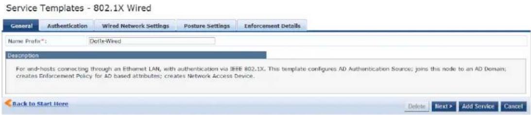
Adding a New Service for the Selected Service Template
To add a new service for the selected service template:
- Specify a unique Name Prefix (applies only to the selected template) in the General tab.
- Update the required fields in the Authentication and Enforcement Details sections.
- Click Add Service.
An entry for the new set of configuration is created under the Services, Roles, Role Mapping, Enforcement Policies and Profiles menus.
The sections shown in the figure and listed above are not same for all service templates. It is recommended to customize the respective templates when you add a new service.
Once you add a new service to the service template, the service denoted by the Name Prefix appears in the Select Prefix drop-down. Selecting a prefix from the drop-down populates the existing configuration for the service.
- Specify the parameters in the 802.1X Wired, 802.1X Wireless, and Dell W-Series 802.1X Wireless service templates as described in the following table:
Table 5: 802.1X Wired, 802.1X Wireless, and Dell W-Series 802.1X Wireless Service Template Parameters
| Parameter Action/Description | |
| General | |
| Select Prefix 1. | Select a prefix from the existing list of prefixes.This populates the preconfigured information in the Authentication and Enforcement Details sections. The Name Prefix field is not editable. |
| Name Prefix 2. | Enter a prefix that is appended to services using this template.Use this to identify the services that use templates. |
| Authentication | |
| Select Authentication Source | 1. Select any available authentication source from the list.The information updated in the Authentication and Enforcement Details tabs will be auto-populated. |
| Active Directory Name | 2. Enter the name of the Active Directory.This field is mandatory. |
| Description 3. | Enter a description that helps you to identify the characteristics of this template.This field is mandatory. |

Table 5: 802.1X Wired, 802.1X Wireless, and Dell W-Series 802.1X Wireless Service Template Parameters (Continued)
| Parameter Action/Description | |
| Server 4. Enter | the hostname or the IP address of the Active Directory server.This field is mandatory. |
| Port 5. Enter | the TCP port where the server is listening for a connection.This field is mandatory. |
| Identity 6. Enter | the Distinguished Name (DN) of the administrator account.This field is mandatory. |
| Password 7. Enter | the account password.This field is mandatory. |
| NetBIOS | 8. Enter the server Active Directory domain name.This field is mandatory. |
| Base DN | 9. Enter the DN of the node in your directory tree from which to start searching for records.This field is mandatory. |
| Enforcement Details | |
| Attribute Name | The attributes defined in the Authentication Source are listed here.1. Configure an optional enforcement policy based on the following attributes:■ Email■ Name■ Phone■ UserDN■ Company■ member of■ TitleFor example, you can configure an enforcement policy for a contractor specifying that " equals, then assign the [Contractor] Role." |
| Attribute Value | 2. Enter the active directory attribute value for the selected name in the Attribute Name field. |
| VLAN ID | 3. Enter the standard RADIUS-IETF VLAN ID. |
| Wired Network Settings | |
| Select Switch | 1. Select any switch from the drop-down list. |
| Device Name | 2. Enter the name of the device. |
| IP Address | 3. Enter the IP address of the device. |
| Vendor Name | 4. Select the manufacturer of the wired controller. |
| RADIUS Shared Secret | 5. Enter the shared secret that is configured on the controller and inside Policy Manager to and receive RADIUS requests. |
| Enable RADIUS CoA | 6. Select to enable RADIUS initiated Change of Authorization (CoA) on the network device. |
| RADIUS CoA Port | Specifies the default port 3799 if RADIUS CoA is enabled.7. Change this value only if you defined a custom port on the network device. |
| Wireless Network Settings | |
| Wireless Controller Name | 1. Enter the name of the wireless controller. |
| Controller IP Address | 2. Enter the IP address of the wireless controller. |
| Vendor Name | 3. Select the manufacturer of the wireless controller. |
| RADIUS Shared Secret | 4. Enter the shared secret that is configured on the controller and Policy Manager to send and receive RADIUS requests. |
| Enable RADIUS CoA | 5. Select to enable RADIUS initiated CoA on the network device. |
| RADIUS CoA Port | Specifies the default port 3799 if RADIUS CoA is enabled.6. Change this value only if you defined a custom port on the network device. |
| Posture Settings | |
| Enable Posture Checks | 7. Select the check box to perform health checks post authentication. This enables the Host Operating System and Quarantine Message fields. |
| Host Operating System | 8. Select the operating system: Windows, Linux, or Mac OS X. |
| Quarantine Message | 9. Specify the quarantine message that will appear on the client. |
Deleting a Service
To delete a service:
-
Select the appropriate service from the Select Prefix drop-down.
-
Click Delete.
All the configured entries under the Services, Authentication Source, Roles, Role Mapping, Enforcement Policies and Profiles menu are deleted if these entities were created from the service template.
When you edit or delete the entities of a service, a message is displayed at the top of the entity page stating that selected entity was created through the service template.
Do not delete entities used in service configurations that are not created using the service template.
Auto Sign-On Service Template
The Auto Sign-On service template allows you to access the SAML-based single sign on enabled applications (such as Policy Manager, Guest, Onboard, and W-ClearPass Insight) using a network authenticated (802.1X identity through controllers.
The following figure displays the Auto Sign-On service template :
Figure 18: Auto Sign-On Service Template
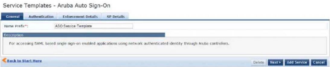
Specify the Auto Sign-On service template parameters as described in the following table:
Table 6: W-ClearPass Auto Sign-On Service Template Parameters
| Parameter Action/Description | |
| General | |
| Select Prefix Select | a prefix from the existing list of prefixes.This field populates the pre-configured information in the Authentication, SP details, and Enforcement Details sections. The Name Prefix field is not editable. |
| Name Prefix Enter | a prefix that you want to append to services using this template.Use this to identify services that use templates. |
| Authentication | |
| Select Authentication Source | Select an authentication source from the list.The information provided in the Authentication, Enforcement Details, and SP details tabs are auto-populated. |
| Active Directory Name | Enter the hostname or the IP address of the Active Directory server.This field is mandatory. |
| Description | Enter a description that helps you to identify the characteristics of this template.This field is mandatory. |
| Server | Enter the hostname or the IP address of the Active Directory server. This field is mandatory. |
| Identity | Enter the DN of the administrator account. This field is mandatory. |
| NETBIOS | Enter the server Active Directory domain name. This field is mandatory. |
| Base DN Enter the DN of the administrator account. This field is mandatory. | |
| Password Enter the account password. This field is mandatory. | |
| Port Enter the TCP port where the server is listening for a connection.This value defaults to 389. This field is mandatory. | |
| Enforcement Details | |
| Create new Enforcement Policy | Configure an optional enforcement policy based on the following attributes:DepartmentEmailNamePhoneUserDNcompany memberOfTitle |
| SP Details | |
| SP URL | Enter the Service Provider (SP) URL. |
| Attribute Name | Enter attribute names and assign values to those names.These name/value pairs are included in SAML responses. |
| Attribute Value | |
Dell VPN Access with Posture Checks Service Template
This template authenticates Dell VPN clients connecting remotely to corporate networks. Differentiated acc is based on the result of posture checks. This template:
- Configures an Active Directory authentication source
- Joins this node to the Active Directory domain
- Creates an enforcement policy for Active Directory-based attributes
- Creates a Network Access Device (NAD)

Posture checks are not performed if High Capacity Guest mode is enabled in the cluster.
You can view only the default user role in the Dell User Roles for different access privileges tab if HCG mode is enabled in the cluster.
The following figure displays the Dell VPN Access with Posture Checks service template:
Figure 19: Dell VPN Access with Posture Checks Service Template
Configuration » Start Here
Service Templates - Aruba VPN access with Posture checks

Specify the Dell VPN Access with Posture Checks service template parameters as described in the following table:
Table 7: Dell VPN Access with Posture Checks Service Template Parameters
| Parameter Action/Description | |
| General | |
| Select Prefix Select a prefix | from the existing list of prefixes.This populates the preconfigured information in the Authentication Dell Wireless Controller for VPN Settings and Dell User Roles for different access privileges sections. The Name Prefix field is not editable. |
| Name Prefix Enter a prefix | that you want to append to services using this template. Use this to identify services that use templates. |
| Authentication | |
| Select Authentication Source | Select an authentication source from the list.The information provided in the Authentication, Dell Wireless Controller for VPN Settings, and Dell User Roles for different access privileges sections are auto-populated. |
| Active Directory Name | Enter the Active Directory name. |
| Description | Enter a description that helps you to identify the characteristics of this template. |
| Server | Enter the host name or the IP address of the Active Directory server. |
| Identity | Enter the Distinguished Name (DN) of the administrator account. |
| NetBIOS | Enter the server Active Directory domain name. |
| Base DN | Enter the Distinguished Name (DN) of the node in your directory tree from which to start searching for records. |
| Password | Enter the account password. |
| Port | Enter the TCP port where the server is listening for a connection. |
| Dell Wireless Controller for VPN Access | |
| Select Wireless Controller Select a wireless controller from the drop-down list. | |
| Wireless controller name Enter the name given to the wireless controller. | |
| Controller IP Address Enter the wireless controller's IP address. | |
| Vendor Name Select the manufacturer of the wireless controller. | |
| RADIUS Shared Secret Enter the shared secret that is configured on the controller and inside Policy Manager to send and receive RADIUS requests. | |
| Enable RADIUS CoA Select this option to enable RADIUS initiated CoA on the network device. | |
| RADIUS CoA Port Specifies the default port 3799 if RADIUS CoA is enabled.NOTE: Change this value only if you defined a custom port on the network device. | |
| Dell User Roles for different access privileges - Create a new Enforcement Policy | |
| Initial Role (before posture checks) | Enter the initial role of the client before posture checks are performed. |
| Quarantined Role (failed posture checks) | Enter the role of clients that fail posture checks. |
| Healthy Role (passed posture checks) | Enter the role of the client after a posture check is passed and deemed healthy. |
Certificate/Two-Factor Authentication for W-ClearPass Application Login Service Template
This service template allows administrators and operators to log in to W-ClearPass using a smart card ar (Transport Layer Security) certificates.
To log in using a smart card and TLS certificates, ensure that the services are configured using the Certificate/Two-Factor Authentication for ClearPass Application Login service template.
The following figure displays the Certificate/Two-Factor Authentication for ClearPass Application Login service template:
Figure 20: Certificate/Two-Factor Authentication Service Template
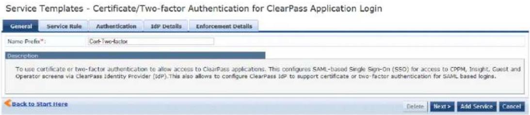
Specify the Certificate/Two-Factor Authentication for ClearPass Application Login service template parameters as described in the following table:
Table 8: W-ClearPass Certificate/Two-Factor Authentication Service Template Parameters
| Parameter Action/Description | |
| General | |
| Select Prefix 1. Select a | prefix from the existing list of prefixes.This field populates the pre-configured information in the Authentication, SP details, and Enforcement Details sections. The Name Prefix field is not editable. |
| Name Prefix 2. Enter a | prefix that you want to append to services using this template.Use this to identify services that use templates. |
| Service Rule | |
| Application | 3. Select the application for which SAML-based Single Sign-On (SSO) should be enabled from the following options: Policy Manager, Guest, Insight, and Onboard. |
| Authentication | |
| Select Authentication Source | 4. Select an authentication source from the list.The information provided in the Authentication, Enforcement Details, and SP details tabs are auto-populated. |
| Active Directory Name | 5. Enter the hostname or the IP address of the Active Directory server.This field is mandatory. |
| Description | 6. Enter a description that helps you to identify the characteristics of this template.This field is mandatory. |
| Server | 7. Enter the hostname or the IP address of the Active Directory server.This field is mandatory. |
| Port | 8. Enter the TCP port where the server is listening for a connection.The default value is value defaults to 389. This field is mandatory. |
| Identity | 9. Enter the DN of the administrator account. This field is mandatory. |
| Password | 10. Enter the account password. This field is mandatory. |
| NETBIOS | 11. Enter the server Active Directory domain name. This field is mandatory. |
| Base DN | 12. Enter the Distinguished Name (DN) of the administrator account. This field is mandatory. |
| IdP Details | |
| Page Name | 13. Select the Web Login pages from the drop-down list.For more information, see the next section, Creating a New Web Login Page. |
| Enforcement Details | |
| Certificate Attribute - Super Admin Condition | 14. Select the certificate attribute from the drop-down list.15. Enter the value in theSuper Admin Conditionfield that matches theCertificate Attributevalue to provide the super administrator access. |
| Certificate Attribute - Read Only Admin Condition | 16. Select the certificate attribute from the drop-down list.17. Enter the value in theRead Only Admin Conditionfield that matches theCertificate Attributevalue to provide the Read-Only administrator access. |
| Certificate Attribute - Help Desk Admin Condition | 18. Select the certificate attribute from the drop-down list.19. Enter the value in theHelp Desk Admin Conditionfield that matches theCertificate Attributevalue to provide the help desk administrator access. |
Creating a New Web Login Page
To create a new Web Login page:
- Click the Add New Guest Web Login page link.
This opens the W-ClearPass Guest application in which you can create a new Guest Web Login page.
-
To log in using a smart card and TLS certificates, navigate to ClearPass Guest > Configuration > Pages > Web Logins.
-
In the Vendor Settings field, select Single Sign On -SAML Identity Provider.
a. When you select Optional - Request a client certificate from the user, but allow none from the Client Certificate field, the user needs to provide a certificate, username, and password.
b. When you select Required - Require a client certificate from the user from the Client Certificate field, the user needs to provide only certificates for authentication.
This enables the Authentication field with the following options:
- Certificate only - No username or password required: Requires only certificate authentication.
Credentials - Also require a username and password: Requires the username and password.
W-ClearPass Admin Access Service Template
This template is designed for services that authenticate users against Active Directory.
Use Active Directory attributes to determine appropriate privilege levels for W-ClearPass Policy Manager a access.
The following figure displays the W-ClearPass Admin Access service template:
Figure 21: W-ClearPass Admin Access Service Template
Service Templates - ClearPass Admin Access (Active Directory)

Specify the W-ClearPass Admin Access service template parameters as described in the following table:
Table 9: W-ClearPass Admin Access Service Template Parameters
| Parameter Action/Description | |
| General | |
| Select Prefix Select a | prefix from the existing list of prefixes.This populates the preconfigured information in the Authentication and Role Mapping sections. The Name Prefix field is not editable. |
| Name Prefix Enter a | prefix that you want to append to services using this template. Use this to identify services that use templates. |
| Authentication: Create an Active Directory Authentication Source | |
| Select Authentication Source | Select an authentication source from the list.The information updated in the Authentication and Role Mapping tabs are auto-populated. |
| Active Directory Name | Enter the hostname or the IP address of the Active Directory server. This field is mandatory. |
| Description Enter a description that helps to identify the characteristics of this template. This field is mandatory. | |
| Server | Enter the hostname or the IP address of the Active Directory server. This field is mandatory. |
| Port | Enter the TCP port where the server is listening for a connection. This field is mandatory. |
| Identity | Enter the Distinguished Name (DN) of the administrator account. This field is mandatory. |
| Password | Enter the account password. This field is mandatory. |
| NetBIOS | Enter the server Active Directory domain name. This field is mandatory. |
| Base DN | Enter the DN of the administrator account. This field is mandatory. |
| Role Mapping | |
| Attribute Name | Select the Active Directory attribute. |
| Super Admin Condition | Defines the various privilege levels. |
| Read Only Admin Condition | |
| Help Desk Condition | |
W-ClearPass Admin SSO Login (SAML SP Service) Service Template
This application service template allows Security Asserting Markup Language (SAML)-based Single Sign-On authenticated users to access Policy Manager, Guest, Insight, and Operator pages.
The following figure displays the W-ClearPass Admin SSO Login service template:
Figure 22: W-ClearPass Admin SSO Login (SAML SP Service) Service Template
Service Templates - ClearPass Admin SSO Login (SAML SP Service)

Specify the W-ClearPass Admin SSO Login service template parameters as described in the following table:
Table 10: W-ClearPass Admin SSO Login Service Template Parameters
| Parameter | Action/Description |
| General | |
| Select Prefix | Select a prefix from the existing list of prefixes.This populates the preconfigured information in theService Ruletab. TheName Prefixfield is not editable. |
| Name Prefix | Enter a prefix that you want to append to services using this template.Use this to identify services that use templates. |
| Service Rule | |
| Application Select the application that single-sign-on-authenticated administrative users can access. | |
W-ClearPass Identity Provider (SAML IdP Service) Service Template
This template is designed for services that act as an Identity Provider (IdP). This Identity Provider features the Layer-2 device, RADIUS server, and SAML Identity Provider to work together and deliver application-based single sign-on using network authentication information.
The following figure displays the W-ClearPass Identity Provider (SAML IdP Service) service template:
Figure 23: W-ClearPass Identity Provider (SAML IdP Service)
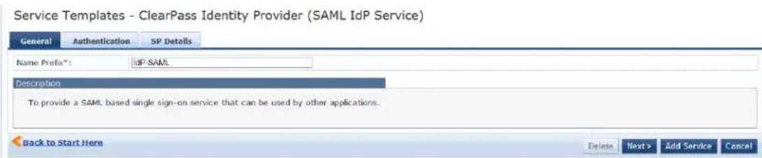
Specify the W-ClearPass Identity Provider (SAML IdP Service) service template parameters:
Table 11: W-ClearPass Identity Provider (SAML IdP Service) Service Template Parameters
| Parameter Action/Description | |
| General | |
| Select Prefix Select | a prefix from the existing list of prefixes.This populates the pre-configured information in the Authentication and SP Details sections. The Name Prefix field is not editable. |
| Name Prefix Enter | a prefix that you want to append to services using this template. Use this to identify services that use templates. |
| Authentication | |
| Select Authentication Source | Select an authentication source from the list, the information updated in the Authentic and SP Details tabs are auto-populated. |
| Active Directory Name | Enter the hostname or the IP address of the Active Directory server. This field is man |
| Description Enter a | description that helps you to identify the characteristics of this template. This field is mandatory. |
| Server | Enter the hostname or the IP address of the Active Directory server. This field is mandatory. |
| Identity | Enter the Distinguished Name (DN) of the administrator account. This field is mandatory. |
| NetBIOS | Enter the Active Directory server domain name. This field is mandatory. |
| Base DN | Enter the Distinguished Name (DN) of the administrator account. This field is mandatory. |
| Password | Enter the account password. This field is mandatory. |
| Port | Enter the TCP port where the server is listening for a connection. This field is mandatory. |
| SP Details | |
| SP URL | Enter the Service Provider (SP) URL. |
| Attribute Name | Enter the name of the attributes and assign values to those names. These name/value pairs are included in SAML responses. |
| Attribute Value | |
Device MAC Authentication Service Template
This template is designed for authenticating guest devices based on their MAC address.
You can limit the network access for guest devices that do not have user directly associated with them specific duration in days or by the bandwidth limit.
The following figure displays the Device MAC Authentication service template:
Figure 24: Device MAC Authentication Service Template
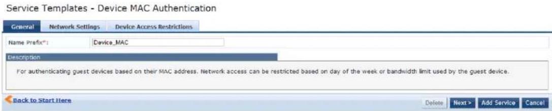
Specify the parameters in the Device MAC Authentication service template as described in the following table:
Table 12: Device MAC Authentication Template Parameters
| Parameter Action/Description | |
| General | |
| Select Prefix Select a prefix from the existing list of prefixes.This populates the preconfigured information in the Authentication and SP Details sections.The Name Prefix field is not editable. | |
| Name Prefix Enter a prefix that you want to append to services using this template. Use this to identify services that use templates. | |
| Network Settings | |
| Select Device Select a preconfigured device from the drop-down list.To create a new device, leave this field blank and enter the remaining fields. | |
| Device Name The name of the device is populated automatically based on the device selected from the Select Device field. If you create a new device, enter the name of the device. | |
| IP Address The IP address of the device is populated automatically based on the device selected from the Select Device field. If you create a new device, enter the name of the device. | |
| Vendor Name The name of the manufacturer of the device is populated automatically based on the device selected from the Select Device field. If you create a new device, enter the name of the manufacturer of the device. | |
| RADIUS Shared Secret | Enter the shared secret that is configured on the controller and in Policy Manager to send receive RADIUS requests. |
| Enable RADIUS CoA | Select to enable RADIUS initiated Change of Authorization (CoA) on the network device. |
| RADIUS CoA Port | Specifies the default port 3799 if RADIUS CoA is enabled. Change this value only if you defined a custom port on the network device. |
| Device Access Restrictions | |
| Days allowed for access | Select the days on which network access is allowed. |
| Maximum bandwidth allowed per device | Enter a number to set an upper limit for the amount of data in megabytes to which a allowed per day.A value of 0 (zero), the default, means no limit is set. |
EDUROAM Service Template
This template is designed for the following scenarios:
- Local campus users connecting to eduroam from the local wireless network.
• Roaming users from an eduroam campus connecting to their campus network.
• Roaming users connecting from local campus or other campuses that are part of the eduroam federation.
You cannot view the EDUROAM service template if the HCG mode is enabled in the cluster.
The following figure displays the EDUROAM service template:
Figure 25: EDUROAM Service Template
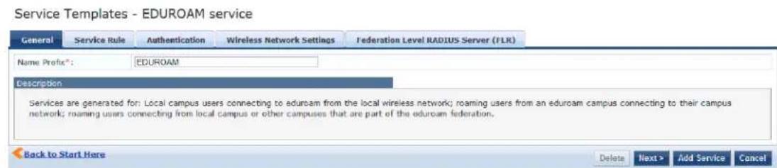
Specify the parameters used in the EDUROAM service template as described in the following table:
Table 13: EDUROAM Service Template Parameters
| Parameter Action/Description | |
| General | |
| Select Prefix | Select a prefix from the existing list of prefixes.This populates the pre-configured information in the Authentication, Service R Wireless, and Federation Level Radius Server (FLR) tabs. The Name Prefix field is not editable. |
| Name Prefix | Enter a prefix that you want to append to services using this template.Use this to identify services that use templates. |
| Service Rule | |

Table 13: EDUROAM Service Template Parameters (Continued)
| Parameter Action/Description | |
| Enter domain details Enter | the domain name of the network. For example, @edunet.ucla.com. This field is mandatory. |
| Select Vendor Select the vendor | vendor of the network device. This field is mandatory. |
| Authentication | |
| Select Active Directory Select | an authentication source from the list, the information updated in the Authentication, Wireless, and Federation Level Radius Server (FLR) tabs are auto-populated. |
| Active Directory Name Enter | the hostname or the IP address of the Active Directory server. This field is mandatory. |
| Description Enter a description that helps you identify the characteristics of this template. This field is mandatory. | |
| Server Enter the host name or the IP address of the Active Directory server. This field is mandatory. | |
| Identity Enter the Distinguished Name (DN) of the administrator account. This field is mandatory. | |
| NetBIOS Enter the server Active Directory domain name. This field is mandatory. | |
| Base DN Enter the Distinguished Name (DN) of the administrator account. This field is mandatory. | |
| Password | Enter the account password. This field is mandatory. |
| Port | Enter the TCP port where the server is listening for a connection. This field is mandatory. |
| Wireless Network Settings | |
| Select wireless controller | Select a wireless controller from the drop-down list. |
| Wireless controller name | Enter the name given to the wireless controller. |
| Controller IP Address | Enter the IP address of the wireless controller. |
| Vendor Name | Select the manufacturer of the wireless controller. |
| RADIUS Shared Secret | Enter the shared secret that is configured on the controller and inside Policy Manager to send and receive RADIUS requests. |
| Enable RADIUS CoA | Select to enable RADIUS initiated CoA on the network device. |
| RADIUS CoA Port | Specifies the default port 3799 if RADIUS CoA is enabled. Change this value only if you defined a custom port on the network device. |
| Federation Level RADIUS Server (FLR) | |
| Host Name Enter the host | name of the federation RADIUS server. |
| IP Address Enter the IP address of the federation RADIUS server. | |
| Vendor Name Select the manufacturer of the wireless controller. | |
| RADIUS Shared Secret | Enter the shared secret that is configured on the controller and inside Policy Manager to send and receive RADIUS requests. |
| Enable RADIUS CoA | Select to enable RADIUS initiated CoA on the network device. |
| RADIUS CoA Port | Specifies the default port 3799 if RADIUS CoA is enabled.NOTE: Change this value only if you defined a custom port on the network de |
| RADIUS Authentication Port | Enter the port number for the RADIUS Authentication Port. |
| RADIUS Accounting Port | Enter the port number for the RADIUS Accounting Port. |
Encrypted Wireless Access via 802.1X Public PEAP Method Service Template
This template is designed for providing encrypted wireless access to users using fixed 802.1X PEAP crede
This template configures an EAP PEAP Public type authentication method and creates an enforcement policy for network access.
The following figure displays the Encrypted Wireless Access via 802.1X Public PEAP Method service template:
Figure 26: Encrypted Wireless Access via 802.1X Public PEAP Method Service Template
Service Templates - Encrypted Wireless Access via 802.1X Public PEAP method

Specify the parameters used in the Encrypted Wireless Access via 802.1X Public PEAP method service template s described in the following table:
Table 14: Encrypted Wireless Access via 802.1X Public PEAP Method Service Template Parameters
| Parameter Action/Description | |
| General | |
| Name Prefix Enter | a prefix that you want to append to services using this template. You can use this to identify services that use templates. |
| Wireless Network Settings | |
| Select wireless controller | Select a wireless controller from the drop-down list. |
| Wireless controller name | Enter the name given to the wireless controller. |
| Controller IP Address | Enter the IP address of the wireless controller. |
| Vendor Name Select | the manufacturer of the wireless controller. |
| RADIUS Shared Secret | Enter the shared secret that is configured on the controller and inside Policy Manager and receive RADIUS requests. |
| Enable RADIUS CoA | Select to enable RADIUS initiated CoA on the network device. |
| RADIUS CoA Port | Specifies the default port 3799 if RADIUS CoA is enabled.NOTE: Change this value only if you defined a custom port on the network device. |
| Authentication Method | |
| Public Username Enter the public username for the EAP PEAP Public type authentication method. | |
| Public Password Enter the password for the EAP PEAP Public type authentication method. | |
| Access Restrictions | |
| Days allowed for access | Select the days on which network access is allowed. |
Guest Access Service Template
This template is designed for authenticating guest users who log in using captive portal.
Guests must reauthenticate after session expiry. Guest access can be restricted based on day of the week bandwidth limit, and number of unique devices used by the guest user.
The following figure displays the Guest Access service template:
Figure 27: Guest Access Service Template
Service Templates - Guest Access

Specify the parameters used in the Guest Access service template as described in the following table:
Table 15: Guest Access Service Template Parameters
| Parameter Action/Description | |
| General | |
| Select Prefix Select | any one prefix from the existing list of prefixes.This populates the pre-configured information in the Wireless Network Settings and Guest Access Restrictions sections. The Name Prefix field is not editable. |
| Name Prefix Enter a | prefix that you want to append to services using this template. Use this to identify services that use templates. |
| Wireless Network Settings | |
| Wireless SSID for Guest access | Enter the SSID value here. |
| Select wireless controller | Select the wireless controller from the drop-down list if you already configured. |
| Wireless controller name | Enter the name of the wireless controller. |
| Controller IP Address | Enter the wireless controller's IP address. |
| Vendor Name Select | the manufacturer of the wireless controller. |
| RADIUS Shared Secret | Enter the shared secret that is configured on the controller and inside Policy Manage send and receive RADIUS requests. |
| Enable RADIUS CoA | Select to enable RADIUS initiated CoA on the network device. |
| RADIUS CoA Port | Specifies the default port 3799 if RADIUS CoA is enabled.NOTE: Change this value only if you defined a custom port on the network device. |
| Posture Settings | |
| Enable Posture Checks | Select the check box to perform health checks post authentication.This enables the Host Operating System and Quarantine Message fields. |
| Host Operating System | Select the operating system: Windows, Linux, or MacOS X. |
| Quarantine Message | Specify the quarantine message that will appear on the client. |
| Initial Role/ VLAN Enter the initial role of the client before posture checks are performed. | |
| Quarantine Role/VLAN | Enter the role of clients that fail posture checks. |
| Guest Access Restrictions | |
| Days allowed for access | Select the days of the week that guest users are allowed network access. |
| Maximum bandwidth allowed per user | Enter a number to set an upper limit for the amount of data in Megabytes (MB) to user is allowed per day.A value of 0 (zero), the default, means no limit is set. |
Guest Access Web Login Service Template
This service authenticates guests logging in using the Guest portal.
To use this service, create a Guest Web Login page that sets the Pre-Auth Check option to AppAuth - Check using Dell Application Authentication.
The following figure displays the Guest Access Web Login service template:
Figure 28: Guest Access Web Login Service Template
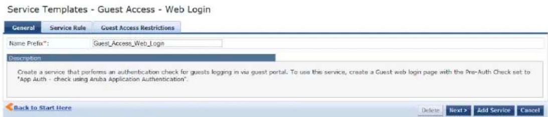
Specify the Guest Access Web Login service template parameters as described in the following table:
Table 16: Guest Web Login Service Template Parameters
| Parameter Action/Description | |
| General | |
| Select Prefix Select any one prefix from the existing list of prefixes.This populates the preconfigured information in the Service Rule and Guest Web Login sections. The Name Prefix field is not editable. | |
| Name Prefix Enter a prefix that you want to append to services using this template. | |
| Use this to identify services that use templates. | |
| Service Rule | |
| Page name | Enter the name of the Guest Web Login page. |
| Add New Guest Web Login page | Click this link to launch a new Web session for the Guest Web Login page. |
| Guest Access Restrictions | |
| Days allowed for access | Select the days of the week that guest users are allowed network access.NOTE: All seven days of the week are enabled by default. |
Guest Authentication with MAC Caching Service Template
This template is designed for authenticating guest accounts based on the cached MAC addresses used di authentication.
A guest can belong to a specific role such as Contractor, Guest, or Employee, and each role can have a lifetime for the cached MAC address.
The following figure displays the Guest MAC Authentication service template:
Figure 29: Guest MAC Authentication Service Template
Service Templates - Guest MAC Authentication
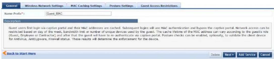
Specify the Guest MAC Authentication service template parameters as described in the following table:
Table 17: Guest MAC Authentication Service Template Parameters
| Parameter Action/Description | |
| General | |
| Select Prefix Select a | prefix from the existing list of prefixes.This populates the preconfigured information in the Wireless Network Settings, MAC Caching Settings, and Guest Access restrictions tabs. The Name Prefix field is not editable. |
| Name Prefix Enter a | prefix that you want to append to services using this template. Use this to identify services that use templates. |
| Wireless Network Settings | |
| Wireless SSID Enter the SSID name of your network. | |
| Wireless Controller Name | Enter the name of the wireless controller. |
| Controller IP Address | Enter the wireless controller's IP address. |
| Vendor Name Select | the manufacturer of the wireless controller. |
| RADIUS Shared Secret | Enter the shared secret that is configured on the controller and inside Policy Manager to send and receive RADIUS requests. |
| Enable RADIUS CoA | Select this check box to enable RADIUS initiated CoA (Change of Authorization) on the network device. |
| RADIUS CoA Port Specifies the default port 3799 if RADIUS CoA is enabled.NOTE: Change this value only if you defined a custom port on the network device. | |
| MAC Caching Settings | |
| Cache Duration for Employee | From the Account Expiry Time drop-down, select the MAC caching duration for employees:One DayOne WeekOne MonthSix MonthsNOTE: When this duration expires, users must reauthenticate via the captive portal.NOTE: You must specify the cache duration for at least one role. |
| Cache Duration for Guest | From the Account Expiry Time drop-down, select the MAC caching duration for guests:One DayOne WeekOne MonthSix Months |
| Cache Duration for Contractor | From the Account Expiry Time drop-down, select the MAC caching duration for contractors:One DayOne WeekOne MonthSix Months |
| Posture Settings | |
| Enable Posture Checks | Select the check box to perform health checks post authentication. This enables theOperating System and Quarantine Messagefields. |
| Host Operating System | Select the operating system(s): Windows, Linux, or Mac OS X. |
| Quarantine Message | Specify the quarantine message that will appear on the client. |
| Initial Role/VLAN Enter | the initial role of the client before posture checks are performed. |
| Quarantine Role/VLAN | Enter the role of clients that fail posture checks. |
| Access Restrictions | |
| Enforcement Type Select one of the following enforcement types:• Dell Role Enforcement• VLAN Enforcement• Filter ID-Based EnforcementNOTE: Enforcement Type applies to the Captive Portal Access, Employee Access, Guest Access, and Contractor Access fields. At least one of these must be specified. | |
| Captive Portal Access | TBD |
| Days allowed for access | Select the days of the week that guest users are allowed network access.By default, all seven days of the week are enabled. |
| Maximum number of devices allowed per user | Enter the maximum number of devices that users can connect to the network. |
| Maximum bandwidth allowed per user | Enter a number to set an upper limit for the amount of data in megabytes to which is allowed per day. A value of 0 (zero), the default, means no limit is set. |
| Employee Access | TBD |
| Guest Access | TBD |
| Contractor Access TBD | |
Guest Social Media Authentication Service Template
This template is designed for authenticating guest users logging in through the captive portal with their media accounts, such as Google, Facebook, LinkedIn, and Twitter. Guests must reauthenticate after the session ends.
The following figure displays the Guest Social Media Authentication service template:
Figure 30: Guest Social Media Authentication Service Template
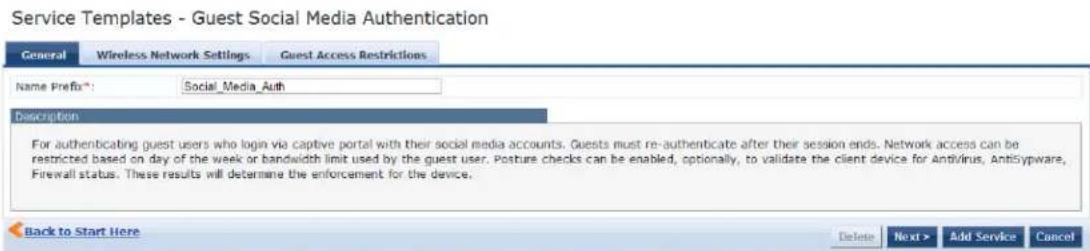
Specify the Guest Social Media Authentication service template parameters as described in the following table:
Table 18: Guest Social Media Service Template Parameters
| Parameter Description | |
| General | |
| Select Prefix Select | a prefix from the existing list of prefixes.This populates the preconfigured information in the Wireless Network Settings, MAC Caching Settings, and Guest Access restrictions tabs. The Name Prefix field is not editable. |
| Name Prefix Enter | a prefix that you want to append to services using this template. Use this to identify services that use templates. |
| Wireless Network Settings | |
| Wireless Controller Name | Enter the name of the wireless controller. |
| Controller IP Address | Enter the wireless controller's IP address. |
| Vendor Name Select | the manufacturer of the wireless controller. |
| RADIUS Shared Secret | Enter the shared secret that is configured on the controller and inside Policy Manager and receive RADIUS requests. |
| Enable RADIUS CoA | Select to enable RADIUS initiated CoA (Change of Authorization) on the network device. |
| RADIUS CoA Port | Specifies the default port 3799 if RADIUS CoA is enabled.NOTE: Change this value only if you defined a custom port on the network device. |
| Guest Access Restrictions | |
| Social Login Provider | Select the social media network options: Google, Facebook, LinkedIn, and Twitter. |
| Days allowed for access | Select the days of the week that the guest users are allowed network access.By default, all seven days of the week are enabled. |
| Maximum bandwidth allowed per user | Specify the maximum amount of data in Megabytes a user is allowed per day. A value (zero) means no limit is set (the default). |
OAuth2 API User Access Service Template
This template is designed for configurations that supports W-ClearPass Policy Manager authenticating API clients with the username and OAuth2 grant-type password.
- The OAuth2 API User Access service template uses the Guest Operator Logins as the default enforcement policy.
- The Local User Repository and Admin User Repository repositories are used as the default authentication sources.
The following figure displays the OAuth2 API User Access service template:
Figure 31: OAuth2 API User Access Service Template
Service Templates - OAuth2 API User Access

Specify the OAuth2 API User Access service template parameter as described in the following table:
Table 19: OAuth2 API User Access Service Template Parameter
| Parameter | Description |
| Name Prefix | Enter a prefix that is appended to services using this template.You can use this prefix to identify the services that use templates. |
Onboard Service Template
This service creates an Onboard Pre-Authentication service to check the user's credentials before starting device provisioning process.
This service template also creates an authorization service that checks whether a user's device can be provisioned using Onboard.
To authenticate users prior to device provisioning with Onboard, as well as after device provisioning is completed, use an Dell 802.1X Wireless service .

You cannot view the Onboard service template if High Capacity Guest mode is enabled in the cluster.
The following figure displays the Onboard Authorization service template:
Figure 32: Onboard Pre-Authorization Service Template
Service Templates - Onboard

The following table describes the Onboard Authorization service template parameters:
Table 20: Onboard Authorization Service Template Parameters
| Parameter Description | |
| General | |
| Select Prefix Select a prefix from the existing list of prefixes or enter the name of a new prefix.This populates the preconfigured information in the Wireless Network Settings, Device Access Restrictions, and Provisioning Wireless Network Settings sections. The Name Prefix field is not editable. | |
| Name Prefix Enter a prefix that you want to append to services using this template. Use this to identify services that use templates. | |
| Wireless Network Settings | |
| Wireless Controller Name | Enter the name of the wireless controller. |
| Controller IP Address Enter the wireless controller's IP address. | |
| Vendor Name Select the manufacturer of the wireless controller. | |
| RADIUS Shared Secret | Enter the shared secret that is configured on the controller and inside Policy Manage send and receive RADIUS requests. |
| Enable RADIUS CoA Select to enable RADIUS initiated CoA (Change of Authorization) on the network device. | |
| RADIUS CoA Port Specifies the default port 3799 if RADIUS CoA is enabled.NOTE: Change this value only if you defined a custom port on the network device | |
| Device Access Restrictions | |
| Days allowed for access | Select the days of the week that guest users are allowed network access. |
| Provisioning Wireless Network Settings | |
| Wireless SSID for Onboard Provisioning | Enter the SSID of your network. |
| Add New Onboard Network Settings | Click the Add New Onboard Network Settings link to launch the Web UI to modify the Onboard network settings. |
Configuring Policy Manager Services
You can configure the following types of services in W-ClearPass Policy Manager:
• Dell 802.1X Wireless Service on page 85
• 802.1X Wireless—Identity Only Service on page 84
• 802.1X Wired Service on page 72
• 802.1X Wired—Identity Only Service on page 73
• Cisco Web Authentication Proxy Service on page 95
• MAC Authentication Service on page 96
• RADIUS Authorization Service on page 97
• RADIUS Enforcement (Generic) Service on page 98
• RADIUS Proxy Service on page 98
• Dell W-Series Application Authentication Service on page 99
• Dell W-Series Application Authorization Service on page 100
• W-ClearPass OnConnect Enforcement Service on page 100
• Event-Based Enforcement Service on page 102
• TACACS+ Enforcement Service on page 104
• Web-Based Authentication Service on page 107
• Web-based Health Check Only Service on page 111
• Web-Based Open Network Access Service on page 116
802.1X Wired Service
Configure this service for clients connecting through an Ethernet LAN with authentication using IEEE 802.
Except for the NAS-Port-Type service rule value (which is Ethernet for an 802.1X Wired service and Wireless
802.11 for an 802.1X Wireless service), configuration for the rest of the tabs is similar to the Dell 802.1X Wireless service.
For more information, see Dell 802.1X Wireless Service on page 85.
The following figure displays the Add 802.1X Wired Service page:
Figure 33: Add 802.1X Wired Service Dialog
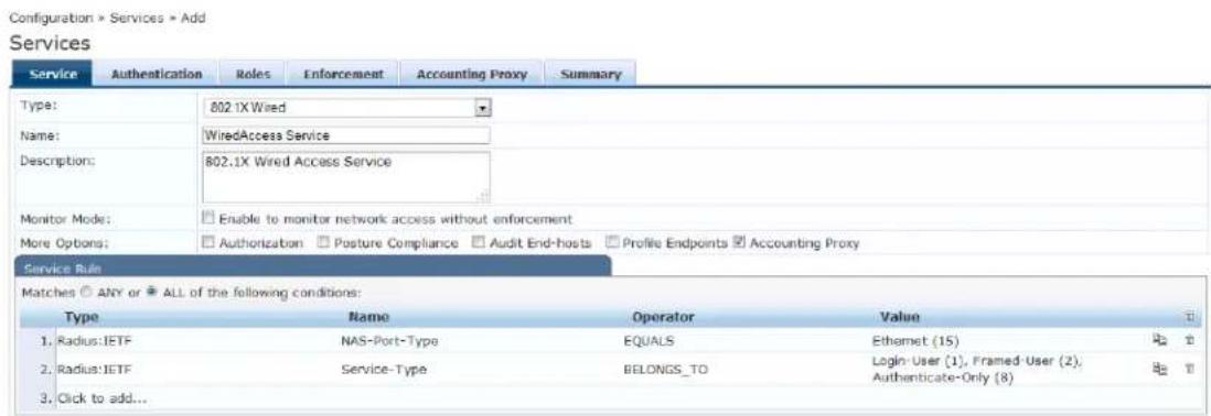
802.1X Wired—Identity Only Service
Configure this service for clients connecting through an Ethernet LAN with authentication using IEEE 802.
Configuration for the 802.1X Wired—Identity Only service is same as the 802.1X Wired service, except that Posture and Audit policies are not configurable when you use this template.
For more information, see 802.1X Wired Service on page 72.
The following figure displays the 802.1X Wired—Identity Only Service dialog:
Figure 34: 802.1X Wired—Identity Only Service
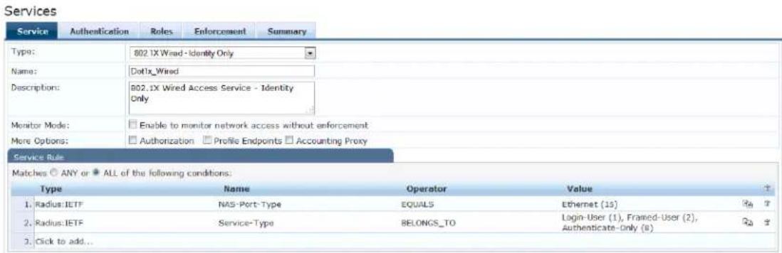
Dell 802.1X Wireless Service
This section provides the following information:
• Service Configuration on page 74
• Authentication Configuration on page 76
• Roles Configuration on page 79
• Enforcement Configuration on page 80
• Summary Information on page 84
You can configure the following additional Dell 802.1X Wireless Service parameters by checking the appropriate More Options check box:
• Authorization Configuration on page 77
• Posture Configuration on page 79
• Audit Configuration on page 81
• Profile Endpoints Configuration on page 82
• Accounting Proxy Configuration on page 83
Configure this service for wireless hosts that are connecting through a Dell 802.1X wireless access device controller using IEEE 802.1X authentication.
Service rules are customized for a typical Dell W-Series Controller deployment.
The Dell WLANW-Series 802.1X service includes a rule that specifies that a Dell ESSID exists.
The following figure displays the Add Dell 802.1X Wireless Service dialog:
Figure 35: Add Dell 802.1X Wireless Service Dialog
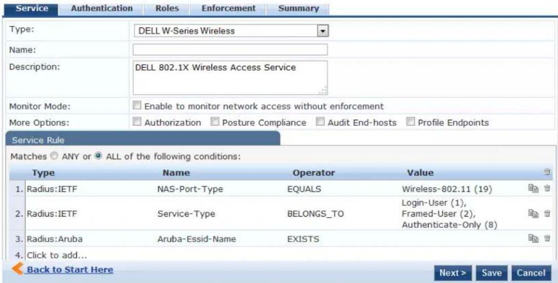
Service Configuration
The Service tab provides basic configuration parameters for the service.
The Service Rules section defines a set of criteria that supplicants must match to trigger the service. Some service templates have one or more rules predefined.
You can click on a service rule to modify any of its options.
Figure 36: Add Dell 802.1X Wireless Service > Service Dialog
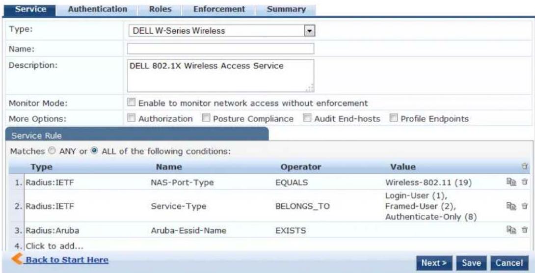
- Specify the Service tab parameters as described in the following table:
Table 21: Add Dell 802.1X Wireless Service > Service Tab Parameters
| Parameter Action/Description | |
| Type Select a service from | the drop-down list that defines what type of service can be configured. |
| Name Enter the name of the service. | |
| Description Provide additional information that helps to identify the service. | |
| Monitor Mode Select this check box to monitor network access activity without enforcement. | |
| More Options Check these | boxes to access the additional configuration tabs: AuthorizationPosture Compliance |
| Service Rule | |
| Type Select the service rule type. | |
| Name Select the name of the service rule from the drop-down list. | |
| Operator | Select an appropriate operator from the list of operators for the data type of attribute.For example, you can select from BELONGS_TO, NOT_BELONGS_TO, CONTAINS, EQUALS. |
| Value | Select the value from the drop-down list. The value list depends on the opera selected. |
Service rules define a set of criteria that supplicants must match to trigger the service. Some service templates have one or more rules predefined.
- Click a service rule to modify its options.

If you want to administer the same set of policies for wired and wireless access, you can combine the service rule define one single service. The other option is to keep two services for wired and wireless access, but reuse the poli components (authentication methods, authentication source, authorization source, role mapping policies, posture policies, and enforcement policies) in both services.
Authentication Configuration
The Authentication tab contains options for configuring authentication methods and authentication sources.
The following figure displays the Authentication dialog:
Figure 37: Add Dell 802.1X Wireless Service > Authentication Dialog
![Configuration » Services » Add Services Service Authentication Rules Enforcement Summary Authentication Methods: [EAP PEAP] [EAP FAST] [EAP TLS] [EAP TTLS] Move Up Move Down Remove View Details Modify Add new Authentication Method --Select to Add-- Authentication Sources: Move Up Move Down Remove View Details Modify --Select to Add-- Strip Username Rules: Enable to specify a comma-separated list of rules to strip username prefixes or suffixes Add new Authentication Source](/content/2026/05/842116/images/dff1d7dc78ae7ea1cbfc2b7f0a368fcfbe587047baca52f69192d5a02d030e81.jpg)
- Specify the Authentication tab parameters as described in the following table:
Table 22: Add Dell 802.1X Wireless Service > Authentication Parameters
| Parameter Action/Description | |
| Authentication Methods | Select authentication methods using the Select to Add field used for this service depend on the 802.1X supplicants and the type of authentication methods you choose to deploy.Policy Manager automatically selects the appropriate method for authentication, when a user attempts to connect. The common types, which are automatically selected include the following examples:EAP PEAPEAP FASTEAP TLSEAP TTLSEAP MSCHAPV2The EAP-MD5 authentication type is not supported if you use W-ClearPass Policy Manager in FIPS mode.The order of authentication is significant, when a client tries to perform an 802.1X authentication.Policy Manager proposes the first authentication method configured. However, the client can accept the authentication method proposed by Policy Manager and continue authentication or send a Negative-Acknowledgment (NAK) and propose a different authentication method. If the newly proposed authentication method is also configured, then the authentication proceeds, otherwise authentication fails.If most of the clients in the network use a specific authentication method, that authentication method should be configured first in the list. This would reduce the number of RADIUS packets exchanged.For more information, see the following:Adding and Configuring Authentication Methods on page 183Adding and Configuring Authentication Sources on page 207. |
| Authentication Sources | Specify the authentication sources using the Select to Add field.This can be one or more instances of the following list of authentication sources:avenda313 [Active Directory]Admin User RepositoryBlacklist User RepositoryEndpoints RepositoryGuest Device RepositoryGuest User RepositoryInsight RepositoryLocal User RepositoryOnboard Devices RepositorySocial Login RepositoryTime SourceNOTE:When you attempt to specify more than 23 Services authentication sources, the following error message is displayed:No. of Authentication Sources cannot exceed 23. |
| StripUsernameRules | Select the check box to preprocess the user name (to remove prefixes and suffixes) before authenticating and authorizing against the authentication source. |
Authorization Configuration
Use the Authorization tab to select the authorization sources for this service.
The Authorization tab is not displayed by default. To access this tab, select the More Options > Authorization check box.
W-ClearPass fetches role-mapping attributes from the authorization sources associated with the service, regardless of which authentication source was used to authenticate the user.
For a given service, role-mapping attributes are fetched from the following authorization sources:
• Authorization sources associated with the authentication source
• Authorization sources associated with the service
The following figure displays the Authorization dialog:
Figure 38: Add Dell 802.1X Wireless Service > Authorization Dialog
![Configuration > Services > Add Services Service Authentication Authorization Roles Enforcement Summary Authorization Details: Authorization sources from which role mapping attributes are fetched (for each Authentication Source) Authentication Source Attributes Fetched From 1. [Admin User Repository] [Local SQL DB] [Admin User Repository] [Local SQL DB] 2. [Blacklist User Repository] [Local SQL DB] [Blacklist User Repository] [Local SQL DB] Additional authorization sources from which to fetch role-mapping attributes - Event313 (Active Directory) Remove View Details Modify Select to Add- Add new Authentication Source](/content/2026/05/842116/images/6933193d8dae00129c436dd85b0841b0e826c0c90904855b49d0c552fc0966b5.jpg)
- Specify the Authorization parameters as described in the following table:
Table 23: Add Dell 802.1X Wireless Service > Authorization Parameters
| Parameter Action/Description | |
| Authentication Source Displays the authorization sources from which role mapping attributes are fetched for each authentication source. | |
| Attributes Fetched From | Displays the source of attributes. |
| Additional authorization sources from which to fetch role-mapping attributes | Specify the authorization sources using the Select to Add field.This can be one or more instances of the following list of authorization sources:Admin User Repositoryavenda313 [Active Directory]Blacklist User RepositoryEndpoints RepositoryGuest Device RepositoryGuest User RepositoryInsight RepositoryLocal User RepositoryOnboard Devices RepositorySocial Login RepositoryTime SourceNOTE:When you attempt to specify more than 23 Services authorization sources, the following error message is displayed:No. of Authorization Sources cannot exceed 23. |
For more information on configuring authorization sources, see Adding and Configuring Authentication Methods on page 183.
Roles Configuration
Use the Roles tab to associate a role-mapping policy with this service.
The following figure displays the Dell 802.1X Wireless Service > Roles dialog:
Figure 39: Add Dell 802.1X Wireless Service > Roles Dialog
![Configuration » Services » Add Services Service Authentication Authorization Roles Enforcement Summary Role Mapping Policy: [Guest Roles] Modify Add new Role Mapping Policy Role Mapping Policy Details Description: The roles used by Guest. Default Role: [Employee] Rules Evaluation Algorithm: first-applicable Conditions Role 1. (GuestUser:Role ID EQUALS 1) [Contractor] 2. (GuestUser:Role ID EQUALS 2) [Guest] 3. (GuestUser:Role ID EQUALS 3) [Employee]](/content/2026/05/842116/images/405a12dfd79a14dafae6ff9e482fdc7514eeae73070a7f2f33fcbc36431b579a.jpg)
- Specify the Roles parameters as described in the following table:
Table 24: Add Dell 802.1X Wireless Service > Roles Tab Parameters
| Parameter Action/Description | |
| Role Mapping Policy Select a role mapping policy from the drop-down list.Policy Manager ships a number of preconfigured roles.NOTE: A service can be configured without a role-mapping policy, but only role-mapping policy can be configured for each service. | |
| Role Mapping Policy Details | |
| Description Provide additional information about the selected role-mapping policy. | |
| Default Role Specify the role to which Policy Manager defaults when the role-mapping policy does not produce a match. | |
| Rules Evaluation Algorithm Shows the first matched rule. |
For information on configuring role-mapping policies, see Configuring a Role and Role-Mapping Policy on page 272.
Posture Configuration
The Posture tab is not enabled by default. To enable posture checking for this service:
- Select the More Options > Posture Compliance check box.
You can enable the posture checking for this kind of service, if you deploy any of the following:
■ W-ClearPass Policy Manager in a Microsoft Network Access Protection (NAP)
■ Cisco Network Admission Control (NAC) Framework environment
■ Dell hosted captive portal that performs posture checks through a dissolvable agent

The Posture tab cannot be enabled when High Capacity Guest mode is enabled in the W-ClearPass cluster.
The following figure displays the Posture dialog:
Figure 40: Add Dell 802.1X Wireless Service > Posture Dialog
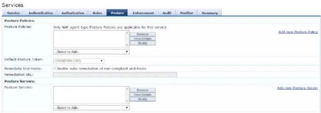
- Specify the Wireless Service Posture parameters as described in Table 25:
Table 25: Add Dell 802.1X Wireless Service > Posture Parameters
| Parameter Action/Description | |
| Posture Policies | |
| Posture Policies | Select the posture policy from the Select to Add drop-down list.If you do not have any preconfigured posture policies, click Add New Posture Policy to create a new posture policy.NOTE: Only NAP agent-type posture policies are applicable for this service. |
| Default Posture Token Select | the default posture token from the drop-down list. |
| Remediate End-Hosts | To perform remediation action, when a client is quarantined, select the Enable auto-remediation of non-compliant end-hosts check box. |
| Remediation URL | To perform the remediation, enter the web link of a server resource. |
For more information on configuring posture polices, see Configuring Posture Policy Agents and Hosts on page 285.
Enforcement Configuration
Use this tab to select an enforcement policy for a service. The following figure displays the Enforcement dialog:
Figure 41: Dell 802.1X Wireless Service > Enforcement Dialog
![Configuration * Services * Add Services Service Authentication Roles Enforcement Summary Use Cached Results: Use cached Roles and Posture attributes from previous sessions Enforcement Policy: [Sample Allow Access Policy] Modify Add new Enforcement Policy Enforcement Policy Details Description: Sample policy to allow network access Default Profile: [Allow Access Profile] Rules Evaluation Algorithm: evaluate-all Conditions Enforcement Profiles 1. (Date:Day of-Week BELONGS TO Monday, Tuesday, Wednesday, Thursday, Friday, Saturday, Sunday) [Allow Access Profile]](/content/2026/05/842116/images/a3e695b8a085d41347735d7d3bb086ac320a16effac8f85062750bbe059e6e57.jpg)
- Specify the Enforcement parameters as described in the following table:
Table 26: Dell 802.1X Wireless Service > Enforcement Parameters
| Parameter Action/Description | |
| Use Cached Results Select this | check box to use cached roles and posture attributes from previous sessions. |
| Enforcement Policy Select the | preconfigured enforcement policy from the drop-down list. This is mandatory.If you do not have any preconfigured enforcement policies, click Add New Enforcement Policy to create a new enforcement policy. |
| Enforcement Policy Details | |
| Description Displays additional | information about the selected enforcement policy. |
| Default Profile Displays a default | profile applied by W-ClearPass Policy Manager. |
| Rules Evaluation Algorithm Shows the first matched rule. | |
For more information, see Configuring Enforcement Policies on page 371.
Audit Configuration
Use the Audit tab to enable the Audit checking for this service.
- To enable the Audit tab, select the Audit End-hosts check box from the More Options field on the Service tab.
The Audit dialog opens.
Figure 42: Add Dell 8021X Wireless Service > Audit Dialog
![Configuration > Services > Add Services Service Authentication Roles Enforcement Audit Summary Audit Server: [Nmap Audit] View Details Modify Add new Audit Server Audit Trigger Conditions: Always When posture is not available For MAC authentication request For known end-hosts only For unknown end-hosts only For all end-hosts Action after audit: No Action Do SNMP bounce Trigger RADIUS CoA action [Aerohive - Terminate Session] View Details Modify Add new RADIUS CoA Action](/content/2026/05/842116/images/6fdccb728ebf0caaa0673b5c3f1c5b64b1dabcc1d974c1602813ef32d806eea2.jpg)
- Specify the Audit End-Hosts parameters as described in the following table:
Table 27: Add Dell 802.1X Wireless Service > Audit End-Hosts Parameters
| Parameter Action/Description | |
| Audit Server Select the audit server from the following options:Nessus Server: Interfaces with Policy Manager primarily to perform vulnerability scanning.Nmap Audit: Performs specific Nmap audit functions.To view thePolicy Manager Entity Detailsdialog with the summary of audit server details, click theView Detailsbutton.To view theSummarytab with audit server details, click theModifybutton. | |
| Audit Trigger Conditions Select an audit trigger condition:Always: Always perform an audit.When posture is not available: Perform audit only when posture credentials are not available in the request.For MAC Authentication Request: If you select this option, Policy Manager presents the following three additional settings:For known end-hosts only: Select this option when you want to reject unknown end-hosts and to audit known clients. Known end-hosts are defined as clients that are found in the authentication source(s) associated with this service.For unknown end-hosts only: Select this option when the known end-hosts are assumed to be healthy, but you want to establish the identity of unknown end-hosts and assign roles. Unknown end-hosts are end-hosts that are not found in any of the authentication sources associated with this service.For all end-hosts: For both known and unknown end-hosts. | |
| Action After Audit | Specify the audit that can be performed only after the MAC authentication request is completed and the client has acquired an IP address through DHCP.Once the audit results are available, Policy Manager reapplies policies on the network device in one of the following ways:No Action: The audit does not apply policies on the network device after completing this audit.Do SNMP bounce: This option bounces the switch port or forces an 802.1X reauthentication (both done using SNMP).Bouncing the port triggers a new 802.1X or MAC authentication request by the client. If the audit server already has the posture token and attributes associated with this client in its cache, it returns the token and the attributes to W-ClearPass.Trigger RADIUS CoA action: This option sends a RADIUS CoA command from W-ClearPass to the network device. |
Profile Endpoints Configuration
The Profiler tab is not displayed by default. To access this tab, select the More Options > Profile Endpoints check box.
The Add Profile Endpoints dialog opens:
Figure 43: Add Dell 802.1X Wireless Service > Profile Endpoints Dialog
![Configuration > Services > Add Services Service Authentication Roles Enforcement Profiler Summary Endpoint Classification: Select the classification(s) after which an action must be triggered - Game Console Network Camera Remove -- Select -- RADIUS CoA Action: [Aruba Terminate Session] View Details Modify Add new RADIUS CoA Action](/content/2026/05/842116/images/b14ec98b0f826272656dcc6b624ea3f88485a80ff4e6ed6ac26cfa7174380b25.jpg)
- Specify the Profile Endpoints parameters as described in the following table:
Table 28: Add Dell 802.1X Wireless Service > Profile Endpoints Parameters
| Parameter Action/Description | |
| Endpoint Classification Select one or more endpoint classification items from the drop-down list. | |
| RADIUS CoA Action Select the RADIUS CoA action from the drop-down list.To view the Policy Manager Entity Details page with the summary of enforcement profile details, click the View Details button.To view the Summary tab with profile details, click the Modify button.To create a new RADIUS CoA action, click the Add New RADIUS CoA Action link. |
Accounting Proxy Configuration
Use the Accounting Proxy tab to broadcast the RADIUS accounting packets to all the proxy targets.
You can configure the proxy targets to which RADIUS server should be forwarded and the attributes to added in the accounting. This enables the external security solutions to use the RADIUS account event to detect when a user connects and disconnects to the server.
- To enable the Accounting Proxy tab, select the More Options > Accounting Proxy check box. The following figure displays the Add Accounting Proxy dialog:
Figure 44: Add 802.1X Wireless > Accounting Proxy Dialog
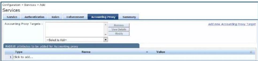
- Specify the Accounting Proxy parameters as described in the following table:
Table 29: Add Dell 802.1X Wireless Service > Accounting Proxy Tab Parameters
| Parameter Action/Description | |
| Accounting Proxy Targets Specify the proxy targets to which the RADIUS server should be forwarded and the attributes to be added in the accounting.Select the accounting proxy target from the Select to Add drop-down list. | |
| Add New Accounting Proxy Target | Click this link to add a new accounting proxy target. |
| RADIUS attributes to be added for Accounting Proxy | |
| Type Select the RADIUS attribute type from the drop-down list:Radius:IETFRadius:Ciscoradius:Hewlett-Packard-EnterpriseRadius:Alcatel-Lucent-EnterpriseRadius:MicrosoftRadius:AvendaRadius:Dell | |
| Name | Select the name of the RADIUS attribute from the drop-down list. |
| Value | Select the value from the Value drop-down list.The values displayed here depend on the RADIUS attribute Type selected. |
Summary Information
The Summary page presents the summary of parameters defined when you created a new service.
802.1X Wireless—Identity Only Service
Configuration for this type of service is the same as the Dell 802.1X Wireless Service, except that Posture and Audit policies are not configurable when you use this template.
For more information, see 802.1X Wireless Service on page 1.
The following figure displays the Configuration > Services > Add 802.1X Wireless—Identity Only Service dialog:
Figure 45: 802.1X Wireless—Identity Only Service Dialog
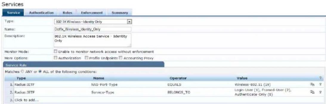
Dell 802.1X Wireless Service
This section provides the following information:
• Service Configuration on page 85
• Authentication Configuration on page 87
- Roles Configuration on page 90
• Enforcement Configuration on page 91
• Summary Information on page 95
You can configure the following additional Dell 802.1X Wireless Service parameters by checking the appropriate More Options check box:
• Authorization Configuration on page 88
• Posture Configuration on page 90
• Audit Configuration on page 92
• Profile Endpoints Configuration on page 93
• Accounting Proxy Configuration on page 94
Configure this service for wireless hosts that are connecting through a Dell 802.1X wireless access device controller using IEEE 802.1X authentication.
Service rules are customized for a typical Dell W-Series Controller deployment.
The Dell WLANW-Series 802.1X service includes a rule that specifies that a Dell ESSID exists.
The following figure displays the Add Dell 802.1X Wireless Service dialog:
Figure 46: Add Dell 802.1X Wireless Service Dialog
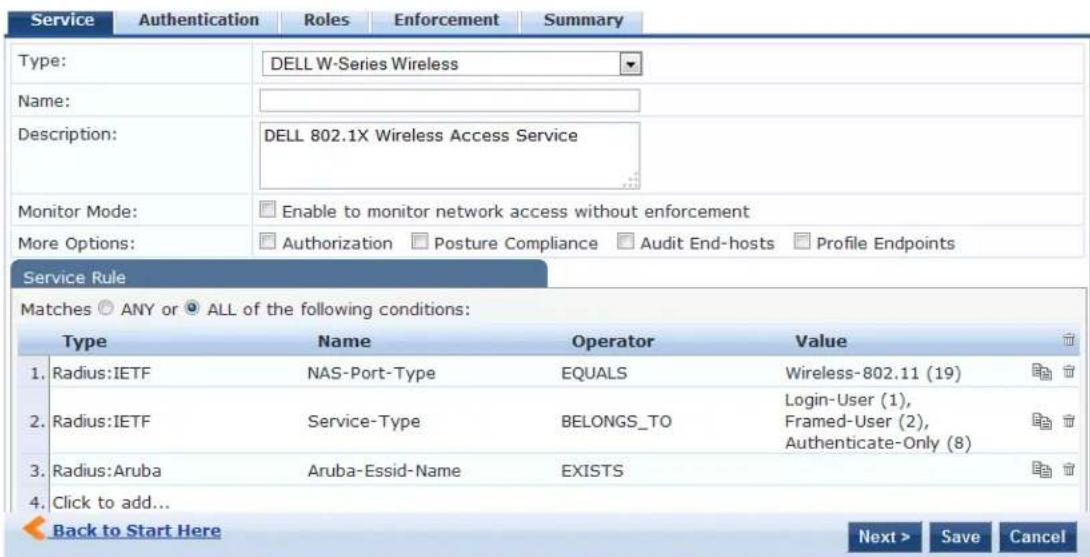
Service Configuration
The Service tab provides basic configuration parameters for the service.
The Service Rules section defines a set of criteria that supplicants must match to trigger the service. Some service templates have one or more rules predefined.
You can click on a service rule to modify any of its options.
Figure 47: Add Dell 802.1X Wireless Service > Service Dialog
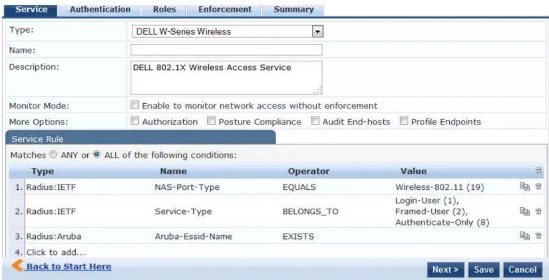
- Specify the Service tab parameters as described in the following table:
Table 30: Add Dell 802.1X Wireless Service > Service Tab Parameters
| Parameter Action/Description | |
| Type Select a service from | the drop-down list that defines what type of service can be configured. |
| Name Enter the name of the service. | |
| Description Provide additional information that helps to identify the service. | |
| Monitor Mode Select this check box to monitor network access activity without enforcement. | |
| More Options | Check these boxes to access the additional configuration tabs: AuthorizationPosture Compliance |
| Service Rule | |
| Type Select the service rule type. | |
| Name Select the name of the service rule from the drop-down list. | |
| Operator | Select an appropriate operator from the list of operators for the data type of attribute.For example, you can select from BELONGS_TO, NOT_BELONGS_TO, CONTAINS, EQUALS. |
| Value | Select the value from the drop-down list. The value list depends on the opera selected. |
Service rules define a set of criteria that supplicants must match to trigger the service. Some service templates have one or more rules predefined.
- Click a service rule to modify its options.

If you want to administer the same set of policies for wired and wireless access, you can combine the service rule define one single service. The other option is to keep two services for wired and wireless access, but reuse the poli components (authentication methods, authentication source, authorization source, role mapping policies, posture policies, and enforcement policies) in both services.
Authentication Configuration
The Authentication tab contains options for configuring authentication methods and authentication sources.
The following figure displays the Authentication dialog:
Figure 48: Add Dell 802.1X Wireless Service > Authentication Dialog
![Configuration » Services » Add Services Service Authentication Rules Enforcement Summary Authentication Methods: [EAP PEAP] [EAP FAST] [EAP TLS] [EAP TTLS] Move Up Move Down Remove View Details Modify Add new Authentication Method --Select to Add-- Authentication Sources: Move Up Move Down Remove View Details Modify --Select to Add-- Strip Username Rules: Enable to specify a comma-separated list of rules to strip username prefixes or suffixes Add new Authentication Source](/content/2026/05/842116/images/55f08942eea3df7cf8467bcf445ea6ab0652f5c158f77acedafdeeedeb36189f.jpg)
- Specify the Authentication tab parameters as described in the following table:
Table 31: Add Dell 802.1X Wireless Service > Authentication Parameters
| Parameter Action/Description | |
| Authentication Methods | Select authentication methods using the Select to Add field used for this service depend on the 802.1X supplicants and the type of authentication methods you choose to deploy.Policy Manager automatically selects the appropriate method for authentication, when a user attempts to connect. The common types, which are automatically selected include the following examples:EAP PEAPEAP FASTEAP TLSEAP TTLSEAP MSCHAPV2The EAP-MD5 authentication type is not supported if you use W-ClearPass Policy Manager in FIPS mode.The order of authentication is significant, when a client tries to perform an 802.1X authenticationPolicy Manager proposes the first authentication method configured. However, the client can accept the authentication method proposed by Policy Manager and continue authentication or send a Negative-Acknowledgment (NAK) and propose a different authentication method. If the newly proposed authentication method is also configured, then the authentication proceeds, otherwise authentication fails.If most of the clients in the network use a specific authentication method, that authentication method should be configured first in the list. This would reduce the number of RADIUS packets exchanged.For more information, see the following:Adding and Configuring Authentication Methods on page 183Adding and Configuring Authentication Sources on page 207. |
| Authentication Sources | Specify the authentication sources using the Select to Add field.This can be one or more instances of the following list of authentication sources:avenda313 [Active Directory]Admin User RepositoryBlacklist User RepositoryEndpoints RepositoryGuest Device RepositoryGuest User RepositoryInsight RepositoryLocal User RepositoryOnboard Devices RepositorySocial Login RepositoryTime SourceNOTE:When you attempt to specify more than 23 Services authentication sources, the following error message is displayed:No. of Authentication Sources cannot exceed 23. |
| StripUsernameRules | Select the check box to preprocess the user name (to remove prefixes and suffixes) before authenticating and authorizing against the authentication source. |
Authorization Configuration
Use the Authorization tab to select the authorization sources for this service.
The Authorization tab is not displayed by default. To access this tab, select the More Options > Authorization check box.
W-ClearPass fetches role-mapping attributes from the authorization sources associated with the service, regardless of which authentication source was used to authenticate the user.
For a given service, role-mapping attributes are fetched from the following authorization sources:
• Authorization sources associated with the authentication source
• Authorization sources associated with the service
The following figure displays the Authorization dialog:
Figure 49: Add Dell 802.1X Wireless Service > Authorization Dialog
![Configuration > Services > Add Services Service Authentication Authorization Roles Enforcement Summary Authorization Details: Authorization sources from which role mapping attributes are fetched (for each Authentication Source) Authentication Source Attributes Fetched From 1. [Admin User Repository] [Local SQL DB] [Admin User Repository] [Local SQL DB] 2. [Blacklist User Repository] [Local SQL DB] [Blacklist User Repository] [Local SQL DB] Additional authorization sources from which to fetch role-mapping attributes - Event313 (Active Directory) Remove View Details Modify Select to Add- Add new Authentication Source](/content/2026/05/842116/images/0bc31e0e579f9d78cc3f14d074287efb9f742afe90f9cef82fed0ca21e13f1ce.jpg)
- Specify the Authorization parameters as described in the following table:
Table 32: Add Dell 802.1X Wireless Service > Authorization Parameters
| Parameter Action/Description | |
| Authentication Source Displays the authorization sources from which role mapping attributes are fetched for each authentication source. | |
| Attributes Fetched From Displays the source of attributes. | |
| Additional authorization sources from which to fetch role-mapping attributes | Specify the authorization sources using the Select to Add field.This can be one or more instances of the following list of authorization sources:Admin User Repositoryavenda313 [Active Directory]Blacklist User RepositoryEndpoints RepositoryGuest Device RepositoryGuest User RepositoryInsight RepositoryLocal User RepositoryOnboard Devices RepositorySocial Login RepositoryTime SourceNOTE:When you attempt to specify more than 23 Services authorization sources, the following error message is displayed:No. of Authorization Sources cannot exceed 23. |
For more information on configuring authorization sources, see Adding and Configuring Authentication Methods on page 183.
Roles Configuration
Use the Roles tab to associate a role-mapping policy with this service.
The following figure displays the Dell 802.1X Wireless Service > Roles dialog:
Figure 50: Add Dell 802.1X Wireless Service > Roles Dialog
![Configuration » Services » Add Services Service Authentication Authorization Roles Enforcement Summary Role Mapping Policy: [Guest Roles] Modify Add new Role Mapping Policy Role Mapping Policy Details Description: The roles used by Guest. Default Role: [Employee] Rules Evaluation Algorithm: first-applicable Conditions Role 1. (GuestUser:Role ID EQUALS 1) [Contractor] 2. (GuestUser:Role ID EQUALS 2) [Guest] 3. (GuestUser:Role ID EQUALS 3) [Employee]](/content/2026/05/842116/images/e0e07844e74af37daddee1170beb6f2c96d81ccd7fdfb8b46466e4224a46605b.jpg)
- Specify the Roles parameters as described in the following table:
Table 33: Add Dell 802.1X Wireless Service > Roles Tab Parameters
| Parameter Action/Description | |
| Role Mapping Policy Select a role mapping policy from the drop-down list.Policy Manager ships a number of preconfigured roles.NOTE: A service can be configured without a role-mapping policy, but only one role-mapping policy can be configured for each service. | |
| Role Mapping Policy Details | |
| Description | Provide additional information about the selected role-mapping policy. |
| Default Role | Specify the role to which Policy Manager defaults when the role-mapping policy does not produce a match. |
| Rules Evaluation Algorithm | Shows the first matched rule. |
For information on configuring role-mapping policies, see Configuring a Role and Role-Mapping Policy on page 272.
Posture Configuration
The Posture tab is not enabled by default. To enable posture checking for this service:
- Select the More Options > Posture Compliance check box.
You can enable the posture checking for this kind of service, if you deploy any of the following:
■ W-ClearPass Policy Manager in a Microsoft Network Access Protection (NAP)
■ Cisco Network Admission Control (NAC) Framework environment
- Dell hosted captive portal that performs posture checks through a dissolvable agent

The Posture tab cannot be enabled when High Capacity Guest mode is enabled in the W-ClearPass cluster.
The following figure displays the Posture dialog:
Figure 51: Add Dell 802.1X Wireless Service > Posture Dialog
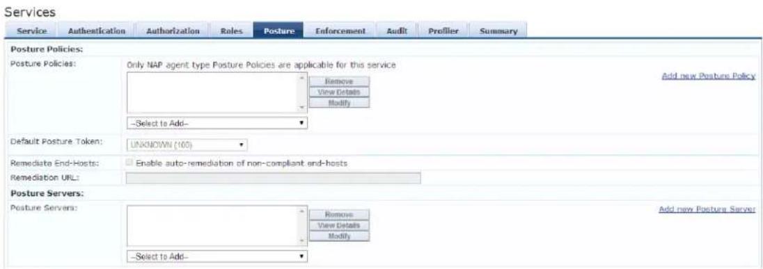
- Specify the Wireless Service Posture parameters as described in Table 34:
Table 34: Add Dell 802.1X Wireless Service > Posture Parameters
| Parameter Action/Description | |
| Posture Policies | |
| Posture Policies | Select the posture policy from the Select to Add drop-down list.If you do not have any preconfigured posture policies, click Add New Posture Policy to create a new posture policy.NOTE: Only NAP agent-type posture policies are applicable for this service. |
| Default Posture Token Select | the default posture token from the drop-down list. |
| Remediate End-Hosts | To perform remediation action, when a client is quarantined, select the Enable auto-remediation of non-compliant end-hosts check box. |
| Remediation URL To perform | the remediation, enter the web link of a server resource. |
For more information on configuring posture polices, see Configuring Posture Policy Agents and Hosts on page 285.
Enforcement Configuration
Use this tab to select an enforcement policy for a service. The following figure displays the Enforcement dialog:
Figure 52: Dell 802.1X Wireless Service > Enforcement Dialog
![Configuration > Services > Add Services Service Authentication Roles Enforcement Summary Use Cached Results: Use cached Roles and Posture attributes from previous sessions Enforcement Policy: [Sample Allow Access Policy] Modify Add new Enforcement Policy Enforcement Policy Details Description: Sample policy to allow network access Default Profile: [Allow Access Profile] Rules Evaluation Algorithm: evaluate-all Conditions Enforcement Profiles 1. (Date-Day-of-Week BELOW TO Monday, Tuesday, Wednesday, Thursday, Friday, Saturday, Sunday) [Allow Access Profile]](/content/2026/05/842116/images/4852369aa1a69aa1e1de561ad52ee657c682fe2b84ee3b45d7c985e8d68b2dc3.jpg)
- Specify the Enforcement parameters as described in the following table:
Table 35: Dell 802.1X Wireless Service > Enforcement Parameters
| Parameter Action/Description | |
| Use Cached Results Select this | check box to use cached roles and posture attributes from previous sessions. |
| Enforcement Policy Select the | preconfigured enforcement policy from the drop-down list. This is mandatory.If you do not have any preconfigured enforcement policies, click Add New Enforcement Policy to create a new enforcement policy. |
| Enforcement Policy Details | |
| Description Displays additional | information about the selected enforcement policy. |
| Default Profile | Displays a default profile applied by W-ClearPass Policy Manager. |
| Rules Evaluation Algorithm | Shows the first matched rule. |
For more information, see Configuring Enforcement Policies on page 371.
Audit Configuration
Use the Audit tab to enable the Audit checking for this service.
- To enable the Audit tab, select the Audit End-hosts check box from the More Options field on the Service tab.
The Audit dialog opens.
Figure 53: Add Dell 8021X Wireless Service > Audit Dialog
![Configuration > Services > Add Services Service Authentication Roles Enforcement Audit Summary Audit Server: [Nmap Audit] View Details Modify Add new Audit Server Audit Trigger Conditions: Always When posture is not available For MAC authentication request For known end-hosts only For unknown end-hosts only For all end-hosts Action after audit: No Action Do SNMP bounce Trigger RADIUS CoA action [Aerohive - Terminate Session] View Details Modify Add new RADIUS CoA Action](/content/2026/05/842116/images/ab172d31a12e640f20d2befc8185a48e5ee7841af15369e1fa8bba7b51eb5282.jpg)
- Specify the Audit End-Hosts parameters as described in the following table:
Table 36: Add Dell 802.1X Wireless Service > Audit End-Hosts Parameters
| Parameter Action/Description | |
| Audit Server Select the audit server from the following options:Nessus Server: Interfaces with Policy Manager primarily to perform vulnerability scanning.Nmap Audit: Performs specific Nmap audit functions.To view thePolicy Manager Entity Detailsdialog with the summary of audit server details, click theView Detailsbutton.To view theSummarytab with audit server details, click theModifybutton. | |
| Audit Trigger Conditions Select an audit trigger condition:Always: Always perform an audit.When posture is not available: Perform audit only when posture credentials are not available in the request.For MAC Authentication Request: If you select this option, Policy Manager presents the following three additional settings:For known end-hosts only: Select this option when you want to reject unknown end-hosts and to audit known clients. Known end-hosts are defined as clients that are found in the authentication source(s) associated with this service.For unknown end-hosts only: Select this option when the known end-hosts are assumed to be healthy, but you want to establish the identity of unknown end-hosts and assign roles. Unknown end-hosts are end-hosts that are not found in any of the authentication sources associated with this service.For all end-hosts: For both known and unknown end-hosts. | |
| Action After Audit Specify the audit that can be performed only after the MAC authentication request is completed and the client has acquired an IP address through DHCP.Once the audit results are available, Policy Manager reapplies policies on the network device in one of the following ways:No Action: The audit does not apply policies on the network device after completing this audit.Do SNMP bounce: This option bounces the switch port or forces an 802.1X reauthentication (both done using SNMP).Bouncing the port triggers a new 802.1X or MAC authentication request by the client. If the audit server already has the posture token and attributes associated with this client in its cache, it returns the token and the attributes to W-ClearPass.Trigger RADIUS CoA action: This option sends a RADIUS CoA command from W-ClearPass to the network device. |
Profile Endpoints Configuration
The Profiler tab is not displayed by default. To access this tab, select the More Options > Profile Endpoints check box.
The Add Profile Endpoints dialog opens:
Figure 54: Add Dell 802.1X Wireless Service > Profile Endpoints Dialog
![Configuration » Services » Add Services Service Authentication Roles Enforcement Profiler Summary Endpoint Classification: Select the classification(s) after which an action must be triggered - Game Console Network Camera Remove -- Select -- RADIUS CoA Action: [Aruba Terminate Session] View Details Modify Add new RADIUS CoA Action](/content/2026/05/842116/images/a141931235a87af09fecf9aff2012f483deb4f537aebc6c601941541090b3ff2.jpg)
- Specify the Profile Endpoints parameters as described in the following table:
Table 37: Add Dell 802.1X Wireless Service > Profile Endpoints Parameters
| Parameter Action/Description | |
| Endpoint Classification Select one or more endpoint classification items from the drop-down list. | |
| RADIUS CoA Action Select the RADIUS CoA action from the drop-down list.To view thePolicy Manager Entity Detailspage with the summary of enforcement profile details, click theView Details button.To view theSummarytab with profile details, click theModify button.To create a new RADIUS CoA action, click theAdd New RADIUS CoA Actionlink. |
Accounting Proxy Configuration
Use the Accounting Proxy tab to broadcast the RADIUS accounting packets to all the proxy targets.
You can configure the proxy targets to which RADIUS server should be forwarded and the attributes to added in the accounting. This enables the external security solutions to use the RADIUS account event to detect when a user connects and disconnects to the server.
- To enable the Accounting Proxy tab, select the More Options > Accounting Proxy check box. The following figure displays the Add Accounting Proxy dialog:
Figure 55: Add 802.1X Wireless > Accounting Proxy Dialog
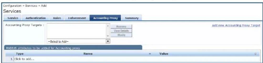
- Specify the Accounting Proxy parameters as described in the following table:
Table 38: Add Dell 802.1X Wireless Service > Accounting Proxy Tab Parameters
| Parameter Action/Description | |
| Accounting Proxy Targets Specify the proxy targets to which the RADIUS server should be forwarded and the attributes to be added in the accounting.Select the accounting proxy target from the Select to Add drop-down list. | |
| Add New Accounting Proxy Target | Click this link to add a new accounting proxy target. |
| RADIUS attributes to be added for Accounting Proxy | |
| Type Select the RADIUS attribute type from the drop-down list:Radius:IETFRadius:Ciscoradius:Hewlett-Packard-EnterpriseRadius:Alcatel-Lucent-EnterpriseRadius:MicrosoftRadius:AvendaRadius:Dell | |
| Name Select the name of the | RADIUS attribute from the drop-down list. |
| Value Select the value from the Value drop-down list.The values displayed here depend on the RADIUS attribute Type selected. | |
Summary Information
The Summary page presents the summary of parameters defined when you created a new service.
Cisco Web Authentication Proxy Service
This service is a web-based authentication service for guests or agent-less hosts.
The Cisco switch hosts a captive portal and the portal web page that collects username and password information. Subsequently, the switch sends a RADIUS request in the form of a Password Authentication Protocol (PAP) authentication request to Policy Manager.
By default, this service uses the PAP authentication method. You can click on the Authorization and Audit End-hosts options to enable additional tabs.
The following figure displays the Cisco Web Authentication Proxy service:
Figure 56: Cisco Web Authentication Proxy Service
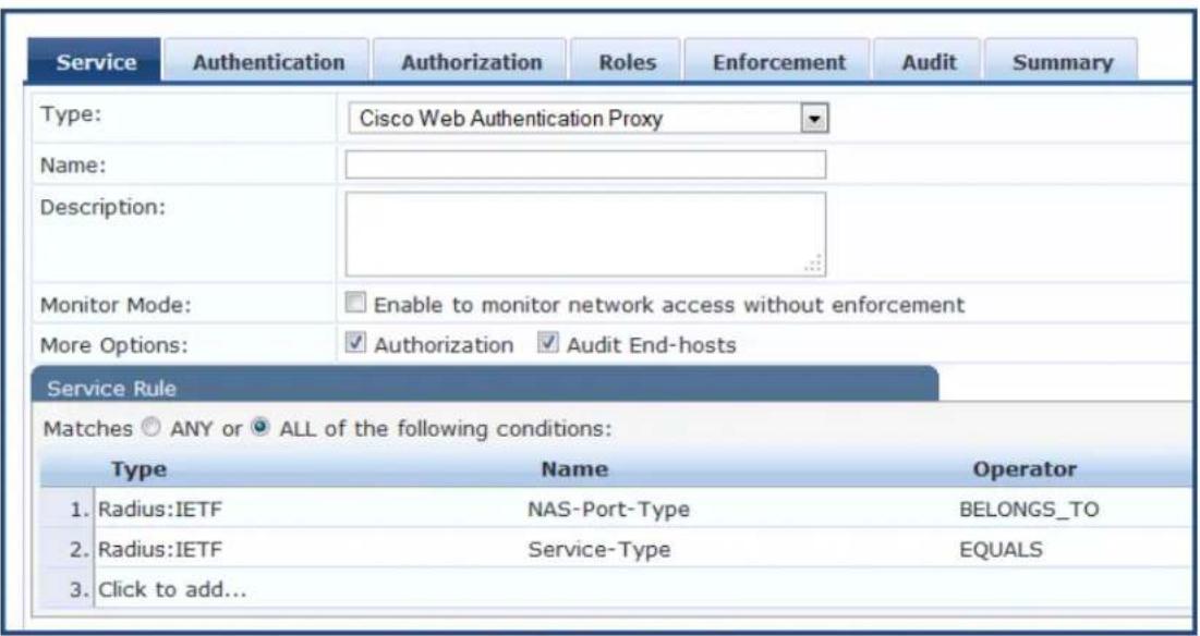
Configuring the Cisco Web Authentication Proxy service is similar to configuring the Dell 802.1X Wireless service except that the Posture Compliance and Profile Endpoints options are not available. For more information on configuration, see Dell 802.1X Wireless Service on page 85.
MAC Authentication Service
The MAC-based authentication service is used for clients without an 802.1X supplicant or a posture agent as printers, other embedded devices, and computers owned by guests or contractors).
The network access device sends a MAC authentication request to Policy Manager. Policy Manager can lo the client in a white list or a black list, authenticate, and authorize the client against an external authen or authorization source, and optionally perform an audit on the client.
You cannot configure posture for this type of service.

The following figure displays the MAC Authentication service configuration dialog.
Figure 57: MAC Authentication Service Configuration Dialog
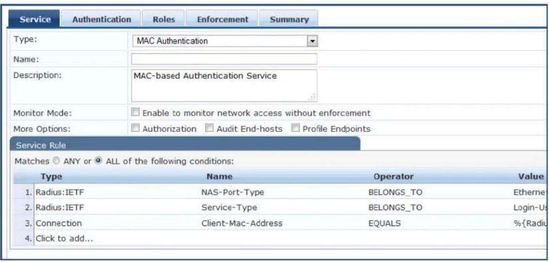
The Posture tab is not available for the MAC-based authentication service.
Configuration for the rest of the tabs is similar to the Dell 802.1X Wireless service configuration. For details on this service's configuration, see Dell 802.1X Wireless Service on page 85.
RADIUS Authorization Service
Configure the RADIUS Authorization service type for services that perform authorization using RADIUS.
When you select this service, the Authorization tab is enabled. The following figure displays the RADIUS Authorization service configuration dialog:
Figure 58: RADIUS Authorization Service Configuration Dialog
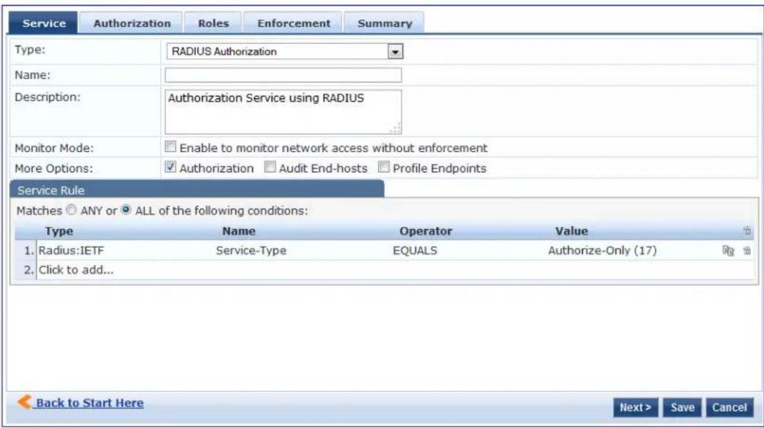
Configuration for this service is the same as the RADIUS Enforcement (Generic) service, except that you do not configure authentication or posture with this service type. Refer to RADIUS Enforcement (Generic) Service on page 98 for more information.
RADIUS Enforcement (Generic) Service
Configure the RADIUS Enforcement (Generic) service for any kind of RADIUS request.

The AirGroup Authorization Service service is the only RADIUS Enforcement (Generic) service that is available by default.
In addition to the default configuration tabs (Service, Authentication, Roles, and Enforcement), from More Options you can also enable the Authorization, Posture Compliance, Audit End Hosts, and Profile Endpoints tabs.
There are no default rules associated with this service type. You can add Rules to handle any type of si or vendor-specific RADIUS attributes (that is, any attribute that is loaded through the prepackaged vendor specific or standard RADIUS dictionaries, or through other dictionaries imported into Policy Manager).
The following figure displays the RADIUS Enforcement (Generic) service configuration dialog:
Figure 59: RADIUS Enforcement (Generic) Service Configuration Dialog
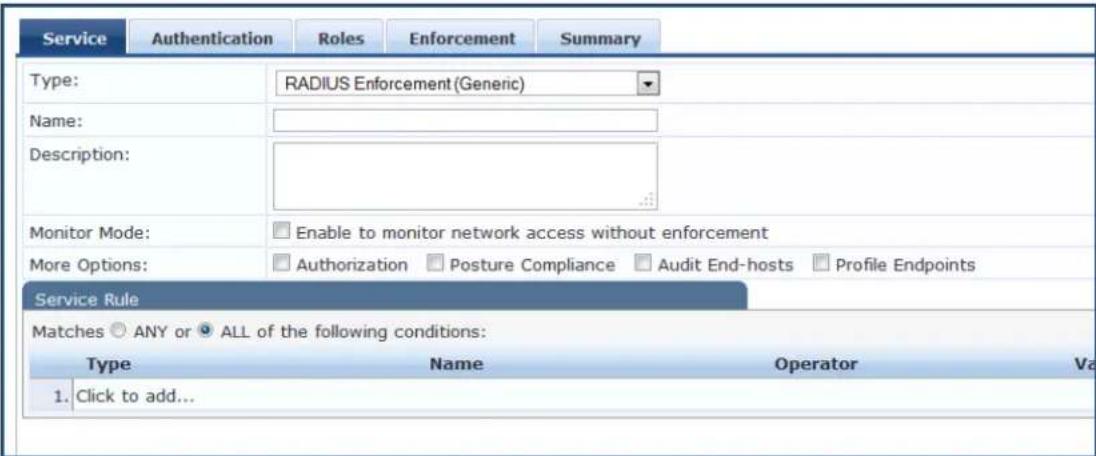
Configuring a service for RADIUS requests is similar to configuring the Dell 802.1X Wireless service. For details, see Dell 802.1X Wireless Service on page 85.
RADIUS Proxy Service
Configure the RADIUS Proxy service for any kind of RADIUS request that needs to be proxied to another RADIUS server (that is, a proxy target).
There are no default rules associated with this service type. You can add rules to handle any type of st or vendor-specific RADIUS attributes. Typically, proxying is based on the realm or the domain of the user is trying to access the network.
Configuration of this service is the same as the RADIUS Enforcement (Generic) service except that you do not configure Authentication or Posture policies with this service type.
However, you need to configure proxy targets (the servers to which requests are proxied). Requests can dispatched to the proxy targets randomly, and are load balanced.
However, in Failover mode, requests can be dispatched to the first proxy target in the ordered list of targets and subsequently to the other proxy targets if the prior requests failed.
When you select the Enable proxy for accounting requests, accounting requests are also sent to the proxy targets.
The following figure displays the RADIUS Proxy service configuration dialog:
Figure 60: RADIUS Proxy Service Configuration Dialog
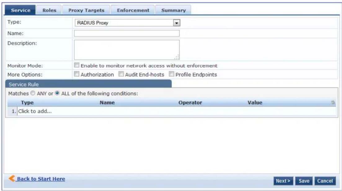
For configuration details, see RADIUS Enforcement (Generic) Service on page 98.
Dell W-Series Application Authentication Service
This type of service provides authentication and authorization to users of W-Series W-ClearPass Guest and Series W-ClearPass Insight.
You can send Generic Application Enforcement Profile on page 405 to these or other generic applications for authenticating and authorizing the users.
The following figure displays the Dell W-Series Application Authentication service configuration dialog:
Figure 61: Dell W-Series Application Authentication Configuration Dialog
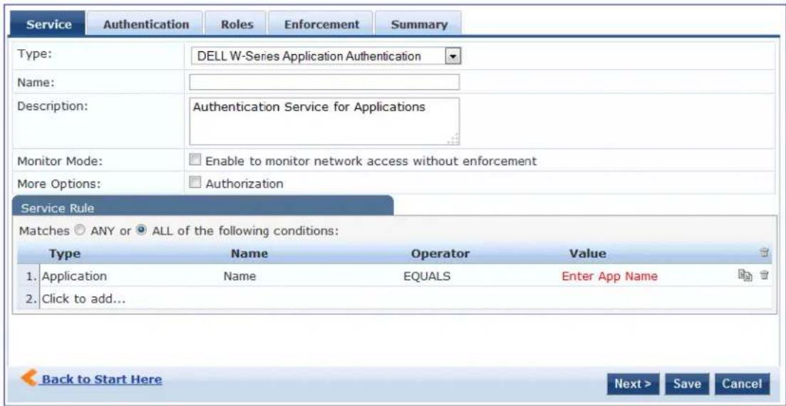
Configuring the Dell W-Series Application Authentication service is similar to configuring the Dell 802.1X Wireless service except that the Posture Compliance, Audit End-hosts, and Profile Endpoints options are not available.
For configuration details, see Dell 802.1X Wireless Service on page 85.
Dell W-Series Application Authorization Service
This type of service provides authorization for users of Dell applications: W-Series W-ClearPass Guest and Series W-ClearPass Insight.
You can send Generic Application Enforcement Profile on page 405 to these or other generic applications for authorizing the users.
The following figure displays the Dell W-Series Application Authorization service configuration dialog:
Figure 62: Dell W-Series Application Authorization Configuration Dialog
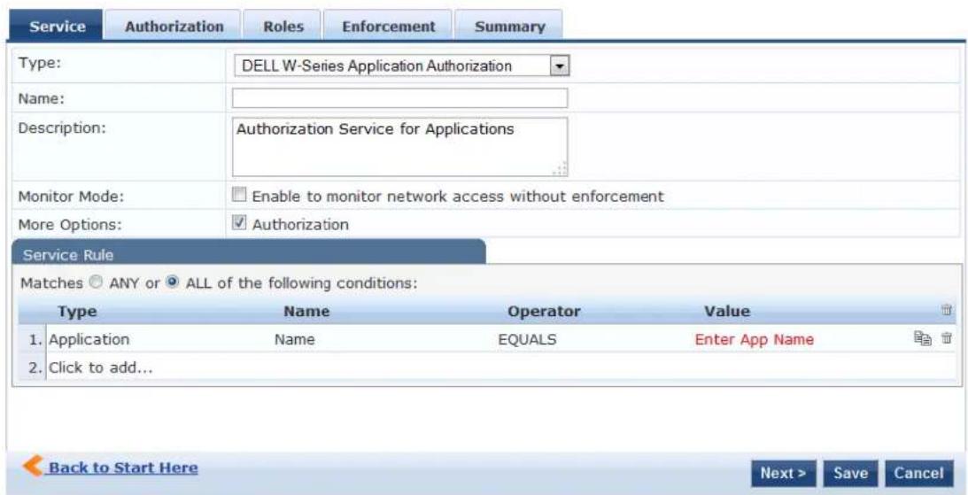
Configuring the Dell W-Series Application Authorization service is similar to configuring the Dell 802.1X Wi service except that the Posture Compliance, Audit End-hosts, and Profile Endpoints options are not available.
For configuration details, see Dell 802.1X Wireless Service on page 85.
W-ClearPass OnConnect Enforcement Service
This section provides the following information:
- Adding a W-ClearPass OnConnect Enforcement Service
• Associating the W-ClearPass OnConnect Service with an Enforcement Policy
W-ClearPass OnConnect Enforcement is an enforcement model that allows you to use non-802.1X methods for device scans, VLAN placement, and so on. W-ClearPass OnConnect Enforcement allows enforcement in non-802.1X environments without the need for an agent, such as OnGuard, on the endpc
For related information, see:
- Enabling W-ClearPass OnConnect Enforcement on a Network Device on page 470
- OnConnect Setting on page 500
When W-ClearPass OnConnect Enforcement is enabled, W-ClearPass performs the following actions:
• Detects when a new endpoint connects to the network.
- Scans the endpoint to identify the logged-in user and other device-specific information.
- Triggers a Web-based authentication (WebAuth) for the device.
• Performs SNMP-based enforcement to change the network access profile for the device.
Adding a W-ClearPass OnConnect Enforcement Service
To add an OnConnect Enforcement service:
- Navigate to Configuration > Services.
The Services page opens.
- To add the service, click Add.
The Add Services dialog opens.
- From the Type drop-down list, select W-ClearPass OnConnect Enforcement (see Figure 63).
Figure 63: Specifying W-ClearPass OnConnect Enforcement
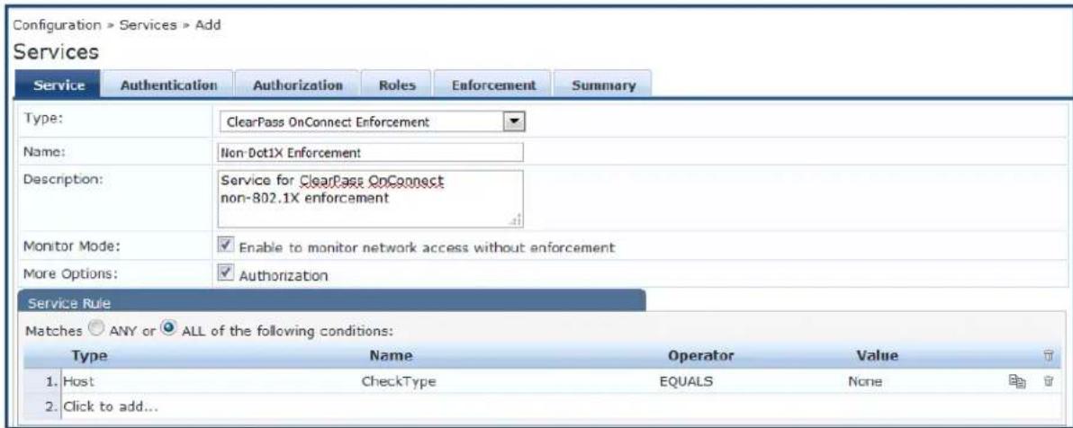
-
Enter the name or label of the OnConnect Enforcement service.
-
Enter the values for any other parameters, including service rules, required for this service.
For a description of all the parameters in the Service page, see Adding Services on page 1.
Associating the W-ClearPass OnConnect Service with an Enforcement Policy
After you create the W-ClearPass OnConnect Enforcement service, you must associate the service with an enforcement policy.
WMI (Windows Management Instrumentation) configuration is used to retrieve the Loggedin User information.
Whenever a domain-joined Windows client connects to an OnConnect-enabled port with the domain user logged in, Authorization attributes for this user are fetched from authorization sources to determine the the user; this information is then used in configuring Policy Enforcement. For details on configuring WMI credentials, see WMI Credentials Configuration on page 158.
To associate a W-ClearPass OnConnect Enforcement service with an enforcement policy:
- When finished with the parameter settings on the Add Services > Service page, click Next.
The Services > Enforcement page appears.
Figure 64: Selecting the W-ClearPass OnConnect Enforcement Policy
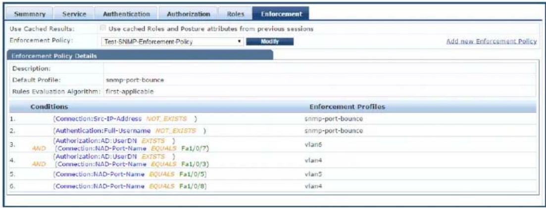
From the Services > Add > Enforcement page, you can either select an existing enforcement policy or create a new one.
- From the Enforcement Policy drop-down list, select the appropriate OnConnect Enforcement policy.
a. If you have not configured an OnConnect-type Enforcement policy, click Add New Enforcement Policy to create a new enforcement policy.
- Specify the values for the remaining parameters as described in Table 39, then click Save.
Table 39: Service Enforcement Page Parameters
| Parameter Description | |
| Use Cached Results | 1. Select this check box to use cached roles and posture attributes from previous sessions. |
| Enforcement Policy | 2. From the drop-down list, select the preconfigured enforcement policy. This is a mandatory step. |
| Enforcement Policy Details | |
| Description | Displays additional information about the selected enforcement policy. |
| Default Profile | Displays a default profile applied by . |
| Rules Evaluation Algorithm | Shows first matched rule and return the role or select all matched rules and return a set of roles. |
Event-Based Enforcement Service
The Event-Based Enforcement service manages enforcement actions in response to threat-event processing.
When there is a suspicious user, this user could represent a common DOS attack or some other threat. When a threat is detected, W-ClearPass performs enforcement operations as configured; for example, executing a change of authorization (COA) to disconnect a suspicious user from the network.
To add an event-based enforcement service:
- Navigate to Configuration > Services.
The Services page appears. The Services page provides options to add, modify, and remove a service.
- To add the service, click Add.
The Add Services dialog appears.
- From the Type drop-down list, select Event-based Enforcement (see Figure 65).
Figure 65: Specifying Event -Based Enforcement
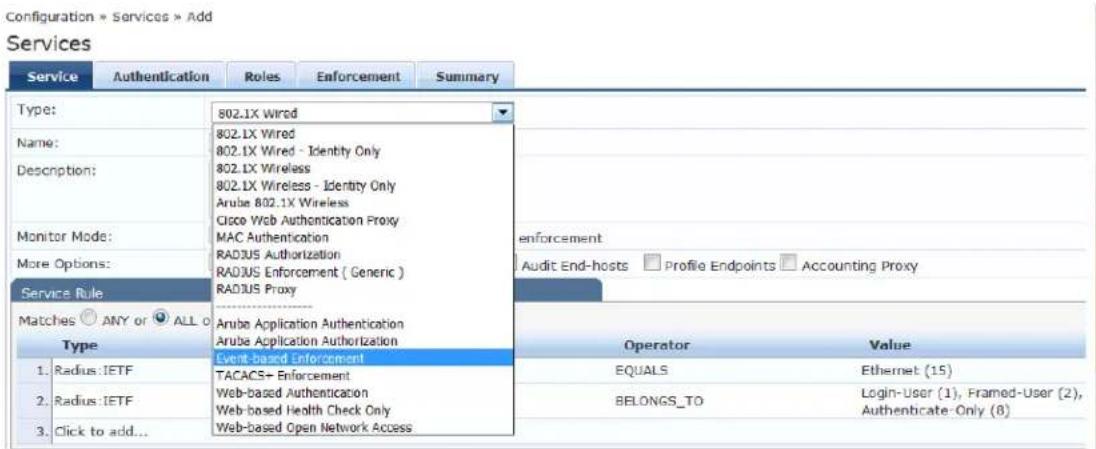
- Enter the name or label of the event-based enforcement service.
- Enter the values for any other parameters, including service rules, required for this service.
For a description of all the parameters in the Service page, see Adding Services on page 1.
Associating the Service with an Enforcement Policy
After you create the event-based enforcement service, you must associate the service with an enforcement policy. You can do this from the Services > Add > Enforcement page.
- When finished with the parameter settings on the Add Services > Service page, click Next.
The Services > Enforcement page appears.
Figure 66: Selecting the Ingress Events Enforcement Policy
![Configuration > Services > Add Services Service Enforcement Summary Use Cached Results: Use cached Roles and Posture attributes from previous sessions Enforcement Policy: Test-Event Enf-Policy Modify Add new Enforcement Policy Enforcement Policy Details Descriptions: Default Profile: [Anuba Terminate Session] Rules Evaluation Algorithm: first-applicable Conditions Enforcement Profiles 1. (Event:Juniper-SRX1:attack-name EXISTS) [Anuba Terminate Session], Update-Endpoint-Threat-Tags](/content/2026/05/842116/images/805e28f65fecb66608b06bb61ba9c65576d619fd87eb18f993033013cf4c1b74.jpg)
From the Services > Add > Enforcement page, you can either select an existing enforcement policy or create a new one.
- From the Enforcement Policy drop-down list, select the appropriate Event Enforcement policy.
- If you have not configured Event-type Enforcement policies, click Add New Enforcement Policy to create a new enforcement policy.
- Specify the values for the remaining parameters as described in Table 40, then click Save.
Table 40: Service Enforcement Page Parameters
| Parameter Description | |
| Use Cached Results 1. Select this check box to use cached roles and posture attributes from previous sessions. | |
| Enforcement Policy 2. From the drop-down list, select the preconfigured enforcement policy. This is mandatory. | |
| Enforcement Policy Details | |
| Description Displays additional | information about the selected enforcement policy. |
| Default Profile Displays a default profile applied by . | |
| Rules Evaluation Algorithm Shows first matched rule and return the role or select all matched rules and return a set of roles. | |
TACACS+ Enforcement Service
- Introduction
- Configuring a TACACS+ Multi-Factor Authentication Service
Introduction
Configure the TACACS+ Enforcement service for any kind of TACACS+ request.
TACACS+ users can be authenticated against any of the supported authentication source types:
- Local DB
SQL DB
• Active Directory - LDAP Directory
• Token Servers with a RADIUS interface
Similarly, you can specify service-level authorization sources from the Authorization tab.
You can associate a role-mapping policy with this service via the Roles tab.
The result of evaluating a TACACS+ enforcement policy is one or more TACACS+ enforcement profiles. For more information on TACACS+ enforcement profiles, see TACACS+ Based Enforcement Profile on page 419.
Creating a TACACS+ Enforcement Service
To create a TACACS+ Enforcement service:
- Navigate to Configuration > Services, then select the Add link.
The TACACS+ Enforcement service configuration dialog opens:
Figure 67: Adding a New TACACS+ Enforcement Service
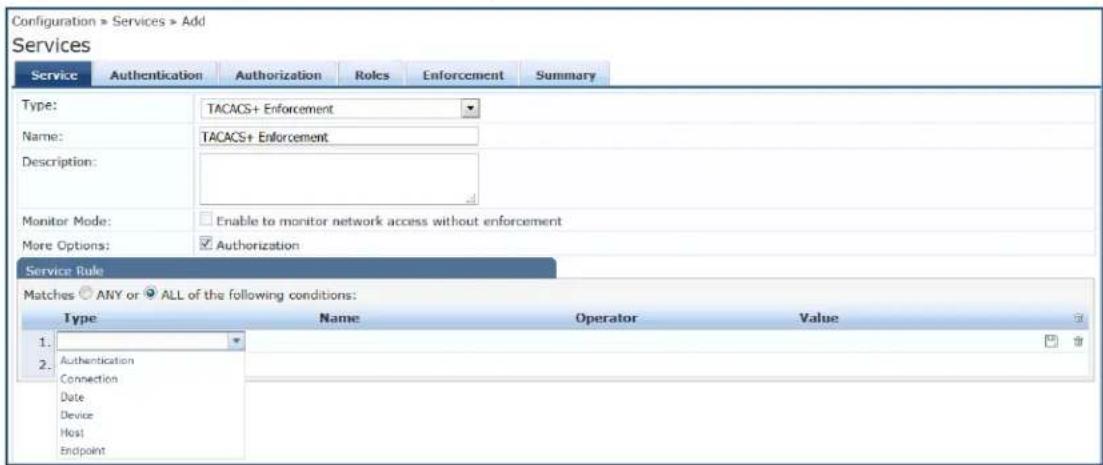
- Specify the Service tab parameters as described in the following table:
Table 41: Add TACACS+ Enforcement > Service Tab Parameters
| Parameter Action/Description | |
| Type From the drop-down | list, selectTACACS+ Enforcement. |
| Name Enter the name of the service. | |
| Description Provide additional information that helps to identify the service. | |
| Monitor Mode | TheMonitor Modeoption is disabled for an enforcement policy. |
| More Options TheAuthorizationtab is not enabled by default.To bring up theAuthorizationconfiguration tab, check theAuthorizationcheck box. | |
| Service Rule | |
| Type Select one of the following service rule types:AuthenticationConnectionDateDeviceHostEndpoint | |
| Name Select the name of | the service rule from the drop-down list. |
| Operator Select an appropriate operator from the list of operators for the data type of the attribute.For example, you can select from BELONGS_TO, NOT_BELONGS_TO, CONTAINS, EQUALS. | |
| Value Select the value from | the drop-down list. The value list depends on the operator selected. |
Configuring a TACACS+ Multi-Factor Authentication Service
W-ClearPass provides a way to differentiate between a TACACS+ login authentication and a TACACS+ enal authentication.
To do so, in Service and Policy rule configuration, you can use the Authentication type TacacsAuthenService parameter. This parameter accepts three values: None, Login, or Enable.
Note that an Enforcement policy can also use the Authentication: TacacsAuthenService attribute in the Rules Editor > Conditions section of the policy configuration.
Creating a TACACS+ Multi-Factor Authentication Service
To apply the TacacsAuthenService parameter in a TACACS+ Enforcement service:
- Navigate to Configuration > Services, then select the Add link.
The TACACS+ Enforcement service configuration dialog opens:
Figure 68: Configuring a TACACS+ Multi-Factor Authentication Service
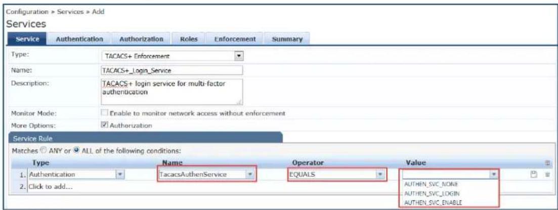
- Specify the TACACS+ Enforcement Service parameters as described in the following table:
Table 42: TACACS+ Enforcement > Service Tab Parameters
| Parameter Action/Description | |
| Type From the drop-down | list, select TACACS+ Enforcement. |
| Name Enter the name of the service. | |
| Description Provide additional information that helps to identify the service. | |
| Monitor Mode | The Monitor Mode option is disabled for an enforcement policy. |
| More Options The Authorization tab is not enabled by default.To bring up the Authorization configuration tab, check the Authorization check box. | |
| Service Rule | |
| Type | Select Click to add, then select the Authentication type. |
| Name Select TacacsAuthenService. | |
| Operator Select EQUALS. | |
| Value | Select one of the following values:AUTHEN_SVC_NONE: Choose this option when the user does not require authentication.AUTHEN_SVC_LOGIN: Choose this option when the user is authenticating in Login mode.AUTHEN_SVC_ENABLE: Choose this option when the user is authenticating in Privileged mode. |
Web-Based Authentication Service
This section provides the following information:
• About the Web-Based Authentication Service
• Selecting a Web-Based Authentication Service by the OS Name
• Service Rule > Web-Based Authentication Host Attributes
About the Web-Based Authentication Service
Configure a web-based authentication service for guests or agentless hosts that connect through the W-ClearPass Portal. The user is redirected to the W-ClearPass captive portal by the network device or by server that is set up to redirect traffic on a subnet to a specific URL.
The web page collects the user name and password, and also optionally collects health information on t following operating systems (see the Attribute Name OSType in Table 43 for details):
Linux
• Mac OS X
- Windows 10
- Windows 8
- Windows 7
- Windows Vista
- Windows XP
• Windows Server 2008
• Windows Server 2008 R2
• Windows Server 2003
• Windows Server 2003 R2
An internal service rule—Connection:Protocol EQUALS WebAuth—categorizes requests into this type of service. You can add additional rules if needed.
In addition, you can select a Web-based Authentication service based on the operating system (OS) name can specify or exclude specific OS versions (for details, see the next section, Selecting a Web-Based Authentication Service by the OS Name).
For service configuration details, see Adding and Removing Services on page 41.
To configure a web-based authentication service:
- Navigate to Configuration > Services.
The Services page opens.
- Select the Add link.
The Add Services page opens.
- From the Type drop-down list, select Web-Based Authentication.
The following service configuration dialog opens:
Figure 69: Web-Based Authentication Service Configuration Dialog
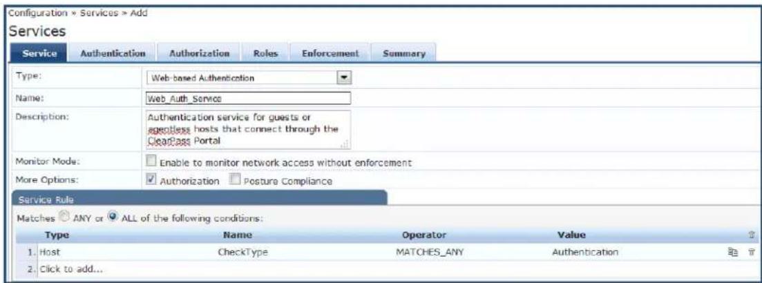

The Audit End-hosts and Profile Endpoints options are not available for a Web-based Authentication service.
Selecting a Web-Based Authentication Service by the OS Name
The Service Rule > Host:OSName attribute allows you to select a Web-based Authentication service based on the OS name. You can specify or exclude specific OS versions.
To select a web-based authentication service by the OS name and version:
1. From the Service tab > Service Rule area, select Click to add.
Figure 70: Host OS Name Specified in the Web-Based Authentication Service
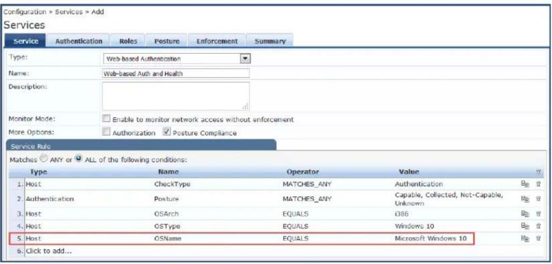
2. Specify the Host OS Architecture attribute as follows:
Type=Host
Name=OSArch
Operator=EQUALS
Value=i386 or x86_64
3. Specify the Host OS Type attribute as follows:
Type=Host
Name=OSType
Operator=EQUALS
Value=Windows 10
4. Specify the Host OS Name attribute as follows:
Type=Host
Name=OSName
Operator=EQUALS
■ Value=Microsoft Windows 10
Example Showing How to Differentiate Between Windows 8 and Windows 8.1
Type=Host
Name=OSName
Operator=CONTAINS
■ Value=Microsoft Windows 8.1
Service Rule > Web-Based Authentication Host Attributes
The following table describes the list of other attributes that can be used to create services based on the client's information.
Table 43: Service Rule > Web-Based Authentication Host Attributes
| Attribute Name | ||
| Host AgentType | Specifies the type of OnGuard Agent. This attribute provides a way to define a separate service for each OnGuard Agent Type. The supported values are:OnGuardAgent: OnGuard AgentOnGuardAgentService: OnGuard Agent running as a serviceNativeWebAgent: Native Dissolvable AgentJavaWebAgent: Java Dissolvable Agent | |
| Indicates the Fully Qualified Domain Name of the client. | ||
| to create services for a specific OS.For example, you can use this attribute to differentiate between Windows 8 and Windows 8.1 | ||
| OSNameVersion | Provides the Windows OS name and the build version. This attribute can be used to create different Posture policies for different Windows 10 versions such as2015 LTSB or 2016 LTSB. | |
| OSType | Specifies the Operating System type. The supported values are:LinuxMac OS XWindows XPWindows 7Windows 8Window 10Windows Server 2003Windows Server 2003 R2Windows Server 2008Windows Server 2008 R2 | |
| SDKType | Specifies the SDK type.For example, you can specify that the SDK type equals V4. For related information, see Upgrading From OnGuard Plugin Version 1.0 to 2.0 on page 740. | |
| SDKVersion | Specifies the SDK version. | |
| ServerCertificateCheck | This attribute's value shows the status of the W-ClearPass Server Certificate Check performed by OnGuard agent while sending a WebAuth request to the W-ClearPass server.This attribute can also be used in a Service Classification.The value of this attribute can be one of the following:Passed:OnGuard Agent successfully verified the W-ClearPass Server Certificate.Failured:OnGuard Agent failed to verify the W-ClearPass Server Certificate. | |
| UserAgent | The value of this attribute contains bothAgent Typeand Agent Version. For example, OnGuard 6.6.5.89660. | |
Web-based Health Check Only Service
This type of service is the same as the Web-based Authentication service except that there is no authentication performed; only health check are performed.
- The internal service rule Connection:Protocol EQUALS WebAuth categorizes requests into this type of service.
- The external service rule Host:CheckType EQUALS Health is automatically added when you select this type of service.
For more information, see Web-Based Authentication Service on page 107.
To create a Web-based Health Check Only service:
- Navigate to Configuration > Services, then select the Add link.
The Web-Based Health Check Only service configuration dialog opens:
Figure 71: Web-Based Health Check Only Service Configuration Dialog
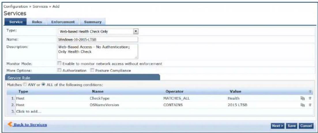
- Specify the Service tab parameters as described in the following table:
Table 44: Add Web-based Health Check Only Service > Service Tab Parameters
| Parameter Action/Description | |
| Type From the drop-down | list, selectWeb-based Health Check Only. |
| Name Enter the name of the service. | |
| Description Provide additional information that helps to identify the service. | |
| Monitor Mode Select the check box to monitor network access activity without enforcement. | |
| More Options | Check these boxes to access the additional configuration tabs:AuthorizationPosture Compliance |
| Service Rule | |
| Type | Select one of the following service rule types:AuthenticationConnectionDateDeviceHostEndpoint |
| Name Select the name of | the service rule from the drop-down list. |
| Operator Select an appropriate operator from the list of operators for the data type of the attribute.For example, you can select from BELONGS_TO, NOT_BELONGS_TO, CONTAINS, EQUALS. | |
| Value Select the value from | the drop-down list. The value list depends on the operator selected. |
Service Rule > Web-Based Authentication Host Attributes
The following table describes the list of other attributes that can be used to create host services based client's information.
Table 45: Service Rule > Web-Based Health Check Only Host Attributes
| Attribute Name | ||
| Host AgentType | Specifies the type of OnGuard Agent. This attribute provides a way to define a separate service for each OnGuard Agent Type. The supported values are:OnGuardAgent: OnGuard AgentOnGuardAgentService: OnGuard Agent running as a serviceNativeWebAgent: Native Dissolvable AgentJavaWebAgent: Java Dissolvable Agent | |
| Installed SHAs | Specifies the SHAs installed on the client. | |
| InterfaceType | Specifies the type ofNetwork Interface. This attribute can be used to define different services based on Network Interface type. The supported values are:WiredWirelessVPN | |
| Name | This is the host name of the client (without the domain name). | |
| OSArch | Specifies whether the client is running a 32-bit or 64-bit OS. The supported values are:i386: 32-bit OSx86_64: 64-bit OS | |
| OSName | Indicates the full Operating System name. This attribute can be used to create services for a specific OS.For example, you can use this attribute to differentiate between Windows 8 and Windows 8.1 | |
| OSNameVersion | Provides the Windows OS name and the build version. This attribute can be used to create different Posture policies for different Windows 10 versions such as2015 LTSB or 2016 LTSB. | |
| OSType | Specifies the Operating System type. The supported values are:LinuxMac OS XWindows XPWindows 7Windows 8Window 10Windows Server 2003Windows Server 2003 R2Windows Server 2008Windows Server 2008 R2 | |
| SDKType | Specifies the SDK type.For example, you can specify that the SDK type equalsV4. For related information, seeUpgrading From OnGuard Plugin Version 1.0 to 2.0 on page 740. | |
| SDKVersion | Specifies the SDK version. | |
| ServerCertificateCheck | This attribute's value shows the status of the W-ClearPass Server Certificate Check performed by OnGuard agent while sending a WebAuth request to the W-ClearPass server.This attribute can also be used in a Service Classification.The value of this attribute can be one of the following:Passed:OnGuard Agent successfully verified the W-ClearPass Server Certificate.Failured:OnGuard Agent failed to verify the W-ClearPass Server Certificate. | |
| UserAgent | The value of this attribute contains both the Agent Type and Agent Version.For example, OnGuard 6.6.7.89660. | |
Web-Based Open Network Access Service
Configuration for this service is the same as Web-based Authentication service, except that a health check is not performed on the endpoints.
A Terms of Service page (as configured on the W-ClearPass Guest Portal page) is presented to the user. Network access is granted when you click Submit Action.
The Posture option is not available for the Web-Based Authentication service. For more information, see Web-Based Authentication Service on page 107.
The following figure displays the Web-based Open Network service page configuration dialog:
Figure 72: Web-based Open Network Access Service Configuration Dialog
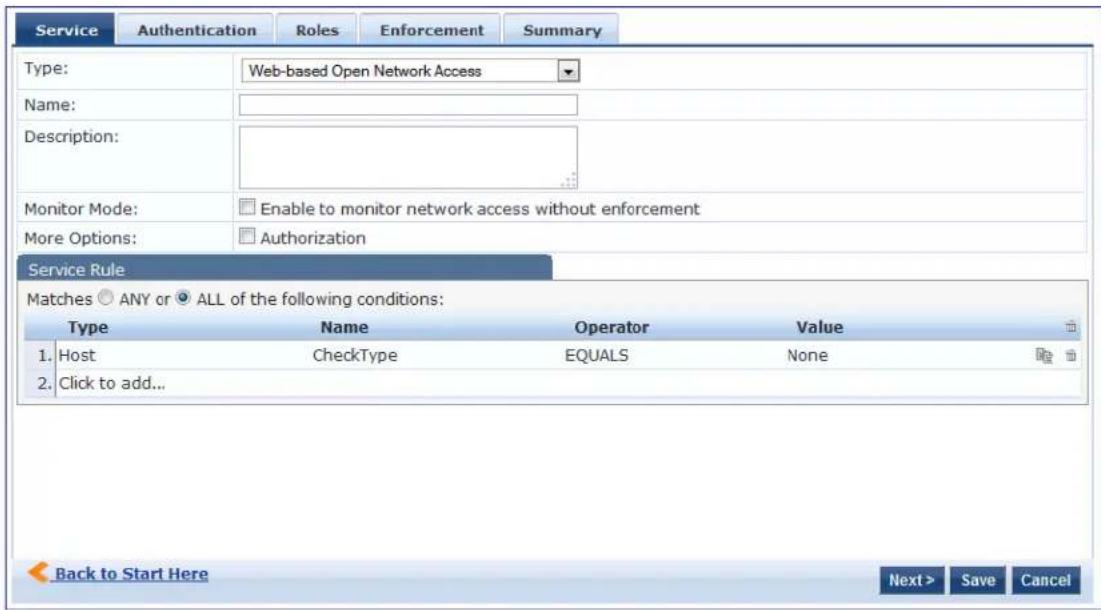
For configuration details, see Dell 802.1X Wireless Service on page 85.
The Monitoring features in Policy Manager provide access to live monitoring of components and other functions. W-ClearPass Policy Manager includes the following Monitoring features:
• Network Discovery
■ Profiler and Discovery: Network Discovery on page 153
• Live Monitoring
■ Live Monitoring: Access Tracker on page 117
■ Live Monitoring: Accounting on page 129
■ Live Monitoring: Analysis and Trending on page 146
■ Live Monitoring: OnGuard Activity on page 140
■ Live Monitoring: System Monitor on page 147
- Audit Viewer
■ Audit Viewer on page 167
• Event Viewer
■ Event Viewer on page 169
- Data Filters
■ Data Filters on page 172
- Blacklisted Users
■ Restoring Blacklisted Users to the Network on page 177
Live Monitoring: Access Tracker
This section provides the following information:
• About the Access Tracker
- Customizing the Access Tracker
• Viewing Access Tracker Session Details
About the Access Tracker
The Access Tracker provides a real-time display of per-session access activity on the selected server or domain.
- To view this page, navigate to Monitoring > Live Monitoring > Access Tracker. The Access Tracker page opens.
Figure 73: Access Tracker Page
![Monitoring > Live Monitoring > Access Tracker Access Tracker Dec 06, 2014 19:10:53 IST [All Requests] Garuda-197 ( ) Last 1 day before Today Edit Filter: Alerts contains Go Clear Filter Show 100 records Server Source Username Service Login Status Request Timestamp 1. 2014/05/27 WEBAUTH 00ff538baadf Health Only ACCEPT 2014/12/05 19:45:44 Showing 1-1 of 1](/content/2026/05/842116/images/b6ef2e16110bc10c8d018f2247032053cc3253e0830a57a708f265c42b39c1f2.jpg)
Table 46 describes the information in the Access Tracker page:
Table 46: Access Tracker Page Columns
| Column Description | |
| Server Displays the IP address of the server. | |
| Source Displays the authentication source for the session. For example, TACACS or web authentication (WEBAUTH). | |
| Username Displays the username or MAC address of the host. | |
| Service Displays the name of the service. | |
| Login Status | Displays the status of the request, such as Accept, Reject, or Timeout. |
| Enforcement Profiles | Displays the names of the enforcement profiles associated with the Service. |
| Request Timestamp | Displays the date and time when the status was last updated. |
Customizing the Access Tracker
To customize the Access Tracker parameters:
- From the Access Tracker page, click the Edit button (in the upper-right corner of the page).
The Edit Access Tracker page opens.
Figure 74: Edit Access Tracker Page
![Monitoring > Live Monitoring > Access Tracker Access Tracker Apr 10, 2017 20:32:00 UTC Auto Refresh Select Server/Domain: Select Filter: Select Date Range: 665_PTU_HYPV (10...) [All Requests] Last 1 day before Add Show Latest Select Columns: Available Columns Auth Type Host MAC Address NAS JP Address Monitor Mode Enforcement Profiles NAS Port Selected Columns Server Source Username Service Login Status Request Timestamp Up Down Modify Data Filter Save Cancel Filter: Request ID contains Go Clear Filter Show 10 records Server Source Username Service Login Status Request Timestamp](/content/2026/05/842116/images/aedd67f81ba0a7fccb0909d4638cde38385948069bf614ac3c7d7c6d0bb50c1a.jpg)
- Modify the Edit Access Tracker page parameters as described in the following table, then click Save:
Table 47: Edit Access Tracker Page Parameters
| Parameter Action/Description | |
| Select Server/Domain | Displays information for the selected server or domain on the Access Tracker page.To display transactions from all nodes in the Policy Manager cluster, select all the ser |
| Select Filter Select | a filter category to filter the displayed data.For a description of available filters, see Data Filters on page 172. |
| Modify Filter | To modify the current data filter, click the icon.For more information, see Data Filters on page 172. |
| Add Filter | To add a data filter, click the icon.The Data Filters page opens.For more information, see Data Filters on page 172. |
| Select Date Range | To select the start of the range of dates for which the Access Tracker table displays data, click the Last drop-down list.Available options are one to six days, or one week. |
| Select Date | To select a date, click the icon. |
| Show Latest | To set the date in the before field to the current date, click Show Latest. |
| Select Columns This section displays the following two fields:Available Columns: Displays the data column available to be displayed in an Access Tracker table.Selected Columns: Displays the data columns currently selected for display.To move a column name from one field to another:Select the column name and click the left or right arrows.To change the order in which the columns are displayed:Click a column name in the Selected Columns field, then click the Up or Down buttons. | |
Viewing Access Tracker Session Details
This section provides the following information:
• RADIUS Session
- WebAuth Session
• TACACS+ Session
RADIUS Session
This section provides the following information:
• RADIUS > Summary Tab
• RADIUS > Input Tab
• RADIUS > Output Tab
• RADIUS > Accounting Tab
To view details about a selected RADIUS session:
- Navigate to the Monitoring > Live Monitoring > Access Tracker page.
Figure 75: Access Tracker Page
![Monitoring > Live Monitoring > Access Tracker Access Tracker Feb 24, 2017 12:32:22 PST Auto Refresh [All Requests] qa199.amigopod.arubanetworks.com (10. Last 1 week before Today Edit Filter: Request ID contains Go Clear Filter Show 160 records Server Source Username Service Login Status Request Timestamp ? 1. 10. RADIUS 28:98:7b:01:21:fc Amigopod-MacAuth-Service ACCEPT 2017/02/24 04:18:48 2. 10. Application guest1@arubanetworks.com REJECT 2017/02/24 04:11:24 3. 10. Application admin [Guest Operator Logins] ACCEPT 2017/02/24 04:09:01 4. 10. WEBAUTH 28-98-7B-01-21-FC Amigopod-WebAuth-Service ACCEPT 2017/02/23 16:35:41 5. 10. RADIUS 28-98-7b:01:21:fc Amigopod-MacAuth-Service ACCEPT 2017/02/23 16:35:34 6. 10. WEBAUTH 28-98-7B-01-21-FC Amigopod-WebAuth-Service ACCEPT 2017/02/23 16:28:36 7. 10. WEBAUTH 28-98-7B-01-21-FC Amigopod-WebAuth-Service ACCEPT 2017/02/23 16:21:29 8. 10. WEBAUTH 28-98-7B-01-21-FC Amigopod-WebAuth-Service ACCEPT 2017/02/23 16:10:03](/content/2026/05/842116/images/7254c3a3b66a645d26eb56f8cbd05a7d8a94a0d32eb72d01c8236e6fbfc3dbb2.jpg)
- Click a RADIUS session in the Access Tracker table.
The Session Details for the selected RADIUS transaction are displayed. The information in this page varies depending upon the session selected.
RADIUS > Summary Tab
The Summary page shows the basic high-level information of the transaction.
Figure 76: Access Tracker > RADIUS Request Details > Summary Page
![Request Details Summary Input Output Accounting Login Status: ACCEPT Session Identifier: R00000059-01-58b024a8 Date and Time: Feb 24, 2017 04:18:48 PST End-Host Identifier: 28987b0121fc Username: 28:98:7b:01:21:fc Access Device IP/Port: 10. :0 (AutomationServer / Aruba) System Posture Status: UNKNOWN (100) Policies Used - Service: Amigopod-MacAuth-Service Authentication Method: MAC-AUTH Authentication Source: Local:localhost Authorization Source: [Endpoints Repository] Roles: [User Authenticated] Enforcement Profiles: [Allow Access Profile] Service Monitor Mode: Disabled Online Status: Offline Showing 1 of 1-100 records Change Status Show Configuration Export Show Logs Close](/content/2026/05/842116/images/e759d8a931831dc4653cb6ac9969da4baeb78e21beba3ca21353a572203d513c.jpg)
RADIUS > Input Tab
The Input tab shows protocol-specific attributes that Policy Manager received in a transaction request, including authentication and posture details (if available).
The Input tab also shows computed attributes that Policy Manager derived from the request attributes. All of these attributes can be used in role -mapping rules.
- To view the Input tab, click RADIUS session in the Access Tracker page, then select the Input tab. The Request Details > Input page opens.
Figure 77: Access Tracker > RADIUS Request Details > Input Page
![Request Details Summary Input Output Accounting Username: 28:98:7b:01:21:fc End-Host Identifier: 28987b0121fc Access Device IP/Port: 10. :0 (AutomationServer / Aruba) RADIUS Request Computed Attributes Authentication:ErrorCode 0 Authentication:Full-Username 28:98:7b:01:21:fc Authentication:Full-Username-Normalized 28:98:7b:01:21:fc Authentication:MacAuth KnownClient Authentication:OuterMethod MAC-AUTH Authentication:Posture Unknown Authentication:Source [Endpoints Repository] Authentication:Status MAB Authentication:Username 28:98:7b:01:21:fc Authorization:Sources [Endpoints Repository] Showing 1 of 1-100 records Change Status Show Configuration Export Show Logs Close](/content/2026/05/842116/images/0553cca753057e3b2fae78a60521b0f84cfbc3a7d5f85f367287013fd590fc12.jpg)
RADIUS > Output Tab
The RADIUS Request Details > Output tab shows the attributes that were sent to the network device (switch or controller) and the posture-capable endpoint (for example, MAC devices).
You can view the posture response and posture evaluation with accurate results. For example, you can \ details such as missing registry keys and the reasons for a failed registry key check.
To view the Request Details > Output page:
- Navigate to the Monitoring > Live Monitoring > Access Tracker page.
- Click any RADIUS session in the Access Tracker page.
- Select the Output tab.
The RADIUS Request Details > Output page opens:
Figure 78: Access Tracker > RADIUS Request Details > Output Page
![Request Details Summary Input Output Accounting Enforcement Profiles: [Allow Access Profile] System Posture Status: UNKNOWN (100) Audit Posture Status: UNKNOWN (100) Showing 1 of 1-100 records Change Status Show Configuration Export Show Logs Close](/content/2026/05/842116/images/fe387381dc8b7d9357cffb3b296fd0eed166384973653883bcd11fa242233838.jpg)

Access Tracker shows an alert if more than two anti-malware products are installed on a client.
RADIUS > Accounting Tab
The RADIUS Request Details > Accounting tab shows the account session details, as well as the following information:
• Network Details
• Utilization information
• Authentication Session Details
To view the RADIUS Request Details > Accounting page:
- Navigate to the Monitoring > Live Monitoring > Access Tracker page.
- Click any RADIUS session in the Access Tracker page.
- Select the Accounting tab.
The Request Details > Accounting page opens:
Figure 79: Access Tracker > RADIUS Request Details > Accounting Tab
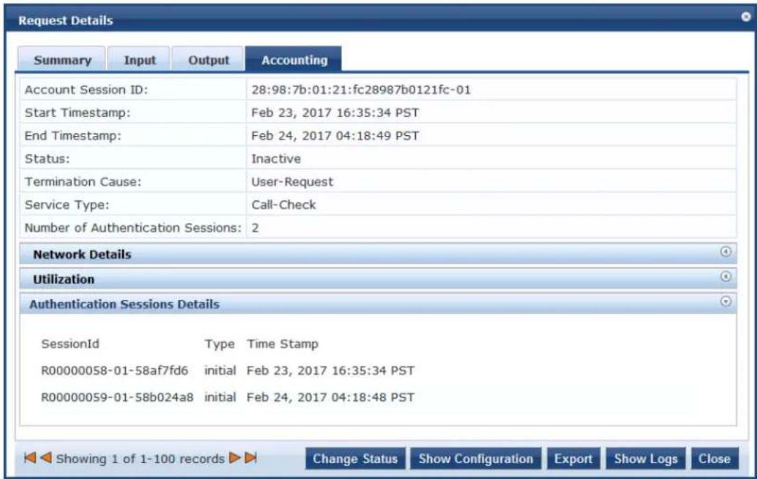
WebAuth Session
WebAuth (Web Authentication) is a single sign-on (SSO) authentication system for web pages and web applications. The first time a user attempts to access a web page protected by WebAuth, they are sent central login server and prompted to authenticate. Users are typically asked for a username and password although other authentication methods are possible.
Once the user has logged in, the weblogin server sends their encrypted identity back to the original web they were trying to access. Their identity is also stored in a cookie set by the weblogin server and they need to authenticate again until their credentials expire, even if they visit multiple protected web sites.
To view details about a selected WebAuth session:
- Navigate to the Monitoring > Live Monitoring > Access Tracker page.
The Access Tracker page opens. - Click a WebAuth session in the Access Tracker table.
WebAuth > Summary Tab
The Request Details page for the selected WebAuth (Web Authentication) transaction opens to the Summary page. The information in this page varies, depending upon the type of session selected.
Figure 80: Access Tracker > WebAuth Request Details > Summary Page
![Request Details Summary Input Output Login Status: ACCEPT Session Identifier: W0000000c-01-58af7fdc Date and Time: Feb 23, 2017 16:35:41 PST End-Host Identifier: 28987b0121fc Username: 28-98-7B-01-21-FC Access Device IP/Port: - System Posture Status: UNKNOWN (100) Policies Used - Service: Amigopod-WebAuth-Service Authentication Method: Not applicable Authentication Source: [Guest Device Repository] Authorization Source: [Guest Device Repository] Roles: [Employee], [User Authenticated] Enforcement Profiles: [Update Endpoint Known] Service Monitor Mode: Disabled Online Status: Offline Showing 4 of 1-100 records Change Status Show Configuration Export Show Logs Close](/content/2026/05/842116/images/3e557d8ca37a57e75c963cee02599c3ec7e9258b8475edd125075ab376a37d20.jpg)
The WebAuth Request Details > Summary page displays the basic WebAuth session information (login status, date and time, end-host identifier, and so on), as well as providing a section that summarizes the being applied and details about the policies and profiles in use.
WebAuth Input Tab
The Input tab shows protocol-specific attributes that Policy Manager received in a transaction request, including authentication and posture details (if available).
The Input tab also shows computed attributes that Policy Manager derived from the request attributes. All of these attributes can be used in role -mapping rules.
- To view the Input tab, click a WebAuth session in the Access Tracker page, then select the Input tab. The WebAuth Request Details > Input page opens.
Figure 81: Access Tracker > WebAuth Request Details > Input Page
![Request Details Summary Input Output Username: 28-98-7B-01-21-FC End-Host Identifier: 28987b0121fc Access Device IP/Port: - Computed Attributes Authentication:Full-Username 28-98-7B-01-21-FC Authentication:Full-Username-Normalized 28-98-7B-01-21-FC Authentication:Posture Unknown Authentication:Source [Guest Device Repository] Authentication:Status User Authentication:Username 28-98-7B-01-21-FC Authorization:Sources [Guest Device Repository] Connection:Client-Mac-Address 28987b0121fc Connection:Client-Mac-Address-Colon 28:98:7b:01:21:fc Connection:Client-Mac-Address-Dot 2898.7b01.21fc Connection:Client-Mac-Address-Hyphen 28-98-7b-01-21-fc Showing 4 of 1-100 records Change Status Show Configuration Export Show Logs Close](/content/2026/05/842116/images/b05cf3b10927906a519cc21e9fb4ef6f20a57f779b97f1936868312496dca61e.jpg)
WebAuth > Output Tab
The WebAuth Request Details > Output tab shows the attributes that were sent to the network device (switch or controller) and the posture-capable endpoint (for example, MAC devices).
You can view the posture response and posture evaluation with accurate results. For example, you can detail details such as missing registry keys and the reasons for a failed registry key check. The Output page also provides the RADIUS response summary.
To view the WebAuth Request Details > Output page:
- Navigate to the Monitoring > Live Monitoring > Access Tracker page.
- Click any WebAuth session in the Access Tracker page.
- Select the Output tab.
The WebAuth Request Details > Output page opens:
Figure 82: Access Tracker > WebAuth Request Details > Output Page
![Request Details Summary Input Output Enforcement Profiles: [Update Endpoint Known] System Posture Status: UNKNOWN (100) Audit Posture Status: UNKNOWN (100) RADIUS Response Status-Update:Endpoint Known Showing 4 of 1-100 records Change Status Show Configuration Export Show Logs Close](/content/2026/05/842116/images/617304758b4a3a72513a9e29a434d2da1b9887ee9f2a97ef605fe61149c0e30c.jpg)
TACACS+ Session
TACACS+ is a security application that provides centralized validation of users attempting to gain access to router or network access server. The goal of TACACS+ is to provide a methodology for managing multipl network access points from a single management service.
TACACS+ services are maintained in a database on a TACACS+ daemon running, typically, on a UNIX or Windows NT workstation. You must have access to and must configure a TACACS+ server before the configured TACACS+ features on your network access server are available.
To view details about a selected TACACS+ session:
- Navigate to the Monitoring > Live Monitoring > Access Tracker page.
The Access Tracker page opens.
Figure 83: Access Tracker Page with TACACS+ Session
![Monitoring » Live Monitoring » Access Tracker Access Tracker Feb 23, 2017 14:19:53 PST [All Requests] Clearpass.example.com (10...) Last 1 day before Today Filter: Request ID contains Go Clear Filter Show 10 records Server Source Username Service Login Status Request Timestamp 1. 10. TACACS admin [Policy Manager Admin Network Login Service] ACCEPT 2017/02/23 14:15:32 Showing 1-1 of 1](/content/2026/05/842116/images/b4693672a5c1548115426403eec45b27dbc31a5dde46e501b433962992f3a2ef.jpg)
- Click a TACACS+ session in the Access Tracker table.
TACACS+ > Summary Tab
The Session Details for the selected TACACS+ transaction opens to the Summary page.
Figure 84: Access Tracker > TACACS Session Details > Summary Page
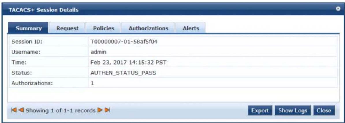
Table 48 describes the parameters in the TACACS+ Session Details Summary page.
Table 48: TACACS Session Details > Summary Page Parameters
| Field Action/Description | |
| Session ID Displays | the automatically-generated session ID for the selected TACACS+ session. |
| Username Indicates | the name of the admin user. |
| Time Indicates the time that the TACACAS+ session was initiated. | |
| Status Indicates the authentication status of the selected TACACS+ session. | |
| Authorizations Indicates the number of authentication authorizations that have taken place for this session. | |
| Export | To export the TACACS+ summary information, click Export. For details, see Importing and Exporting Information on page 32. |
| Show Logs | When you click Show Logs, the Request log details for session:are displayed. |
TACACS+ > Request Tab
The TACACS+ Request page provides the essential information regarding the TACACS+ authentication request.
Figure 85: Access Tracker > TACACS Session Details > Request Page
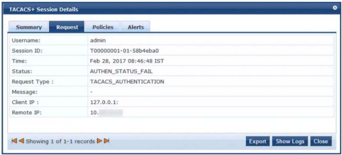
Table 49 describes the parameters in the TACACS+ Session Details Request page.
Table 49: TACACS Session Details > Request Page Parameters
| Field Action/Description | |
| Username Indicates | the name of the admin user. |
| Session ID Displays | the automatically-generated session ID for the selected TACACS+ session. |
| Time Indicates the time that the TACACS+ session was initiated. | |
| Status Indicates the authorization status of the selected TACACS+ session. The possible values are:AUTHEN_STATUS_PASSAUTHEN_STATUS_FAILAUTHEN_STATUS_GETDATAAUTHEN_STATUS_GETUSERAUTHEN_STATUS_GETPASSAUTHEN_STATUS_RESTARTAUTHEN_STATUS_ERRORAUTHEN_STATUS_FOLLOW | |
| Request Type Indicates the type of authentication request. There are three supported request types:TACACS AuthenticationTACACS AuthorizationTACACS Accounting | |
| Message | This is a message to be displayed to the user. |
| Client IP | This is the IP address of the device (for example, the ArubaOS switch)the remote IP device is attempting to log into. |
| Remote IP | This is the source IP address of the user device (for example, a laptop) attempting to log into the client device. |
TACACS+ > Policies Tab
The TACACS+ > Policies page provides the details regarding the Policy Manager role mapping policies used, authentication sources, and enforcement policies used (if available).
Figure 86: Access Tracker > TACACS Session Details > Policies Page
![TACACS+ Session Details Summary Request Policies Alerts Policies Used - Service Name : [Policy Manager Admin Network Login Service] Authentication Source : - Role: - Profiles: - Showing 1 of 1-1 records Export Show Logs Close](/content/2026/05/842116/images/da01b7282f9ca82f0e9f6668ea31206225354f857a75f7163015a4166c545990.jpg)
Table 50: TACACS Session Details > Policies Used Page Parameters
| Field Action/Description | |
| Service Name Indicates the name of the W-ClearPass service through which the user is authenticated. | |
| Authentication Source | Specifies the authentication source used bythe client. For more information, see Addi and Configuring Authentication Sources on page 207. |
| Role Indicates the Policy Manager role assigned to the client. For more information, see Adding and Modifying Roles on page 274. | |
| Profiles Indicates the Enforcement Profile configured for this service. For more information, see Configuring Enforcement Profile on page 373. | |
TACACS+ > Alerts Tab
The TACACS+ > Alerts page shows information about a session that has an error.
Figure 87: Access Tracker > TACACS+ Session Details > Alerts Page
. Failed to authenticate user=admin Showing 1 of 1-1 records Export Show Logs Close](/content/2026/05/842116/images/f2cebfd2a63cdc96e773fba6c91fd9472a77eb54ffe8541d0bea46b2e03b8959.jpg)
Table 51: TACACS Session Details > AlertsPage Parameters
| Field Action/Description | |
| Authentication Request Messages | |
| Error Category Indicates the error category. | |
| Error Code Dispays the error code. | |
| Alerts for This Request | |
| Alert source Indicates the source for this alert; in this case, the TACACS+ server. | |
| Alert message Displays the alert message. |
Live Monitoring: Accounting
This section provides the following information:
- Modifying the Accounting Page Parameters
• RADIUS Accounting Details > Summary Tab
• RADIUS Accounting Record Details > Auth Sessions Tab
• RADIUS Accounting Record Details > Utilization Tab
• RADIUS Accounting Record Details > Details Tab
• TACACS+ Accounting Record Details > Request Tab
• TACACS+ Accounting Record Details > Auth Sessions Tab
• TACACS+ Accounting Record Details > Details Tab
The Monitoring > Live Monitoring > Accounting page provides a dynamic report that describes session access, as reported by the network access device by means of RADIUS or TACACS+ accounting records.
The following figure displays the Live Monitoring > Accounting page:
Figure 88: Live Monitoring > Accounting Page
![Accounting [All Requests] nbalu-5175 (10.17.5.175) Last 1 day before Today Edit Filter: Protocol contains Go Clear Filter Show 10 records Server Protocol User Access Device Start Time 10.17.5.175 RADIUS nbalu-first 10.17.4.6:0 Jan 07, 2015 12:47:48 IST Showing 1-1 of more than 1 records](/content/2026/05/842116/images/551200107570ac591619e6fdf6915d52d27f6b2f5f19c918d7c4ab29e3cb6d7d.jpg)
The following table describes the Accounting parameters:
Table 52: Accounting Page Parameters
| Parameter Description | |
| Server | Specifies the IP address of the host name. |
| Protocol | Specifies the protocol used. |
| User | Displays the user name. |
| Access Device | Displays the IP address of the device. |
| Start Time | Displays the date and time. |
You can click any row in the Accounting page to drill down and display the corresponding Accounting Record Details page for the selected session. For details, see RADIUS Accounting Details > Summary Tab on page 131 and TACACS+ Accounting Record Details > Auth Sessions Tab on page 138.
Modifying the Accounting Page Parameters
You can filter or modify the information displayed in this table by creating a filter, or selecting a different server, domain, or time range.
To filter the data currently displayed in the Accounting page:
- Navigate to the Monitoring > Live Monitoring > Accounting page.
- Click Edit.

The Edit Accounting Page dialog opens.
Figure 89: Edit Accounting Page Dialog
![Accounting Select Server/Domain: .com.hz Select Filter: [All Requests] Select Date Range: Last 1 day before Show Latest Save Cancel Filter: Protocol contains Go Clear Filter Show 10 records Server Protocol User Access Device Start Time ? RADIUS nbalu-first Jan 07, 2015 12:47:48 IST Showing 1-1 of more than 1 records](/content/2026/05/842116/images/115faecedec9721810c416d669ac9c10f35f2d4e3967654e747d1eb43414bdb2.jpg)
3. Specify the Edit Accounting Page parameters as described in Table 53:
Table 53: Edit Accounting Page Parameters
| Parameter Action/Description | |
| Select Server/ Domain Select the W-ClearPass server for the dashboard data to be displayed. | |
| Select Filter To constrain the data display, select a filter from the drop-down list.You can select one of the following filters:ProtocolUserAccess Device | |
| Modify | To modify a data filter, click the Modify Data Filter icon (as shown in Figure 89). |
| Add | To create a new data filter, click the icon. |
| Select Date Range | Select the number of days prior to the configured date for which the accounting data to be displayed. You can specify the number from one day to a week. |
| Show Latest | To view the latest information, set the date to Today. |
| Select Columns | To move data between Available Columns and Selected Columns, click the right or left arrows.To rearrange columns, click the Up or Down buttons. |
RADIUS Accounting Details > Summary Tab
To drill down and display the corresponding Accounting Record Details page for the session, click any row in the Accounting page.
The Accounting Record Details > Summary tab shows a summary view of the transaction including session IDs, timestamp, and network details for the RADIUS protocol.
The following figure displays the RADIUS Accounting Record Details > Summary page:
Figure 90: RADIUS Accounting Record Details Summary Page
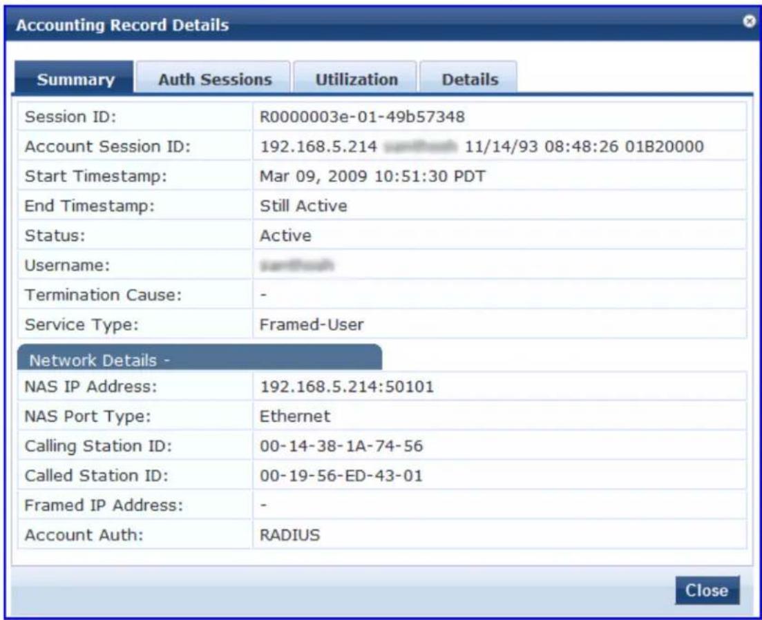
The following table describes the configuration parameters on the RADIUS Accounting Record Details > Summary page:
Table 54: RADIUS Accounting Record Details Summary Tab Parameters
| Parameter Description | |
| Session ID Specifies | the Policy Manager session identifier.You can correlate this record with a record in Access Tracker. |
| Account Session ID | Specifies a unique ID for this accounting record. |
| Start Timestamp End Timestamp | Shows the start time and end time of the session. |
| Status Shows the current connection status of the session. | |
| Username Username | associated with this record. |
| Termination Cause | Specifies the reason for termination of this session. |
| Service Type Shows | the value of the standard RADIUS attribute service type. |
| Network Details | |
| NAS IP Address Shows the IP address of the network device. | |
| NAS Port Type Shows the access methods. For example, Ethernet, or 802.11 Wireless. | |
| Calling Station ID Specifies the MAC address of the client that is supported by Policy Manager. | |
| Called Station ID Shows the MAC address of the network device. | |
| Framed IP Address Shows the IP address of the client (if available). | |
| Account Auth Specifies the type of authentication; for example, RADIUS authentication. | |
RADIUS Accounting Record Details > Auth Sessions Tab
This section describes the parameters of the Accounting Record Details > Auth Sessions tab for the RADIUS protocol.
The following figure displays the the Accounting Record Details > Auth Sessions page:
Figure 91: RADIUS Accounting Record Details > Auth Sessions Page
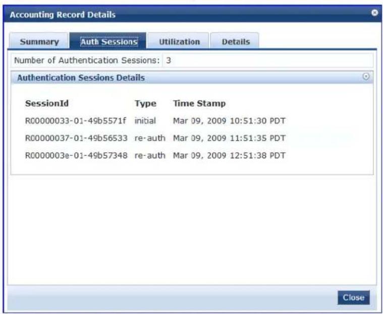
The following table describes the RADIUS Accounting Record Details >Auth Sessions parameters:
Table 55: RADIUS Accounting Record Details Auth Sessions Tab Parameters
| Parameter Description | |
| Number of Authentication Sessions | Specifies the total number of authentications (always 1) and authorizations in this session. |
| Authentication Sessions Details | |
| Session ID Displays the Policy Manager session ID. | |
| Type Specifies the type of authentication: Initial authentication or reauthentication. | |
| Time Stamp Specifies the time when the event occurred. | |
RADIUS Accounting Record Details > Utilization Tab
This section describes the parameters of the Accounting Record Details > Utilization tab for the RADIUS protocol.
The following figure displays the RADIUS Accounting Record Details > Utilization page:
Figure 92: RADIUS Accounting Record Details > Utilization Page
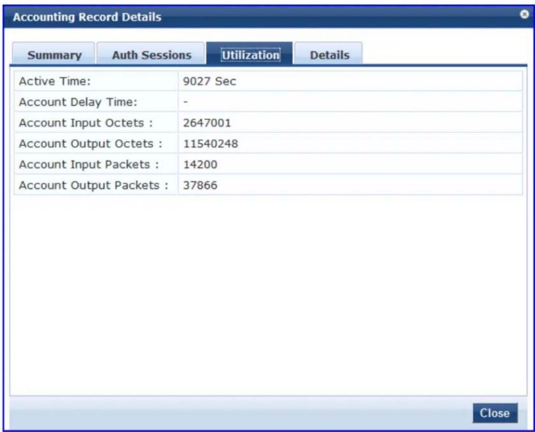
The following table describes the configuration parameters on the RADIUS Accounting Record Details - Utilization tab:
Table 56: RADIUS Accounting Record Details > Utilization Tab Parameters
| Parameter Description | |
| Active Time Displays the duration of the session that was active. | |
| Account Delay Time | Displays how many seconds the network device has been trying to send this record for (subtract from record time stamp to determine the time this record was actually genera the device). |
| Account Input Octets | Specifies the quantity of octets sent to and received from the device port during the se |
| Account Output Octets | |
| Account Input Packets | Specifies the packets sent and received from the device port during the session. |
| Account Output Packets | |
RADIUS Accounting Record Details > Details Tab
This section describes the parameters of the Accounting Record Details > Details tab for the RADIUS protocol.
The following figure displays the example of the RADIUS Accounting Record Details > Details page:
Figure 93: RADIUS Accounting > Details Page
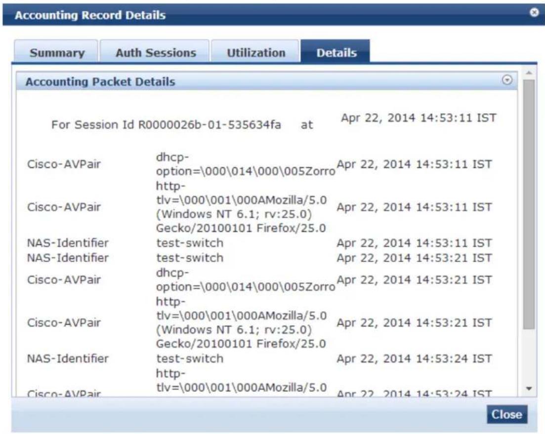
The following table summarizes the configuration information provided on the RADIUS Accounting Record Details > Details page:
Table 57: RADIUS Accounting Record > Details Page Summary
| Parameter Description | |
| Accounting Packet Details | Shows the details of RADIUS attributes sent and received from the network device dur initial authentication and subsequent reauthentications. Each section in the Details pag corresponds to a session in Policy Manager. |
TACACS+ Accounting Record Details > Request Tab
When you navigate to the Monitoring > Live Monitoring > Accounting page and select a TACACS+ Accounting record, the Accounting Record Details page opens to the Request page.
The following figure displays the TACACS+ Accounting Record Details > Request page:
Figure 94: TACACS+ Accounting Record Details > Request Page
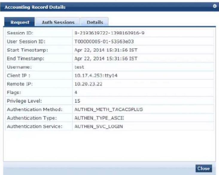
The following table describes the configuration parameters on the TACACS+ Accounting Record > Request page:
Table 58: TACACS+ Accounting Record Request Page Parameters
| Parameter Description | |
| Session ID | Specifies the Session ID, which is a unique ID associated with a request. |
| User Session ID Specifies a session ID that correlates authentication, authorization, and accounting records. | |
| Start and End Timestamp Shows | the start and end times of the session. |
| Username Shows the username associated with this record. | |
| Client IP Shows the IP address and tty (text terminal) of the device interface. | |
| Remote IP Shows the IP address | from which the Administrator is logged in. |
| Flags Shows the identifier corresponding to starting, stopping, or updating the accounting record. | |
| Privilege Level | Specifies the privilege level of the Administrator.The range is from 1 (lowest) to 15 (highest). |
| Authentication Method Identifies the authentication method used for network access. | |
| Authentication Type Identifies the authentication type used for network access. | |
| Authentication Service Identifies the authentication service used for network access. | |
TACACS+ Accounting Record Details > Auth Sessions Tab
This section describes the parameters of the Accounting Record Details > Auth Sessions tab for the TACACS+ protocol.
You can click any row in the Accounting page to display the corresponding Accounting Record Details page for the session.
- Navigate to the Monitoring > Live Monitoring > Accounting page.
- Select a TACACS+ Accounting record.
The Accounting Record Details page opens.
- To view the Authentication Sessions details, click the Auth Sessions tab.
The following figure displays the TACACS+ Accounting Record Details > Auth Sessions page:
Figure 95: TACACS+ Accounting Record Details > Auth Sessions Page
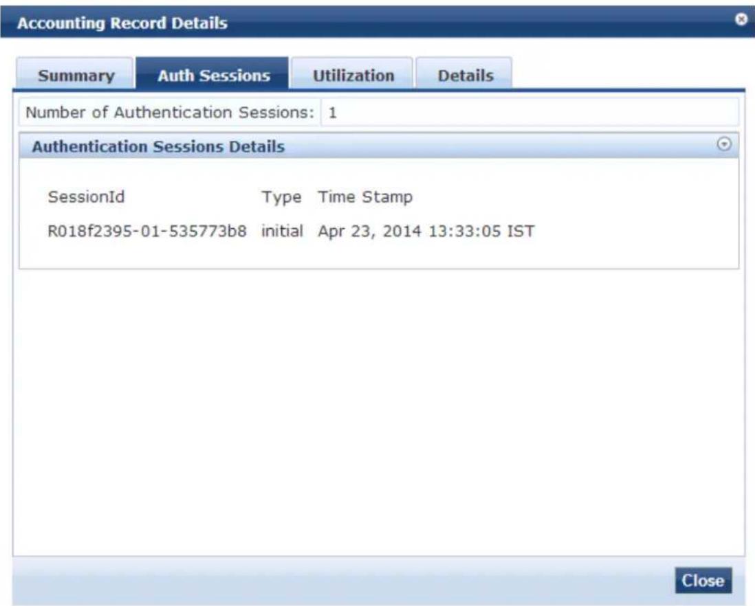
The following table summarizes the information available on the TACACS+ Accounting Record Details > Auth Sessions page:
Table 59: TACACS+ Accounting Record Details > Authentication Sessions Page Parameters
| Parameter Description | |
| Number of Authentication Sessions | Specifies the total number of authentications (always 1) and authorizations in this session. |
| Authentication Sessions Details | Denotes whether the request is an authentication or authorization request, and the time at which the request was sent for each request ID. |
TACACS+ Accounting Record Details > Details Tab
This section describes the parameters of the Accounting Record Details > Details page for the TACACS+ protocol.
You can click any row in the Accounting page to display the corresponding Accounting Record Details page for the session.
- Navigate to the Monitoring > Live Monitoring > Accounting page.
- Select a TACACS+ Accounting record.
The Accounting Record Details page opens.
- To view the sessions details, click the Details tab.
The following figure displays the TACACS+ Accounting Record Details > Details page:
Figure 96: TACACS+ Accounting Record Details > Details Page
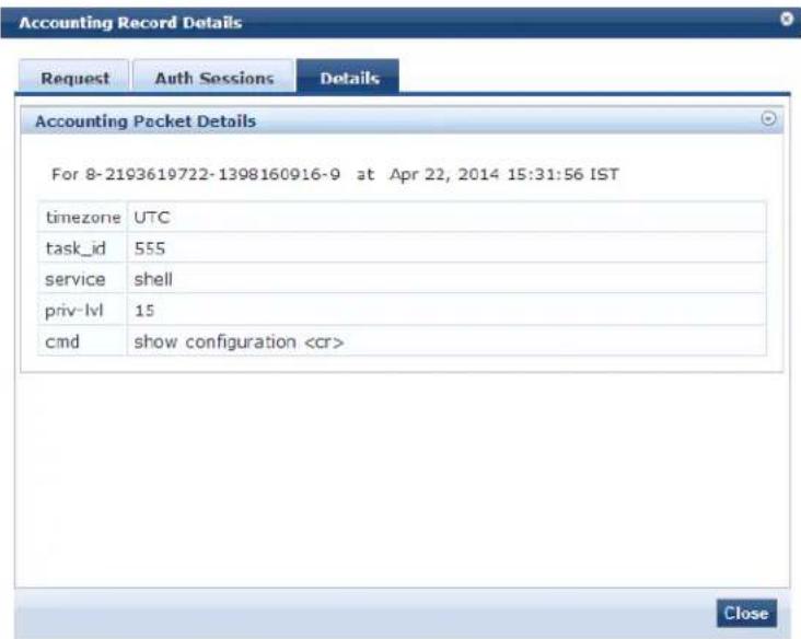
The following table summarizes the configuration parameters provided on the TACACS+ Accounting Record > Details tab:
Table 60: TACACS+ Accounting Record > Details Page Parameters
| Parameter | Description |
| Accounting Packet Details | Shows command typed (cmd), privilege level of the administrator executing the command (priv-lvl) and service (shell) for each authorization request, as well as the start time, task ID, and the time zone. |
Live Monitoring: OnGuard Activity
This section provides the following information:
• About OnGuard Activity
• Bouncing an Agent Using Non-SNMP
• Bouncing a Client Using SNMP
- Broadcasting a Message to Active Endpoints
- Sending a Message to Selected Endpoints
About OnGuard Activity
The OnGuard Activity page shows the real-time status of all endpoints that have W-ClearPass W-OnGuard persistent agent.
This page also presents configuration tools to bounce an endpoint and to send unicast or broadcast me: to all endpoints running the W-OnGuard agent.
To access the OnGuard Activity page:
- Navigate to Monitoring > Live Monitoring > OnGuard Activity.
The OnGuard Activity page opens:
Figure 97: OnGuard Activity Page
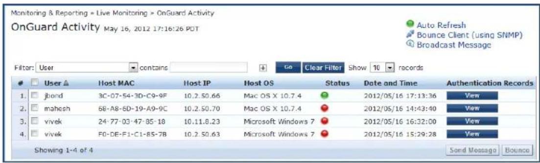
The following table describes the configuration parameters on the OnGuard Activity page:
Table 61: OnGuard Activity Parameters
| Parameter Description | |
| User Displays the name of the user. | |
| Host MAC Displays the MAC address of the host. | |
| Host IP Displays the IP address of the host. | |
| Host OS Displays the operating system that runs on the host. | |
| Status Displays the online status of the host. Green indicates online and red indicates offline. | |
| Date and Time Displays the date and time at which the user was created. | |
| Authentication Records | Click the Authentication Records > View button to see the Endpoint Authentication Details page with the authentication records. |
Bouncing an Agent Using Non-SNMP
This page is used to initiate a bounce on an endpoint's managed interface.
Endpoint bounce only works with endpoints that run the W-OnGuard persistent agent.
Initiating a bounce on the managed interface on the endpoint results in creating tags for the specified e in the Endpoints page (navigate to Configuration > Identity > Endpoints).
One or more of the following tags are created:
- Disabled by
- Disabled Reason
- Enabled by
- Enabled Reason
- Info URL
To bounce an agent:
- Navigate to Monitoring > OnGuard Activity.
The OnGuard Activity page opens. - Click a device listed on the OnGuard Activity page.
The Agent and Endpoint Details page opens.

Figure 98: Agent and Endpoint Details
![Agent and Endpoint details User: Host MAC: Host IP: Status: Agent Type: Host OS: Registered Policy Manager Server: Registered at: Last Unregistered at: Last Seen Health Status: Unhealthy Health Classes: a f0def133a1a3 10.20.23.125 Offline OnGuard Windows 7 HW-4.15-SFO-25K [10.17.4.15] 2014/03/04 14:33:59 2014/04/03 14:56:56 - - Description: Status: Added by: Unknown Policy Manager Send Message Bounce Close](/content/2026/05/842116/images/191a05e90de070feef88c9aa966981b69266bfb84ead6f8343221aa845db245e.jpg)
The following table describes the configuration parameters on the Agent and Endpoint Details page:
Table 62: Agent and Endpoint Details Parameters
| Parameter Description | |
| Host MAC Displays the MAC address of the user. | |
| Description Optional description of the endpoint. | |
| Status Displays the status of the endpoint. | |
| Added by Displays the server name. | |
| MAC Vendor Vendor name and OS of the endpoint device. | |
| OnGuard Details | |
| User | Displays the name of the user. |
| Host IP | Displays the IP address of the host. |
| Status Shows the online or offline status of the agent. | |
| Agent Type | Specifies the type of the OnGuard agent. |
| Host OS Displays the operating system that runs on the endpoint. | |
| Registered Policy Manager Server | Displays the name and IP address of the Policy Manager server. |
| Registered at Displays the date and time at which the Policy Manager installation was registered. | |
| Last Unregistered at Displays | the date and time at which the Policy Manager installation was last unregistered. |
| Last Seen Health Status Displays the health status of the endpoint. For example, QUARANTINED or HEALTHY. | |
| Unhealthy Health Classes Displays the health classes that are unhealthy. | |
3. Click Bounce.
The Bounce Agents page opens.
Figure 99: Bounce Agents Page
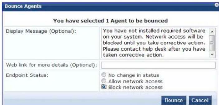
The following table describes the configuration parameters on the Bounce Agents page:
Table 63: Bounce Agents Page Parameters
| Parameter | Action/Description |
| Display Message (Optional) | An optional message to display on the endpoint using the OnGuard interface. |
| Web link for more details (Optional) | An optional clickable URL that is displayed along with the Display Message. |
| Endpoint Status | No change in status: No change is made to the status of the endpoint. The existing status of Known, Unknown, or Disabled continues to be applied. Access control is granted or denied based on the existing status of an endpoint. |
| Parameter Action/Description | |
| Allow network access: Allow network access by white-listing this endpoint. Clicking Allow network access sets the status of the endpoint as Known.NOTE: You must configure Enforcement Policy Rules to allow access to the endpo with the status Known.Block network access: Block network access by blacklisting this endpoint. Clicking Block network access sets the status of the endpoint to Disabled.NOTE: You must configure Enforcement Policy Rules to allow access to the endpoints with the status Disabled. |
Bouncing a Client Using SNMP
The Bounce Client (using SNMP) dialog is used to initiate a bounce operation using SNMP with wired Ethernet switches.
Endpoint bounce only works with endpoints that run the W-OnGuard persistent agent.
Requirements
To successfully bounce a client using SNMP, the following conditions are required:
- The network device must be added to Policy Manager and SNMP read and write parameters must be configured.
For information about adding a network device to W-ClearPass Policy Manager, see Adding a Network Device on page 464.
For details about configuring SNMP settings, see SNMP Read Settings Parameters on page 466 and SNMP Write Settings Parameters on page 468. - SNMP traps (link up and/or MAC notification) must be enabled on the switch port (see W-ClearPass SNMP Traps and OIDs on page 872 and SNMP Trap Details on page 874).
- The DHCP snooper service on a W-ClearPass server must receive DHCP packets from the endpoint to specify the IP address of the endpoint to bounce.
For information about configuring the DhcpSnooper service, see W-ClearPass Network Services Options on page 510.
■ For information about configuring the IP helper address, see DHCP Collector on page 453.
Bouncing a Client
To bounce a client using SNMP:
-
Navigate to Monitoring > OnGuard Activity. The OnGuard Activity page opens.
-
Click the Bounce Client (using SNMP) link on the top-right of the OnGuard Activity page. The Bounce Client (using SNMP) dialog opens.

Figure 100: Bounce Client (Using SNMP) Dialog
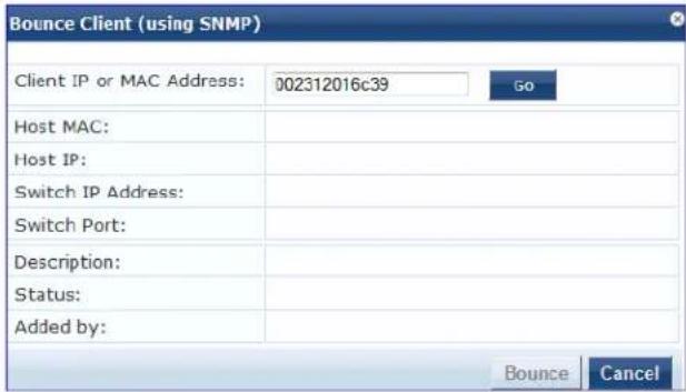
-
Enter the client IP or MAC Address.
-
Click Go, then click Bounce.
The following table describes the configuration parameters on the Bounce Client (Using SNMP) page:
Table 64: Bounce Client (Using SNMP) Page Parameters
| Parameter Action/Description | |
| Client IP or MAC address Enter the client IP address or MAC address of the bounce client. | |
| Host MAC Displays the MAC address of the host. | |
| Host IP Displays the IP address of the host. | |
| Switch IP Address Displays the IP address of the switch. | |
| Switch Port Displays the port number of the switch. | |
| Description Displays the description of the client. | |
| Status Displays the status of the client. | |
| Added by Displays the name of the user who added the client. |
Broadcasting a Message to Active Endpoints
To broadcast a message to selected active endpoints:
- Navigate to Monitoring > OnGuard Activity.
The OnGuard Activity page opens.
-
Select the endpoint(s) that you want to broadcast to.
-
Click the Broadcast Message link on the top-right of the OnGuard Activity page.
The Broadcast Notification to Agents dialog opens.
Figure 101: Broadcast Notification to Agents Dialog
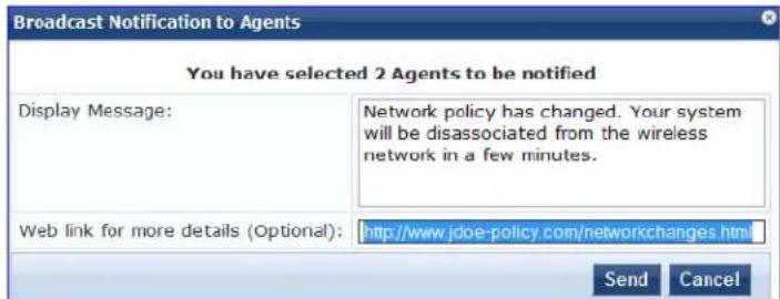
- Display Message: Enter the text of the message you want to send to the selected active endpoints.
- Web link: Optionally, enter a URL to be included with the Display Message.
- Click Send.
Sending a Message to Selected Endpoints
To send a message to selected endpoints:
- Navigate to Monitoring > OnGuard Activity.
The OnGuard Activity page opens. - Select one or more devices listed on the OnGuard Activity page.
- Click the Send Message button.
The Send Notification to Agents dialog opens.
Figure 102: Send Notifications to Agents
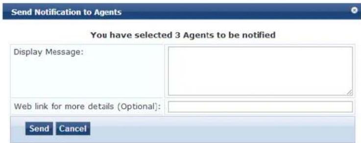
- Display Message: Enter a message to be sent to the selected endpoints
- Web link: Optionally, enter a URL to be included with the message.
- Click Send.
Live Monitoring: Analysis and Trending
The Analysis and Trending page displays requests for the subset of components included in the selected filters over a selected time period: one month, two weeks, one week, one day, 12 hours, 6 hours, 3 hours, one hour.
The data can be aggregated by minute, hour, day, or week. The list at the end of this section shows the per-filter count for the aggregated data.
Each bar corresponding to each filter in the bar graph is clickable. Clicking a bar drills down into the Ac Tracker (see Live Monitoring: Access Tracker on page 117) that shows session data for the specific time-slice and for the specific requests.
- To access this page, navigate to Monitoring > Live Monitoring > Analysis and Trending.
Figure 103: Analysis and Trending
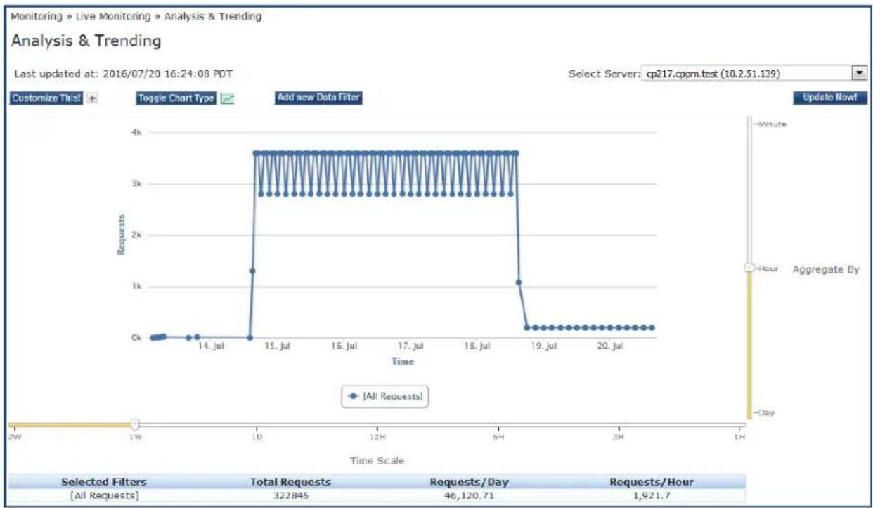
line
| Time Scale | Selected Filters | Total Requests | Requests/Day | Requests/Hour | | ---------- | ---------------- | -------------- | ------------ | ------------- | | 2W | - | - | - | - | | 1W | - | - | - | - | | 14 Jul | - | - | - | - | | 10 | - | - | - | - | | 15 Jul | - | - | 3500 | - | | 16 Jul | - | - | 3500 | - | | 17 Jul | - | - | 3500 | - | | 18 Jul | - | - | 3500 | - | | 6H | - | - | 3500 | - | | 19 Jul | - | - | 200 | - | | 20 Jul | - | - | 200 | 1,921.7 | | 1H | - | - | - | - |- Use the following components in the user interface to customize and filter the Analysis and Trending page:
| Component Action/Description | |
| Select Server Select a W-ClearPass node from the cluster. | |
| Update Now! Click to update the display with the latest available data. | |
| Customize This! Click to customize the display by adding filters. You can add a maximum of four filters. | |
| Toggle Chart Type Click to | toggle the chart display between line and bar type. |
| Add New Data Filter Click | to add a data filter in the global filter list.For more information on adding filters, refer to Data Filters on page 172. |
Live Monitoring: System Monitor
The System Monitor page has four tabs. Each tab provides one or more charts or graphs that give real-time information about various components.
Auto refresh ensures that the System Monitor page is updated for every two minutes. You can see the last updated time in the Last updated at field in the System Monitor page.

• System Monitor Page
- Process Monitor Page
• Network Monitor Page
• ClearPass Monitor Page
System Monitor Page
The System Monitor page displays charts and graphs that display information about CPU load, CPU usage, memory usage, and disk usage for the selected W-ClearPass server.
To access the System Monitor page for the selected W-ClearPass server:
- Navigate to Monitoring > Live Monitoring > System Monitor.
- From the Select Server drop-down, select the desired W-ClearPass server.
Figure 104: System Monitor Page
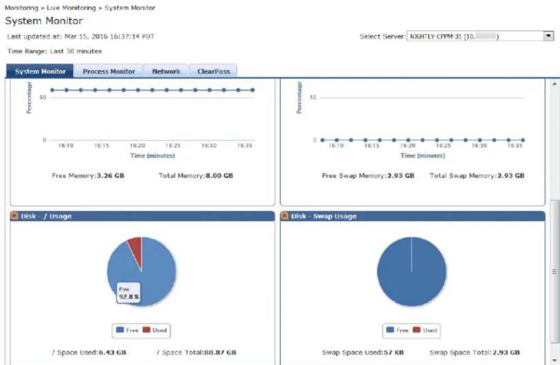
line
| Metric | Value | | :--- | :--- | | Free Memory (%) | 3.26 GB | | Total Memory (%) | 8.00 GB | | Free Swap Memory (%) | 2.93 GB | | Total Swap Memory (%) | 2.93 GB | | / Space Used (%) | 6.43 GB | | / Space Total (%) | 88.87 GB | | / Space Used / Used (%) | 92.8% | | / Space Used / Used (%) | 57 KB | | / Space Used / Used (%) | 2.93 GB |Table 65: System Monitor Page Report Widgets
| Widget Description | |
| CPU Usage | Percentage of CPU usage for the following: System, User, I/O Wait, and Idle time. |
| CPU Load | Percentage of CPU load averages in increments of 1, 5, and 15 minutes. |
| Memory Usage | Percentage of free and total memory in Gigabytes. |
| Swap Memory Usage | Percentage of free and total swap memory in Gigabytes. |
| Disk - Usage | Percentage of used and free disk space. |
| Disk - Swap Usage | Percentage of used and total swap space. |
Process Monitor Page
The Process Monitor page displays CPU Usage and Main Memory Usage for a selected process or service.
To access the Process Monitor page:
- Navigate to Monitoring > Live Monitoring > System Monitor > Process Monitor.
Figure 105: System Monitoring: Process Monitor Page
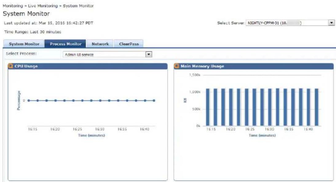
line
| Time (minutes) | CPU Usage (%) | | -------------- | ------------- | | 16:15 | 0 | | 16:20 | 0 | | 16:25 | 0 | | 16:30 | 0 | | 16:35 | 0 | | 16:40 | 0 |- To view CPU Usage and Main Memory usage for the selected process or service, click the Select Process drop-down list.
- Select one of the following options :
■ Admin UI service
■ AirGroup notification service
■ Apache web server
■ Async DB write service
■ Async network services
■ W-ClearPass IPsec service
■ DB change notification server
■ DB replication service
■ Domain service
■ Extensions service
■ Ingress logger service
■ Ingress logrepo service
■ Micros Fidelio FIAS
■ Multi-master cache
■ Policy server
- Radius server
■ Stats aggregation service
■ Stats collection service
■ System auxiliary services
■ System monitor service
Tacacs server
■ Virtual IP service
Network Monitor Page
The Network Monitor page displays information about the selected network traffic type.
To access the Network Monitor page:
- Navigate to Monitoring > Live Monitoring > System Monitor > Network tab.
- From the Select drop-down, select the desired traffic type.
Figure 106: Network Monitor Page
Monitoring » Live Monitoring » System Monitor
System Monitor
Last updated at: Mar 15, 2016 20:16:14 EDT
Time Range: Last 30 minutes

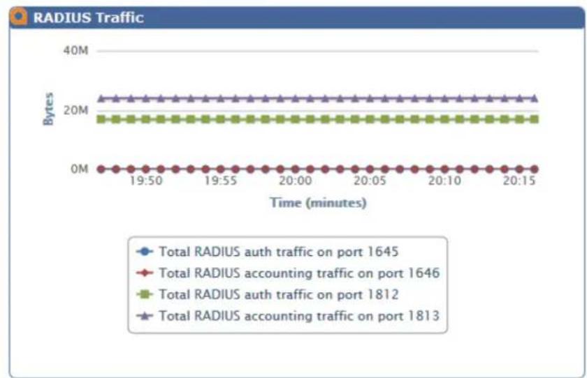
line
| Time (minutes) | Total RADIUS auth traffic on port 1645 | Total RADIUS accounting traffic on port 1646 | Total RADIUS auth traffic on port 1812 | Total RADIUS accounting traffic on port 1813 | | -------------- | -------------------------------------- | --------------------------------------------- | -------------------------------------- | --------------------------------------------- | | 19:50 | 0M | 0M | 20M | 20M | | 19:55 | 0M | 0M | 20M | 20M | | 20:00 | 0M | 0M | 20M | 20M | | 20:05 | 0M | 0M | 20M | 20M | | 20:10 | 0M | 0M | 20M | 20M | | 20:15 | 0M | 0M | 20M | 20M |The Network Monitor page displays network activity (in bytes) for the following traffic types:
- OnGuard
- Database
- Web Traffic
• RADIUS
TACACS
• SSH
NTP
ClearPass Monitor Page
The ClearPass Monitoring page displays performance monitoring counters and timers for the last 30 minutes of activity for the following W-ClearPass components:
• Service Categorization
• Authentication (RADIUS, TACACS, or WebAuth)
- Authorization
- Role Mapping
• Posture Evaluation
- Audit Scan
- Enforcement
• End-to-End Request Processing (RADIUS, TACACS, or WebAuth)
- Advanced
To access the ClearPass Monitor page:
- Navigate to Monitoring > Live Monitoring > System Monitor > ClearPass tab.
- Click the Select drop-down.
- Select the desired W-ClearPass performance monitoring counter.
Figure 107: System Monitoring: ClearPass Monitor Page

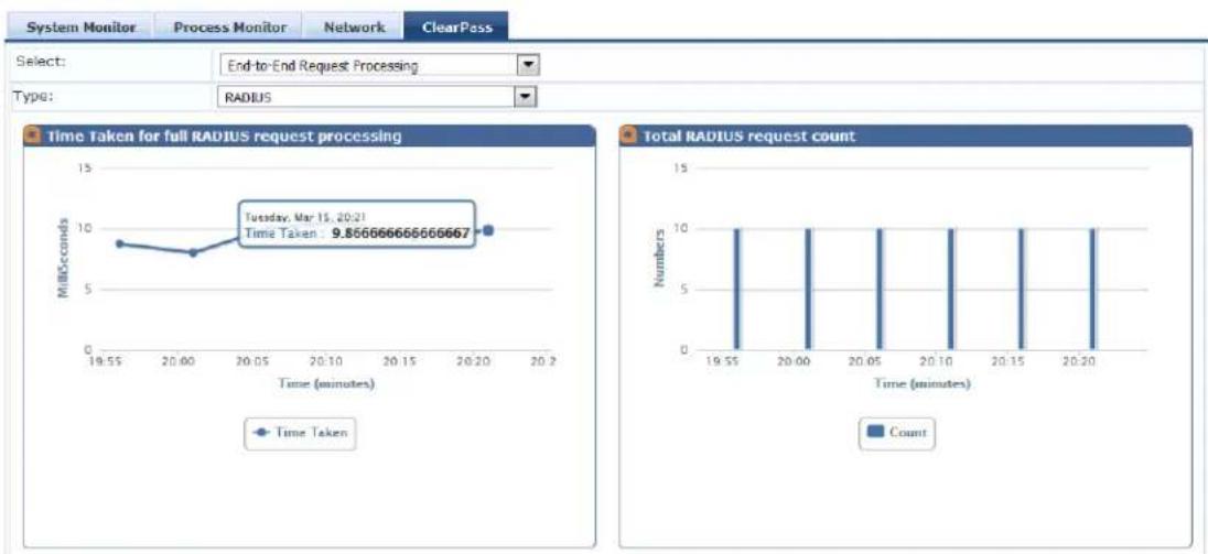
Profiler and Discovery
This section provides the following information:
• Profiler and Discovery: Endpoint Profiler
• Profiler and Discovery: Network Discovery
Profiler and Discovery: Endpoint Profiler
If the Profile license is enabled, a list of the profiled endpoints are visible in the Endpoints Profiler page.
- To access the Endpoint Profiler, navigate to the Monitoring > Profiler and Discovery > Endpoint Profiler page.
The list of endpoints you view is based on the Device Category, Device Family, and Device Name items that you selected.
Figure 108 shows an example of the graphs available on the Endpoint Profiler page:
Figure 108: Endpoint Profiler Page
Monitoring > Live Monitoring > Endpoint Profiler
Endpoint Profiler
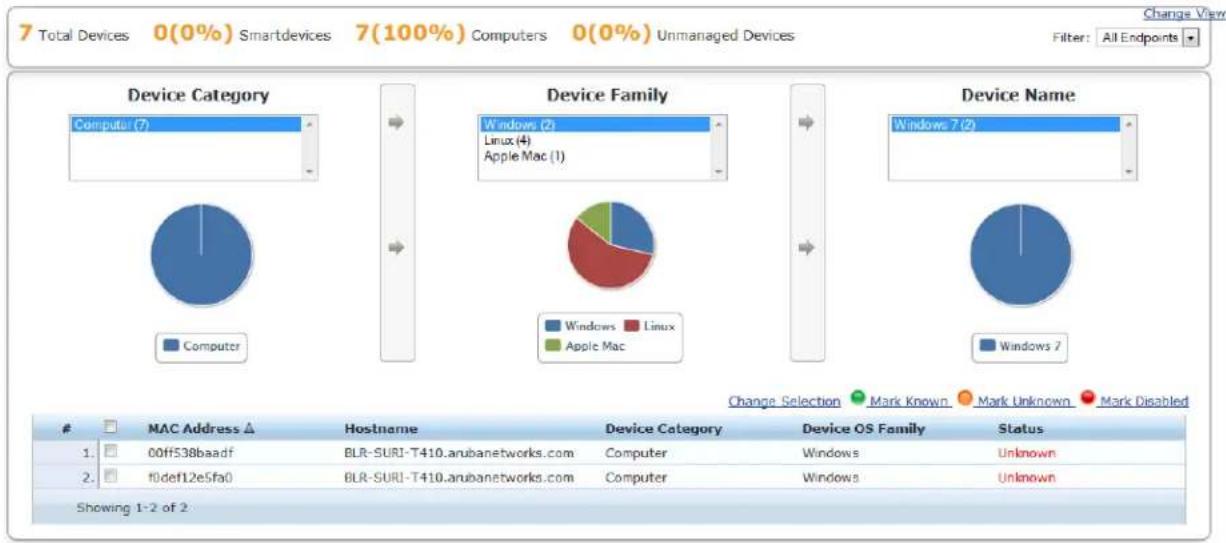
pie
| Device Category | Windows | Linux | Apple Mac | | :--- | :--- | :--- | :--- | | Computer | 7 | 0 | 0 | | Windows 2 | 2 | 4 | 1 | | Linux | 0 | 0 | 0 | | Apple Mac | 0 | 0 | 0 | | Device Name | Windows 7 | Windows 2 | Windows 7 | | :--- | :--- | :--- | :--- | | Change Selection | Mark Known | Mark Unknown | Mark Disabled | | # MAC Address △ Hostname Device Category Device OS Family Status 1. 00ff538baadf BLR-SURI-T410.arubanetworks.com Computer Windows Unknown 2. f0def12e5fa0 BLR-SURI-T410.arubanetworks.com Computer Windows Unknown Showing 1-2 of 2: Change View 7 Total Devices 0(0%) Smartdevices 7(100%) Computers 0(0%) Unmanaged Devices Filter: All Endpoints Change View- To modify the selection criteria used to list the devices, click Change Selection.
- To see graphs that show information about distribution and update frequency for devices and comput click Change View.
- To view endpoint details about a specific device, click a device in the table below the graphs. The Endpoint Profiler Details > Endpoint page opens:
Figure 109: Endpoint Profiler Details
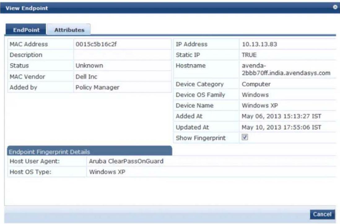
- To return to the Endpoint Profiler page, select the Cancel button.
Profiler and Discovery: Network Discovery
This section provides the following information:
• About Network Discovery
- Adding the Configurations to Query Seed Devices
• SNMP Credentials Configuration
• SSH Credentials Configuration
• SSH Credentials Configuration
• WMI Credentials Configuration
- Initiating a Network Discovery Scan
- About Auto-Refresh
- Importing and Viewing Discovered Network Devices
• Viewing Discovered Endpoints
- Configuring Nmap-Based Endpoint Port Scans
About Network Discovery
Network Discovery uses a configured seed network device (typically a switch, router, or controller) to discover endpoints and network devices.
The following information is read from the seed device:
• SNMP information
An SNMP description is necessary for discovering and profiling the network devices. For more information see SNMP Credentials Configuration on page 154.
- SSH credentials
For Linux server or network device discovery, specify SSH configuration credentials. For more information see SSH Credentials Configuration on page 156.
• WMI credentials
For Windows device discovery, specify WMI (Windows Management Instrumentation) credentials. For more information, see WMI Credentials Configuration on page 158.
• Connected endpoints
Information about endpoints connected to the network device (typically MAC addresses of endpoints connected to switch ports). These are added as discovered endpoints. For more information, see Viewing Discovered Endpoints on page 165.
- ARP table
[[[Undefined variable aruba_style_guide.Profiler]]] supports Address Resolution Protocol (ARP) probes for network discovery scans. When this option is enabled, the scan will now also probe all available ARP. The ARP table provides information about MAC address > IP associations for endpoints that were received by this device. These endpoints are probed further in an attempt to profile those devices. For most information, see Viewing Discovered Endpoints on page 165.
• Neighbor network devices
Other network devices connected to the seed device as determined by neighbor discovery protocols such as Cisco Discovery Protocol (CDP) and Link Layer Discovery Protocol (LLDP) (if enabled in your network).
Each of the discovered neighbor network devices are further queried as seed devices; this is repeated multiple levels in your network up to a specified scan depth. For more information, see Viewing Details on a Discovered Device on page 164.
• Services and processes running on an Endpoint
During the subnet scan, Network Discovery and the OnConnect domain-joined Windows client will be queried to retrieve all the services and processes running on the endpoint. This information will be displayed in the W-ClearPass Insight Endpoint reports.
Network Discovery High-Level Tasks
Configuring Network Discovery consists of these major tasks:
- Add the configurations (SNMP, SSH, or WMI) needed to query all the devices in the target network.
- Initiate a network discovery scan.
- Import the discovered network devices into W-ClearPass.
- Review the set of discovered devices and view the connected endpoints and neighbors.
Adding the Configurations to Query Seed Devices
You must configure SNMP, SSH, and WMI credentials for the devices that you want to discover as part of a network scan. These credentials are used during Network Discovery or an On-Demand subnet scan to prevent Linux servers and machines (SSH credentials), Windows servers and machines (WMI credentials), and network devices (SNMP).
SNMP Credentials Configuration
For network device discovery, specify SNMP Read credentials. An SNMP-based scan sends an SNMP request to retrieve the network device information.
To add the SNMP configuration:
- Navigate to Configuration > Profile Settings, then select the SNMP Configuration tab.
The Profile Settings > SNMP Configuration page opens.
- Click the SNMP Configuration tab.
Figure 110: Adding an SNMP Configuration

- Click Add SNMP Configuration.
The SNMP Configuration dialog opens.
Figure 111: SNMP Configuration Dialog
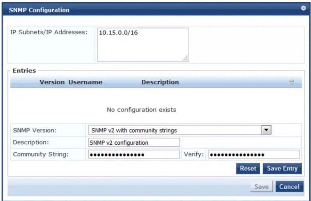
- Specify the SNMP Configuration parameters as described in Table 66. When finished, click Save Entry, then click Save.
Table 66: SNMP Configuration Parameters
| Field Action/Description | |
| IP Subnets/ IP Addresses | 1. Enter either one or more IP subnets or one or more IP addresses. For multiple entrieseparate multiple IP addresses with commas.When you initiate the network discovery scan, W-ClearPass will use the SNMP configuto fetch the network device information for discovered devices. |
| SNMP Version 2. | From the drop-down, select the appropriate SNMP version. |
| Description 3. Optionally, enter a description of this SNMP configuration (recommended). | |
| Community String | 4. Enter the community string, then reenter the community string in the Verify field. |
SSH Credentials Configuration
For Linux server or network device discovery, specify SSH (Secure Shell) configuration credentials. When S found for an IP address or subnet, Network Discovery looks for any Linux server or machine associated that IP address or subnet.
You can configure multiple user names and passwords. These credentials are organized in the order in the few they were created.
To configure SSH credentials for a network discovery scan:
The SSH configuration can be for a single IP address or a subnet. These credentials are used when an SSH scan is initiated.
- Navigate to Configuration > Profile Settings.
The Profile Settings page opens.
Figure 112: Profile Settings Page
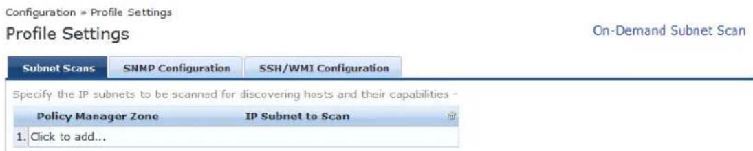
- Select the SSH Configuration tab.
Figure 113: SSH Configuration Tab

- Click Add Configuration.
The SSH Configuration page opens.

Figure 114: SSH Configuration Page
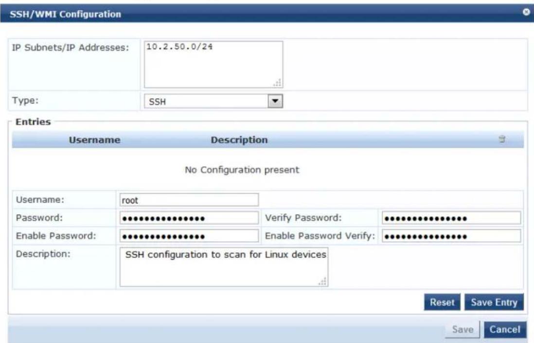
- Specify the parameters in the SSH Configuration dialog as described in the following table, then click Save Entry.
Table 67: SSH Configuration Parameters
| Field Action/Description | |
| IP Subnets/ IP Addresses | 1. Enter either one or more IP subnets or one or more IP addresses. For multiple entries, separate multiple IP addresses with commas. |
| Username 2. Enter the username for the device or subnet specified. | |
| Password 3. Enter the password for the device or subnet specified. | |
| Enable Password | 4. Enter the Enable password, then reenter the password in the Enable Password Verify field. |
| Description 5. Optionally, enter a description of this SNMP configuration (recommended). | |
-
Repeat this procedure for additional entries if needed.
-
When finished, click Save.
You return to the Profile Settings page, where you can see that the SSH configuration has been added successfully (see Figure 115).
Figure 115: SSH Configuration Added Successfully
Configuration » Profile Settings
Profile Settings
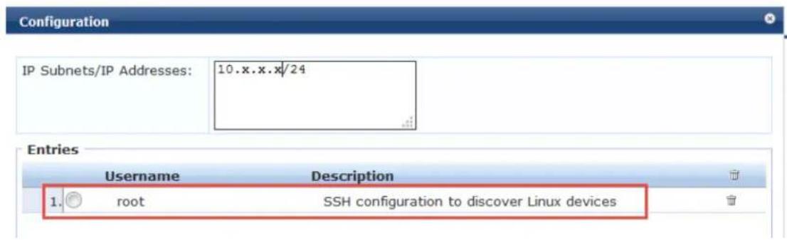
WMI Credentials Configuration
For Windows device discovery, specify WMI (Windows Management Instrumentation) configuration credentials. WMI configuration is necessary to discover Windows systems and device fingerprint details.
WMI a key part of the Windows operating system. It is used to gather system statistics, monitor system and manage system components. To work properly, WMI relies on the WMI service. This service must be running and properly configured for your environment.
For WMI, the login format for username is usually domain\username. Whatever domain you provide, it will be prepended to the username before logging into that machine.
Suppose you have provided an IP subnet address:
- W-ClearPass first checks to see if WMI is configured for that subnet/IP address.
- If WMI is configured, W-ClearPass checks to see if port 135 is open.
- If port 135 is open, W-ClearPass attempts the WMI login with those credentials.
If you provide just one IP address, the WMI login is performed for that particular IP address only.
To configure WMI credentials for a network discovery scan:
- Navigate to Configuration > Profile Settings.
The Profile Settings page opens.
Figure 116: Profile Settings Page

- Select the WMI Configuration tab.
Figure 117: WMI Configuration Tab

3. Click Add Configuration.
The WMI Configuration page opens.
Figure 118: WMI Configuration Page
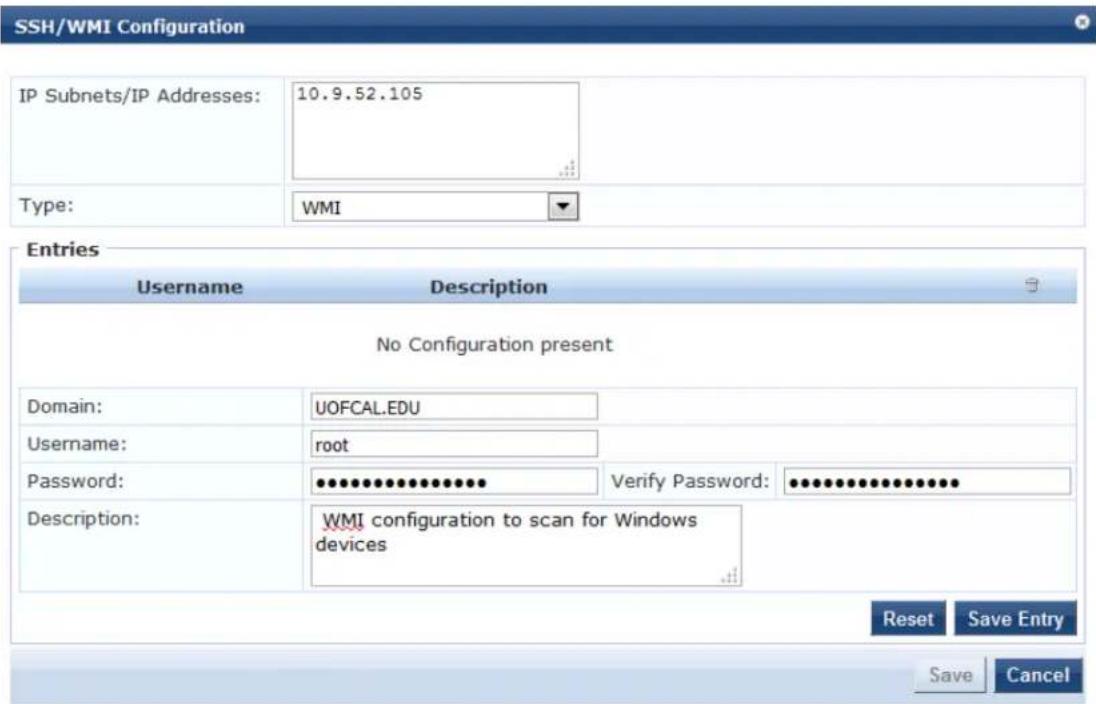
- Specify the WMI Configuration parameters as described in Table 68, then click Save Entry.
Table 68: WMI Configuration Parameters
| Field Action/Description | |
| IP Subnets/ IP Addresses | 1. Enter either one or more IP subnets or one or more IP addresses. For multiple entries, separate multiple IP addresses with commas.NOTE: The WMI configuration can be for a single IP address or a subnet. These credentials are used when a WMI scan is initiated. |
| Domain 2. Enter | the name of the Windows domain for logging into the device(s) that you are scanning. |
| Username 3. Enter the username for the device or subnet specified. | |
| Password 4. Enter the password for the device or subnet specified. | |
| Description 5. Optionally, enter a description of this SNMP configuration (recommended). | |
-
Repeat this procedure for additional entries if needed.
-
When finished, click Save.
You return to the Profile Settings page, where you can see that the WMI configuration has been added successfully (see Figure 119).
Figure 119: WMI Configuration Added Successfully
Configuration » Profile Settings
Profile Settings
SSH/WMI configuration added successfully
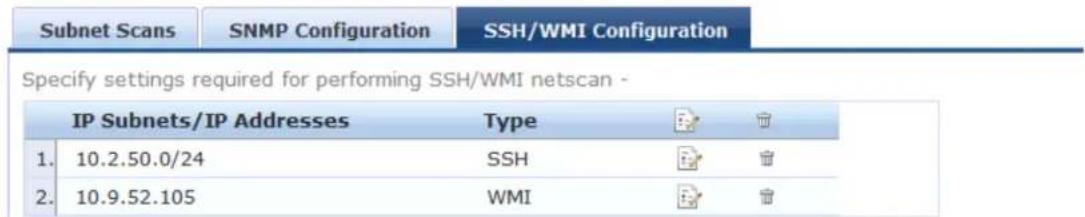
Initiating a Network Discovery Scan
Seed devices are the initial IP addresses provided by the network administrator to start the network scan.
When you initiate a network discovery scan and specify the seed devices, network discovery uses SNMP
• Find any other devices connected to the seed devices.
• Profile the connected devices.
- W-ClearPass uses that information to detect more devices in the network. The network discovery scan will proceed to the network depth specified by the Scan Depth parameter (described in Table 69 below).
- You can go to those devices and see their neighbor devices.
Running a network discovery scan on seed devices is a time- and resource-consuming operation. Depending on the number of devices associated with the seed device, a complete scan can take more than an hour.
It is recommended that the network scan should be done outside of normal business hours or performed on a W-ClearPass node that is not servicing core authentications.

To initiate a Network Discovery Scan:
- Navigate to Monitoring > Profiler and Discovery > Network Discovery.
The Network Discovery page opens.
Figure 120: Network Discovery Page
Monitoring » Profiler and Discovery » Network Discovery
Network Discovery
| # | Seed Devices | CPPM Server | Start Time 7 | End Time | Endpoints | Devices | Status | Action |
| 1. | 10.73.4.10 | cppm-66-b1 | 2015-11-18 03:28:34 | 2015-11-18 03:29:16 | 39 | 9 | COMPLETE | |
| 2. | 10.73.4.10 | cppm-66-b1 | 2015-11-17 19:32:23 | 2015-11-17 19:33:05 | 39 | 9 | COMPLETE | |
| 3. | 10.73.4.10 | cppm-66-b1 | 2015-11-17 19:24:16 | 2015-11-17 19:24:58 | 39 | 9 | COMPLETE | |
| 4. | 10.73.4.10 | cppm-66-b1 | 2015-11-17 19:20:31 | 2015-11-17 19:21:13 | 39 | 9 | COMPLETE | |
| 5. | 10.73.4.10 | cppm-66-b1 | 2015-11-17 19:06:03 | 2015-11-17 19:06:45 | 39 | 9 | COMPLETE | |
| 6. | 10.73.4.10 | cppm-66-b1 | 2015-11-17 18:46:45 | 2015-11-17 18:47:27 | 39 | 9 | COMPLETE | |
| Showing 1-5 of 6 | ||||||||
- Click Start Network Discovery Scan.
The Initiate Scan dialog opens.
Figure 121: Initiating the Seed Devices Scan
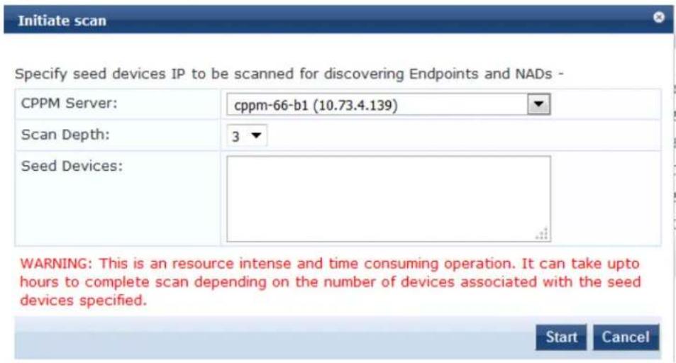
- Enter the appropriate information in the Initiate Scan dialog as described in Table 69.
Table 69: Initiating Network Discovery Scan Parameters
| Field Action/Description | |
| Server 1. From the drop-down list, select the W-ClearPass Policy Manager server.If the W-ClearPass server is in a cluster, the list will display the cluster node IP addresses that you can choose.NOTE: Once you select the node, the network discovery scan starts with that node. | |
| Scan Depth | 2. Specify the Scan Depth by selecting the desired number from 1 to 5.The Scan Depth numbers indicate the levels of the network you want to scan. The default is Scan Depth 3.The seed devices are, by default, at Scan Depth 1. Starting from the seed device, the next device level is Scan Depth 2, and so on, until the scan reaches the scan depth specified here. |
| Seed Devices 3. | Enter the IP addresses of one or more seed devices from which the network scan should proceed.Separate multiple device IP addresses with commas. |
- Click Start.
You return to the Network Discovery page, which now indicates the following:
■ The Start Time and End Time for the seed device scan.
■ The number of Endpoints and Devices connected to the seed device.
The Status of the scan operation, which shows initially as "Scheduled," then "In Progress," and finally, "Completed."
Figure 122: Seed Device Successfully Scanned
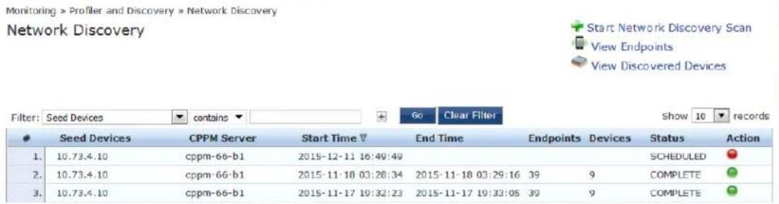
- You can stop a scheduled seed device scan or restart a completed scan:
a. To stop the scan operation, click the Red Action button, then click Yes to confirm the stop operation.
b. To restart a completed scan, click the Green Action button.
About Auto-Refresh
When Auto-Refresh is enabled (it is enabled by default), W-ClearPass fetches fresh data every few seconds to ensure that the network discovery scan status is always current.
When Auto-Refresh is enabled, the button is green. You can disable Auto-Refresh by clicking the button, which will then turn red to indicate this feature is disabled.
To enable or disable Auto Refresh:
- Navigate to Monitoring > Profiler and Discovery > Network Discovery.
Figure 123: Network Discovery > Auto Refresh
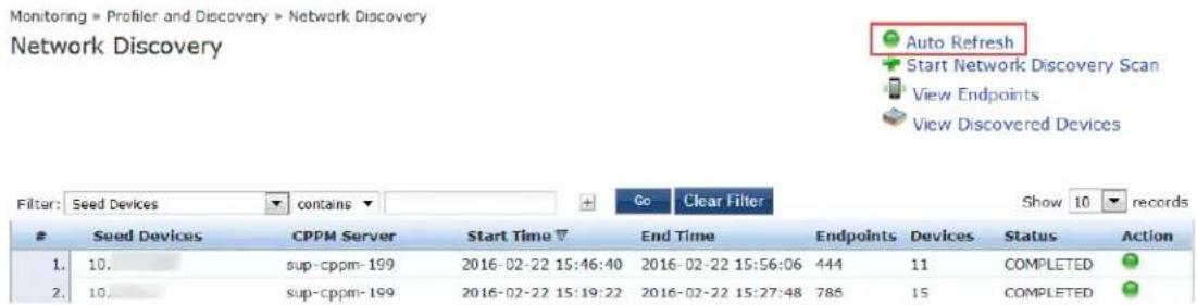
- Click the Auto Refresh link.
Every Auto-Refresh operation accesses the database and reads the data. When there is no network scan occurring, you can disable Auto-Refresh as there is no need to access the database every time.
Importing and Viewing Discovered Network Devices
To import and view discovered network devices:
- Navigate to Monitoring > Profiler and Discovery > Discovered Devices.
The Discovered Devices page opens.
Figure 124: Discovered Devices Page
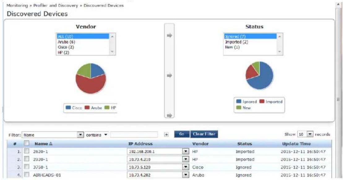
Importing Network Devices
The devices that you import are added to the set of network devices known to W-ClearPass.
You can import devices from the Publisher node only.
To import and add discovered devices to the set of W-ClearPass Network Devices:
-
From the list of discovered devices, select a device you wish to import (as shown in Figure 124). You can select all of the discovered devices at once by clicking the Name check box.
-
Click the Import button.
The Network Device Details dialog opens.
Figure 125: Importing a Network Device
![Network Device Details RADIUS Shared Secret: TACACS+ Shared Secret: Override Vendor: Enable RADIUS CoA: Verify: Verify: RADIUS CoA Port: 3799 Note: Names with special characters other than -, _, { }, [ ], ( ), dot and space will be replaced by underscore Import Cancel](/content/2026/05/842116/images/c7994bc0b4a08deb5e14b4bd21b57a3ef1ec12d1910421c82b03663820bce8e7.jpg)
- Enter the appropriate information in the Network Device Details dialog as described in Table 70.

Table 70: Specifying Network Device Details for Importing Devices
| Field Action/Description | |
| RADIUS Shared Secret | 1. If using RADIUS, enter the RADIUS Shared Secret for the selected discovered device. |
| TACACS+ Shared Secret | 2. If using TACACS+, enter the TACACS+ Shared Secret for the selected discovered device |
| Override Vendor | 3. Optionally, to override the discovered vendor type, select this check box. |
| Vendor This field | is displayed when you select Override Vendor.4. From the Vendor drop-down, select the name of the vendor type to override the dis vendor type. |
| Enable RADIUS CoA | 5. Select this check box to enable RADIUS CoA (Change of Authorization). |
| RADIUS CoA Port | The default RADIUS CoA port is 3799.6. To change the RADIUS CoA port number, enter the new port number. |
7. Click Import.
The selected network device has been added to W-ClearPass. To see the network device listed, naviga Configuration > Network > Devices.
Figure 126: Network Device Added to W-ClearPass
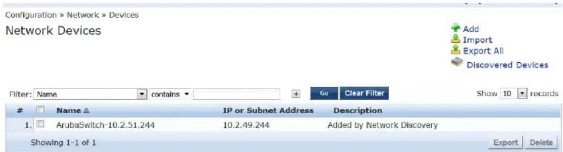
Viewing Details on a Discovered Device
To view detailed information about a discovered network devices, including a list of its neighbors in the network:
- Navigate to Monitoring > Profiler and Discovery > Discovered Devices.
The Discovered Devices page opens.
- Click the name of the device of interest.
The Network Device Details page opens.
Figure 127: Viewing Details fora Discovered Device
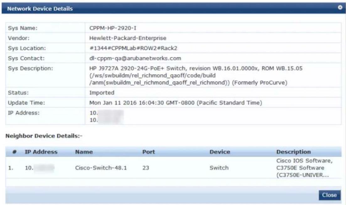
- When finished, click Close.
Viewing Discovered Endpoints
To view all the discovered endpoints that are connected to the network:
-
Navigate to Monitoring > Profiler and Discovery > Network Discovery. The Network Discovery page opens.
-
Click View Endpoints.
The Endpoint Profiler opens.
Figure 128: Viewing the Discovered Endpoints Information
Monitoring » Profiler and Discovery » Endpoint Profiler Endpoint Profiler
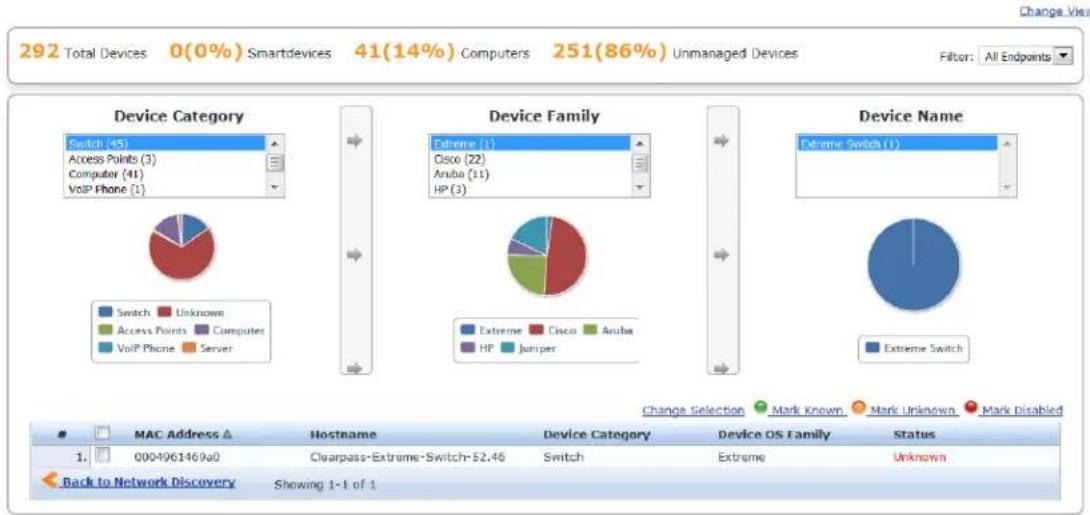
- When finished, click Back to Network Discovery.
Configuring Nmap-Based Endpoint Port Scans
The Network Discovery scan feature supports running an Nmap-based scan on a host to detect open po also to fingerprint the service(s) running behind those ports. This information is used in the device profil The steps to fully configure endpoint port scans using Nmap are as follows:
- Enable Nmap-based endpoint port scans.
a. Navigate to Administration > Server Manager > Server Configuration > Cluster-Wide Parameters.
The Cluster-Wide Parameters page opens.
b. Select the Profiler tab.
Figure 129: Cluster-Wide Parameters > Profiler Dialog
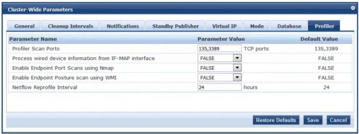
c. Set the Enable Endpoint Port Scans using Nmap parameter to TRUE.
For more information, see Profiler Parameters on page 561.
- Configure SNMP, SSH, WMI settings for the subnets.
a. Navigate to Configuration > Profile Settings.
b. Configure SNMP, SSH, WMI settings for the subnets (see Adding the Configurations to Query Seed Devices on page 154).
-
Initiate a network discovery scan configuring a seed device with Probe ARP entries enabled (see Initiating a Network Discovery Scan on page 160).
-
When the Network Discovery scan is completed, select an endpoint (see Viewing the List of Authentication Endpoints on page 259).
a. Navigate to Configuration > Identity > Endpoints.
b. Select the endpoint of interest.
- To view the list of host services and the list of open ports returned by the network discovery scan for selected host/endpoint, select the Fingerprints tab (see Figure 130).
Figure 130: Endpoint Fingerprint Details with Nmap Data
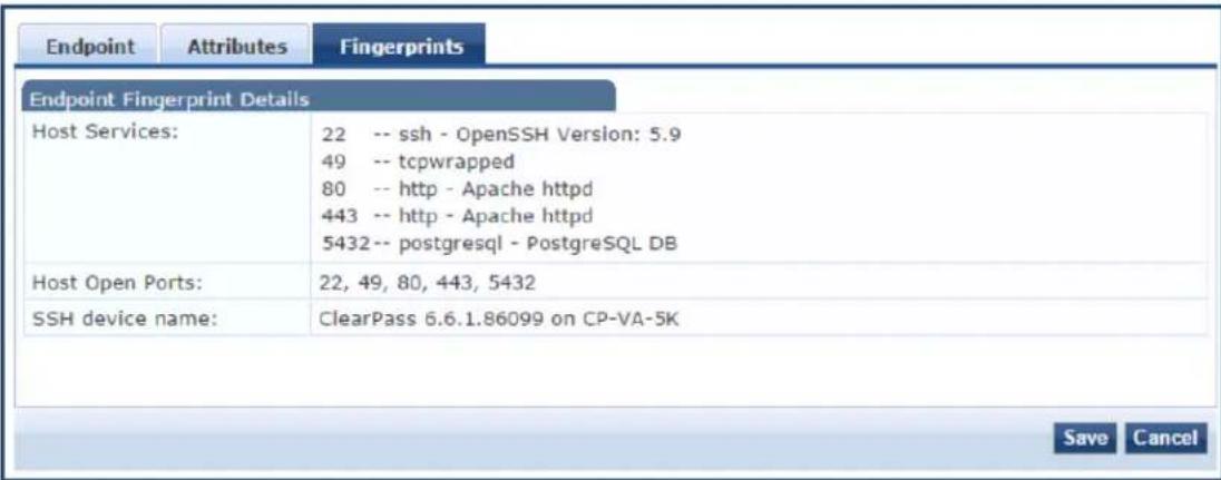
Audit Viewer
This section provides the following information:
- Introduction
- Audit Viewer
- Audit Viewer
- Audit Viewer
Introduction
The Audit Viewer page provides a dynamic report on actions, device name, category of Policy Manager component, user, and timestamp. To access the Audit Viewer:
- Navigate to Monitoring > Audit Viewer.
The Audit Viewer page opens.
Figure 131: Audit Viewer Page
Monitoring = Audit Viewer
Audit Viewer
| # | Action | Name | Category | User | Timestamp 7 |
| 21. | REMOVE | 01-02-03-04-05-06 | Guest User | admin | Jan 02, 2014 13:12:43 PST |
| 22. | MODIFY | 01-02-03-04-05-06 | Guest User | admin | Jan 02, 2014 13:11:23 PST |
| 23. | MODIFY | 01-02-03-04-05-06 | Guest User | admin | Jan 02, 2014 13:10:44 PST |
| 24. | MODIFY | 01-02-03-04-05-06 | Guest User | admin | Jan 02, 2014 13:10:17 PST |
| 25. | MODIFY | 01-02-03-04-05-06 | Guest User | admin | Jan 02, 2014 13:08:35 PST |
| 26. | MODIFY | 01-02-03-04-05-06 | Guest User | admin | Jan 02, 2014 13:08:24 PST |
| 27. | MODIFY | 01-02-03-04-05-06 | Guest User | admin | Jan 02, 2014 13:07:23 PST |
| 28. | MODIFY | 01-02-03-04-05-06 | Guest User | admin | Jan 02, 2014 13:05:58 PST |
| 29. | ADD | 9c207b1a566c | Endpoint | apradmin | Jan 02, 2014 12:43:46 PST |
| 30. | MODIFY | 9C-2D-7B-A7-SA-24 | Guest User | admin | Jan 02, 2014 12:01:20 PST |
- To display detailed information about the selected event, click any row in the audit viewer.
The Audit Row Details page opens (see ).
The content in the Audit Row Details page varies, depending upon type of event you select.
Add Events
To display additional details that are specific to the new policy component, click a row with the Add action type.
The Audit Row Details page opens.
Figure 132: Audit Row Details for Add Event
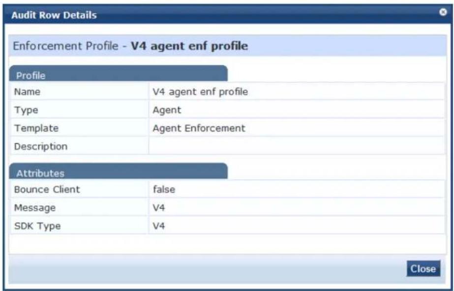
For example, if a TACACS enforcement profile is added, the Audit Row Details page displays detailed information about that profile.
If a policy is created, the Audit Row Details page displays information about the policy.
Modify Events
To display additional details information about the change, including the previous values, the latest, upda values, and the differences between the two, click a row with the Modify action type.
Figure 133 shows the Audit Row Details page for a Modify Event.
Figure 133: Audit Row Details for Modify Event
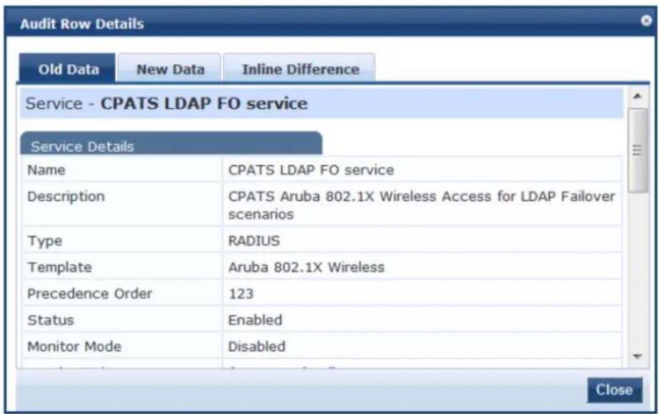
When you view a modify event, the Audit Row Details window contains the following three tabs:
Table 71: Audit Row Details > Modify Event Page
| Parameter Description | |
| Old Data Displays a | summary of details about the original data values.TheProfilesection shows a summary of the profile values.TheAttributessection shows data about the original attributes and values. |
| New Data Displays a | summary of details about the new data values.TheProfilesection shows a summary of the profile values.TheAttributessection shows data about the original attributes and values. |
| Inline Difference Displays information about what changed. The information is color-coded to indicate the following types of changes:ModifiedAddedDeletedMoved upMoved down | |
Remove Events
To display details about attributes that were removed, click a row with the Remove action type.
Event Viewer
This section provides the following information:
• About the Event Viewer
- Creating an Event Viewer Report Using Default Values
- Creating an Event Viewer Report Using Custom Values
• Viewing Report Details
About the Event Viewer
The Event Viewer page provides reports about system-level events. All attempted upgrade, patch, and hotfix installations are logged in the Event Viewer, including failed system installation attempts.
Session Idle time-out values for Admin WebUI session time-out and CLI session time-out events generate Viewer messages with a description that includes the client IP address and session ID when necessary.
Unsupported Admin Access Attempts Logged to the Event Viewer
If an attempt is made to access W-ClearPass Policy Manager administration command-line interface (CLI) unsupported SSH protocol versions, or unsupported encryption or cryptographic hash algorithms, W-ClearF logs those alerts in the Event Viewer. This feature requires the Ingress Event Engine option and services to be enabled (for details, see Enabling Ingress Events Processing on page 736).
If an attempt is made to access W-ClearPass Policy Manager administration WebUI with unsupported SSL protocol versions, or unsupported ciphers, W-ClearPass logs those alerts in the Event Viewer. This feature requires the Ingress Event Engine option and services to be enabled for the W-ClearPass server (for details, see Enable Ingress Events Processing on page 500).
To access the Event Viewer:
- Navigate to Monitoring > Event Viewer.
The Event Viewer page opens.
Figure 134: Event Viewer Page
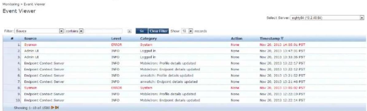
The following table describes the Event Viewer parameters:
Table 72: Event Viewer Page Parameters
| Parameter Description | |
| Source Displays the source of the event. For example, AdminUI or W-ClearPass Updater. | |
| Level Displays the level of the event from the following options:INFOWARNERROR | |
| Category | Displays the category of the event. For example, Logged in, System, or AV/AS Updates. |
| Action Displays the status of the event action. For example, Success, Failed, Unknown, and None. | |
| Timestamp Displays the date and time when the event occurred. | |
Creating an Event Viewer Report Using Default Values
- In the Filter field, select Source as the filter parameter.
- Click Go.
W-ClearPass returns all event records.
Creating an Event Viewer Report Using Custom Values
- Click the icon.
A new filter is added. You can add up to four filters. - Click Select ANY match.
- In the first Filter field, select Level.
- Leave the search term set to contains.
- Enter ERROR in the text field.
- In the second Filter field, select Source.
- Change the search field to equals.
- Enter SYSMON in the text field.
- Change the Show records value to 20.
10.Click Go.
The following figure displays the Event Viewer report with custom values:
Figure 135: Event Viewer Report with Customized Filter
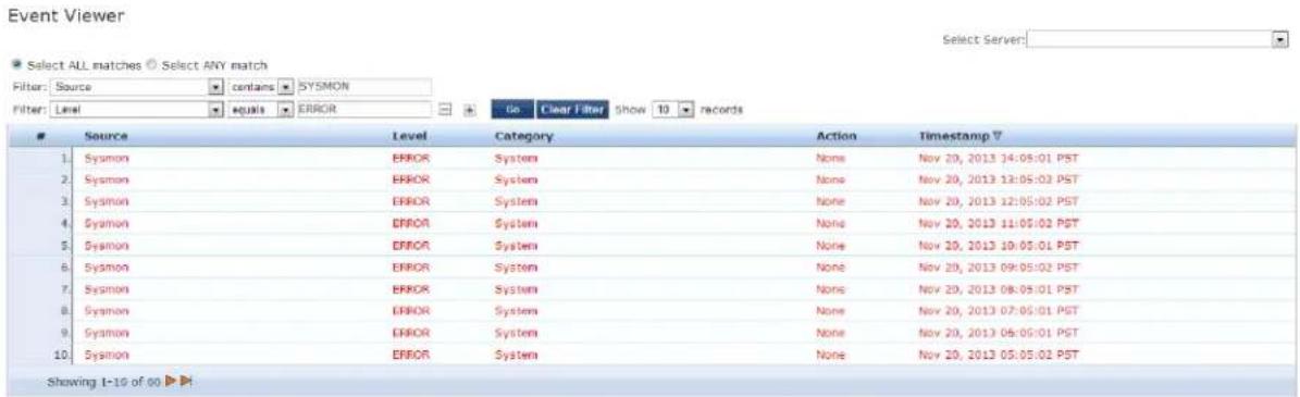
Viewing Report Details
To display the System Event Details page, click a row in the Event Viewer page.
Figure 136: System Event Details Page
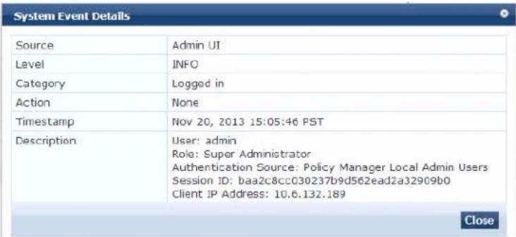
The following table describes the System Event Details parameters:
Table 73: System Event Details Page Parameters
| Parameter Description | |
| Source Displays the source of the event. For example, Admin UI, RADIUS, and SnmpService. | |
| Level Displays the level of the event from the following options:INFOWARNERROR | |
| Category | Displays the category of the event. For example, Request, Authentication, and System. |
| Action | Displays the action of the events. For example, Success, Failed, Unknown, and None. |
| Timestamp | Displays the date and time when the event occurred. |
| Description | Displays additional information about the event, including the session ID, client IP address when pertinent, and the session inactive expiry time. |
Data Filters
This section provides the following information:
- About Data Filters
- Adding a Data Filter
About Data Filters
The Data Filters page provides a way to limit the number of rows of data shown by defining custom criteria or rules in the following components in Policy Manager:
• Live Monitoring: Access Tracker on page 117
• Syslog Export Filters on page 591
• Live Monitoring: Analysis and Trending on page 146
• Live Monitoring: Accounting on page 129
Preconfigured Data Filters
Policy Manager is preconfigured with the following data filters:
Table 74: Access Tracker Edit Page Parameters
| Data Filter Description | |
| RADIUS Requests Shows all RADIUS requests. | |
| TACACS Requests Shows all TACACS requests. | |
| WebAuth Requests Shows all Web Authentication requests (requests originated from the Guest Portal). | |
| Event Requests Displays all event-based records. | |
| Failed Requests Shows all authentication requests that were rejected or faile | |
| Successful Requests Shows all authentication requests that were successful. | |
| Unhealthy Requests Shows all requests that were not deemed healthy by Policy Manager. | |
| Healthy Requests Shows all requests that were deemed healthy by Policy Manager. | |
| Guest Access Requests | Shows all requests—RADIUS or Web Authentication—where the user was assigned the built-in role Guest. |
| W-ClearPass Application Requests | Shows all Application session log requests. |
| All Requests | Shows all requests (without any rows filtered). |
Accessing the Data Filters Page
To access the Data Filters page:
- Navigate to Monitoring > Data Filters.
The Data Filters page opens.
Figure 137: Data Filters Page
![Monitoring > Data Filters Data Filters Filter: Name contains Go Clear Filter Show 10 records Name ▲ Description 1. [Active sessions] All Active sessions 2. [All Requests] All session log requests 3. [ClearPass Application Requests] All Application session log requests 4. eduroam-SMU-users breakdown eduroam to SMU and Foreign users 5. [Failed Requests] All Failed session log requests 6. [Guest Access Requests] All Guest Login requests 7. [Healthy Requests] All Healthy session log requests 8. [RADIUS Requests] All RADIUS requests 9. [Successful Requests] All Successful session log requests 10. [TACACS Requests] All TACACS requests Showing 1-10 of 12 ▶ Copy Export Delete](/content/2026/05/842116/images/a07d3e44c40be9b95bd3fab51915010b33e500fa599ad1e2226db980fada6336.jpg)
Adding a Data Filter
To add a data filter:
- Click the Add link in the top-right corner of the page.
The Add Data Filters page opens to the Filter tab.
Figure 138 shows the Filter dialog when you choose Select Attributes.
Figure 138: Add Data Filter > Filter Tab > Select Attributes
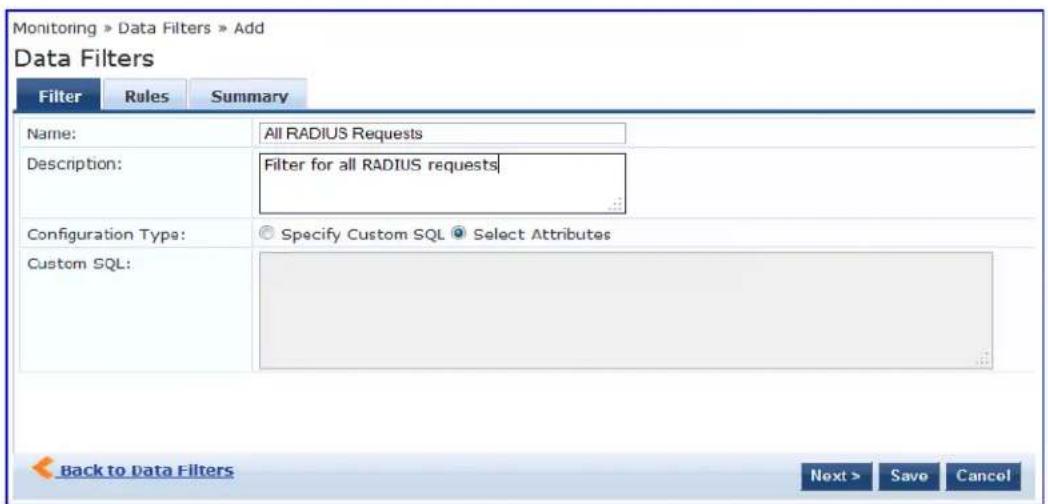
Figure 139 shows the Filter dialog when you choose Specify Custom SQL.
Figure 139: Add Data Filter > Filter Tab > Specify Custom SQL
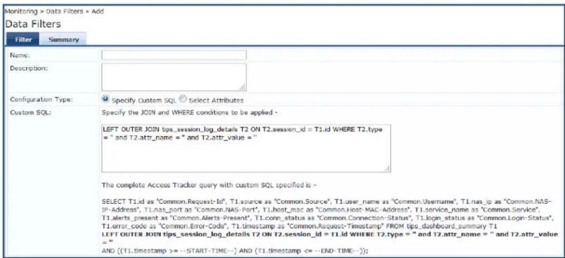
- Specify the Add Data Filters parameters as described in the following table.
Table 75: Add Data Filters Page > Filter Tab Parameters
| Parameter Action/Description | |
| Name Enter a name for the data filter. | |
| Description Optionally,enter a description of this data filter (recommended). | |
| Configuration Type Choose one of the following configuration types:Select AttributesSpecify Custom SQL | |
| Select Attributes | This option is selected by default. When you specify Select Attributes, the Rules tab appears.Use the Rules tab to configure rules for this filter. |
| Specify Custom SQL | When you choose Specify Custom SQL, a default SQL template is displayed.In the text entry field, enter the attributes for the type, attribute name, and attribute value.NOTE: Dell does not recommend that you enable this option without first consulting Support (navigate to Administration >Support >Contact Support). |
Rules Tab
The Rules tab displays when you choose the Select Attributes configuration type on the Filter dialog.
Figure 140: Add Data Filter > Rules Dialog
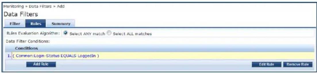
Table 76 describes the Add Filter > Rules tab parameters:
Table 76: Add Filter > Rules Tab
| Parameter Action/Description | |
| Rule Evaluation Algorithm | Select ANY match is a logical OR operation of all the rules. Select ALL matches is a logical AND operation of all the rules. |
| Add Rule Add a rule to the filter. | |
| Edit Rule Edit an existing rule. | |
| Remove Rule | When you select an existing rule and click Remove Rule, the selected Rule is deleted immediately (no confirmation prompt appears). |
When you click Add Rule or Edit Rule, the Dashboard Filter Rules Editor dialog opens.
Figure 141: Dashboard Filters > Rules Editor
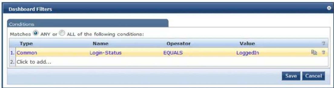
Table 77 describes the Dashboard Filters > Rules Editor parameters:
Table 77: Dashboard Filters > Rules Editor Configuration Parameters
| Parameter | Action/Description |
| Matches Specify the match conditions:ANY matches one of the configured conditions.ALL specifies to match all of the configured conditions. | |
| Type Select the type of data filter.Common: Attributes common to RADIUS, TACACS, and WebAuth requests and responses.RADIUS: Attributes associated with RADIUS authentication, accounting requests, and responses.TACACS: Attributes associated with TACACS authentication, accounting, policy requests, and responses.Web Authentication Policy: Policy Manager policy objects assigned after the evaluation of policies associated with Web Authentication requests. For example, Auth Method, Auth Source, and Enforcement Profiles. | |
| Name Select the name of the attribute from the Name drop-down list.The Name list varies according to which Type you selected. | |
| Operator Select any subset of string data type operators from the following list:EQUALSNOT_EQUALSLESS_THANLESS_THAN_OR_EQUALSGREATER_THANGREATER_THAN_OR_EQUALSCONTAINSNOT_CONTAINSEXISTSSNOT_EXISTS | |
| Value The value of the attribute. | |
Restoring Blacklisted Users to the Network
The Blacklisted Users page lists the MAC address and user name of all blacklisted users, the authentication source for that user, and indicates whether the bandwidth limit or session duration limits were exceeded each blacklisted user.
After a user entry is removed from the blacklisted users list, the user is eligible to access the network.
To access the Blacklisted Users page:
- Navigate to Monitoring > Blacklisted Users.
Figure 142: Blacklisted Users Page
![Filter: MAC Address - contains + Co Clear Filter Show 20 records MAC Address User Name Authentication Source Bandwidth Limit Session Duration Timestamp △ 1. FB0755E2BDC0 user1 [Local User Repository] Exceeded Exceeded Aug 19, 2013 19:20:23 IST 2. 7871C5B3793D user2 [Guest User Repository] Exceeded Not Exceeded Aug 19, 2013 19:20:23 IST 3. 06507A6574FB user3 [Guest Device Repository] Exceeded Exceeded Aug 19, 2013 19:20:23 IST 4. 5F39EA4CCF35 user4 [Endpoint's Repository] Not Exceeded Exceeded Aug 19, 2013 19:20:23 IST 5. BD2813331857 user5 [Onboard Devices Repository] Exceeded Not Exceeded Aug 19, 2013 19:20:23 IST 6. FE1AFE26D551 user6 [Admin User Repository] Not Exceeded Exceeded Aug 19, 2013 19:20:23 IST 7. C8CB61D93511 user7 [Blacklist User Repository] Exceeded Exceeded Aug 19, 2013 19:20:23 IST 8. E17CJB06FF62 user8 [Insight Repository] Exceeded Not Exceeded Aug 19, 2013 19:20:23 IST 9. F5F920B10173 user9 [Local User Repository] Not Exceeded Not Exceeded Aug 19, 2013 19:20:23 IST 10. A8D394659CF3 user10 [Guest User Repository] Not Exceeded Exceeded Aug 19, 2013 19:20:23 IST 11. B249A5FC722A user11 [Guest Device Repository] Exceeded Exceeded Aug 19, 2013 19:20:23 IST Showing 1-11 of 11 Delete](/content/2026/05/842116/images/6c898e37ef0a3f56e116127581c11002803239a3865dd25a63c5abfe512114b2.jpg)
- To delete a user from this blacklist, select the user row and click Delete.
The deleted Blacklisted user is now eligible to access the network.
This section provides the following information:
• Supported Authentication Methods on page 179
- Adding and Configuring Authentication Methods on page 183
- Adding and Configuring Authentication Sources on page 207
- Configuring Authentication Methods for an Existing Service on page 181
Supported Authentication Methods
As a first step in the service-based processing, Policy Manager uses an authentication method to authent the user or device against an authentication source.
After the user or device is authenticated, Policy Manager fetches attributes for role-mapping policies from authorization sources associated with this authentication source. For a general overview of Policy Manager authentication and authorization, see Authentication and Authorization Architecture and Flow on page 1.
W-ClearPass Policy Manager supports the following authentication methods:
Tunneled EAP Authentication Methods
• EAP Protected EAP (EAP-PEAP)
• EAP Flexible Authentication Secure Tunnel (EAP-FAST)
• EAP Transport Layer Security (EAP-TLS)
• EAP Tunneled TLS (EAP-TTLS)
Non-Tunneled Authentication Methods
• EAP Message Digest 5 (EAP-MD5)
• EAP Microsoft Challenge Handshake Authentication Protocol version 2 (EAP-MSCHAPv2)
• EAP Generic Token Card (EAP-GTC)
• Challenge Handshake Authentication Protocol (CHAP)
- Password Authentication Protocol (PAP)
• Microsoft CHAP version 1 and 2
• MAC authentication method (MAC-AUTH)
• Authorize authentication
Authentication and Authorization Architecture and Flow
This section includes the following information:
• Authentication Method
• Authentication Source
• Authorization Source
• Authentication and Authorization Flow of Control
Policy Manager divides the architecture of authentication and authorization into the following three components:
• Authentication method
• Authentication source
• Authorization source
Authentication Method
Policy Manager initiates the authentication handshake by sending available methods in a priority order ur the client accepts a method or until the client rejects the last method with the following possible outcon
- Successful negotiation returns a method, which is used to authenticate the client against the authentication source.
- Where no method is specified (for example, for unmanageable devices), Policy Manager passes the request to the next configured policy component for this service.
• Policy Manager rejects the connection.

An authentication method is configurable only for some service types. For more information, see Configuring Policy Manager Services on page 72. All 802.1X wired and wireless services have an associated authentication method.
Authentication Source
In Policy Manager, an authentication source is the identity store (Active Directory, LDAP directory, SQL DE token server, etc.) against which users and devices are authenticated.
Policy Manager first tests whether the connecting entity (the device or user) is present in the ordered list configured authentication sources.
Policy Manager looks for the device or user by executing the first filter associated with the authentication source. After the device or user is found, Policy Manager then authenticates this entity against this authentication source. The flow is as follows:
- On successful authentication, Policy Manager moves on to the next stage of policy evaluation, which collects role mapping attributes from the authorization sources.
- Where no authentication source is specified (for example, for unmanageable devices), Policy Manager passes the request to the next configured policy component for this service.
- If Policy Manager does not find the connecting entity in any of the configured authentication sources, it rejects the request.
Authorization Source
After Policy Manager successfully authenticates the user or device against an authentication source, it reti role-mapping attributes from each of the authorization sources configured for that authentication source. It also, optionally, can retrieve attributes from authorization sources configured for the service.
Authentication and Authorization Flow of Control
The flow of control for authentication takes the following components in sequence:
Figure 143: Authentication and Authorization Flow of Control
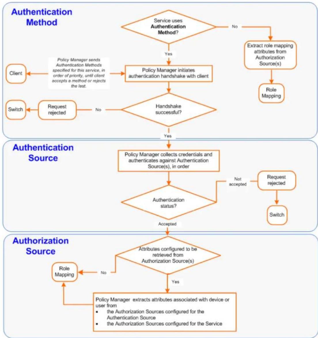
flowchart
graph TD
    A["Authentication Method"] --> B{Service uses Authentication Method?}
    B -->|Yes| C["Policy Manager initiates authentication handshake with client"]
    B -->|No| D["Extract role mapping attributes from Authorization Source(s)"]
    C --> E{Handshake successful?}
    E -->|Yes| F["Policy Manager collects credentials and authenticates against Authentication Source(s), in order"]
    E -->|No| G["Request rejected"]
    F --> H{Authentication status?}
    H -->|Not accepted| I["Request rejected"]
    H -->|Accepted| J{Attributes configured to be retrieved from Authorization Source(s)}
    I --> K["Switch"]
    J -->|No| L["Role Mapping"]
    J -->|Yes| M["Policy Manager extracts attributes associated with device or user from the Authorization Sources configured for the Authentication Source, the Authorization Sources configured for the Service"]
    N["Client"] --> C
    O["Switch"] --> P["Request rejected"]
Configuring Authentication Methods for an Existing Service
To add or modify an authentication method or source for an existing service:
- Navigate to the Configuration > Services page, then click Add.
The Add Services page opens.
- Select the Authentication tab.
The Add Services > Authentication dialog opens:
Figure 144: Specifying Authentication Methods and Sources for a Selected Service
![Configuration > Services > Add Services Service Authentication Roles Enforcement Summary Authentication Methods: [EAP PEAP] [EAP FAST] [EAP TLS] [EAP TTLS] [EAP MSCHAPV2] ($50) --Select to Add-- Add new Authentication Method Authentication Sources: [Admin User Repository] [Local SQL DB] [Insight Repository] [Local SQL DB] [Global Large Repository] [Local SQL DB] --Select to Add-- Move Up Move Down Remove View Details Modify Add new Authentication Source Strip Username Rules: Enable to specify a comma-separated list of rules to strip username prefixes or suffixes](/content/2026/05/842116/images/1a334c43bc22de7fcbe101ce30d7dc9f04d3096ae7077e15901d45bcd1f57045.jpg)
- Specify the Authentication methods and sources for the selected service as described in the following You can open an authentication method or source from the Configuration > Authentication > Methods or Configuration > Authentication > Sources page.
Table 78: Authentication Configuration at the Service Level
| Component Configuration Steps | |
| Sequence of Authentication Methods | Select a method, then selectMove Up, Move Down, or Remove.SelectView Detailsto view the details of the selected method.SelectModifyto modify the selected authentication method. This displays a popup with the edit widgets for the select authentication method.To add a previously configured authentication method, select from theSelect to Adddrop-down list.To configure a new method, click theAdd new Authentication Methodlink. For more information about authentication methods, see Adding and Configuring Authentication Methods on page 183.NOTE:An authentication method is only configurable for some service types. For more information, refer toConfiguring Policy Manager Services on page 72. |
| Sequence of Authentication Sources | Select a source, thenMove Up, Move Down, or Remove.SelectView Detailsto view the details of the selected authentication source.SelectModifyto modify the selected authentication source. This displays theAuthentication Source Configurationwizard for the selected authentication sourceTo add a previously configured authentication source, select from theSelect to Adddrop-down list.To configure a new authentication source, click theAdd new Authentication Source link. For more information about authentication sources, see Adding and Configuring Authentication Sources on page 207. |
| Whether to standardize the form in which usernames are present | Select theEnable to specify a comma-separated list of rules to strip usernames check box to pre-process the user name and to remove prefixes and suffixes before authenticating it to the authentication source. |
Adding and Configuring Authentication Methods
This section provides the following information:
- Adding a New Authentication Method
• Modifying an Existing Authentication Method
Adding a New Authentication Method
To add a new authentication method:
- Navigate to Configuration > Authentication > Methods.
The Authentication Methods page opens.
Figure 145: Authentication Methods Page
![Configuration > Authentication > Methods Authentication Methods Filter: Name contains Go Clear Filter Show 10 records Name ▲ Type Description 1. [Allow All MAC AUTH] MAC-AUTH Default settings for Allow All MAC-AUTH 2. [Aruba EAP GTC] EAP-GTC EAP-GTC method to use with Aruba EAP-GTC plugin for Windows 3. [Authorize] Authorize Default settings for Authorize 4. [CHAP] CHAP Default settings for CHAP 5. [EAP FAST] EAP-FAST Default settings for EAP-FAST 6. [EAP GTC] EAP-GTC Default settings for EAP-GTC 7. [EAP MDS] EAP-MDS Default settings for EAP-MDS 8. [EAP MSCHAPv2] EAP-MSCHAPv2 Default settings for EAP-MSCHAPv2 9. [EAP PEAP] EAP-PEAP Default settings for EAP-PEAP 10. [EAP PEAP Public] EAP-PEAP-Public Default settings for EAP-PEAP-Public Showing 1-10 of 19 ► Export Delete](/content/2026/05/842116/images/1e5da7443ef725d49bf699ab3b32c4d10a9f0e88fbe2b31884d7e2915b4b7dd0.jpg)
- Click Add.
The Add Authentication Method page opens.
Figure 146: Add Authentication Method Page
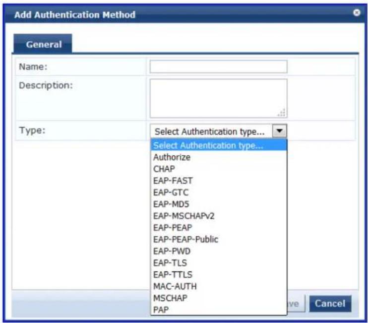
- Enter the name and description of the new authentication method.
- From the Type drop-down, select the type of authentication type.
You can select from the following list of Authentication types:
-
Authorize
■ CHAP (Challenge Handshake Authentication Protocol)
■ EAP-FAST (Extensible Authentication Protocol-Flexible Authentication via Secure Tunneling)
■ EAP-GTC (EAP-Generic Token Card)
■ EAP-MD5 (EAP-Message Digest 5)
■ EAP-MSCHAPv2 (EAP-Microsoft Challenge Handshake Authentication Protocol version 2)
■ EAP-PEAP (EAP-Protected Extensible Authentication Protocol)
EAP-PEAP-Public
■ EAP-PWD (EAP-Password)
■ EAP-TLS (EAP-Transport Layer Security)
■ EAP-TTLS (EAP-Tunneled Transport Layer Security)
■ MAC-AUTH (MAC Address Authentication)
■ MSCHAP (Microsoft Challenge Handshake Authentication Protocol version 1)
■ PAP (Password Authentication Protocol) -
Configure the Authentication Method of interest as described in the following sections:
■ Authorize Authentication Method on page 185
■ CHAP Authentication Method on page 186
■ EAP-FAST Authentication Method on page 187
■ EAP-GTC Authentication Method on page 192
■ EAP-MSCHAPv2 on page 193
■ EAP-PEAP on page 194
■ EAP-PEAP-Public on page 196
■ EAP-PWD on page 199
■ EAP-TLS on page 200
■ EAP-TTLS on page 202
■ MAC-AUTH Authentication Method on page 204
■ MSCHAP on page 205
■ PAP on page 206
Modifying an Existing Authentication Method
To modify an existing authentication method:
- Navigate to Configuration > Authentication > Methods.
The Authentication Methods page opens.
- Click the authentication method of interest.
The Edit Authentication Method page opens.
Figure 147: Edit Authentication Method Page (EAP-FAST)
![Edit Authentication Method General Inner Methods PACs PAC Provisioning Name: [EAP FAST] Description: Default settings for EAP-FAST Type: EAP-FAST Method Details Session Resumption: Enable Session Timeout: 6 hours End-Host Authentication: Using PACs Certificate Comparison: Do not compare Copy Save Cancel](/content/2026/05/842116/images/ada3c3d1da55e14a685b7d3278f51c6e291881367e8b43c96f82c5a4e6e3e0cd.jpg)
- Modify the selected authentication method(s) as necessary, then click Save.
Authorize Authentication Method
This is an authorization-only method that you can add with a custom name.
To add the Authorize authentication method:
- Navigate to Configuration > Authentication > Methods.
The Authentication Methods page opens.
- Click Add.
The Add Authentication Method configuration dialog opens:
Figure 148: Add Authorize Authentication Method Configuration Dialog
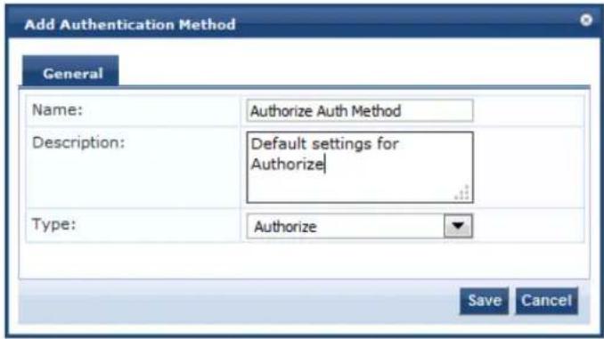
- Specify the Authorize Authentication Method parameters as described in the following table:
Table 79: Authorize Authentication Method Parameters
| Parameter Action/Description | |
| Name Specify the label of the authentication method. | |
| Description Provide additional information that helps to identify the authentication method. | |
| Type Select authentication method type Authorize. |
- Click Save.
CHAP Authentication Method
Policy Manager is packaged with the Challenge-Handshake Authentication Protocol (CHAP) authentication method. You can create one or more instances of the CHAP authentication method by assigning a customized name to each one. This method can also be associated to a service as an authet method.
To add the CHAP authentication method:
- Navigate to Configuration > Authentication > Methods.
The Authentication Methods page opens.
- Click Add.
The Add Authentication Method configuration dialog opens:
Figure 149: Adding CHAP Authentication Method
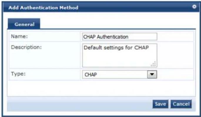
- Specify the CHAP parameters as described in the following table:
Table 80: CHAP Parameters
| Parameter Description |
| Name Specify the name of the CHAP authentication method. |
| Description Provide the additional information that helps to identify the authentication method. |
| Type Select CHAP. |
- Click Save.
EAP-FAST Authentication Method
- General Tab
• Inner Methods Tab - PACs Tab
• PAC Provisioning Tab
EAP-FAST (Flexible Authentication through Secure Tunneling) is an authentication method that encrypts EA transactions within a TLS (Transport Layer Security) tunnel.
General Tab
To add the EAP-FAST authentication method to W-ClearPass:
-
Navigate to Configuration > Authentication > Methods.
The Authentication Methods page opens. -
Select the Add link.
The Add Authentication Method dialog opens to the General tab.
Figure 150: Adding the EAP-FAST Authentication Method
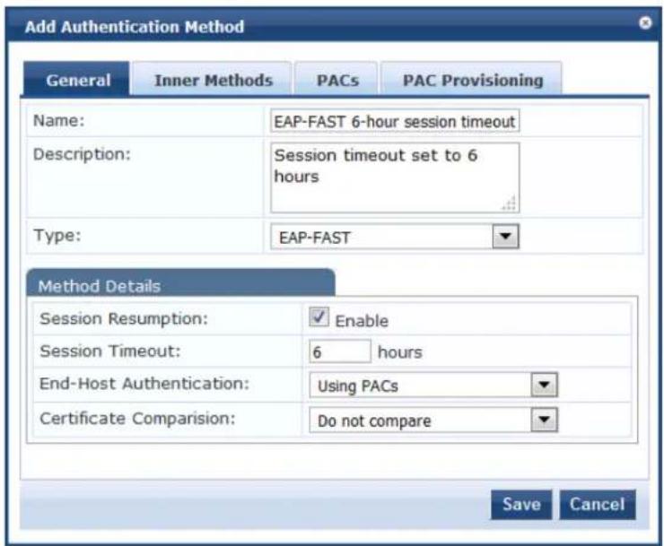
- Configure the EAP-FAST authentication service as described in Table 81.
Table 81: Specifying the EAP-FAST > General Parameters
| Parameter Action/Description | |
| Name Specify the name of the authentication method. | |
| Description Provide | the additional information that helps to identify the authentication method. |
| Type Select EAP-FAST. | |
| Session Resumption | Caches EAP-FAST sessions on Policy Manager for reuse if the user/end-host reconnects the W-ClearPass server within the session-timeout interval. By default, this option is enabled. |
| Session Timeout Caches | EAP-FAST sessions on Policy Manager for reuse if the user/end-host reconnects to Policy Manager within the session-timeout interval.Specify the Session Timeout in the number of hours.The default is 6 hours.If the Session Timeout value is set to 0, the cached sessions are not purged. |
| End-Host Authentication | Specify one of the following end-host authentication methods:Using PACS (Protected Access Credentials)Using Client CertificateNOTE:The PACs and PAC Provisioning tabs are available only when you select Using PACs. |
| Certificate Comparison | Specify one of the following Certificate Comparison actions:Do not compareCompare Distinguished Name (DN)Compare Common Name (CN)Compare Subject Altername Subject Name (SAN)Compare CN or SANCompare Binary |
4. Click Save.
Inner Methods Tab
The following figure displays the EAP-FAST > Inner Methods dialog:
Figure 151: EAP-FAST Authentication Method > Inner Methods Dialog
 [EAP MD5] --Select a method-- To set preference for a specific method, use Default button Default Remove Save Cancel](/content/2026/05/842116/images/c494014f6db833384050ffa7bf5570903376479bccc4505dbfbf8fb169f082ea.jpg)

In FIPS mode, the EAP-MD5 authentication method is not supported.
Table 82: EAP-FAST > Inner Methods Tab Parameters
| Parameter Action/Description | |
| Specify inner authentication methods in the preferred order | Select a method from the drop-down list:Dell EAP GTCEAP GTCEAP MD5EAP MSCHAPV2 (Default)EAP PWDEAP TLS with OSCP EnabledEAP TLSFunctions available in this tab include:To append an inner method to the displayed list, select from the Select a method drop-down list. The list can contain multiple inner methods, which Policy Manager sends in priority order until negotiation succeeds.To remove an inner method from the displayed list, select the method and Remove.To set an inner method as the default inner method (the method tried fi select a method and click Default. |
PACs Tab
The PACs dialog enables or disables Protected Access Credential (PAC) types. The following figure displays the EAP-FAST > PACs dialog:
Figure 152: EAP_FAST PACs Dialog
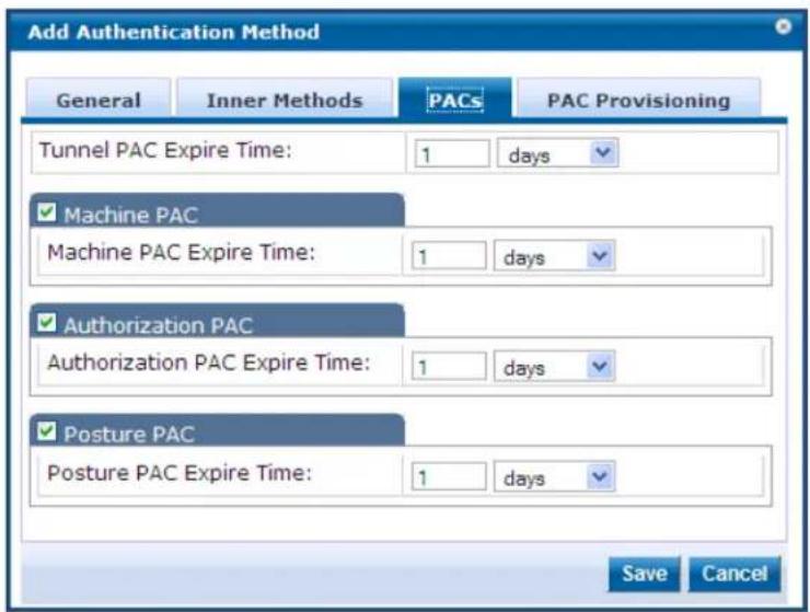
- Specify the Expiration Time (number of hours, days, weeks, months, or years) for each of the Protected Access Credentials:
a. Tunnel PAC Expire Time
b. Machine PAC Expire Time
c. Authorization PAC Expire Time
d. Posture PAC Expire Time
- Select the PAC Provisioning tab.
PAC Provisioning Tab
The PAC Provisioning dialog controls anonymous and authenticated modes. The following figure displays the EAP-FAST PAC > Provisioning dialog:
Figure 153: EAP_FAST PAC Provisioning Dialog
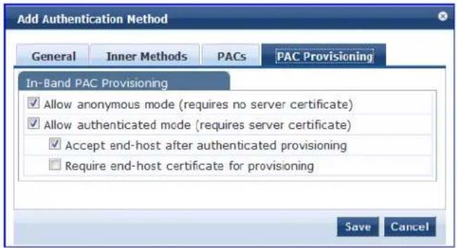
-
Configure the PAC Provisioning parameters as described in Table 83.
-
When finished, click Save.
Table 83: EAP_FAST PAC Provisioning Parameters
| Parameter Action/Description Considerations | ||
| In-Band PAC Provisioning | ||
| Allow anonymous mode | When in anonymous mode, phase 0 of EAP_FAST provisioning establishes an outer tunnel without end-host/Policy Manager authentication.NOTE: This mode is not as secure as the authenticated mode. After an outer tunnel is established, the end-host and Policy Manager perform mutual authentication using MSCHAPv2, then Policy Manager provisions the end-host with an appropriate PAC (tunnel or machine). | Authenticated mode is more secure than anonymous provisioning mode. After the server is authenticated, the phase 0 tunnel established. The end-host and Policy Manager perform mutual authentication and provision on the end-host with an appropriate PAC (tunnel or machine):If both anonymous and authenticated provisioning modes are enabled and the end-host sends a cipher suite that supports server authentication, Policy Manager picks the authenticated provisioning mode.If the appropriate cipher suite is supported by the end-host, Policy Manager performs anonymous provisioning. |
| Allow authenticated mode | Enable to allow authenticated mode provisioning.When Allow authenticated mode is in phase 0, Policy Manager establishes the outer tunnel inside a server-authenticated tunnel. The end-host authenticates the server by validating the Policy Manager certificate. | |
| Accept end-host after authenticated provisioning | After the authenticated provisioning mode is complete and the end-host is provisioned with a PAC, Policy Manager rejects the end-host authentication. The end-host subsequently re-authenticates using the newly provisioned PAC.When this field is enabled, Policy Manager accepts the end-host authentication in the provisioning mode itself. The end-host does not have to re-authenticate. | None. |
| Required end-host certificate for provisioning | In authenticated provisioning mode, the None.end-host authenticates the server by validating the server certificate, which results in a protected outer tunnel.The end-host is authenticated by the server inside this tunnel. When this field is enabled, the server can require the end-host to send a certificate inside the tunnel for the purpose of authenticating the end-host. | |
EAP-GTC Authentication Method
EAP-GTC (Generic Token Card) enables the exchange of clear-text authentication credentials across the network. EAP-GTC carries a text challenge from the authentication server and a reply generated by a sec token.
To modify the EAP-GTC authentication method:
- Navigate to Configuration > Authentication > Methods.
The Authentication Methods page opens.
- From the list of Authentication Methods, select EAP GTC.
The Edit Authentication Method dialog for EAP-GTC opens:
Figure 154: Edit EAP-GTC Authentication Method
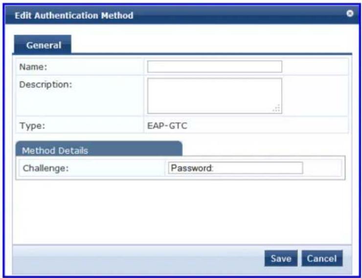
- Specify the EAP-GTC General parameters as described in the following table:
Table 84: EAP-GTC Authentication Method Parameters
| Parameter Action/Description | |
| Name If necessary, specify the name of the authentication method. | |
| Description Optionally, provide the additional information that helps to identify the authentication method. | |
| Type EAP-GTC is preselected. | |
| Method Details | |
| Challenge Optionally, specify a password. |
- Click Save.
EAP-MSCHAPv2
MS-CHAPv2 is an authentication protocol that Microsoft introduced with NT4.0 SP4 and Windows 98. The inner authentication protocol is Microsoft's CHAP (Challenge Handshake Authentication Protocol), meaning allows authentication to databases that support the MS-CHAPv2 format, including Microsoft NT and MicroActive Directory.
To add the EAP-MSCHAPv2 authentication method to W-ClearPass:
- Navigate to Configuration > Authentication > Methods.
The Authentication Methods page opens.
- Select the Add link.
The Add Authentication Method dialog opens:
Figure 155: Adding the EAP-MSCHAPv2 Authentication Method
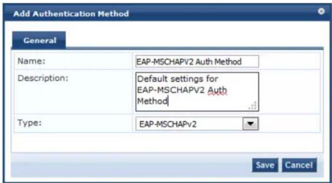
- Specify the EAP-MSCHAPv2 parameters as described in the table below:
Table 85: EAP-MSCHAPv2 Parameters
| Parameter | Description |
| Name Specify | the name of the authentication method. |
| Description | Optionally, provide the additional information that helps to identify the authentication method. |
| Type Select | EAP-MSCHAPv2. |
4. Click Save.
EAP-PEAP
EAP-Protected Extensible Authentication Protocol (EAP-PEAP) is a protocol that creates an encrypted (and secure) channel before the password-based authentication occurs.
PEAP is an 802.1X authentication method that uses server-side public key certificate to establish a secure tunnel in which the client authenticates with server. The PEAP authentication creates an encrypted SSL/TL tunnel between client and authentication server. The exchange of information is encrypted and stored in tunnel ensuring that the user credentials are kept secure.
General Tab
To add the EAP-PEAP authentication method to W-ClearPass:
-
Navigate to Configuration > Authentication > Methods. The Authentication Methods page opens.
-
Select the Add link. The Add Authentication Method dialog opens:
Figure 156: EAP-PEAP - General Tab
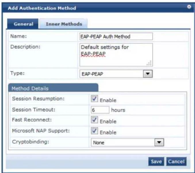
- Specify the EAP-PEAP > General parameters as described in the following table:
Table 86: EAP-PEAP > General Parameters
| Parameter Action/Description | |
| Name Specify the name of the authentication method. | |
| Description Optionally, | provide the additional information that helps to identify the authentication method. |
| Type Select EAP-PEAP. | |
| Method Details | |
| Session Resumption | Check the Session Resumption check box if you intend to enable Fast Reconnect. |
| Session Timeout Caches | EAP-PEAP sessions on the W-ClearPass server for reuse if the user/client reconnects to the W-ClearPass server within the session timeout interval. If session timeout value is set to 0, the cached sessions are not purged. |
| Fast Reconnect Enable | this check box to allow fast reconnect.When Fast Reconnect is enabled, the inner method that takes place inside the server authenticated outer tunnel is also bypassed. This makes the process of reauthentic faster. For Fast Reconnect to work, session resumption must be enabled. |
| Microsoft NAP Support | Check this check box to enable Network Access Protection (NAP) on this W-ClearPa server. |
| Cryptobinding Cryptobinding protects tunnel methods against man-in-the-middle attacks. Cryptographic binding focuses on protecting the server rather than the peer.Specify one of the following cryptobinding options:None (the default)OptionalRequired | |
- Click Save.
Inner Methods Tab
The tunneled method is frequently referred to as the "inner method." The Inner Methods tab controls the inner methods for the EAP-PEAP authentication method.
Figure 157: EAP-PEAP > Inner Methods Tab
 [Aruba EAP GTC] --Select a method-- To set preference for a specific method, use Default button Default Remove Save Cancel](/content/2026/05/842116/images/32dc118e8d2f7ddc5d2ca75672a6c0a3a0f0f15278711616fe1f31f7d4d2a683.jpg)
In FIPS mode, the EAP-MD5 authentication method is not supported.
Specify the EAP-PEAP Inner Methods parameters as described in the following table:
Table 87: EAP-PEAP Inner Methods Tab Parameters
| Parameter Description | |
| Specify inner authentication methods in the preferred order | To append an inner method to the displayed list, select it from the Select a method drop-down list. The list can contain multiple inner methods, which W-ClearPass sends in priority order until negotiation succeeds.Select any method available in the current context from the drop-down list. Inner methods available include:Dell EAP-GTCEAP-GTCEAP-MD5EAP-MSCHAPv2EAP-PWDEAP-TLS with OSCP enabledEAP-TLS |
| Default To set an inner method as the default (the method tried first), select it and click Default. | |
| Remove To remove an inner method from the displayed list, select the method and click Remove. | |
EAP-PEAP-Public
The EAP-PEAP-Public method is used for authenticating and providing a secured wireless guest access to the endpoints. To provide a secured wireless guest access, the Wi-Fi Protected Access (WPA) is provided for known username and password. This ensures that every device gets a unique wireless session key that i

to encrypt the traffic and provide secured wireless access without intruding the privacy of others though same username and password is shared to all devices.
The EAP-PEAP-Public method contains the following two tabs:
• General on page 197
• Inner Methods on page 198
General
The General tab labels the authentication method and defines session details. The following figure is an example of the EAP-PEAP-Public - General tab:
Figure 158: EAP-PEAP-Public - General Tab
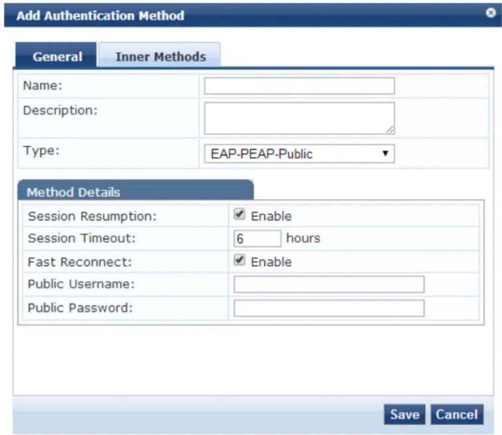
The following table describes the EAP-PEAP-Public - General parameters:
Table 88: EAP-PEAP-Public - General Tab Parameters
| Parameter | Description |
| Name Specify the name of the authentication method. | |
| Description Provide the additional information that helps to identify the authentication method. | |
| Type Specify the type of authentication. In this context, select EAP-PEAP-Public. | |
| Session Resumption | Caches EAP-PEAP-Public sessions on Policy Manager for reuse if the user/client reconnects to Policy Manager within the session timeout interval. By default, this option is enabled. |
| Session Timeout | Caches EAP-PEAP-Public sessions on Policy Manager for reuse if the user/client reconnects to Policy Manager within the session timeout interval in hours. If session timeout value is set to cached sessions are not purged. The default session timeout is 6 hours. |
| Fast Reconnect | Enable this check box to allow fast reconnect. When fast reconnect is enabled, the inner method that happens inside the server authenticated outer tunnel is also bypassed. This makes the best of re-authentication faster. For the fast reconnect to work, session resumption must be enabled. |
| Public Username | Enter the Guest username. In this context, enter 'public'. |
| Public Password | Enter the Guest password. In this context, enter 'public'. |
Inner Methods
The Inner Methods tab controls the inner methods for the EAP-PEAP-Public authentication method. The following figure is an example of the EAP-PEAP-Public - Inner Methods tab:
Figure 159: EAP-PEAP-Public - Inner Methods Tab
 Default Remove --Select a method-- To set preference for a specific method, use Default button Save Cancel](/content/2026/05/842116/images/e4185980d4e09c935a853e45f493521227d89ac076a2b355d8b93c62edceb3d8.jpg)

The EAP-MD5 authentication method is not supported if you use W-ClearPass Policy Manager in the FIPS (Administration > Server Manager > Server Configuration > FIPS tab) mode.
Table 89: EAP-PEAP-Public Inner Methods Tab Parameters
| Parameter Description | |
| Specify inner authentication methods in the preferred order | Select the inner authentication method available from the drop-down list. In context, only the EAP-MSCHAPv2 method is available. The following functions available in this tab:To append an inner method to the displayed list, select it from the drop-list. The list can contain multiple inner methods, which Policy Manager se priority order until negotiation succeeds.To remove an inner method from the displayed list, select the method an Remove.To set an inner method as the default (the method tried first), select it a Default. |
EAP-PWD
EAP-PWD (Password) is an EAP authentication method that uses a shared password for authentication. EAP-PWD addresses the problem of password-based authenticated key exchange using a possibly weak passw for authentication to derive an authenticated and cryptographically strong shared secret.
To add the EAP-PWD authentication method:
- Navigate to Configuration > Authentication > Methods.
The Authentication Methods page opens.
- Select the Add link.
The Add Authentication Method dialog opens:
Figure 160: EAP-PWD Authentication Method Configuration Dialog
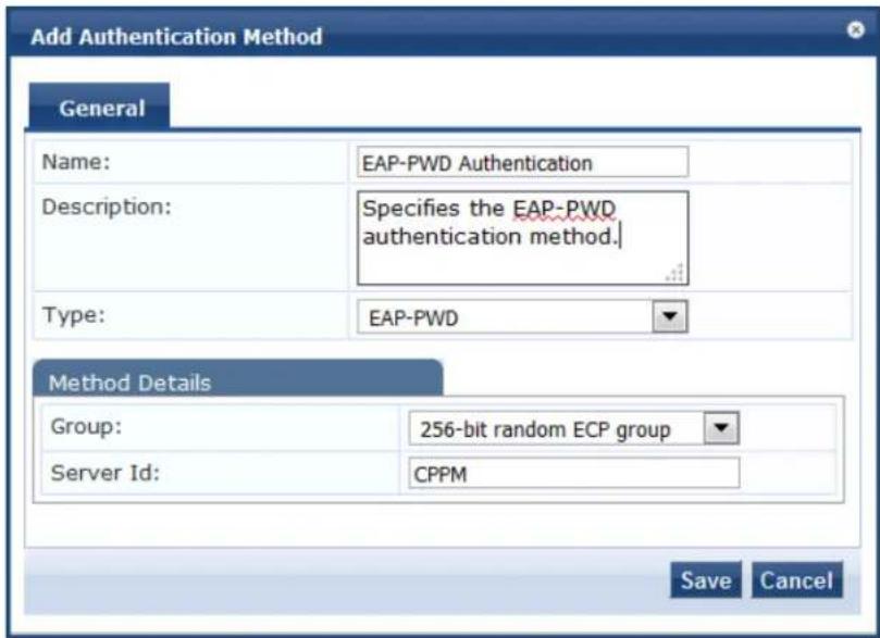
- Specify the EAP-PWD parameters as described in the following table:
Table 90: EAP-PWD Parameters
| Parameter | Description |
| Name Enter | the name of the authentication method. |
| Description | Provide the additional information that helps to identify the authentication method. |
| Type Select | EAP-PWD. |
| Method Details | |
| Group Select | the group from the drop-down list.Each party to the exchange derives ephemeral keys with respect to a particular set of dom parameters that is a group.A group can be based on Finite Field Cryptography (FFC) or Elliptic Curve Cryptography (ECO |
| Server ID | Specify the string that identifies the W-ClearPass server to the peer. |
EAP-TLS
EAP-Transport Layer Security (EAP-TLS) requires an exchange of proof of identities through public key cryptography (such as digital certificates). EAP-TLS secures this exchange with an encrypted TLS tunnel, which helps to resist dictionary or other attacks.
To add the EAP-TLS authentication method:
- Navigate to Configuration > Authentication > Methods.
The Authentication Methods page opens.
- Click Add.
The Add Authentication Method dialog opens.
Figure 161: EAP-TLS Authentication Method Dialog
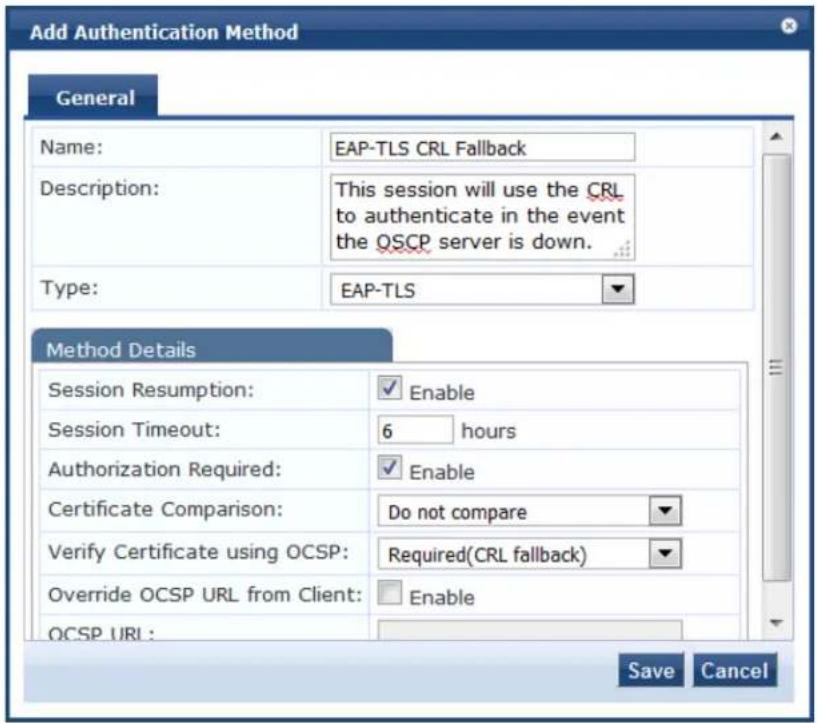
- Specify the Add Authentication Method parameters as described in the following table, then click Save.
Table 91: EAP_TLS Authentication Method Parameters
| Parameter Action/Description | |
| Name Specify the name of the authentication method. | |
| Description Provide the additional information that helps to identify the authentication method (recommended). | |
| Method Details | |
| Type Select EAP_TLS. | |
| Session Resumption Enable this option to cache EAP-TLS sessions on the W-ClearPass server for reuse if the user or client reconnects to the W-ClearPass server within the session timeout interval. This option is enabled by default. | |
| Session Timeout Specify the duration in hours for the cached EAP-TLS sessions to be retained. The default is 6 hours. | |
| Authorization Required This parameter is enabled by default. Specify whether to perform an authorization check. | |
| Certificate Comparison Specify the type of certificate comparison (identity matching) upon presenting Policy Manager with a client certificate:To skip the certificate comparison, choose Do not compare.To compare specific attributes, choose Compare Common Name (CN), Compare Subject Alternate Name (SAN), or Compare CN or SAN.To perform a binary comparison of the stored (in the client record in Active Directory or another LDAP-compliant directory) and presented certificates, choose Compare Binary. | |
| Verify Certificate using OCSP | If the certificate is to be verified by the Online Certificate Status Protocol (OCSP), select Optional or Required.To not verify the certificate, select None.If an OCSP server is not accessible to perform certificate validation, you can the OCSP check and proceed with the CRL validation result by selecting Re (CRL fallback). |
| Override OCSP URL from the Client | Select this option to use a different URL for OCSP.After this option is enabled, you can enter a new URL in the OCSP URL field. |
| OCSP URL | If the Override OCSP URL from the Client field is enabled, enter the replacement URL. |
EAP-TTLS
EAP-Tunneled Transport Layer Security (EAP-TTLS) is designed to provide authentication that is similar to TLS, but each user does not require a certificate be issued. The certificates are issued only to authentic servers.
The EAP-TTLS method contains the following two tabs:
- General Tab on page 203
• Inner Methods Tab on page 204
General Tab
The General tab labels the method and defines session details. The following figure is an example of the EAP-TTLS - General tab:
Figure 162: EAP-TTLS - General Tab
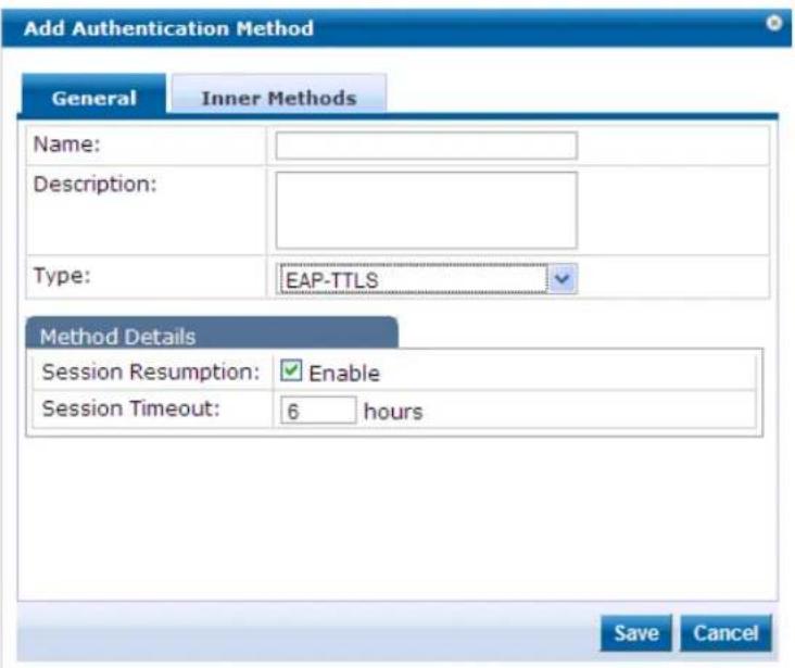
The following table describes the EAP-TTLS - General parameters:
Table 92: EAP-TTLS - General Tab Parameters
| Parameter | Description |
| Name Specify the name of the authentication method. | |
| Description Provide the additional information that helps to identify the authentication method. | |
| Type Select the type of authentication. In this context, select EAP-TTLS.NOTE: The EAP-MD5 authentication type is not supported if you use W-ClearPass Policy Man the FIPS (Administration > Server Manager > Server Configuration > FIPS tab) mode. | |
| Method Details | |
| Session Resumption | Caches EAP-TTLS sessions on Policy Manager for reuse if the user/client reconnects to Policy Manager within the session timeout interval. |
| Session Timeout | Specify the duration in hours for the EAP-TTLS sessions to be cached. |
Inner Methods Tab
The Inner Methods tab controls the inner methods for the EAP-TTLS method. The following figure is an example of the EAP-TTLS - Inner Methods tab:
Figure 163: EAP_TTLS - Inner Methods Tab
![Edit Authentication Method General Inner Methods Specify inner authentication methods in the preferred order: [EAP MSCHAPv2] [EAP TLS] [EAP GTC] [PAP] Select a method... Default Remove To set preference for a specific method, use Default button Save Cancel](/content/2026/05/842116/images/3b7fbd5f4aa7157a14f58b342100b7d1a0eda371874b9b6d3f5643d4fb6f7d8a.jpg)
The following table describes the EAP-TTLS - Inner Methods parameters:
Table 93: EAP-TTLS - Inner Methods Tab Parameters
| Parameter Description | |
| Specify inner authentication methods in the preferred order | Select any method available in the current context from the drop-down list. Functions available in this tab include:To append an inner method to the displayed list, select it from the drop-list. The list can contain multiple inner methods, which Policy Manager se priority order until negotiation succeeds.To remove an inner method from the displayed list, select the method an Remove.To set an inner method as the default (the method that tried first), select click Default.NOTE:The EAP-MD5 authentication type is not supported if you use W-Clear Policy Manager in the FIPS (Administration > Server Manager > Server Configuration > FIPS tab) mode. |
MAC-AUTH Authentication Method
The MAC_AUTH authentication type must be used exclusively in a MAC-based authentication service.
When the MAC_AUTH method is selected, Policy Manager makes internal checks to verify that the request MAC_Authentication request and not a spoofed request. In tunneled EAP methods, authentication and posture credential exchanges occur inside a protected outer tunnel.
The MAC-AUTH method contains the General dialog that labels the authentication method and defines session details. The following figure is an example of the MAC-AUTH > General dialog:
Figure 164: Adding MAC-AUTH Authentication Method
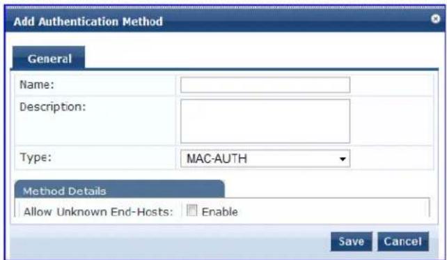
The following table describes the MAC-Auth parameters:
Table 94: MAC-Auth Parameters
| Parameter | Action/Description |
| General | |
| Name Specify the name of the authentication method. | |
| Description Provide the additional information that helps to identify the authentication method (recommend | |
| Type Select the MAC-AUTH type of authentication. | |
| Method Details | |
| Allow Unknown End-Hosts | Select this check box to enable further policy processing of MAC authentication requests of unknown clients.If this is not enabled, Policy Manager automatically rejects a request whose MAC address is configured authentication source. This setting is enabled, for example, when you want Policy Manager to trigger an audit for an unknown client. By selecting this check box and enabling (see Configuring Audit Servers on page 355), you can trigger an audit of an unknown client. |
MSCHAP
The MS-CHAP authentication method authenticates remote Windows-based workstations, integrating the functionality to which LAN-based users are accustomed with the hashing algorithms used on Windows networks. MS-CHAP uses a challenge-response mechanism to authenticate connections without sending an passwords. The MSCHAP method contains the General tab that labels the authentication method and defines session details.
The following figure is an example of the MSCHAP - General tab:
Figure 165: MSCHAP - General Tab
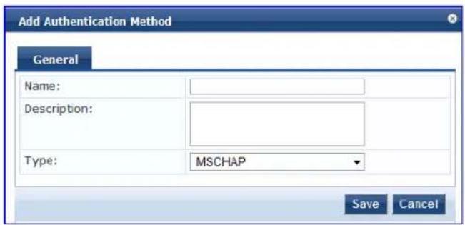
The following table describes the MSCHAP - General parameters:
Table 95: MSCHAP - General Tab Parameters
| Parameter Description | |
| Name Specify the name of the authentication method. | |
| Description Provide the additional information that helps to identify the authentication method. | |
| Type | Select the type of authentication. In this context, select MSCHAP. |
PAP
The Password Authentication Protocol (PAP) is an authentication protocol in which the user name and password are sent to the remote access server in unencrypted form.
The Add Authentication Method dialog identifies the authentication method—in this example, PAP—and defines the method details.
displays the Add Authentication Method > PAP dialog.
Figure 166: Adding the PAP Authentication Method
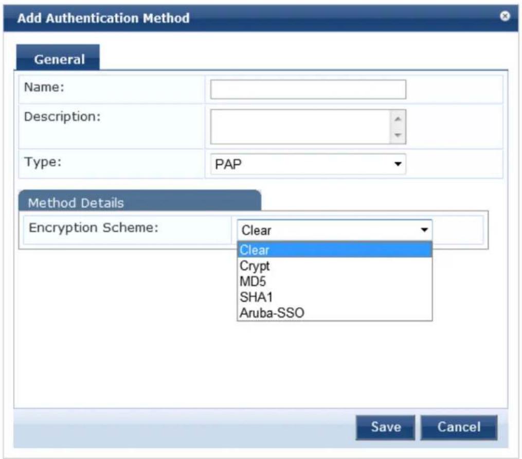
Table 96 describes the PAP parameters:
Table 96: PAP Authentication Method Parameters
| Parameter Action/Description | |
| Name 1. Specify the name of the authentication method. | |
| Description 2. Provide the additional information that helps to identify the authentication method. | |
| Type 3. Select PAP as the Type of authentication. | |
| Method Details | |
| Enable Aruba-SSO | 4. Enable or disable Aruba-SSO (Single Sign-On) by specifying True or False. The default is False. |
Adding and Configuring Authentication Sources
To configure an authentication source for a new service:
- Navigate to Configuration > Authentication > Sources.
Figure 167: Authentication Sources Page
![Configuration → Authentication → Sources Authentication Sources Filter: Name ▼ contains ▼ Go Clear Filter Show 10 records Name ▲ Type Description 1. [Admin User Repository] Local SQL DB Authenticate users against Policy Manager admin user database 2. avenda313 Active Directory 3. [Blacklist User Repository] Local SQL DB Blacklist database with users who have exceeded bandwidth or session related limits 4. [Endpoints Repository] Local SQL DB Authenticate endpoints against Policy Manager local database 5. [Guest Device Repository] Local SQL DB Authenticate guest devices against Policy Manager local database 6. [Guest User Repository] Local SQL DB Authenticate guest users against Policy Manager local database 7. [Insight Repository] Local SQL DB Insight database with session information for users and devices 8. [Local User Repository] Local SQL DB Authenticate users against Policy Manager local user database 9. [Onboard Devices Repository] Local SQL DB Authenticate Onboard devices against Policy Manager local database 10. [Social Login Repository] Local SQL DB Authenticate users against Policy Manager social login database Showing 1-10 of 11 ▶ Copy Export Delete](/content/2026/05/842116/images/c8008b3b4f6363b5587ccde19b37df4a5d5b693247a56503a650cdd32aaf2397.jpg)
2. Click Add.
The Add Authentication Sources page opens. Different tabs and fields appear, depending on the authentication source selected.
Figure 168: Add Authentication Source Page
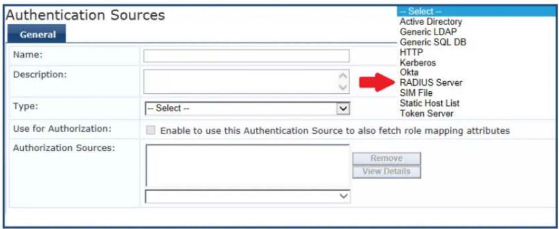
Refer to the following sections to configure these authentication sources:
- Generic LDAP and Active Directory
- Generic SQL DB
- HTTP
- Kerberos
Okta
• RADIUS Server - Adding a Static Host List as an Authentication Source
- Token Server
Generic LDAP and Active Directory
This section includes the following information:
• General Configuration on page 209
• Primary Server Configuration on page 211
• Attributes Configuration on page 213
• Summary Information on page 221
Policy Manager can perform NTLM/MSCHAPv2, PAP/GTC, and certificate-based authentications against Microsoft Active Directory and against any LDAP-compliant directory (for example, Novell eDirectory, OpenLDAP, or Sun Directory Server).
Both LDAP and Active Directory-based server configurations are similar. You can retrieve role-mapping attributes by using filters. For configuration details, see Adding and Modifying Role-Mapping Policies on page 275.
Use the following tabs to configure Generic LDAP and Active Directory authentication sources on the > Add page:
General Configuration
To add a new Generic LDAP and Active Directory:
Navigate to Configuration > Authentication > Sources.
The Authentication Sources page opens.
Click Add.
The Add Authentication Sources dialog opens.
Figure 169: Active Directory or Generic LDAP Configuration Dialog
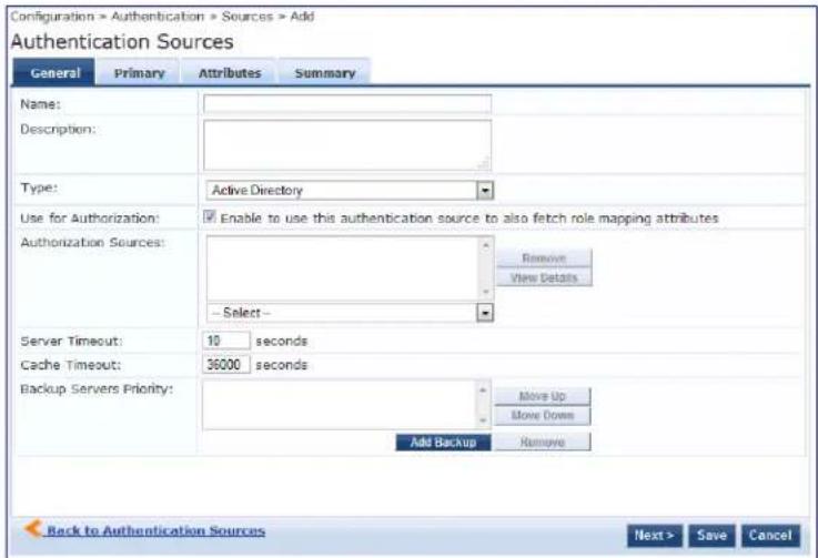
Specify the Generic Active Directory or LDAP > General parameters as described in the following table:
Table 97: Active Directory or GEneric LDAP Authentication Source> General Parameters
| Parameter Action/Description | |
| Name Specify | the name of the authentication source. |
| Description | Provide the additional information that helps to identify the authentication source (recommended) |
| Type Select | Active Directory or Generic LDAP. |
| Parameter | Action/Description |
| Use for Authorization | Enable this check box to instruct Policy Manager to fetch role-mapping attributes (or authorization attributes) from this authentication source. If a user or device successfully authenticates against this authentication source, then Policy Manager also fetches role-mapping attributes from the same source if the Use for Authorization field is enabled. This check box is checked (enabled) by default. |
| Authorization Sources | Specify additional sources from which role-mapping attributes are to be fetched.1. Select a previously configured authentication source from the drop-down list.2. To add the authentication source to the list of authorization sources, click Add.To remove the authentication source from the list, click Remove.If Policy Manager authenticates the user or device from this authentication source, then also fetches role-mapping attributes from these additional authorization sources.NOTE: You can specify additional authorization sources at the service level. Policy Manager fetches role-mapping attributes regardless of which authentication source the user or device was authenticated against. |
| Server Timeout | Specify the duration in number of seconds that Policy Manager waits before considering this server unreachable.If multiple backup servers are available, this value indicates the duration in number of seconds that Policy Manager waits before attempting to fail over from the primary to backup servers in the order in which they are configured. |
| Cache Timeout | Specify the duration in number of seconds for which the attributes are cached.Policy Manager caches attributes fetched for an authenticating entity. |
| Backup Servers Priority | To add a backup server, click Add Backup.When the Backup 1 tab appears, you can specify connection details for a backup server.To remove a backup server, select the server name and click Remove.To change the server priority of the backup servers, select a server, then select Move Up or Move Down.This is the order in which Policy Manager attempts to connect to the backup servers if the primary server is unreachable. |
Primary Server Configuration
The Primary tab defines the settings for the primary server. The following figure is an example of the Generic Active Directory > Primary tab:
Figure 170: Generic LDAP or Active Directory > Primary Tab
Configuration » Authentication » Sources » Add Authentication Sources
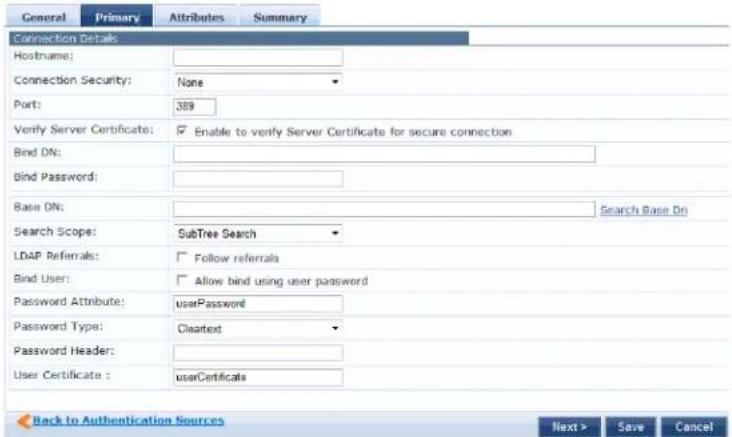
Specify the Active Directory or Generic LDAP > Primary parameters as described in the following table:
Table 98: Active Directory or Generic LDAP > Primary Parameters
| Parameter Action/Description | |
| Hostname Specify the hostname or the IP address of the LDAP or Active Directory server. | |
| Connection Security | For a default nonsecure connection (usually port 389), select None.For a secure connection that is negotiated over the standard LDAP port, select StartTLS. This is the preferred way to connect to an LDAP directory securely.To choose the legacy way of securely connecting to an LDAP directory, select LDAP over SSL or AD over SSL. You must use port 636 for this type of connection. |
| Port Specify the TCP port | at which the LDAP or Active Directory server is listening for connections.The default TCP port for LDAP connections is 389 and the default port for LDAP over SSL is 636. |
| Verify Server Certificate Select this check box to verify the server certificate as part of authentication. | |
| Bind DN | Specify the DN (Distinguished Name) of the administrator account. Policy Manager uses this account to access all other records in the directory.NOTE: For Active Directory, the bind DN can also be in the administrator@domain format (for example, administrator@acme.com). |
| Bind Password | Specify the password for the administrator DN entered in the Bind DN field. |
| NetBIOS Domain Name | Specify the Active Directory domain name for this server. Policy Manager prepends this name to the user ID to authenticate users found in this Active Directory.NOTE: This setting is available only for Active Directory. |
| Base DN Enter the DN (Distinguished Name) of the node in your directory tree from which to start searching for records.1. After entering the values for the fields described above, click Search Base DN to browse the directory hierarchy.The LDAP browser opens. You can navigate to the DN that you want to use as the base DN.2. Click on any node in the tree structure that is displayed to select it as a base DN.Note that the base DN is displayed at the top of the LDAP browser.NOTE: This is also a method to test the connectivity to your LDAP or AD directory. If the values entered for the primary server attributes are correct, you can browse the directory hierarchy by clicking Search Base Dn. | |
| Search Scope Select the scope of the search you want to perform, starting at the base DN.Base Object Search allows you to search at the level specified by the base DN.One Level Search allows you to search up to one level lesser to the immediate children of the base DN.Subtree Search allows you to search the entire subtree under the base DN (including at the base DN level). | |
| LDAP Referral | Enable this check box to automatically follow referrals returned by your directory server in search results. Refer to your directory documentation for more information on referrals. |
| Bind User | Enable this check box to authenticate users by performing a bind operation on the directory using the credentials (user name and password) obtained during authentication.For clients to be authenticated by using the LDAP bind method, Policy Manager must receive the password in clear text. |
| Password Attribute | Enter the name of the attribute in the user record from which user password can be retrieved.NOTE: This is available only for Generic LDAP and is not available for Active Directory. |
| Password Type | Specify whether the password type is Cleartext, NT Hash, or LM Hash.NOTE: This is available only for Generic LDAP. |
| Password Header Specify | Oracle's LDAP implementation that prepends a header to a hashed password string. If using Oracle LDAP, enter the header in this field to correctly identify and read the password.NOTE: This is available only for Generic LDAP and is not available for Active Directory. |
| User Certificate Enter the | name of the attribute in the user record from which user certificate can be retrieved. |
| Always use NetBIOS name | Check this option to always use the NetBIOS name instead of the domain part in the username for authentication.NOTE: This field is available only if you select Active Directory as an authentication source. |
Attributes Configuration
The Attributes tab defines the Active Directory or LDAP Directory query filters and the attributes to be fetched by using those filters.
The following figures are the examples of the Active Directory > Attributes tab and the Generic LDAP Directory > Attributes tab:
Figure 171: Active Directory Attributes Dialog
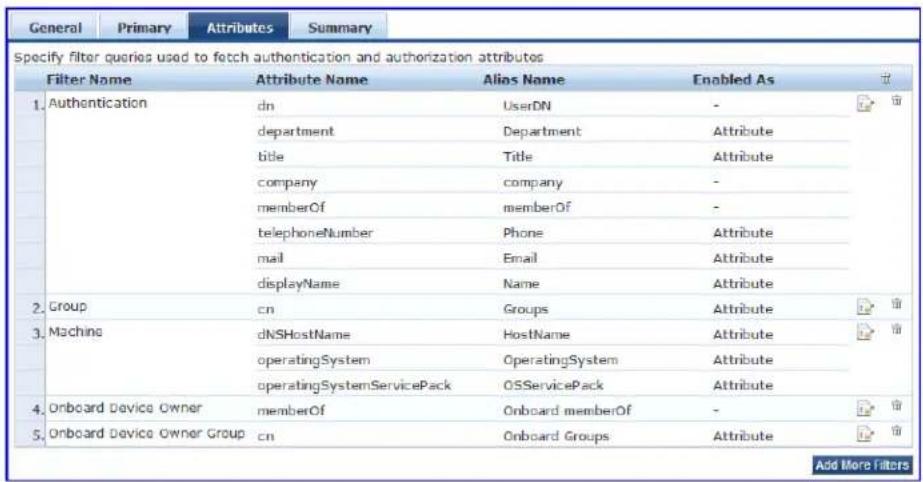
Figure 172: Generic LDAP Directory > Attributes Dialog
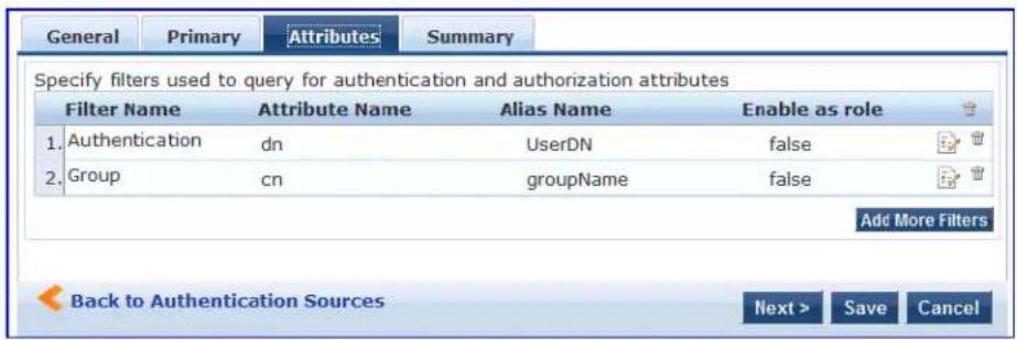
Specify the Active Directory or LDAP Attributes > Filter Listing Screen parameters as described in the following table:
Table 99: Active Directory or Generic LDAP Attributes > Filter Listing Parameters
| Parameter Action/Description | |
| Filter Name Specify the name of the filter. | |
| Attribute Name Specify the name of the LDAP or Active Directory attributes defined for this filter. | |
| Alias Name Specify the alias name for each attribute name selected for the filter. | |
| Enable As Specify whether this value to be used directly as a role or attribute in an enforcement policy.This bypasses the step to assign a role in Policy Manager through a role-mapping policy |
The following table describes the available directories:
Table 100: Active Directory/Generic LDAP Default Filters
| Directory Default Filters | |
| Active Directory | Authentication: This filter is used for authentication. The query searches in the objectClass of the type user. This query finds both user and machine accounts in Active Directory:(& (objectClass=user) (SAMAccountName=%{Authentication:Username}) )After a request arrives, Policy Manager populates %{Authentication:Username} with the authenticating user or machine. This filter is also configured to fetch the following attributes based on this filter query:dn (alias of UserDN): This is an internal attribute that is populated with the user or machine record's DNdepartmenttitlecompany memberOf: In Active Directory, this attribute is populated with the groups that the user or machine belongs to. This is a multi-valued attribute.telephoneNumbermaildisplayNameaccountExpiresGroup: This is a filter used for retrieving the name of the groups a user or machine belongs to.(distinguishedName=%{ memberOf })This query fetches all group records, where the distinguished name is the value returned by thememberOfvariable. The values for thememberOfattribute are fetched by the first filter (authentication) described above. The attribute fetched with this filter query is cn, which is the name of the group. |
| Machine: This query fetches the machine record in Active Directory.(& (objectClass=computer) (SAMAccountName=%{Host:Name} $ ))%{Host:Name} is populated by Policy Manager with the name of the connecting available. dNSHostName, operatingSystem, and operatingSystemServicePack attributes are fetched with this filter query.Onboard Device Owner: This is the filter for retrieving the name of the owner the onboard device belongs to. This query finds the user in the Active Directory (& (SAMAccountName=%{Onboard:Owner}) (objectClass=user))%{Onboard:Owner} is populated by Policy Manager with the name of the onboarded user.Onboard Device Owner Group: This filter is used for retrieving the name of the group the onboarded device owner belongs to.(distinguishedName=%{Onboard memberOf})This query fetches all group records where the DN is the value returned by the Onboard memberOfvariable. The attribute fetched with this filter query is cn, which is the name of the Onboard group. | |
| Generic LDAP Directory | Authentication: This is the filter used for authentication.(& (objectClass=*) (uid=%{Authentication:Username}))When a request arrives, Policy Manager populates %{Authentication:Username} with the authenticating user or machine. This filter is also set up to fetch the following attributes based on this filter query:dn (aliased to UserDN): This is an internal attribute that is populated with the user record's DN.Group: This is the filter used for retrieving the name of the groups to which a user belongs.(&(objectClass=groupOfNames) (member={UserDn}))This query fetches all group records (of objectClass groupOfNames), where the member field contains the DN of the user record (UserDN, which is populated after the authentication filter query is executed. The attribute fetched with this filter query is cn, which is the name of the group (this is aliased to a more readable name: groupName)). |
| Add More Filters | Click this button to open the Authentication Sources > Add page to open the Configure Filter page. From this page, you can define a filter query and the related attributes to be fetched. |
Browse Configuration
The Browse tab shows an LDAP browser from which you can browse the nodes in the LDAP or Active Directory directory, starting at the base DN. This is presented in the read-only mode.
Selecting a leaf node (a node that has no children) displays the attributes associated with that node.
The following figure is an example of the Active Directory or Generic LDAP Configure Filter > Browse dialog:
Figure 173: Active Directory or Generic LDAP Configure Filter > Browse Dialog
![Configure Filter Browse Filter Attributes Configuration Find Node: CN=Alice W.CN=Users.DI=DX-axandays.DI=CC Go CN=Computers CN=ADMIN-PC2 CN=atlas CN=AV-NPS64 CN=AV-TESTLAB-XP DU=Domain Controllers CN=ForeignSecurityPrincipals CN=Infrastructure CN=LostAndFound CN=NTDS Quotas CN=Program Data CN=Microsoft CN=System CN=Users CN=_vmware_ CN=_vmware_user_ CN=Administrator CN=Alice W primaryGroupID 513 pwdLastSet 128746230430312500 sAMAccountName alice sAMAccountType 805306368 sn W title Co-ordinator uSNChanged 234698 uSNCreated 13973 userAccountControl 512 userCertificate [B@7ba83821] userParameters m: d userPrincipalName alice@us.avendays.com whenChanged 20081224201043.0Z whenCreated 20070405181039.0Z Save Close](/content/2026/05/842116/images/9f5c6f514910ad3d234e0c754b6a13b6039fe9eea39188eb06313186d3971140.jpg)
Specify the Active Directory or Generic LDAP Configure Filter Page > Browse tab parameter as described in the following table:
Table 101: Active Directory or Generic LDAP Configure Filter Page > Browse Tab Parameter
| Navigation Action/Description |
| Find Node To find the node, enter the DN, then click the Go button. |
Filter Configuration
The Filter tab provides an LDAP browser interface to define the filter search query.
The following figure is an example of the Active Directory or Generic LDAP Create Filter Page > Filter configuration dialog:
Figure 174: Active Directory or Generic LDAP Create Filter Page > Filter Dialog
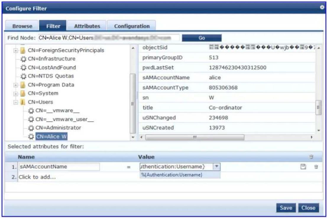

Policy Manager is preconfigured with filters and selected attributes for Active Directory and generic LDAP directory. Create new filters only if you need Policy Manager to fetch role-mapping attributes from a new type of record.

You can fetch different types of records by specifying multiple filters that use different dynamic session attributes. For example, Policy Manager can fetch the user record associated with %{Authentication:Username} and a machine record associated with %{RADIUS:IETF:Calling-Station-ID} for a given request.
The following table describes the Configure Filter Page > Filter tab parameters:
Table 102: Configure Filter Page > Filter Tab Parameters
| Parameter Action/Description | |
| Find Node To find a node, enter the DN, then click the Go button. | |
| Select the attributes for filter | This table has a Name and Value column. You can enter the attribute name in t following two ways:By selecting a node, inspecting the attributes, and then manually entering the attribute name by clicking on Click to add... in the table row.By selecting an attribute on the right hand side of the LDAP browser. The att name and value are automatically populated in the table.The attribute value can be a value that is automatically populated by selecting an attribute from the browser, or it can be manually populated. To aid in populating value with dynamic session attribute values, a drop-down with the commonly use namespace and attribute names is presented. |
Creating Filters
The goal of filter creation is to help Policy Manager find a user or device connecting to the network in Active Directory. To create a filter:
- From the Filter tab, click on a node that you want to extract user or device information from.
For example, browse the Users container in Active Directory and select the node for a user (Alice, for example). On the right hand side, you can view the attributes associated with that user.
- Select the attributes that help Policy Manager identify the user or device.
For example, in Active Directory, an attribute called sAMAccountName stores the user ID.
The attributes that you select are automatically populated in the Filter table displayed below the browser section with their values.
In this example, if you select sAMAccountName, the row in the Filter table shows this attribute with a value of Alice (assuming you picked Alice's record as a sample user node).
After Step 2, you can have values for a specific record (in this example, Alice's record).
- Change the value to a dynamic session attribute that helps Policy Manager associate a session with a specific record in LDAP/Active Directory.
For example, if you selected the sAMAccountName attribute in Active Directory, click the Value field and select %{Authentication:Username}.
When Policy Manager processes an authentication request, %{Authentication:Username} is populated with the user ID of the user connecting to the network.
- Add more attributes from the selected node and continue with Step 2.
Attributes Configuration
The Attributes tab defines the attributes to be fetched from the Active Directory or LDAP directory.
You can also enable each attribute as a role, which means the value fetched for this attribute can be u directly in enforcement policies. For more information, see Configuring Enforcement Policies on page 371.
The following figure displays the Active Directory or Generic LDAP Configure Filter > Attributes tab:
Figure 175: Active Directory or Generic LDAP Configure Filter > Attributes Dialog
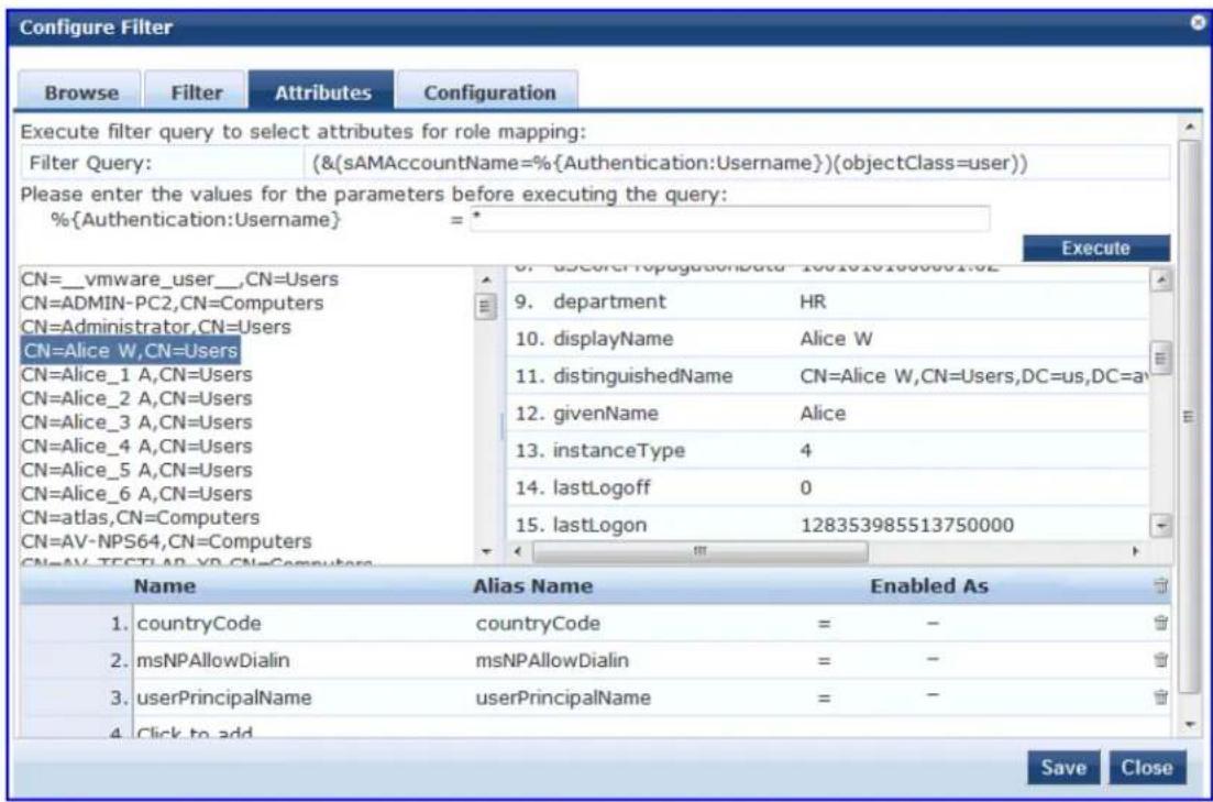
Specify the Active Directory/LDAP Configure Filter Page > Attributes tab parameters as described in the following table:
Table 103: Active Directory/LDAP Configure Filter Page > Attributes Parameters
| Parameter | Action/Description |
| Enter values for parameters | Policy Manager parses the filter query (created in theFiltertab and shown at the top of Attributes tab) and prompts to enter the values for all dynamic session parameters in the query. For example, if you have %{Authentication:Username} in the filter query, you are prompted to enter the value for it. You can enter wildcard character (*) here to match all entries.NOTE: If there are thousands of entries in the directory, entering the wildcard character (*) can take a while to fetch all matching entries. |
| Execute | After entering the values for all dynamic parameters, clickExecuteto execute the filter query.You can see all entries that match the filter query.Click on one of the entries (nodes) to view the list of attributes for that node.Click on the attribute names that you want to use as role mapping attributes. |
| Name Specify | the name of the attribute. |
| Alias Name Specify | specify the alternative name for the attribute. By default, this is the same as the attribute nar |
| Enable As | Click this check box to enable this attribute value to be used directly as a role in an enfor policy. This bypasses the step of assigning a role in Policy Manager through a role-mapping |
Configuration Tab
The Configuration tab shows the filter and attributes configured in the Filter and Attributes tabs respectively. From this tab, you can also manually edit the filter query and the attributes to be fetched. The following figure displays the Configure Filter > Configuration dialog:
Figure 176: Configure Filter > Configuration Dialog
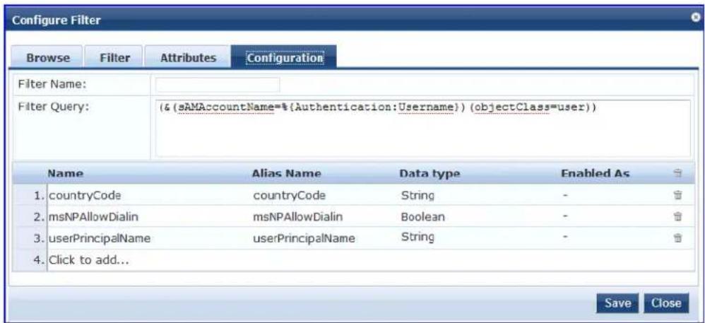
Modify Default Filters
When you add a new authentication source of type Active Directory or LDAP, a few default filters and attributes are populated.
To modify these predefined filters:
- Select a filter on the Authentication > Sources > Attributes dialog. The Configure Filter page for the specified filter opens.
A minimum of one filter must be specified for the LDAP and Active Directory authentication source. This filter is used by Policy Manager to search for the user or device record. If not specified, authentication requests are rejected.

Figure 177: Modify Default Filters > Configuration Dialog
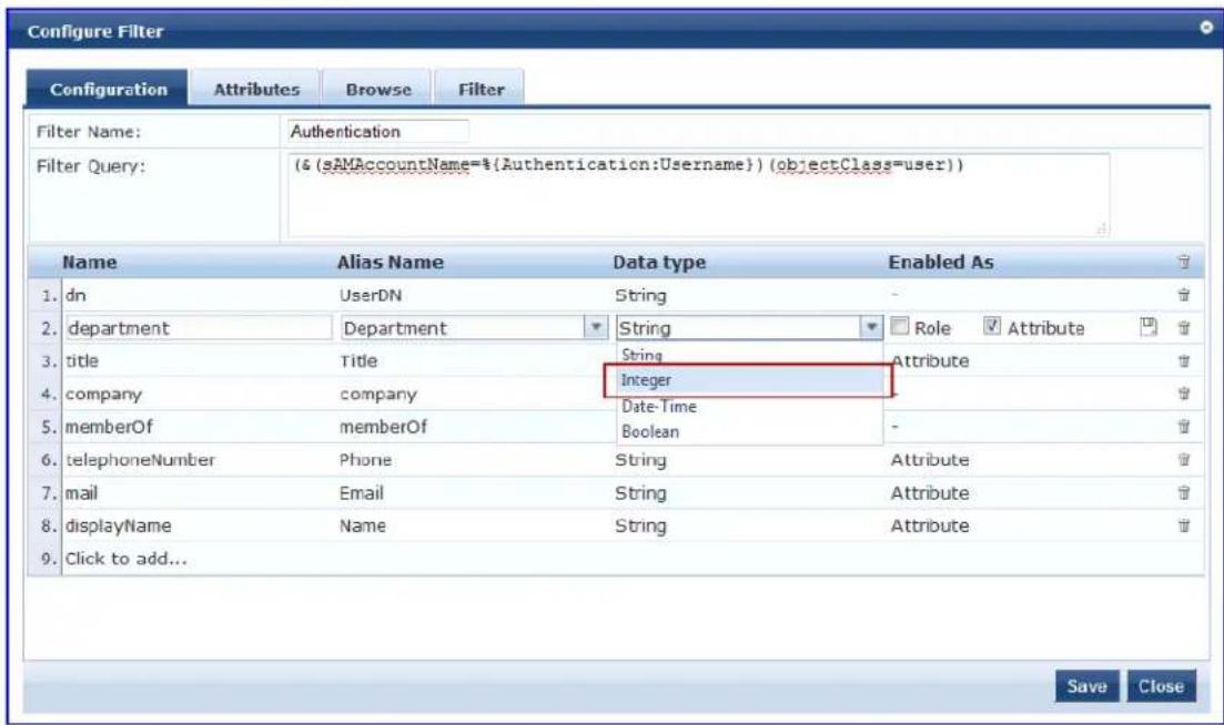
The attributes that are defined for the authentication source display as attributes in role-mapping policy Rules Editor under the authorization source namespace.
-
From the Configure Filter > Configuration dialog, select the attribute you wish to modify.
-
Change the attribute operator values as needed, then click Save.
The operator values that display are based on the Data Type specified here.
For example, if you modify the Active Directory department to be an integer rather than a string, then the list of operator values populate with values that are specific to integers.
Summary Information
You can use the Summary tab to view configured parameters. The following figure is an example of the Active Directory > Summary information:
Figure 178: Active Directory Authentication Source > Summary Information
| Summary | General | Primary | Attributes |
| General: | |||
| Name: | [Blacklist User Repository] | ||
| Description: | blacklist database with users who have exceeded bandwidth or session related limits | ||
| Type: | Local | ||
| Use for Authorization: | Enabled | ||
| Authorization Sources: | - | ||
| Primary: | |||
| Server Name: | localhost | ||
| Port (Optional): | 5432 | ||
| Database Name: | tipodb | ||
| Login Usename: | appuser | ||
| Login Password: | ********** | ||
| Timeout: | 10 | ||
| ODBC Driver: | PostgreSQL | ||
| Attributes: | |||
| Filters : | 1. SELECT 'password' as user_password, CASE WHEN bandwidth_limit_exceed = TRUE THEN 328 WHEN session_duration_exceed = TRUE THEN 329 WHEN session_count_exceed = TRUE THEN 230 END AS Account_Status FROM tips_post_auth_enf_log WHERE user_id = %(Authentication:Username)' order by timestamp desc limit 1 | ||
Generic SQL DB
Configure the primary and backup servers, session details, filter query, and role-mapping attributes to fet Generic SQL authentication sources on the following tabs:
• General Tab on page 222
• Primary Tab on page 224
• Attributes Tab on page 225
• Summary Tab on page 227
W-ClearPass Policy Manager can perform MSCHAPv2 and PAP/GTC authentication against any Open Datab Connectivity (ODBC)-compliant SQL database such as Microsoft SQL Server, Oracle, MySQL, or PostgreSQL.
Specify a stored procedure to query the relevant tables and retrieve role-mapping attributes by using filter
General Tab
Navigate to the Configuration > Authentication > Sources, then click Add.
The General tab labels the authentication source and defines session details, authorization sources, and backup server details.
Figure 179: Add Generic SQL DB > General Tab
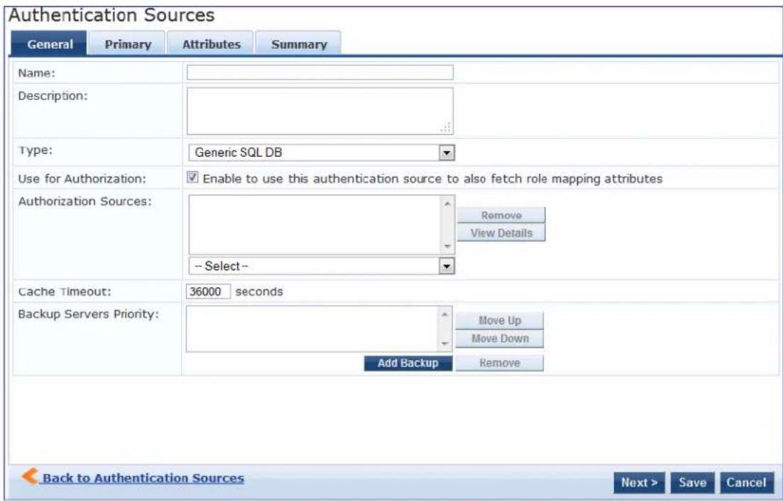
The following table describes the Add General SQL DB > General parameters:
Table 104: Add Generic SQL DB > General Parameters
| Parameter Action/Description | |
| Name Specify | the name of the authentication source. |
| Description Provide the additional information that helps to identify the authentication source. | |
| Type Select Generic SQL DB. | |
| Use for Authorization | Enable this option to request Policy Manager to fetch role-mapping attributes (or authorization attributes) from this authentication source.If a user or device successfully authenticates against this authentication source, then Policy Manager also fetches role-mapping attributes from the same source if the Use for Authorization field is enabled. This check box is enabled by default. |
| Authorization Sources | Specify additional sources from which to fetch role-mapping attributes. Select a previously configured authentication source from the drop-down list and click Add to add to the list of authorization sources.Click Remove to remove the authorization source from the list.If Policy Manager authenticates the user or device from this authentication source, then Policy Manager also fetches role-mapping attributes from these additional authorization sources.NOTE: You can specify additional authorization sources at the service level. Policy Manager fetches role-mapping attributes irrespective of which authentication source the user or device was authenticated against. |
| Backup Servers | To add a backup server, click Add Backup.From the Backup 1 tab, you can specify connection details for a backup server (same fields as for primary server that are specified below).To remove a backup server, select the server name and click Remove.Select Move Up or Move Down to change the server priority of the backup servers. This is the order in which Policy Manager attempts to connect to the backup servers. |
| Cache Timeout | Policy Manager caches attributes fetched for an authenticating entity. This parameter controls the time period for which the attributes are cached. |
Primary Tab
The Primary tab defines the settings for the primary server. The following figure displays the Add General SQL DB > Primary tab:
Figure 180: Add Generic SQL DB > Primary Tab
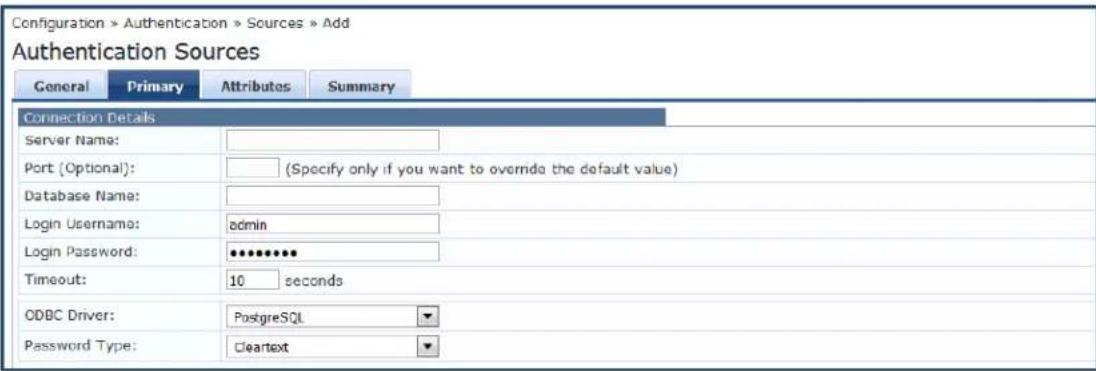
The following table describes the Generic SQL DB > Primary parameters:
Table 105: Generic SQL DB > Primary Tab Parameters
| Parameter | Action/Description |
| Server Name | Enter the hostname or IP address of the database server. |
| Port (Optional) | Specify a port value to override the default port. |
| Database Name | Enter the name of the database from which records can be retrieved. |
| Login Username | Enter the name of the user used to log into the database. This account must have read ad the attributes that need to be retrieved by the specified filters. |
| Password | Enter the password for the user account entered in the Login Username field. |
| Timeout | Enter the duration in seconds that Policy Manager waits before attempting to fail over from primary to backup servers (in the order in which they are configured). |
| ODBC Driver | Select the ODBC (Open Database Connectivity) driver to connect to the database.MySQL is supported in versions 6.0 and later. Dell does not ship MySQL drivers by default. If you require MySQL, contact Dell support at dell.com/support to get the required patch. This patch does not persist across upgrades. If you are using MySQL, you should contact Support before upgrading. If you connect to a Microsoft SQL server using Integrated Authentication, the login username in the authentication source, formatted as either domain/username or UPN (User Principal Name), the following characters are supported:Backslash ( \ )At-sign (@)HyphenUnderscore |
| Password Type | Specify how the user password is stored in the database:Cleartext : Stored as clear, unencrypted text.NT Hash: Stored with an NT hash using MD4.LM Hash : Stored with a LAN Manager Hash using DES.SHA: Stored with a Secure Hash Algorighm (SHA) hash.SHA256: Stored with an SHA-256 hash function. |
Attributes Tab
The Attributes tab defines the SQL DB query filters and the attributes to be fetched by using those filters. The following figure displays the Generic SQL DB > Attributes tab:
Figure 181: Generic SQL DB > Attributes Tab
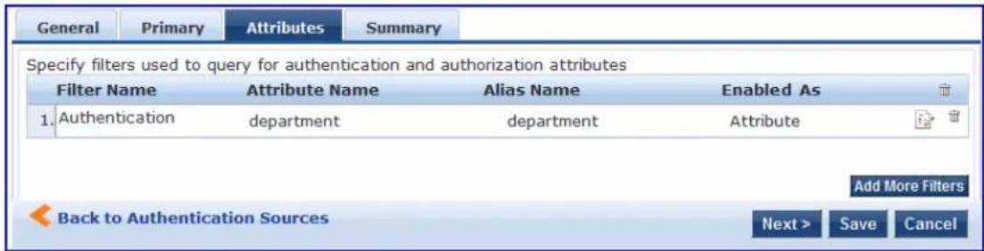
The following table describes the Generic SQL DB > Attributes (Filter List) parameters:
Table 106: Generic SQL DB > Attributes Tab (Filter List) Parameters
| Parameter Action/Description | |
| Filter Name | Specifies the name of the filter. |
| Attribute Name | Specifies the name of the SQL DB attributes defined for this filter. |
| Alias Name | Specifies an alias name for each attribute name selected for the filter. |
| Enabled As Indicates whether the filter is enabled as a role or attribute type. This can also be blank. | |
| Add More Filters | Click this button to open the Configure Filter page.Use this page to define a filter query and the related attributes to be fetched from the store. Figure 182 displays the Generic SQL DB > Configure Filter page. |
Adding More Filters
To add more filter queries and their related attributes:
- Click Add More Filters.
The Configure Filter page opens:
Figure 182: Generic SQL DB > Configure Filter Page
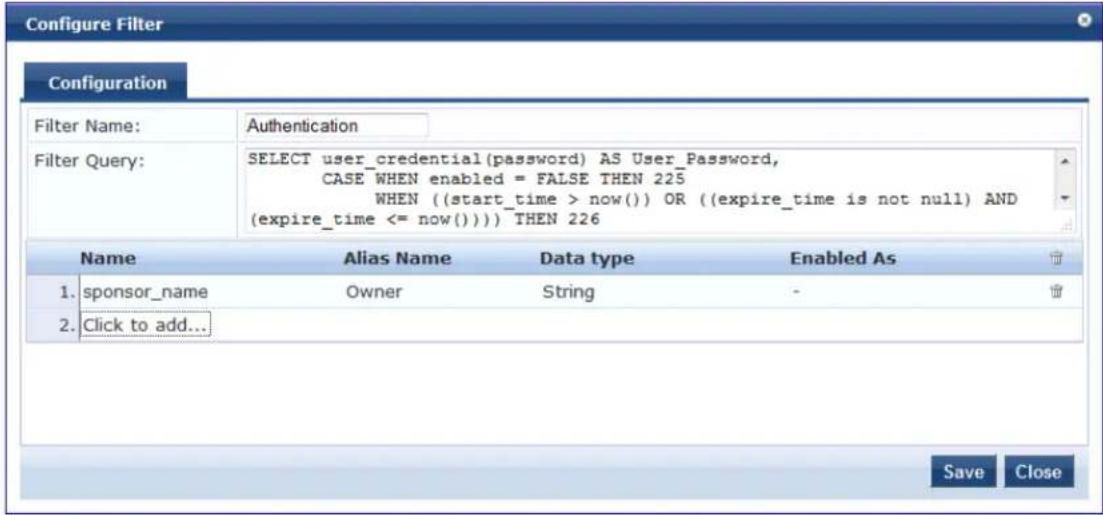
- To add a filter and configure its attributes, select Click to add.
A new row opens. - Specify the Name of the filter, Alias Name, Data Type, and optionally, Enabled As attributes.
- Repeat to add additional filters, then click Save.
- Specify the Add Generic SQL DB > Configure Filter parameters as described in the following table:
Table 107: Add Generic SQL DB > Configure Filter Page Parameters
| Parameter | Action/Description |
| Filter Name | Enter the name of the filter. |
| Filter Query | Specify an SQL query to fetch the attributes from the user or device record in DB. |
| Name | Specify the name of the attribute. |
| Alias Name | Specify the name for the attribute. By default, this is the same as the attribute name. |
| Data Type | Specify the data type for this attribute such as String, Integer, or Boolean. |
| Enabled As | Specify whether this value to be used directly as a role or attribute in an enforcement policy. This bypasses the step of having to assign a role in Policy Manager through a role-mapping policy. |
Summary Tab
Use the Summary tab to view the parameters configured. The following figure displays the Generic SQL DB
Summary tab:
Figure 183: Add Generic SQL DB > Summary Tab
![Configuration > Authentication > Sources > Add Authentication Sources General Primary Attributes Summary General: Name: Test Repository Description: Authenticate users against Policy Manager local user database. Type: Sql Use for Authorization: Enabled Authorization Sources: [Local User Repository] [Local] Primary: Server Name: 10.17.4.200 Port (Optional): 1333 Database Name: Test DB Login Username: admin Login Password: ***** Timeout: 10 ODBC Driver: PostgreSQL Password Type: Cleartext Attributes: Filters : -](/content/2026/05/842116/images/8425186cca1042cc190c6b01f69b6f98127a5e7e6781c284d4137500018511c1.jpg)
HTTP
The HTTP authentication source relies on the GET method to retrieve information. The client submits a r and then the server returns a response. All request parameters are included in the URL. For example, URL:
https://hostname/webservice/.../%{Auth:Username}?param1=%{...}¶m2=value2. HTTP relies on the assumption that the connection between the client and server is secure and can be trusted.
Configure primary and backup servers, session details, filter query, and role mapping attributes to fetch I authentication sources using the following tabs:
• General Tab on page 228
• Primary Tab on page 229
• Attributes Tab on page 230
• Summary Tab on page 232
General Tab
The General tab labels the authentication source and defines session details, authorization sources, and backup server details. The following figure displays the HTTP - General tab:
Figure 184: HTTP - General Tab
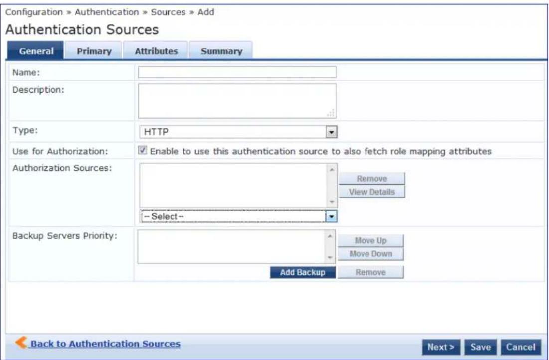
The following table describes the HTTP - General tab parameters:
Table 108: HTTP - General Tab Parameters
| Parameter Description | |
| Name Specify | the name of the authentication source. |
| Description Provide the additional information that helps to identify the authentication source. | |
| Type Select the type of source. In this context, select HTTP. | |
| Parameter | Description |
| Use for Authorization | Enable this option to request Policy Manager to fetch role mapping attributes (or authorization attributes) from this authentication source. If a user or device successfully authenticates against this authentication source, then Policy Manager also fetches role mapping attributes from the same source if the Use for Authorization field is enabled. This check box is enabled by default. |
| Authorization Sources | Specify additional sources from which to fetch role mapping attributes. Select a previously configured authentication source from the drop-down list and click Add to add it to the list of authorization sources. Click Remove to remove the selected additional resource from the list.If Policy Manager authenticates the user or device from this authentication source, then also fetches role mapping attributes from these additional authorization sources.NOTE: You can specify additional authorization sources at the service level. Policy Manager fetches role mapping attributes irrespective of which authentication source the user or device was authenticated against. |
| Backup Servers | To add a backup server, click Add Backup. From the Backup 1 tab, you can specify connection details for a backup server (same fields applicable for primary server specified below). To remove a backup server, select the server name and click Remove. Select Move Up or Move Down to change the server priority of the backup servers. This is the order in which Policy Manager attempts to connect to the backup servers. |
Primary Tab
The Primary tab defines the settings for the primary server. The following figure displays the HTTP - Primary tab:
Figure 185: HTTP - Primary Tab
Configuration » Authentication » Sources » Add
Authentication Sources
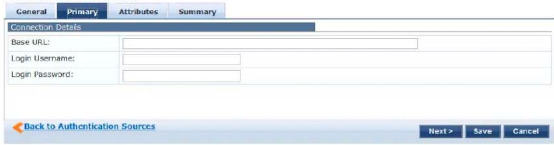
The following table describes the HTTP - Primary tab parameters:
Table 109: HTTP - Primary Tab Parameters
| Parameter | Description |
| Base URL Enter the base URL (host name) or IP address of the HTTP server. For example, http://or:xxxx, where xxxx is the port to access the HTTP Server. | |
| Login Username | Enter the name of the user used to log into the database. This account must have read access to the attributes that need to be retrieved by the specified filters. |
| Password | Enter the password for the user account entered in the Login Username field. |
Attributes Tab
The Attributes tab defines the HTTP query filters and the attributes to be fetched by using those filters.
Figure 186: HTTP - Attributes Tab
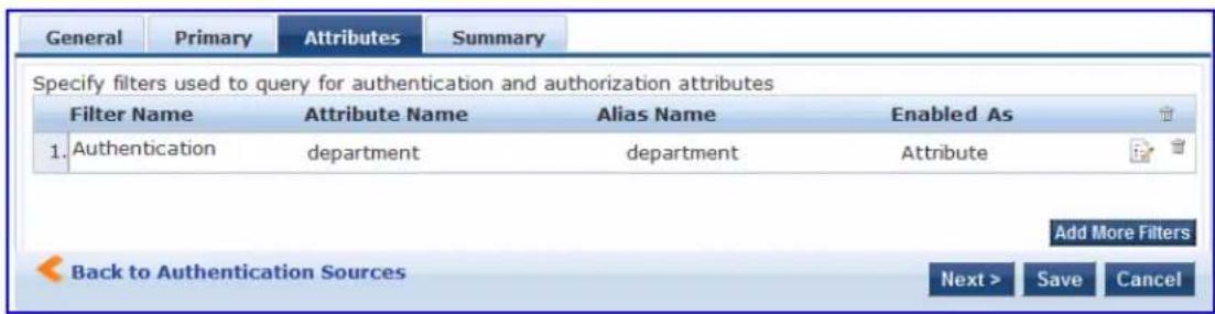
The following table describes the HTTP - Attributes tab parameters:
Table 110: HTTP - Attributes tab (Filter List) Parameters
| Parameter Description | |
| Filter Name Displays the name of the filter. | |
| Attribute Name Specifies the name of the SQL DB attributes defined for this filter. | |
| Alias Name | Specifies the name of an alias name for each attribute name selected for the filter. |
| Enabled As | Indicates whether an attribute is enabled as a role. |
| Add More Filters | Opens the Configure Filter page. For more information, see Add More Filters on page 231. |
Add More Filters
The Configure Filter page defines a filter query and the related attributes to be fetched from the SQL DB store. The following figure displays the HTTP Filter Configure page:
Figure 187: HTTP Filter Configure Page
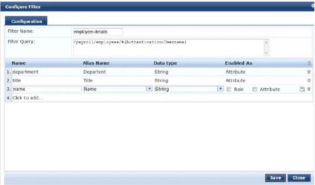
The following table describes the HTTP Configure - Filter parameters:
Table 111: HTTP Configure Filter Page Parameters
| Parameter | Description |
| Filter Name | Displays the name of the selected filter. |
| Filter Query | Specifies the HTTP path (without the server name) to fetch the attributes from the HTTP server. For example, if the full path name to the filter is http server URL = http://:xxxx/abc/def/xyz, you enter /abc/def/xyz. |
| Name Specifies the name of the attribute. | |
| Alias Name | Specifies the alias name for the attribute. By default, this is the same as the attribute name. |
| Data Type Specifies the data type for this attribute such as String, Integer, and Boolean. | |
| Enabled As | Specify whether the value to be used directly as a role or attribute in an enforcement policy. This bypasses the step of assigning a role in Policy Manager through a role mapping policy. |
Summary Tab
You can use the Summary tab to view configured parameters. The following figure is an example of the HTTP - Summary tab:
Figure 188: HTTP - Summary Tab
Configuration • Authentication • Sources • Add
Authentication Sources
| General | Primary | Attributes | Summary |
| General: | |||
| Name: | Test Auth Source | ||
| Description: | Authenticating against the Local OB | ||
| Type: | HTTP | ||
| Use for Authorization: | Enabled | ||
| Authorization Sources: | [Local User Repository] [Local] | ||
| Primary: | |||
| Base URL: | - | ||
| Login Username: | admin | ||
| Login Password: | passwords | ||
| Attributes: | |||
| Filters : | - | ||
Kerberos
Policy Manager can perform standard PAP/GTC or tunneled PAP/GTC (for example, EAP-PEAP[EAP-GTC]) authentication against any Kerberos 5 compliant server such as Microsoft Active Directory server. It is mandatory to pair this source type with an authorization source (identity store) containing user records.
You can configure Kerberos authentication sources using the following tabs:
• General Tab on page 233
• Primary Tab on page 234
• Summary Tab on page 235
General Tab
The General tab labels the authentication source and defines session details, authorization sources, and backup server details. The following figure displays the Kerberos - General tab:
Figure 189: Kerberos - General Tab
Authentication Sources
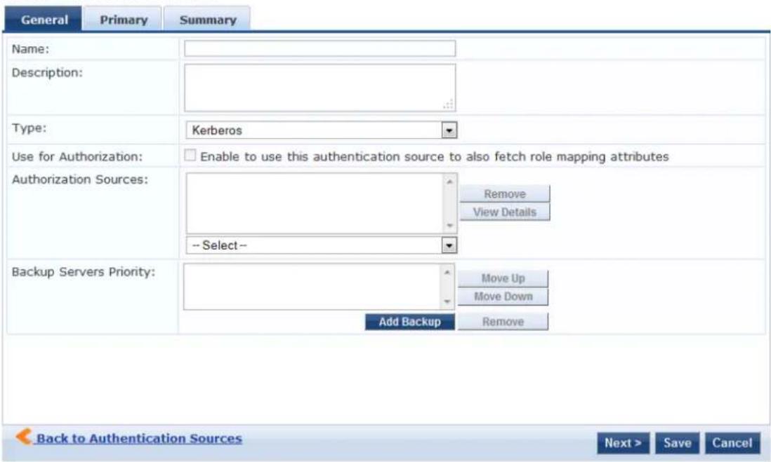
The following table describes the Kerberos - General parameters:
Table 112: Kerberos - General Tab Parameters
| Parameter Description |
| Name Specify the name of the authentication source. |
| Description Provide the additional information that helps to identify the authentication source. |
| Type Select the type of source. In this context, select Kerberos. |
Table 112: Kerberos - General Tab Parameters (Continued)
| Parameter Description | |
| Use for Authorization | Disable in this context. |
| Authorization Sources | Specify one or more authorization sources from which role mapping attributes to be fetched. Select a previously configured authentication source from the drop-down list and click Add to add it to the list of authorization sources. Click Remove to remove the selected authentication source from the list.NOTE: You can specify additional authorization sources at the service level. Policy Manager fetches role mapping attributes irrespective of which authentication source the user or device was authenticated against. |
| Backup Servers | To add a backup kerberos server, click Add Backup. From the Backup 1 tab, you can specify connection details for a backup server (same fields applicable for primary server specified below).To remove a backup server, select the server name and click Remove. Select Move Up or Move Down to change the server priority of the backup servers. This is the order in which Policy Manager attempts to connect to the backup servers. |
Primary Tab
The Primary tab defines the settings for the primary server. The following figure displays the Kerberos - Primary tab:
Figure 190: Kerberos - Primary Tab
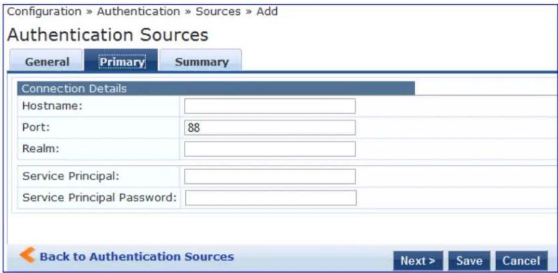
The following table describes the Kerberos - Primary parameters:
Table 113: Kerberos - Primary Tab Parameters
| Parameter Description | |
| Hostname Specify the name of the host or the IP address of the kerberos server. | |
| Port Specify the port at which the token server listens for kerberos connections. The default port is 88. | |
| Realm | Specify the domain of authentication. In the case, specify Kerberos domain. |
| Service Principal Name | Enter the identity of the service principal as configured in the Kerberos server. |
| Service Principal Password | Enter the password for the service principal. |
Summary Tab
You can use the Summary tab to view configured parameters. The following figure displays the Kerberos - Summary tab:
Figure 191: Kerberos - Summary Tab
Configuration > Authentication > Sources > Add Authentication Sources
![General Name: Test Auth Source Description: testing auth source against local DB. Type: Kerberos Use for Authorization: Disabled Authorization Sources: [Local User Repository] [Local] Primary: Hostname: 10.17.4.200 Port: 88 Realm: - Service Principal: admin Service Principal Password: ********](/content/2026/05/842116/images/193b247ab786dfda4db0cf4dcfd076840dc2db2986e5475363721afc82d558c0.jpg)
Okta
You can use Okta as an authentication source only for servers of the type Dell Application Authentication Configure Okta authentication sources on the following tabs:
• General Tab on page 236
• Primary Tab on page 237
• Attributes Tab on page 238
• Summary Tab on page 240
General Tab
The General tab labels the authentication source and defines session details, authorization sources, and backup server details. The following figure is an example of the Okta - General tab:
Figure 192: Okta - General Tab
Authentication Sources
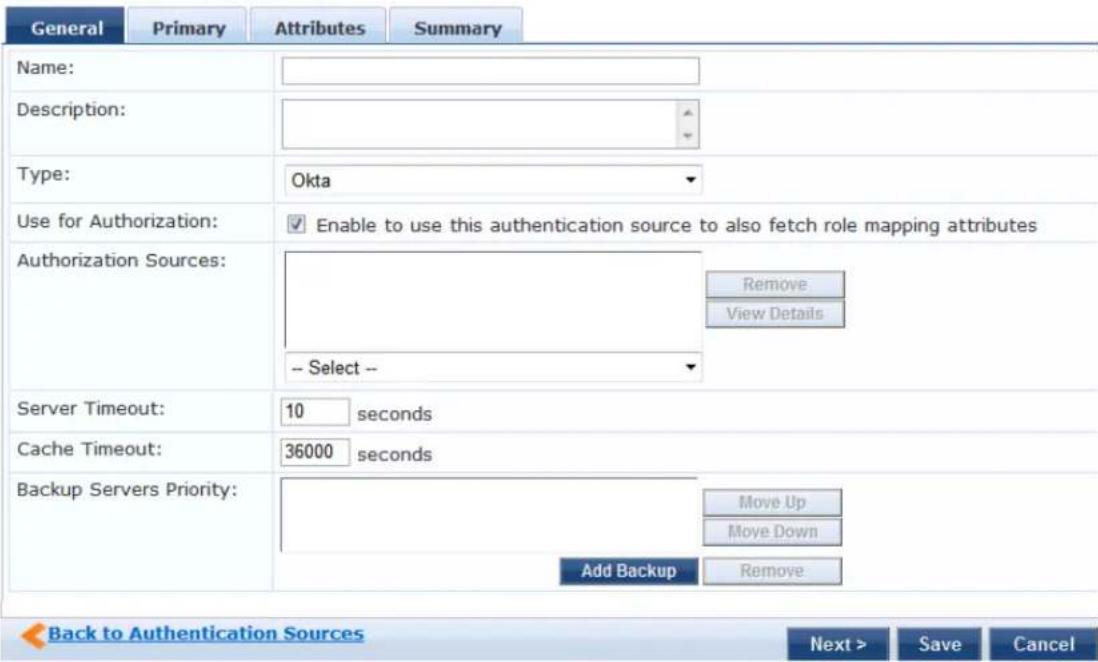
The following table describes the Okta - General parameters:
Table 114: Okta - General Tab Parameters
| Parameter Description | |
| Name Specify the name of the authentication source. | |
| Description Provide the additional information that helps to identify the authentication source. | |
| Type Select the type of source. In this context, select Okta. | |
| Use for Authorization | Enable this check box to request Policy Manager to fetch role mapping attributes (or authorization attributes) from this authentication source. If a user or device successfully authenticates against this authentication source, then Policy Manager also fetches role mapping attributes from the same source if the Use for Authorization field is enabled. This check box is enabled by default. |
| Server Timeout Specify the duration in number of seconds that Policy Manager waits before considering this server unreachable. If multiple backup servers are available, then this value indicates the duration in number of seconds that Policy Manager waits before attempting to fail over from the primary to the backup servers in the order in which they are configured. | |
| Cache Timeout Policy Manager caches attributes fetched for an authenticating entity. This parameter controls the duration in number of seconds for which the attributes are cached. | |
| Backup Servers Priority Click Add Backup to add a backup server. From the Backup 1 tab, you can specify connection details for a backup server (same fields as for primary server that are specified below). To remove a backup server, select the server name and click Remove. Select Move Up or Move Down to change the server priority of the backup servers. This is the order in which Policy Manager attempts to connect to the backup servers. | |
Primary Tab
The Primary tab defines the settings for the primary server. The following figure displays the Okta - Primary tab:
Figure 193: Okta - Primary Tab
Authentication Sources
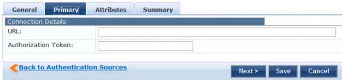
The following table describes the Okta - Primary parameters:
Table 115: Okta - Primary Tab Parameters
| Parameter Description | |
| Connection Details | |
| URL Enter the address of the | Okta server. |
| Authorization Token Enter the | authorization token provided by Okta support. |
Attributes Tab
The Attributes tab defines the Okta query filters and the attributes to be fetched by using those filters. The following figure displays the Okta - Attributes tab:
Figure 194: Okta - Attributes Tab
Authentication Sources
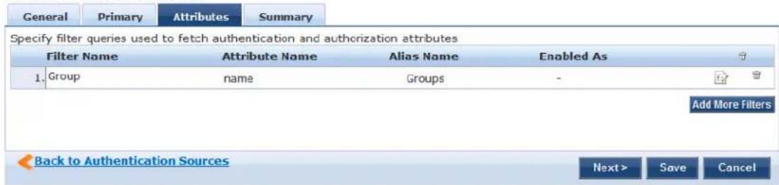
The following table describes the Okta - Attributes parameters:
Table 116: Okta - Attributes Tab Parameters
| Parameter Description | |
| Filter Name Displays the name of the filter.You can configure only Group for Okta. | |
| Attribute Name Specifies the name of the LDAP/AD attributes defined for this filter. | |
| Alias Name Specifies the alias name for each attribute name selected for the filter. | |
| Enable As Specifies whether value to be used directly as a role or attribute in an enforcement policy. This bypasses the step of assigning a role in Policy Manager through a role mapping policy. | |
| Add More Filters | Click this button to open the Configure Filter page. Refer to Add More Filters on page 239. |
Add More Filters
The Configure Filter page defines a filter query and the related attributes to be fetched from the SQL DB store. The following figure displays the Okta - Configure Filter page:
Figure 195: Okta - Configure Filter Page
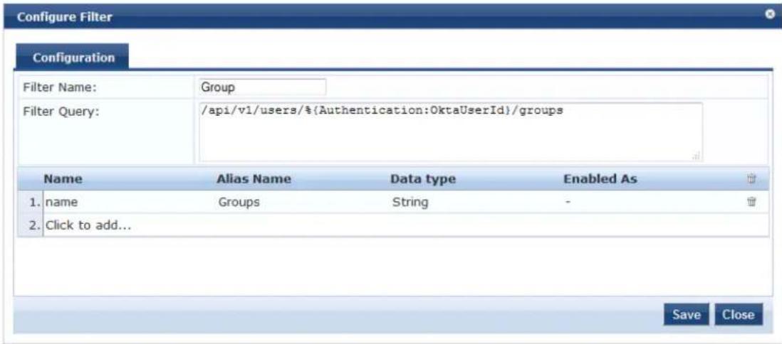
The following table describes the Okta Configure Filter parameters:
Table 117: Okta Configure Filter Page
| Parameter | Description |
| Filter Name | Enter the name of the filter. |
| Filter Query | Specifies an SQL query to fetch attributes from the user or device record in DB. |
| Name Displays the name of the attribute. | |
| Alias Name | Specifies an alias name for the attribute. By default, this is the same as the attribute name. |
| Data Type | Specifies the data type for this attribute such as String, Integer, and Boolean. |
| Enabled As | Specify whether this value is to be used directly as a role or attribute in an enforcement policy bypasses the step of having to assign a role in Policy Manager through a role mapping policy. |
Summary Tab
You can use the Summary tab to view configured parameters. The following figure displays the Okta - Summary tab:
Figure 196: Okta - Summary Tab
Configuration » Authentication » Sources » Add
Authentication Sources
| General Primary Attributes Summary | |
| General: | |
| Name: | Test Auth Source |
| Descriptions: | Authenticating against the Local DB. |
| Type: | Okta |
| Use for Authorization: | Enabled |
| Authorization Sources: | [Local User Repository] [Local] |
| Primary: | |
| URL: | - |
| Authorization Token: | ***** |
| Attributes: | |
| Filters : | 1. /api/v1/users/%(Authentication:OktaUserId)/groups |
RADIUS Server
You can use the RADIUS Server as an authentication source to allow W-ClearPass to query a third-party RADIUS Server for authentication. Configure RADIUS Server authentication sources on the following tabs:
• General Tab on page 240
• Primary Tab on page 241
• Attributes Tab on page 242
• Summary Tab on page 243
General Tab
The General tab labels the authentication source and defines session details, authorization sources, and backup server details. The following figure displays the RADIUS Server - General tab:
Figure 197: RADIUS Server - General Tab
Authentication Sources
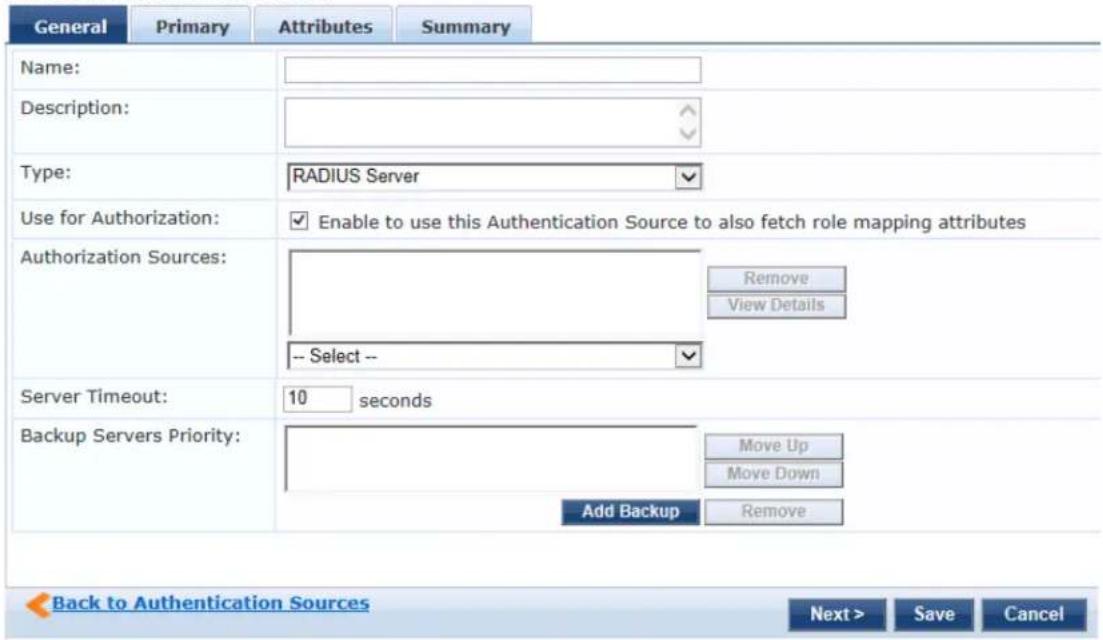
The following table describes the Radius Server - General parameters:
Table 118: Radius Server - General Tab Parameters
| Parameter Description | |
| Name Specify the | name of the authentication source. |
| Description Provide | the additional information that helps to identify the authentication source. |
| Type Select the type of source. In this context, select RADIUS Server. | |
| Use for Authorization | Enable this check box to request Policy Manager to fetch role mapping attributes (or authorization attributes) from this authentication source. If a user or device successfully authenticates against this authentication source, then Policy Manager also fetches role mapping attributes from the same source if the Use for Authorization field is enabled. This check box is enabled by default. |
| Server Timeout | Specify the duration in number of seconds that Policy Manager waits before considering this server unreachable. If multiple backup servers are available, then this value indicates the duration in number of seconds that Policy Manager waits before attempting to fail over from the primary to the backup servers in the order in which they are configured. |
| Backup Servers Priority | Click Add Backup to add a backup server. From the Backup 1 tab, you can specify connection details for a backup server (same fields as for primary server that are specified below). To remove a backup server, select the server name and click Remove. Select Move Up or Move Down to change the server priority of the backup servers. This is the order in which Policy Manager attempts to connect to the backup servers. |
Primary Tab
The Primary tab defines the settings for the primary server. The following figure displays the RADIUS Server - Primary tab:
Figure 198: RADIUS Server - Primary Tab
Authentication Sources
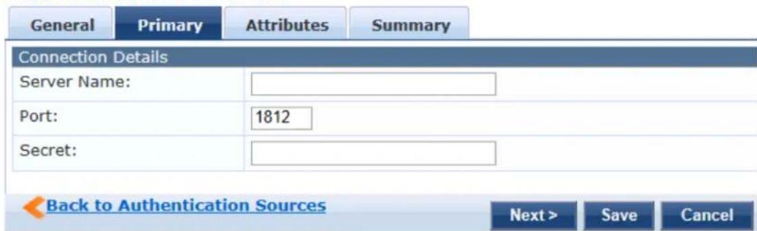
The following table describes the Radius Server - Primary parameters:
Table 119: RADIUS Server - Primary Tab Parameters
| Parameter Description | |
| Connection Details | |
| Server Names Enter the name of the RADIUS Server. | |
| Port The default | port number is 1812. You may enter a different port number if required. |
| Secret Enter the secret key for authentication. | |
Attributes Tab
The Attributes tab defines the Okta query filters and the attributes to be fetched by using those filters. The following figure displays the RADIUS Server - Attributes tab:
Figure 199: RADIUS Server - Attributes Tab
Authentication Sources
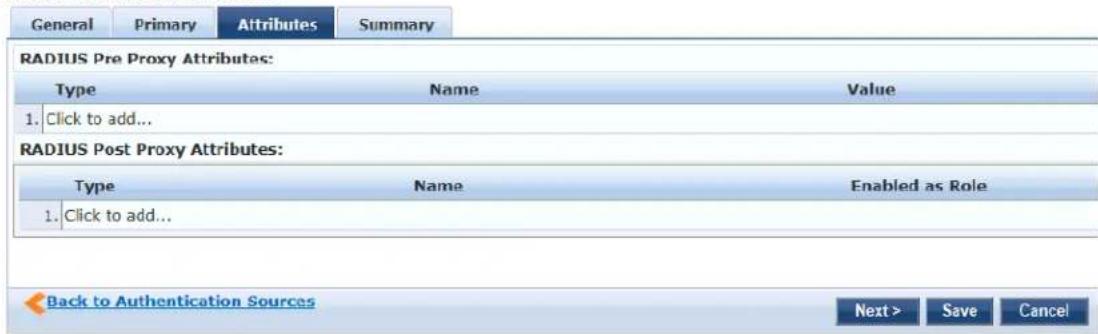
The following table describes the RADIUS Server - Attributes parameters:
Table 120: RADIUS Server - Attributes Tab Parameters
| Parameter Description | |
| RADIUS Pre-Proxy attributes | The following attributes that can be set prior to the proxy authentication:Type - Select a type from the drop-down.Name - Select a name from the drop-down.Value - Enter a value in the text box.Save the changes by clicking the Save icon that appears at the end of the row. |
| RADIUS Post-Proxy attributes | The attributes for the post-proxy authentication are identical except that these can be s the proxy authentication.Type - Select a type from the drop-down.Name - Select a name from the drop-down.Value - Enter a value in the text box.Save the changes by clicking the Save icon that appears at the end of the row. |
Summary Tab
You can use the Summary tab to view configured parameters. The following figure displays the RADIUS Server - Summary tab:
Figure 200: RADIUS Server - Summary Tab
Configuration > Authentication > Sources > Add
Authentication Sources
![General Primary Attributes Summary General: Name: Test Auth Source Description: Testing against the Loca DB. Type: RadiusServer Use for Authorizations: Enabled Authorization Sources: [Local User Repository] [Local] Primary: Server Name: 10.17.4.197 Port: 1812 Secret: ***** Attributes: RADIUS Pre Proxy Attributes: Type Name Value 1. Radius::IETF ARAP-Password = 67 RADIUS Post Proxy Attributes: Type Name Enabled as Role 1. Radius:Microsoft MS-ARAP-PW-Change-Reason = true](/content/2026/05/842116/images/26f1decf40e6b6a90884f776162401cc3c4e6b99bd39a82b472a1de2ae8ec166.jpg)
Adding a Static Host List as an Authentication Source
This section provides the following information:
• About Static Host Lists
- Adding a Static Host List as an Authentication Source
About Static Host Lists
You can configure primary and backup servers, session details, and the list of static hosts for Static Host List authentication sources.
A static host list often functions, in the context of the service, as a white list or a black list. Therefore, static host lists are configured independently at the global level.
A static host list comprises a named list of MAC addresses or IP addresses, which can be invoked in the following ways:
• In service and role-mapping rules as a component.
- For non-responsive services on the network (for example, printers or scanners), as an authentication source.
Only static host lists of type MAC Address are available as authentication sources.
For more information about static host lists, see Managing Static Host Lists on page 268.

Adding a Static Host List as an Authentication Source
To add a static host list as an authentication source:
- Navigate to Configuration > Authentication > Sources.
The Authentication Sources page appears.
Figure 201: Authentication Sources Page
![Configuration > Authentication > Sources Authentication Sources Filter: Name contains Go Clear Filter Show 10 records Name △ Type Description 1. [Admin User Repository] Local SQL DB Authenticate users against Policy Manager admin user database 2. avenda313 Active Directory 3. [blacklist User Repository] Local SQL DB Blacklist database with users who have exceeded bandwidth or session related limits 4. [Endpoints Repository] Local SQL DB Authenticate endpoints against Policy Manager local database 5. [Guest Device Repository] Local SQL DB Authenticate guest devices against Policy Manager local database 6. [Guest User Repository] Local SQL DB Authenticate guest users against Policy Manager local database 7. [Insight Repository] Local SQL DB Insight database with session information for users and devices 8. [Local User Repository] Local SQL DB Authenticate users against Policy Manager local user database 9. [Onboard Devices Repository] Local SQL DB Authenticate Onboard devices against Policy Manager local database 10. [Social Login Repository] Local SQL DB Authenticate users against Policy Manager social login database Shewing 1-10 of 11 ▶ Copy Export Delete](/content/2026/05/842116/images/320c9254d999e7e7456438a6ea4fb34f1883a675fae48195fa0c81fc1138f55d.jpg)
- Click the Add link.
The Add Authentication Sources dialog opens.
Figure 202: Specifying a Static Host List as Authentication Source
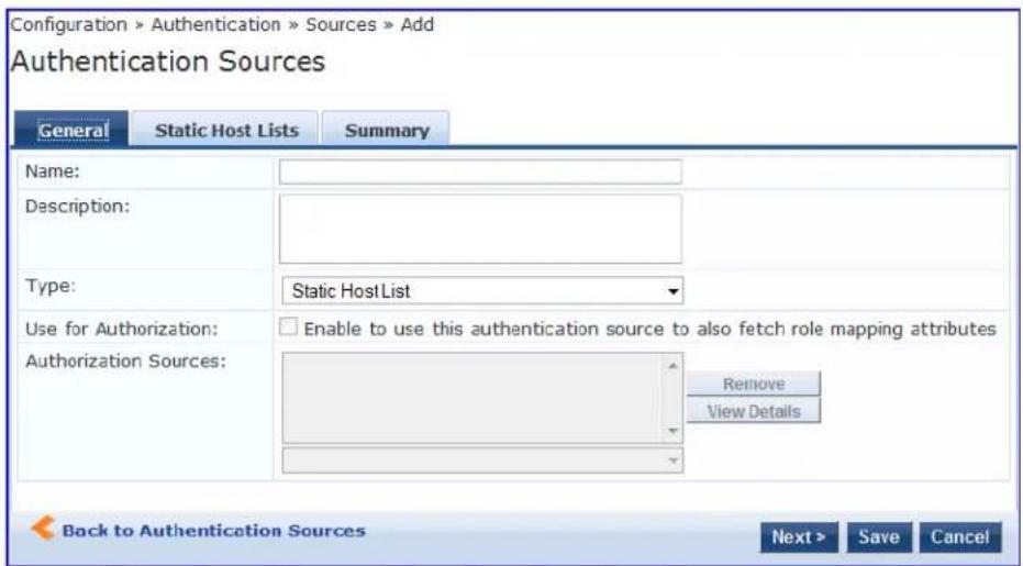
-
Enter the name and description of the static host list.
-
In the Type field, select Static Host List.
In this context, the Use for Authorization and Authorization Sources fields are not configurable.
- Click Next.
The Static Hosts Lists dialog appears.
- From the Static Host Lists tab, select a static host list from the drop-down list.
The selected static host list is added to the MAC Address Host Lists (see Figure 203).
Figure 203: Existing Static Host List Added
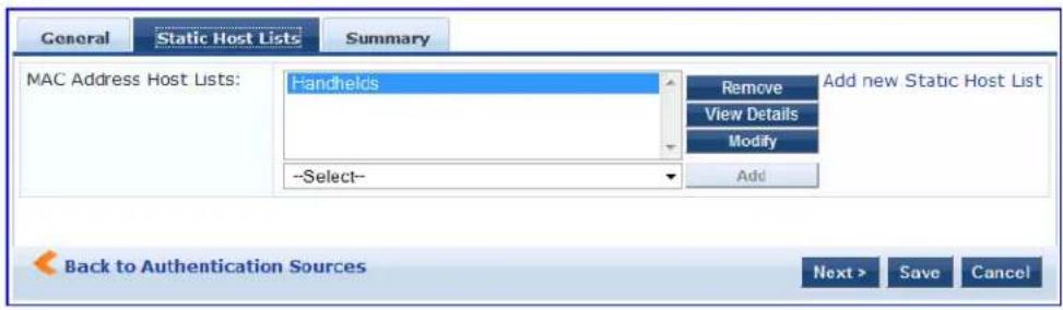
Only static host lists of type MAC Address Host Lists or MAC Address Regular Expression can be configured as authentication sources.
a. To remove the selected static host list, click Remove.
b. To view the contents of the selected static host list, click View Details.
c. To modify the selected static host list, click Modify.
7. Click Save.
Token Server
Policy Manager can perform GTC authentication against any token server than can authenticate users by as a RADIUS server (for example, RSA SecurID Token Server) and can authenticate users against a token and fetch role mapping attributes from any other configured authorization source.
Pair this source type with an authorization source (identity store) containing user records. When using a server as an authentication source, use the administrative interface to optionally configure a separate authorization server. Policy Manager can also use the RADIUS attributes returned from a token server to role mapping policies. For more information, see Namespaces on page 919.
You configure primary and backup servers, session details, and the filter query and role mapping attribute fetch for token server authentication sources on the following tabs:
• General Tab on page 246
• Primary Tab on page 247
• Attributes Tab on page 247
• Summary Tab on page 248

General Tab
The General tab labels the authentication source and defines session details, authorization sources, and backup server details. The following figure displays the Token Server - General tab:
Figure 204: Token Server - General Tab
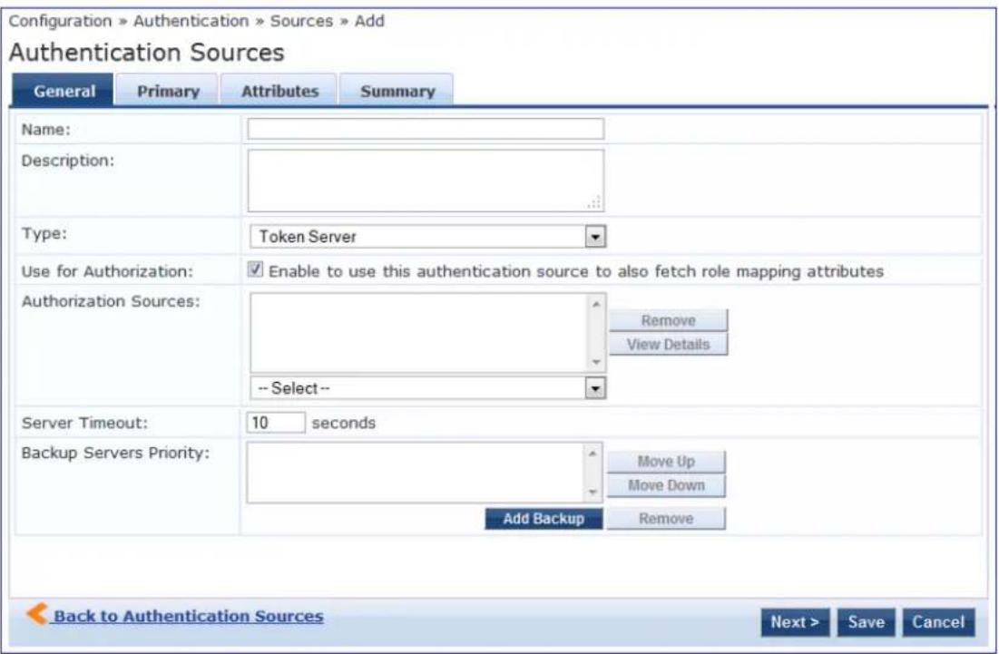
The following table describes the Token Server - General parameters:
Table 121: Token Server - General Tab Parameters
| Parameter Description | |
| Name Specify | the label of the authentication source. |
| Description Provide the additional information that helps to identify the authentication source. | |
| Type | Select the type of authentication. In this context, select Token Server. |
| Use for Authorization | Enable this check box to instruct Policy Manager to fetch role mapping attributes (or auth attributes) from this authentication source. If a user or device successfully authenticates ag this authentication source, then Policy Manager also fetches role mapping attributes from t same source if the Use for Authorization field is enabled. This check box is enabled by default |
| Authorization Sources | Specify additional sources from which to fetch role mapping attributes. Select a previously configured authentication source from the drop-down list, and click Add to add it to the list of authorization sources. Click Remove to remove it from the list.If Policy Manager authenticates the user or device from this authentication source, then it fetches role mapping attributes from these additional authorization sources.NOTE: You can specify additional authorization sources at the service level. Policy Manager fetches role mapping attributes irrespective of which authentication source the user or device was authenticated against. |
| Server Timeout | Specify the duration in seconds that Policy Manager waits before attempting to fail over from primary to backup servers (in the order in which they are configured). |
| Backup Servers Priority | To add a backup server, click Add Backup. From the Backup 1 tab, you can specify connection details for a backup server (same fields as for primary server that are specified below). To remove a backup server, select the server name and click Remove. Select Move Up or Move Down to change the server priority of the backup servers. This is the order in which Policy Manager attempts to connect to the backup servers. |
Primary Tab
The Primary tab defines the settings for the primary server. The following figure displays the Token Server - Primary tab:
Figure 205: Token Server - Primary Tab
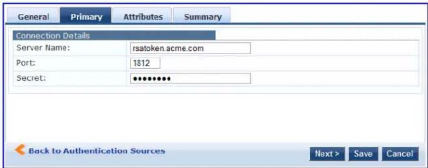
The following table describes the Token Server - Primary parameters:
Table 122: Token Server - Primary Tab Parameters
| Parameter | Description |
| Server Name | Displays the host name or the IP address of the token server, |
| Port Specifies | the UDP port at which the token server listens for RADIUS connections. The default port is 1812. |
| Secret Specify | the RADIUS shared secret to connect to the token server. |
Attributes Tab
The Attributes tab defines the RADIUS attributes to be fetched from the token server. These attributes can be used in role mapping policies. Policy Manager loads all RADIUS vendor dictionaries in the Type drop-down list with attributes.
The following figure is an example of the Token Server - Attributes tab:
Figure 206: Token Server - Attributes Tab
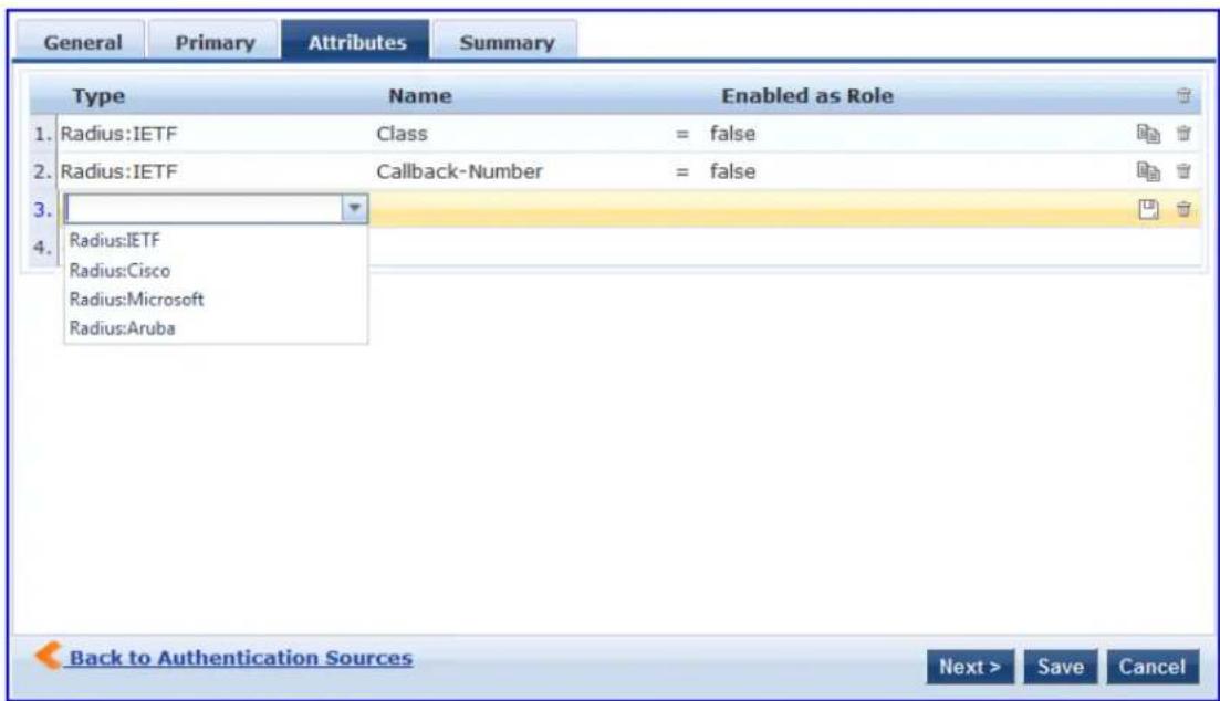
See Configuring a Role and Role-Mapping Policy on page 272 for more information. The following table describes the Token Server - Attribute parameters:
Table 123: Token Server - Attribute Tab Parameters
| Parameter | Description |
| Type Select | the type of authentication source from the drop-down list. |
| Name Specifies the name of the token server attributes. | |
| Enabled as Role | Specifies whether value is to be used directly as a role or attribute in an enforcement policy bypasses the step of assigning a role in Policy Manager through a role mapping policy. |
Summary Tab
The Summary tab provides the summarized view of the parameters configured in the General, Primary, and Attributes tab. The following figure displays the Summary tab:
Figure 207: Token Servers - Summary Tab
Configuration > Authentication > Sources > Add
Authentication Sources
| General | Primary | Attributes | Summary |
| General: | |||
| Name: | Test Auth source | ||
| Description: | Authenticating against the Local DB. | ||
| Type: | TokenServer | ||
| Use for Authorization: | Enabled | ||
| Authorization Sources: | [Local User Repository] [Local] | ||
This chapter provides information on the following topics:
- Configuring Single Sign-On
• Managing Local Users - Adding and Modifying Endpoints
• Managing Static Host Lists - Configuring a Role and Role-Mapping Policy
This chapter provides details on the settings required to configure W-ClearPass Policy Manager Identify settings.
The Policy Manager database supports storage of user records when a particular class of users is not p/a central user repository (for example, when there is neither an Active Directory nor any other database

To authenticate local users from a particular service, include Local User Repository among the authentication sources.
Configuring Single Sign-On
This section provides the following information:
• SAML Service Provider (SP) Configuration
• SAML Identity Provider (IdP) Configuration
The Single Sign-On (SSO) settings on the Single Sign-On page allows W-ClearPass users that have signed in to W-ClearPass Policy Manager to access the Onboard, Guest, and Insight applications and Policy Manager administration settings without reauthenticating. W-ClearPass provides single sign-on support using the Security Assertion Markup Language (SAML).
This feature also provides differentiated single sign-on access for Guest web login and Guest Operator lo (see Table 124 for details).
SAML Service Provider (SP) Configuration
To configure single sign-on service provider settings:
- Navigate to Configuration > Identity > Single Sign-On. The Single Sign-On > SAML SP Configuration dialog opens.
Figure 208: Configuring Single Sign-On > SAML Service Provider Parameters
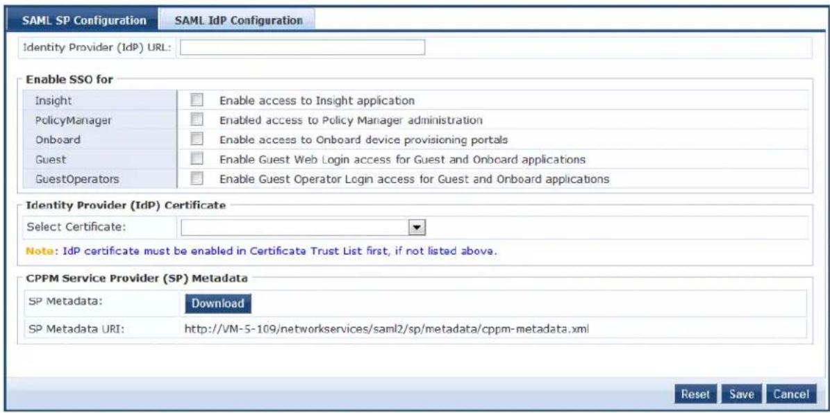
- Select the application(s) you want users to access with single sign-on.
To complete this task, specify the SAML SP Configuration tab parameters as described in Table 124.
- Create trusted relationships between a Service Provider and Identity Provider by providing the Identity Provider (IdP) URL and IdP certificate.
To complete this task, specify the SAML IdP Configuration tab parameters as described in Table 125.
Table 124: Single Sign-On Service Provider Configuration Settings
| Parameter Action/Description | |
| Identity Provider(IdP) URL | 1. Enter the URL of the identity provider. |
| Enable SSO For 2. Select the applications to be enabled for single sign-on:InsightPolicy ManagerOnboard device provisioning portalsGuest and Onboard Web LoginGuest and Onboard Guest Operator LoginIf you select only the Guest Operator Login, SSO will be enabled for Operator logins only, and Web logins will use standard non-SSO authentication.If you select only the Guest Web Login option, SSO will be enabled for Web logins only, and Operator logins will use standard non-SSO authentication.If you select both the Guest Operator Login and the Guest Web Login options, Operator logins and Web logins will both use SSO authentication. | |
| Select Certificate 3. Select the Identity Provider (IdP) certificate to use for single sign-on. When you select a certificate, the page displays the following information about the certificate:Subject DNIssuer DNIssue Date/TimeExpiry Date/Time | |
| Validity StatusSignature AlgorithmPublic Key FormatSerial NumberEnabledThis field only displays certificates that are enabled in the certificate trust list. See also Certificate Trust List on page 681. | |
| CPPM Service Provider (SP) Metadata | SP Metadata:4. To download and view an XML file containing metadata for the Service Provider Uniform Resource Identifier (URI), click Download.Metadata URI :5. View the Uniform Resource Identifier (URI) for the Service Provider metadata resource. |
SAML Identity Provider (IdP) Configuration
To configure single sign-on identity provider settings:
-
Navigate to Configuration > Identity > Single Sign-On.
-
Select the SAML IdP Configuration tab.
Figure 209: Configuring Single Sign-On > Identity Provider Parameters
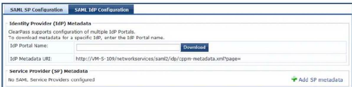
- Specify the SAML IdP Configuration parameters as described in the following table:
Table 125: Single Sign-On Identity Provider Configuration Settings
| Parameter Action/Description | |
| IdP Portal Name 1. Enter the name of the identity provider portal.2. To download and view an XML file containing metadata for the Identity Provider Uniform Resource Identifier (URI), click Download. | |
| IdP Metadata URI 3. View the Uniform Resource Identifier (URI) for the IdP metadata resource. | |
| Service Provider (SP) Metadata | 4. If you upload metadata for an SAML Service Providers, W-ClearPass can upload the SP metadata for validation during the single-sign on process.a. Click Add SP Metadata.b. Enter the name of the service provider.c. Upload the service provider metadata file. |
| CPPM Service Provider (SP) Metadata | SP Metadata section:5. To download and view an XML file containing metadata for the Service Provider Uniform Resource Identifier (URI), click Download.The Metadata URI:6. View the location of this metadata file. |
Managing Local Users
This section provides the following information:
- Adding a Local User
- Modifying a Local User Account
- Importing and Exporting Local Users
- Setting Password Policy for Local Users
• Disabling Local User Accounts
W-ClearPass Policy Manager lists all local users in the Local Users page.
You can also add, import, export, set password policies, and configure the conditions for disabling account the local users using the links provided at the top-right corner of the Local Users page.
Adding a Local User
To add a local user in the Local Users table:
- Navigate to Configuration > Identity > Local Users.
The Local Users page opens.
Figure 210: Local Users Page
![Configuration > Identity > Local Users Local Users Filter: User ID contains Go Clear Filter Show 10 records User ID ▲ Name Role Status 1. m1 m1 [Employees] Enabled Showing 1-1 of 1 Export Delete Add Import Export All Account Settings](/content/2026/05/842116/images/bc54e37041e422225feabaa7691d2851f2d1a3d3a45969cc93da175ff8148328.jpg)
- Click the Add link at the top-right corner the page.
The Add Local User page opens (see Figure 211).
Figure 211: Adding a Local User
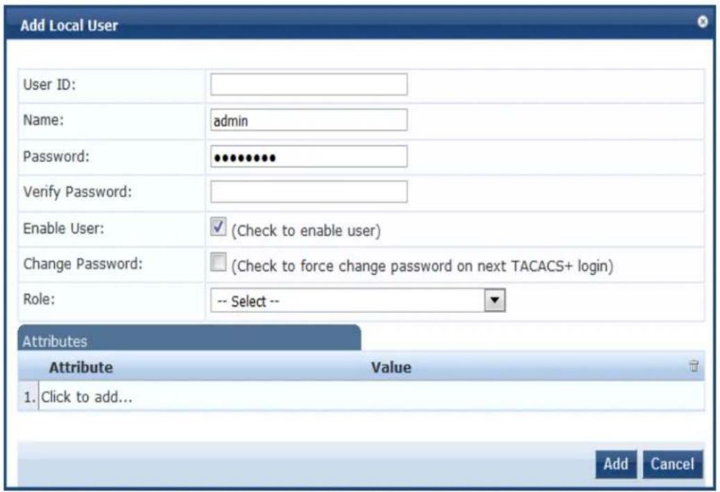
- Specify the Add Local User parameters as described in the following table, then click Add:
Table 126: Adding a Local User Parameters
| Parameter Action/Description | |
| User ID 1. Specify the local user's user ID. | |
| Name 2. Enter the local user's name. | |
| Password/ Verify Password 3. Specify a password for the local user, then verify the password. | |
| Enable User 4. You must enable this check box to enable the local user account. Otherwise, the local user account is disabled. | |
| Change Password 5. Enable this check box to allow the user to change the password at the next TACACS+ login (after authenticating with the old password).Once the password is changed successfully, this option is automatically disableNOTE: The option to change the password on the next login is applicable for network device administration logins using TACACS+ only. | |
| Role | 6. Select a static role to be assigned to the user from the Role drop-down list. |
| Attributes | |
| 7. To add attributes for the local users, click Click to add...A new row is created with a drop-down list in the Attribute column. This field is optional. The list of local user attributes are:DepartmentDesignationEmailPhoneSponsorTitlea. To add a custom attribute in the Attribute column, select an attribute from the drop-down list or enter any string.NOTE: If you add a new custom attribute, it is available for selection in the Attribute drop-down list for all local users.b. In the Value column, enter a value for the attribute specified in corresponding row.NOTE: All attributes entered for a local user are available in the role-mapping editor under the LocalUser namespace.When you click Add, you return to the Local User page where the following message is displayed:Useradded successfully | |
Modifying a Local User Account
To modify a local user account:
- Navigate to the Configuration > Identity > Local Users page.
- Click the User ID row that you want to edit.
The Edit Local User window opens.
Figure 212: Modifying a Local User
![Edit Local User User ID: m1 Name: m1 Password: •••••••••••••••• Verify Password: ••••••••••••••••• Enable User: ✓ (Check to enable user) Change Password: □ (Check to force change password on next TACACS+ login) Role: [Employee] Attributes Attribute Value 1. Title = Director of Sales 2. Click to add... Save Cancel](/content/2026/05/842116/images/479539389b3f128c5bc8a64ae57e6d96269b00a49850de3c2a511dcc135d356d.jpg)
- Modify any values as necessary in the Edit Local User dialog.
- Click Save.
Importing and Exporting Local Users
You can import or export the admin user accounts by using the Import and Export All links at the top-right corner of the Local Users page.
For more information, see Importing and Exporting Information on page 32.
After selecting one or more user accounts from the list, you can also export specific user accounts by c the Export button.

The passwords of the local user accounts are not stored in clear text when exported to an XML file.
Setting Password Policy for Local Users
To set password policies for the local users:
- Navigate to the Configuration > Identity > Local Users page.
- Click the Account Settings link.
The Account Settings page opens.
Figure 213: Account Settings > Password Policy Settings Dialog
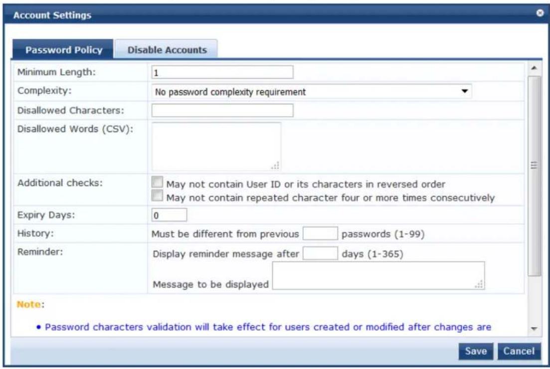
- Specify the Password Policy parameters as described in Table 127, then click Save.
Table 127: Password Policy Parameters
| Parameter Action/Description | |
| Minimum Length 1. Specify the minimum length required for the password. | |
| Complexity | 2. Select the complexity setting from the Complexity drop-down list. The complexity settings can be one of the following:No password complexity requirementAt least one uppercase and one lowercase letterAt least one digitAt least one letter and one digitAt least one of each: uppercase letter, lowercase letter, digitAt least one symbolAt least one of each: uppercase letter, lowercase letter, digit, and symbol |
| Disallowed Characters 3. Specify the characters not to be allowed in the password.NOTE:Password characters validation takes effect for users created or modified after changes are saved. | |
| Disallowed Words (CSV) | 4. Specify the words not to be allowed in the password. Separate the disallowed words with commas. |
| Additional Checks | 5. Select any additional checks, if required. The options are: |
| ■ May not contain User ID or its characters in reversed order.■ May not contain a repeated character four or more times consecutively. | |
| Expiry Days 6. Set the password | expiration time for local users.The allowed range is 0 to 500 days. The default value is 0.NOTE: If the value is set to 0, the password never expires. For any other value, local users are forced to reset the expired password when they W-ClearPass alerts users five days before the password expires. |
| History 7. Specify the number of | previous passwords for this user to be compared against.This option prevents users from setting a password that was used recently. Valid options are from 1 to 99. |
| Reminder 8. Configure the reminder | message.Setting this option displays a reminder after n days to change the password. The valid options are from 1 to 365. When set, this option only displays a reminder; it does not prompt for a new password.The message to be displayed can be set accordingly.NOTE: The Reminder parameter is applicable for TACACS+ authentication only. The other settings are applied to all users. |
Disabling Local User Accounts
Disabling a local user account can happen in two ways:
- When a local user tries to log in with an invalid password for a configured number of times defined by the Failed attempts count parameter, the local user account is locked.
If the mechanism for logging in to W-ClearPass Policy Manager is Certificate + Password, the local user is allowed to enter the password even if the certificate is invalid.
- When the local user tries to log in with an invalid user certificate for a configured number of times defined by the Failed attempts count parameter, the local user account is disabled.
A local user's failed login attempts are counted only when the Password_Mismatch, Password_Not_Available, and User_Authentication_Failed error messages occur.
- To reset the Failed attempts count and enable a disabled local user account, click the Reset button (see Table 128).
- For Local users whose accounts are locked due to account settings validations, and whose accounts are enabled again after being locked out, entries are logged in both the Audit Viewer (see Audit Viewer on page 167) and the Event Viewer (see Event Viewer on page 169).
The Disable Account check occurs every day at midnight, except for the Failed attempts count. Other local user configuration settings are applied to all local users.
To specify the conditions for disabling local user accounts:
- Navigate to Configuration > Identity > Local Users.


- Click the Account Settings link.
The Account Settings page opens.
- Select the Disable Accounts tab.
The Disable Accounts dialog opens.
Figure 214: Disable Accounts Dialog
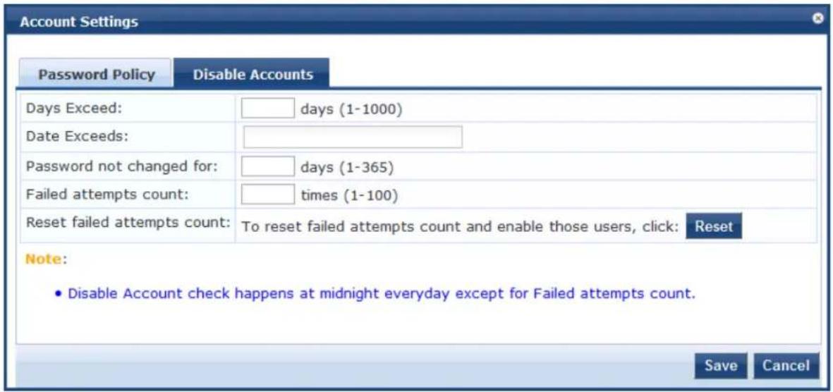
- Specify the Disable Accounts parameters as described in Table 128, then click Save.
Table 128: Disable Accounts Parameters
| Parameter Action/Description | |
| Days Exceed 1. Specify the number of days before the account is disabled.The range is from 1 to 100 days. | |
| Date Exceeds 2. Specify the date when local users are disabled when the current date exceeds the configured date.The configured date can either be the current system date or a future date.Entering a date prior to the current date is not supported. | |
| Password not changed for | 3. Specify the number of days allowed before the password must be changedThe range is from 1 to 365 days. |
| Failed attempts count | 4. Specify the number of failed log-in attempts are allowed before the account is disabled.The range is from 1 to 100 attempts. |
| Reset failed attempts count | 5. To reset the failed attempts count to zero and reenable those local users who were disabled after exceeding the failed attempts count, click Reset. |
Adding and Modifying Endpoints
This section provides the following information:
• Viewing the List of Authentication Endpoints
• Viewing Endpoint Authentication Details
• Performing Bulk Updates of Endpoint Attributes
- Triggering Actions to Be Performed on Endpoints
- Updating Device Fingerprints From a Hosted Portal
• Manually Adding an Endpoint
- Modifying an Endpoint
For related information, see:
- Configuring Endpoint Context Server Actions on page 614
- Adding Vendor-Specific Endpoint Context Servers on page 619
Viewing the List of Authentication Endpoints
W-ClearPass Policy Manager automatically lists all the endpoints that are authenticated in the Configuration > Identity > Endpoints page.
Figure 215: Endpoints Page
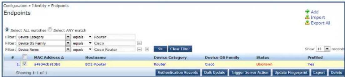
Table 129: Endpoint Page Parameters
| Parameter Action/Description | |
| Filters | You can choose to selectALL matchesorANY matches.Then you can specify from one to three device filters to refine the endpoint informatic wish to view. |
| MAC Address Displays the MAC address of the endpoint. | |
| Hostname Specifies the host name of the endpoint. | |
| Device Category | Indicates the category of the profiled device. For example, Access Points, Computer, Smart Device, VoIP phone, and so on. |
| Device OS Family | Specifies the operating system that the device runs on. For example, when the category Computer, W-ClearPass shows a Device OS Family of Windows, Linux, or Mac OS X. |
| Status Displays the status of the endpoint:UnknownKnown clientUnknown clientDisabled client | |
| Profiled Indicates whether the device has been added to the W-ClearPass Profile. | |
Viewing Endpoint Authentication Details
To view the authentication details of an endpoint:
- From the Configuration > Identity > Endpoints page, select an endpoint by the clicking the corresponding check box.
The Authentication Records button is now enabled.
- Click the Authentication Records button.
The Endpoint Authentication Details page opens.
Figure 216: Endpoint Authentication Details
| MAC Address | 001644b19320 | ||||
| Username | Device | Authentication | Start Time | Policy Manager Server | Session ID |
| 1 | 10.2.50.29 | ACCEPT | 2012/04/25 11:23:17 | 10.2.50.177 | R00000175-01-4f984115 |
| 2 | 10.2.50.29 | ACCEPT | 2012/04/25 11:23:03 | 10.2.50.177 | R00000174-01-4f984107 |
| 3 | 10.2.50.29 | ACCEPT | 2012/04/25 11:17:45 | 10.2.50.177 | R00000173-01-4f983fc9 |
| 4 | 10.2.50.29 | ACCEPT | 2012/04/25 11:17:31 | 10.2.50.177 | R00000172-01-4f983fba |
| 5 | 10.2.50.29 | ACCEPT | 2012/04/25 11:11:59 | 10.2.50.177 | R00000171-01-4f983e6e |
| 6 | 10.2.50.29 | ACCEPT | 2012/04/25 11:06:39 | 10.2.50.177 | R00000170-01-4f983d2f |
| 7 | 10.2.50.29 | ACCEPT | 2012/04/25 11:06:26 | 10.2.50.177 | R0000016f-01-4f983d22 |
| 2012/04/25 | |||||
Performing Bulk Updates of Endpoint Attributes
You can perform bulk updates of endpoint attributes, either for a single endpoint or for multiple endpoints simultaneously.
To perform bulk updates of endpoint attributes:
- From the Configuration > Identity > Endpoints page, select one or more endpoints by the clicking the corresponding check boxes.
The Bulk Update button is now enabled.
In network discovery, when endpoints do not have a MAC address, W-ClearPass creates MAC addresses for them that include the prefix xa.
- Click the Bulk Update button.
The Bulk Update Attributes dialog opens.
Figure 217: Configuring Bulk Update Attributes
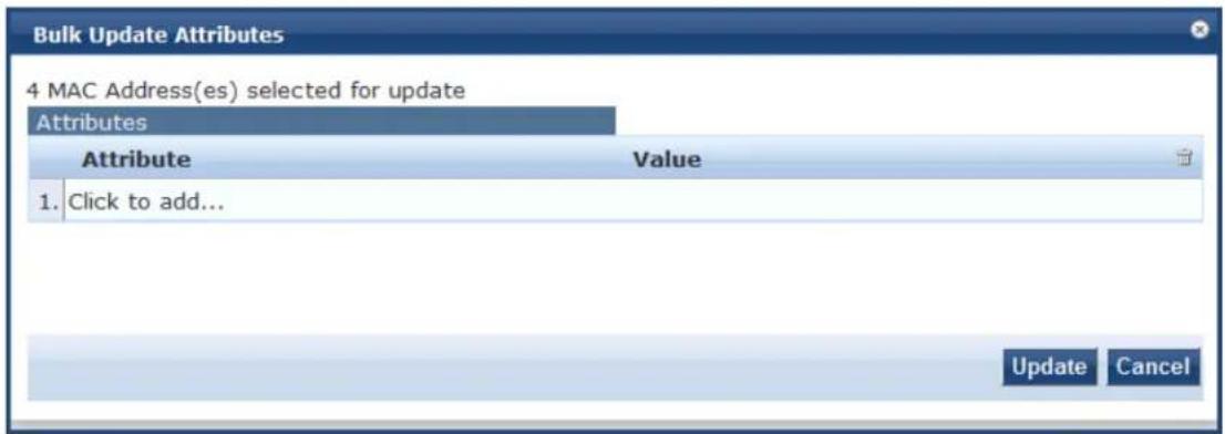
- To select an attribute you want to update, select Click to add, select the attribute from the Attribute list, and then specify its Value.
- Repeat the selection process for all the attributes you want to update, then click Update.
The multiple attributes that were configured will be updated on all the selected endpoints at once.
Triggering Actions to Be Performed on Endpoints
You can trigger endpoint actions for a single endpoint or for multiple endpoints simultaneously.
To trigger actions that are to be performed on selected endpoints:
- From the Configuration > Identity > Endpoints page, select one or more endpoints from the Endpoints page by clicking the corresponding check boxes.
The Trigger Server Action button is now enabled.
- Click the Trigger Server Action button.
The Trigger Server Action page opens:
Figure 218: Endpoints > Trigger Server Action Page
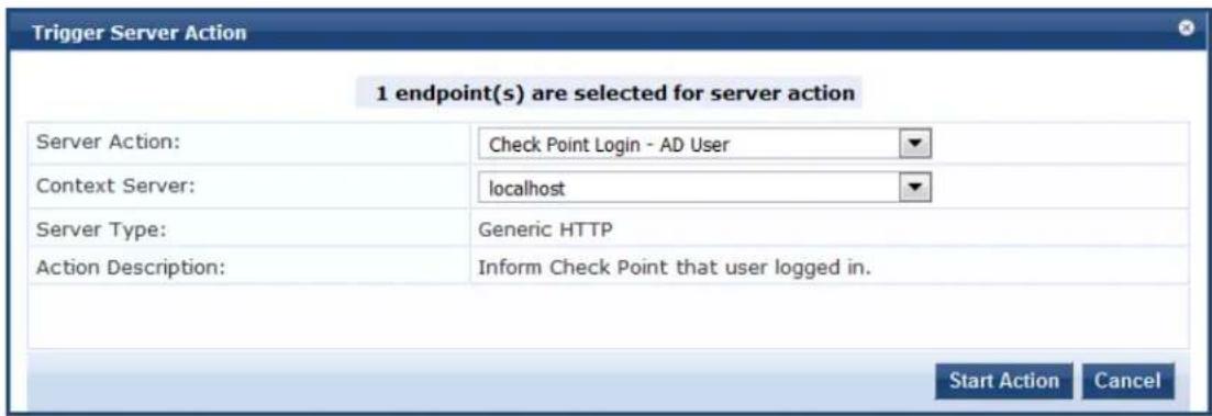
- Specify the Trigger Server Action page parameters as described in the following table, then click Start Action:
Table 130: Trigger Server Action Page Parameters
| Parameter Action/Description | |
| Server Action Select the server action from the drop-down list. The available server actions are as follows:Check Point Login - AD UserCheck Point Logout - Guest UserFortinet LoginFortinet LogoutHandle AirGroup Time SharingInfoblox LoginNmap ScanSNMP Scan | |
| Context Server Enter a valid context server name. You can enter an IP address or domain name. | |
| Server Type Indicates the server type specified when the server was configured. | |
| Action Description | Describes the action that will take place on the endpoint; for example, "Inform Check Point that user logged in." |
Updating Device Fingerprints From a Hosted Portal
You can update device fingerprints for a single endpoint or for multiple endpoints simultaneously.
To update device fingerprints from a hosted portal:
- From the Configuration > Identity > Endpoints page, select one or more endpoints by clicking the corresponding check boxes.
The Update Fingerprint button is now enabled.
- Click the Update Fingerprint button.
The Update Device Fingerprint page opens. By default, the Update Type is set to Override fingerprint (see Figure 219).
Figure 219: Update Device Fingerprint Page: Override Fingerprint
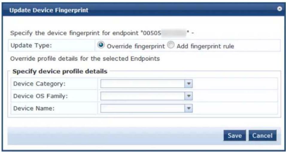
Figure 220 shows the Update Device Fingerprint page when you set the Update Type to Add fingerprint rule.
Figure 220: Update Device Fingerprint Page: Add Fingerprint Rule
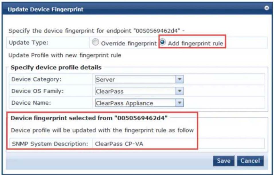
- Specify the Update Device Fingerprint page parameters as described in the following table, then click Save:
Table 131: Update Device Fingerprint Parameters
| Parameter | Action/Description |
| Update Type | Select one of the following update types:Override fingerprint: Update the device profile details (device category, device OS family, and device name) for the selected endpoint.Add fingerprint rule: Update the device profile with a new fingerprint rule. This information is displayed at the bottom of the Update Device Fingerprint page, as shown in Figure 220. |
| Specify Device Profile Details | |
| Device Category | Select the category the profiled device belongs to. |
| Device OS Family | Select the operating system configured on the device. |
| Device Name | Enter the name of the device. You can select the name of the device from the list. |
Manually Adding an Endpoint
To manually add an endpoint:
- From the Configuration > Identity > Endpoints page, click Add.
The Add Endpoint page opens.
Figure 221: Add Endpoint Page
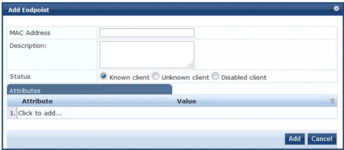
- Specify the Add Endpoint page parameters as described in the following table, then click Save:
Table 132: Add Endpoint Page Parameters
| Parameter | Action/Description |
| MAC Address | Specify the MAC address of the endpoint. |
| Description | Enter a description that provides additional information about the endpoint (recommended). |
| Status Specify the client status as:Known clientUnknown clientDisabled clientYou can use the Known client and Unknown client status in role-mapping rules by specifying the Authentication:MacAuth attribute.You can use the Disabled client status to block access to a specific endpoint. This status is automatically set when an endpoint is blocked from the Endpoint Profiler. | |
| Attributes | Add custom attributes for this endpoint.Select the Click to add... row to add custom attributes.You can enter any name in the attribute field. All attributes are of String datatype.The Value field can also be populated with any string.Each time you enter a new custom attribute, it is available for selection in the Attribute drop-down list for all endpoints. All attributes entered for an endpoint are available in the role-mapping Editor. |
Modifying an Endpoint
- Modifying an Endpoint
- Configuring the Attributes for the Selected Endpoint
• Endpoint Fingerprint Details Page
To modify an endpoint:
- From the Configuration > Identity > Endpoints page, click the endpoint of interest from the list of endpoints.
The Edit Endpoint page opens.
Modifying an Endpoint
Figure 222: Edit Endpoint Page
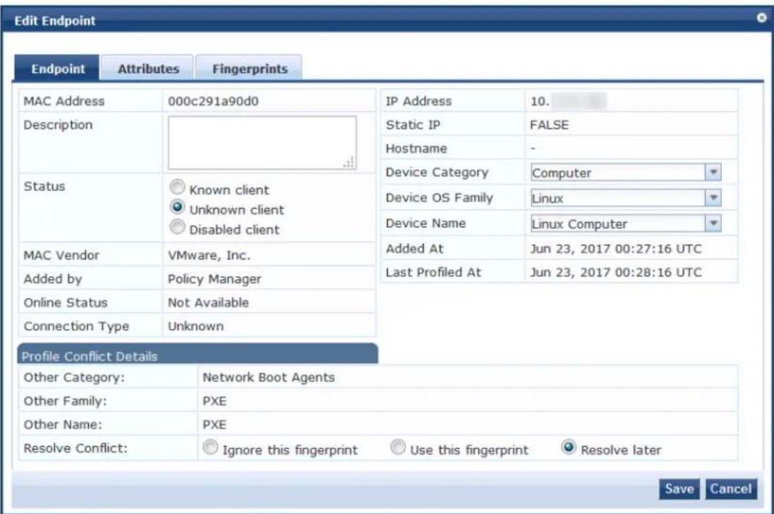
- Specify the Edit Endpoint page parameters as described in the following table, then click Save:
Table 133: Edit Endpoint Page Parameters
| Parameter Action/Description | |
| MAC Address Displays the MAC address of the endpoint. | |
| Description Enter a description that provides additional information about the endpoint (recommended). | |
| Status Indicate the status of the selected endpoint as:Known clientUnknown clientDisabled clientYou can use the Known client and Unknown client status in role-mapping rules by applying the Authentication:MacAuth attribute.You can use the Disabled client status to block access to a specific endpoint. This status is automatically set when an endpoint is blocked from the Endpoint Pro | |
| MAC Vendor | Displays the MAC OUI (Organizationally Unique Identifier) information for all endpointseven when no other profiling information is available for an endpoint. |
| Added by Displays the name of the W-ClearPass server that added the endpoint. | |
| Online Status Displays the online status of the endpoint: · Online · Not Available | |
| Connection Type Indicates the connection type; for example, Wireless. If the connection type is not known, the connection type is displayed as Unknown. | |
| Network SSID Indicates the SSID of the network in which the endpoint is deployed. | |
| IP Address Displays the IP address that is associated with the endpoint. | |
| Static IP | Indicates whether the IP address of the endpoint is a static IP address (True or False). |
| Hostname | Displays the host name or the IP address of the endpoint. |
| Device Category | Select the device category that the endpoint belongs to from the drop-down list. |
| Device OS Family | Specify the operating system that the endpoint runs on. |
| Device Name | Select the name of the device from the drop-down list. |
| Added At | Displays the date and time at which the endpoint was added. |
| Updated At | Displays the date and time at which the endpoint was updated. |
| Last Profiled At | Displays the date and time at which the endpoint was added to the W-ClearPass Profile. |
| Profile Conflict Details | |
| Other Category | Specify if this device can be assigned to an alternate device category. |
| Other Family Specify if this device can be assigned to an alternate OS family. | |
| Other Name | Specify if this device can be assigned to an alternate device name. |
| Resolve Conflict | Select one of the following options to be executed in the event of a conflict: · Ignore the fingerprint · Use the fingerprint · Resolve later |
Configuring the Attributes for the Selected Endpoint
To configure the endpoint attributes for the selected endpoint:
- From the Edit Endpoint page, select the Attributes tab.
Figure 223: Adding Endpoint Attributes
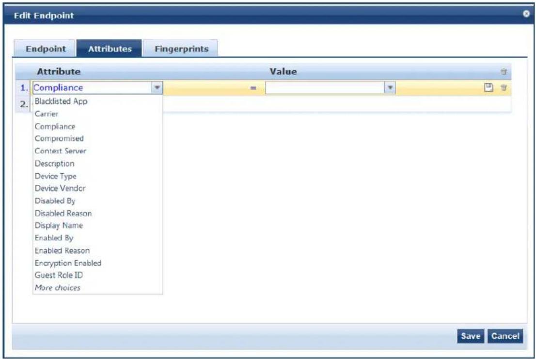
- To add attributes for the selected endpoint, select Click to add...
A new row is created with a drop-down list in the Attribute column.
- To add an attribute to the endpoint, select one or more attributes from the drop-down list, then click Save.
The Compliance attribute is fetched from an Airwatch server and available in the endpoint attributes list. The values for the Compliance attribute are NotAvailable, NonCompliant, or Compliant.
Viewing the Endpoint Fingerprint Details
The information displayed in the Edit Endpoint > Fingerprints page varies depending on what type of device is selected and whether an Nmap-based network discovery scan has been run (see Configuring Nmap-Based Endpoint Port Scans on page 166).
As shown in Figure 224, the Endpoint Fingerprints Details page shows the active and inactive Windows services and processes for the selected Windows endpoint. Service names are listed alphabetically.

Figure 224: Endpoint Fingerprint Details Page
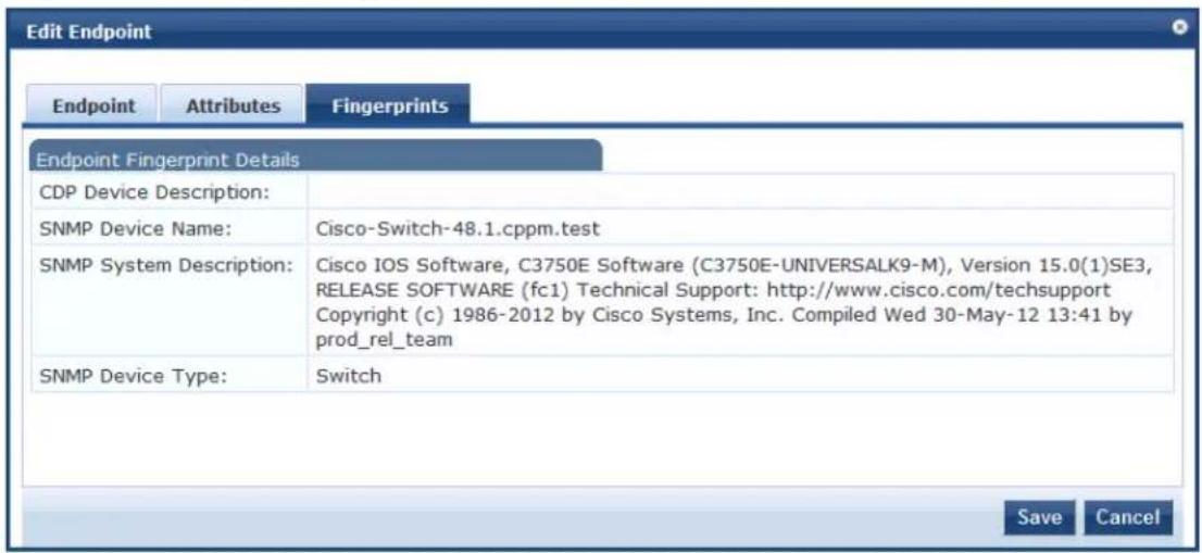
Managing Static Host Lists
This section provides the following information:
• About Static Host Lists
- Adding a Static Host List
• Static Hosts Lists Configuration Summary
• Editing a Static Host List
- Importing and Exporting Static Host Lists
About Static Host Lists
You can configure primary and backup servers, session details, and the list of static hosts for Static Host List authentication sources.
A static host list often functions, in the context of the service, as a white list or a black list. Therefore, static host lists are configured independently at the global level.
A static host list comprises a named list of MAC addresses or IP addresses, which can be invoked in the following ways:
• In service and role-mapping rules as a component.
- For non-responsive services on the network (for example, printers or scanners), as an authentication source. For more information, see Adding a Static Host List as an Authentication Source on page 243.

Only static host lists of type MAC address are available as authentication sources.
Internal Relational Database
An internal relational database stores the W-ClearPass Policy Manager configuration data as well as locally configured user and device accounts.
The following predefined authentication sources represent the databases used to store local users, guest and registered devices respectively:
• [Local User Repository]
• [Guest User Repository]
• [Guest Device Repository]
While regular users reside in an authentication source such as Active Directory (or in other LDAP-compliance stores), you can configure the temporary users, including guest users, in the Policy Manager local repository.
Role Statically Assigned
For a user account created in a local database, the role is statically assigned to that account. This mean not need to specify a role-mapping policy for user accounts in the local database.
However, if new custom attributes are assigned to a user account (local or guest) in the local database, can be used in role-mapping policies.
Preconfigured Filter
The local user database is pre-configured with a filter to retrieve the password and the expiry time for the account. Policy Manager can perform MSCHAPv2 and PAP/GTC authentication against the local database.
Adding a Static Host List
To add a static host list to W-ClearPass:
- Navigate to the Configuration > Identity > Static Host Lists page.
The Static Hosts Lists page opens.
Figure 225: Static Host Lists Page
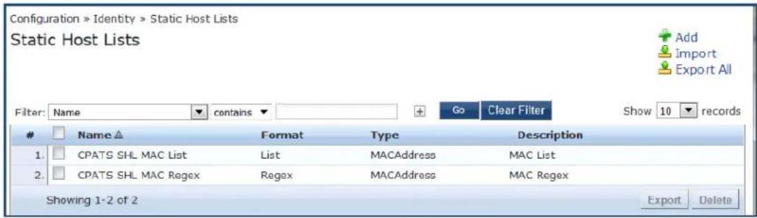
- Click Add.
The Add Static Host List dialog opens.
Figure 226: Adding a Static Host List
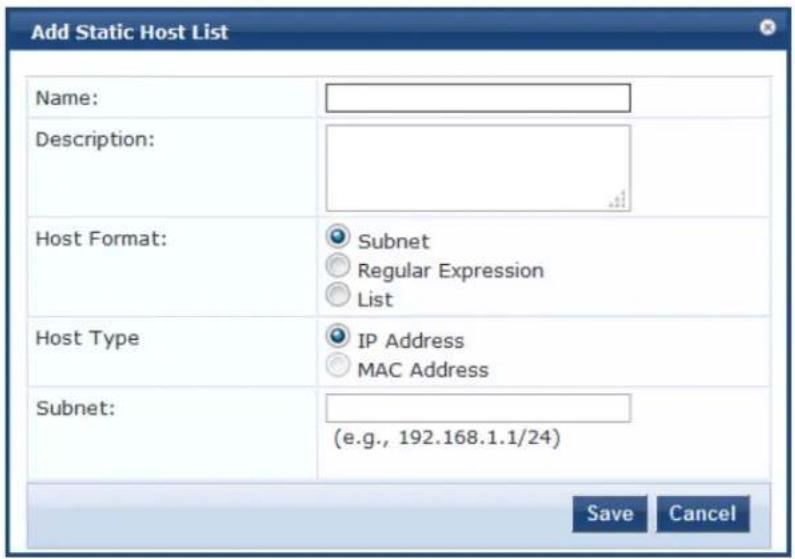
- Specify the parameters to add a static host list as described in Table 134, then click Save.
Table 134: Add Static Host List Parameters
| Parameter Action/Description | |
| Name 1. Enter | the name of the static host list. |
| Description 2. | Enter the description that provides additional information about the static host list. |
| Host Format 3. | Select a format for expression of the address:SubnetRegular ExpressionList |
| Host Type | 4. Select a host type:IP AddressMAC Address |
| Subnet | 5. Enter the subnet address. |
The new static host list is now available to be added as an authentication source. For details, see Adding a Static Host List as an Authentication Source on page 244.
Static Hosts Lists Configuration Summary
You can use the Summary tab to view the static host list's configuration information.
Figure 227: Static Hosts Lists Configuration Summary
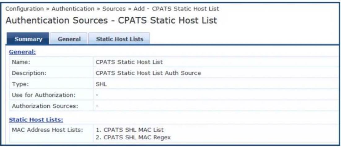
Editing a Static Host List
To edit a static host list:
- Navigate to the Configuration > Identity > Static Host Lists page.
The Static Hosts Lists page opens.
- Click on the name of the static hosts list you want to edit.
The Edit Static Host List dialog opens.
Figure 228: Edit Static Host List Dialog
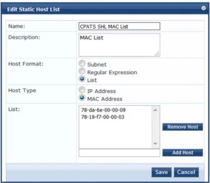
- Make any required changes, then click Save.
Importing and Exporting Static Host Lists
You can import static host lists into W-ClearPass or export them to a file.
- Navigate to the Configuration > Identity > Static Host Lists page. The Static Hosts Lists page opens.
- Click on the name of the static hosts list you want to import or export.
- To import a static host list into W-ClearPass, click the Import link.
- To export a static host list to a file, click the Export All link. For further details, see Importing and Exporting Information on page 32.
Configuring a Role and Role-Mapping Policy
This section includes the following information:
• Preconfigured Roles
- Adding and Modifying Roles on page 274
- Adding and Modifying Role-Mapping Policies on page 275
After authenticating a request, a Policy Manager service invokes its role-mapping policy, resulting in assignment of a role(s) to the client. This role becomes the identity component of enforcement policy decisions.
A service can be configured without a role-mapping policy, but only one role-mapping policy can be configured for each service.

Preconfigured Roles
Policy Manager provides the following preconfigured roles:
• [AirGroup v1]: Role for an AirGroup protocol version 1 request.
• [AirGroup v2]: Role for an AirGroup protocol version 2 request.
- [Aruba TACACS read-only Admin]: Default role for read-only\ access to Dell device.
• [Aruba TACACS root Admin]: Default role for root access to Dell device.
- [BYOD Operator]: Operators with this profile can view and manage their own provisioned devices.
• [Contractor]: Default role for a contractor
- [Device Registration]: Operators with this profile can self-provision their devices for MAC authentication and AirGroup sharing.
• [Employee]: Default role for an employee.
• [Guest]: Default role for guest access.
• [MAC Caching]: Default role applied during MAC caching.
- [Onboard Android]: Role for an Android device being provisioned.
- [Onboard Chromebook]: Role for a Chromebook device being provisioned.
- [Onboard iOS]: Role for an iOS device being provisioned.
- [Onboard Linux]: Role for a Linux device being provisioned.
- [Onboard Mac OS X]: Role for a Mac OS X device being provisioned.
- [Onboard Windows]: Role for a Windows device being provisioned.
• [Other]: Default role for another user or device
• [TACACS API Admin]: API administrator role for Policy Manager admin
• [TACACS Help Desk]: Policy Manager Admin role, limited to views of the Monitoring screens
• [TACACS Network Admin]: Policy Manager Admin role, limited to Configuration and Monitoring screens
• [TACACS Read-only Admin]: Read-only administrator role for Policy Manager Admin
• [TACACS Receptionist]: Policy Manager Guest provisioning role
• [TACACS Super Admin]: Policy Manager Admin role with unlimited access to all user interface screens
Identity Roles Architecture and Workflow
Roles can range in complexity from a simple user group (for example, Finance, Engineering, or Human Resources) to a combination of a user group with some dynamic constraints (for example, "Night Shift W an employee in the Engineering department who logs in through the network device between 8:00 p.m. 5:00 a.m on weekdays). It can also apply to a list of users.
A Role-Mapping Policy reduces client (user or device) identity or attributes associated with the request to Role(s) for Enforcement Policy evaluation. The roles ultimately determine differentiated access.
For more information, see Configuring a Role and Role-Mapping Policy on page 272.
Figure 229 illustrates the role-mapping process and workflow.
Figure 229: Role-Mapping Process
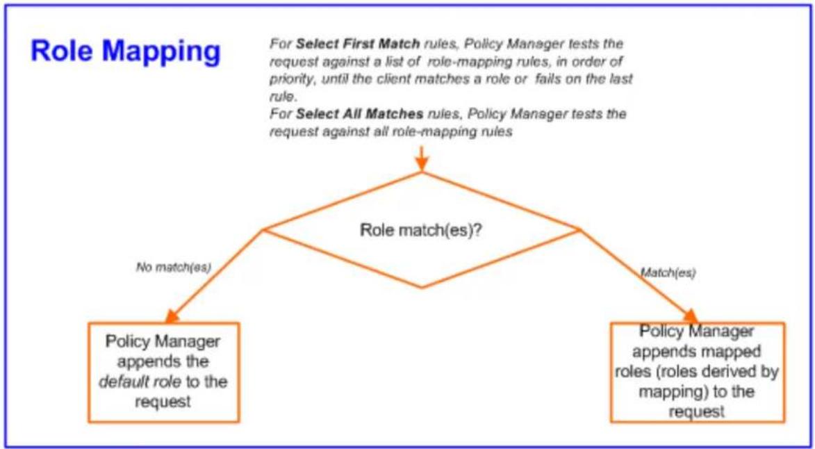
flowchart
graph TD
    A["Role matching"] --> B{Role match(es)?}
    B -->|No match(es)| C["Policy Manager appends the default role to the request"]
    B -->|Match(es)| D["Policy Manager appends mapped roles (roles derived by mapping) to the request"]
    E["For Select First Match rules, Policy Manager tests the request against a list of role-mapping rules, in order of priority, until the client matches a role or fails on the last rule."] --> F["For Select All Matches rules, Policy Manager tests the request against all role-mapping rules"]
A role can be:
- Authenticated through predefined single sign-on rules.
• Associated directly with a user in the Policy Manager local user database.
- Authenticated based on predefined allowed endpoints.
• Associated directly with a static host list, again through role mapping.
- Discovered by Policy Manager through role mapping. Roles are typically discovered by Policy Manager by retrieving attributes from the authentication source. Filter rules associated with the authentication source tell Policy Manager where to retrieve these attributes.
- Assigned automatically when retrieving attributes from the authentication source. Any attribute in the authentication source can be mapped directly to a role.
Adding and Modifying Roles
Roles exist independently of an individual service and can be accessed globally through the role-mapping of any service.
Policy Manager lists all available roles in the Roles page.
To add a role:
1. Navigate to Configuration > Identity > Roles.
The Roles page opens.
Figure 230: Roles Page
![Configuration > Identity > Roles Roles Filter: Name contains Go Clear Filter Show 10 records Name ▲ Description 1. [AirGroup Administrator] Operators with this role can manage multiple devices that are shared with all users 2. [AirGroup Operator] Operators with this role can self-provision devices within their personal WLAN 3. [AirGroup v1] Role for an AirGroup protocol version 1 request 4. [AirGroup v2] Role for an AirGroup protocol version 2 request 5. Aruba-AP 6. [Aruba TACACS read-only Admin] Default role for read-only access to Aruba device 7. [Aruba TACACS root Admin] Default role for root access to Aruba device 8. [BYOD Operator] Operators with this profile can view and manage their own provisioned devices 9. Computer 10. [Contractor] Default role for a contractor Showing 1-10 of 99 ▶ Export Delete](/content/2026/05/842116/images/d075647a9996d4a656751d08104f0eb7ede44bc70cec98e8dfd21593b292603c.jpg)

You can also configure a role from within a role-mapping policy (Add New Role).
2. Click Add.
The Add New Role page opens.
Figure 231: Add New Role Page
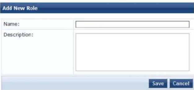
3. Define the Add New Role parameters as described in the following table, then click Save.
Table 135: Add New Role Page Parameters
| Parameter | Action/Description |
| Name Enter | the name of the role. |
| Description | Optionally, enter the description that provides additional information about the new role (recommended). |
Adding and Modifying Role-Mapping Policies
This section includes the following information:
- Adding a Role-Mapping Policy
- Mapping Rules
• Modifying a Role-Mapping Policy
Adding a Role-Mapping Policy
To add a role-mapping policy:
- Navigate to the Configuration > Identity > Role Mappings page.
The Role Mappings page opens:
Figure 232: Role Mappings Page
![Configuration » Identity » Role Mappings Role Mappings Filter: Name ▼ contains ▼ Go Clear Filter Show 10 records Name ▲ Description Default Role 1. [AirGroup Version Match] System-defined mapping to identify the protocol version of an AirGroup request [AirGroup v1] 2. Automation_Rolemapping eTIP5_Guest 3. Auto_Rolemapping_4_UnknownClient eTIP5_Guest 4. AUTO_SHL_MAPPING eTIP5_Guest 5. Device-Type-Role-Mapping Computer 6. [Guest Roles] The roles used by Guest: [Employee] 7. Onboard Authorization Maps RADIUS authorization attributes to a role for the Onboard device type [Guest] 8. rajesh-role Aruba-AP 9. [SMU]AD-Account-Exist Aruba-AP 10. [SMU] Switch Management TACACS role mapping [Other] Showing 1-10 of 15 ➤ Copy Export Delete](/content/2026/05/842116/images/e34981d5c1e3def5466825338a9cbf43a66df6ca807597d95e2de4211ba1e99c.jpg)
2. Click Add.
The Add Role-Mappings page opens to the Policy tab.
The Policy tab labels the method and defines the default role. The default role is the role to which Policy Manager defaults if the role-mapping policy does not produce a match for a given request.
Figure 233: Role Mappings > Policy Tab
![Configuration » Identity » Role Mappings » Add Role Mappings Policy Mapping Rules Summary Policy Name: Description: Default Role: [Contractor] View Details Modify Add new Role Back to Role Mappings Next > Save Cancel](/content/2026/05/842116/images/1c23a27a6994da6276bbe731c64e7965dc713c81a44cdb517101ffc5d9377b8d.jpg)
- Specify the Role Mappings > Policy parameters as described in the following table:
Table 136: Role Mappings > Policy Parameters
| Parameter | Action/Description |
| Policy Name | Enter the name of the role-mapping policy. |
| Description | Enter the description that provides additional information about the role mapping policy. |
| Default Role | Select the role to which Policy Manager will default when the role-mapping policy does not p a match. |
| View Details | To view the details of the default role, click View Details. |
| Modify To modify the default role, click Modify. | |
| Add New Role | To add a new role, click Add New Role. |
Mapping Rules
The Mapping Rules tab selects the evaluation algorithm to add, edit, remove, and reorder rules (see Figure 234).
Figure 234: Role Mapping > Mapping Rules Page
![Policy Mapping Rules Summary Rules Evaluation Algorithm: Select first match Select all matches Role Mapping Rules: Conditions Role Name 1. (Authorization:[Admin User Repository]:Role_Name EQUALS ADMIN) [Contractor] OR (Authorization:[Admin User Repository]:Role_Name EQUALS SYSADMIN) 2. (Authentication:Status EQUALS Machine) [Contractor] OR (Authorization:[Admin User Repository]:Role_Name EQUALS ADMIN) Add Rule Move Up Move Down Edit Rule Remove Rule Back to Role Mappings Next > Save Cancel](/content/2026/05/842116/images/2896f90064df1cdf7aa065e0fcd1761e6d82856920c8b248ebd537c07a989f44.jpg)
To add a mapping rule:
- Click Add Rule.
The Rules Editor page opens.
Figure 235: Rules Editor Page
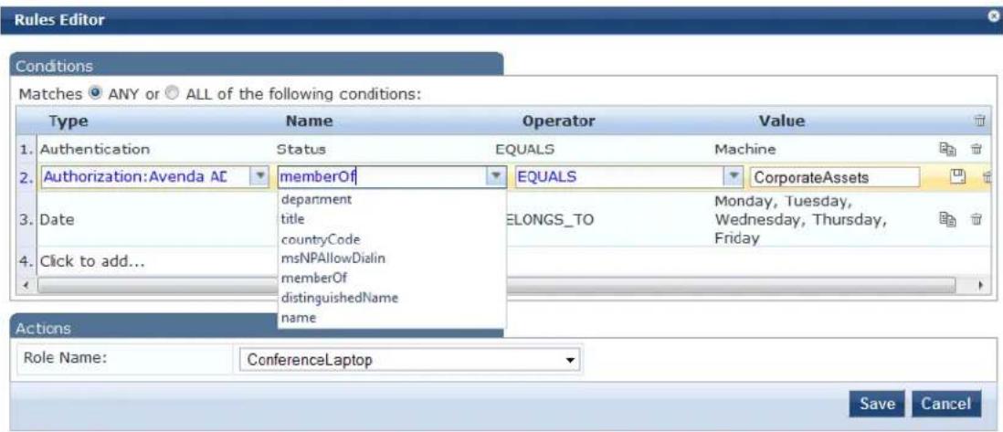
- Specify the Role Mappings Page > Rules Editor page parameters as described in the following table.
Table 137: Rules Editor Page Parameters
| Parameter Action/Description | |
| Type The Rules | Editor appears throughout the Policy Manager interface. It exposes different namespace dictionaries, depending on context. (Refer to Namespaces on page 919.)In the role mapping context, Policy Manager allows attributes from following namespaces:ApplicationApplication:ClearPassApplication:SSOAuthenticationAuthorizationAuthorization:: Policy Manager shows each instance of the authorization source for which attributes have been configured to be fetched (see Adding and Configuring Authentication Sources on page 207). Only those attributes that have been configured to be fetched are shown in the attributes drop-down list.CertificateConnectionDateDeviceEndpointGuestUserHostLocalUserOnboardTACACSRADIUS: All enabled RADIUS vendor dictionaries. |
| Name Displays | the drop-down list of attributes present in the selected namespace. |
| Operator Displays | the drop-down list of context-appropriate (with respect to the attribute data type) operators. For more information about operators, seeOperators on page 930. |
| Value Depending | on attribute data type, this may be a free-form (one or many line) edit box, a drop-down list, or a time/date widget. |
The operator values that display for each type and name are based on the data type specified for the authentication source (from the Configuration > Authentication > Sources page). If, for example, you modify the UserDN Data type on the authentication sources page to be an integer rather than a string, then the list of operator values here will populate with values that are specific to integers.
Modifying a Role-Mapping Policy
After you save your role-mapping configuration, it is displayed in the Mapping Rules list.
To modify a role-mapping policy:
- Select the rule you wish to modify.
- Then you can move the rule up or down in the list, edit the rule, or remove the rule.
- Click Save.

This chapter provides the following information:
• Posture Architecture and Flow
- Creating a New Posture Policy
- Configuring Posture Policy Agents and Hosts
- Configuring Posture Policy Plug-ins
- Configuring Posture Policy Rules
- Configuring Posture for Services
- Configuring Audit Servers
• Unified Agent System Tray Status Icons
Posture Architecture and Flow
This section provides the following information:
- Posture Policy
- Audit Servers
• Assessing Client Consistency
• Application Token - System Token
Policy Manager supports two types of posture checking: posture policies and audit servers.
Posture Policy
Policy Manager supports four pre-configured posture plug-ins for Windows, one plug-in®, found like plug-in for Mac OS, against which administrators can configure rules that test for specific attributes of cl health and correlate the results to return application posture tokens for processing by enforcement policy
A service can also be configured without any posture policy.
Audit Servers
Audit servers provide posture checking for unmanageable devices, such as devices lacking adequate post agents or supplicants. In the case of such clients, the audit server's post-audit rules map clients to roles Policy Manager supports two types of audit servers:
• NMAP audit server: Primarily used to derive roles from post-audit rules.
- NESSUS audit server: Primarily used for vulnerability scans (and, optionally, post-audit rules).

Figure 236: Posture Evaluation Process
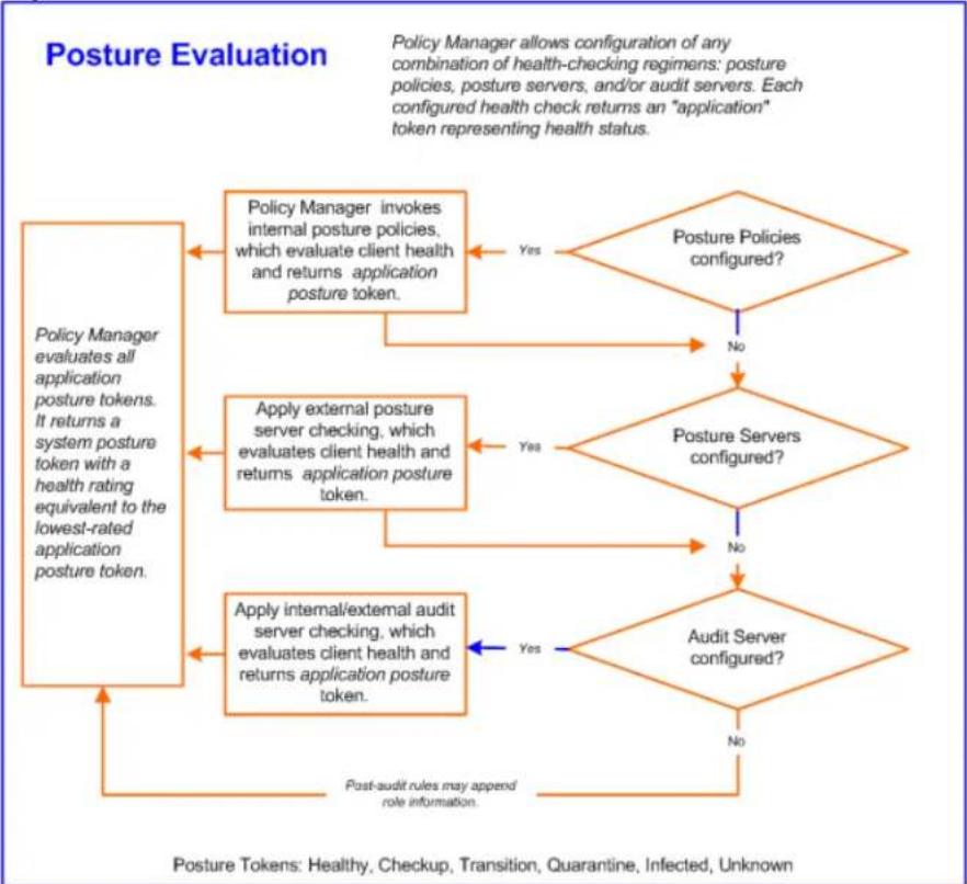
flowchart
graph TD
    A["Policy Manager evaluates all application posture tokens. It returns a system posture token with a health rating equivalent to the lowest-rated application posture token."] --> B{Policy Manager invokes internal posture policies, which evaluate client health and returns application posture token.}
    B -->|Yes| C{Posture Policies configured?}
    B -->|No| D{Apply external posture server checking, which evaluates client health and returns application posture token.}
    D -->|Yes| E{Posture Servers configured?}
    D -->|No| F{Apply internal/external audit server checking, which evaluates client health and returns application posture token.}
    F -->|Yes| G{Audit Server configured?}
    F -->|No| H["Post-Audit rules may append role information."]
    C --> I["Posture Policies configured?"]
    E --> I
    G --> I
    H --> I
    style A fill:#f9f,stroke:#333
    style I fill:#f9f,stroke:#333
Assessing Client Consistency
W-ClearPass Policy Manager uses posture evaluation to assess client consistency with enterprise endpoint health policies, specifically with respect to:
- Operating system version/type
• Registry keys/services present (or absent)
• Antivirus/antispyware/firewall configuration - Patch level of software components
• Peer-to-Peer (P2P) application checks
• Services to be running or not running
• Processes to be running or not running
Application Token
Each configured health check returns an application token representing health:
• Healthy. Client is compliant: there are no restrictions on network access.
- Checkup. Client is compliant; however, there is an update available. This can be used to proactively remediate to healthy state.
- Transient. Client evaluation is in progress; typically associated with auditing a client. The network access granted is interim.
- Quarantine. Client is out of compliance; restrict network access so the client only has access to the remediation servers.
- Infected. Client is infected and is a threat to other systems in the network; network access should be denied or severely restricted.
- Unknown. The posture token of the client is unknown.
System Token
Upon completion of all configured posture checks, Policy Manager evaluates all application tokens and calculates a system token, equivalent to the most restrictive rating for all returned application tokens. The system token provides the health posture component for input to the enforcement policy.
Unified Agent System Tray Status Icons
This section provides the following information:
• About the Unified Agent
• Unified Agent System Tray Icons
• OnGuard-Only System Tray Icons
About the Unified Agent
W-ClearPass Onguard agent is integrated with Dell VIA (Virtual Internet Adapter) to support both VIA functionality and Onguard agent system health status collection. Thus, the integrated product is the called Unified Agent.
NAP (Network Access Protection) is a framework to collect system health status on Microsoft clients.
W-ClearPass supports health status collection for both NAP and OnGuard.
The Unified Agent System Tray icons display the following states of the Unified Agent status:
- OnGuard health status
- Trusted or untrusted network status
• VPN connectivity status - Error conditions
Unified Agent System Tray Icons
Table 138 describes that icons that indicate the possible states for the Unified Agent.
Table 138: Unified Agent System Tray Icons
| OnGuard Status | Network Type | VPN Status | Icon |
| Healthy | Trusted | Connected |  |
| Healthy | Trusted | Disconnected |  |
| Unhealthy | Trusted | Connected |  |
| Unhealthy | Trusted | Disconnected |  |
| Healthy | Untrusted | Connected |  |
| Healthy | Untrusted | Disconnected |  |
| Unhealthy | Untrusted | Connected |  |
| Unhealthy | Untrusted | Disconnected | [YSA4] |
| Healthy | N/A | Error |  |
| Unhealthy | N/A | Error |  |
| Logged Out: No Health Status | N/A | Error | [2DB2] |
| Error | Trusted | Connected | [BYK2] |
| Error | Trusted | Disconnected |  |
| Error | Untrusted | Connected | [3BWA] |
| Error | Untrusted | Disconnected |  |
| Error | No Profile | N/A |  |
| Error | N/A | Error |  |
| Healthy | No Profile | N/A |  |
| Unhealthy | No Profile | N/A |  |
| Logged Out: No Health Status | No Profile | N/A |  |
| Logged Out: No Health Status | Trusted | Connected |  |
| Logged Out: No Health Status | Untrusted | Disconnected |  |
OnGuard-Only System Tray Icons
Table 139 describes that icons that indicate the possible states for OnGuard-only.
Table 139: OnGuard-Only System Tray Icons
| OnGuard Status | Network Type | VPN Status | Icon |
| Healthy | N/A | N/A |  |
| Unhealthy | N/A | N/A |  |
| Logged Out: No Health Status | N/A | N/A |  |
| Error | N/A | N/A |  |
Creating a New Posture Policy
This chapter provides the following information:
• About W-ClearPass Posture Policies
- Creating a New Posture Policy
About W-ClearPass Posture Policies
W-ClearPass Policy Manager evaluates the health of the clients that request access using posture policies an audit server.
All these methods return posture tokens (for example, Healthy and Quarantine) for used by Policy Management input into an enforcement policy. You can associate one or more posture methods with a single service.
W-ClearPass Policy Manager forwards all or part of the posture data received from the client to a postur server. Nmap (Network Mapper) or Nessus audit servers provide posture checking for unmanageable devi
such as devices lacking adequate posture agents or supplicants. For more information on audit servers, s Configuring Audit Servers on page 355.
Creating a New Posture Policy
From the Posture Policies page, you can create a new policy or edit an existing policy.
To create a new posture policy:
- Navigate to Configuration > Posture > Posture Policies.
The Posture Policies page displays a list of all existing posture policies.
Figure 237: Posture Policies Page
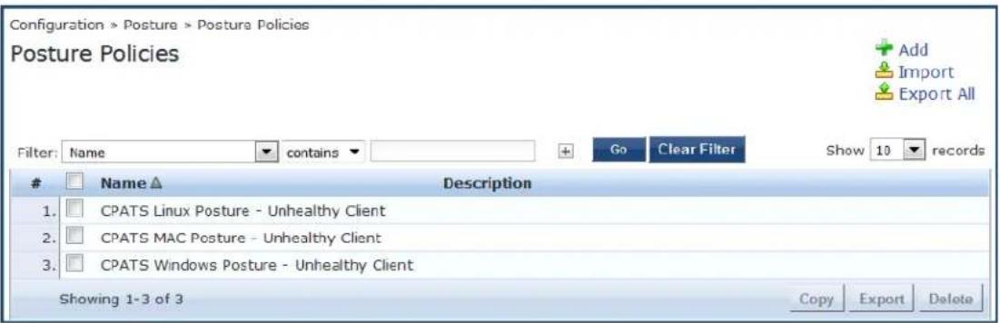
- Click the Add link.
The Add Posture Policies configuration dialog opens.
Figure 238: Add Posture Policies Configuration Dialog
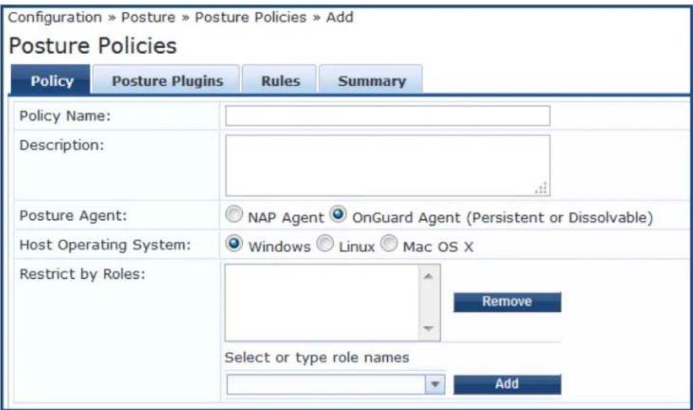
-
Configure the information in the Add Posture Policies page as described in Configuring Posture Policy Agents and Hosts on page 285.
-
For information on configuring the posture policy plug-ins, see Configuring Posture Policy Plug-ins on page 288.
■ For information on configuring posture policy rules, see Configuring Posture Policy Rules on page 352.
Configuring Posture Policy Agents and Hosts
This section provides the following information:
- Introduction
• NAP Agent Posture Plug-ins - OnGuard Agent Posture Plug-ins
Introduction
To configure posture policy agents and hosts:
- Navigate to Configuration > Posture > Posture Policies.
The Posture Policies page displays a list of all existing posture policies.
Figure 239: Posture Policies Page
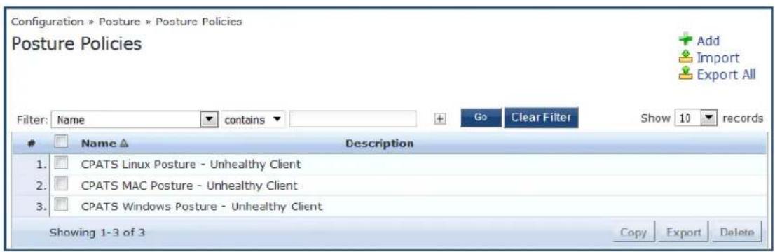
- Click the Add link.
The Add Posture Policies page opens.
Figure 240: Add Posture Policies Page
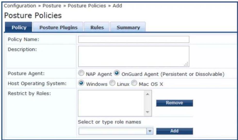
- Use the Posture Policies > Policy dialog to configure the policy name and description, select a posture agent and host operating system, and specify role restrictions.
Specify the Add Posture Policy parameters as described in the following table:
Table 140: Add Posture Policy Parameters
| Parameter Action/Description | |
| Policy Name 1. Enter the name assigned to the policy by the W-ClearPass Policy Manager administrator. | |
| Description 2. Specify the description that provides additional information about the posture policy. | |
| Posture Agent 3. Select the posture agent type.For detailed information on these agents, see NAP Agent Posture Plug-ins on page 286 and OnGuard Agent Posture Plug-ins on page 286. | |
| Host Operating System | 4. Specify whether the host is using a Windows, Linux, or MAC OS X operating system. |
| Restrict by Roles | 5. Apply the posture policy to the selected roles. |
NAP Agent Posture Plug-ins
When you select NAP Agent as the Posture agent, you can configure the posture plug-ins as described in Table 141:
Table 141: NAP Agent: Windows OS Posture Plug-ins Support
| Plug-in | Description | Windows Support |
| Windows System Health Validator | The Windows System Health Validator permits or denies client computers to connect to your network. The Windows System Health Validator also restricts client access to computers that have a service pack less than service pack x. | Windows 10: YesWindows 8: YesWindows 7: YesWindows Vista: YesWindows XP Svc Pack 3: YesWindows Server 2008, 2008R2: YesWindows Server 2012, 2012R2: Yes |
| Windows Security Health Validator | The Windows Security Health Validator permits or denies client computers access to your network, subject to checks of the client's system for Firewall, Virus Protection, Spyware Protection, Automatic Updates, and Security Updates.NOTE: If you configure the Windows Security Health Validator posture plugin for Windows XP, spyware protection is disabled. | Windows 10: YesWindows 8: YesWindows 7: YesWindows Vista: YesWindows XP Svc Pack 3: YesWindows Server 2008, 2008R2: NoWindows Server 2012, 2012R2: No |
OnGuard Agent Posture Plug-ins
Select OnGuard Agent (Persistent or Dissolvable) as the Posture Agent for use in the following scenarios:
- An environment that does not support 802.1X-based authentication. For example, some legacy Microsoft Windows operating systems or legacy network devices.
- An environment configured with an operating system that provides support for 802.1X natively, but does not have a built-in health agent. Macintosh OS X is an example of this type of environment.
When you select the Posture Agent: OnGuard Agent (Persistent or Dissolvable), you can configure the posture plug-ins for:
• Windows (see Table 142)
• Macintosh OS X (see Table 143)
• Linux (see Table 144)
Table 142: OnGuard Agent Validator Posture Plug-in Windows OS Support
| Plug-in Description | Windows Support | |
| W-ClearPassWindows Universal System Health Validator | The configurable parameter categories for this validator are: Services, Processes, Registry Keys, AntiVirus, AntiSpyware, Firewall, Peer To Peer, Patch Management, Windows HotFixes, USB Devices, Virtual Machines, Network Connections, Disk Encryption, Installed Applications, and File Check. | ● Windows 10: Yes● Windows 8: Yes● Windows 7: Yes● Windows Vista: Yes● Windows 2003: Yes● Windows XP Svc Pack 3: Yes● Windows Server 2008, 2008R2: YesNOTE: Configuration for Windows Server 2008 applies also to Windows Server 2008R2.● Windows Server 2012, 2012R2: YesNOTE: Configuration for Windows Server 2012 applies also to Windows Server 2012R2. |
| Windows System Health Validator | The Windows System Health Validator allows you to configure client computers that can connect to your network, and clients that are restricted from your network. Access is determined by a check of the service pack level. You can determine the service pack level. | ● Windows 10: Yes● Windows 8: Yes● Windows 7: Yes● Windows Vista: Yes● Windows 2003: Yes● Windows XP Svc Pack 3: Yes● Windows Server 2008, 2008R2: Yes● Windows Server 2012, 2012R2: Yes |
| Windows Security Health Validator | The configurable parameter categories for this validator allow you to configure parameters that permit or deny client computers access to your network, subject to checks of the client's system for Firewall, Virus Protection, Spyware Protection, Automatic Updates, and Security Updates.NOTE: If you configure the posture plug-in for Windows XP, spyware protection is disabled. | ● Windows 10: Yes● Windows 8: Yes● Windows 7: Yes● Windows Vista: Yes● Windows 2003: No● Windows XP Svc Pack 3: Yes● Windows Server 2008, 2008R2: No● Windows Server 2012, 2012R2: No |
Table 143: OnGuard Agent (Persistent or Dissolvable) Posture Plug-ins for Mac OS X
| Plug-in Description | |
| W-ClearPass Macintosh OS X Universal System Health Validator | The configurable parameter categories for this validator are:■ Services■ Processes■ AntiVirus■ AntiSpyware■ Firewall■ Patch Management■ Peer-to-Peer■ USB Devices■ Virtual Machines■ Network Connections■ Disk Encryption■ Installed Applications■ File Check |
Table 144: OnGuard Agent (Persistent or Dissolvable) Posture Plug-ins for Linux
| Name of the Plug-in Description | |
| W-ClearPass Linux Universal System Health Validator | The configurable parameter categories for this validator are:■ Services■ AntiVirus |
Configuring Posture Policy Plug-ins
The Posture Plugins dialog of the Posture Policies page allows you to configure plug-ins for the posture policy. The plug-ins available on this tab vary, depending upon whether the policy is using a Network Ac Protection (NAP) agent or the OnGuard Agent (Persistent or Dissolvable) plug-in.
To configure posture policy plug-ins:
- Navigate to Configuration > Posture > Posture Policies.
The Posture Policies page appears.
Figure 241: Posture Policies Page
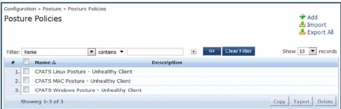
- Click Add.
The Add Posture Policies page appears.
- In the Policy tab, specify the following:
■ Policy Name
■ Description
■ Posture Agent
■ Host Operating System
- Select the Posture Plugins tab .
The Add Posture Plugins page appears.
Figure 242: Add Posture Plugins Page

You can configure the following posture plug-ins in the Posture Policies page:
-
ClearPass Windows Universal System Health Validator > OnGuard Agent on page 289
■ Windows System Health Validator: NAP Agent on page 349
■ Windows System Health Validator: OnGuard Agent on page 328
■ Windows Security Health Validator: NAP Agent on page 350 -
Select the check box of the plug-in you wish to configure.
- To view the configuration page for the selected plug-in, click Configure.
Configuring OnGuard Agent Plugins
If you select the OnGuard Agent option in the Policy tab of the Posture Policies page, the Posture Plugins tab allows you to configure different plugin types for hosts running Windows, Linux, and Mac OS X oper systems. Refer to the following topics for details on each plugin type:
- For Windows:
-
ClearPass Windows Universal System Health Validator > OnGuard Agent on page 289
■ Windows System Health Validator: OnGuard Agent on page 328
■ Windows Security Health Validator: OnGuard Agent on page 329 -
For Linux: W-ClearPass Linux Universal System Health Validator Plugin on page 330
• For Mac OSX: W-ClearPass Macintosh OS X Universal System Health Validator: OnGuard Agent on page 333
The following figure displays the Posture Policies - Posture Plugins tab:
Figure 243: OnGuard Agent Plugin Options for Mac OS X
Configuration » Posture » Posture Policies » Add
Posture Policies

ClearPass Windows Universal System Health Validator > OnGuard Agent
To configure the W-ClearPass Windows Universal Health System Health Validator (OnGuard Agent):
- Navigate to Configuration > Posture > Posture Policies, then click Add.
The Add Posture Policies dialog opens.
Figure 244: Adding a Posture Policy
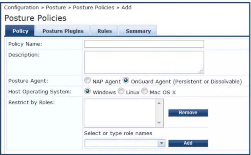
a. Enter the name and a description of the posture policy.
b. Posture Agent: Choose OnGuard Agent (Persistent or Dissolvable).
c. Host Operating System: Windows is selected by default.
d. Click Next.
The Posture Plugins dialog opens.
Figure 245: Selecting the Windows Posture Plugin
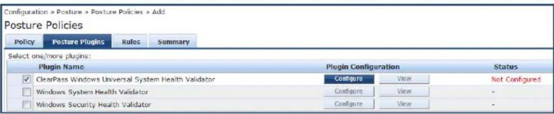
- In the Posture Plugins page, click the check box for ClearPass Windows Universal System Health Validator.
- Click Configure.
The ClearPass Windows Universal System Health Validator page opens.
- Select the desired version of Windows.
- To enable checks for the selected version, click the Enable checks for Windows Server check box.
Figure 246: ClearPass Windows Universal System Health Validator Page
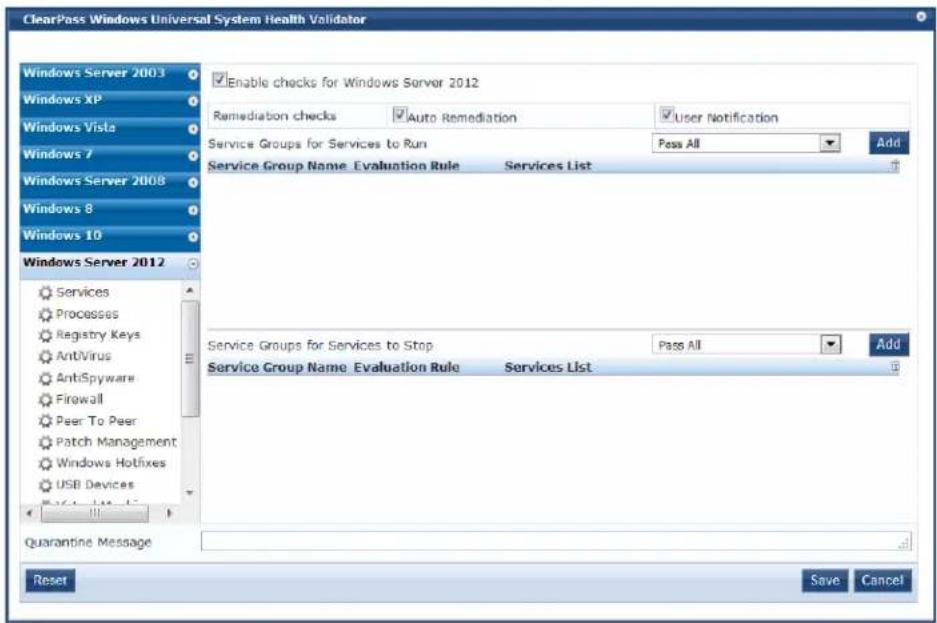
The following list of configuration pages for the selected version of Windows appears (see Figure 246):
• Services on page 291
• Processes on page 296
• Registry Keys on page 299
• AntiVirus on page 302
• AntiSpyware on page 304
- Firewall on page 305
• Peer To Peer on page 307
- Patch Management on page 308
• Windows Hotfixes on page 312
• USB Devices on page 317
• Virtual Machines on page 317
• Network Connections on page 318
• Disk Encryption on page 320
• Installed Applications on page 321
• File Check on page 324
- When finished, click Save.
Services
The Service feature allows network admins to determine how the overall health status of the Services health class is determined—whether by using an AND condition (for example, Group1 AND Group2) or an OR condition (for example, Group1 OR Group2).
Regarding services, for example, admins can run checks such as Service1 AND Service2 OR Service3 AND Service4. You can also use the Services page to verify the group of services to be present or absent and specify the service groups and services to run on a client.
To define Windows Service Groups, specify the evaluation rules, and add or remove specific Windows server on the endpoint:
- Navigate to Configuration > Posture > Posture Policies, then click Add.
- From the Add Posture Policies page, select the Posture Plugins tab.
- Select the W-ClearPass Windows Universal System Health Validator, then click Configure.
- Select the Windows operating system, then check the Enable checks for Windows_OS.
- Select Services.
The Services health class configuration page opens:
Figure 247 displays an example of the W-ClearPass Widows Universal System Health Validator > Services configuration page and highlights examples of the evaluation rule for groups and the evaluation rule for services:
Figure 247: Specifying Service Groups to Run
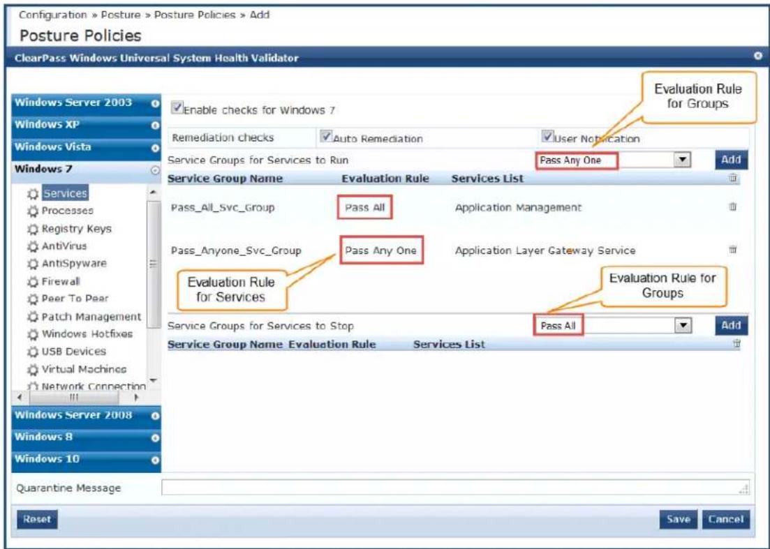
- Specify the W-ClearPass Widows Universal System Health Validator > Services configuration parameters as described in the following table:
Table 145: Services Configuration Parameters
| Parameter Action/Description | |
| Auto Remediation Enable | to allow auto-remediation for service checks. Enabling this option automatically stops or starts services based on the entries inService to RunandServices to Stop configuration.Auto-remediation for theServiceshealth class is enabled by default. |
| User Notification When enabled, a remediation message that includes the groups of services to be present or absent is displayed to the end user. | |
Defining the Service Group to Be Present
You can configure the name of the service group and specify the evaluation rule for the service group.
1. To configure the Service Groups for Services to Run, click Add.
The Add Service Group to Be Present dialog opens.
Figure 248: Specifying the Service Group Evaluation Rule
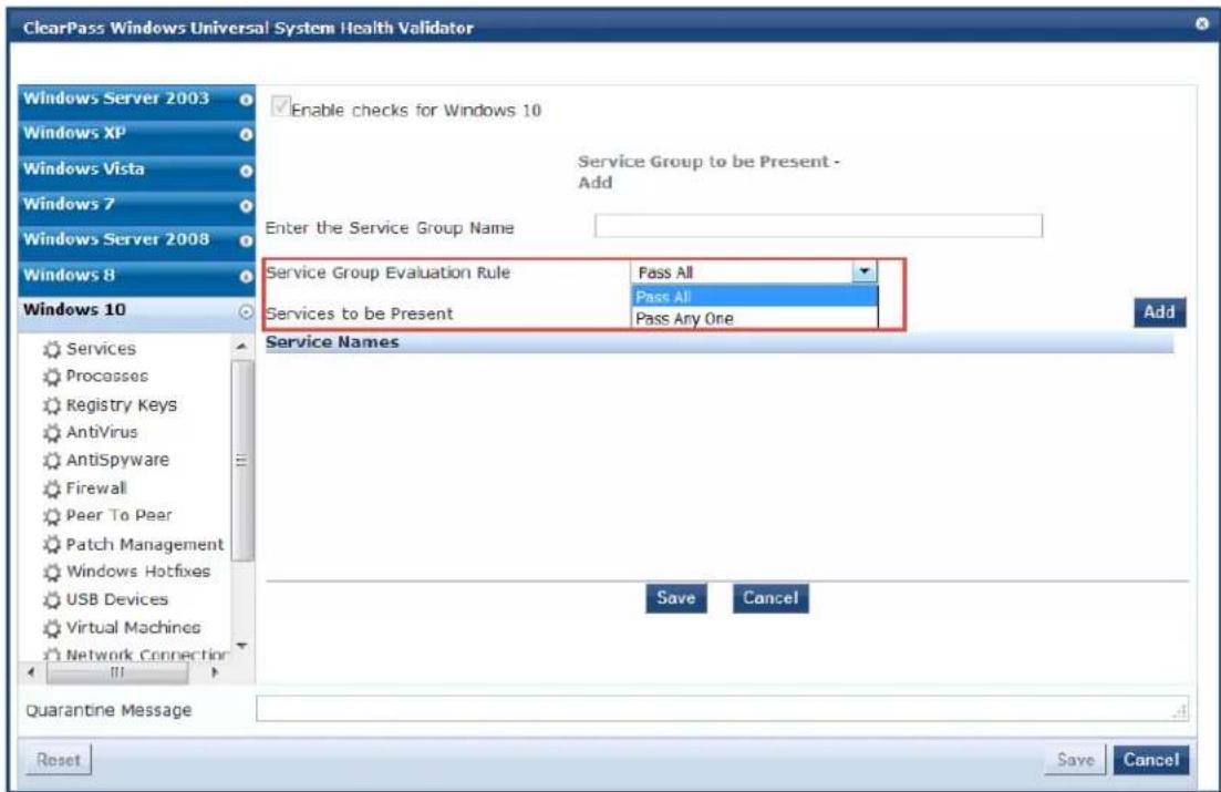
2. Specify the Add Service Group to Be Present parameters as described in the following table:
Table 146: Add Service Group to Be Present Parameters
| Parameter Action/Description | |
| Enter the Service Group Name | 1. Enter the name of the Service Group. |
| Service Group Evaluation Rule | 2. Select the appropriate Service Group Evaluation Rule:Pass All: Select this evaluation rule if you want the Services health class to be deemed as healthy only if all the configured service groups are present.Pass All is the equivalent of an AND condition.Pass Any One: Select this evaluation rule if you want the Services Check health class to be deemed as healthy even if any one of the configured service gro present.Pass Any One is the equivalent of an OR condition. |
Specifying the Services to Be Present
To specify the services to be present:
1. Click the Services to Be Present > Add button.
The Add Services to Run dialog opens.
Figure 249: Specifying the Services to Run
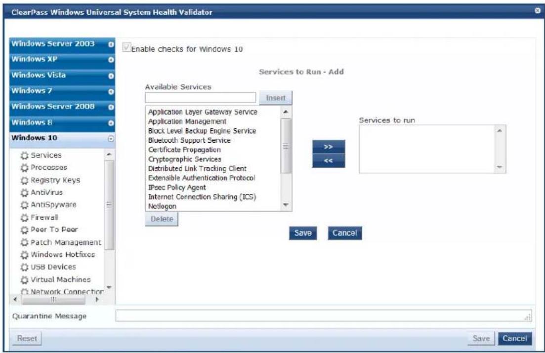
- Select one or more of the desired services from the Available Services list.
- To move the desired services to the Services to Run box, click >>, then click Save.
- You can also add a service to the list of available services. To do so, enter the service name in the box, then click Insert.
Defining the Service Group to Be Absent
You can configure the name of the service group and specify the evaluation rule for the service group.
- To configure the Service Groups for Services to Be Absent, click Add.
The Add Service Group to Be Absent dialog opens.
Figure 250: Add Services to Be Absent Dialog
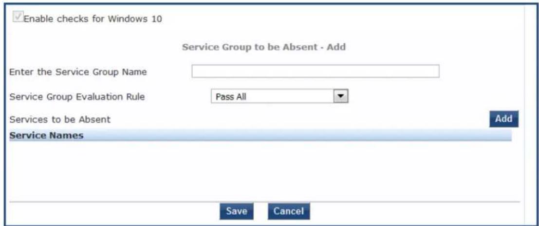
- Specify the Service Groups to Be Absent parameters as described in the following table:
Table 147: Add Service Group to Be Absent Parameters
| Parameter Action/Description | |
| Enter the Service Group Name | 1. Enter the name of the Service Group. |
| Service Group Evaluation Rule | 2. Select the appropriate Service Group Evaluation Rule:Pass All: Select this evaluation rule if you want all service groups to be stopped.Pass All is the equivalent of an AND condition.Pass Any One: Select this evaluation rule if you want any one of the service groups to be stopped.Pass Any One is the equivalent of an OR condition. |
3. Click Add.
The Add Services to Stop dialog opens.
Figure 251: Specifying the Services to Stop
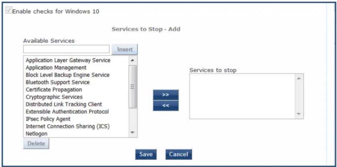
- Select one or more of the desired services from the Available Services list.
- To move the desired services to the Services to Stop box, select the desired services, then click >>.
a. To remove services from the Services to Stop box, select the services to be removed, then click <<.
- When finished configuring the services to stop, click Save.
Figure 252 shows an example of services configured for Windows Server 2003.
Figure 252: Example of Services Configured
| ✓Enable checks for Windows Server 2003 | |||
| Remediation checks | ✓Auto Remediation | ✓User Notification | |
| Service Groups for Services to Run | Pass All | Add | |
| Service Group Name Evaluation Rule Services List | |||
| Service-Grp-1-Run-All-services Pass All | DHCP Client, File Replication, Indexing Service | ||
| Service-GRP-2-Run-Anyone Pass Any One | Indexing Service, Performance Logs and Alerts, Smart Card | ||
| Service Groups for Services to Stop | Pass Any One | Add | |
| Service-Stop-all-1 Pass All | Messenger, Performance Logs and Alerts, Remote Registry, Routing and Remote Access, Smart Card | ||
| Service-stop-anyone Pass Any One | Indexing Service, Messenger, Performance Logs and Alerts, Remote Registry, Routing and Remote Access, Smart Card | ||
Processes
The Processes page provides a set of parameters to specify which processes to be explicitly present or absent on the system.
To configure Processes:
- Navigate to Configuration > Posture > Posture Policies, then click Add.
- From the Add Posture Policies page, select the Posture Plugins tab.
- Select the W-ClearPass Windows Universal System Health Validator, then click Configure.
- Select the Windows operating system, then check the Enable checks for Windows_OS.
- Select Processes.
The Processes health class configuration page opens:
Figure 253: Processes Configuration Page
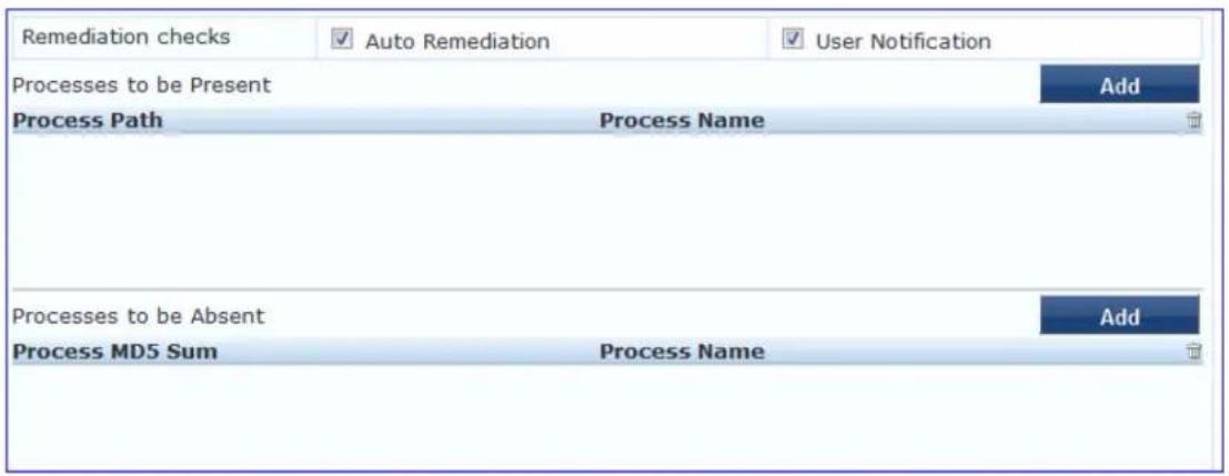
- Specify the Processes configuration parameters as described in the following table:
Table 148: Processes Page Parameters
| Parameter Action/Description | |
| Auto Remediation 1. | Enable to allow auto-remediation for processes. |
| User Notification 2. | Enable to allow user notifications in the event of process policy violations. |
Processes to be Present Parameters
- In the Processes to be Present section, click Add.
The Add Processes to be Present page opens.
Figure 254: Add Processes to be Present Page
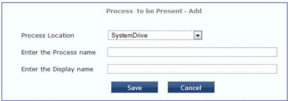
- Specify the Processes to be Present parameters as described in the following table, then click Save:
Table 149: Processes to be Present Page Parameters
| Parameter Action/Description | |
| Process Location 1. Choose from the following locations:System DriveSystemrootProgram FilesHOMEDRIVEHOMEPATHNone | |
| Enter the Process name | 2. Specify the path name containing the process executable name. |
| Enter the Display name | 3. Enter a user-friendly name for the process. This is displayed in end-user facing messages. |
After you save the Processes parameters, the information appears in the Processes to be Present section.
Processes to be Absent Parameters
- In the Processes to be Absent section, click Add.
The Add Processes to be Absent page opens.
Figure 255 shows the configuration parameters for when you select Process Name and when you select MD5 Sum.
Figure 255: Process to be Absent Pages: Process Name and MD5 Sum
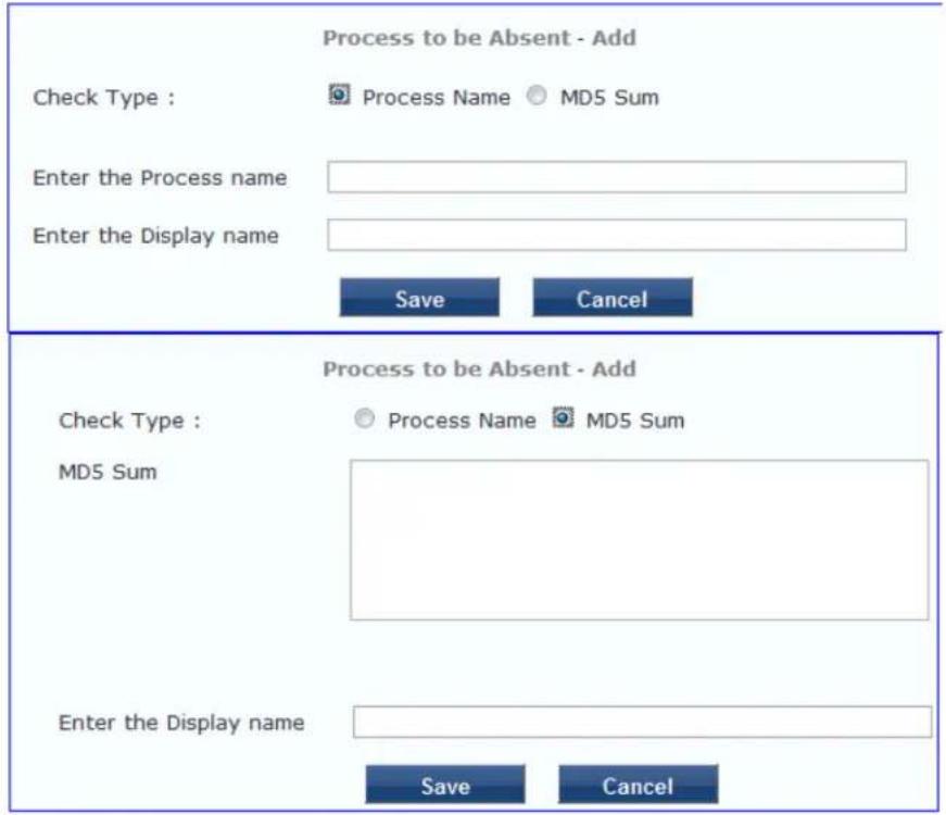
- Specify the Processes to be Absent parameters as described in the following table, then click Save:
Table 150: Processes to be Absent Page Parameters
| Parameter | Action/Description |
| Check Type | 1. Select the type of process check to perform. The agent can look for the following:■Process Name:The agent looks for all processes that matches with the given name.For example, if notepad.exe is specified, the agent kills all processes whose name matches, regardless of the location from which these processes were started.■MD5 Sum:This specifies one or more (comma-separated) MD5 checksums of the process executable file.For example, if there are multiple versions of the process executable, you can specify the MD5 sums of all versions here.The agent enumerates all running processes on the system, computes the MD5 sum of the process executable file, and matches this with the specified list. One or more of the matching processes are then terminated. |
| Enter the Display name | 2. Enter a user-friendly name for the process. This display name is displayed in end-user facing messages. |
You return to the Processes Configuration page, which now shows the values for the processes that were configured:
Figure 256: Processes Configured
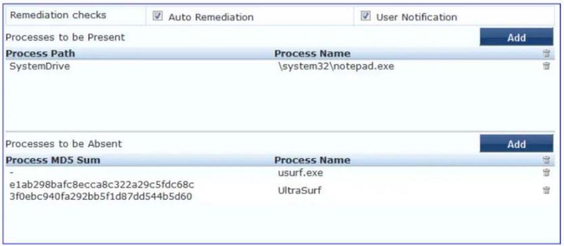
Registry Keys
The Registry Keys page allows you to specify which registry keys are to be explicitly present or absent.
To define the registry keys:
- Navigate to Configuration > Posture > Posture Policies, then click Add.
- From the Add Posture Policies page, select the Posture Plugins tab.
- Select the W-ClearPass Windows Universal System Health Validator, then click Configure.
- Select the Windows operating system, then check the Enable checks for Windows_OS.
- Select Registry Keys.
The Registry Keys health class configuration page opens:
Figure 257: Registry Keys Page (Overview)
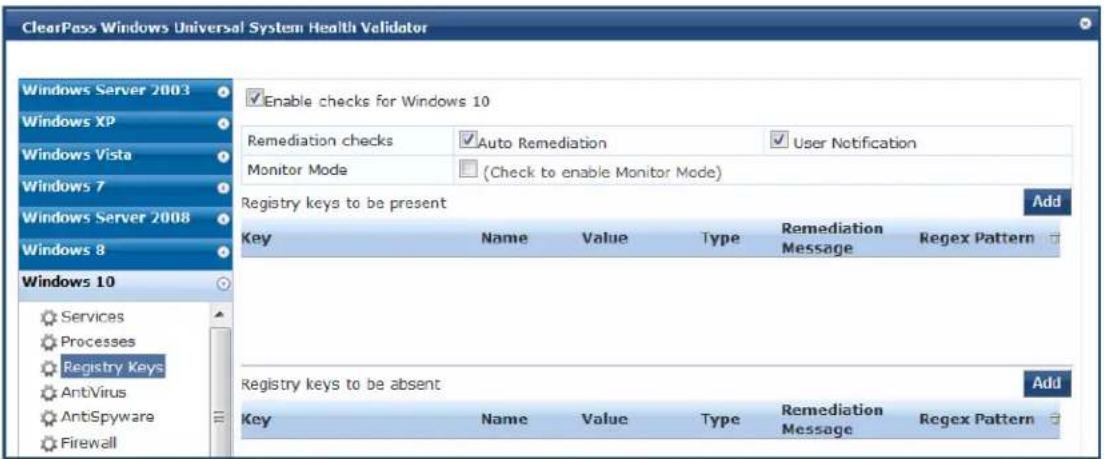
- Specify the Registry Keys page parameters as described in the following table:
Table 151: Registry Keys Page Parameters
| Parameter Action/Description | |
| Auto Remediation | 1. Enable auto remediation for registry checks.Use this page to automatically add or remove registry keys based on the entries in Registry keys to be present and Registry keys to be absent fields. |
| User Notification | 2. Enable user notifications for registry check policy violations. |
| Monitor Mode | 3. Enable this to set the health status of the Registry Keys health class healthy.This allows administrators to collect information related to missing registry keys without marking the clients as unhealthy even if some registry keys are missing. |
| Registry keys to be present | 4. To specify a registry key to be added to the Registry keys to be present list, click Add.If the specified registry key is not present, the remediation message that is added in the Registry Keys Page (Detail) window is displayed on OnGuard Agent. |
| Registry keys to be absent | 5. To add a registry key to the Registry keys to be absent list, click Add.If the specified registry key is not absent, the remediation message that is added in the Registry Keys Page (Detail) window is displayed on OnGuard Agent. |
- To configure the Registry key to Be Present, click Add.
The Edit Registry Key to Be Present dialog opens.
Figure 258: Edit Registry Keys to Be Present Parameters
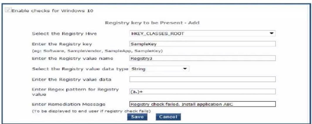
- Specify the Registry Key to be Present parameters as described in Table 152, then click Save.
Table 152: Registry Keys Page (Detail)
| Parameter Action/Description | |
| Select the Registry Hive | 1. Specify the registry hive from the following options:■ HKEY_CLASSES_ROOT■ HKEY_CURRENT_USER■ HKEY_LOCAL_MACHINE■ HKEY_USERS■ HKEY_CURRENT_CONFIG |
| Enter the Registry key | 2. Specify the registry key using the examples given in the GUI. |
| Enter the Registry value name | 3. Specify the name of the registry value. |
| Select the Registry value data type | 4. Specify the registry value data types. The data type can be any of the following:■ Multi String■ String■ DWORD■ QWORD■ Expandable String |
| Enter the Registry value data | 5. Specify the registry value. |
| Enter Regex pattern for Registry value | 6. Enter the Regular Expression (Regex) pattern for the Registry value.A regular expression is a pattern that the regular expression engine attempts to m input text. A pattern consists of one or more character literals, operators, or constNOTE: Perl regular expressions are supported. |
| Enter Remediation Message | 7. Specify the custom remediation message to be displayed to end users if the registry check fails. |
As shown in Figure 259, after you save the registry configuration settings, the remediation message and Regular Expression pattern appears in the Registry page.
Figure 259: Registry Keys Added
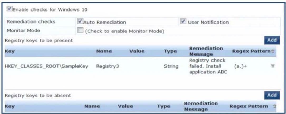
AntiVirus
In the Antivirus page, you can turn on an Antivirus application.
To define the Antivirus health class:
- Navigate to Configuration > Posture > Posture Policies, then click Add.
- From the Add Posture Policies page, select the Posture Plugins tab.
- Select the W-ClearPass Windows Universal System Health Validator, then click Configure.
- Select the Windows operating system, then check the Enable checks for Windows_OS.
- Select Antivirus.
The Antivirus health class configuration page opens:
Figure 260: Antivirus Page: Enabling Antivirus application

- Click An antivirus application is on to configure the Antivirus application information.
When enabled, the Antivirus detail page opens.
Figure 261: Antivirus Page: Remediation Checks
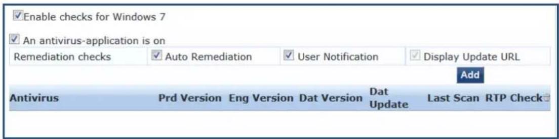
- To specify product and version-check information, click Add.
Figure 262: Antivirus Check Configuration Dialog
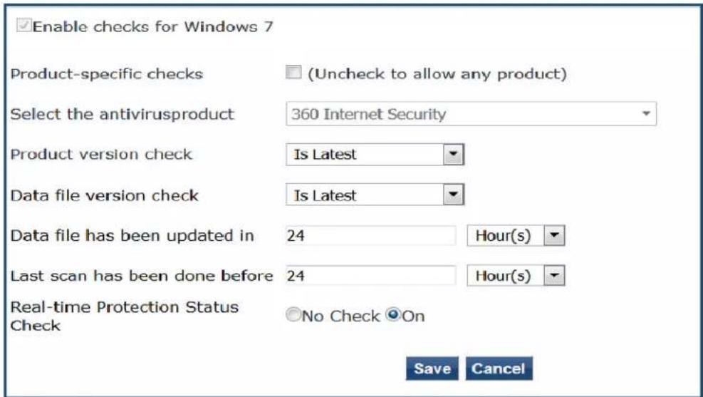
- Specify the Antivirus health class parameters as described in the following table:
Table 153: Antivirus Health Class Parameters
| Parameter Action/Description | |
| An Antivirus Application is On | ClickAntivirus application is onto enable testing of health data for configured Antivirus application(s). |
| Auto Remediation Check theAuto Remediationcheck box to enable auto remediation of anti-virus status. This option is enabled by default. | |
| User Notification | Check theUser Notificaticoncheck box to enable user notification of policy violation of anti-virus status. This option is enabled by default. |
| Display Update URL | Check theDisplay Update URLcheck box to show the origination URL of the update. This option is disabled by default. |
| Product-specific checks | To configure for product-specific checks, leave the check box checked (the default setting).To allow any Antivirus product, uncheck the check box.All of these checks may not be available for some products. Where checks are not available, they are shown in disabled state.. |
| Select the antivirus product Select an antivirus product from the drop-down list. | |
| Product version check Select one of the following options:No CheckIs Latest:Requires registration with W-ClearPass portal.In Last N Updates:Requires registration with W-ClearPass Portal. | |
| Datafile version check | Select one of the following options:No CheckIs Latest:Requires registration with W-ClearPass portal.In Last N Updates:Requires registration with W-ClearPass Portal. |
| Engine version check | NOTE:The Engine Version Checkoption is removed from the Antivirus health class in W-ClearPass Posture Policy configuration for plugin version 2.0 (SDK V4) for both Windows and Mac OS.When using plugin version 1.0 (SDK V3), select one of the following options:No CheckIs Latest:Requires registration with W-ClearPass portal.In Last N Updates:Requires registration with W-ClearPass Portal. |
| Data file has been updated in | Enter the number, then specify the interval in hours, days, weeks, or months. |
| Last scan has been done before | Enter the number, then specify the interval in hours, days, weeks, or months. |
| Real-time Protection Status Check | No Check: W-ClearPass does not use Real-time Protection status value for health evaluation. This means that the client is treated as healthy irrespective of the value of RTP.On: Marked as healthy only if the value of Real-time Protection status is On. |
After you save your Antivirus configuration, it is listed on the Antivirus page.
Figure 263: Antivirus Check Configured
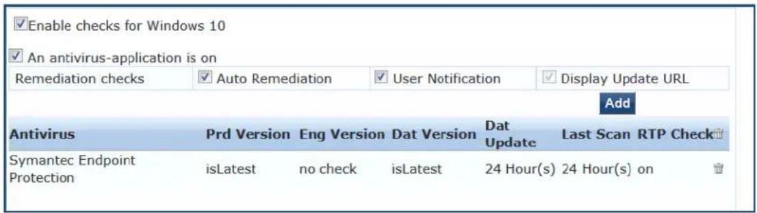
AntiSpyware
In the AntiSpyware page, an administrator can specify that an AntiSpyware application must be on. This page allows drill-down to specify information about the AntiSpyware application.
The AntiSpyware health class is not supported in the OnGuard Detection V4 SDK.
To define the Antivirus health class:
- Navigate to Configuration > Posture > Posture Policies, then click Add.
- From the Add Posture Policies page, select the Posture Plugins tab.
- Select the W-ClearPass Windows Universal System Health Validator, then click Configure.
- Select the Windows operating system, then check the Enable checks for Windows_OS.
- Select Antivirus.
The Antivirus health class configuration page opens:
Figure 264: AntiSpyware Page (Overview Before)

- To configure the AntiSpyware application information, click the An Antipyware Application is On check box.

When enabled, the AntiSpyware detail page opens.
Figure 265: AntiSpyware Page (Detail 1)

- To specify product and version check information, click Add.
Figure 266: AntiSpyware Page (Detail 2)
![Product-specific checks ✓ (Uncheck to allow any product) Select the antispyware product AVG Anti-Malware [AntiSpyware] Product version check Is Latest Engine version check Is Latest Data file version check No Check Data file has been updated in 2 Hour(s) Last scan has been done before Hour(s) Real-time Protection Status Check No Check On Off Save Cancel](/content/2026/05/842116/images/2f260994852166fec98297b9704e287146d49ce9c2b175a2df2e5129fe15e7d9.jpg)
- Specify the AntiSpyware parameters, then click Save.
Figure 267: AntiSpyware Page (Overview After)
![An antispyware application is on Remediation checks ✓ Auto Remediation ✓ User Notification ✓ Display Update URL Add Antispyware Prd Version Eng Version Dat Version Dat Update Last Scan Rtp Check AVG Anti-Malware [AntiSpyware] isLatest isLatest=no check 2 Hour(s)=no check=nocheck](/content/2026/05/842116/images/5a6b2ff1631c377d37c134986a9e2c10ff19b4c4cbbc2f17c98e63d60792bd23.jpg)
When you save your AntiSpyware configuration, it appears in the AntiSpyware page.
Firewall
In the Firewall page, you can specify that a Firewall application must be on and specify information about the Firewall application.
Figure 268: Firewall Page (Overview Before)

In the Firewall page, click A Firewall Application is On to configure the Firewall application information.
Figure 269: Firewall Page (Detail 1)
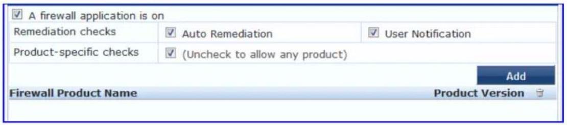
When enabled, the Firewall detail page appears.
Figure 270: Firewall Page (Detail 2)
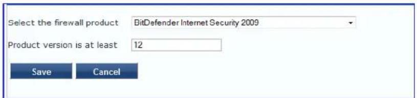
When you save your Firewall configuration, it appears in the Firewall page list.
Figure 271: Firewall Page (Overview After)
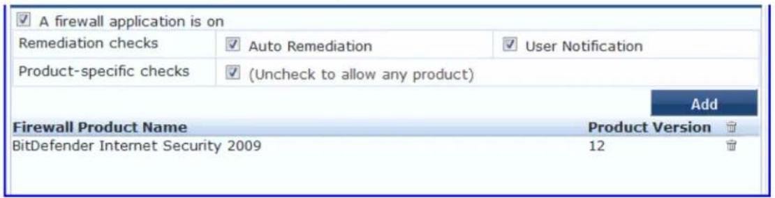
The following table describes the Firewall parameters:
Table 154: Firewall Page Parameters
| Interface | Parameter Description | |
| Firewall Page | A Firewall Application is OnAuto RemediationUser NotificationUncheck to allow any product | Check theFirewall Application is Oncheck box to enable testing of health data for configured firewall application(s).Check theAuto Remediationcheck box to enable auto remediation of firewall status.Check theUser Notificatiencheck box to enable user notification of policy violation of firewall status.Uncheck theUncheck to allow any productcheck box to check whether any firewall application (any vendor) is running on the end host. |
| Firewall Page (Detail 1) | AddTrashcan icon | To configure firewall application attributes for testing against health data, click Add.To remove configured firewall application attributes from the list, click thetrashcan iconin that row. |
| Firewall Page (Detail 2) | Product/Version | Configure the specific settings for which to test against health data. All of these checks may not be available for some products. Where checks are not available, they are shown in disabled state on the UI.Select the firewall product - Select a vendor from the listProduct version is at least - Enter the version of the product. |
Peer To Peer
The Peer To Peer page provides a set of widgets for specifying specific peer to peer applications or networks to be explicitly stopped. When you select a peer to peer network, all applications that make use of that are stopped.
The following figure displays the Peer To Peer health class configuration page:
Figure 272: Peer to Peer Page
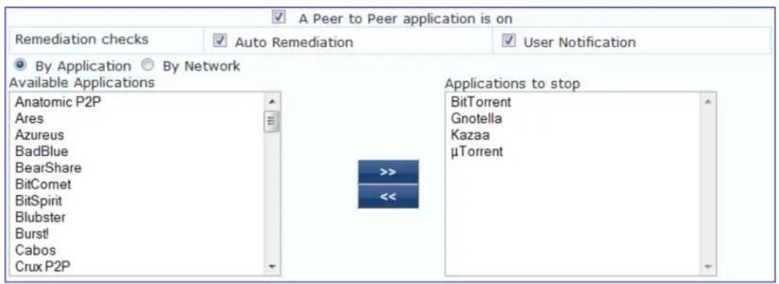
The following table describes the Peer to Peer parameters:
Table 155: Peer to Peer Page
| Parameter Description | |
| Auto Remediation | Enable to allow auto remediation for service checks (Automatically stop peer to peer applications based on the entries inApplications to stopconfiguration). |
| User Notification | Enable to allow user notifications for peer to peer application/network check policy violations. |
| By Application / By Network | Select the appropriate radio button to select individual peer to peer applications or a group of applications that use specific p2p networks. |
| Available Applications | This scrolling list contains a list of applications or networks that you can select and move to theApplications to stoppanel.Click the >> or << to add or remove, respectively, the applications or networks from theApplications to stopbox. |
Patch Management
The Patch Management page provides a way to specify that a patch management application must be on.
You can also specify information about the patch management application, configure the Product Evaluati Rule, and configure patch management application checks.
To configure patch-management application(s):
- Navigate to Configuration > Posture > Posture Policies, then click Add.
The Add Posture Policies dialog opens.
-
Select the Posture Plugins tab.
-
Click the check box for ClearPass Windows Universal System Health Validator.
-
Click Configure.
The ClearPass Windows Universal System Health Validator page opens.
-
Select the desired version of Windows.
-
From the selected version of Windows list, select Patch Management.
-
To enable checks for the selected version, click the Enable checks for Windows Server check box.
-
Click the A patch management application is on check box.
The Patch Management configuration dialog opens.
Figure 273: ClearPass Windows Universal System Health Validator: Patch Management
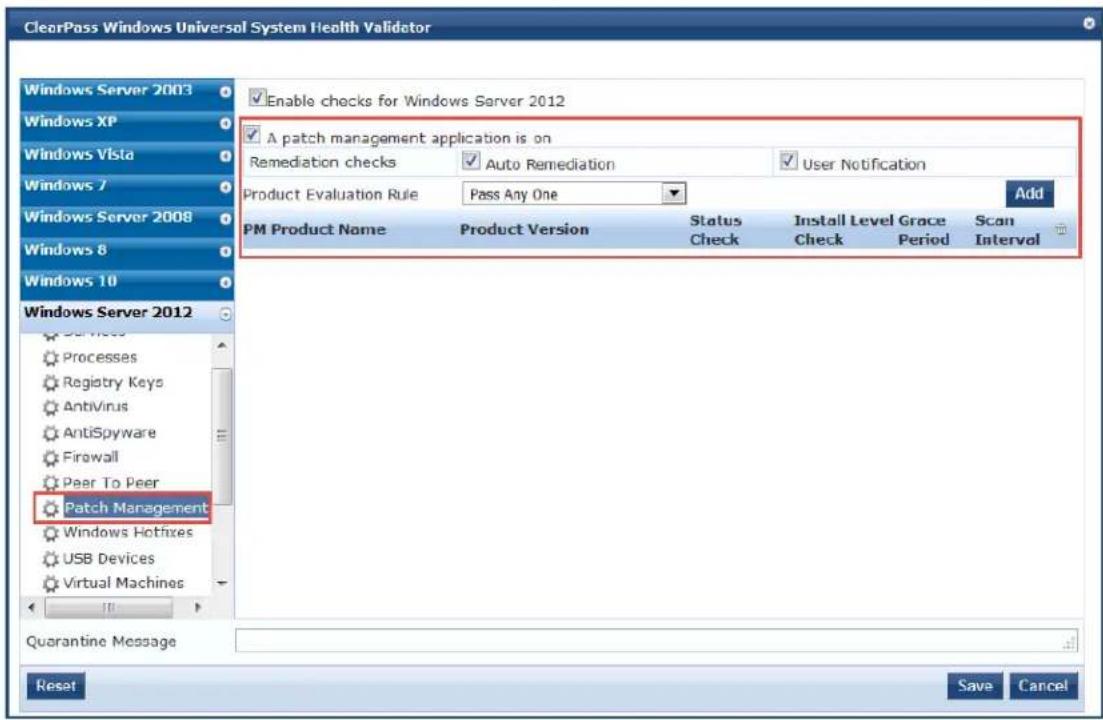
- Specify the Patch Management parameters as described in the following table.
Table 156: Patch Management Parameters
| Parameter Action/Description | |
| A patch management application is on | To enable testing of health data for configured Antivirus application(s), check the patch management application is on check box.The Patch Management configuration dialog opens |
| Remediation Checks | |
| Auto Remediation To enable auto-remediation of patch management status, check the Auto Remediation check box. | |
| User Notification To enable user notification of policy violation of patch management status, check the User Notification check box. | |
| Product Evaluation Rule | |
| Product Evaluation Rule | Select the appropriate Product Evaluation Rule:Pass All: Select this product evaluation rule if you want the Patch Management health class to be deemed as healthy only if all the configured patch manage products are present.Pass All is the equivalent of an AND condition.Pass Any One: Select this product evaluation rule if you want the Patch Management health class to be deemed as healthy if any one of the configured patch management products are present.Pass Any One is the equivalent of an OR condition.Pass Any One is the default. |
- To configure patch management application checks, click Add.
The Patch Management Health Checks configuration page opens:
Figure 274: Configuration Page for the Patch Management Application
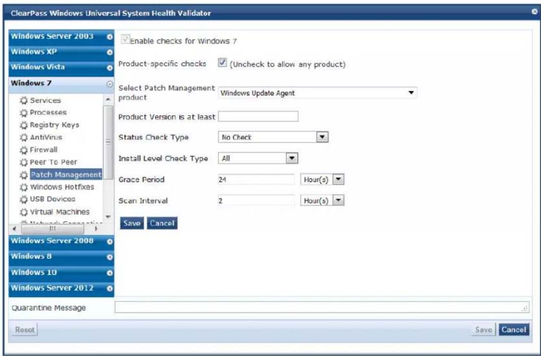
- Specify these parameters as described in the following table:
All checks might not be available for some products. Where checks are not available, they are shown in a disabled state.
Table 157: Patch Management Parameters
| Parameter Action/Description | |
| Product-specific checks To check | whether any patch management application (any vendor) is running on the end host, clear theUncheck to allow any productcheck box. |
| Select Patch Management Product | Select a patch management product vendor.This option is enabledonlyif theProduct-specific checkscheck box is checked. |
| Product version is at least Enter | the minimally recommended product version number.This option is enabledonlyif theProduct-specific checkscheck box is checked. |
| Status Check Type | Specify theStatus Check Typeto check whether the Patch Agent is enabled.The W-ClearPass Policy Manager server compares the Patch Agent Status sent by OnGuard Agent with the configured value. If the Patch Agent State value is different from configured value, the client is treated as unhealthyIfAuto-remediationis enabled, OnGuard Agent changes the Patch Agent Status on the client to the configured value. Select any of the following |

Table 157: Patch Management Parameters (Continued)
| Parameter Action/Description | |
| No Check: W-ClearPass Policy Manager server ignores the Patch Agent Status value. This means it will not check the status of the Agent application on the client.Enabled: Patch Agent is turned on and it automatically updates the client. Disabled: Patch Agent is disabled and it will not check for missing patches and update the client. Notify Before Download: Patch Agent is turned on and it notifies the user before downloading updates. Notify Before Install: Patch Agent is turned on and it notifies the user before installing updates.NOTE: The values specific to the selected patch management product are displayed in the Status Check Type field. For example, all five values are displayed for Microsoft Windows Automatic Update. For Microsoft System Center Configuration Manager (SCCM), only No Check, Disabled, and Notify Before Install are displayed. | |
| Install Level Check Type | This option is only enabled if the Product-specific checks check box is checked. For Microsoft SCCM, selecting All will return the full list of all missing patches.No Check: W-ClearPass Policy Manager server ignores the Patch Agent Status value. This means it will not check the status of the Agent application on the client.All: Checks for all missing patches and searches for all available patches.NOTE: If you select the Microsoft Windows Update Agent from the Select Patch Management product list and you select an option from the Install Level Check Type list, the results are as follows:All: Returns the full list of missing patches.No Check: Disables the Grace Period and Scan Interval fields. |
| Grace Period Configure the time | period for which OnGuard Agent should ignore missing patches.You can specify the grace period in hours, days, weeks, or months. For example, if the Grace Period is set to 3 days, clients will be treated as healthy for three days even if some patches are missing. After three days, OnGuard Agent will treat clients as unhealthy if the patches are still missing. You can enable Auto-remediation to install the missing patches and to treat them as healthy.If you selected No Check from the Install Level Check Type field, Grace Period is disabled. |
| Scan Interval | Specify the Scan Interval by specifying the number of hours, days, weeks, or months.If you selected No Check from the Install Level Check Type field, Scan Interval is disabled. |
When you save your patch management configuration, the configuration information is displayed on the Patch Management page:
Figure 275: Patch Management Configuration Summary
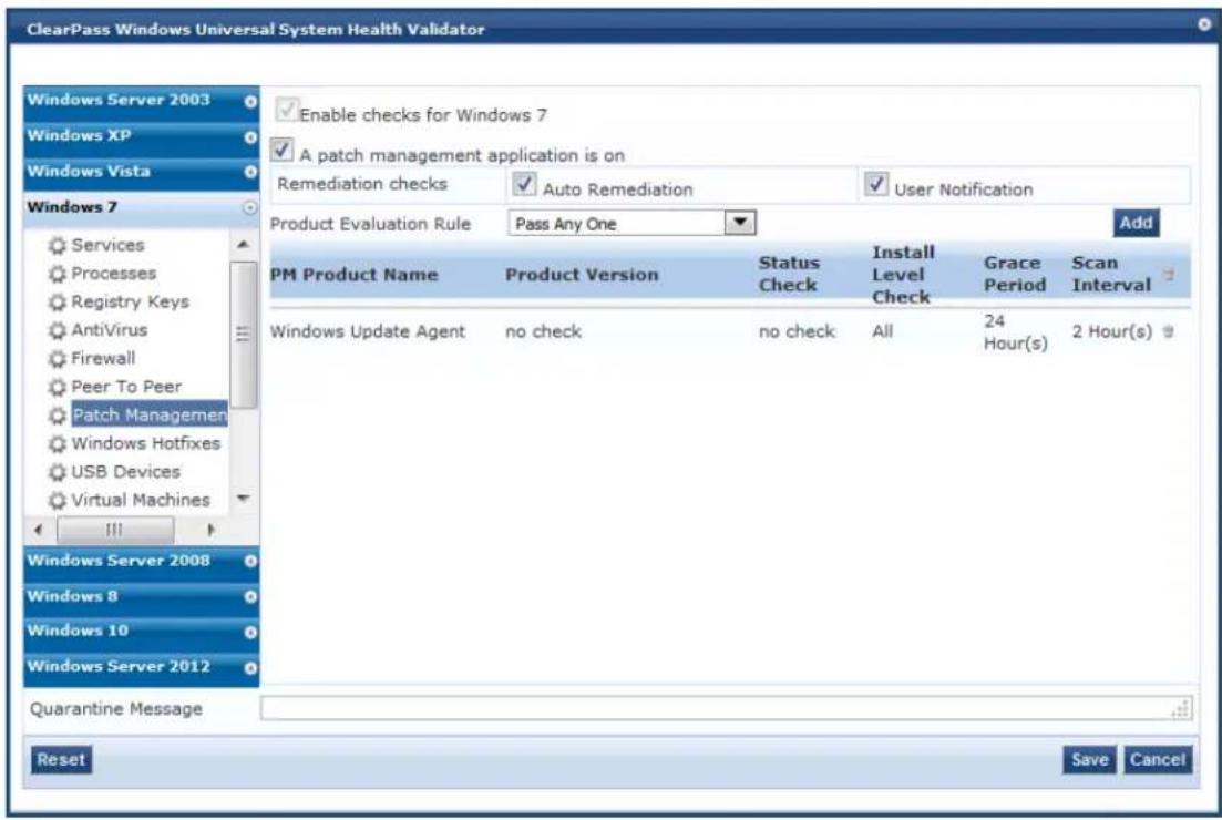
Windows Hotfixes
There are two Hotfixes evaluation rules that can be applied:
- The Windows Hotfixes Groups to be Present Evaluation Rule specifies how to evaluate the health among multiple Hotfixes groups (see Table 158 for details). For example, if the status of Group1 is [Hotfix1] AND [Hotfix 2], and the status of Group2 is [Hotfix3] OR [Hotfix4], the overall health status of the two groups is calculated as follows:
■ Pass All: ([Hotfix1] AND [Hotfix2]) AND ([Hotfix3] OR [Hotfix4])
■ Pass Any: ([Hotfix1] AND [Hotfix2]) OR ([Hotfix3] OR [Hotfix4])
- The Windows Hotfixes Group Evaluation Rule specifies how to evaluate the health for a specific Hotfixes group (see Table 159 for details).
To define Windows Hotfixes Groups, specify the evaluation rules for multiple groups or a single group, and add or remove specific Windows hotfixes on the endpoint:
-
Navigate to Configuration > Posture > Posture Policies, then click Add.
-
From the Add Posture Policies page, select the Posture Plugins tab.
-
Select the W-ClearPass Windows Universal System Health Validator, then click Configure.
-
Select the Windows operating system, then check the Enable checks for Windows_OS.
-
Select Windows Hotfixes.
The Windows Hotfixes health class configuration page opens:
Figure 276: Windows Hotfixes Page
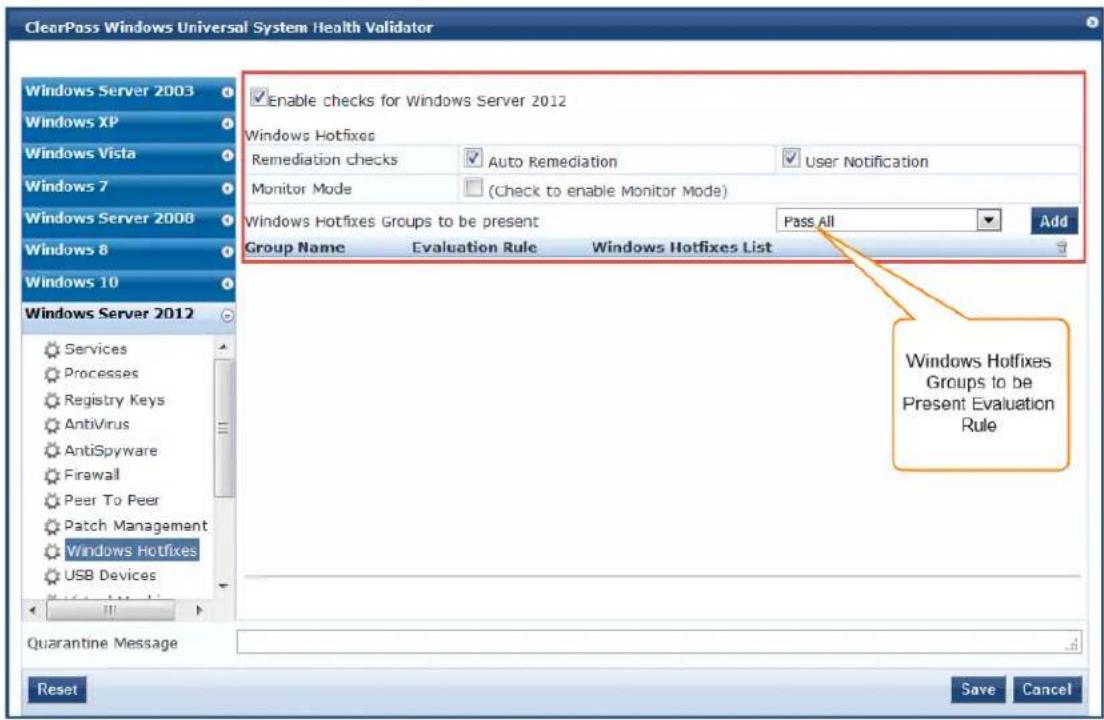
- Specify the Windows Hotfixes parameters as described in the following table:
Table 158: Windows Hotfixes Page Parameters
| Parameter Action/Description | |
| Auto Remediation Enable to allow auto-remediation for hotfix checks. Enabling this automatically triggers updates of the specified hotfixes.Auto-remediation for the Windows Hotfixes health class is enabled by default. | |
| User Notification Enable to allow user notifications to check for hotfix policy violations. | |
| Monitor Mode Click to enable | Monitor Mode. |
| Windows Hotfixes Groups to be Present Evaluation Rule | This evaluation rule specifies whether all groups should be healthy or any one group should be healthy.For example, if there are two Hotfixes Groups:Pass All: Select this evaluation rule to calculate the two group's health status as Group1 AND Group2.Pass Any One: Select this evaluation rule to calculate the two group's health status as Group1 OR Group2. |
Configuring Windows Hotfixes Groups to Be Present
To configure the Windows Hotfixes Groups to be present:
- From the Windows Hotfixes health class configuration page (see Figure 276), click Add.
The following Hotfixes dialog opens:
Figure 277: Defining the Hotfix Group
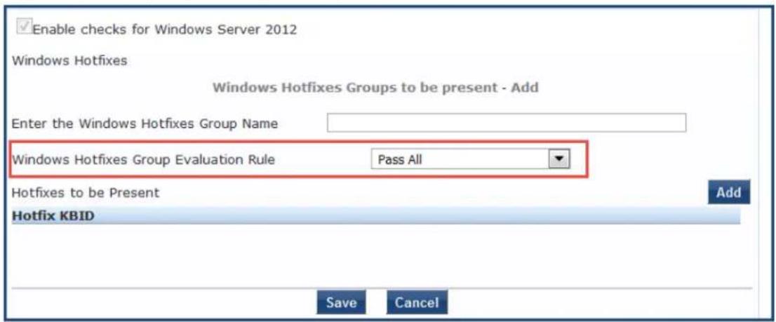
- Specify the Hotfixes Group parameters as described in the following table:
Table 159: Specifying Hotfixes Group to Be Present Parameters
| Parameter Action/Description | |
| Enter the Windows Hotfixes Group Name | Enter the name of the Hotfixes Group. |
| Windows Hotfixes Group Evaluation Rule | This evaluation rule specifies how to evaluate the health of a specific Hotfixes G Select the appropriate Hotfix Group Evaluation Rule:Pass All: Select this evaluation rule if you want all hotfixes groups to be present.Pass All is the equivalent of an AND condition.Pass Any One: Select this evaluation rule if you want any one of the hotfixes groups to be present.Pass Any One is the equivalent of an OR condition. |
| Hotfixes to be Present To | add hotfixes to the Hotfixes Group, click Add.The dialog shown in Figure 278 opens. |
Figure 278: Specifying the Hotfixes to Be Present
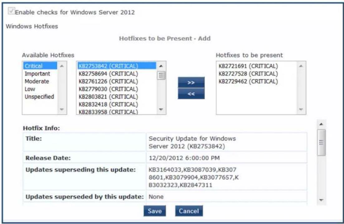
- From the first list, specify the criticality of the hotfixes:
• Critical
- Important
- Moderate
Low
- Unspecified
As shown in Figure 278, the list of hotfixes for the selected criticality are displayed.
- Select one or more of the desired hotfixes from the Available Hotfixes list.
As shown in Figure 278, when you select a Hotfix from the list of available hotfixes, information about that hotfix is displayed.
- To move hotfixes to the Hotfixes to be present box, select the desired hotfixes, then click >>.
The selected hotfixes are moved to the Hotfixes to be present box.
Figure 279: Windows Hotfixes Added
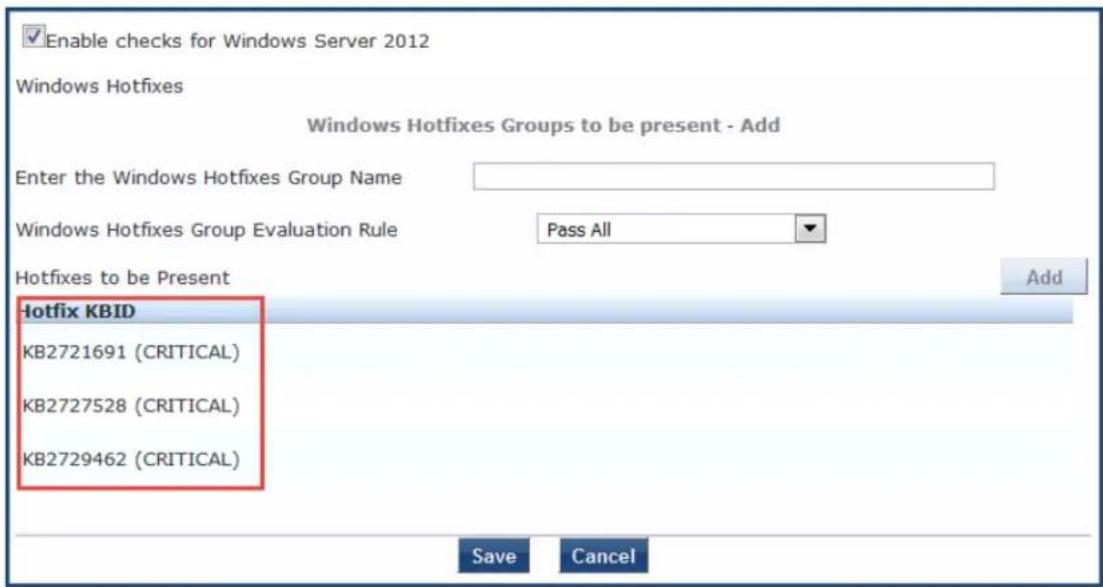
- To remove a hotfix from the Hotfixes to be present list, select the hotfix to be removed. The Edit Hotfixes to be Present dialog opens.
Figure 280: Removing Hotfixes from the Hotfixes to Be Present List
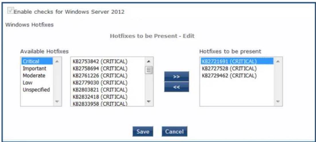
- From the Hotfixes to be present list, select the hotfix(es) you wish to remove and click <<. The selected hotfix is removed from the Hotfixes to be present list.
- When finished, click Save. You return to the Windows Hotfixes dialog, where the Hotfixes to be Present > Hotfix KBID (Knowledge Base Article ID) list displays the updated list.
- Click Save. The Windows Hotfixes page displays a summary of the Hotfixes Group configuration:
Figure 281: Summary of Hotfixes Groups Configuration
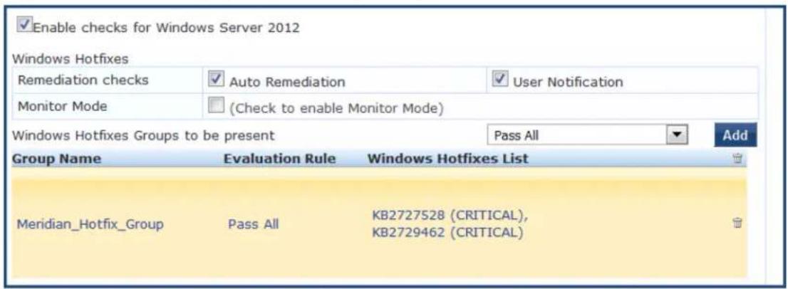
USB Devices
The USB Devices page provides configuration to control USB mass storage devices attached to an endpoint.
Figure 282: USB Devices
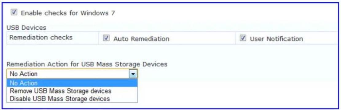
The following table describes the USB Devices parameters:
Table 160: USB Devices
| Parameter Description | |
| Auto Remediation Enable to allow auto remediation for USB mass storage devices attached to the endpoint (Automatically stop or eject the drive). | |
| User Notification Enable to allow user notifications for USB devices policy violations. | |
| Remediation Action for USB Mass Storage Devices | No Action - Take no action; do not eject or disable the attached devicesRemove USB Mass Storage Devices - Eject the attached devices.Remove USB Mass Storage Devices - Stop the attached devices. |
Virtual Machines
The Virtual Machines page provides configuration to Virtual Machines utilized by your network.
Figure 283: Virtual Machines
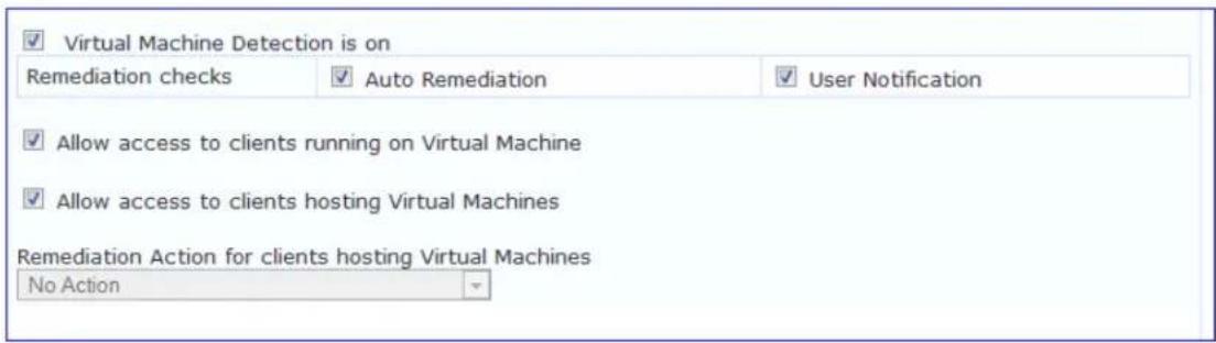
The following table describes the Virtual Machines parameters:
Table 161: Virtual Machines
| Parameter Description | |
| Auto Remediation Enable to allow auto | remediation for virtual machines connected to the endpoint. |
| User Notification Enable to allow user notifications for virtual machine policy violations. | |
| Allow access to clients running on Virtual Machine | Enable to allow clients that running a VM to be accessed and validated. |
| Allow access to clients hosting Virtual Machine | Enable to allow clients that hosting a VM to be accessed and validated. |
| Remediation Action for clients hosting Virtual Machines | No Action - Take no action; do not stop or pause virtual macStop all Virtual Machines running on Host - Stop the VM client that are running on Host.Pause all Virtual Machines running on Host - Pause the VM client that are running on Host. |
Network Connections
The Network Connections page provides configuration to control network connections based on connection type.
To configure Network Connections:
- From the W-ClearPass Windows Universal System Health Validator page, enable checks for the selected version of Windows.
- Select Network Connections.
- Enable the Network Connection Check is on check box.
The Network Connections configuration page appears.
Figure 284: Network Connections Configuration Page
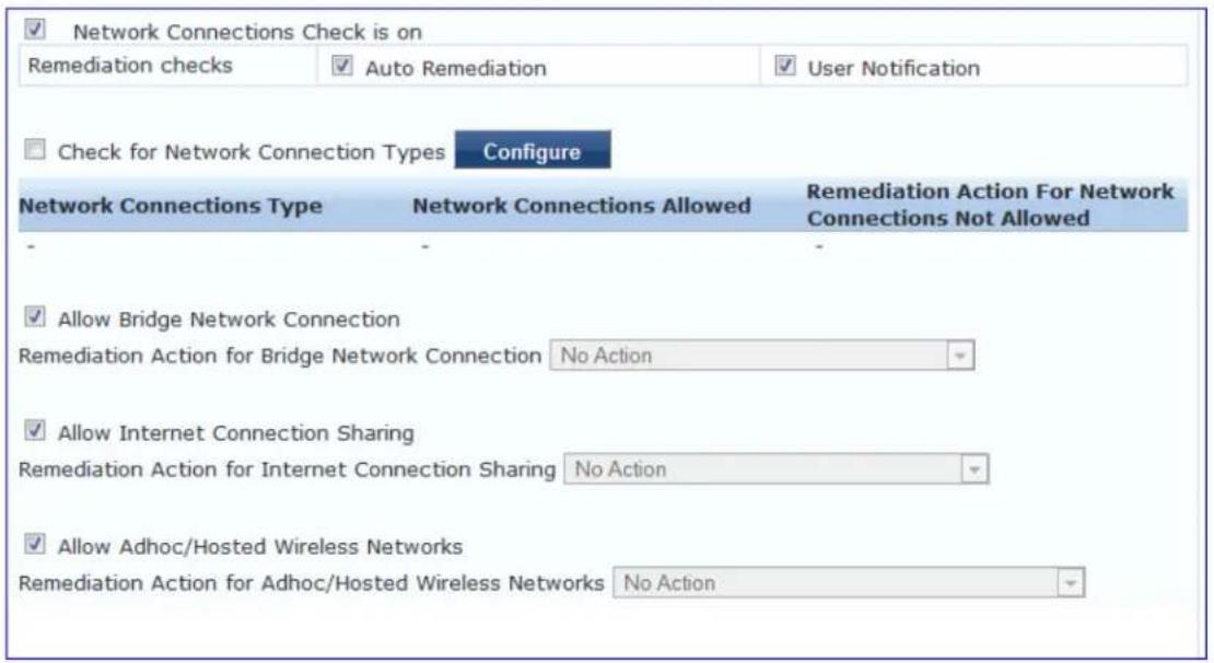
- Select the Check for Network Connection Types check box.
- To specify the type of connection that you want to include, click Configure.
The Network Connection Types configuration page appears.
Figure 285: Network Connection Types Configuration Page
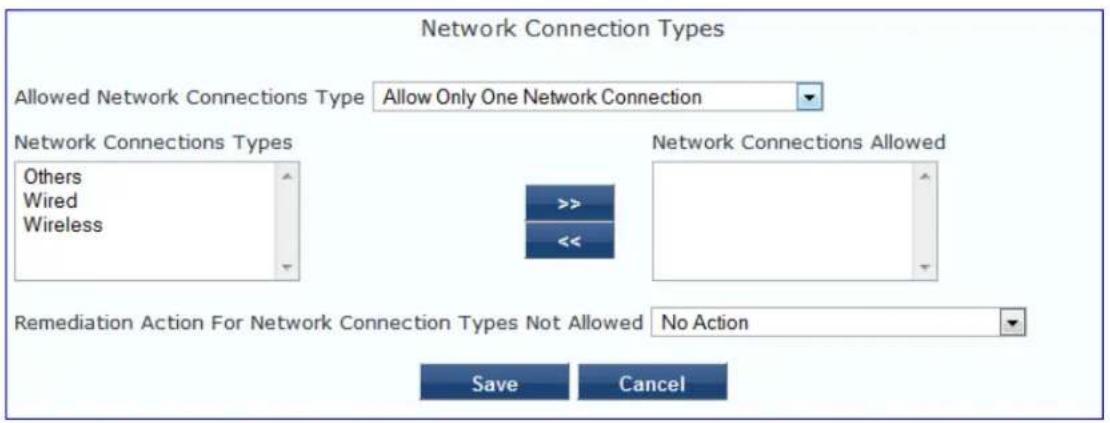
The following table describes the Network Connection Types configuration parameters:
Table 162: Network Connection Type Configuration Parameters
| Parameter Action/Description | |
| Allow Network Connections Type | 1. Select one of the following options:■ Allow Only One Network Connection■ Allow One Network Connection with VPN■ Allow Multiple Network Connections |
| Network Connection Types | 2. To add or remove Others, Wired, and Wireless network connection types, click >> or <<. |
| Remediation Action for Network Connection Types Not Allowed | 3. Specify one of the following■ No Action: Take no action. Do not eject or disable the attached dev■ Disable Network Connections■ Disconnect Network Connections |
| 4. Click Save. |
This returns you to the Network Connections configuration page. The following table describes the remaining fields on this page.:
Table 163: Network Connections Configuration Parameters
| Parameter Action/Description | |
| Auto Remediation 1. Enable to allow auto-remediation for network connections. | |
| User Notification | 2. Enable to allow user notifications in the event of network connection policy violations. |
| Remediation Action for Bridge Network Connection | 3. If Allow Bridge Network Connection is disabled, then specify whether to take no action when a bridge network connection exists or to disable all bridge network connections. |
| Remediation Action for Internet Connection Sharing | 4. If Allow Internet Connection Sharing is disabled, then specify whether to take no action when Internet connection sharing exists or to disable Internet con sharing. |
| Remediation Action for Adhoc/Hosted Wireless Networks | 5. If Allow Adhoc/Hosted Wireless Networks is disabled, then specify whether to take no action when an adhoc wireless networks exist or to disable all adhoc/hosted wireless networks. |
Disk Encryption
Disk encryption is a technology which protects information by converting it into unreadable code that can be deciphered easily by unauthorized people. Disk encryption uses disk encryption software or hardware encrypt every bit of data that goes on a disk or disk volume. Disk encryption prevents unauthorized acc data storage.
The following figure displays the Disk Encryption health class configuration page:
Figure 286: Disk Encryption Configuration Page
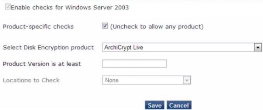
The following table describes the Disk Encryption parameters:
Table 164: Disk Encryption Parameters
| Parameter Description | |
| User Notification | Enable to allow user notifications for virtual machine policy violations. |
| Product-specific checks | Clear to allow disk encryption on any product. The Select Disk Encryption proof and Product Version is at least fields are disabled after you clear the check book |
| Select Disk Encryption product | Select a specific disk encryption product. |
| Product Version is at least | Search for the production version of the selected product. |
| Locations to Check | Select location to check. The options are None, System Root Drive, All Drives, Specific Locations. |
Installed Applications
The Installed Applications category groups classes that represent software-related objects. Access to these objects is supported by the Windows Installer. Examples of objects in this category are installed products specifications, and registration actions.
In the Installed Applications Configuration page (see Figure 287), you can turn on the installed applications check and specify information about which installed applications you want to monitor.
Figure 287: Installed Applications for Windows Configuration Page
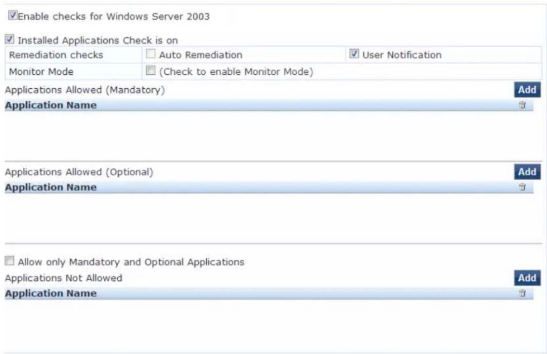
The following table describes the Installed Applications Configuration page parameters:
Table 165: Installed Applications for Windows Configuration Page Parameters
| Parameter Action/Description | |
| Remediation checksAuto-Remediationfor the | Installed Applicationshealth class is not supported. |
| User Notification 1. Enable sending a remediation message with a list of applications to install or uninstall to the user. | |
| Monitor Mode 2. EnableMonitor Modeto treat all the installed applications as always healthy. | |
| Applications Allowed (Mandatory) 3. Specify installed applications to be monitored on a mandatory basis. NOTE: Enter the application name as they are shown in Add/Remove Programs. | |
| Applications Allowed (Optional) 4. Specify installed applications to be monitored on an optional basis. NOTE: Enter the application name as they are shown in Add/Remove Programs. | |
| Allow only Mandatory and Optional Applications 5. Specify that only the mandatory and optional applications are monitored. NOTE: All applications that are not either mandatory or optional must be removed or uninstalled. | |
Enabling Regular Expressions for a Windows Application
To enable regular expressions for an application:
- From the ClearPass Windows Universal System Health Validator > Configure page (see Windows Universal System Health Validator on page 1), then select the desired version of Windows.
- Select Installed Applications.
- Click (enable) the Installed Applications Check is on check box.
The Installed Applications dialog appears (see Figure 287).
- From the desired Applications Allowed category, click Add.
The Add Mandatory Applications dialog for the selected Applications Allowed category appears.
Figure 288: Enabling Regular Expression
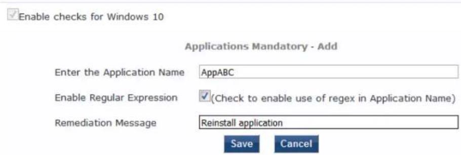
- Configure the Add Mandatory Applications parameters as described in Table 166.
Table 166: Mandatory Applications Parameters
| Parameter Action/Description | |
| Enter the Application Name | 1. Enter the name of the application. |
| Enable Regular Expression | 2. Check (enable) this check box to enable the use of regular expressions in the Application Name.When this field is enabled, W-ClearPass treats the Application Name as regular expression when comparing application names. |
| Remediation Message | 3. Optionally, enter the remediation message that will be displayed to the user in the of an error.NOTE: Remedition messages can include reasons for remediation, links to helpful URLs helpdesk contact information. |
| 4. Click Save. | |
You return to the Installed Applications dialog, where Regular Expression
Enabled is set to true for the specified application (see Figure 289).
Figure 289: Regular Expression Enabled
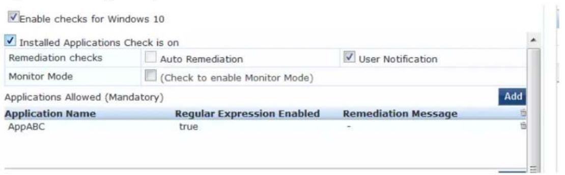
File Check
Use the File Check page to verify the group of files to present or absent. In the File Check page, you can turn on the file check and specify information about which the files you want to check.
The following figure displays the File Check Health Class configuration page:
Figure 290: Windows File Check Health Class Configuration
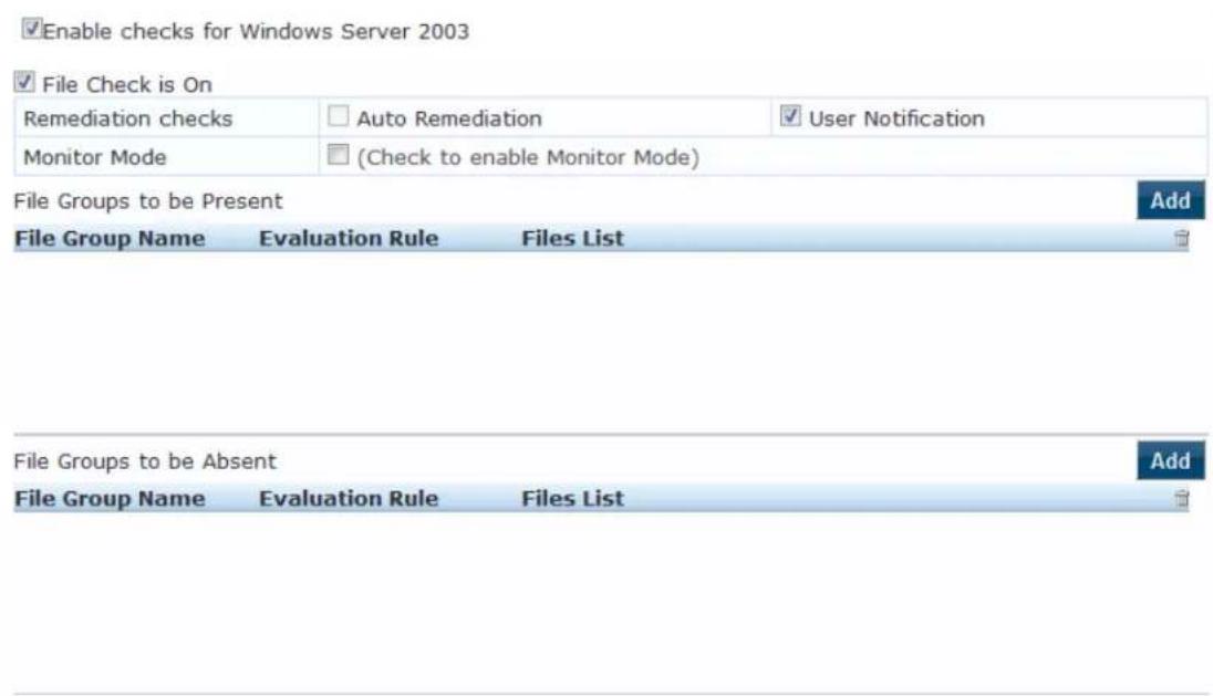
The following table describes the File Check Configuration parameters:
Table 167: File Check Configuration Parameters
| Parameter Action/Description | |
| Remediation checks Auto-remediation for the File Check health class is not supported. | |
| User Notification 1. When enabled, a remediation message that includes the groups of files to be present or absent is displayed to the end user. | |
| Monitor Mode | 2. To treat all the file check health classes as always healthy, enable Monitor Mode. |
| File Groups to be Present | 3. To add the files to be present in the File Check health class, click Add. |
| File Groups to be Absent | 4. To add the files to be absent in the File Check health class, click Add. |
Defining the File Group to Be Present
1. To open the File Group to be Present > Add page, click Add:
You can configure the name of the file group and specify the evaluation rule for the file group. The following figure displays the File Group to Be Present > Add dialog:
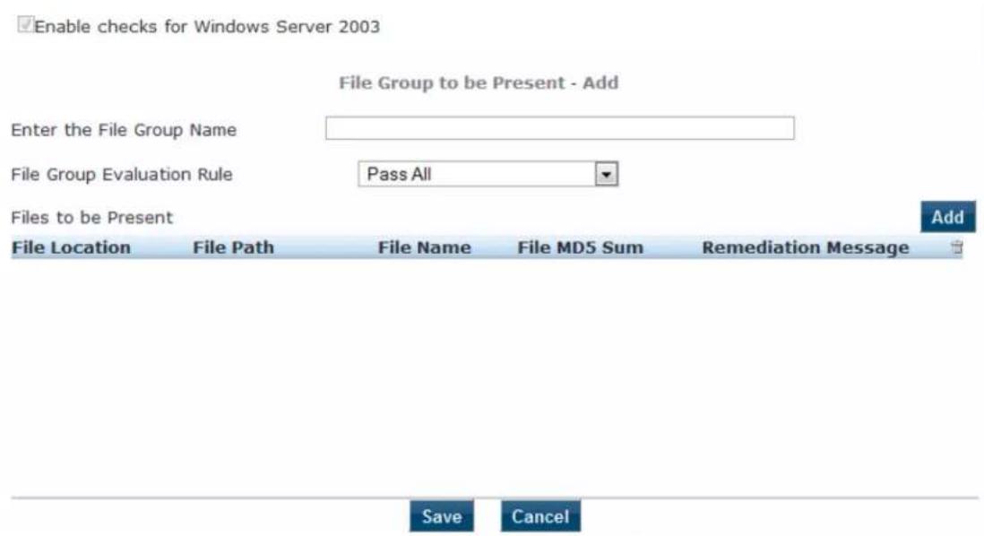
The following table describes the File Group to be Present > Add parameters:
Table 168: File Group to be Present - Add Parameters
| Parameter Action/Description | |
| Enter the File Group Name | 1. Enter the name of the file group. |
| File Group Evaluation Rule | 2. Select the appropriate File Group Evaluation Rule:Pass All: Select this evaluation rule if you want the File Check health class to be deemed as 'healthy' only if all the configured file groups are present.Pass Any One: Select this evaluation rule if you want the File Check health class to be deemed as 'healthy' even if any one of the configured file groups are |
- To configure the name of the file group and the evaluation rule for the file group, from File Groups to be Present, click Add.
The following figure displays the File to Be Present > Add page:
Figure 291: File to be Present > Add Dialog
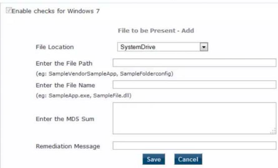
The following table describes the File to be Present > Add parameters:
Table 169: File to be Present > Add Parameters
| Parameter Action/Description | |
| File Location 1. Select any location of the file from the drop-down list:SystemDriveSystemrootProgramFilesProgramFiles (x86)HOMEDRIVEHOMEPATHNone | |
| Enter the File Path 2. Enter the file path as described in the examples from the user interface. | |
| Enter the File Name 3. Enter the name of the file. | |
| Enter the MD5 Sum Optionally, specify one or more (comma separated) MD5 checksums of the process executable file. | |
| Remediation Message | 4. Specify the custom remediation message to be displayed to end users if File check fails. |
5. When finished, click Save.
The parameters configured in the File to be Present > Add dialog are reflected in the File Groups to be Present page as illustrated in the following figure:
Figure 292: File Group to be Present Parameters Displayed
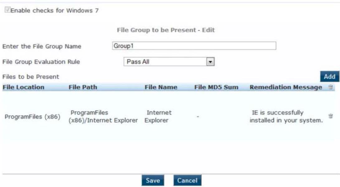
Windows System Health Validator: OnGuard Agent
This Windows System Health Validator checks for current Windows Service Packs. The OnGuard Agent als supports legacy Windows operating systems such as Windows Server 2003 and Windows Server 2012.
Use the check boxes to enable support of specific operating systems and to restrict access based on the Pack level.
To configure the Windows System Health Validator:
-
Navigate to Configuration > Posture > Posture Policies.
-
Click Add.
The Add Posture Policies dialog opens.
- Specify the following:
a. Policy Name: Enter the name of the posture policy.
b. Posture Agent: Onguard Agent
c. Host Operating System: Windows
-
Click Next.
-
From the Posture Plugins tab, select Windows System Health Validator, then click the Configure button.
The Windows System Health Validator page appears:
Figure 293: OnGuard Agent: Windows System Health Validator
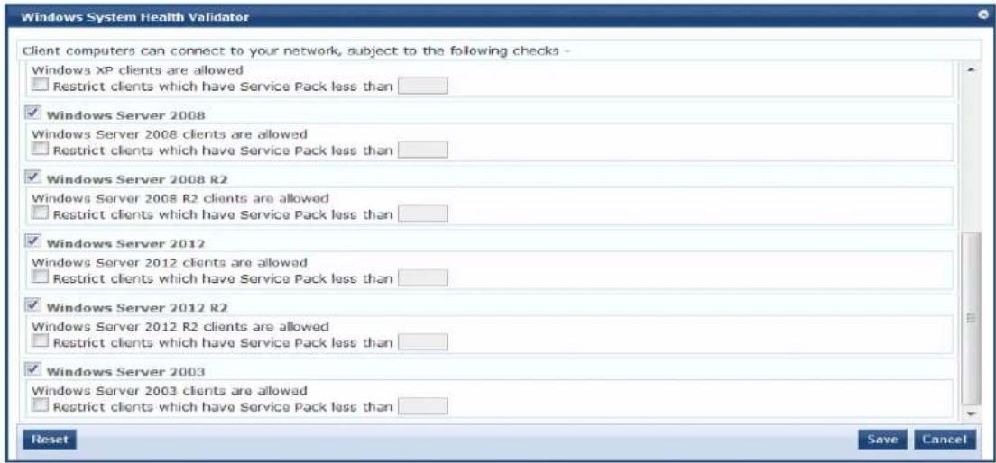
-
To enable support of specific operating systems, click the corresponding check box.
-
Enter the minimum Service Pack level required on the client computer to connect to your network.
-
Click Save.
Windows Security Health Validator: OnGuard Agent
The Windows Security Health Validator checks for the presence of specific types of security applications. can use the options to restrict access based on the absence of the selected security application types.
To configure the Windows Security Health Validator:
-
Navigate to Configuration > Posture > Posture Policies.
-
Click Add.
The Add Posture Policies dialog appears. Specify the following:
a. Policy Name: Enter the name of the posture policy.
b. Posture Agent: Onguard Agent
c. Host Operating System: Windows
-
Click Next.
-
From the Posture Plugins tab, select Windows Security Health Validator, then click the Configure button.
The following screen appears:
Figure 294: Onguard Agent: Windows Security Health Validator Page
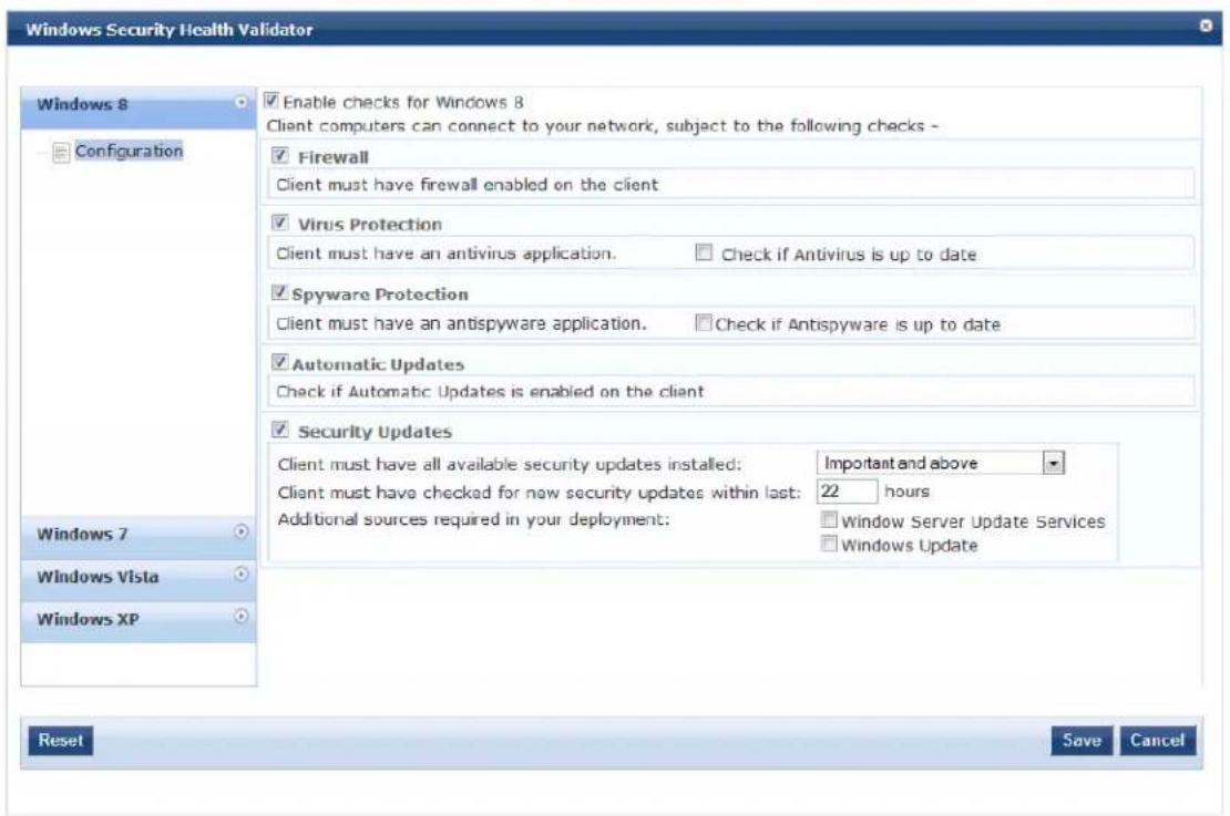
- To enable support of specific operating systems, click the corresponding check box.
- Enter the minimum Service Pack level required on the client computer to connect to your network.
- Click Save.
W-ClearPass Linux Universal System Health Validator Plugin
The W-ClearPass Linux Universal System Health Validator plugin appears on the Posture Plugins (Configuration > Posture > Posture Policies > Add) tab. Select the Linux host operating system and OnGuard Agent posture agent from the Policy tab in the Posture Policy page. Click Configure to configure antivirus settings and service types.
The OnGuard Dissolvable Agent version of the ClearPass Linux Universal System Health Validator plugin supports the following health classes:
• Antivirus on page 331
• Services on page 332
Antivirus
Use the Antivirus page to turn on an Antivirus application. Click An antivirus application is on to configure the Antivirus application information. The following figure displays the Antivirus health class configuration page:
Figure 295: Antivirus Page

The following table describes the Antivirus parameters:
Table 170: Antivirus Configuration Parameters
| Parameter Description | |
| Remediation checks Auto-remediation for the File Check health class is not supported. | |
| User Notification A remediation message having a list of files to present/absent will be displayed to end user. | |
| Antivirus Shows the name of the Antivirus configured. Click Add to configure the name of the Antivirus. | |
| Prd Version Shows the version of the Antivirus. | |
| Eng Version Shows the version of the engine. | |
| Dat Version Shows the version of the data file. | |
Click Add to configure the Antivirus product specific checks. The values configured in the Antivirus Product configuration pop-up will be displayed in the Antivirus page. The following figure is an example of the Antivirus Product configuration pop-up:
Figure 296: Antivirus Product configuration Pop-up
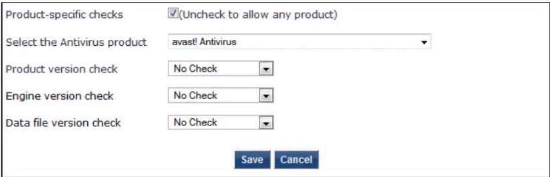
The following table describes the Antivirus Product configuration parameters:
Table 171: Antivirus Product configuration Parameters
| Parameter Description | |
| Product-specific checks Select this check box if you want to configure a specific antivirus product. If you want to allow any antivirus product, do not select this field. | |
| Select the Antivirus product | Select the Antivirus from the drop-down list. |
| Product version check Select to check the product version from the options: No Check, Is Latest, or In Last N Updates. | |
| Engine version check Select to check the engine version from the options: No Check, Is Latest, or In Last N Updates. | |
| Data file version check Select to check the data file version from the options: No Check, Is Latest, or In Last N Updates. | |
Services
The Services page provides a set of widgets for specifying services to run or stop. The following figure displays the Services page:
Figure 297: Services Page
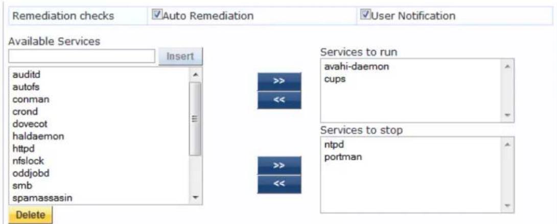
The following table describes the Services page parameters:
Table 172: Services Page
| Parameter | Description |
| Auto Remediation | Enable to allow auto remediation for service checks (Automatically stop or start services bas the entries inService to runandServices to stopconfiguration). |
| User Notification | Enable to allow user notifications for service check policy violations. |
| Available Services | This scrolling list contains a list of services that you can select and move to theServices to runorServices to stoppanels (using their associated widgets). This list varies depending on OS types.Click the >> or << to add or remove, respectively, the services from theService to runorServices to stopboxes. |
| Insert To add | a service to the list of available services, enter its name in the text box adjacent to this button, then clickInsert. |
| Delete To remove | a service from the list of available services, select it and clickDelete. |
W-ClearPass Macintosh OS X Universal System Health Validator: OnGuard Agent
To configure the W-ClearPass Universal System Health Validator for Macintosh OS X:
- Navigate to Configuration > Posture > Posture Policies, then click Add.
The Add Posture Policies dialog appears.
Figure 298: Adding a Universal System Health Validator for a Mac OS X Posture Policy
- Specify the following:
a. Policy Name/Description: Enter the name and a description of the posture policy.
b. Posture Agent: Select OnGuard Agent.
c. Host Operating System: Select Mac OS X.
- Click Next.
The Posture Plugins dialog appears.
Figure 299: Selecting the Mac OS X Universal System Health Validator Posture Plug-in
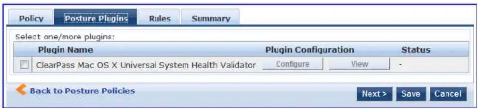
- In the Posture Plugins page, click the check box for ClearPass Mac OS X Universal System Health Validator.
- Click Configure.
The ClearPass Mac OS X Universal System Health Validator configuration page is displayed.
- To enable checks for Mac OS X, select the Enable checks for Mac OS X check box.
The following configuration page appears:
Figure 300: Configuration Page: Mac OS X Universal System Health Validator
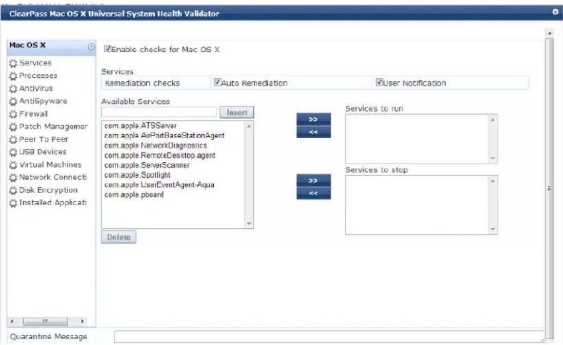
Enabling these check boxes display a corresponding set of configuration pages that are described in the following sections.
■ Services on page 335
■ Processes on page 335
■ Antivirus on page 336
■ AntiSpyware on page 337
■ Firewall on page 338
■ Patch Management on page 338
■ USB Devices on page 339
■ Virtual Machine on page 340
■ Network Connections on page 340
■ Disk Encryption on page 341
■ Installed Applications on page 342
■ File Check on page 345
Services
From the Services page, you can configure which services to run and which services to stop. See ClearPass Windows Universal System Health Validator > OnGuard Agent on page 289 for description of the fields on this page.
The following figure displays the Services health class configuration page:
Figure 301: Services Health Class Configuration Page
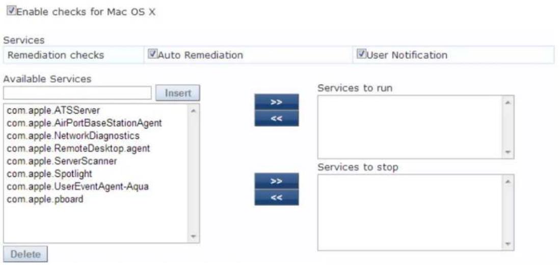
Processes
From the Processes page, you can view and add processes. Clicking Enable checks for Mac OS X provides a set of components to specify the processes that need to be explicitly present or absent on the system.
Figure 302: Processes Page
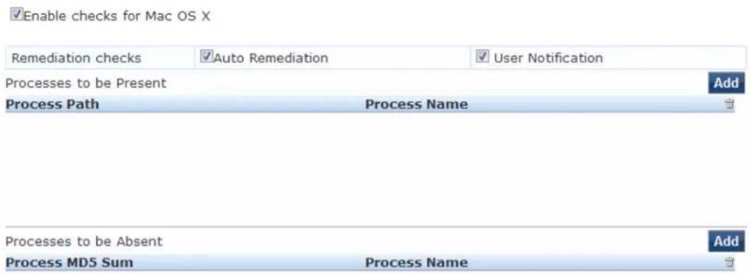
Click Add to open the page with options to configure the name, location, and display name of the processes. The following figure displays the Process to be Present - Add page:
Figure 303: Processes to be Present - Add Page
☑ Enable checks for Mac OS X
Process to be Present - Add
Process Location
Applications

Enter the Process name

Enter the Display name

Save
Cancel
Antivirus
In the Antivirus page, you can specify information about the antivirus application. Click on An antivirus-application is on to configure the anti-virus application information.
The following figure displays the Antivirus page:
Figure 304: Antivirus Page (Detail 1)

Click Add to specify product and version check information in the antivirus configuration page.
Figure 305: Antivirus Configuration Page (Detail 2)
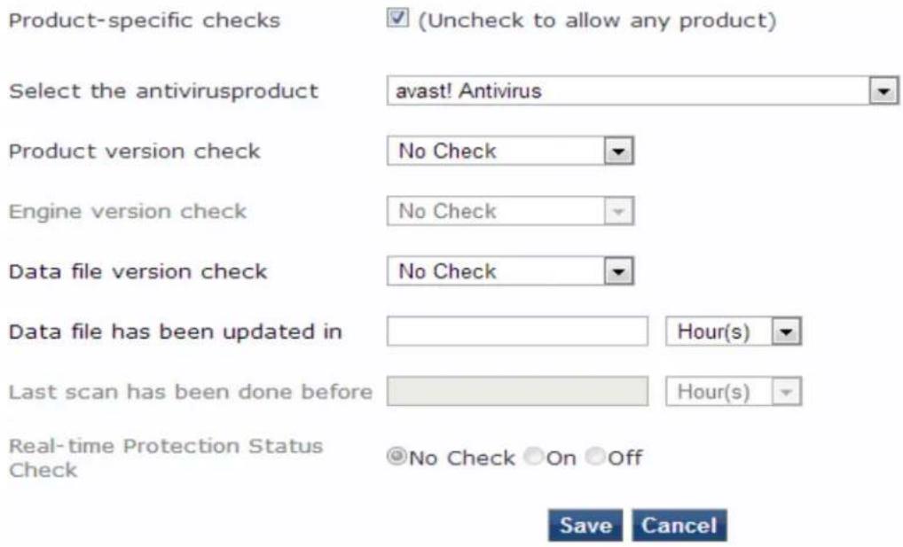
When you save your antivirus configuration, it appears in the Antivirus page list. See ClearPass Windows Universal System Health Validator > OnGuard Agent on page 289 for antivirus page and field descriptions.
AntiSpyware
In the AntiSpyware page, an administrator can specify information about the antispyware application. The following figures describe the examples of the AntiSpyware page and the AntiSpyware - Add page:
Figure 306: Anti-Spyware Page

In the Antispyware page, click An Antispyware Application is On to configure different configuration elements specific to the antispyware product that you select. When you save the antispyware configuration appears in the Antispyware page list.
Figure 307: Anti-Spyware Add Page
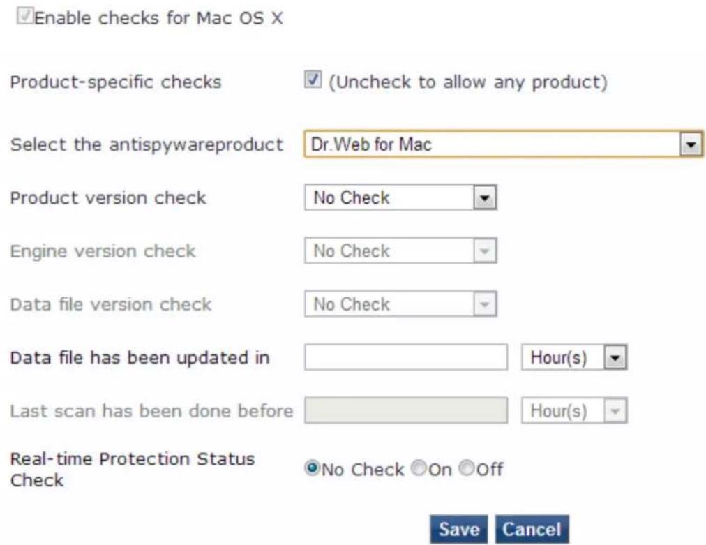
The configuration elements are the same for antivirus and antispyware products.

Firewall
From the Firewall page, click A Firewall Application is On to configure the firewall application information. The following figure displays the Firewall page:
Figure 308: Firewall Page
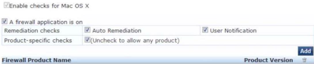
Click Add from the Firewall page to configure different configuration elements specific to the firewall product that you select. When you save the firewall configuration, it appears in the Firewall page list.
Figure 309: Firewall Add Page
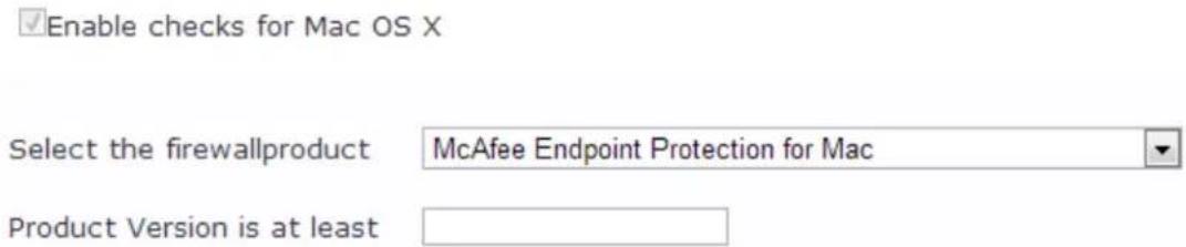
When enabled, the Firewall detail page appears. See ClearPass Windows Universal System Health Validator > OnGuard Agent on page 289 for firewall page and field descriptions.
Patch Management
From the Patch Management page, you can view and add the patch management product. Select A patch management application is on to configure auto remediation and user notification features.
The following figure displays the Patch Management page:
Figure 310: Patch Management Page

Click Add in the Patch Management page to view the configuration options for the specific patch management product. The following figure displays the Patch Management - Add page:
Figure 311: Patch Management - Add Page
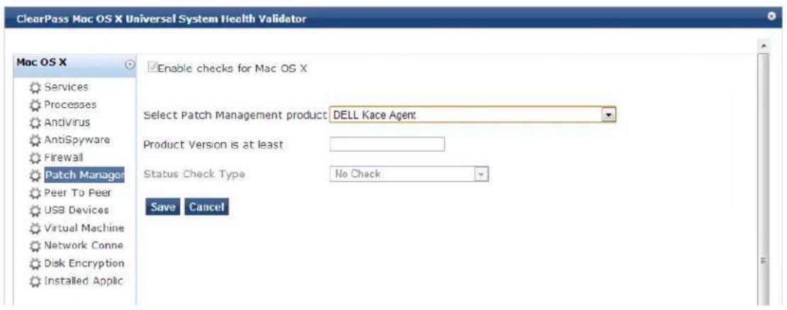
Peer To Peer
From the Peer To Peer page, you can view and add peer-to-peer applications. Clicking A Peer to Peer application is on provides configuration options to specify peer to peer applications or networks that need to be explicitly stopped. When you select a peer to peer network, all applications that make use of that ne are stopped.
The following figure displays the Peer To Peer page:
Figure 312: Peer To Peer Page
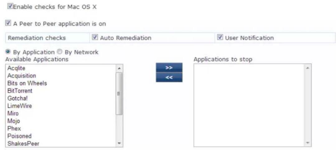
USB Devices
Use this page to configure the Auto Remediation and User Notification parameters. You can also configure the options to take remediation action for USB mass storage devices or to remove USB mass storage device from the Remediation Action for USB Mass Storage Devices drop-down.
The following figure displays the USB Devices page:
Figure 313: USB Devices Page

Virtual Machine
The Virtual Machines page provides configuration options to virtual machines utilized by the network. Select the Virtual Machine Detection is on option to enable the Auto Remediation and User Notification options.
The following figure displays the Virtual Machine page:
Figure 314: Virtual Machine Page
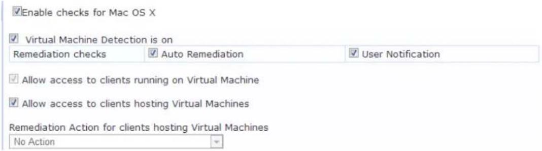
Network Connections
The Network Connections page provides configuration options to control network connections based on connection type. Enabling the Network Connection Check is on check box provides the options to specify the remediation checks or user notification.
The following figure displays the Network connections page:
Figure 315: Network Connections Page
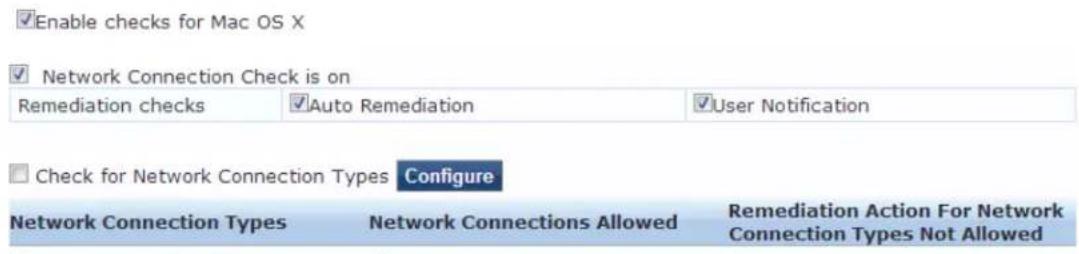
Select the Check for Network Connection Types check box from the Network Connections page, and then click Configure to specify type of network connection. You can select and allow the network connection types from the Network Connections Configuration page as described in the following figure:
Figure 316: Network Connections Configuration Page
√Enable checks for Mac OS X
Network Connection Types
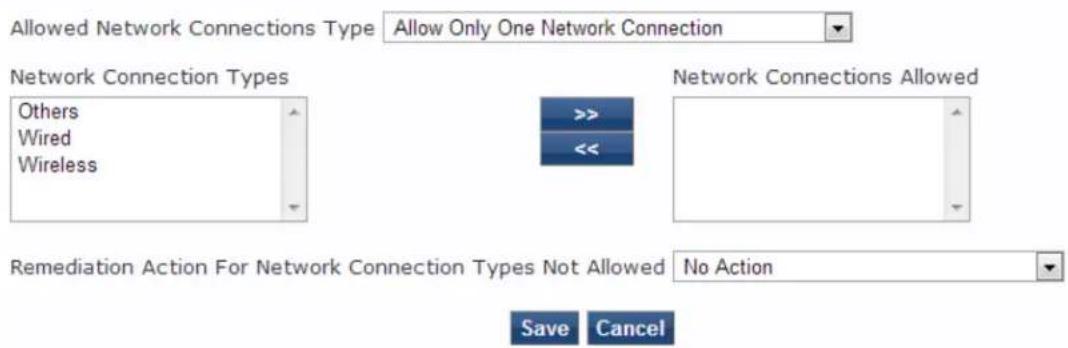
Disk Encryption
Disk encryption is a technology that protects information by converting it into unreadable code that can be deciphered easily by unauthorized people. Disk encryption uses disk encryption software or hardware to encrypt every bit of data that goes on a disk or disk volume. Disk encryption prevents unauthorized access to data storage.
The following figure displays the Disk Encryption page:
Figure 317: Disk Encryption Page

Click A disk encryption application is on from the Disk Encryption page to configure the remediation options. Click Add to configure the product specific encryption checks. You can select the Uncheck to allow any product check box from the Product-specific checks field to not to allow any encryption product to check disk encryption.
The following image is an example of the Disk Encryption - Add page:
Figure 318: Disk Encryption Add Page
√Enable checks for Mac OS X
Product-specific checks
(Uncheck to allow any product)
Select Disk Encryption product
CREDANT Shield

Product Version is at least

Locations to Check
None
Save
Cancel
Installed Applications
The Installed Applications category groups classes that represent software-related objects.
From the Installed Applications page, you can specify information about which installed applications you want to monitor.
Figure 319: Installed Applications Page for Macintosh OS X
√Enable checks for Mac OS X
√ Installed Applications Check is on
Remediation checks
Auto Remediation
User Notification
Monitor Mode
☑ (Check to enable Monitor Mode)
Applications Allowed (Mandatory)
Add
Application Name
图
Applications Allowed (Optional)
Add
Application Name
音
☐ Allow only Mandatory and Optional Applications
Add
Applications Not Allowed
雷
Application Name
The following table describes the Installed Applications for Mac OSX Configuration page parameters:
Table 173: Installed Applications for Mac OS X Configuration Page Parameters
| Parameter Action/Description | |
| Remediation checksAuto-Remediationfor the | Installed Applicationshealth class is not supported. |
| User Notification 1. Enable sending a remediation message with a list of applications to install or uninstall to the user. | |
| Monitor Mode 2. EnableMonitor Modeto treat all the installed applications as always healthy. | |
| Applications Allowed (Mandatory) 3. Specify installed applications to be monitored on a mandatory basis.NOTE:Enter the application names as they are shown in Add/Remove Programs. | |
| Applications Allowed (Optional) 4. Specify installed applications to be monitored on an optional basis.NOTE:Enter the application name as they are shown in Add/Remove Programs. | |
| Allow only Mandatory and Optional Applications | 5. Specify that only the mandatory and optional applications are monitored.NOTE:All applications that are not either mandatory or optional must be removed or uninstalled. |
Enabling Regular Expressions for a Mac OS X Application
To enable regular expressions for an application:
-
From the ClearPass Windows Universal System Health Validator > Configure page (see W-ClearPass Macintosh OS X Universal System Health Validator: OnGuard Agent on page 333), select Installed Applications.
-
Click (enable) the Installed Applications Check is on check box.
The Installed Applications dialog appears (see above).
- From the desired Applications Allowed category, click Add.
The Mandatory Applications dialog appears for the selected Applications Allowed category (see Figure 320).
Figure 320: Enabling Regular Expression
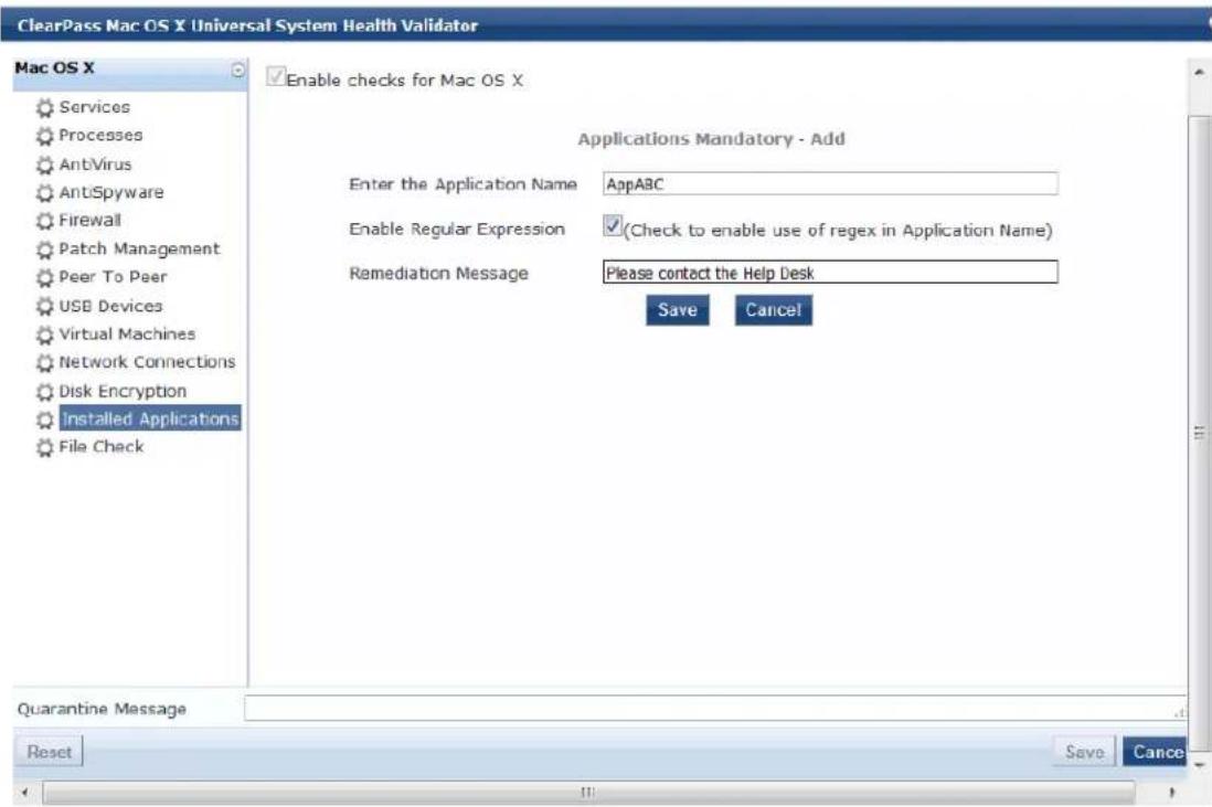
- Configure the Add Mandatory Applications parameters as described in Table 174.
Table 174: Add Mandatory Applications Parameters
| Parameter Action/Description | |
| Enter the Application Name | 1. Enter the name of the application. |
| Enable Regular Expression | 2. Check (enable) this check box to enable the use of regular expressions in the Application Name.When this field is enabled, W-ClearPass treats the Application Name as regular expression when comparing application names. |
| Remediation Message | 3. Optionally, enter the remediation message that will be displayed to the user in the of an error.NOTE: Remedition messages can include reasons for remediation, links to helpful URLs helpdesk contact information. |
| 4. Click Save. | |
You return to the Installed Applications dialog, where Regular Expression Enabled is set to true for the specified application (see Figure 321).
Figure 321: Regular Expression Enabled
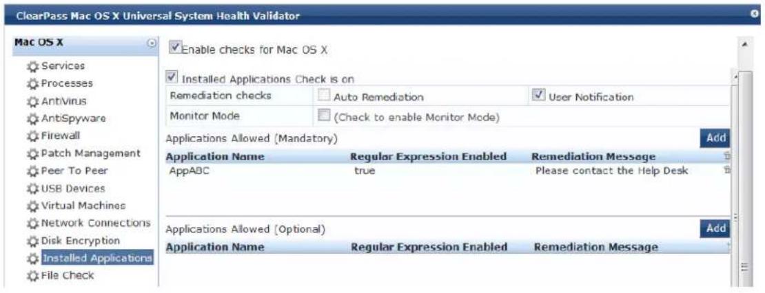
File Check
From the File Check page, you can turn on the file check feature and specify information about which the files you want to check.
Use the File Check page to verify the group of files to be present or absent.
The following figure is an example of the File Check health class configuration dialog:
Figure 322: Mac OS X File Check Health Class Configuration
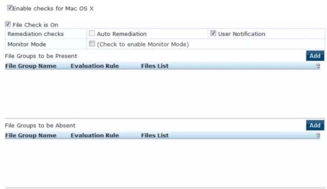
The following table describes the File Check Configuration parameters:
Table 175: File Check Configuration Parameters
| Parameter Action/Description | |
| Remediation checks | Auto-remediation for the File Check health class is not supported. |
| User Notification 1. When | enabled, a remediation message that includes the groups of files to be present or absent is displayed to the end user. |
| Monitor Mode | 2. To treat all the file check health classes as always healthy, enable Monitor Mode. |
| File Groups to be Present | 3. To add the files to be present in the File Check health class, click Add. |
| File Groups to be Absent | 4. To add the files to be absent in the File Check health class, click Add. |
1. To open the File Group to be Present > Add page, click Add:
You can configure the name of the file group and specify the evaluation rule for the file group. The following figure displays the File Group to Be Present > Add dialog:
Figure 323: MacOSX File Group to Be Present > Add Dialog
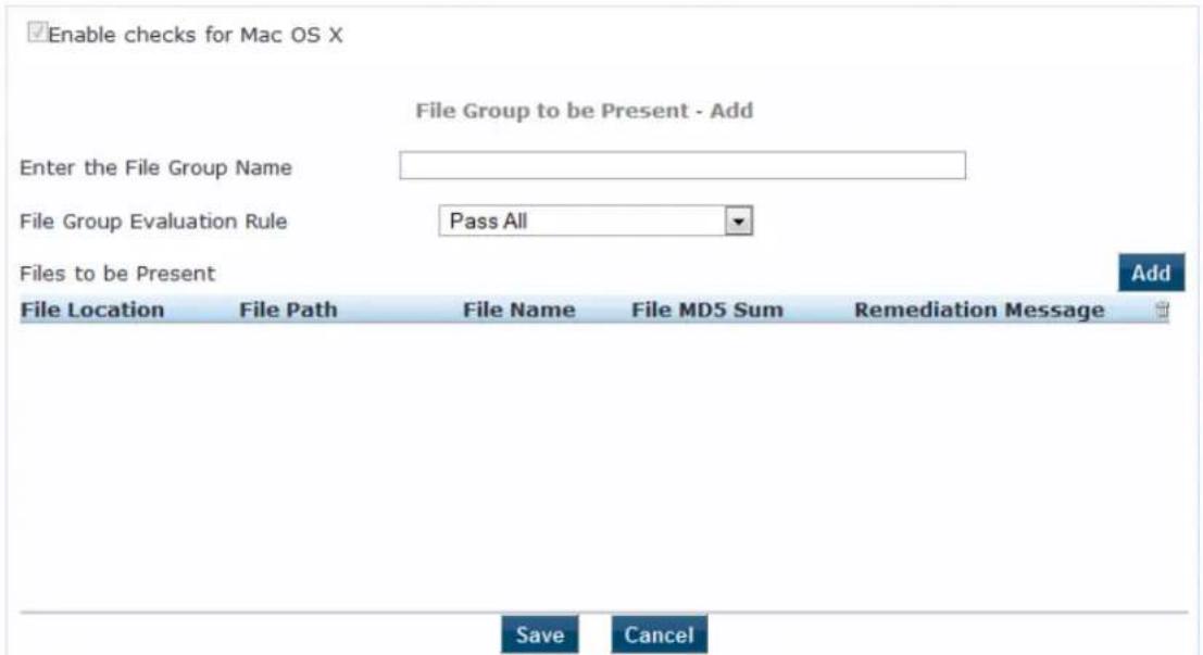
The following table describes the File Group to Be Present > Add parameters:
Table 176: File Group to Be Present > Add Parameters
| Parameter Action/Description | |
| Enter the File Group Name | 1. Enter the name of the file group. |
| File Group Evaluation Rule | 2. Select the appropriate File Group Evaluation Rule:Pass All: Select this evaluation rule if you want the File Check health class to be deemed as 'healthy' only if all the configured file groups are present.Pass Any One: Select this evaluation rule if you want the File Check health class to be deemed as 'healthy' even if any one of the configured file groups are |
- To configure the name of the file group and the evaluation rule for the file group, from File Groups to be Present, click Add.
The following figure displays the File to Be Present > Add page:
Figure 324: File to be Present > Add Dialog
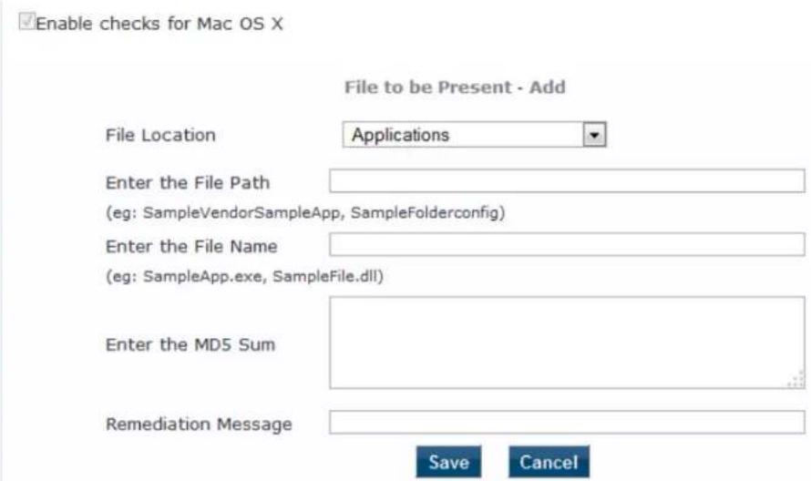
The following table describes the File to Be Present > Add parameters:
Table 177: File to Be Present > Add Parameters
| Parameter Action/Description | |
| File Location 1. Select any location of the file from the drop-down list:ApplicationsUserBinUserLocalBinUserSBinNone | |
| Enter the File Path 2. Enter the file path as described in the examples from the GUI. | |
| Enter the File Name 3. Enter the name of the file. | |
| Enter the MD5 Sum Optionally, you can specify one or more (comma separated) MD5 checksums of the process executable file. | |
| Remediation Message | 4. Specify the custom remediation message to be displayed to end users if File check fails. |
5. When finished, click Save.
The parameters configured in the File to Be Present > Add dialog are reflected in the File Groups to be Present dialog as illustrated in the following figure:
Figure 325: File Group to Be Present Parameters Displayed
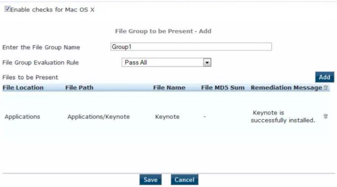
Configuring NAP Agent Plugins
If your posture policy is using a NAP agent, the Posture Plugins tab allows you to configure the following plug-in types:
• Windows System Health Validator: NAP Agent on page 349
• Windows Security Health Validator: NAP Agent on page 350
The following figure displays the NAP Agent - Posture Plugins tab:
Figure 326: NAP Agent - Posture Plugins Options
Windows System Health Validator: NAP Agent
The Windows System Health Validator NAP (Network Access Protection) Agent checks for the level of Wind Service Packs.
To configure the minimum service pack level required, perform the following steps:
- Navigate to Configuration > Posture > Posture Policies.
The Posture Policies page appears.
- Click Add.
The Add Posture Policies > Policy dialog opens.
Figure 327: Adding a Windows NAP Agent Posture Policy
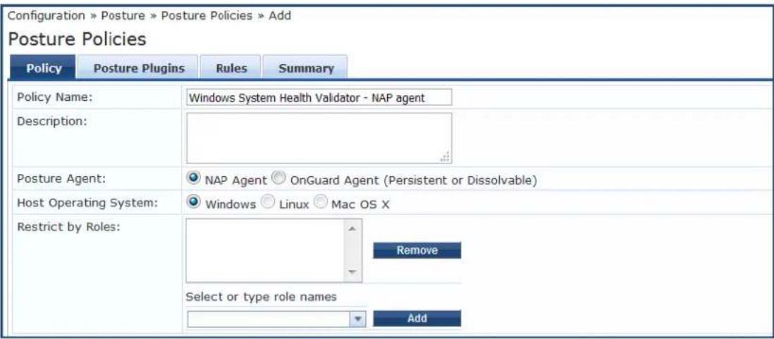
- Specify the following:
a. Policy Name/Description: Enter the name and description of the posture policy.
b. Posture Agent: Select NAP Agent.
c. Host Operating System: Select Windows.
- Click Next.
The Posture Policies > Posture Plugins page opens.
Figure 328: Posture Plugins for Windows Health Validators

- From the Posture Plugins tab, select Windows System Health Validator, then click the Configure button.
The Windows System Health Validator page appears:
Figure 329: Onguard NAP Agent: Windows System Health Validator
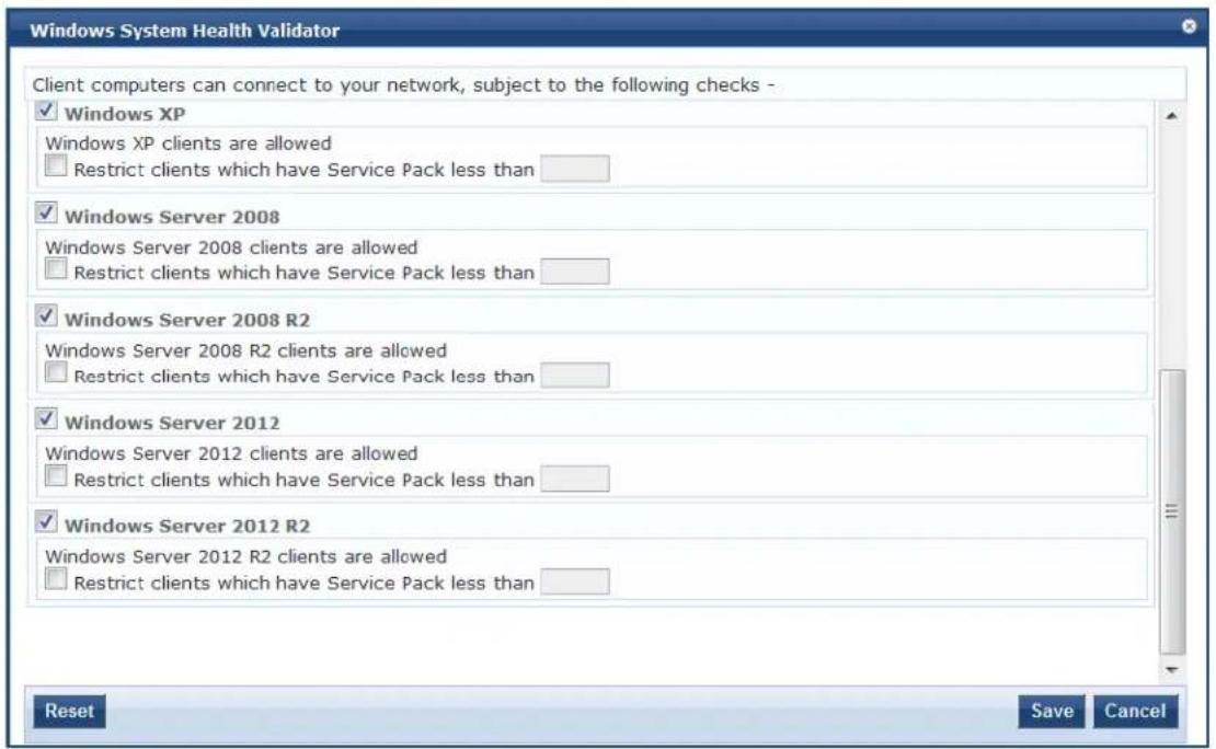
- To enable support of specific Windows operating systems, click the corresponding check boxes.
- Enable the Restrict clients... check box and specify the minimum Service Pack level required on the client computer to connect to your network.
- Click Save.
You return to the Posture Plugins page where the status of the plug-in is now set to Configured.
Windows Security Health Validator: NAP Agent
The Windows Security Health Validator: NAP (Network Access Protection) Agent checks for the presence of specific types of security applications. You can use the check boxes to restrict access based on the abse the selected security application types.
To configure the minimum service pack level required, perform the following steps:
- Navigate to Configuration > Posture > Posture Policies.
The Posture Policies page appears.
- Click Add.
The Add Posture Policies dialog appears.
Figure 330: Adding Windows Security Health Validator: NAP Agent Posture Policy
- Specify the following:
a. Policy Name: Enter the name of the posture policy.
b. Posture Agent: Select NAP Agent.
c. Host Operating System: Select Windows.
- Click Next.
The Posture Policies > Posture Plugins page appears.
Figure 331: Selecting Posture Plugins for Windows Security Health Validator: NAP Agent

- From the Posture Plugins page, select Windows Security Health Validator, then click Configure.
The Windows System Health Validator page appears:.
- Click the Enable checks for Windows 10 check box.
The Windows Security Health Validator configuration page appears as shown in Figure 332.
Figure 332: Windows Security Health Validator
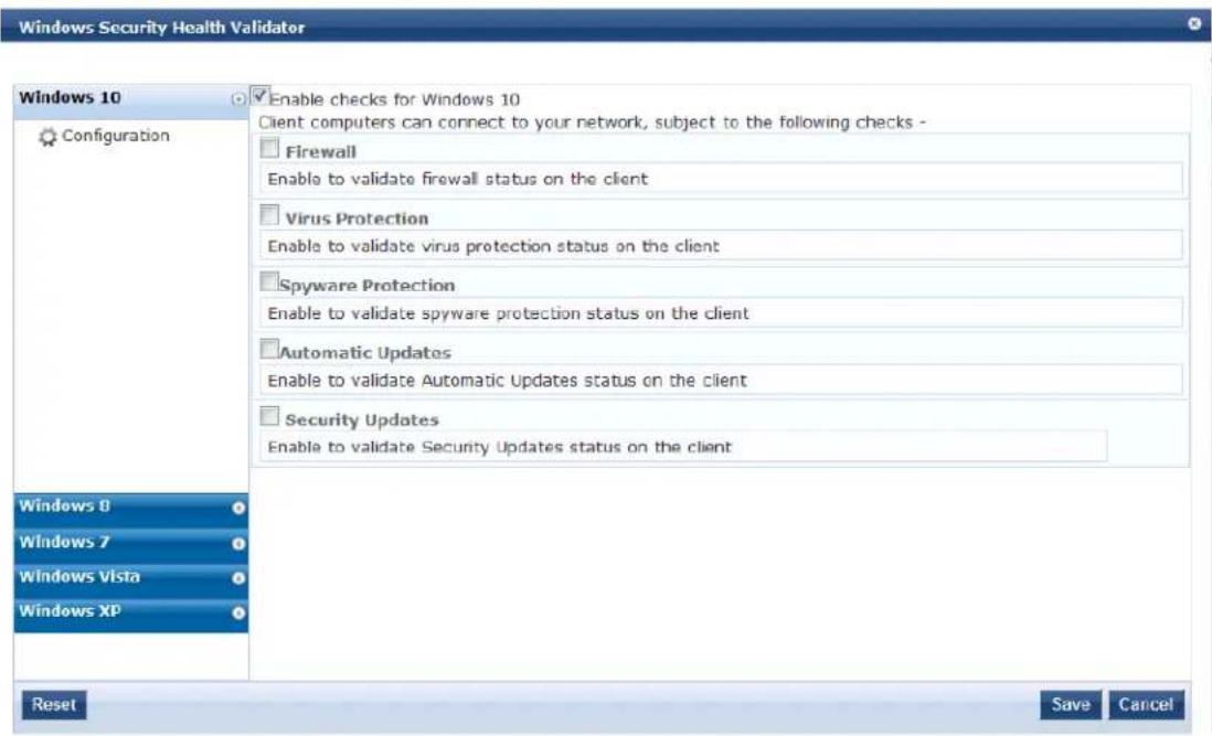
- To enable support of specific operating systems, click the corresponding check boxes.
- Click Save.
You return to the Posture Plugins page where the status of the Windows Security Health Validator plug-in is now Configured.
Configuring Posture Policy Rules
Once you have defined the posture hosts, agents, and plugins, you must configure the rules for the pos policy. To configure posture policy rules, navigate to Configuration > Posture > Posture Policies > Add, and click the Rules tab on the Posture Policies window.
Figure 333: Posture Policy Rules Tab and Rules Editor
The following table describes the Rules Editor configuration parameters:
Table 178: Posture Policy Rules Editor Parameters
| Parameter Description | |
| Select Plugin Checks | Click select one of the following plugin check types for System Health Validators (SHVsPasses all SHV checksPasses one or more SHV checksFails all SHV checksFails one or more SHV checks |
| Select Plugins Select | the plug-in to which the plug-in checks should apply. |
| Posture Token Select | one of the following posture token types. |
Configuring Posture for Services
Policy Manager can forward all or part of the posture data received from the client to a posture server. posture server evaluates the posture data and returns application posture tokens. Policy Manager supports the Microsoft NPS Server for Microsoft NAP integration. To configure the posture for a service, navigate Add Service (Configuration > Services > Add) page. The Posture tab is not enabled by default. To enable posture checking for this service, select the Posture Compliance check box from the More Options field on the Service tab.
You can enable the posture checking for this kind of service, if you deploy any of the following:
• Policy Manager in a Microsoft Network Access Protection (NAP)
• Cisco Network Admission Control (NAC) Framework environment
- Dell hosted captive portal that performs posture checks through a dissolvable agent The following figure displays an example on how to configure a posture at the service level:

The Posture Compliance check box must be selected on the Service tab in order for posture to be enabled.
Figure 334: Posture Features at the Service Level
![Summary Service Authentication Roles Posture Enforcement Posture Policies: Posture Policies: Basic Linux Health Check Remove View Details Modify --Select to Add-- Default Posture Token: UNKNOWN (100) Remediate End-Hosts: Enable auto-remediation of non-compliant end-hosts Remediation URL: http://remediation_internal.us.acme.com Posture Servers: Posture Servers: PS_NPS [RADIUS] [Microsoft NPS] Remove View Details Modify --Select to Add--](/content/2026/05/842116/images/a16244b3ba9598e0b9fff0595abb41c50214669d620be8b8da57b22034695637.jpg)
You can configure the following components of a posture:
Table 179: Posture Features at the Service Level
| Configurable Component | How to Configure |
| Sequence of Posture Policies | Select a policy, then selectMove Up, Move Down, Remove, or View Details.To add a previously configured policy, select from the Select drop-down list, then click Add.To configure a new policy, click the Add link at the top-right corner of theConfiguration > Posture Policies page. For more information, see Configuring Posture Policy Agents and Hosts on page 285.To edit the selected posture policy, click Modify. For more information, see Configuring Posture Policy Agents and Hosts on page 285. |
| Default Posture Token | The default posture token is UNKNOWN (100). You can select the default posture token from the drop-down list. |
| Remediation End-Hosts | Select this check box to enable auto-remediation action on non-compliant endpoints. |
| Remediation URL This URL defines where to send additional remediation information to endpoints. | |
| Sequence of Posture Servers | Select a posture server, then selectMove Up, Move Down, Remove, or View Details.To add a previously configured posture server, select from the Select drop-down list, then clickAdd.To configure a new posture server, clickAddlink at the top-right corner of theConfiguration>Posture Policiespage. For more information, see Adding and Modifying Posture Servers.To edit the selected posture server, clickModify. For more information, see Adding and Modifying Posture Servers. |
| Enable auto-remediation of non-compliant end-hosts | Select theEnable auto-remediation of non-compliant end-hostscheck box to enable the specified remediation server to enable auto-remediation. Remediation server is optional. A popup appears on the client box with the URL of the remediation server. |
Configuring Audit Servers
The W-ClearPass Policy Manager server contains default Nessus (v2.X through v6.x) and Nmap (Network Mapping) servers. For enterprises with existing audit server infrastructure, or with external audit servers, Manager supports these servers externally.
For more information, see:
• Default Audit Servers on page 356
- Custom Audit Servers on page 359
• Post-Audit Rules on page 368
Audit Service Flow Control
Audit servers evaluate posture, role, or both for unmanaged or unmanageable clients. One example is cl that lack an adequate posture agent or an 802.1X supplicant. For example, printers, PDAs, or guest users not be able to send posture credentials or identify themselves.
A Policy Manager Service can trigger an audit by sending a client ID to a pre-configured audit server, an server returns attributes for role mapping and posture evaluation.
Audit servers are configured at a global level. Only one audit server can be associated with a service. The of-control of the audit process is shown in the figure below.
Figure 335: Flow of Policy Manager Auditing Control
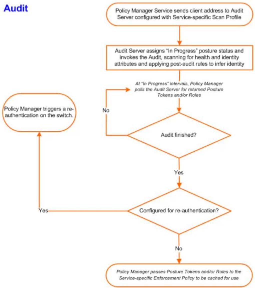
flowchart
graph TD
    A["Policy Manager Service sends client address to Audit Server configured with Service-specific Scan Profile"] --> B["Audit Server assigns "In Progress" posture status and invokes the Audit, scanning for health and identity attributes and applying post-audit rules to infer identity"]
    B --> C{Audit finished?}
    C -->|No| D["At "In Progress" intervals, Policy Manager polls the Audit Server for returned Posture Tokens and/or Roles"]
    D --> E{Regulated for re-authentication?}
    E -->|Yes| F["Policy Manager triggers a re-authentication on the switch"]
    E -->|No| G["No"]
    F --> H["Policy Manager passes Posture Tokens and/or Roles to the Service-specific Enforcement Policy to be cached for use"]
Default Audit Servers
When you configure an audit as part of a Policy Manager service, you can select the default Nessus (Ne Server) or the Nmap Audit configuration.
Adding Auditing to a Service
To configure an audit server for a new service:
- Navigate to Configuration > Services.
The Services page opens.
- Select the Add link in the top-right corner.
The Add Services dialog opens.
-
To display the Audit tab, select the More Options > Audit End-Hosts check box.
-
In the Add Services dialog, select the Audit tab.
The Add Services > Audit dialog opens.
Figure 336: Add Services > Audit Dialog
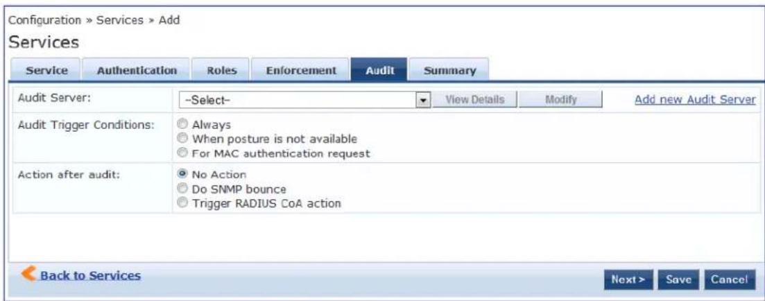
- Complete the fields in the Add Services > Audit tab as described in Table 180, then click Save.
Table 180: Add Services > Audit Dialog Parameters
| Parameter | Action/Description |
| Audit Server | Select a server profile from the list:Nessus Server:Performs vulnerability scanning and returns a Healthy/Quarantine result.Nmap Audit:Performs network port scans. The health evaluation always returns a Healthy result. The port scan gathers attributes that allow determination of role(s) through post-audit rules.You can click the View Details button to view the Policy Manager Entity Details dialog with the summary of audit server details.To view the Summary tab with audit server details, click the Modify button.For Policy Manager to trigger an audit on an end-host, it needs to get the IP address of the end-host. The IP address of the end-host is not available at the time of initial authentication for 802.1X and MAC authentication requests. Policy Manager's DHCP snooping service examines the DHCP request and response packets to derive the IP address of the end-host.For this to work, you need to use this service, Policy Manager must be configured as a DHCP "IP Helper" on your router/switch in addition to your main DHCP server. Refer to your switch documentation for "IP Helper" configuration.To audit devices that have a static IP address assigned, it is recommended that you create a static binding between the MAC address and IP address of the endpoint in your DHCP server. Refer to your DHCP server documentation for configuring static bindings.NOTE:Policy Manager does not issue the IP address; it only examines the DHCP traffic to derive the IP address of the end-host. |
| Audit Trigger Conditions | Select from the following audit trigger conditions:Always:Always perform an audit.When posture is not available:Perform audit only when posture credentials are not available in the request.For MAC Authentication Request:If you select this option, then Policy Manager presents the following three additional settings:For known end-hosts only:Select this option when you want to reject unknown end-hosts and to audit known clients. Known end-hosts are defined as clients that are found in the authentication source(s) associated with this service.For unknown end-hosts only:Select this option when known end-hosts are assumed to be healthy, but you want to establish the identity of unknown end-hosts and assign roles. Unknown end-hosts are end-hosts that are not found in any of the authentication sources associated with this service.For all end-hosts:For both known and unknown end-hosts. |
| Action after audit | Select an Action after audit.Performing an audit on a client is an asynchronous task, which means the audit can be performed only after the MAC authentication request is completed and the client has acquired an IP address through DHCP. Once the audit results are available, there should be a way for Policy Manager to re-apply policies on the network device. This can be accomplished in one of the following ways:No Action:The audit will not apply policies on the network device after this audit.Do SNMP bounce:This option will bounce the switch port or force an 802.1X reauthentication (both done using SNMP). Bouncing the port triggers a new 802.1X/MAC authentication request by the client.If the audit server already has the posture token and attributes associated with client in its cache, it returns the token and the attributes to Policy Manager.Trigger RADIUS CoA action:This option sends a RADIUS CoA command to the network device. |
Modifying Default Audit Servers
To reconfigure default Policy Manager audit servers:
- Navigate to Configuration > Posture > Audit Servers.
Figure 337: Audit Servers Page
![Configuration > Posture > Audit Servers Audit Servers Filter: Name contains Go Clear Filter Name ▲ Description Type 1. [Nessus Server] Nessus server running in the Policy Manager server NES5US 2. [Nmap Audit] Nmap default configuration NMAP Showing 1-2 of 2 Copy Export Delete](/content/2026/05/842116/images/2bb699b0891f6feb7fdaee21173bfb62a3fc833a453549fedcbb0fe1a3f1d7dc.jpg)
- Select an audit server from the list of available servers.
The Edit Audit Servers page opens.
- Modify the profile, plugins, and/or preferences.
• In the Audit tab, you can modify the In-Progress Posture Status and Default Posture Status.
- If you selected a Nessus Server, the Primary Server and Backup Server tabs allow you to specify a scan profile. In addition, when you add a new scan profile, you can select plugins and preferences profile. Refer to Nessus Scan Profiles on page 363 for more information.
The default Policy Manager Nessus audit server ships with approximately 1,000 of the most common used Nessus plugins.
Rules Tab
In the Rules tab, you can create post-audit rules for determining roles based on identity attributes discovered by the audit. For more information on creating post-audit rules, see Post-Audit Rules on page 368.
Custom Audit Servers
This section provides the following information:
■ Adding a Nessus Audit Server on page 360
■ Required Configuration Updates for External Nessus Servers
■ Adding an Nmap Audit Server on page 366
For enterprises with existing audit server infrastructure or preferring custom audit servers, Policy Manage supports Nessus (v2.x through v6.x) and Nmap scans using the NMAP plug-in on external Nessus servers
Adding a Nessus Audit Server
W-ClearPass uses the Nessus audit server interface primarily to perform vulnerability scanning. It returns result of Healthy or Quarantine.
To add a Nessus audit server:
- Navigate to Configuration > Posture > Audit Servers, then click Add.
The Add Audit Servers dialog opens to the Audit tab.
Figure 338: Add Nessus Audit Server > Audit Tab
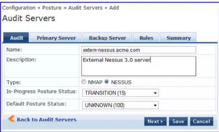
- Specify the Nessus Audit Server > Audit tab parameters as described in Table 181.
Table 181: Add Nessus Audit Server > Audit Tab Parameters
| Parameter Action/Description | |
| Name Specify the | name of the audit server. |
| Description Optionally (and recommended), enter the description that provides additional information about the audit server. | |
| Type | Specify the type of audit server: Nmap (Network Mapper) or Nessus. |
| In-Progress Posture Status | Specify the posture status during audit. |
| Default Posture Status | Specify the posture status if evaluation does not return a condition/action m |
The Primary Server and Backup Server tabs specify connection information for the Nessus audit server.
Figure 339: Add Nessus Audit Server > Primary and Backup Server Tabs
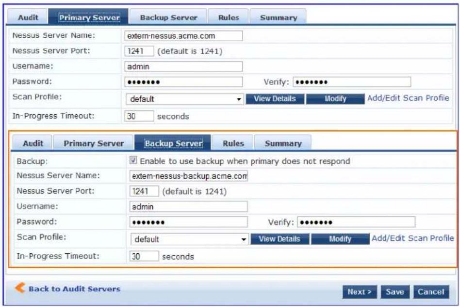
- Specify the Nessus Audit Server > Primary Server tab and Backup Server tab parameters as described in Table 182.
Table 182: Nessus Audit Server > Primary and Backup Server Tabs Parameters
| Parameter Action/Description | |
| Backup | On the Backup Server dialog: For the backup server to be invoked on primary server failover, check the Enable to use backup when primary does not respond check box. |
| Nessus Server Name Enter the name of the Nessus server. | |
| Nessus Server Port Specify the Nessus Server port. The default is 1241. | |
| Username Enter the username for the primary and backup Nessus servers. | |
| Password Enter the password for the primary and backup Nessus servers. | |
| Scan Profile | You can accept the default scan profile or select Add/Edit Scan Profile to create other profiles and add them to the scan profile list. Refer to Scan Profiles on page 363. |
| In-Progress Timeout | Specify the duration (in seconds) before polling for Nmap results. The default is 30 seconds. |
- Configure the audit server Rules.
The Rules tab specifies rules for post-audit evaluation of the request to assign a role. For more information, refer to Post-Audit Rules on page 368.
Modifying a Nessus Audit Server
To modify an existing Nessus audit server:
- Navigate to Configuration > Posture > Audit Server.
The Audit Servers dialog opens.
Figure 340: Selecting a Nessus Audit Server
![Configuration > Posture > Audit Servers Audit Servers Filter: Name contains Go Clear Filter Name △ Description Type 1. [Nessus Server] Nessus server running in the Policy Manager server NESSUS 2. [Nimap Audit] Nimap default configuration NMAP Showing 1-2 of 2 Copy Export Delete Add Import Export All Show 10 records](/content/2026/05/842116/images/4d4fa3e147688095c7c9d96abb125c3e211f8b867f533866bc892ec715da62e6.jpg)
- Select the Nessus audit server you wish to modify.
The Edit Nessus Server dialog opens to the Summary tab, which displays the configuration settings for the selected Nessus server.
Figure 341: Edit Nessus Server > Summary Page
![Configuration > Posture > Audit Servers > Edit - [Nessus Server] Audit Servers - [Nessus Server] Summary Audit Primary Server Backup Server Rules Audit: Name: [Nessus Server] Description: Nessus server running in the Policy Manager server Type: NESSUS In-Progress Posture Status: TRANSITION (15) Default Posture Status: UNKNOWN (100) Primary Server: Nessus Server Name: localhost Nessus Server Port: 1241 (default is 1241) Username: aruba Password: ***** Scan Profile: default In-Progress Timeout: 60 seconds Backup Server: Backup: Disabled Nessus Server Name: - Nessus Server Port: 0 (default is 1241) Username: - Password: - Scan Profile: - In-Progress Timeout: 0 seconds Rules: Rules Evaluation Algorithm: Evaluate all Conditions Role Name](/content/2026/05/842116/images/a8c27a2718eaeae2c00cb3092a8f2cb6d2cbdfedab33038fb41a343d12d16467.jpg)
- Make any necessary configuration changes, then click Save.
Required Configuration Updates for External Nessus Servers
To properly support Nessus server configuration on W-ClearPass servers, you must make the following configuration settings on the external Nessus server:
- On the external Nessus server, set the value for the disable_ntp parameter to no.
For example, on a CENTOS/RHEL server running Nessus, you would enter the following command:
centos# /opt/nessus/sbin/nessuscli fix --set disable_ntp=no
- Restart the Nessus service.
For example:
centos# service nessusd restart
- If the external Nessus server has Transport Layer Security (TLS) enabled, add the Nessus CA Certificate the W-ClearPass Certificate Trust List (see Certificate Trust List on page 681).
You can download the Nessus CA certificate from:
https://<nessus_server_name>:8834/getcert
Nessus Scan Profiles
A scan profile contains a set of scripts (plugins) that perform specific audit functions. To Add/Edit Scan F select Add/Edit Scan Profile (link) from the Primary Server tab of the Nessus Audit Server configuration.
The Nessus Scan Profile Configuration page displays.
Figure 342: Nessus Scan Profile Configuration Page
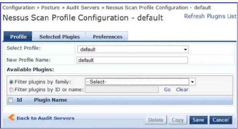
You can refresh the plugins list (after uploading plugins into Policy Manager, or after refreshing the plugin your external Nessus server) by clicking Refresh Plugins List. The Nessus Scan Profile Configuration page provides three views for scan profile configuration:
- The Profile tab identifies the profile and provides a mechanism for selection of plugins:
From the Filter plugins by family drop-down list, select a family to display all available member plugins in the list below. You may also enter the name of a plugin in Filter plugins by ID or name text box.
- Select one or more plugins by enabling their corresponding check boxes (at left). Policy Manager will remember selections as you select other plugins from other plugin families.
■ When finished, click the Selected Plugins tab.
Figure 343: Nessus Scan Profile Configuration - Profile Tab
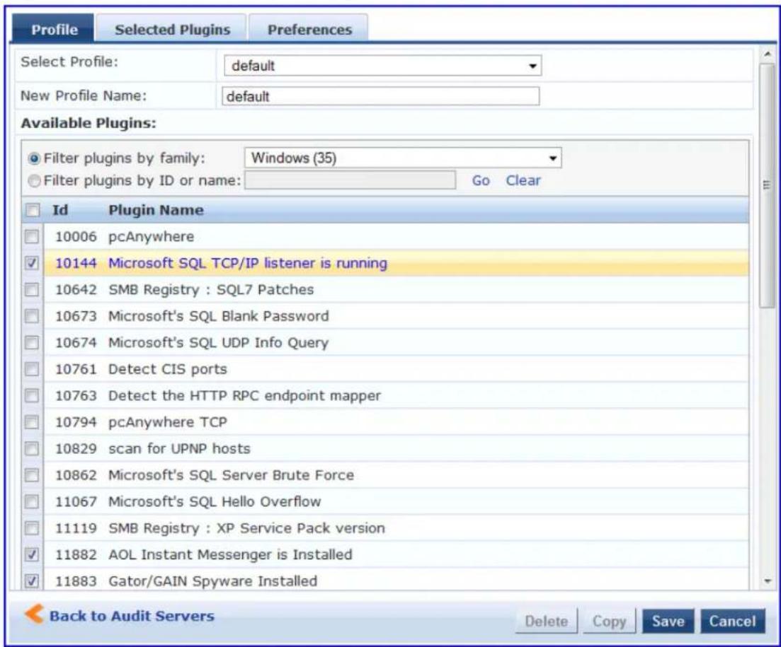
- The Selected Plugins tab displays all selected plugins, plus any dependencies. To display a synopsis of any listed plugin, click on its row.
Figure 344: Nessus Scan Profile Configuration Profile Tab - Plugin Synopsis
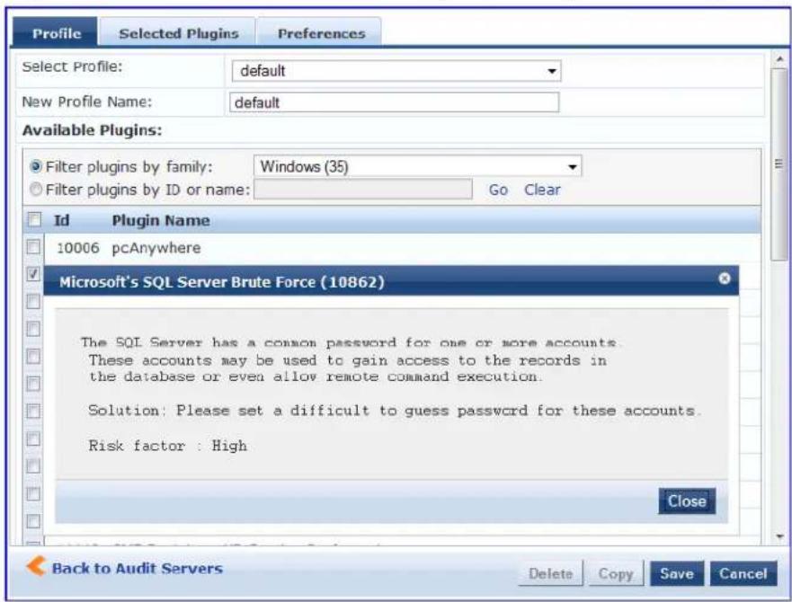
Of special interest is the section of the synopsis entitled Risks. To delete any listed plugin, click on its corresponding trashcan icon. To change the vulnerability level of any listed plugin, click on the link to change the level to one of HOLE, WARN, or INFO. This action tells Policy Manager the vulnerability level that is considered to be assigned QUARANTINE status.
Figure 345: Nessus Scan Profile Configuration - Selected Plugins Tab
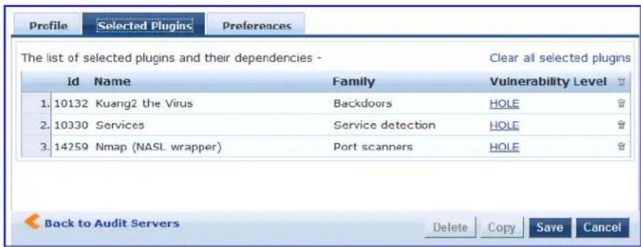
Figure 346: Nessus Scan Profile Configuration Selected Plugins Tab - Vulnerability Level
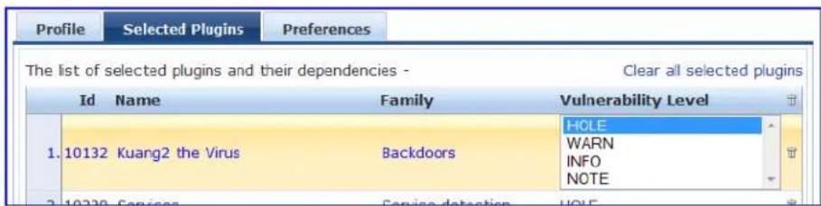
For each selected plugin, the Preferences tab contains a list of fields that require entries.
In many cases, these fields will be pre-populated. In other cases, you must provide information required operation of the plugin.

By way of example of how plugins use this information, consider a plugin that must access a particular in order to determine some aspect of the client's status; in such cases, login information might be amor preference fields.
Figure 347: Nessus Scan Profile Configuration - Preferences Tab
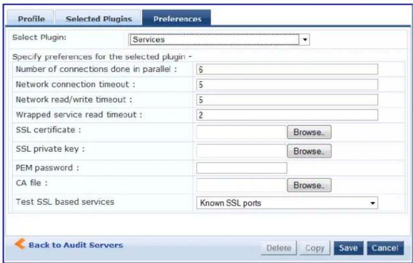
After saving the profile, plugin, and preference information for your new (or modified) plugin, you can go Primary/Backup Servers tabs and select it from the Scan Profile drop-down list.
Adding an Nmap Audit Server
To create an Nmap (Network Mapping) audit server:
- Navigate to the Configuration > Posture > Audit Servers page, then click Add.
- From the Audit tab, select the NMAP radio button in the Type field.
Policy Manager uses the Nmap audit server interface exclusively for network port scans.
■ The Health evaluation always returns a status of Healthy.
The port scan gathers attributes that allow determination of role(s) through post-audit rules.
Audit Tab
You can use the Audit tab to identify the server and define configuration details. Figure 348 shows an example of the Audit tab:
Figure 348: NMAP Audit Server > Audit Tab
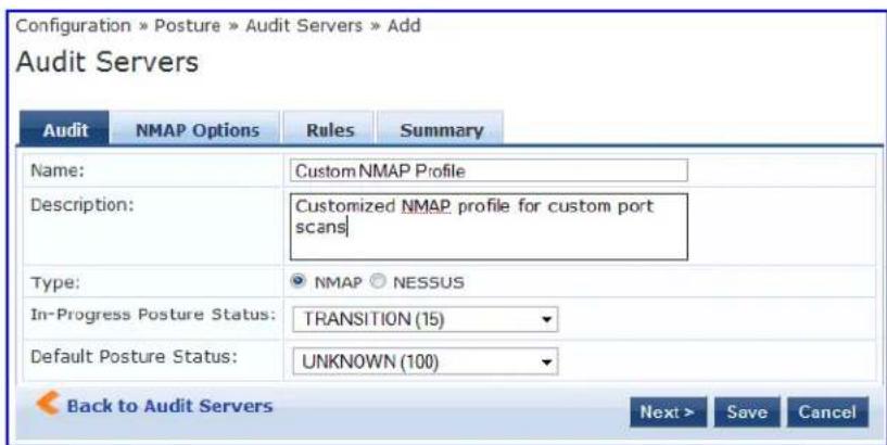
The following table describes the parameters configured in the Audit tab:
Table 183: Audit Tab Parameters
| Parameter Action/Description | |
| Name Enter the name of the NMAP audit server. | |
| Description Optionally (and recommended), enter the description of the Nmap audit server. | |
| Type Select NMAP. | |
| In-Progress Posture Status | Specify the posture status during audit. |
| Default Posture Status | Select the posture status if evaluation does not return a condition/action match. |
NMAP Options Tab
You can use the NMAP Options tab to specify the type of scan configuration.
Figure 349: Nmap Server > NMAP Options Tab
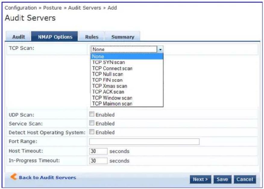
Table 184: NMAP Options Tab
| Parameter Action/Description | |
| TCP Scan Specify the type of TCP scan:TCP SYN scanTCP Connect scanTCP Null ScanTCP FIN scanTCP Xmas scanTCP ACK scanTCP Window scanTCP Maimon scanRefer to Nmap documentation for more information on the TCP scan options.Nmap option:scanflags. | |
| UDP Scan To enable UDP (User Datagram Protocol) scanning, check the UDP Scan check box.Nmap option:sU. | |
| Service Scan | To enable Service scanning, check the Service Scan check box.Nmap option:sV. |
| Detect Host Operating System | To enable host OS detection, check the Detect Host Operating System check box.NMAP option:A. |
| Port Range Specify the range of ports to scan.NMAP option:p. | |
| Host Timeout | Specify the time in seconds for the target host to timeout.Nmap option:host-timeout |
| In-Progress Timeout | Specify the duration (in seconds) before polling for Nmap results. |
Rules Tab
The Rules tab specifies rules for post-audit evaluation of the request to assign a role. For details, refer to Post-Audit Rules on page 368.
Post-Audit Rules
The Audit Servers > Rules dialog specifies rules for post-audit evaluation of the request to assign a role.
Figure 350: All Audit Server Configurations > Rules Dialog
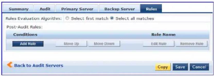
Table 185: All Audit Server Configurations > Rules Dialog Parameters
| Parameter Action/Description | |
| Rules Evaluation Algorithm | Select first matched rule and return the role or Select all matched rules and return a set of roles. |
| Add Rule When you | add a rule, the Rules Editor opens. See below for details. |
| Move Up/Down Reorder the rules as necessary. | |
| Edit Rule Opens the | selected rule in Edit mode. |
| Remove Rule Removes the selected rule. | |
Figure 351: All Audit Server Configurations > Rules Editor
![Rules Editor Conditions Matches ○ ANY or ○ ALL of the following conditions: Name Operator Value 1. OS-Info CONTAINS Linux 2. 3. Audit-Status Device-Type Output-Msgs Network-Apps Mac-Vendor CACS Help Desk] 4. OS-Info Open-Ports Act Ro Save Cancel](/content/2026/05/842116/images/19f251d71a6cd259cc8b68239ab476478dff4ed3c49f0c17cd381851f189d2ca.jpg)
Table 186: All Audit Server Configurations > Rules Editor Parameters
| Parameter Description | |
| Conditions The Conditions list includes five dictionaries:Audit-StatusDevice-TypeOutput-MsgsMAC-VendorNetwork-AppsOpen-PortsOS-InfoFor more information, refer to Namespaces on page 919. | |
| Actions | The Actions list includes the names of the roles configured in Policy Manager. |
| Save To commit a Condition/Action pairing, click Save. | |
This chapter describes the following topics:
- Configuring Enforcement Policies on page 371
- Configuring Enforcement Profile on page 373
Policy Manager controls network access by sending a set of access-control attributes to the request-origin Network Access Device (NAD).
Policy Manager sends these attributes by evaluating an enforcement policy associated with the service.
Each enforcement policy contains a rule or set of rules for matching conditions (role, posture, and time) actions (enforcement profiles).
For a general overview of network access enforcement policies, see Enforcement Architecture and Flow on page 1.
Configuring Enforcement Policies
One and only one enforcement policy can be associated with each service. Enforcement policies can be in one of two ways:
• From Configuration > Enforcement > Enforcement Policies.
- From the Configuration > Services page as part of the flow of the Add Service wizard.
Figure 352: Enforcement Policies Page
![Configuration » Enforcement » Policies Enforcement Policies Filter: Name ▼ contains ▼ Go Clear Filter Show 10 records Name ▲ Type Description 1. [Admin Network Login Policy] TACACS Enforcement policy controlling access to Policy Manager Admin 2. Agent-enforcement WEBAUTH 3. [AirGroup Enforcement Policy] RADIUS Enforcement policy controlling access for AirGroup devices 4. [Aruba Device Access Policy] TACACS Enforcement policy controlling access to Aruba device 5. Automation_Enforcement RADIUS 6. Automation_Enf_Unknown RADIUS 7. AUTO_SNMP_ENF WEBAUTH 8. Copy_of_WLAN-SMU Enfor CPPM2 RADIUS 9. Guest - MAC Caching - Limit 1 Device. RADIUS Limits guests to maximum 1 device for MAC caching purposes 10. Guest - MAC Caching - Limit 2 Devices RADIUS Limits guests to maximum 2 devices for MAC caching purposes Showing 1-10 of 45 ▶ Copy Export Delete](/content/2026/05/842116/images/f1fa182031b8abcc26c71f958c01542d1ad8d223e6976d3d12aa6eed6bc363ec.jpg)
- To add a new enforcement policy, click Add.
The Add Enforcement Policy page opens to the Enforcement tab:
Figure 353: Add Enforcement Policy > Enforcement Tab
![Configuration » Enforcement » Policies » Add Enforcement Policies Enforcement Rules Summary Name: Employee Access Enforcement Description: Enforcement policy for employee access Enforcement Type: RADIUS TACACS+ WEBAUTH (SNMP/Agent/CLI/CoA) Application Default Profile: [Allow Access Profile] View Details Modify Add new Enforcement Profile Back to Enforcement Policies Next > Save Cancel](/content/2026/05/842116/images/d7475f284875b947521868060da5025169466e45ad9e1b3367b574eeace5a43d.jpg)
- Specify the Add Enforcement Policy > Enforcement parameters as described in the following table:
Table 187: Add Enforcement Policy > Enforcement Tab Parameters
| Parameter Action/Description | |
| Name Enter the name of this enforcement policy. | |
| Description Enter a useful description of this enforcement policy (recommended). | |
| Enforcement Type Select one of the following enforcement types:RADIUSTACACS+WebAuth (SNMP/CLI)/CoAApplicationEventBased on this selection, theDefault Profiledrop-down lists the associated enforcement profiles.NOTE:Web-based Authentication or WebAuth (HTTPS) is the mechanism used by authentications performed via a browser, and authentications performed via W-ClearPass OnGuard.Both SNMP- and CLI- (SSH/Telnet) based enforcement profiles can be sent to the network device based on the type of device and the use case. | |
| Default Profile An enforcement policy applies conditions (roles, health, and time attributes) against specific values associated with those attributes to determine the enforcement profile. If none of the rules matches, Policy Manager applies the default profile.To add a new profile, clickAdd New Enforcement Profile. |
- In the Rules tab, click New Rule to display the Rules Editor:
Figure 354: Add Enforcement Policy > Rules Editor
![Enforcement Rules Summary Rules Evaluation Algorithm: Select first match Select all matches Enforcement Policy Rules: Conditions Actions 1. (Tips: Role MATCHES_ANY [Employee]) [RADIUS] [Allow Access Profile] 2. (Tips: Role EQUALS [Guest]) [RADIUS] [Allow Access Profile] AND (Tips: Posture EQUALS HEALTHY [0]) [RADIUS] [Allow Access Profile] Add Rule Move Up Move Down Edit Rule Remove Rule Back to Enforcement Policies Next > Save Cancel](/content/2026/05/842116/images/2ff40aa15348401ec46579756bcfd7ea473979d2bb423c81d66e60680ca4e1e3.jpg)
- Specify the Add Enforcement Policy > Rules tab parameters as described in the following table:
Table 188: Add Enforcement Policy: Rules Editor
| Field Action/Description | |
| Add Rule Click this button to bring up the Rules Editor. | |
| Move Up/Down | To reorder the rules in the enforcement policy, select an enforcement policy rule, then click Move Up or Move Down. |
| Remove Rule | To delete a rule, select the rule, then click Remove Rule. |
Table 189: Add Enforcement Policy: Rules Editor
| Field Description | |
| Conditions/Enforcement Profiles | Select conditions for this rule. For each condition, select a matching action (enforcement profile).NOTE:A condition in an enforcement policy rule can contain attributes from the following namespaces: Tips:Role, Tips:Posture, and Date.NOTE:The value field for the Tips:Role attribute can be a role defined in Policy Manager, or a role fetched from the authorization source.You can enter role names fetched from the authorization source free-form in the field. To commit the rule, click Save. |
| Enforcement Profiles If | the rule conditions match, attributes from the selected enforcement profiles are sent to the Network Access Device. If a rule matches and there are multiple enforcement profiles, the enforcement profile disambiguation rules apply. Refer to Configuring Enforcement Profile on page 373 for a list of the default profiles. |
Configuring Enforcement Profile
- Adding an Enforcement Profile
- Modifying an Existing Enforcement Profile
You can configure Policy Manager enforcement profiles globally, but they must be referenced to an enforcement policy that is associated with a service.
For information about configuring specific enforcement profiles, see:
• Agent Enforcement Profile on page 376
• Agent Script Enforcement Profile on page 379
- Dell Downloadable Role Enforcement Profile on page 383
• Dell RADIUS Enforcement Profile on page 393
- Cisco Downloadable ACL Enforcement Profile on page 395
• Cisco Web Authentication Enforcement Profile on page 397
• W-ClearPass Entity Update Enforcement Profile on page 399
• CLI-Based Enforcement Profile on page 401
• Filter ID Based Enforcement Profile on page 403
- Generic Application Enforcement Profile on page 405
- HTTP Based Enforcement Profile on page 406
• RADIUS Based Enforcement Profile on page 407
• RADIUS Change of Authorization (CoA) Profile on page 409
- Session Restrictions Enforcement Profile on page 413
• SNMP-Based Enforcement Profile on page 418
• TACACS+ Based Enforcement Profile on page 419
• VLAN Enforcement Profile on page 422
Adding an Enforcement Profile
To add an enforcement profile:
- Navigate to Configuration > Enforcement > Profiles.
The Enforcement Profiles page opens:
Figure 355: Enforcement Profiles Page
![Configuration » Enforcement » Profiles Enforcement Profiles Filter: Name ▼ contains ▼ Go Clear Filter Show 10 records Name ▲ Type Description 1. [Aerohive - Terminate Session] RADIUS_CoA System-defined profile to disconnect user (Aerohive) 2. Agent-Healthy Agent 3. Agent-unhealthy Agent 4. [AirGroup Personal Device] RADIUS System-defined profile for an AirGroup personal device request 5. [AirGroup Response] RADIUS System-defined profile for any AirGroup request 6. [AirGroup Shared Device] RADIUS System-defined profile for an AirGroup shared device request 7. [Allow Access Profile] RADIUS System-defined profile to allow network access 8. [Allow Application Access Profile] Application System-defined profile to allow access to application 9. [Aruba TACACS read-only Access] TACACS System-defined profile for read-only access to Aruba device 10. [Aruba TACACS root Access] TACACS System-defined profile for root access to Aruba device Showing 1-10 of 171 ▶ Copy Export Delete](/content/2026/05/842116/images/70504b9828a6fd96646902b85675451ac8a67b00885c4b8cff398d066f8d2ba7.jpg)
- Click Add at the top-right corner.
The Add Enforcement Profile dialog opens.
Figure 356: Add Enforcement Profile Dialog
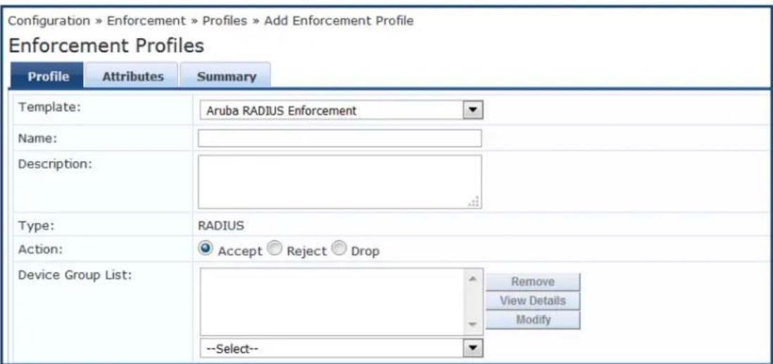
The following table describes the default set of enforcement profiles included with Policy Manager:
Table 190: Default Enforcement Profiles
| Enforcement Profile Available for These Enforcement Types | |
| [Aerohive - Terminate Session] RADIUS_CoA | |
| [AirGroup Personal Device] RADIUS | |
| [AirGroup Response] RADIUS | |
| [AirGroup Shared Device] RADIUS | |
| [Allow Access Profile] RADIUS | |
| [Allow Application Access Profile] Application | |
| [Aruba TACACS read-only Access] | TACACS |
| [Aruba TACACS root Access] | TACACS |
| [Aruba Terminate Session] | RADIUS_CoA |
| [Cisco - Bounce-Host-Port] | RADIUS_CoA |
| [Cisco - Disable Host-Port] | RADIUS_CoA |
| [Cisco - Reauthenticate-Session] | RADIUS_CoA |
| [Cisco - Terminate-Session] | RADIUS_CoA |
| [Deny Access Profile] | RADIUS |
| [Deny Application Access Profile] | Application |
| [Drop Access Profile] RADIUS | |
| [Handle AirGroup Time Sharing] HTTP | |
| [HP - Terminate Session] RADIUS_CoA | |
| [Juniper Terminate Session] RADIUS_CoA | |
| [Motorola - Terminate Session] RADIUS_CoA | |
| [Operator Login - Admin Users] Application | |
| [Operator Login - Local Users] | Application |
| [TACACS API Admin] | TACACS |
| [TACACS Deny Profile] | TACACS |
| [TACACS Help Desk] | TACACS |
| [TACACS Network Admin] | TACACS |
| [TACACS Read-only Admin] | TACACS |
| [TACACS Receptionist] | TACACS |
| [TACACS Super Admin] | TACACS |
| [Trapeze - Terminate Session] | RADIUS_CoA |
| [Update Endpoint Known] | Post-Authentication |
Modifying an Existing Enforcement Profile
To modify an existing enforcement profile:
- Navigate to the Configuration > Enforcement > Profiles page.
- Click the name of the profile in the Enforcement Profile list that you wish to modify.
The Edit Enforcement Profile dialog for the selected profile opens. The parameters vary according to which profile is selected.
- Make the necessary changes in the Profile and Attributes dialogs, then click Save.
Agent Enforcement Profile
To configure profile and attribute parameters for an Agent Enforcement profile:
- Navigate to Configuration > Enforcement > Profiles.
The Enforcement Profiles page opens.
- Click Add.
The Add Enforcement Profiles > Profile tab opens.
- From the Template drop-down, select Agent Enforcement.
The following figure displays the Agent Enforcement > Profile dialog:
Figure 357: Agent Enforcement > Profile Tab
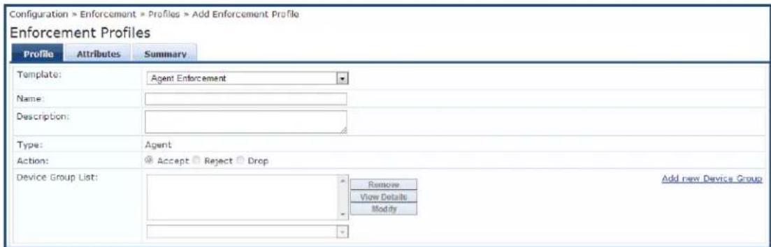
- Specify the Add Agent Enforcement > Profile parameters as described in the following table:
Table 191: Add Agent Enforcement > Profile Parameters
| Parameter Action/Description | |
| Template | Select the template from the drop-down list. In this context, select Agent Enforcement. |
| Name Enter the name of the enforcement profile. | |
| Description Optionally, enter a description of the enforcement profile (recommended). | |
| Type This field is populated automatically with type Agent. | |
| Action By default, this field is disabled. It is enabled only when RADIUS type is selected. | |
| Device Group List | Select a device group from the drop-down list. The list displays all configured device group All configured device groups are listed in the Configuration > Network > Device Group page. After you add one or more device groups, you can select a group and take one following actions:To delete the selected Device Group List entry, click Remove.To see the device group parameters, click View Details.To change the parameters of the selected device group, click Modify. |
| Add New Device Group | To add a new device group, click the Add New Device Group link. For more information, see Adding and Modifying Device Groups on page 474. |
Configuring Agent Enforcement Attributes
Use the Attributes tab to configure the attribute name and attribute value for each attribute you add.
Figure 358: Agent Enforcement > Attributes Dialog
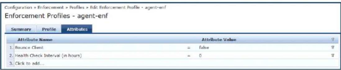
Specify the Agent Enforcement > Attributes parameters as described in the following table:
Table 192: Agent Enforcement > Attributes Tab Parameters
| Attribute Action/Description | |
| Attribute Name | Select one of the following attribute names:·Bounce Client:To bounce the network interface, set the value to True.·Message:Enter the message that needs to be notified on the endpoint.·Session Timeout (in seconds):Configure the agent session timeout interval to periodically evaluate the endpoint's health.OnGuard Agent performs health checks after the specified session timeout interval an updates the health status of the endpoint in Policy Cache.You can specify the session timeout interval from 60 to 600 seconds. The default value is 0. Note that setting the lower value for the session timeout interval results in numerous authentication requests in the Access Tracker page.·Health Check Interval (in hours):Specify the health-check interval value in hours for different Agent Enforcement Profiles for different users. The allowed range is of 0 to 1000 hours.NOTE:The value of the Policy result cache timeout parameter (Administration > Server Manager > Server Configuration > Cluster-Wide Parameters > General tab) must be greater than the highest value of all the Health Check Interval (in hours) values. Note the following information when you set the Health Check Interval parameter:·You can set this parameter if OnGuard mode is set to Health only.·This parameter is valid only for wired and wireless interface types.·This parameter is not applicable for the OnGuard Dissolvable Agent, VPN, and Other interface types.·Enable to hide Retry button:To hide the Retry button in the OnGuard Agent, set the value to True.·Enable to hide Logout button:To hide the Logout button in the OnGuard Agent, set the value to True.·Enable to hide Quit option:To hide all Quit options in the OnGuard Agent, set the value to True.·Bounce Delay (in seconds):When Bounce Delay is configured, the network interface is bounced after the specified delay.·Show Custom UI for Custom Scripts:Click the check box to set this attribute to True and enable the OnGuard Agent Remediation User Interface for Custom Scripts (for related Information, refer to the Custom User Interface parameter in Creating OnGuard Custom Web Pages on page 702).·SDK Type:Allows you to specify the V3 or V4 OnGuard Detection SDK (for related information, see Upgrading From OnGuard Plugin Version 1.0 to 2.0 on page 740). |
| Attribute Value | The value set depends on the selected Attribute Name. |
Summary Information
The Summary tab summarizes the parameters configured in the Profile and Attribute tabs.
Figure 359: Agent Enforcement > Summary Tab
![Enforcement Policies - Agent-enforcement Summary Enforcement Rules Enforcement: Name: Agent-enforcement Description: Enforcement Type: WEBAUTH Default Profile: Agent-initial Rules: Rules Evaluation Algorithm: First applicable Conditions Actions 1, (Tips:Posture EQUALS HEALTHY [0]) Agent-healthy](/content/2026/05/842116/images/627ac82d13da4b669ce07f9c9205dc7be5c9a06a82efe3816a2fd4126bf206ca.jpg)
Agent Script Enforcement Profile
This section provides the following information:
- Introduction
- Configuring the Agent Script Enforcement Profile
- Configuring Agent Script Enforcement Attributes
• Viewing the Configuration Summary
Introduction
Agent Script Enforcement profiles allow execution of custom scripts on endpoint devices as part of agent enforcement. All the details of custom script configuration, such as the path of the custom script, the command to be executed, execution level, and so on, are configured in the Agent Script Enforcement program. You can select multiple Agent Script Enforcement Profiles in a rule in an enforcement profile. OnGuard A executes them one after another.
The Agent Script Enforcement profile is currently supported only with the OnGuard Agent for Windows.
OnGuard Agent applies the Agent Script Enforcement profile (that is, it executes a custom script) after fir applying Agent Enforcement profiles (that is, after Agent Bounce is executed, if configured).
While applying an Agent Script Enforcement profile, OnGuard Agent does not check to see if a script is running. It is possible for OnGuard Agent to launch the script multiple times if a previously launched script still running. This can occur if OnGuard Agent performs multiple health checks (either manually triggered caused by a change in health status). The script exits after performing its task.
Mandatory Agent Script Attributes
The following attributes are mandatory when configuring Agent Script Enforcement:
• Path of the Script
• Command to Execute
- Execution Level
Optional Agent Script Attributes
The following attributes are optional when configuring Agent Script Enforcement:
• SHA256 Checksum
- Wait Time (Seconds) Before Executing Script
• Pass Health Evaluation Results to Script
- Success Message
- Failure Message
- Progress Message
- Description
- Download URL
Configuring the Agent Script Enforcement Profile
To configure an Agent Script Enforcement profile:
- Navigate to Configuration > Enforcement > Profiles.
The Enforcement Profiles page opens.
- Click Add.
The Add Enforcement Profiles dialog opens to the Profile tab.
Figure 360: Agent Script Enforcement > Profile Dialog
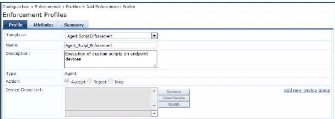
- Specify the Add Agent Script Enforcement > Profile parameters as described in the following table:
Table 193: Add Agent Script Enforcement > Profile Parameters
| Parameter Action/Description | |
| Template Select the Agent Script Enforcement template. | |
| Name Enter the name of the enforcement profile. | |
| Description Optionally, enter a description of the enforcement profile (recommended). | |
| Type | This field is populated automatically with type Agent. |
| Action | This parameter is disabled because it is not applicable to the Agent Script Enforcement Profile. |
| Device Group List | This parameter is disabled because it is not applicable to the Agent Script Enforcement |
| Add new Device Group | This parameter is disabled because it is not applicable to the Agent Script Enforcement |
Configuring Agent Script Enforcement Attributes
Use the Attributes tab to configure the attribute name and attribute value for each attribute you add.
The following figure displays the Agent Enforcement > Attributes dialog:
Figure 361: Agent Script Enforcement > Attributes Dialog
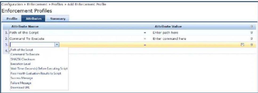
Specify the Agent Script Enforcement > Attributes parameters as described in the following table:
Table 194: Agent Script Enforcement > Attributes Parameters
| Attribute Action/Description | |
| Attribute Name | Select one of the following attribute names:Path of the Script: Complete the path of the script/program, including the filename. This attribute checks for the existence of a file on an endpoint device and also verifies the SHA256 Checksum.Command to Execute: Specify the complete command that OnGuard Agent should execute. You can use the command to launch scripts or pass command line arguments. For example, to launch VBScript (InstallHotfixes.vbs) and pass All as an argument, you would enter the following:cscript /nologo C:\Test\InstallHotfixes.vbs AllIf it is not required to pass arguments, set the value of this attribute to the same value specified for Path of the Script.SHA256 Checksum: Specify the SHA256 checksum of the script/program. This attribute accepts comma-separated multiple SHA256 checksums to allow execution of different versions of same script/program.Execution Level: The attribute values are: User and System.To launch the script/program as the current logged-on user, select User.To launch the script/program as the system user with admin rights, select System.Wait Time (Seconds) Before Executing Script: Specify the time (in seconds) after which OnGuard Agent should launch the script/program.When Wait Time Before Executing Script is configured, the OnGuard Agent does not process events such as Interface Up/Interface Down and health changes during the wait time.Pass Health Evaluation Results to Script: Check the check box (which sets the value to true) to enable OnGuard Agent to pass health evaluation results to the script/program as an argument. The default is false.When the Pass Health Evaluation Results to Script attribute is set to true, OnGuard Agent passes health evaluation results to the script in a URL Encoded JSON format.URL Encode replaces double quotes, spaces, and Unicode characters with their ASCII value in %XX format. For example, spaces are replaced by %20 and double quotes are replaced by %22.Success Message: Enter the message to be shown to the end user when the script/program is launched successfully.Failure Message: Enter the message to be shown to the end user when execution of the script/program fails.Progress Message: This message will be shown on the OnGuard Progress Page (see Creating OnGuard Custom Web Pages on page 702) while OnGuard Agent is executing the custom script and states what action is being performed.Description: Provides a description of the custom UI window or script.Download URL: If the script/program configured in the Path of the Script attribute is not present on the client machine, enter the URL of the remote server from which OnGuard Agent can download the script/program.OnGuard Agent supports downloading scripts only from HTTP and HTTPS URLs. For HTTPS URLs, OnGuard skips server certificate verification.Also, OnGuard Agent does not support downloading files from URLs that require credentials. |
| Attribute Value | The Attribute Value set depends on the selected Attribute Name. |
Viewing the Configuration Summary
The Summary page summarizes the parameters configured in the Profile and Attribute tabs.
The following figure displays the Agent Script Enforcement > Summary page:
Figure 362: Agent Script Enforcement > Summary Dialog
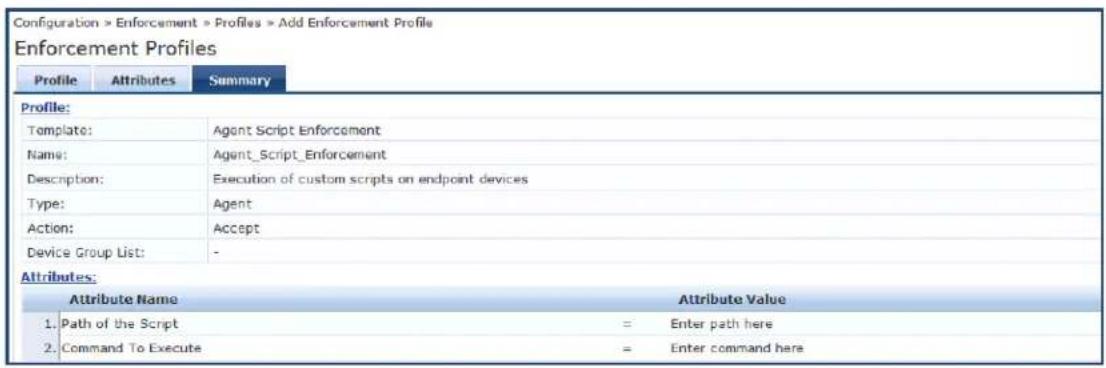
Dell Downloadable Role Enforcement Profile
• Profile Configuration on page 383
• Role Configuration Mode: Standard on page 385
- Adding a Stateless Access Control List on page 390
- Adding a Session Access Control List on page 390
- Adding an Ethernet/MAC Access Control List on page 391
• Role Configuration Mode: Advanced on page 392
• Summary Information on page 393
Profile Configuration
Use the Profile tab to configure the template, type of the profile, and the device group list, as well as specifying the Role Configuration Mode—Standard or Advanced.
- Standard mode: User-provided options to configure individual components of a role (for example, Policer Profile, Stateless ACL configuration, etc.). The user role is generated based on components added to the configuration.
- Advanced mode: You can enter the entire role configuration as a text under a single attribute.
To configure the Dell Downloadable Role Enforcement Profile:
- Navigate to Configuration > Enforcement > Profiles.
The Enforcement Profiles page opens in Standard Role Configuration Mode.
Figure 363: Dell Downloadable Role Enforcement > Profile Page (Standard Mode)
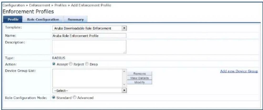
- Specify the Dell Downloadable Role Enforcement > Profile parameters as described in the following table:
Table 195: Dell Downloadable Role Enforcement > Profile Parameters
| Parameter Action/Description | |
| Template Select the Dell | Downloadable Role Enforcement template. |
| Name Enter the name of | the profile. . |
| Description Enter a description of the profile. | |
| Type This field is automatically populated with: RADIUS. | |
| Action | Click Accept, Reject, or Drop to define the action taken on the request. The default action is Accept. |
| Device Group List | Select a device group from the drop-down list. The list displays all configured device groups. All configured device groups are listed in the Configuration > Network Device Groups page. After adding one or more device group(s), you can select group and perform one of the following actions:To delete the selected Device Group List entry, click Remove.To see the device group parameters, click View Details.To change the parameters of the selected device group, click Modify. |
| Add New Device Group | To add a new device group, click the Add New Device Group link. For more information, see Adding and Modifying Device Groups on page 474. |
| Role Configuration Mode | Select one of the following modes:Standard: TBDAdvanced: TBD |
Role Configuration Mode: Standard
When Role Configuration is set to Standard (the default), the Role Configuration tab appears.
The fields on the Role Configuration tab require you to select a link to launch a new page where you set role configuration profiles and related parameters.
Figure 364: Dell Downloadable Role Enforcement Profile > Role Configuration Page
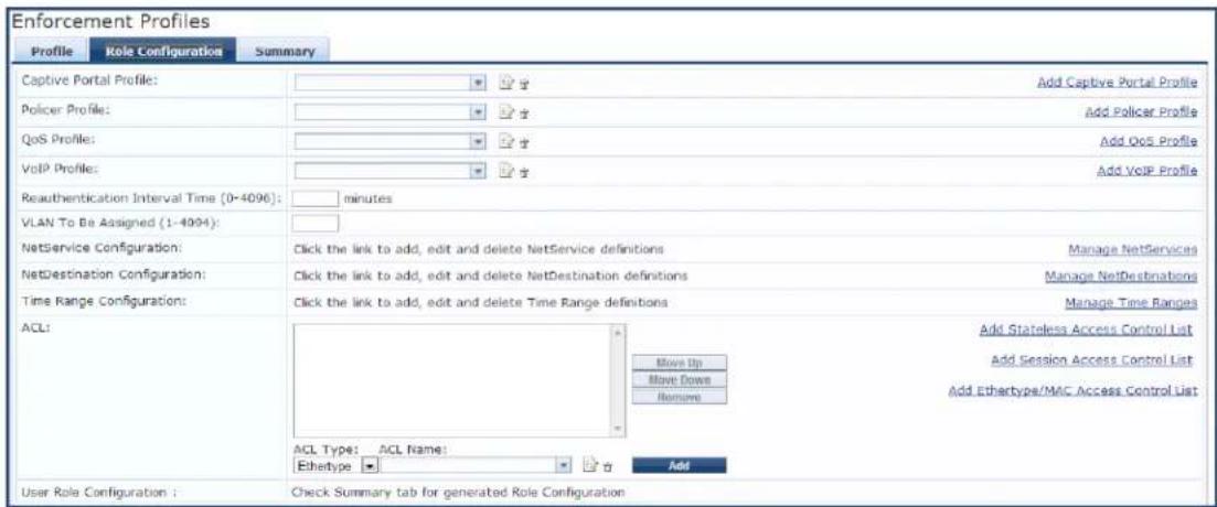
The following table describes the Role Configuration parameters:
Table 196: Role Configuration Parameters
| Parameters Action/Configuration | |
| Captive Portal Profile | Select the captive portal profile from the drop-down list if already configured. Click the Add Captive Portal Profile link to add a new captive portal profile. For more information, see Captive Portal Profile on page 386. |
| Policer Profile | Select the policer profile from the drop-down list if already configured. Click Add Policer Profile link to add a new policer profile. For more information, see Policer Profile on page 387. |
| QoS Profile | Select the QoS profile from the drop-down list if already configured. Click Add QoS Profile link to add a new QoS profile. For more information, see QoS Profile on page 387. |
| VoIP Profile | Select the VoIP profile from the drop-down list if already configured. Click Add VoIP Profile link to add a new VoIP profile. For more information, see VoIP Profile on page 387. |
| Reauthentication Interval Time (0-4096) | Enter the number of minutes between reauthentication intervals. You can select the range between 0 to 4096 minutes. |
| VLAN To Be Assigned (1-4904) | Enter a number between 1 and 4094 that defines when the VLAN is to be assigned. |
| NetService Configuration | Select the Manage NetServices link to add, edit, and delete the NetService definitions. For more information, see NetService Configuration. |
| NetDestination Configuration | Select the Manage NetDestinations link to add, edit, and delete the NetDestinations definitions. For more information, see NetDestination Configuration. |
| Time Range Configuration | Select the Manage Time Ranges link to add, edit, and delete time range definitions. For more information, see Time Range Configuration. |
| NAT Pool Configuration | Select the Manage NAT Pool link to add, edit and delete NAT Pool definitions. For morfe information, see NAT Pool Configuration. |
| ACL Type Select | from the following ACL types:EthertypeMACSessionStateless |
| ACL Name Click | the name of the ACL type.To move the ACL Name to the ACL field, click Add.To modify the order of the names in the ACL list, click Move Up, Move Down.To delete an ACL from the list, click Remove. |
| User Role Configuration | Check the Summary tab for the generated role configuration. |
Captive Portal Profile
To define the Captive Portal Profile:
- Click the Add Captive Portal Profile link.
The Add Captive Portal Profile dialog opens:
Figure 365: Add Captive Portal Configuration Profile
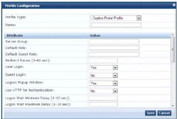
- Enter a name of the profile and configure the required attributes.
Policer Profile
To define a Policer Profile:
- Click the Add Policer Profile link.
The Add Policer Profile dialog opens:
Figure 366: Add Policer Configuration Profile
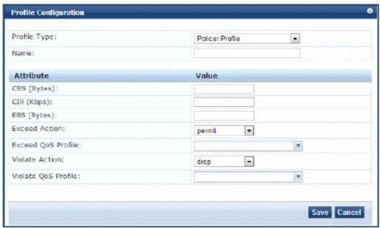
- Enter a name of the profile and configure the required attributes.
QoS Profile
To define a QoS Profile:
- Click the Add QoS Profile link.
The Add QoS Profile opens:
Figure 367: Add QosProfile Configuration Profile
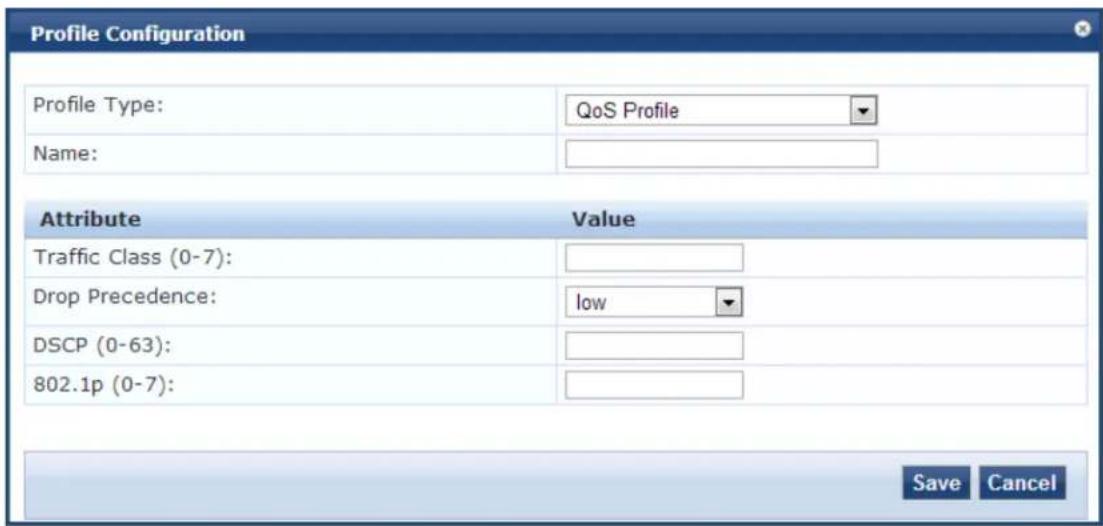
- Enter a name of the profile and configure the required attributes.
VoIP Profile
To define a VoIP Profile:
- Click the Add VoIP Profile link.
The Add VoIP Profile dialog opens:
Figure 368: Add VoIP Configuration Profile
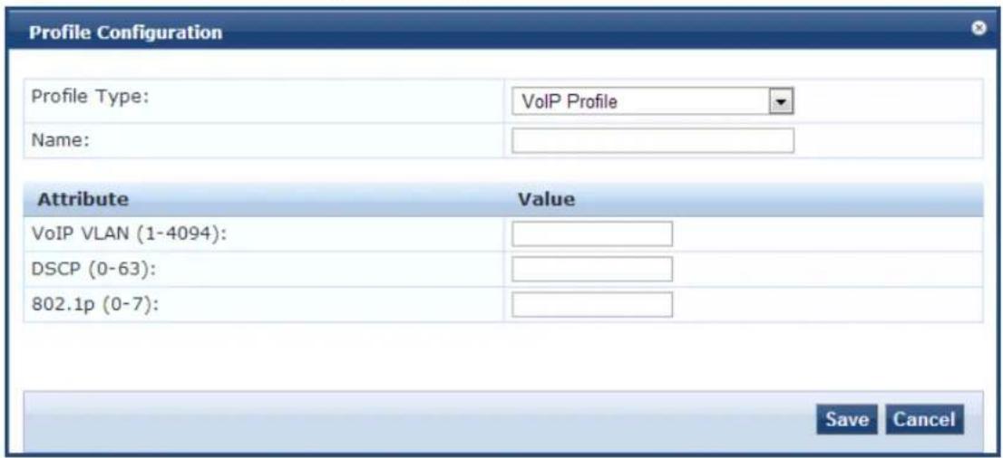
- Enter a name for the profile and configure the required attributes.
NetService Configuration
To define a NetService Configuration profile:
- Click the Manage NetServices link.
The NetService dialog opens:
Figure 369: NetService Configuration Profile
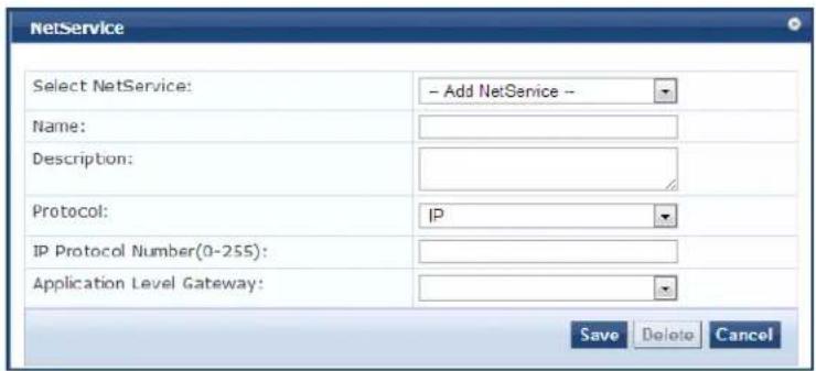
- Enter a name for the profile and configure the required attributes.
NetDestination Configuration
To define a NetDestination Configuration profile:
- Click the Manage NetDestinations link.
The NetDestinations dialog opens:
Figure 370: NetDestinations Configuration Profile
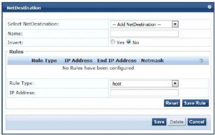
- Enter a name for the profile and configure the required attributes.
Time Range Configuration
To define a Time Range Configuration profile:
- Click the Manage Time Ranges link.
The Time Range Configuration dialog opens:
Figure 371: Time Range Configuration Profile
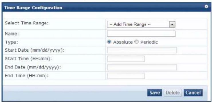
- Enter a name for the profile and configure the required attributes.
NAT Pool Configuration
To define a NAT (Network Address Translation) Pool Configuration profile:
- Click the Manage NAT Pool Configuration link.
The NAT Pool Configuration dialog opens:
Figure 372: NAT Pool Configuration Profile
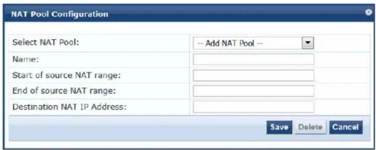
- Enter a name for the profile and configure the required attributes.
Adding a Stateless Access Control List
To add a Stateless Access Control List:
- Click the Add Stateless Access Control List link.
The Stateless Access Control List Configuration dialog opens:
Figure 373: Stateless Access Control List Configuration Profile
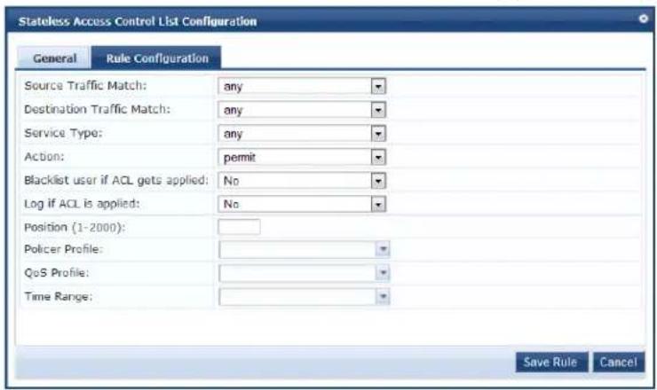
- Enter a name for the Stateless ACL.
- On the General tab, click the Add Rule link.
The Rule Configuration dialog opens.
- Enter the required attributes in the Rule Configuration dialog.
- Click Save Rule.
Adding a Session Access Control List
To add a Session Access Control List:
- Click the Add Session Access Control List link.
The Session Access Control List Configuration dialog opens.
- Enter a name for the Session ACL.
- On the General tab, click the Add Rule link.
The Rule Configuration dialog opens.
Figure 374: Session Access Control List Rule Configuration Profile
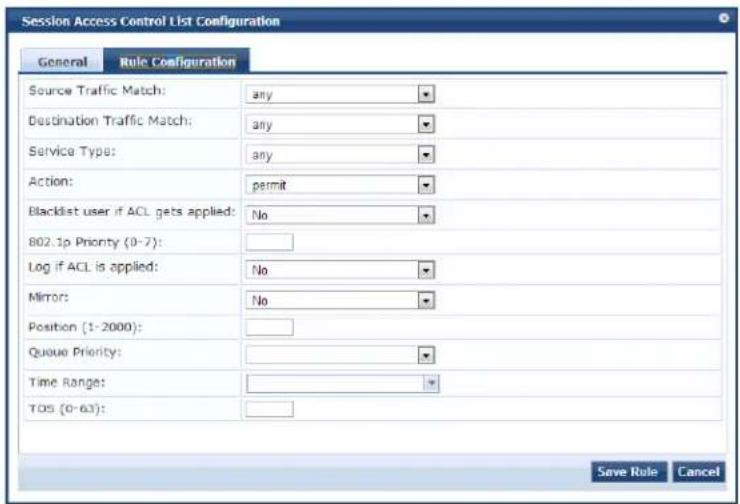
You can view different fields depending on the Action type you choose. For example, if you select the dual-nat action type, you can view the Dual NAT Pool field additionally to specify the action.
- Enter the required attributes in the Rule Configuration dialog.
- Click Save Rule.
Adding an Ethernet/MAC Access Control List
To add an Ethernet/MAC Access Control List:
- Click the Add Ethernet/MAC Access Control List link.
The Session Access Control List Configuration dialog opens.
The ACL Type is set to Ethertype.
Figure 375: Ethernet/MAC Access Control List Configuration Profile
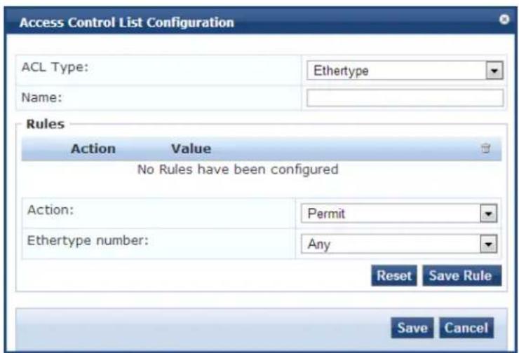
- Enter a name for the Ethernet/MAC Access Control List.
- Enter the required attributes in the Rules section of the page and click Reset, then click Save Rule.
- When finished, click Save.
Role Configuration Mode: Advanced
When you set Role Configuration Mode to Advanced, the Enforcement Profile page displays the Attributes tab (see Figure 376 below).
In Advanced mode, the Aruba Downloadable Role Enforcement profile provides two dictionaries and two attributes. The supported dictionaries and their associated attributes are:
• Dictionary: Aruba
Attribute: Aruba-CPPM-Role
The Aruba-CPPM-Role attribute supports Mobility Access Switches.
• Dictionary: Hewlett-Packard Enterprise
Attribute: HPE-CPPM-Role
The HPE-CPPM-Role attribute supports ArubaOS Switches.
You can use only one of the Advanced mode dictionaries at any given time; these dictionaries can't both be used at the same time.
To configure the Aruba Downloadable Role Enforcement > Advanced attributes:
- Navigate to Configuration > Enforcement > Profiles.
The Enforcement Profiles page opens in Standard Role Configuration Mode.
- Set the Role Configuration Mode to Advanced.
Figure 376: Downloadable Role Enforcement > Profile Tab (Advanced Mode)
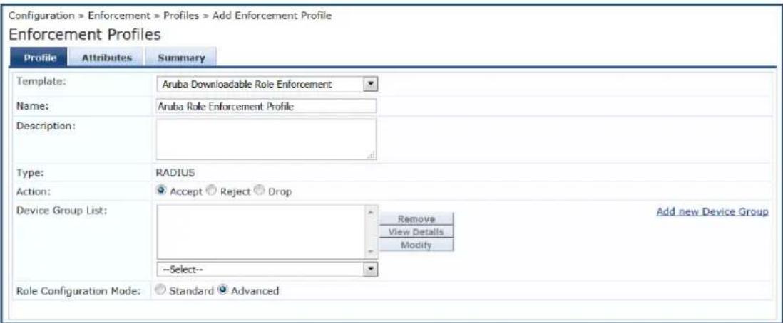
- Select the Attributes tab.
Figure 377: Configuring HPE-CPPM-Role Attribute
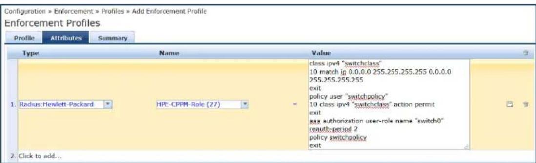
The Aruba > Aruba-CPPM-Role attribute is attribute is selected by default.

- To specify the Hewlett-Packard Enterprise dictionary and attribute:
a. Type: Hewlett-Packard Enterprise
b. Name: HPE-CPPM-Role (27)
c. Value: Enter the appropriate ArubaOS switch commands.
- Click Save.
Summary Information
For a profile in Standard Role Configuration Mode, the Summary tab summarizes the parameters configured in the Profile and Role Configuration tabs.
For a profile in Advanced Role Configuration Mode, the Summary tab summarizes the parameters configured in the Profile and Attribute tabs.
Dell RADIUS Enforcement Profile
This section describes the following Dell RADIUS Enforcement profile features:
• Profile Configuration on page 393
• Attributes Configuration on page 394
• Summary Information on page 395
Profile Configuration
Use the Profile tab to configure the template, type of the profile, and device group list. The following figure displays the Dell RADIUS Enforcement > Profile tab:
Figure 378: Dell RADIUS Enforcement > Profile Tab
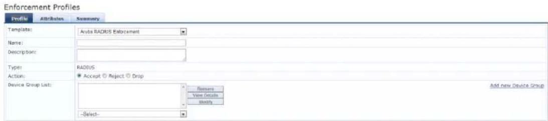
The following table describes the Dell RADIUS Enforcement > Profile tab parameters:
Table 197: Dell RADIUS Enforcement > Profile Parameters
| Parameter Action/Description | |
| Template Select | Dell RADIUS Enforcement. |
| Name | Enter the name of the profile.The name is displayed on theConfiguration>Enforcement>Profilespage. |
| Description | Enter a description that provides additional information about the profile. This description is displayed in on theConfiguration>Enforcement>Profilespage. |
| Type | This field is populated automatically. |
| Action | Click Accept, Reject, or Drop to define the action taken on the request. |
| Device Group List | Select a device group from the drop-down list. The list displays all configured device gro configured device groups are listed in theConfiguration > Network > Device Groupspage. After adding one or more device group(s), you can select a group and take one of the actions:To delete the selected Device Group List entry, click Remove.To see the device group parameters, clickView Details.To change the parameters of the selected device group, clickModify. |
| Add New Device Group | Click this link to add a new device group, For more information, seeAdding and Modify Device Groups on page 474. |
Attributes Configuration
Use the Attribute tab to configure the attribute type, name, and value for the enforcement profile. The following figure displays the Dell RADIUS Enforcement > Attributes tab:
Figure 379: Dell RADIUS Enforcement > Attributes Dialog
![Enforcement Profiles Profile Attributes Summary Type None Value 1. Radius: Aruba Aruba-User Role [1] = 2. Click to add...](/content/2026/05/842116/images/b4b7e361cd3b69c429d1a51a18918c7cf0346933a74833cadd420a657df2c6a8.jpg)
The following table describes the Dell RADIUS Enforcement > Attributes parameters:
Table 198: Dell RADIUS Enforcement > Attributes Parameters
| Attribute Action/Description | |
| Type Select one | of the following attribute types:Radius:DellRadius:IETFRadius:CiscoRadius: Hewlett-Packared-EnterpriseRadius: Lucent-Alcatel-EnterpriseRadius:MicrosoftRadius:AvendaFor more information, seeRADIUS Namespaces on page 928. |
| Name Select the | appropriateNameattribute.The options provided for theNameattribute depend on theTypeattribute selected. |
| Value | Specify the appropriateValueattribute.The options provided for theValueattribute depend on theTypeandNameattributes selected. |
Summary Information
The Summary tab summarizes the parameters configured in the Profile and Attributes tab.
Figure 380: Dell RADIUS Enforcement > Summary Tab
Enforcement Profiles
| Profile Attributes Summary | ||
| Profile: | ||
| Template: | Aruba RADIUS Enforcement | |
| Name: | RADIUS Enf | |
| Description: | System-defined profile to re-authenticate session (Aruba RADIUS Enf) | |
| Type: | RADIUS | |
| Action: | Accept | |
| Device Group List: | - | |
| Attributes: | ||
| Type Name Value | ||
| 1. Radius: Aruba Aruba-Admin-Role = %(Authorization:172.31.1.11:Groups) | ||
Cisco Downloadable ACL Enforcement Profile
Use this page to configure the Cisco Downloadable ACL Enforcement profile.
Profile Configuration
Use the Profile tab to configure the Cisco Downloadable ACL Enforcement profile.
The following figure displays the Cisco Downloadable ACL Enforcement > Profile dialog:
Figure 381: Cisco Downloadable ACL Enforcement > Profile Dialog
Enforcement Profiles

Specify the Cisco Downloadable ACL Enforcement > Profile parameters as described in the following table:
Table 199: Cisco Downloadable ACL Enforcement > Profile Parameters
| Parameter Action/Description | |
| Template Select | the Cisco Downloadable ACL Enforcement template. |
| Name Enter the | name of the profile.The name is displayed in the Name column on the Configuration > Enforcement > Profiles page. |
| Description Enter | a description of the profile.The description is displayed in the Description column on the Configuration > Enforcement > Profiles page. |
| Type The field is | populated automatically with Type: RADIUS. |
| Action | To define the action to take on the request, click Accept, Reject, or Drop. |
| Device Group List | Select a Device Group from the drop-down list. The list displays all configured device groups. All configured device groups are listed in theConfiguration > Network > Device Grouppage. After adding one or more device group(s), you can select a group and take one of following actions:To delete the selected Device Group List entry, click Remove.To see the device group parameters, clickView Details.To change the parameters of the selected device group, clickModify. |
| Add New Device Group | To add a new a device group, click theAdd New Device Grouplink. For more information, see Adding and Modifying Device Groups on page 474. |
Attributes Configuration
Use the Attribute tab to configure the attribute type, name, and value for the enforcement profile.
The following figure displays the Cisco Downloadable ACL Enforcement > Attributes dialog:
Figure 382: Cisco Downloadable ACL Enforcement > Attributes Dialog

Specify the Cisco Downloadable ACL Enforcement > Attributes parameters as described in the following table:
Table 200: Cisco Downloadable ACL Enforcement > Attributes Parameters
| Parameter Action/Description | |
| Type | Select one of the following attribute types:Radius:IETFRadius:Ciscoradius:Hewlett-Packared-EnterpriseRadius:Alcatel-Lucent-EnterpriseRadius:MicrosoftRadius:AvendaRadius:DellFor more information, see RADIUS Namespaces on page 928. |
| Name | The options displayed for the Name attribute depend on the Type attribute that was selected. |
| Value | The options displayed for the Value attribute depend on the Type and Name attributes that were selected. |
Summary Information
The Summary tab summarizes the parameters configured in the Cisco Downloadable ACL Enforcement profile.
Figure 383: Cisco Downloadable ACL Enforcement > Summary Tab
Enforcement Profiles
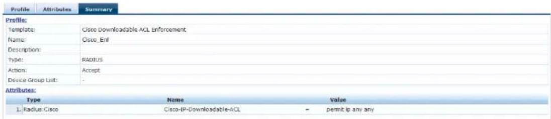
Cisco Web Authentication Enforcement Profile
Use this page to configure profile and attribute parameters for the Cisco Web Authentication Enforcement profile.
Profile Configuration
Use the Profile tab to configure the template, type of the profile, and device group list.
Figure 384: Cisco Web Authentication Enforcement > Profile Tab
Enforcement Profiles
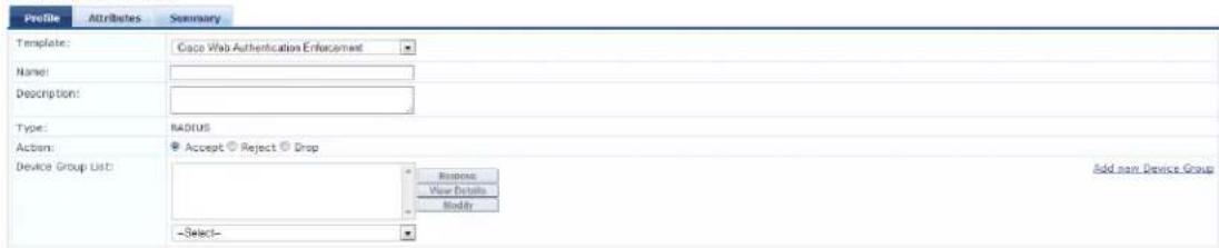
Specify the Cisco Web Authentication Enforcement > Profile tab parameters as described in the following table:
Table 201: Cisco Web Authentication Enforcement > Profile Tab Parameters
| Parameter Action/Description | |
| Template Select | the Cisco Web Authentication Enforcement template. |
| Name Enter the | name of the profile. |
| Description Enter | a description that provides additional information about the profile (recommended). |
| Type This field is populated automatically. | |
| Action | Click Accept, Reject, or Drop to define the action taken on the request. |
| Device Group List | Select a device group from the drop-down list. The list displays all configured device gro configured device groups are listed in theConfiguration > Network > Device Groupspage. After adding one or more device group(s), you can select a group and take one of the actions:To delete the selected Device Group List entry, click Remove.To see the device group parameters, clickView Details.To change the parameters of the selected device group, clickModify. |
| Add new Device Group | Click this link to add a new device group, For more information, seeAdding and Modify Device Groups on page 474. |
Attributes Configuration
Use the Attributes tab to configure the attribute name and attribute value. The following figure displays the Cisco Web Authentication Enforcement > Profile tab:
Figure 385: Cisco Web Authentication Enforcement > Attributes Tab
Enforcement Profiles
| Profile | Attributes | Summary | ||
| Type | Name | Value | T | |
| 1. | Radius-Cice | Cisco-AVPair | = | pvv-IV=15 |
| 2. | Radius-Cice | Cisco-AVPair | = | proxyad* 10-permit p any any |
| 3. | Click to add... | |||
The following table describes the Cisco Web Authentication Enforcement > Attributes parameters:
Table 202: Cisco Web Authentication Enforcement > Attributes Parameters
| Parameter Description | |
| Type | Select one of the following attribute types:Radius:ArubaRadius:IETFRadius:CiscoRadius: Hewlett-Packared-EnterpriseRadius: Lucent-Alcatel-EnterpriseRadius:MicrosoftRadius:AvendaFor more information, see RADIUS Namespaces on page 928. |
| Name | The options displayed for the Name attribute depend on the Type attribute that was selected. |
| Value | The options displayed for the Value attribute depend on the Type and Name attributes that were selected. |
Summary Information
The Summary tab summarizes the parameters configured in the Profile and Attribute tabs.
Figure 386: Cisco Web Authentication Enforcement > Summary Tab
Enforcement Profiles
| Profile Attributes Summary | |||
| Profile: | |||
| Templates: Cisco Web Authentication Enforcement | |||
| Name: Cisco_WebAuth_Enf | |||
| Description: | |||
| Type: RADIUS | |||
| Action: Accept | |||
| Device Group List: - | |||
| Attributes: | |||
| Type Name Value | |||
| 1. Radius:Cisco Cisco-AVPair = priv-IV=15 | |||
| 2. Radius:Cisco Cisco-AVPair = proxyacl# 10=permit ip any any |
W-ClearPass Entity Update Enforcement Profile
Use this page to configure profile and attribute parameters for the W-ClearPass Entity Update Enforcement profile.
Profile Configuration
Use the Profile tab to configure the template, type of the profile, and device group list.
Figure 387: W-ClearPass Entity Update Enforcement > Profile Tab
Enforcement Profiles
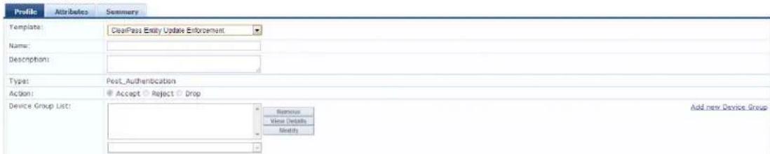
Specify the W-ClearPass Entity Update Enforcement > Profile parameters as described in the following table:
Table 203: W-ClearPass Entity Update Enforcement > Profile Parameters
| Parameter Acvtion/Description | |
| Template Select | the template from the drop-down list. In this context, select W-ClearPass Entity Update Enforcement. |
| Name | Enter the name of the profile. The name is displayed in the Name column on the Configuration > Enforcement > Profiles page. |
| Description Enter | a description that provides additional information about the profile. This description is displayed in the Description column on the Configuration > Enforcement > Profiles page. |
| Type This field is populated automatically. | |
| Action | Click Accept, Reject, or Drop to define the action taken on the request. |
| Device Group List | Select a device group from the drop-down list. The list displays all configured device gro configured device groups are listed in theConfiguration > Network > Device Groupspage. After adding one or more device group(s), you can select a group and take one of the actions:To delete the selected Device Group List entry, click Remove.To see the device group parameters, clickView Details.To change the parameters of the selected device group, clickModify. |
| Add new Device Group | Click this link to add a new device group, For more information, seeAdding and Modify Device Groups on page 474. |
Attributes Configuration
Use the Attribute tab to configure the attribute type, name, and value for the enforcement profile. The following figure displays the W-ClearPass Entity Update Enforcement > Attributes tab:
Figure 388: W-ClearPass Entity Update Enforcement Attributes tab

Specify the ClearPass Entity Update Enforcement > Attributes parameters as described in the following table:
Table 204: W-ClearPass Entity Update Enforcement > Attributes Parameters
| Attribute Description | |
| Type Select one | of the following attribute types:EndpointExpire-Time-UpdateGuestUserStatus-Update |
| Name | The options displayed for the Name attribute depend on the Type attribute that was selected. |
| Value | The options displayed for the Value attribute depend on the Type and Name attributes that were selected. |
Summary Information
The Summary tab summarizes the parameters configured in the Profile and Attributes tab.
Figure 389: W-ClearPass Entity Update Enforcement > Summary Tab
Enforcement Profiles
| Profile Attributes Summary | |||
| Profile: | |||
| Template: ClearPass Entity Update Enforcement | |||
| Name: Ent_update_Enf | |||
| Description: | |||
| Type: Post_Authentication | |||
| Action: Accept | |||
| Device Group List: - | |||
| Attributes: | |||
| Type Name Value | |||
| 1. Endpoint Enabled By = Admin | |||
| 2. Expire-Time-Update GuestUser = User1 | |||
| 3. GuestUser Location = Sunnyvale |
CLI-Based Enforcement Profile
Use this page to configure profile and attribute parameters for the CLI-Based Enforcement profile. The CLI-Based Enforcement profile contains the following tabs:
• Profile Configuration on page 401
• Attributes Configuration on page 402
• Summary Information on page 403
Profile Configuration
Use the Profile tab to configure the template, type of the profile, and device group list. The following figure displays the CLI-Based Enforcement > Profile tab:
Figure 390: CLI-Based Enforcement > Profile Tab
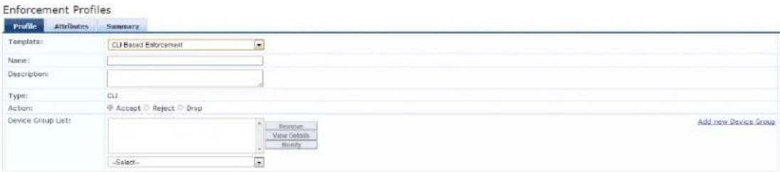
Specify the CLI-Based Enforcement > Profile tab parameters as described in the following table:
Table 205: CLI Based Enforcement > Profile Parameters
| Parameter Action/Description | |
| Template Select | the CLI Based Enforcement template. |
| Name Enter the | name of the profile. |
| Description Enter | a description that provides additional information about the profile. |
| Type This field is populated automatically. | |
| Action | Click Accept, Reject, or Drop to define the action taken on the request. |
| Device Group List | Select a device group from the drop-down list. The list displays all configured device groups. All configured device groups are listed in the Device Groups (Configuration > Network > Device Groups) page.After adding one or more device group(s), you can select a group and take one of the following actions:Click Remove to delete the selected Device Group List entry.Click View Details to see the device group parameters.Click Modify to change the parameters of the selected device group. |
| Add New Device Group | Click this link to add a new device group, For more information, see Adding and Modifying Device Groups on page 474. |
Attributes Configuration
Use the Attribute tab to configure the attribute type, name, and value for the enforcement profile.
Figure 391: CLI Based Enforcement > Attributes Tab

Specify the CLI Based Enforcement > Attributes parameters as described in the following table:
Table 206: CLI Based Enforcement > Attributes Parameters
| Attribute Action/Parameter | |
| Attribute Name | Select Command or Target Device. |
| Attribute Value | Specify the appropriate Attribute Value.The options provided for the Attribute Value depend on the selected Attribute Name. |
Summary Information
The Summary tab summarizes the parameters configured in the Profile and Attributes tab. The following figure displays the CLI-Based Enforcement > Summary tab:
Figure 392: CLI-Based Enforcement > Summary Tab
Enforcement Profiles
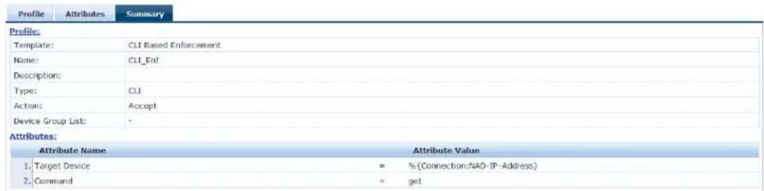
Filter ID Based Enforcement Profile
This section provides the following information:
• Profile Configuration on page 403
• Attributes Configuration on page 404
Use this page to configure profile and attribute parameters for the Filter ID based enforcement profile. 1 Filter ID Based Enforcement profile contains the following tabs:
Profile Configuration
The following figure displays the Filter ID Based Enforcement > Profile dialog:
Figure 393: Filter ID Based Enforcement Profile Dialog
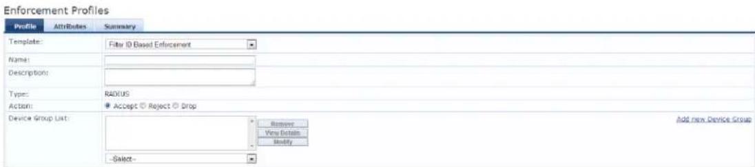
Specify the Filter ID Based Enforcement Profile parameters as described in the following table:
Table 207: Filter ID Based Enforcement > Profile Parameters
| Parameter Action/Description | |
| Template Select | the Filter ID Based Enforcement template. |
| Name | Enter the name of the profile. The name is displayed in the Name column on theConfiguration>Enforcement>Profilespage. |
| Description Enter | a description of the profile. The Description is displayed in the Description column on theConfiguration>Enforcement>Profilespage. |
| Type RADIUS. The field is populated automatically. | |
| Action | Enabled. Click Accept, Reject, or Drop to define the action taken on the request. |
| Device Group List | Select a Device Group from the drop-down list. The list displays all configured Device Group All configured device groups are listed in the Device Groups page: Configuration > Network > Device Groups. After you add one or more device group(s), you can select a group a one of the following actions:To delete the selected Device Group List entry, click Remove.To see the device group parameters, click View Details.To change the parameters of the selected device group, click Modify. |
| Add New Device Group | To add a new a device group, click the Add New Device Group link and see Adding and Modifying Device Groups on page 474. |
Attributes Configuration
The following figure displays the Filter ID Based Enforcement Profile > Attributes dialog:
Figure 394: Filter ID Based Enforcement Profile > Attributes Dialog

Specify the Filter ID Based Enforcement > Attributes parameters as described in the following table:
Table 208: Filter ID Based Enforcement Profile > Attributes Tab Parameters
| Parameter Description | |
| Type | Select one of the following attribute types:Radius:ArubaRadius:IETFRadius:Ciscoradius:Hewlett-Packared-EnterpriseRadius:Lucent-Alcatel-EnterpriseRadius:MicrosoftRadius:AvendaFor more information, seeRADIUS Namespaces on page 928. |
| Name | Select the desiredNameattribute.The options displayed for theNameattribute depend on the attribute that was selected |
| Value | Specify the appropriateValue.The options displayed for theValueattribute depend on theTypeattribute andNameattribute that were selected. |
Generic Application Enforcement Profile
Use this page to configure profile and attribute parameters for the Generic Application Enforcement profile. The Generic Application Enforcement profile contains the following tabs:
• Profile Configuration on page 405
• Attributes Configuration on page 406
• Summary Information on page 406
Profile Configuration
Use the Profile tab to configure the template, type of the profile, and device group list. The following figure displays the Generic Application Enforcement > Profile tab:
Figure 395: Generic Application Enforcement > Profile Tab
Enforcement Profiles
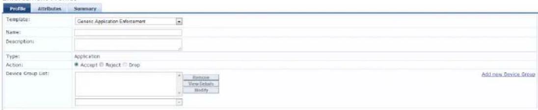
Specify the Generic Application Enforcement > Profile parameters as described in the following table:
Table 209: Generic Application Enforcement > Profile Tab Parameters
| Parameter Action/Description | |
| Template | Select the template from the drop-down list. In this context, select Generic Application Enforcement. |
| Name | Enter the name of the profile. The name is displayed in the Name column on the Configuration > Enforcement > Profiles page. |
| Description | Enter a description that provides additional information about the profile. This description is displayed in the Description column on the Configuration > Enforcement > Profiles page. |
| Type This field is populated automatically. | |
| Action | Click Accept, Reject, or Drop to define the action taken on the request. |
| Device Group List | Select a device group from the drop-down list. The list displays all configured device groups. All configured device groups are listed in the Device Groups (Configuration > Network > Device Groups) page.After adding one or more device group(s), you can select a group and take one of the following actions:To delete the selected Device Group List entry, click Remove.To see the device group parameters, click View Details.To change the parameters of the selected device group, click Modify. |
| Add New Device Group | Click this link to add a new device group, For more information, see Adding and Modifying Device Groups on page 474. |
Attributes Configuration
Use the Attribute tab to configure the attribute type, name, and value for the enforcement profile. The following figure displays the Generic Application Enforcement > Attributes tab:
Figure 396: Generic Application Enforcement > Attributes Tab

Specify the Generic Application Enforcement > Attributes parameters as described in the following table:
Table 210: Generic Application Enforcement > Attributes Parameters
| Parameter Action/Description | |
| Attribute Name | Select an attribute name from the drop-down list. The list has multiple names. |
| Attribute Value | Displays the options for the Attribute Value depend on the selected Attribute Name. |
Summary Information
The Summary tab summarizes the parameters configured in the Profile and Attributes tab.
Figure 397: Generic Application Enforcement > Summary Tab
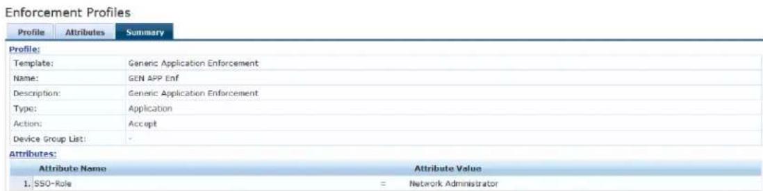
HTTP Based Enforcement Profile
Use this page to configure the HTTP based Enforcement Profile.
Profile Configuration
The following figure displays the HTTP Based Enforcement > Profile dialog:
Figure 398: HTTP Based Enforcement Profile Dialog
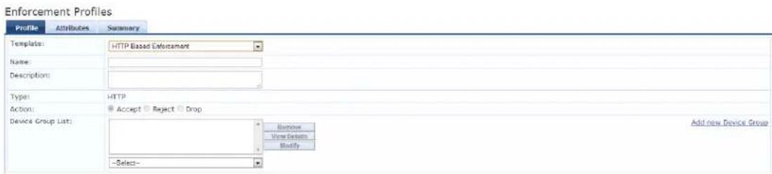
Specify the HTTP Based Enforcement > Profile parameters as described in the following table:
Table 211: HTTP Based Enforcement Profile Parameters
| Parameter Action/Description | |
| Template Select | the HTTP Based Enforcement template. |
| Name Enter the | name of the profile.The name is displayed in the Name column on the Configuration > Enforcement > Profiles page. |
| Description Enter | a description of the profile.The description is displayed in the Description column on the Configuration > Enforcement > Profiles page. |
| Type This field is populated automatically with HTTP. | |
| Action Disabled. | |
| Device Group List | Select a Device Group from the drop-down list.The list displays all configured Device Groups. All configured device groups are listed in the Configuration > Network > Device Groups.page. After you add one or more device group(s), you can select a group and take one of the following actions:To delete the selected Device Group List entry, click Remove.To see the device group parameters, click View Details.To change the parameters of the selected device group, click Modify. |
| Add New Device Group | To add a new a device group, click the Add New Device Group link and see Adding and Modifying Device Groups on page 474. |
Attributes Configuration
Figure 399: HTTP Based Enforcement Attributes Dialog
Enforcement Profiles
| Profile | Attributes | Summary |
| Attribute Name | Attribute Value | |
| 1. | Target Server | = Select server |
| 2. | Action | = Select action |
| 3. | Click to add... | |
Table 212: HTTP Based Enforcement Attributes Parameters
| Parameter Action/Description | |
| Attribute Name | Select the attribute name: Target Server or Action. |
| Attribute Value | Specify the appropriate value.The options displayed for the Attribute Value depend on the Attribute Name that was selected. |
RADIUS Based Enforcement Profile
Use this page to configure profile and attribute parameters for the RADIUS based enforcement profiles.
Profile Configuration
The following figure displays the RADIUS Based Enforcement Profile tab:
Figure 400: RADIUS Based Enforcement > Profile Tab
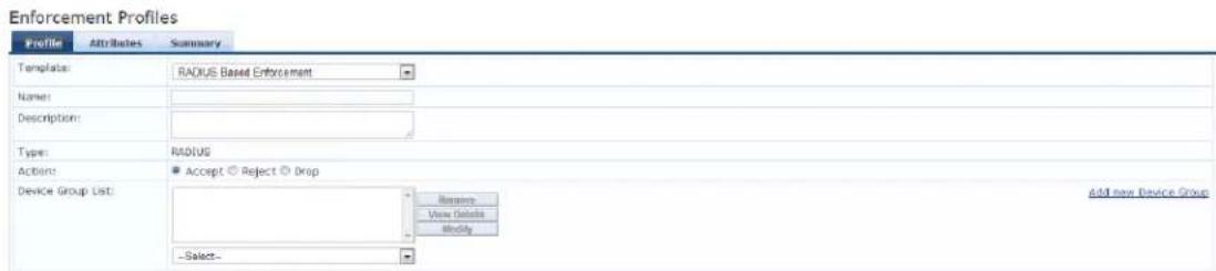
Specify the RADIUS Based Enforcement Profile parameters as described in the following table:
Table 213: RADIUS Based Enforcement Profile Parameters
| Parameter Action/Description | |
| Template Select | the RADIUS Based Enforcement template. |
| Name Enter the | name of the profile. |
| Description Enter | a description of the profile. |
| Type RADIUS. | This field is populated automatically. |
| Action | Enabled. Click Accept, Reject, or Drop. |
| Device Group List | Select a Device Group from the drop-down list.All configured device groups are listed in theConfiguration > Network > Device Groups page. After you add one or more device group(s), you can select a group and take one of the following actions:To delete the selected Device Group List entry, clickRemove.To see the device group parameters, clickView Details.To change the parameters of the selected device group, clickModify. |
| Add New Device Group | To add a new a device group, click theAdd New Device Grouplink and see Adding and Modifying Device Groups on page 474 |
Attributes Tab
The following figure displays the RADIUS Based Enforcement > Attributes dialog:
Figure 401: RADIUS Based Enforcement Attributes Dialog

Specify the RADIUS Based Enforcement > Attributes parameters as described in the following table:
Table 214: RADIUS Based Enforcement > Attributes Parameters
| Parameter Description | |
| Type Select one | of the following attribute types:Radius:ArubaRadius:IETFRadius:Ciscoradius: Hewlett-Packared-EnterpriseRadius: Lucent-Alcatel-EnterpriseRadius:MicrosoftRadius:AvendaFor more information, seeRADIUS Namespaces on page 928. |
| Name | The options displayed for theNameattribute depend on theTypeattribute that was selected. |
| Value | The options displayed for theValueattribute depend on theTypeandNameattributes that were selected. |
RADIUS Change of Authorization (CoA) Profile
Use this page to configure the RADIUS Change of Authorization (CoA) enforcement profile.
Profile Configuration
The following figure displays the RADIUS Change of Authorization (CoA) > Profile tab:
Figure 402: RADIUS Change of Authorization (CoA) > Profile Tab
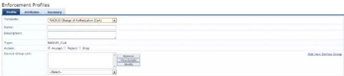
Specify the RADIUS Change of Authorization (CoA) > Profile tab parameters as described in the following table:
Table 215: RADIUS Change of Authorization (CoA) Profile Parameters
| Parameter | Action/Description |
| Template | Select the RADIUS Change of Authorization (CoA) template. |
| Name | Enter the name of this enforcement profile. |
| Type | RADIUS_CoA is automatically populated. |
| Parameter Action/Description | |
| Action Disabled. | |
| Device Group List | Optionally, select a Device Group from the drop-down list.All configured device groups are listed on theDevice Groupspage:Configuration >Network>Device Groups. After you add one or more device group(s), you can select a group a one of the following actions:To delete the selected Device Group List entry, clickRemove.To see the device group parameters, clickView Details.To change the parameters of the selected device group, clickModify. |
| Add New Device Group | To add a new a device group, click theAdd New Device Grouplink and seeAdding and Modifying Device Groups on page 474. |
Attributes Configuration
The following figure displays the RADIUS Change of Authorization (CoA) > Attributes tab:
Figure 403: RADIUS Change of Authorization (CoA) > Attributes Dialog

The following table describes the RADIUS Change of Authorization (CoA) > Attributes parameters:
Table 216: RADIUS Change of Authorization (CoA) Attributes Parameters
| Parameter Action/Description | |
| Select RADIUS CoA Template | Select one of the following RADIUS CoA templates:• Dell - Change-User-Role• Aruba - Change-VPN-User-Role• Cisco - Bounce-Host-Port• Cisco-Disable-Host-Port• Cisco - Reauthenticate-Session• Hewlett-Packard-Enterprise - Change-VLAN• Hewlett-Packard-Enterprise - Generic-CoA• Hewlett-Packard-Enterprise - Port-Bounce-Host-HP• IETF- Generic-CoA-IETF• IETF - Terminate-Session-IETF |
| Type | Select one of the following attribute types:■ Radius:IETF■ Radius:Cisco■ Radius: Hewlett-Packared-Enterprise■ Radius: Alcatel-Lucent-Enterprise■ Radius:Microsoft■ Radius:Avenda■ Radius:Dell |
| Name | The options displayed for the Name attribute depend on the Template and Type attributes that were selected. |
| Value | The content for the Value attribute depends on the Template, Type, and Name attributes that were selected. |
Session Notification Enforcement Profile
Use this page to configure the Session Notification Enforcement profile.
You can send notification of a change in IP address to any external context server (such as a firewall) b configuring that server as a generic HTTP server and adding the appropriate generic HTTP context server actions.
The content of the payload to be posted by Policy Manager to the external server is based on the REST defined by the external server.
Profile Configuration
The following figure displays the Session Notification Enforcement > Profile tab:
Figure 404: Session Notification Enforcement > Profile Configuration Dialog
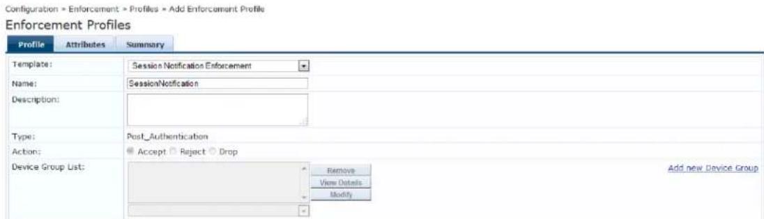
The following table describes the Session Notification Enforcement > Profile parameters:
Table 217: Session Notification Enforcement Profile Tab Parameters
| Parameter Action/Description | |
| Template Select | Session Notification Enforcement. |
| Name Enter the | name of the profile. |
| Description Enter | a description of the profile (recommended). |
| Type The field is | populated automatically with: Post_Authentication. |
| Action Disabled. | |
| Device Group List | Select a device group from the drop-down list.All configured device groups are listed in the Device Groups Configuration > Network Device Groups page. |
| Add New Device Group | To add a new a device group, click the Add New Device Group link. See Adding and Modifying Device Groups on page 474for more information. |
Attributes Configuration
The following figure displays the Session Notification Enforcement > Attributes dialog:
Figure 405: Session Notification Enforcement > Attributes Configuration Dialog

Specify the Session Notification Enforcement > Attributes parameters as described in the following table:
Table 218: Session Notification Enforcement > Attributes Parameters
| Parameter Action/Description | |
| Type | Select one of the following Type attributes:Session-CheckSession-NotifyPalo Alto integration is extended to Guest MAC Caching use cases. Configure the Session-Check attributes as follows:Session-Check::Username = %{Endpoint:Username}NOTE: Post authentication sends the Guest username instead of the MAC address in the user ID updates.Session-Notify: The Name options are:Login ActionLogout ActionServer IPServer TypeServer Type options: Generic HTTP Palo Alto Networks Panorama Palo Alto Networks FirewallServer IP options: a choice of IP address/hostnames for the corresponding type of server as Value. The Target Server attribute must be specified before you can use the Server IP option.Once the server IP address is selected, you can select Login Action or Logout Action. The list of actions defined for the selected server will be shown as available choices for Value.This enforcement type should be used both for Palo Alto devices and any Generic HTTP servers |
| Name | The options displayed for the Name attribute depend on the Type attribute that was selected. |
| Value | The options displayed for the Value attribute depend on the Type and Name attributes that were selected. |
Summary Information
This Summary tab summarizes the parameters configured for Session Notification Enforcement.
Figure 406: Session Notification Enforcement > Summary Tab
Enforcement Profiles
| Profile Attributes Summary | ||
| Profile: | ||
| Template: | Session Notification Enforcement | |
| Name: | SessionNotification | |
| Description: | ||
| Type: | Post_Authentication | |
| Action: | Accept | |
| Device Group List: | - | |
| Attributes: | ||
| Type | Name | Value |
| 1. Session-Check | Username = admin | |
| 2. Session-Notify | Logout Action = | |
Session Restrictions Enforcement Profile
W-ClearPass uses Keep-Alive messages to issue CoA (Change of Authorization) for a Session Restrictions Enforcement Profile if OnGuard Agent is disconnected (see below, Examples of Session-Check Enforcement
Profile Configurations). For related information, see OnGuard Global Agent Settings on page 708.
Profile Configuration
To configure Profile and Attribute parameters for a Session Restrictions Enforcement profile:
- Navigate to Configuration > Enforcement > Profiles.
The Enforcement Profiles page opens.
- Click Add.
The Add Enforcement Profiles > Profile tab opens.
- From the Template drop-down, select Session Restrictions Enforcement.
The Add Session Restrictions Enforcement > Profile dialog opens:
Figure 407: Add Session Restrictions Enforcement > Profile Tab
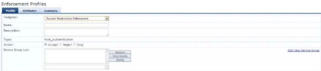
- Specify the Session Restrictions Enforcement > Profile parameters as described in the following table:
Table 219: Session Restrictions Enforcement Profile Parameters
| Parameter Action/Description | |
| Template Select | Session Restrictions Enforcement. |
| Name Enter the | name of the enforcement profile. |
| Description Optionally, enter a description of the enforcement profile (recommended). | |
| Type Post_Authentication.The Type field is populated automatically when you select the Session Restrictions Enforcement template. | |
| Action | By default, this field is disabled. It is enabled only when RADIUS type is selected. |
| Device Group List | Select a device group from the drop-down list. The list displays all configured device group All configured device groups are listed in the Configuration > Network > Device Group page. After you add one or more device groups, select a group and take one of the fo actions:To delete the selected device group list entry, click Remove.To see the device group parameters, click View Details.To change the parameters of the selected device group, click Modify. |
| Add New Device Group | To add a new a device group, click the Add New Device Group link. For more information, see Adding and Modifying Device Groups on page 474. |
Attributes Configuration
The following figure displays the Session Restrictions Enforcement > Attributes tab:
Figure 408: Session Restrictions Enforcement Profile > Attributes Dialog

- Specify the Session Restrictions Enforcement > Attributes parameters as described in Table 220:
Table 220: Session Restrictions Enforcement Attributes Parameters
| Parameter Description | |
| Type Select from | the following attribute types:Bandwidth-CheckExpiry-CheckPost-Auth-CheckSession-Check |
| Name | The options displayed for the Name attribute depend on the Type attribute that was selected.Type: Bandwidth-CheckAllowed-Limit: Defines the total bandwidth limit to be allowed per user or endpoint.Check-Type: Defines the period/interval for bandwidth-based checks. Applicable only with Allowed-Limit.Limit-Units: Defines the metric for bandwidth-based checks (KB, MB, GB, TB). Applicable only with Allowed-Limit.Start-Date: Defines the start date for bandwidth-based checks. Applicable only with Allowed-Limit.Start-Time: Defines the start time for bandwidth-based checks. Applicable only with Allowed-Limit.Stop-Date: Defines the stop date for bandwidth-based checks. Applicable only with Allowed-Limit.Stop-Time: Defines the stop time for bandwidth-based checks. Applicable only with Allowed-Limit.For configuration examples, see the next section, Examples of Bandwidth-Check Enforcement Profile Configurations.Type: Expiry-CheckExpiry-ActionType: Post-Auth-CheckActionType: Session-CheckActive-Session-Count: Defines the number of active sessions to be allowed per user or endpoint.Agent-Connection: Set the value to Down to have W-ClearPass check to see if the OnGuard Agent is down.Allowed-Duration: Defines the total session duration to be allowed per user or endpoint.Check-Type: Defines the period or interval for duration-based checks. Applicable only with Allowed-Duration.Duration-Units: Defines the metric for duration-based checks. Applicable only with Allowed-Duration.Start-Date: Defines the start date for duration-based checks. Applicable only with Allowed-Duration.Start-Time: Defines the start time for duration-based checks. Applicable only with Allowed-Duration.Stop-Date: Defines the stop date for duration-based checks. Applicable only with Allowed-Duration.Stop-Time: Defines the stop time for duration-based checks. Applicable only with Allowed Duration.■Username:Defines the username for which session restrictions are enabled. Used when the client MAC address is to be defined as a username.For configuration examples, see the section below,Examples of Session-Ch Enforcement Profile Configurations. |
| Value | The options displayed for theValueattribute depend on theTypeand Nameattributes that were selected. |
Examples of Bandwidth-Check Enforcement Profile Configurations
The following are typical examples of Session Restriction > Bandwidth-Check enforcement profile configurations:
- Allowed-Limit: Users/Endpoints will be disconnected after exceeding the 50 MB daily limit:
■ Bandwidth-Check > Allowed-Limit = 50
■ Bandwidth-Check > Limit-Units = MB
■ Bandwidth-Check > Check-Type = Daily
■ Post-Auth-Check > Action = Disconnect
- Allowed-Limit: Users/Endpoints will be disconnected after exceeding 1 GB total bandwidth consumption.
Also, users are allowed access to the network only during the defined period (between 9:00 a.m. and p.m.).
■ Bandwidth-Check > Allowed-Limit = 1
■ Bandwidth-Check > Limit-Units = GB
■ Bandwidth-Check > Check-Type = Total
■ Bandwidth-Check > Start-Time = 09:00:00
■ Bandwidth-Check > Stop-Time = 18:00:00
■ Post-Auth-Check > Action = Disconnect
Examples of Session-Check Enforcement Profile Configurations
The following are typical examples of Session Restriction > Session-Check enforcement profile configurations:
- Active Session Count: The Users/Endpoints active session count is set to 5. Users/Endpoints connecting after the session count reaches 5 are disconnected:
■ Session-Check > Active-Session-Count = 5
■ Post-Auth-Check > Action = Disconnect
- Agent-Connection: You can disconnect a session if OnGuard Agent is down:
■ Session-Check > Agent-Connection = Down
■ Post-Auth-Check > Action = Disconnect
- Session Duration: The User/Endpoint is allowed access for 60 minutes daily. Users/Endpoints that exceed this session duration limit are disconnected:
■ Session-Check > Allowed-Duration = 60
■ Session-Check > Duration-Units = Minutes
■ Session-Check > Check-Type = Daily
■ Post-Auth-Check > Action = Disconnect
- Session Duration: The User/Endpoint is allowed access to the network daily for three hours in a specified time period (between 9:00 a.m. and 5:00 p.m.)
■ Session-Check > Allowed-Duration = 3
■ Session-Check >Duration-Units = Hours
■ Session-Check > Check-Type = Daily
■ Session-Check > Start-Time = 09:00:00
■ Session-Check Stop-Time = 17:00:00
■ Post-Auth-Check > Action = Disconnect
SNMP-Based Enforcement Profile
Use this page to configure the SNMP-Based Enforcement profile.
Profile Configuration
The following figure displays the SNMP Based Enforcement > Profile dialog:
Figure 409: SNMP Based Enforcement > Profile Dialog
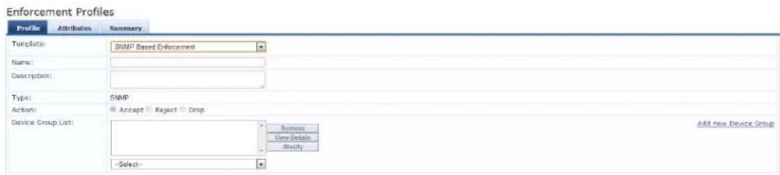
Specify the SNMP Based Enforcement > Profile parameters as described in the following table:
Table 221: SNMP Based Enforcement > Profile Tab Parameters
| Parameter Description | |
| Template Select | the SNMP Based Enforcement template. |
| Name Enter the | name of the profile.The name is displayed in the Name column on the Configuration > Enforcement > Profiles page. |
| Description Enter | a description of the profile (recommended).The description is displayed in the Description column on the Configuration > Enforcement > Profiles page. |
| Type | SNMP. The field is populated automatically. |
| Action Disabled. | |
| Device Group List | Select a Device Group from the drop-down list.All configured device groups are listed in theConfiguration > Network > Device Grouppage. After you add one or more device group(s), you can select a group and take one following actions:To delete the selected Device Group List entry, clickRemove.To see the device group parameters, clickView Details.To change the parameters of the selected device group, clickModify. |
| Add New Device Group | To add a new a device group, click theAdd New Device Grouplink. See Adding and Modifying Device Groups on page 474. |
Attributes Configuration
The following figure displays the SNMP Based Enforcement > Attributes dialog:
Figure 410: SNMP Based Enforcement > Attributes Dialog

Specify the SNMP Based Enforcement > Attributes parameters as described in the following table:
Table 222: SNMP Based Enforcement Attributes Parameters
| Parameter Action/Description | |
| Attribute Name | Select from:VLAN IDSession Timeout (in seconds)Reset Connection (after the settings are applied) |
| Attribute Value | The options displayed for the Attribute Value depends on the Attribute Name that was selected. |
TACACS+ Based Enforcement Profile
Use this page to configure the TACACS+ Based Enforcement profile.
Profile Configuration
The following figure displays the TACACS+ Based Enforcement > Profile tab:
Figure 411: TACACS+ Based Enforcement Profile Dialog
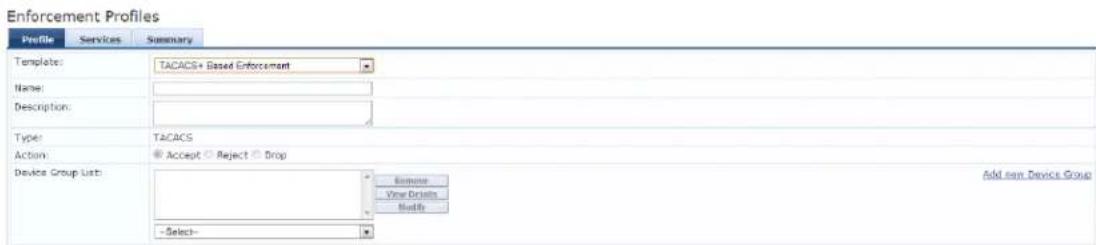
Specify the TACACS+ Based Enforcement Profile > Profile parameters as described in the following table:
Table 223: TACACS+ Based Enforcement > Profile Parameters
| Parameter Action/Description | |
| Template Select | the TACACS+ Based Enforcement template. |
| Name Enter the | name of the profile.The name is displayed in the Name column on the Configuration > Enforcement > Profiles page. |
| Description Enter | a description of the profile (recommended).The description is displayed in the Description column on the Configuration > Enforcement > Profiles page. |
| Type TACACS. | The field is populated automatically. |
| Action Disabled. | |
| Device Group List | Select a Device Group from the drop-down list.All configured device groups are listed in the Configuration > Network > Device Group page. After you add one or more device group(s), you can select a group and take one following actions:To delete the selected Device Group List entry, click Remove.To see the device group parameters, click View Details.To change the parameters of the selected device group, click Modify. |
| Add New Device Group | To add a new a device group, click the Add New Device Group link. See Adding and Modifying Device Groups on page 474. |
Services Configuration
The following figure displays the TACACS+ Based Enforcement > Services dialog:
Figure 412: TACACS+ Based Enforcement > Services Dialog
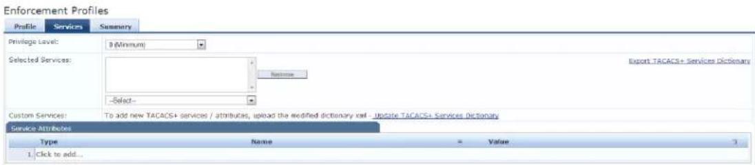
Specify the TACACS+ Based Enforcement Profile > Service parameters as described in the following table:
Table 224: TACACS+ Based Enforcement > Services Parameters
| Parameter Action/Description | |
| Privilege Level | Select a level between 0 and 15, with 0 being the minimum privilege level and 15 being the highest. |
| Selected Services Select one or more of the following services:ShellPIX ShellPPP:IPPPP:IPXPPP:LCPARAPcpass:HTTPWireless-WCS:HTTPCiscoWLC:CommonDell:CommonAMP:httpsNCS:HHHP | |
| Export All TACACS+ Services Dictionaries | Click this link to download the TACACS+ Services dictionary to the local computer. |
| Authorize Attribute Status Select one of the following options:ADDREPLACE | |
| Custom Services To add new TACACS+ services / attributes or upload the modified XML dictionary, click the Update TACACS+ Services Dictionary link. | |
| Service Attributes | |
| Type Select one of the following Service Attribute types:PPP:IPShellcpass:HTTP | |
| Name | The options displayed for the Name attribute depend on the Type attribute that was selected. |
| Value | The options displayed for the Value attribute depend on the Type and Name attributes that were selected. |
VLAN Enforcement Profile
Use this page to configure the VLAN Enforcement profile.
Profile Configuration
The following figure displays the VLAN Enforcement > Profile configuration dialog:
Figure 413: VLAN Enforcement > Profile Configuration Dialog
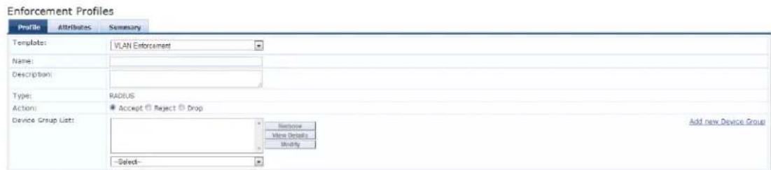
Specify the VLAN Enforcement > Profile parameters as described in the following table:
Table 225: VLAN Enforcement > Profile Parameters
| Parameter Description | |
| Template | Select the template from the drop-down list. In this context, select VLAN Enforcement. |
| Name | Enter the name of the profile. |
| Description | Enter a description of the profile. |
| Type | RADIUS. The field is populated automatically. |
| Action | To define the action taken on the request, click Accept, Reject, or Drop. |
| Device Group List | Select a Device Group from the drop-down list.All configured device groups are listed in theConfiguration > Network > Device Group page. After you add one or more device group(s), you can select a group and take one following actions:To delete the selected Device Group List entry, click Remove.To see the device group parameters, clickView Details.To change the parameters of the selected device group, clickModify. |
| Add New Device Group | To add a new a device group, click theAdd New Device Grouplink and seeAdding and Modifying Device Groups on page 474. |
Attributes Configuration
The following figure displays the VLAN Enforcement > Attributes dialog:
Figure 414: VLAN Enforcement Attributes Dialog

Specify the RADIUS Based Enforcement > Attributes parameters as described in the following table:
Table 226: VLAN Enforcement Attributes Tab Parameters
| Parameter Description | |
| Type | Select one of the following attribute types:Radius:ArubaRadius:IETFRadius:CiscoRadius: Hewlett-Packared-EnterpriseRadius: Alcatel-Lucent-EnterpriseRadius:MicrosoftRadius:AvendaFor more information, seeRADIUS Namespaces on page 928 |
| Name | The options displayed for theNameattribute depend on theTypeattribute that was selected. |
| Value | The options displayed for theValueattribute depend on theTypeandNameattributes that were selected. |
This chapter describes the following types of simulations:
• Active Directory Authentication Simulation
• Application Authentication Simulation
• Audit Simulation
• Chained Simulation
• Enforcement Policy Simulation
• RADIUS Authentication Simulation
• Role Mapping Simulation
• Service Categorization Simulation
After creating the policies, use the Policy Simulation utility in the Configuration > Policy Simulation page to evaluate those policies before deployment.
The Policy Simulation utility applies a set of request parameters as input against a given policy component and displays the outcome.
The following figure displays the Policy Simulation page:
Figure 415: Policy Simulation Page

The following table describes the Policy Simulation page parameters:
Table 227: Policy Simulation Configuration Parameters
| Parameter Description | |
| Name | Displays the name of the name of the policy simulation. |
| Type | Displays the type of the policy simulation. |
| Description | Displays additional information about the policy simulation. |
Active Directory Authentication Simulation
This section provides the following information:
- Adding an Active Directory Simulation
• Viewing the Simulation Results
This simulation tests authentication against an Active Directory domain or trusted domain to verify that t W-ClearPass Policy Manager domain membership is valid.

The Attributes tab is not available for this simulation type.
Adding an Active Directory Simulation
To add the RADIUS authentication server for the authentication test:
- Navigate to the Configuration > Policy Simulation > Add page. The Add Policy Simulation dialog appears.
- Enter the Name of the simulation.
- From the Type drop-down list, select Active Directory Authentication. The following figure displays the Active Directory Authentication Simulation dialog.
Figure 416: Active Directory Authentication - Simulation Tab
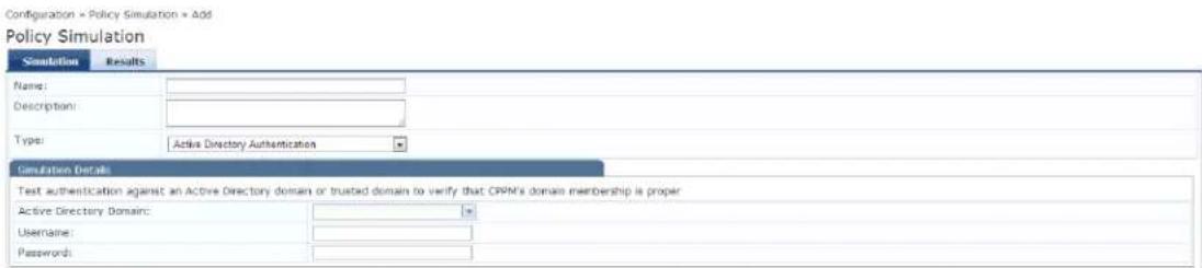
The following table describes the Active Directory Authentication - Simulation tab parameters:
Table 228: Active Directory Authentication Simulation Tab Parameters
| Parameter Description | |
| Active Directory Domain Select the domain(s) to which the node is joined. | |
| Username | Enter the username to login to the domain. |
| Password | Enter the password to login to the domain. |
Viewing the Simulation Results
The Results tab for the Active Directory Authentication simulation displays a summary of the Authentication test and provides a status message.
The following figure displays the Active Directory Authentication - Results tab:
Figure 417: Active Directory Authentication Results Tab
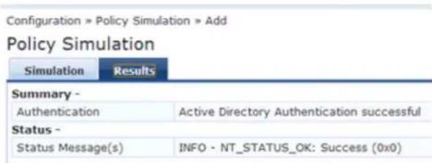
Table 229: Active Directory Authentication Results Tab Parameters
| Parameter Description | |
| Summary Displays the results of the Active Directory Authentication simulation. | |
| Status Displays the status message. |
Application Authentication Simulation
This simulation tests authentication requests generated from W-ClearPass Guest. The following figure disp the Application Authentication policy simulation settings available on the Configuration > Policy Simulation > Add page:
Simulation Tab
Figure 418: Application Authentication - Simulation Tab

Table 230: Application Authentication Simulation Tab Parameters
| Parameter Description | |
| CPPM IP Address/FQDN Enter the IP Address or FQDN of the domain(s) to which the node is joined. | |
| Username | Enter the username. |
| Password | Enter the password. |
Attributes Tab
Enter the attributes of the policy component to be tested. The following figure displays the Application Authentication - Attributes tab:
Figure 419: Application Authentication - Attributes Tab
| Simulation | Attributes | Results | |||
| Type | Name | Value | 3 | ||
| 1 | Application | Name | = Enter App Name | 80 9 | |
| 2 | Click to add... | ||||
Table 231: Application Authentication - Attributes Tab Parameters
| Attribute Parameter | |
| Type Select Application or select Application:ClearPass. See Application Namespace on page 920 | |
| Name | The options displayed for the Name Attribute depend on the Type Attribute that was selected. |
| Value | The options displayed for the Value Attribute depend on the Type Attribute and Nam Attribute that were selected. |
Results tab
The Results tab of the Application Authentication simulation displays the outcome of the Authentication Result and the Application Authentication Output Attributes. The following figure displays the Application Authentication Results tab:
Figure 420: Application Authentication Results Tab
Configuration » Policy Simulation » Edit - APP
Policy Simulation - APP
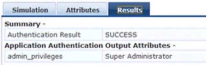
Table 232: Application Authentication Results Tab Parameters
| Parameter Description | |
| Summary Displays the results | of the Active Directory Authentication simulation. |
| Application Authentication Output Attributes | Displays the output attributes, such as Super Administrator. |
Audit Simulation
This simulation allows you to specify an audit against a Nessus Server or Nmap Server with its IP addre. The Attributes tab is not available for this simulation type.

Audit simulations can take more than 30 minutes. An AuditinProgress status message is displayed until the audit is completed.
The following figure displays the Audit Simulation tab:
Figure 421: Audit Simulation - Simulation Tab

The following table describes the Audit Simulation - Simulation tab parameters:
Table 233: Audit Simulation Tab Parameters
| Parameter Description | |
| Audit Server Select [Nessus Server] or [Nmap Audit]. | |
| Audit Host IP Address | Enter the host IP address of the audit host. |
Results Tab
The following figure displays the Audit Simulation - Results tab:
Figure 422: Audit Simulation Results Tab
Configuration » Policy Simulation » Edit - audit
Policy Simulation - audit
| Simulation | Results |
| Summary - | |
| Audit Status | AuditInProgress |
| Temporary Status | TRANSITION (15) |
| Audit Timeout | 60 seconds |
| Audit Output Attributes - | |
| Avenda:Audit:Audit-Status | AUDIT_INPROGRESS |
The following table describes the Audit Simulation - Results tab parameters:
Table 234: Audit Results Tab Parameters
| Parameter Description | |
| Summary Displays information about the Audit Status, Temporary Status, and Audit Timeout. | |
| Audit Output Attributes | Displays the Audit-Status such as AUDIT_INPROGRESS. |
Chained Simulation
Given the service name, authentication source, user name, and an optional date and time, the chained simulation combines the results of role mapping, posture validation and enforcement policy simulations a displays the corresponding results.
Simulation Tab
The following figure displays the Chained Simulation Simulation tab:
Figure 423: Chained Simulation Tab
![Policy Simulation Simulation Attributes Results Name: Description: Type: Charmed Simulation Simulation Details Test end-to-end policy evaluation that includes Role-Mapping and Enforcement policies given a Service and input details Service: [Policy Manager Admin Network Login Service] Authentication Source: Username: Test Data and Time:](/content/2026/05/842116/images/4ea645e4c21e357951921481039ed43c573dcc4ed00624a91c3f30cd62aa6afd.jpg)
The following table describes the Chained Simulation - Results tab parameters:
Table 235: Chained Simulation Tab Parameters
| Parameters Description | |
| Service | Select from:[Policy Manager Admin Network Login Service][AirGroup Authorization Service][Aruba Device Access Service][Guest Operator Logins]Guest AccessGuest Access With MAC Caching |
| Authentication Source | Default Value = [Local User Repository] if you select:[Policy Manager Admin Network Login Service][Aruba Device Access Service]Default Value = [Guest Device Repository] if you select:[AirGroup Authorization Service]Guest AccessGuest Access With MAC CachingValues = [Guest Device Repository] or [Local User Repository] if you select [Guest Operator Logins] |
| Username Enter | the username. |
| Test Date and Time | Click the calendar icon to select a start date and time for simulation test. For more information, seeDate Namespaces on page 926 |
Attributes Tab
Enter the attributes of the policy component to be tested.
Figure 424: Chained Simulation Attributes Tab
Policy Simulation

The following table describes the Chained Simulation Attributes - Results tab parameters:
Table 236: Chained Simulation Attributes tab Parameters
| Attribute Parameter | |
| Type Select the type of attributes from the drop-down list. | |
| Host | See Host Namespaces on page 927 |
| Authentication | See Authentication Namespaces on page 921 |
| Connection | See Connection Namespaces on page 925 |
| Application See | Application Namespace on page 920 |
| Certificate See | Certificate Namespaces on page 924 |
| Radius: IETFRadius:CiscoRadius: MicrosoftRadius: AvendaRadius: ArubaTrend:AVCisco: HIPSCisco: HOSTCisco: PANAI: AVSymantec: AV | See RADIUS Namespaces on page 928 |
| Name | The options displayed for the Name attribute depend on the Type attribute that was selected. |
| Value | The options displayed for the Value attribute depend on the Type Name attributes that were selected. |
Results Tab
The following figure displays the Chained Simulation - Results tab:
Figure 425: Chained Simulation Results Tab
Configuration » Policy Simulation » Edit - chain
Policy Simulation - chain
| Simulation | Attributes | Results |
| Summary - | ||
| Status | Allow Access | |
| Roles | [User Authenticated] | |
| System Posture Status | UNKNOWN (100) | |
| Enforcement Profiles | [TACACS Deny Profile] | |
Table 237: Chained Simulation Results Tab Parameters
| Parameter Description | |
| Summary | Provides the following information about the chained simulation:StatusRolesSystem Posture StatusEnforcement Profiles |
Enforcement Policy Simulation
Given the service name (and the associated enforcement policy), a role or a set of roles, the system position status, and an optional date and time, the enforcement policy simulation evaluates the rules in the enforcement policy and displays the resulting enforcement profiles and their contents.
Authentication Source and User Name inputs are used to derive dynamic values in the enforcement prof that are retrieved from the authorization source. These inputs are optional.
Dynamic roles are attributes that are enabled as a role retrieved from the authorization source. For an role of enabling attributes as a role, see Generic LDAP and Active Directory on page 208.
Simulation Tab
The following figure displays the Enforcement Policy Simulation tab:
Figure 426: Enforcement Policy Simulation Tab
![Policy Simulation Simulation Attributes Results Name: Description: Type: Enforcement Policy Simulation Details Test Enforcement policy rules to determine which Enforcement Profiles will be output given the input details Service: [Policy Manager Admin Network Login Service] Enforcement Policy: [Admin Network Login Policy] Authentication Source: Username: Roles: [Machine Authenticated] User Authenticated [Oasis] [TACACS Read-only Admin] [TACACS API Admin] Dynamic Roles: Remove Rule Add Value System Posture Status: HEALTHY (0) Test Data and Time: Browse Rule](/content/2026/05/842116/images/4083217415753ba127a2fd8e3b592b62f717778d9cfc1d390cd692b444040e35.jpg)
The following table describes the Enforcement Policy Simulation tab parameters:
Table 238: Enforcement Policy Simulation tab Parameters
| Parameter Description | |
| Service | Select from:[Policy Manager Admin Network Login Service][AirGroup Authorization Service][Aruba Device Access Service][Guest Operator Logins]Guest AccessGuest Access With MAC Caching |
| Enforcement Policy | Autofilled with [Admin Network Login Policy] if you select [Policy Manager Admin Network Login Service]Autofilled with [AirGroup Enforcement Policy] if you select [AirGroup Authorization Service]Autofilled with [Aruba Device Access Policy] if you select [Aruba Device Access Service]Autofilled with [Guest Operator Logins] if you select [Guest Operator Logins] serviceAutofilled with Copy_of_Guest Access Policy if you select Guest Access serviceAutofilled with Guest Access With MAC Caching Policy if you select Guest Access With MAC Caching |
| Authentication Source | Value = [Local User Repository] if you select:[Policy Manager Admin Network Login Service][Aruba Device Access Service]Value = [Guest Device Repository] if you select:[AirGroup Authorization Service]Guest AccessGuest Access With MAC Caching |
| Values = [Local User Repository] or [Guest Device Repository] if you select Guest Operator Logins | |
| Username Enter username. | |
| Roles | Select from:[Machine Authenticated][User Authenticated][Guest][TACACS Read-only Admin][TACACS API Admin][TACACS Help Desk][TACACS Receptionist][TACACS Network Admin][TACACS Super Admin][Contractor][Other][Employee][MAC Caching[Onboard Android][Onboard Windows][Onboard Mac OS X]Onboard iOS][Aruba TACACS root Admin][Aruba TACACS read-only Admin][Device Registration][BYOD Operator][AirGroup V1][AirGroup v2] |
| Dynamic Roles | Add Role: Enter the name of a dynamic role in the Add Role field and click the button to populate the Dynamic Roles list.Remove role: Highlight a dynamic role and click Remove Role button. |
| System Posture Status | Select from:HEALTHY (0)CHECKUP (10)TRANSITION (15)QUARANTINE (20)INFECTED (30)UNKNOWN (100)See Posture Namespaces on page 928 |
| Test Date and Time Click | calendar icon to select start date and time for simulation test. See Namespaces on page 926 |
Attributes tab
Enter the attributes of the policy component to be tested. The following figure displays the Enforcement Policy - Attributes tab:
Figure 427: Enforcement Policy Attributes Tab

Table 239: Enforcement Policy Attributes tab Parameters
| Attribute Description | |
| Type: Select the type of | attributes from the drop-down list. |
| Host | See Host Namespaces on page 927 |
| Authentication See Authentication Namespaces on page 921 | |
| Connection See Connection Namespaces on page 925 | |
| Application See Application Namespace on page 920 | |
| Radius:|ETFRadius:CiscoRadius:MicrosoftRadius:AvendaRadius:Aruba | See RADIUS Namespaces on page 928 |
| Name | The options displayed for the Name attribute depend on the Type attribute that was selected. |
| Value | The options displayed for the Value attribute depend on the Type and Name attributes that were selected. |
Results Tab
The following figure displays the Enforcement Policy - Results tab:
Figure 428: Policy Simulation Results Tab
![Configuration » Policy Simulation » Add Policy Simulation Simulation Attributes Results Summary - Dany Access false Enforcement Profiles [TACACS Dany Profile]](/content/2026/05/842116/images/92070b6d001143e7026985d4cff636e55768b986b13b17e54f19a927d751198d.jpg)
Table 240: Enforcement Policy Results Tab Parameters
| Parameter Description | |
| Deny Access | Displays the output of the Deny Access test. |
| Enforcement Profile Displays the name of the Enforcement Profile. | |
RADIUS Authentication Simulation
This section provides the following information:
- Adding a RADIUS Authentication Simulation
- Setting the Attributes to Be Tested
• Viewing the Simulation Results
Dictionaries in the RADIUS namespace come prepackaged with the W-ClearPass Policy Manager. The administration interface does provide a way to add dictionaries into the system (see RADIUS Dictionary on page 685 for more information).
The RADIUS namespace uses the notation RADIUS:Vendor, where Vendor is the name of the company that has defined attributes in the dictionary. The same vendor can have multiple dictionaries, in which case the "Vendor" portion includes a suffix or some other unique string by the name of the device to differentiate the dictionaries.
Adding a RADIUS Authentication Simulation
To add the RADIUS authentication server for the authentication test:
- Navigate to the Configuration > Policy Simulation > Add page.
The Add Policy Simulation dialog opens.
-
Enter the Name of the simulation.
-
From the Type drop-down list, select RADIUS Authentication.
Figure 429 displays the RADIUS Authentication Simulation Details dialog, with the Server parameter set to Remote.
Figure 429: RADIUS Authentication Simulation Details Dialog
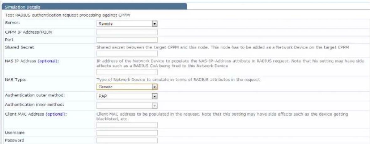
- Enter the values for each of the RADIUS Simulation parameters as described in Table 241.
Table 241: RADIUS Simulation Tab Parameters
| Parameter Action/Description | |
| Server 1. Specify Local or Remote. | |
| CPPM IP Address or FQDN | This field is displayed only if Remote Server is selected.2. Enter the IP address or the fully qualified domain name (FQDN) of the remote W-ClearPass Policy Manager server. |
| Shared Secret Displayed only if Remote Server is selected.3. Enter the shared secret between the target W-ClearPass server and this node. You must add the node as a Network Device on the target W-ClearPass server.(For details, see Adding a Network Device on page 464). | |
| NAS IP Address (optional) 4. | To populate the NAS-IP-Address attribute in a RADIUS request, enter the IP address of the network device. |
| NAS Type | 5. Select the type of network device to simulate in terms of RADIUS attributes in the request. The NAS types are:■ Dell Wireless Controller■ Dell Wired Switch■ Cisco Wireless Controller■ Generic |
| Authentication outer method | 6. Specify one of the following authentication outer methods:PAPCHAPMSCHAPv2PEAP: Authentication inner method: enabled.Select one of the following PEAP Authentication inner methods:EAP-MSCHAPv2EAP-GTCEAP-TLS |
| Parameter Action/Description | |
| • TTLS: Authentication inner method field: enabled.Select one of the following TTLS Authentication inner methods:■ PAP■ CHAP■ MSCHAPv2■ EAP-MSCHAPv2■ EAP-GTC■ EAP-TLS• TLS | |
| Client MAC Address (optional) | 7. Enter the client MAC address of the network device to populate the NAS-IP address attribute in the RADIUS request. |
| Username 8. Enter the user | name. |
| CA Certificate (optional) This | is the optional Root CA certificate needed to verify the RADIUS server's certificate.9. ClickBrowseand navigate to the optional Root CA certificate. ClickOpen, then clickUpload. |
| Client Certificate PKCS12 (PFX)* | This is the client certificate that is used for TLS in PKCS12 (Public-Key Cryptography Standards).Formats: .pfx or .p1210. ClickBrowseand navigate to the Client Certificate PKCS12. ClickOpen, then clickUpload. |
| Passphrase for PFX file* 11. | Enter the pass phrase for the selected PFX file. |
| * These fields are displayed only if you select TTLS or PEAP as the authentication outer method and you select EAP-TLS as the authentication inner method. | |
| 12. ClickSave, or clickNextto proceed to theAttributestab. | |
Setting the Attributes to Be Tested
The attributes that you can set depend on the NAS Type selected on the Policy Simulation page (see Figure 429).
To set the attributes to be tested:
-
From the Attributes tab, click Click to add.
The Add Policy Simulation Attributes dialog opens. -
From the Type drop-down, select the attribute Type.

Figure 430: Specifying Policy Simulation Attributes
Configuration » Policy Simulation » Add
Policy Simulation
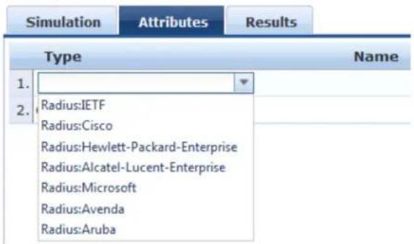
- Select the attribute Name.
- Select the attribute Value.
- Repeat these steps for each additional attribute you wish to add.
- Click Save, or click Next to proceed to the Results tab.
NAS Type: Aruba Wireless Controller
Figure 431: Aruba Wireless Controller Type - Attributes

Table 242: Dell Wireless Controller Required - Attribute Settings
| Attribute Parameter | |
| Line 1:Type = Radius:IETFName = NAS-Port-TypeValue = Wireless-802.11 (19) | |
| Line 2:Type = Radius:IETFName = Service-TypeValue = Login-User (1) | |
| Line 3:Type = Radius:ArubaName = Dell-Essid-NameValue = SSID | |
NAS Type: Aruba Wired Switch Controller
Figure 432: NAS Type: Aruba Wired Switch Controller Attributes Tab

Table 243: NAS Type: Aruba Wired Switch Controller—Required Attribute Settings
Attribute
Line 1:
• Type = Radius:IETF
• Name = NAS-Port-Type
• Value = Ethernet (15)
Line 2:
- Type = Radius:IETF
- Name = Service-Type
• Value = Login-User (1)
NAS Type: Cisco Wireless Switch
Figure 433: NAS Type: Cisco Wireless Switch Attributes
| Configuration > Policy Simulation > Add Policy Simulation | |||
| Simulation | Attributes | Results | |
| Type | Name | Value | # |
| 1. Radius: IETF | NAS-Port-Type | = Wireless-B02.11 (19) | Rb # |
| 2. Radius: IETF | Service-Type | = Framed-User (2) | Bp # |
Table 244: NAS Type: Cisco Wireless Switch Required Attribute Settings
Attribute
Line 1:
• Type = Radius:IETF
• Name = NAS-Port-Type
• Value = 802.11(19)
Line 2:
- Type = Radius:IETF
- Name = Service-Type
• Value = Framed-User(2)
Viewing the Simulation Results
The following figure displays the Policy Simulation RADIUS - Results dialog:
Figure 434: Results Tab
![Configuration > Policy Simulation > Edit - RAD Policy Simulation - RAD Simulation Attributes Results Summary - Authentication Result RADIUS Authentication successful Details View Details in Access Tracker Status - Status Message(s): Value: 15 ft-76 30 0e b4-49 af 9b SF S1 02 30 9e 5d bd 19 6b 80 00 00 00 00 52 30 30 30 30 30 31 66 2d 30 31 2d 35 32 63 65 33 37 38 32 00 00 00 00 00 00 00 00 00 STA 92:00:00:00:00:01; Received RADIUS packet matched with a pending request, round trip time 3.03 sec RADIUS packet matching with station MS-NMPE-Send-Key (sign) - hexdump(len=32): bc 71 00 3b 4d SS 46 9c e4 de S7 15 d5 ee ec dd 74 90 6e 9f a7 a6 f0 ef67 91 da S1 Sa fs e4 94 MS-NMPE-Recv-key (crypt) - hexdump(len=12): bb d4 4a da f1 d1 19 Sc da b8 b6 38 46 7f 11 33 of87 72 d7 d2 ba 3e b3 c4 00 28 57 07 75 ca af decapsulated EAP packet (code=3 id=9 len++) from RADIUS server: EAP Success EAPOL: Received EAP Packet frame EAPOL: SUPP_BE entering state REQUEST EAPOL: getSuppRep EAP: EAP entering state RECEIVED EAP: Received EAP Success EAP: EAP entering state SUCCESS CTRL-EVENT-EAP-SUCCESS EAP authentication completed sub EAPOL: IEEE B02.1X for plantext connection; na EAPOL-Key F WPA: EAPOL processing complete EAPOL: SUPP_DAE entering state AUTHENTICATED EAPOL: SUPP_BE entering state RECEIVE EAPOL: SUPP_BE entering state SUCCESS EAPOL: SUPP_BE entering state IDLE eapo_sn_dbi success=1 EAPOL: Successfully fetched key (len=32) PMK from EAPOL - hexdump(len=32): bb d4 4a da f1 d1 19 Sc EAP: denitalize previously used EAP method (1), TLS) at EAP ENGINE engine deint. MPRE keys OK: 1 mismatch: 0 SUCCESS Back to Policy Simulation Request Details Summary Xi Input Output Session Identifier: R0800001f-01-52ce3782 Date and Time: Jan 09, 2014 11:15:38 IST End-Host Identifier: 02-00-00-00-00-01 Username: zee1 Access Device IP/Port: 127.0.0.1: System Posture Status: UNKNOWN (IOC) Policies Used - Service: RSA Authentication Method: EAP-TLS Authentication Source: AD.pad.cppntest.com Authorization Source: RSA Roles: RSA, [User Authenticated] Enforcement Profiles: PANW-10, Pubic VLAN Service Monitoring Mode: Disabled Online Status: Not Available Change Status Export Show Logs Close](/content/2026/05/842116/images/c4c37050fd0881c3a298287b1d4c06d01291c7e8d49ea3b695b1ad1f485ecef1.jpg)
Table 245: RADIUS Authentication Results Tab Parameters
| Parameter Description | |
| Summary | Displays a summary of the simulation. |
| Authentication Result Displays the | outcome of the Authentication test. |
| Details | Click this link to open a dialog that provides details about the Authen test. You can take the following actions:Click the Summary, Input, or Output tabs.Click the Change Status, Show Logs, Export, or Close buttons. |
| Status Message(s) Displays the status messages resulting from the test. | |
Role Mapping Simulation
The role mapping simulation tests Role-Mapping policy rules to determine which roles will be output, give service name (and associated role mapping policy), the authentication source and the user name.
You can also use role mapping simulation to test whether the specified authentication source is reachable
Simulation Tab
The following figure displays the Role Mapping Simulation tab:
Figure 435: Role Mapping Simulation Tab
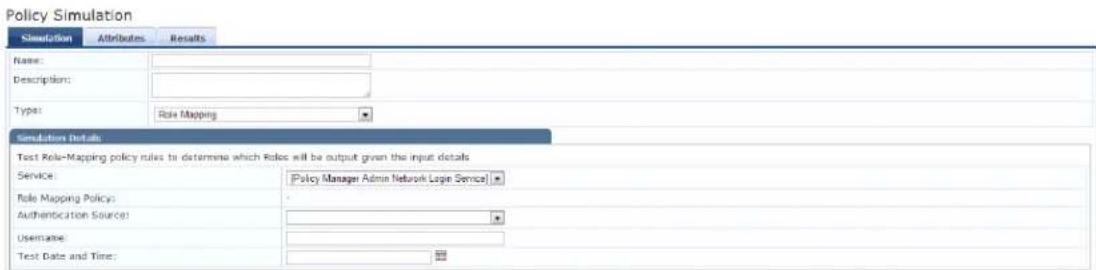
Table 246: Role Mapping Simulation Tab Parameters
| Parameter Description | |
| Service Select from: | [Policy Manager Admin Network Login Service][AirGroup Authorization Service][Aruba Device Access Service][Guest Operator Logins]Guest AccessGuest Access With MAC Caching |
| Role Mapping Policy | Field is disabled if you select:[Policy Manager Admin Network Login Service][Aruba Device Access Service][Guest Operator Logins]Field is auto-filled with [AirGroup Version Match] if you select [AirGroup Authorization Service]Field is autofilled with [Guest Roles] if you select Guest AccessField is autofilled with Guest MAC Authentication Role Mapping if you select Guest Access With MAC Caching |
| Authentication Source | Value = [Local User Repository] if you select:[Policy Manager Admin Network Login Service][Aruba Device Access Service]Value = [Guest Device Repository] if you select:[AirGroup Authorization Service]Guest AccessGuest Access With MAC CachingValues = [Guest Device Repository] or [Local User Repository] if you select [Gu Operator Logins] |
| Username Enter the user name. | |
| Test Date and Time Click calendar icon to select start date and time for simulation test. For more information, see Date Namespaces on page 926 | |
Attributes Tab
Enter the attributes of the policy component to be tested. The following figure displays the Role Mapping Simulation Attributes tab:
Figure 436: Role Mapping Simulation Attributes Tab

The following table describes the Role Mapping Simulation Attributes tab parameters:
Table 247: Role Mapping Simulation Attributes Tab Parameters
| Attribute Parameter | |
| Type Select the type of attributes from the drop-down list. | |
| Host | See Host Namespaces on page 927 |
| Authentication | See Authentication Namespaces on page 921 |
| Connection | See Connection Namespaces on page 925 |
| Application See | Application Namespace on page 920 |
| Certificate See | Certificate Namespaces on page 924 |
| Radius:IETFRadius:CiscoRadius:MicrosoftRadius:AvendaRadius:Aruba | See RADIUS Namespaces on page 928 |
| Name | The options displayed for the Name attribute depend on the Type attribute that was selected. |
| Value | The options displayed for the Value attribute depend on the Type Name attributes that were selected. |
Results Tab
The following figure displays the Role Mapping Simulation - Results tab:
Figure 437: Results Tab
Configuration » Policy Simulation » Edit - test2
Policy Simulation - test2
| Simulation | Attributes | Results |
| Summary - | ||
| Roles | [User Authenticated] | |
The following table describes the Role Mapping Simulation - Results tab parameters:
Table 248: Role Mapping Results Tab Parameters
| Parameter Description |
| Summary Displays the results of the simulation. |
Service Categorization Simulation
A service categorization simulation allows you to specify a set of attributes in the RADIUS or Connection namespace and test which configured service the request will be categorized into. The request attributes you specify represent the attributes sent in the simulated request.
Simulation Tab
The following figure displays the Service Categorization Simulation - Simulation tab:
Figure 438: Service Categorization Simulation Tab

Table 249: Service Categorization Simulation Tab Parameter s
| Parameter Type Namespace Details | |
| Test Date and Time Click calendar widget and select:Test start dateTest start time |
Attributes Tab
Enter the attributes of the policy component to be tested. The following figure displays the Service Categorization Simulation - Attributes tab:
Figure 439: Service Categorization Attributes Tab

Table 250: Service Categorization Simulation Attributes Tab Parameters
| Attribute Parameter | |
| Type Select the type of attributes from the drop-down list. | |
| Host | See Host Namespaces on page 927 |
| Authentication | See Authentication Namespaces on page 921 |
| Connection | See Connection Namespaces on page 925 |
| Application See | Application Namespace on page 920 |
| Radius:ETFRadius:CiscoRadius:MicrosoftRadius:Aruba | See RADIUS Namespaces on page 928 |
| Name | The options displayed for the Name attribute depend on the Type attribute that was selected. |
| Value | The options displayed for the Value attribute depend on the Type and Name attributes that were selected. |
Results Tab
The following figure displays the Service Categorization - Results tab:
Figure 440: Results Tab
Policy Simulation - service\_cat
| Simulation | Attributes | Results |
| Summary - | ||
| Service Name | ||
| Status - | ||
| Status Message(s) | No service found for request parameters | |
The following table describes the Service Categorization Simulation Results tab parameters:
Table 251: Service Configuration Results Tab Parameters
| Parameter Description | |
| Summary | Gives the name of the service. |
Import and Export Simulations
Navigate to Configuration > Policy Simulation and select the Import link. The following figure shows an example of the Import from file page.
Figure 441: Import Simulations
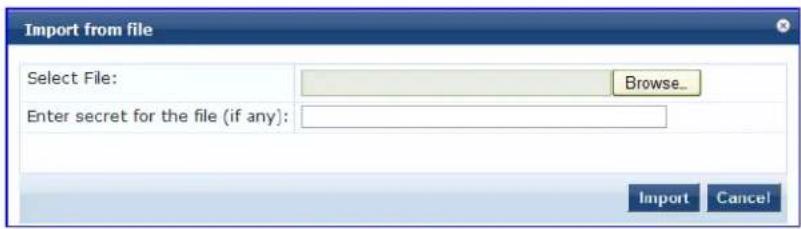
Table 252: Import from file page Parameters
| Parameter Description | |
| Select file Browse to select name of simulations to import. | |
| Enter secret for the file (if any) If the file was exported with a secret key for encryption, enter the same key here | |
Export Simulations
Click the Export All link to export all simulations. The browser displays the Save As dialog box in which you can enter the name of the XML file to export all simulations. The following image shows an example of Export page to file page.
Figure 442: Export Simulations
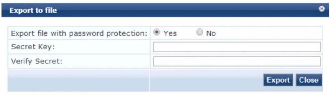
To export a specific simulation, click Export. In the Save As dialog box, enter the name of the XML file to contain the export data.
Table 253: Export Simulations
| Parameter Description | |
| Export file with password protection | Select Yes to export the file with password protection. |
| Secret Key | Enter the secret key in this field. |
| Verify Secret Enter the same secret key | to confirm and complete export. |
This chapter contains the following information:
• W-ClearPass Profile Overview
• About the Device Profile
• Endpoint Information Collectors
W-ClearPass Profile Overview
This section contains the following information:
- Introduction
• Enabling Endpoint Classification - Configuring CoA for an Endpoint-Connected Device
• How W-ClearPass Profile Classifies Endpoints
• Fingerprint Dictionaries
• Viewing Live Endpoint Information for a Specific Device
Introduction
W-ClearPass Profile is a W-ClearPass Policy Manager module that automatically classifies endpoints using attributes obtained from software components called Collectors.
W-ClearPass Profile associates an endpoint with a specific user or location and offers an efficient and ac-way to differentiate access by endpoint type (for example, laptop or tablet).
Profiling allows you to gather device type and operating system information by inspecting packets that are sent by these devices in the network. For example, you can identify that a device is a smart device, a printer or IP phone.
You can use this information to implement Bring Your Own Device (BYOD) flows during enforcement, ass the appropriate privileges and access to users based on their device type and the identity of the user.
Enabling Endpoint Classification
When you enable W-ClearPass Profile on a W-ClearPass server, you enable the server for endpoint classification. This associates each endpoint with a specific user or location and secures access for device. To enable W-ClearPass Profile:
- Navigate to Administration > Server Manager > Server Configuration.
The Server Configuration page opens.
- Select the W-ClearPass node in the zone that you want to designate as a Profiler.
The System tab for the Server Configuration page opens.
Figure 443: Enable Profile Option
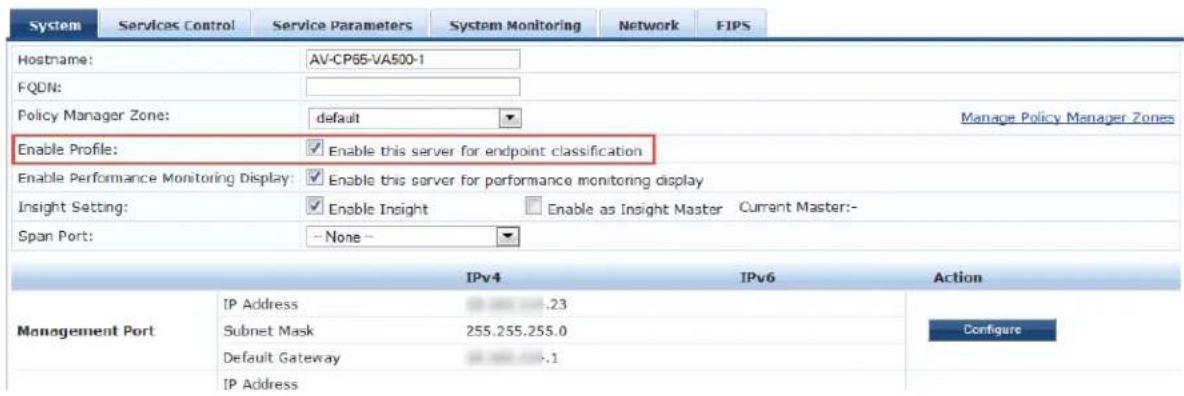
- If it is not already enabled, select the Enable this server for endpoint classification check box, then click Save.
Configuring CoA for an Endpoint-Connected Device
After profiling an endpoint, use the Profiler page to configure Change of Authorization (CoA) on the network device to which an endpoint is connected.
The Profiler tab is not displayed by default. To access the Profiler tab:
- Navigate to Configuration > Services, then click Add.
- Enter the name of the service.
- From the More Options field on the Service tab, enable the Profile Endpoints check box.
The Profiler tab is added to the Services tabs:
Figure 444: Adding the Profiler Page
Configuration » Services » Add
Services
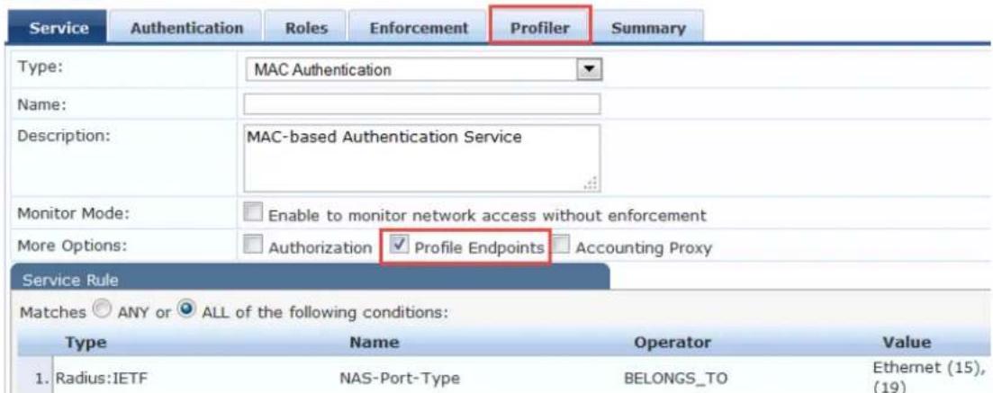
- Select the Profiler tab.
The Profiler page appears.
Figure 445: Profiler Page
![Service Authentication Roles Enforcement Profiler Summary Endpoint Classification: Select the classification(s) after which an action must be triggered - SmartDevice Home Audio/Video Equipment Projectors Remove -- Select -- RADIUS CoA Action: [Aruba Terminate Session] View Details Modify Add new RADIUS CoA Action Back to Services Next > Save Cancel](/content/2026/05/842116/images/bb1030571ba418492e43a1f9b451827f81c234a5464f3d2b630c142a4037ef33.jpg)
- You can select a set of categories and a CoA profile to be applied when the profile matches one of selected categories.
CoA is triggered using the selected CoA profile. You can use any option from Endpoint Classification t invoke CoA on a change of any one of the fields (category, family, and name).
Table 254 describes the Profiler page parameters:
Table 254: Profiler Page Parameters
| Parameter Action/Description | |
| Endpoint Classification 1. Select one or more endpoint classification items from the drop-down list.You can select a new action, or remove a current action. | |
| RADIUS CoA Action 2. Select the RADIUS CoA action from the drop-down list.3. To view the Policy Manager Entity Details page with the summary of enforcement profile details, click View Details.4. To view the Summary tab with profile details, click Modify. | |
| Add new RADIUS CoA Action | 5. To create a new RADIUS CoA action, click the Add New RADIUS CoA Actic link. |
- When finished, click Save.
How W-ClearPass Profile Classifies Endpoints
The W-ClearPass Profile module uses a two-stage approach to classify endpoints using input attributes.
Stage 1: Deriving Device Profiles
During Stage 1, W-ClearPass Profile derives device profiles using static dictionary lookups. Based on the available attributes available, Stage 1 looks up DHCP, HTTP, ActiveSync, MAC OUI, and SNMP dictionaries derives multiple matching profiles.
After multiple matches are returned, the priority of the source that provided the attribute is used to sell appropriate profile.
The following list shows the profile order of priority, from highest priority to lowest:
a. OnGuard/ActiveSync plugin
b. HTTP User-Agent
c. SNMP
d. DHCP
e. MAC OUI
Stage 2: Refining Results
W-ClearPass Policy Manager includes a set of rules that evaluates a device profile. The Rules engine uses input attributes and device profiles from Stage 1. The resulting rule evaluation may or may not result in profile. Stage 2 refines the results of profiling.
Example
With DHCP options, Stage 1 can identify an Android device. Stage 2 uses rules to combine this with the OUI to further classify an Android device as Samsung Android and HTC Android.
Fingerprint Dictionaries
W-ClearPass Policy Manager uses a set of dictionaries and rules to perform device fingerprinting.
Because these dictionaries can change frequently, W-ClearPass Policy Manager provides a way to automat update fingerprints from a hosted portal. The device fingerprints are updated from the Dell W-ClearPass Update Portal (for more information, see Software Updates and OnGuard Settings on page 693).
To view the contents of the fingerprints dictionary:
- Navigate to Administration > Dictionaries > Fingerprints.
The Device Fingerprints page opens. This page lists all the device fingerprints recognized by the Profile module.
Figure 446: Device Fingerprints Page
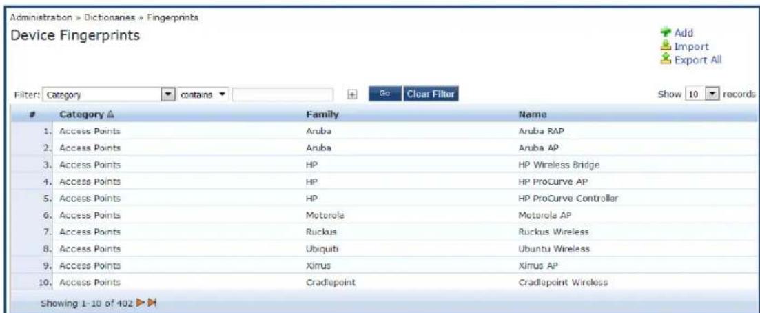
- To view the device fingerprint dictionary attributes, select the device fingerprint of interest. The attributes for the selected Device Fingerprint Dictionary are displayed:
Figure 447: Device Fingerprint Dictionary Attributes Page
![Device Fingerprint Dictionary Attributes Category: Access Points Family: Symbol Name: Symbol AP Field Value 1. DHCP Option55 [1,3,6,12,15,43,66,67,128,129,130,131,132,133,134,135] 2. DHCP Option60 [S24AP] 3. Nmap Device Type [[Symbol, WAP]] Close](/content/2026/05/842116/images/821e668c9ac55edb7295b1dd7a856a19a775d688bda80495e0da8eb5b9849877.jpg)
- To exit, click Close.
Viewing Live Endpoint Information for a Specific Device
The W-ClearPass Live Monitoring feature allows you to view endpoint information in graphic format for the device category, device family, and device name items you selected. You can also examine the endpoint and attributes about a specific device.
To access the Endpoint Profiler Live Monitoring information:
- Navigate to Monitoring > Profile and Discovery > Endpoint Profiler.
The Endpoint Profiler opens.
Figure 448: Endpoint Profiler
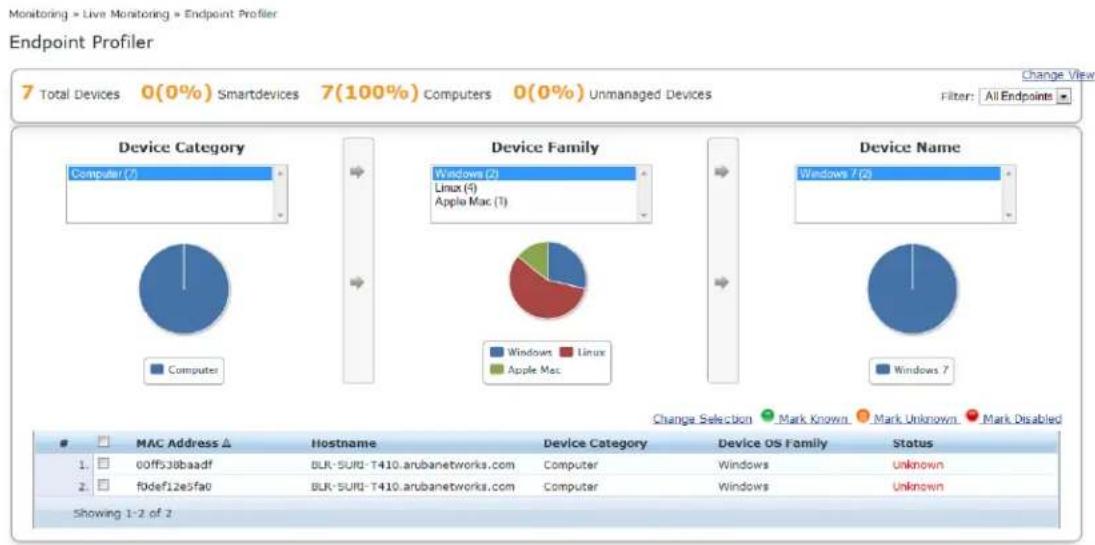
pie
| Device Category | Windows | Linux | Apple Mac | | :--- | :--- | :--- | :--- | | Windows (2) | 1 | 1 | 1 | | Linux (4) | 0 | 0 | 0 | | Apple Mac (1) | 0 | 0 | 0 | | Windows 7 (2) | 1 | 1 | 1 | | Windows 7 | 1 | 1 | 1 |-
To view endpoint details about a specific device, click a device in the table below the graphs.
-
To return to the Endpoint Profiler page, click Cancel.
For more information, see:
■ Profiler and Discovery: Endpoint Profiler on page 152
The Cluster Status Dashboard widget shows basic distribution of device types. For more information, s
About the Device Profile
A device profile is a hierarchical model consisting of three elements that are derived by the endpoint attributes—DeviceCategory, DeviceFamily, and DeviceName.
Table 255: Elements of a Device Profile
| Endpoint Attributes | Description |
| DeviceCategory Denotes the type of the device, for example, Computer, Smart Device, Printer, or Access Point. | |
| DeviceFamily Classifies devices based on the type of operating system or vendor. For example, when the category isComputer, W-ClearPass Policy Manager shows a device family of Windows, Linux, or Mac OS X. | |
| DeviceName Denotes the name of the device. Devices in a family are organized based on characteristics such as their operating system version. For example, in a DeviceFamily of Windows, W-ClearPass Policy Manager shows a DeviceName of Windows 8.1 or Windows Server 2012. | |
This hierarchical model provides a structured view of all endpoints accessing the network. In addition to a device profile also collects and stores the following:
IP address
- Host name
• Device vendor (via MAC OUI)
- Timestamp indicating when the device was first discovered
- Timestamp indicating when the device was last seen
Endpoint Information Collectors
Collectors are the network elements that provide data in order to profile endpoints. This section provides the following information:
- DHCP Collector
- NetFlow Collector
• W-ClearPass Onboard Collector - HTTP User-Agent Strings Collector
• MAC OUI Collector
• ActiveSync Plug-in Collector
• W-ClearPass OnGuard Agent
• About the Subnet Scan Collector - Configuring Subnet Scans
• SNMP Configuration for Wired Network Profiling - Accessing SSH and WMI Configuration Information
DHCP Collector
Dynamic Host Configuration Protocol (DHCP) attributes such as option 55 (parameter request list), option 60
(vendor class), and the options list from the Discover and Request packets can uniquely fingerprint most devices that use the DHCP mechanism to acquire an IP address on the network.
You can configure switches and controllers to forward DHCP Discover, Request, and Inform packets to W-ClearPass. These DHCP packets are decoded by W-ClearPass Policy Manager to arrive at the appropriate device category, OS family, and device name. In addition to fingerprints, DHCP also provides the host na and IP address.
Sending DHCP Traffic to the W-ClearPass Server
To configure your Dell controller and Cisco switch to send DHCP traffic to the W-ClearPass server, enter following CLI commands:
interface <vlan_name>
ip address <ip_addr> <netmask>
ip helper-address <dhcp_server_IO>
ip helper-address <clearpass_IP> end
end
You can configure multiple ip helper-address statements to send DHCP packets to servers other than the DHCP server.
NetFlow Collector
NetFlow provides the ability to collect IP network traffic as it enters or exits an interface. By analyzing the provided by NetFlow, a network administrator can determine things such as the source and destination of traffic, class of service, and the causes of congestion.
The W-ClearPass Policy Manager NetFlow Collector provides the ability to identify the open ports of a de connected to a network by analyzing the received NetFlow packets.
Supported versions are NetFlow v5 through v9 and IPFIX (Internet Protocol Flow Information eXport).
W-ClearPass Onboard Collector
W-ClearPass Onboard collects authentic device information from all devices during the onboarding process: Onboard then posts this information to the W-ClearPass Profile.
Because the information collected is definitive, W-ClearPass Profile can directly classify these devices into appropriate category, OS family, and name without having to rely on any other fingerprinting information
HTTP User-Agent Strings Collector
In some cases, DHCP fingerprinting alone cannot fully classify a device. A common example is the Apple of smart devices; for example, DHCP fingerprints cannot distinguish between an iPad and an iPhone.
In these scenarios, user-agent strings sent by browsers in the HTTP protocol are useful to further refine classification results.
User-agent strings are collected from the following:
• W-ClearPass Guest
• W-ClearPass Onboard
- Dell controller through an IF-MAP (Interface for Metadata Access Points) interface
MAC OUI Collector
The MAC OUI (Organization Unique Identifier) is expressed in the first 24 bits of a MAC address for a n connected device. Thus, the MAC OUI indicates the specific vendor for that device. The MAC OUI is acquired through various authentication mechanisms, such as 802.1X and MAC address authentication.
The MAC OUI can be useful to more accurately classify endpoints. An example is Android™ devices when DHCP fingerprints can only classify a device as generic Android, but it cannot provide more details regarding the vendor.
Combining this information with MAC OUI, the W-ClearPass Profiler can classify a device as HTC™ Android Samsung™ Android, or Motorola® Droid, etc.
The MAC OUI is also useful to profile devices such as printers that might be configured with static IP ac
ActiveSync Plug-in Collector
You can install the ActiveSync plug-in on Microsoft Exchange servers.
When a device communicates with an Exchange server using the Active Sync protocol, the device provides attributes such as device-type and user-agent.
These attributes are collected by the ActiveSync plug-in and sent to the W-ClearPass Profiler. Profiler use: dictionaries to derive profiles from these attributes.
W-ClearPass OnGuard Agent
The W-ClearPass OnGuard agent performs advanced endpoint posture assessment. This agent can collect send operating system details from endpoints during authentication.
The Policy Manager Profiler uses the OnGuard os_type attribute to derive a profile.
SNMP Collector
Endpoint information obtained by reading the Simple Network Management Protocol (SNMP) MIBs of network devices is used to discover and profile static IP devices in the network. For related information, see SNMP Configuration for Wired Network Profiling on page 459.
Table 256 describes the MIBs used by the SNMP Collector.
Table 256: SNMP MIBs Used by the SNMP Collector
| MIB Description | |
| SysDescr A textual description of the entity used both for profiling switches, controllers, and routers configured in W-ClearPass, and for profiling printers and other static IP devices discovered through SNMP or subnet scans (RFC1213). | |
| cdpCacheTable Provides the cached information obtained via receiving CDP (Cisco Discovery Protocol) messages from CDP-capable devices. Used to discover neighbor devices connected to the switch or controller configured in W-ClearPass. | |
| IldpRemTable This table contains one or more rows per physical network connection known to this agent read from LLDP (Link Layer Discovery Protocol)-capable devices. Used to discover and profile neighbor devices connected to the switch or controller configured in W-ClearPass. | |
| ARPtable Address Resolution Protocol (ARP) information read from the network devices. Used as a means to discover endpoints in the network. | |
Setting SNMP Community Attributes
The SNMP-based mechanism is capable of profiling devices only if they respond to SNMP, or if the device advertises its capability via LLDP (Link Layer Discovery Protocol). When performing SNMP reads for a device W-ClearPass uses SNMP Read credentials configured in the network devices, or defaults to using SNMPv2 "public" community strings specified.
To specify SNMPv2 with community strings:
- Navigate to Configuration > Network > Devices.
- From the Network Devices page, select the appropriate device.
The Edit Device Details dialog opens. - Select the SNMP Read Settings tab.
Figure 449: Specifying SNMP v2 with Community Strings

- Specify the SNMP Read Settings parameters as described in the following table, then click Save.
Table 257: SNMP Read Settings Parameters
| Parameter Action/Description | |
| Allow SNMP Read If not already enabled, enable the Allow SNMP Read check box.The SNMP Read Settings parameter fields are now enabled for configuration | |
| Policy Manager Zone Select the Policy Manager Zone. If no Policy Manager Zone is configured, select default. | |
| SNMP Read Setting Select SNMPv2 with community strings. | |
| Community String | Enter the Community String value, then reenter the string to verify it. |
| Force Read | Enable the Force Read check box to ensure that all W-ClearPass nodes in the cluster will read the SNMP information from this device, regardless of the trap configuration on the device.NOTE: This option is especially useful when demonstrating static IP-based device profiling because the Force Read option does not require any trap configuration on the network device. |
| Read ARP Table Info If this is a Layer-3 device, and you want to use the ARP table on this device as a way to discover endpoints in the network, enable the Read ARP Table Info check box.NOTE: Static IP endpoints discovered in this way are further probed via SNMP to profile the device. | |
Configuring the Device Info Poll Interval
Network devices configured with SNMP Read enabled are polled periodically for updates based on the time interval configured in the Device Info Poll Interval.
To set the Device Info Poll Interval:
- Navigate to Administration > Server Manager > Server Configuration.
- Select the W-ClearPass server of interest.
The Server Configuration page opens. - Select the Service Parameters tab.
- From the Select Service drop-down, select W-ClearPass network services.
The W-ClearPass network services page opens.
Figure 450: Specifying the Device Info Poll Interval
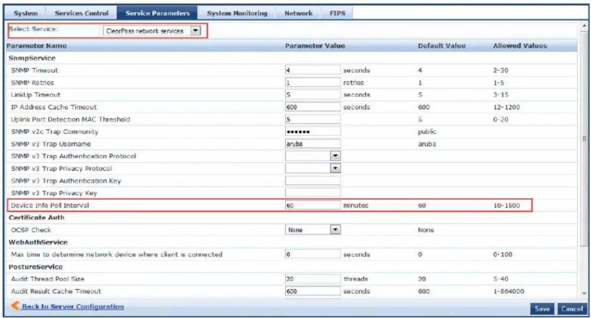
- In the minutes field, enter the Device Info Poll Interval, then click Save.
About the Subnet Scan Collector
A network subnet scan discovers the IP addresses of devices in the network.
The devices discovered in this way are further probed using SNMP to fingerprint and assign a profile to device. Network subnets to be scanned are configured per Policy Manager Zone.
This is particularly useful in deployments that are geographically distributed. In such deployments, it is recommended that you complete the following tasks:
- Assign the W-ClearPass Policy Managernodes in a cluster to multiple zones depending on the geographic area served by that node.
To set up Policy Manager Zones, navigate to Administration > Server Manager > Server Configuration > Manage Policy Manager Zones.
- Then enable the profile for a minimum of one node per zone.
For more information, see Managing Policy Manager Zones on page 541.
Configuring Subnet Scans
When you configure subnet scans, you specify the IP subnets that you want to be scanned for discoverin hosts in the network and their capabilities. You have two options:
- Schedule a subnet scan
- Initiate an on-demand subnet scan
Scheduling a Subnet Scan
To schedule a subnet scan:
- Navigate to the Configuration > Profile Settings page.
The Profile Settings page opens to the Subnet Scans page.
Figure 451: Subnet Scans Page

- Click the Schedule Subnet Scan link.
The Schedule Subnet Scan dialog opens.
Figure 452: Scheduling a Subnet Scan
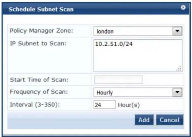
- Configure the Schedule Subnet Scan parameters as described in the following table. When finished, click Add.
Table 258: Schedule Subnet Scan Parameters
| Parameter Action/Description | |
| Policy Manager Zone | Select the Policy Manager Zone.NOTE:If Policy Manager Zones have not yet been set up, you can select thedefaultzone, which will allow you to proceed with the subnet scan configuration procedure. For details, seeManaging Policy Manager Zones on page 541. |
| IP Subnet to Scan Enter the IP addresses for the subnets you wish to scan (using comma-separated values). | |
| Start Time of Scan Specify the time at which the subnet scan should start the first time.When you click this field, a time calendar opens, from which you can select the start time | |
| Frequency of Scan Choose one of the following options to specify the subnet scan's frequency:Hourly: This is the default setting.DailyWeekly: When you select Weekly, the Select Day of Weekfield appears. Select the day of the week you want the scans to occur. | |
| Interval | This option is displayed when you select Hourlyfor the scan frequency. Specify the profile subnet scan interval in hours.The default value is24 hours. The range is from 3 to 350 hours. |
You return to the Subnet Scans page, where the IP subnets are listed, along with their Policy Manager zone (if specified) and the subnet scan schedule:
Figure 453: Subnet Scan Configured

Initiating an On-Demand Subnet Scan
In cases in which you wish to initiate a subnet scan without saving the configuration, you can run an O Demand Subnet Scan.
To run an On-Demand Subnet Scan:
- Navigate to Configuration > Profile Settings.
The Profile Settings page opens to the Subnet Scans tab.
Figure 454: Initiating an On-Demand Subnet Scan

- Click the On-Demand Subnet Scan link.
The Initiate On-Demand Subnet Scan dialog opens.
Figure 455: Initiate On-Demand Subnet Scan Dialog
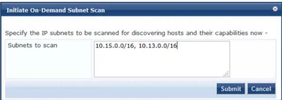
-
To discover hosts, specify the IP subnets to be scanned in the Subnets to scan text field. Separate multiple subnets with commas.
-
Click Submit.
The subnet scan progress is shown on the Profile Settings page. You can view the subnet scan events in the Monitoring > Event Viewer page.
Figure 456: Subnet Scan Logs
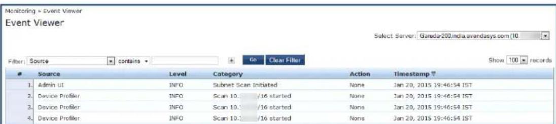
SNMP Configuration for Wired Network Profiling
For wired network profiling, you can configure a list of multiple SNMP community strings to query static address devices discovered by the Profiler.
If a static IP address device does not respond to queries from the default public community string, the service can use the credentials from this custom list to query the device.
To configure SNMP for wired network profiling:
- Navigate to Configuration > Profile Settings.
- Click the SNMP Configuration tab.
Figure 457: Profile Settings > SNMP Configuration Page

- Click Add SNMP Configuration.
The SNMP Configuration dialog opens.
Figure 458: Configuring SNMP Community Strings
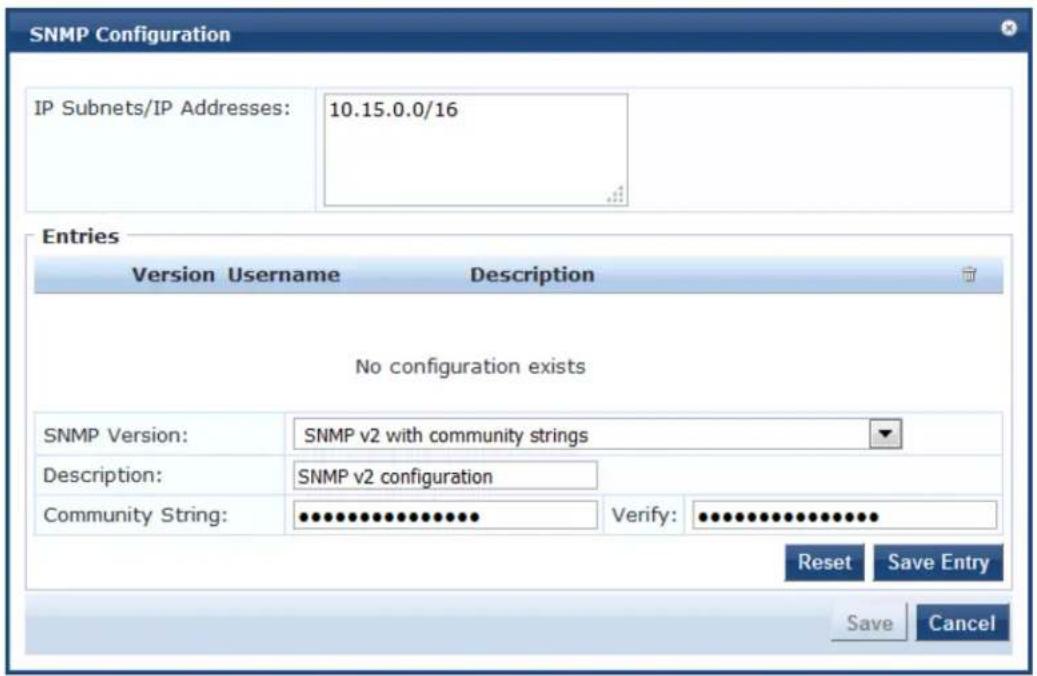
- Specify the SNMP Configuration parameters as described in the following table, click Save Entry, then click Save:
Table 259: SNMP Configuration Parameters
| Parameter Action/Description | |
| IP Subnets/IP Addresses | Enter one or more IP subnet addresses and their subnet masks. For multiple entries, separate multiple IP addresses with commas. |
| SNMP Version | From the drop-down, select the appropriate SNMP version. |
| Description Optionally, | enter a description of this SNMP configuration (recommended). |
| Community String | Enter the community string, then reenter the community string in the Verify field. |
Accessing SSH and WMI Configuration Information
For information on configuring SSH and WMI credentials:
- SSH credentials
For Linux server or network device discovery, specify SSH configuration credentials. For more information see SSH Credentials Configuration on page 156.
• WMI credentials
For Windows device discovery, specify WMI (Windows Management Instrumentation) credentials. For more information, see WMI Credentials Configuration on page 158.
This chapter describes the following tasks that you can perform by using the Policy Manager user interface
- Adding and Modifying Network Devices on page 464
- Adding and Modifying Device Groups on page 474
- Adding and Modifying Proxy Targets on page 473
- Configuring the Ingress Event Sources on page 732
Introduction
A Policy Manager device represents a Network Access Device (NAD) that sends network access requests to Policy Manager using the supported RADIUS, TACACS+, or SNMP protocol. You can add or modify a device group from the Policy Manager server.
For related information, see SNMP Private MIB, SNMP Traps, System Events, Error Codes on page 867.
For the Policy Manager server to discover and access the network devices, you must perform the followi tasks:
- Configure SNMP read credentials on the network device to enable Policy Manager server to query against network devices or perform SNMP write operations. For details, see SNMP Credentials Configuration on page 154.
- Configure SNMP trap configurations on the network device to send SNMP traps to the Policy Manager server. For details, see SNMP Trap Receivers on page 581.
- Ensure that the same SNMP Trap credentials are configured in the SnmpService section under the Administration > Server Configuration > Service Parameters tab of the Policy Manager user interface.
- Configure SNMPTRAPD on the Policy Manager server to receive SNMP traps. For details, see SNMP Private MIB, SNMP Traps, System Events, Error Codes on page 867.
For SNMP enforcement on the network device, one or more of the following traps must be configured: the device:
■ Link Up trap
■ Link Down trap
■ MAC Notification trap
In addition, the device must also support one or more of the following SNMP MIBs:
RFC-1213 MIB
■ IF-MIB, BRIDGE-MIB
ENTITY-MIB
Q-BRIDGE-MIB
CISCO-VLANMEMBERSHIP-MIB
CISCO-STACK-MIB
CISCO-MAC-NOTIFICATION-MIB
These traps and MIBs enable Policy Manager to correlate the MAC address, IP address, switch port, a switch information.
- Configure SSH CLI data on the Policy Manager server to allow a phantom login to network devices. For details, see SSH Credentials Configuration on page 156.
- Configure DHCP Relay configuration on the network device to ensure that DHCP requests are forwarded from the clients. For more information, see DHCP Collector on page 453.
Adding and Modifying Network Devices
This section provides the following information:
- Adding a Network Device
- Adding and Modifying Proxy Targets
- Adding and Modifying Device Groups
- Configuring the Ingress Event Sources
A Network Access Device (NAD) must belong to the global list of devices in the Policy Manager database order to connect to Policy Manager using any of the supported protocols.
The Policy Manager Network Devices page displays the device name, IP address or subnet address, and a brief description of each configured device.
- To view this page, navigate to Configuration > Network > Devices.
The Network Devices page opens:
Figure 459: Network Devices Page
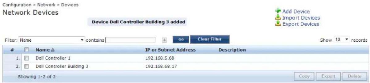
For information on configuring a new network device, see Adding a Network Device on page 464.
Adding a Network Device
This section describes how to configure a new network device:
• Device Parameters
• SNMP Read Settings Parameters
• SNMP Write Settings Parameters
• CLI Settings Parameters
• Enabling W-ClearPass OnConnect Enforcement on a Network Device
- Querying and Selecting Port Names for OnConnect Enforcement
• Attributes Parameters
To add a network device:
- Navigate to the Configuration > Network > Devices page.
The Network Devices page opens.
Figure 460: Network Devices Page
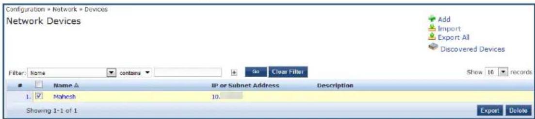
- Click the Add link at the top-right corner.
The Add Device page opens.
Device Parameters
Figure 461: Add Device > Device Dialog
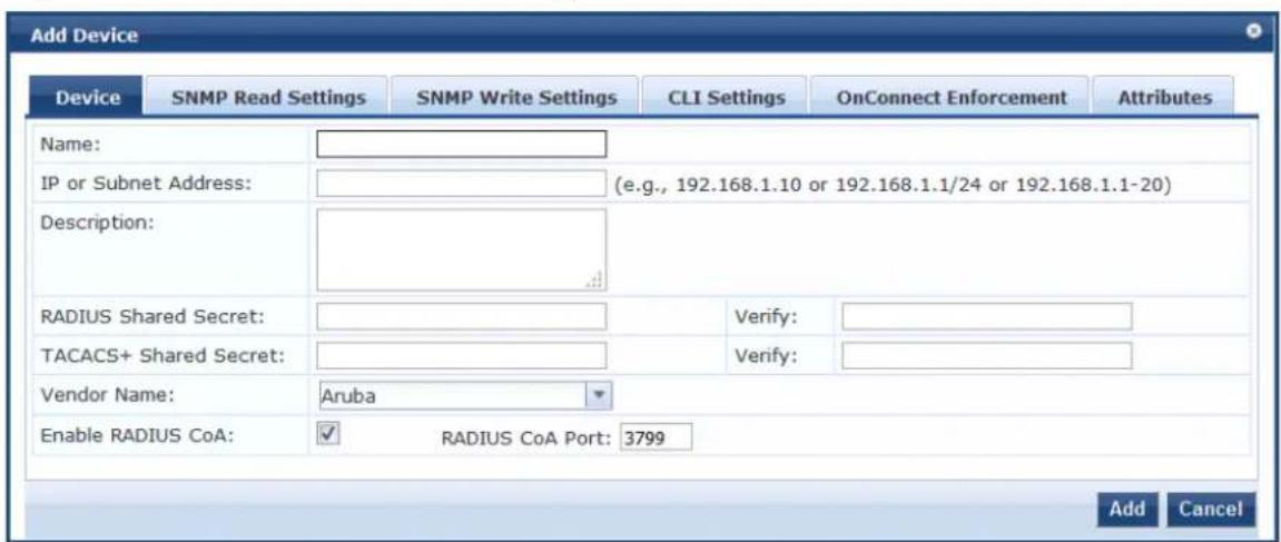
- Enter the Add Device > Device parameters as described in Table 260:
Table 260: Add Device > Device Parameters
| Parameter Action/Description | |
| Name Enter the name of the device. | |
| IP Address or Subnet | Specify the IP address or the subnet of the device.You can use a hyphen to indicate the range of device IP addresses following the format a.b.c.d-e. For example, 192.168.1.1-20. |
| Description Enter a description that provides additional information to identify the device. | |
| RADIUS Shared Secret | Enter the RADIUS shared secret. |
| TACACS+ Shared Secret | Enter the TACACS+ shared secret. |
| Vendor Name Specify | the name of the vendor to load the dictionary associated with this vendor for this device.This field is optional.NOTE: RADIUS:IETF, the dictionary containing the standard set of RADIUS attrib is always loaded. When you specify a vendor here, the RADIUS dictionary assoc with this vendor is automatically enabled. |
| Enable RADIUS CoA | To configure the UDP port on the device to send CoA (Change of Authorization) actions, enable RADIUS CoA for this device.RADIUS CoA Port: The default value is 3799. |
SNMP Read Settings Parameters
Use the SNMP Read Settings tab to define values that allow W-ClearPass Policy Manager to read information from the device using SNMPv1, SNMPv2, or SNMPv3.
Large or geographically-spread cluster deployments typically do not require each W-ClearPass node to probe all SNMP configured devices. By default, a W-ClearPass node in a cluster only reads network device information for devices configured to send traps to that node.
- From the Add Device page, select the SNMP Read Settings tab.
The SNMP Read Settings dialog opens:
Figure 462: Add Device > SNMP Read Settings Dialog
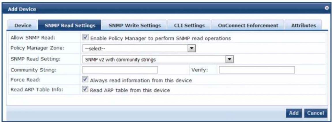
- Enter the SNMP Read Settings parameters as described in Table 261:

Table 261: Add Device > SNMP Read Settings Parameters
| Parameter Action/Description | |
| Allow SNMP Read | Toggle to enable or disable SNMP Read operations. |
| Policy Manager Zone | You can assign Network Access Devices to a zone, allowing the SNMP service to poll or query only the NADs that are in its zone.From the Policy Manager Zone drop-down, select the zone assigned to the network device that is being added.OnConnect Enforcement is triggered when a trap from a NAD is received by a W-ClearPass node.If the zone assigned to a W-ClearPass node is not same as the zone configured here, then OnConnect Enforcement is not triggered on that W-ClearPass node.NOTE: This setting can be empty or null. |
| SNMP Read Setting | Specify one of the following SNMP Read Settings:SNMP v1 with community stringsSNMP v2 with community stringsSNMP v3 with no AuthenticationSNMP v3 with Authentication using MD5 and no PrivacySNMP v3 with Authentication using MD5 and with PrivacySNMP v3 with Authentication using SHA and no PrivacySNMP v3 with Authentication using SHA and with PrivacyNOTE: The MD5 authentication type is not supported when you use W-ClearPass Policy Manager in FIPS mode. |
| Community String | Enter the community string for sending the traps.NOTE: Available in SNMP v2 only. |
| Verify | Reenter the community string for sending the traps. |
| Force Read | EnableForce Readto ensure that all W-ClearPass Policy Manager nodes in the cluster read SNMP information from this device regardless of the trap configuration on the device.This option is useful when demonstrating a static IP-based device profiling because this does not require any trap configuration on the network device.NOTE: Available in SNMP v1 and SNMP v2 only. |
| Read ARP Table Info | Enable this setting on a Layer-3 device if you intend to use the ARP table on this device to discover endpoints in the network.static IP endpoints that are discovered this way are probed using SNMP to profile the device. |
| Username Specify the Admin user name to use for SNMP read operations.NOTE: Available in SNMP v3 only. | |
| Authentication Key | Specify the SNMP v3 with authentication option (SHA or MD5).NOTE: The EAP-MD5 authentication type is not supported if you run W-ClearPass Policy Manager in FIPS mode.NOTE: Authentication Key is available in SNMP v3 only. |
| Privacy Key Specify the SNMP v3 with privacy option.NOTE: Available in SNMP v3 only. | |
| Privacy Protocol | Choose one of the available privacy protocols:■ DES-CBC■ AES-128NOTE: Available in SNMP v3 with Privacy only. Privacy allows for encryption of SNMP v3 messages to ensure confidentiality of data. |
SNMP Write Settings Parameters
Use the SNMP Write Settings tab to define values that allow W-ClearPass Policy Manager to write to (manage) the device using SNMPv1, SNMPv2, or SNMPv3.
- From the Add Device page, select the SNMP Write Settings tab.
The SNMP Write Settings dialog opens:
Figure 463: Add Device > SNMP Write Settings Dialog
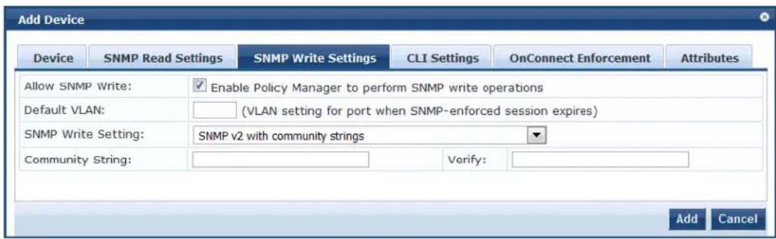
- Enter the SNMP Write Settings parameters as described in Table 262.
Table 262: Add Device > SNMP Write Settings Parameters
| Parameter Action/Description | |
| Allow SNMP Write | Toggle to enable or disable SNMP write. |
| Default VLAN | Specify the VLAN port setting after the SNMP-enforced session expires. |
| SNMP Write Setting | Specify the SNMP Write setting for the device. You can set any of the following options■ SNMP v1 with community strings■ SNMP v2 with community stringsSNMP v3 with no AuthenticationSNMP v3 with Authentication using MD5 and no PrivacySNMP v3 with Authentication using MD5 and with PrivacySNMP v3 with Authentication using SHA and no PrivacySNMP v3 with Authentication using SHA and with PrivacyNOTE:The MD5 authentication type is not supported if you use W-ClearPass Policy Man in FIPS mode. |
| Community String | Enter the community string for sending the traps. |
| Verify Reenter the community string for sending the traps. | |
CLI Settings Parameters
Use the CLI Settings tab to enable or disable the CLI, and define user names, passwords, and port settings for accessing the CLI.
- From the Add Device page, select the CLI Settings tab.
The CLI Settings dialog opens:
Figure 464: Add Device > CLI Settings Dialog
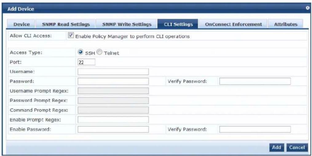
- Enter the CLI Settings parameters as described in Table 263:
Table 263: Add Device > CLI Parameters
| Parameter Action/Description | |
| Allow CLI Access Toggle to enable or disable CLI access. | |
| Access Type Select SSH or Telnet.Policy Manager uses the selected access method to log into the device CLI. | |
| Port Specify the SSH or Telnet TCP port number. | |
| Username Enter the username to log into the CLI. | |
| Password Enter the password to log into the CLI. | |
| Username Prompt Regex | Specify the regular expression for the username prompt.Policy Manager looks for this pattern to recognize the Telnet username prompt. |
| Password Prompt Regex | Specify the regular expression for the password prompt.Policy Manager looks for this pattern to recognize the Telnet password prompt. |
| Command Prompt Regex | Specify the regular expression for the command line prompt.Policy Manager looks for this pattern to recognize the Telnet command-line prompt. |
| Enable Prompt Regex | Specify the regular expression for the command line in the enable prompt.Policy Manager looks for this pattern to recognize the Telnet command-line prompt. |
| Enable Password | Enter then reenter the credentials for the Enable password in the CLI. |
Enabling W-ClearPass OnConnect Enforcement on a Network Device
OnConnect Enforcement is an enforcement model that allows you to use non-802.1X methods for device scans, VLAN placement, and so on. OnConnect Enforcement allows enforcement in non-802.1X environments without the need for an agent (such as OnGuard) on the endpoint.
When this feature is enabled, W-ClearPass performs the following actions:
• Detects when a new endpoint connects to the network.
- Scans the endpoint to identify the logged-in user and other device-specific information.
- Triggers a Web-based authentication (WebAuth) for the device.
• Performs SNMP-based enforcement to change the network access profile for the device.
To enable W-ClearPass OnConnect Enforcement on a network device:
- From the Add Device page, select the OnConnect Enforcement tab.
The OnConnect Enforcement dialog opens:
Figure 465: Add Device > OnConnect Enforcement Dialog
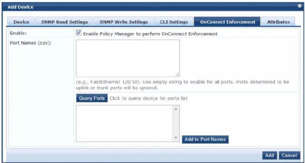
- Enter the OnConnect Enforcement parameters as described in Table 264.
Table 264: Add Device > OnConnect Enforcement Parameters
| Parameter | Action/Description |
| Enable Select | this check box to enable W-ClearPass OnConnect on the network access device being added. |
| Port Names | Specify the names and descriptions of the ports to be enabled for OnConnect Enforcement (see the next section for details). You can do so in two ways:Click Query Ports.You can also a enter port names manually as a comma-separated list.Only the ports added in the Port Names field will have OnConnect Enforcement enabled.For example, if you add the port names Fa1/0/3,Fa1/0/5, when clients connect to any of these ports on the specified network device, OnConnect Enforcement is triggered on that network device.NOTE: An empty string will enable OnConnect on all ports. W-ClearPass will attempt to determine the uplink or upstream trunk ports; however, it is recommended to explicitly remove those ports. |
| Query Ports | To display the list of ports on the current server, click Query Ports. |
| Add to Port Names | Once the list of ports are displayed, select the desired ports from the displayed list, then click Add to Port Names.The selected ports are added to the Port Names field. |
Querying and Selecting Port Names for OnConnect Enforcement
To query and select port names for a network access device for OnConnect Enforcement:
- From the Configuration > Network > Devices page, select the network device.
- From the Edit Device Details page, select the SNMP Read Settings tab (see Table 261 above).
- In the Allow SNMP Read parameter, select the Enable Policy Manager to perform SNMP read operations check box.
- Select the OnConnect Enforcement tab.
- Click the Query Ports button.
The list of ports are displayed, as shown in Figure 466.
Figure 466: Querying Ports
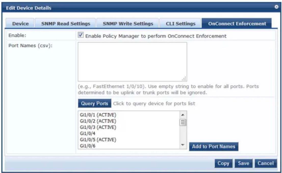
- Select the ports to use, then click Add to Port Names.
The selected port names are added to the Port Names list. Only the ports added in the Port Names field will have OnConnect Enforcement enabled.
- Click Save.
Attributes Parameters
To add custom attributes for this device:
- From the Add Device page, select the Attributes tab.
The Attributes dialog opens:
Figure 467: Adding Custom Device Attributes
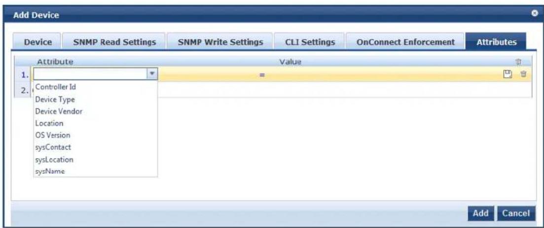
- From the Attribute field, click Click to add....
By default, the following custom attributes appear in the Attribute drop down:
Controller ID
■ Device Type
■ Device Vendor
Location
OS Version
sysContact
sysLocation
sysName
- Select one of the default attributes or enter a new attribute.
You can enter any name in the Attribute field. All attributes are of string datatype.
- Specify the attribute's value.
You can populate the Value field with any string.
-
Repeat this procedure as necessary.
-
When finished adding custom attributes, click Add.
All attributes entered for a device are available in the role-mapping Rules Editor under the Device namespace.
Adding and Modifying Proxy Targets
A proxy server is a dedicated computer or a software system running on a computer that acts as an
intermediary between an endpoint device, such as a computer, and another server from which a user or is requesting a service. The proxy server can exist in the same machine as a firewall server or it can be separate server, which forwards requests through the firewall.
In W-ClearPass Policy Manager, a proxy target represents a RADIUS server (Policy Manager or a third party) that is the target of a proxied RADIUS request.
For example, when a branch office employee visits a main office and logs into the network, Policy Mana, assigns the request to the first service in priority order that contains a service rule for RADIUS proxy se and appends the domain to the username.
Proxy targets are configured at a global level. They can be used in configuring RADIUS proxy services. For information, refer to Configuring Policy Manager Services on page 72.
Adding a Proxy Target
To add a proxy target:
- Navigate to Configuration > Network > Proxy Targets.
The Proxy Targets page opens. Policy Manager lists all configured proxy servers in the Proxy Targets page.
- Click Add.
The Add Proxy Target dialog opens.
Figure 468: Add Proxy Target Dialog
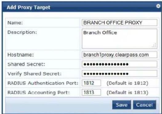
- Specify the Add Proxy Target parameters as described in the following table, then click Save:
Table 265: Add Proxy Target Parameters
| Parameter Action/Description | |
| Name Enter the name of the proxy target. | |
| Description Enter the description that provides additional information about the proxy target. | |
| Hostname/Shared Secret | Specify the RADIUS hostname. |
| Shared Secret Verify Shared Secret | Enter the shared secret, then verify it.NOTE: Use the same shared secret that you entered on the proxy target (refer to your RADIUS server configuration). |
| RADIUS Authentication Port | Enter the UDP port to send the RADIUS request. The default value for this port is 1812. |
| RADIUS Accounting Port | Enter the UDP port to send the RADIUS accounting request. The default value for this port is 1813. |
Adding and Modifying Device Groups
Policy Manager groups devices into Device Groups, which function as a component in service and role mapping rules. Device groups can also be associated with enforcement profiles; Policy Manager sends the attributes associated with these profiles only if the request originated from a device belong to the device groups.
Administrators configure device groups at the global level. Device groups can contain the members of the address of a specified subnet, regular expression-based variation, or devices that are previously configured the Policy Manager database.
Policy Manager lists all configured device groups in the Device Groups page (Configuration > Network > Device Groups). The following figure displays the Network Device Groups page:
Figure 469: Device Groups Page
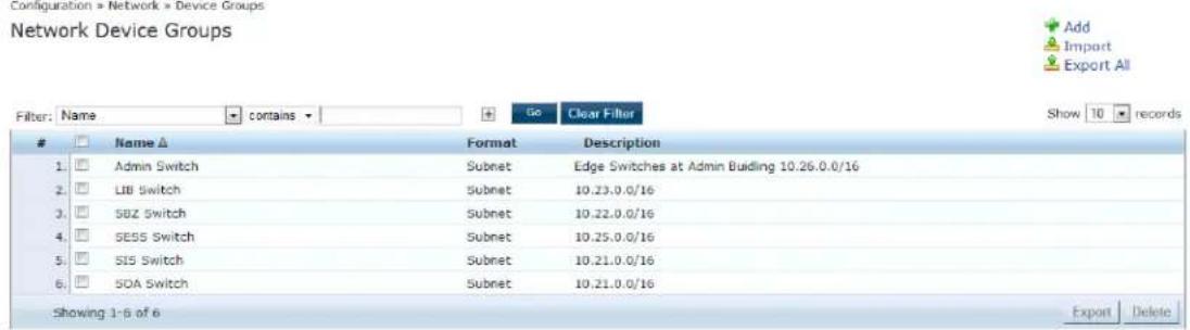
To add a device group, click Add at the top-right corner of the Network Device Groups page. Complete the fields in the Add New Device Group page as described in the following figure:
Figure 470: Add New Device Group Page
![Add New Device Group Name: Test Device Group Description: This is a test device group Format: Subnet Regular Expression List Subnet: (e.g., 192.168.1.1/24) Add New Device Group Name: TestDevice Group 2 Description: This is a test device group 2 Format: Subnet Regular Expression List Regular Expression: (e.g., ^192([0-9]*){3)$) Add New Device Group Name: TestDevice Group 2 Description: This is a test device group 2 Format: Subnet Regular Expression List List: Available Devices - Filter 192.168.150.204 192.168.150.60 192.168.150.80 192.168.5.12 192.168.5.208 192.168.5.214 Selected Devices - Filter Save Cancel](/content/2026/05/842116/images/7e95638a39a1a7c562ac0fb2ec67e6aed83be55017db40b00773defc14cb0117.jpg)
The following table describes the Add New Device Group page parameters:
Table 266: Add New Device Group Page
| Parameter Description | |
| Name Enter the name of the device group. | |
| Description Enter the description that provides additional information about the device group. | |
| Format Select the format: Subnet, Regular Expression, or List. | |
| Subnet Enter a subnet consisting of network address and the network suffix (CIDR notation). For example, 192.168.5.0/24. | |
| Regular Expression | Specify a regular expression that represents all IPv4 addresses matching that expression For example, ^192{.[0-9]*){3}$. |
| List: Available/Selected Devices | Use the widgets to move device identifiers between Available and Selected. Click Filter to filter the list based on the text in the associated text box. |
Configuring the Ingress Event Sources
The Event Source is the device that sends Syslog events to W-ClearPass. Any events sent that are not fr configured event sources are ignored.
To configure the Event Source (in this example, a Juniper Networks SRX gateway):
- Navigate to Configuration > Network > Event Sources.
The Event Sources page opens.
- To add the Event Source for the desired vendor, click Add.
The Add Events Source dialog opens.
Figure 471: Adding an Event Source
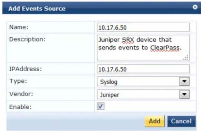
- Specify the Add Event Source parameters as described in Table 267.
Table 267: Configuring the Event Source Parameters
| Parameter Action/Description | |
| Name 1. Enter the IP address of the device that will send Syslog events to W-ClearPass. | |
| Description Optionally, enter a description of this Event Source. | |
| IP Address 2. Enter the IP address of the device that will send Syslog events to W-ClearPass. | |
| Type 3. From the drop-down, select the Event Source Type. | |
| Vendor 4. From the drop-down, select the Event Source Vendor. | |
| Enable 5. Select this check box to enable the device as an Event Source. |
6. When finished, click Add.
The Event Sources page now displays the new Event Sources (see Figure 472).
Figure 472: Event Sources Page
Configuration » Network » Events Sources
Events Sources




The IP address displayed in Figure 472 is the IP address and host name of the Juniper SRX gateway that sends Syslog events to W-ClearPass.
You can access all W-ClearPass administrative activities, including server configuration, log management, certificate and dictionary maintenance, portal definitions, and administrator user account maintenance from the following Administration sections:
• W-ClearPass Portal
■ W-ClearPass Guest Portal on page 480
• Services
■ Services on page 1
- Users and Privileges
■ Managing Admin Users on page 481
■ Managing Admin Privileges on page 486
- Server Manager
■ Server Configuration on page 494
■ Log Configuration on page 567
■ Downloading Local Shared Folders on page 570
■ License Management on page 571
• External Servers
■ SNMP Trap Receivers on page 581
■ Syslog Targets on page 587
■ Syslog Export Filters on page 591
■ Messaging Setup on page 603
■ Endpoint Context Servers on page 606
■ File Backup Servers on page 669
- Certificates
■ Server Certificates on page 671
■ Certificate Trust List on page 681
■ Certificate Revocation Lists on page 683
- Dictionaries
■ RADIUS Dictionary on page 685
■ TACACS+ Services Dictionary on page 686
■ Device Fingerprints Dictionary on page 688
■ Dictionary Attributes on page 689
■ Applications Dictionaries on page 934
■ Configuring Endpoint Context Server Actions on page 614
• Agents and Software Updates
■ OnGuard Settings and OnGuard Custom Web Pages on page 699
■ Software Updates
■ OnGuard Global Agent Settings on page 708
- OnGuard
■ Accessing the OnGuard Support Charts on page 739
■ Upgrading From OnGuard Plugin Version 1.0 to 2.0 on page 740
■ Native Dissolvable Agent Supported Operating Systems and Browsers on page 759
• Insight Report Tool
■ W-ClearPass Insight Reports on page 769
- Support
■ Contacting Support on page 1
■ Remote Assistance on page 1
■ Accessing Documentation on page 1
■ Accessing the OnGuard Support Charts on page 739
- Cluster Update and Upgrade Tools
■ About the Cluster Update Tool on page 713
■ About the Cluster Upgrade Tool on page 718
• Ingress Events Processing
■ Configuring Processing for Ingress Events on page 1
W-ClearPass Guest Portal
To customize the W-ClearPass Guest Portal content for your enterprise:
1. Navigate to the Administration > W-ClearPass Portal page.
The following figure displays the W-ClearPass Guest Portal page:
Figure 473: W-ClearPass Guest Portal
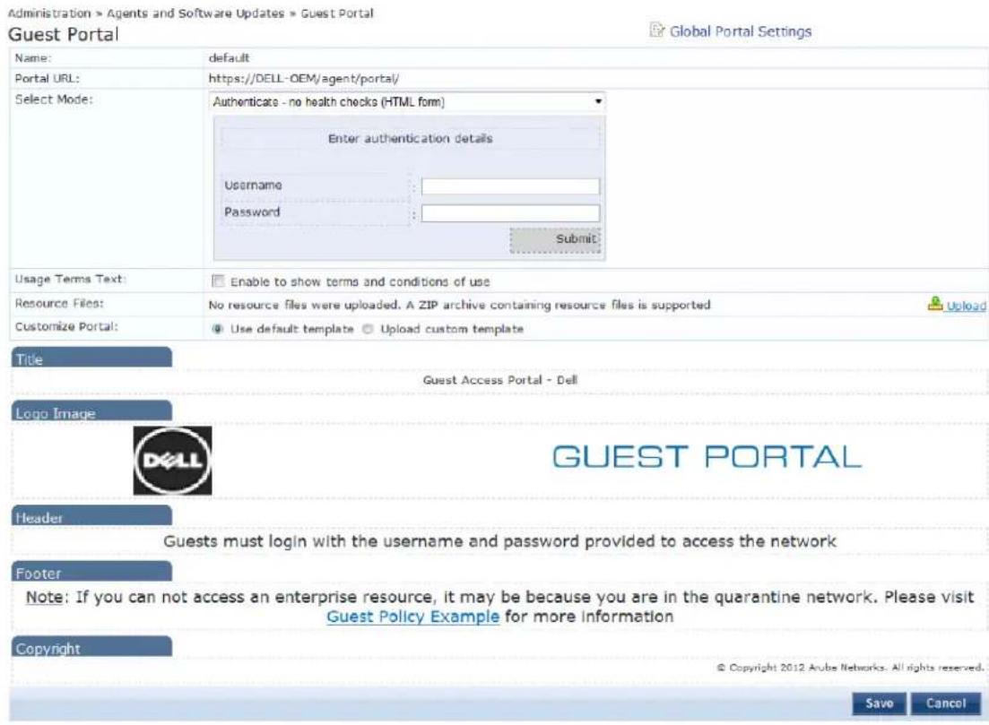
- Specify the W-ClearPass Guest Portal parameters as described in the following table, then click Save:
Table 268: W-ClearPass Guest Portal Parameters
| Parameter Action/Description | |
| Select Option Select the page that the user first sees after logging in to W-ClearPass:Default Landing PageApplication Login Page:Guest Portal | |
| Page Title Click and enter the text to appear as the page title in the default landing page. | |
| Logo Image Click and browse to select an image for the banner in the default landing page. | |
| Top section Click and enter the text to appear as the header in the default landing page. | |
| Bottom section Click and enter the text to appear as the footer in the default landing page. | |
| Copyright Click and enter the copyright text to appear in the default landing page. |

Both the HTTP and HTTPS protocols are supported for Guest Portal redirection.
Managing Admin Users
This section describes the following topics:
• Changing the Administration Password
- Adding an Admin User
- Importing and Exporting Admin Users
- Setting Password Policy for Admin Users
• Disabling Admin User Accounts
Changing the Administration Password
After activating the W-ClearPass appliance, the recommended next task is to change the administration password for the newly-activated W-ClearPass server.
To change the administration password:
- Navigate to Administration > Users and Privileges > Admin Users.
The Admin Users page opens.
Figure 474: Admin Users Page
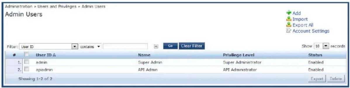
In this page, you can view the administrator details such as user ID, user name, and privilege level. You can also change the admin password, and add, import, export, and set password policies for the users by using the links provided at the top-right corner of this page.
- Select the Admin user you want to modify.
The Edit Admin User dialog opens.
Figure 475: Changing the Administration Password
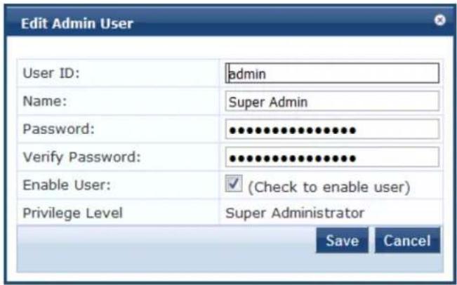
- Change the administration password, then click Save.
Adding an Admin User
To add a new admin user:
- Navigate to Administration > Users and Privileges > Admin Users.
- Click the Add link at the top-right corner the page.
The Add Admin User dialog opens.
Figure 476: Adding an Admin User
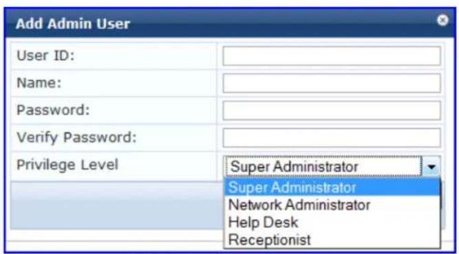
- Specify the Add Admin User parameters as described in the following table, then click Save:
Table 269: Adding an Admin User Parameters
| Parameter Action/Description | |
| User ID 1. Specify a user ID for this administrator. | |
| Name 2. Specify the name | for the admin user. |
| Password/ Verify Password | 3. Specify a password for the local user, then verify the password. |
| Enable User 4. You must enable this check box to enable the admin user account (is is enabled by default). Otherwise, the admin user account is disabled. | |
| Privilege Level 5. From the drop-down list, select one of the following admin user privilege levels:■ API Administrator■ Help Desk■ Network Administrator■ Read-only Administrator■ Receptionist■ Super Administrator | |
Importing and Exporting Admin Users
You can import or export the admin user accounts by using the Import and Export All links at the top-right corner of the Admin Users page.
You can also export specific admin user accounts by using the Export button that appears after selecting one or more admin user accounts from the list.
For more information, refer to Importing and Exporting Information on page 32.
The passwords of the admin user accounts are not stored in clear text when exported to an XML file.

Setting Password Policy for Admin Users
To set password policies for the administrators:
-
Navigate to Administration > Users and Privileges > Admin Users.
-
Click the Account Settings link at the top-right corner of the Admin Users page.
The Password Policy Settings dialog opens.
Figure 477: Admin Users > Setting Password Policy
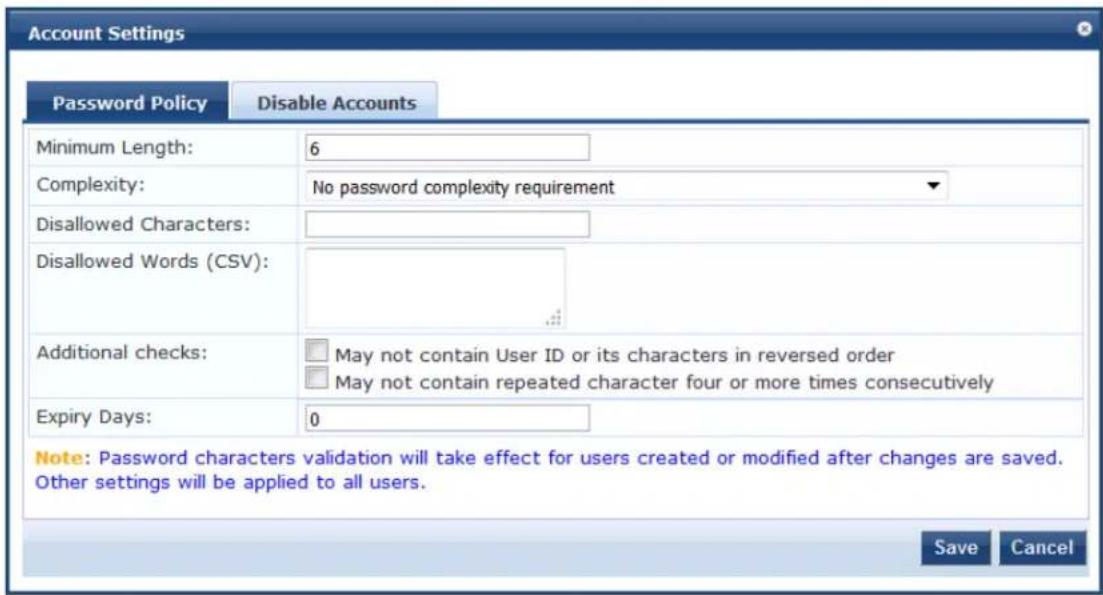
- Specify the Password Policy parameters as described in Table 270, then click Save:
Table 270: Password Policy Parameters
| Parameter Action/Description | |
| Minimum Length 1. Specify the minimum length required for the password. | |
| Complexity | 2. Select the complexity setting from the Complexity drop-down list. The complexity settings can be one of the following:■ No password complexity requirement■ At least one uppercase and one lowercase letter■ At least one digit■ At least one letter and one digit■ At least one of each: uppercase letter, lowercase letter, digit■ At least one symbol■ At least one of each: uppercase letter, lowercase letter, digit, and symbol |
| Disallowed Characters 3. Specify the characters not to be allowed in the password. | |
| Disallowed Words (CSV) | 4. Specify the words not to be allowed in the password |
| Additional Checks | 5. Select any additional checks, if required. The options are:■ May not contain User ID or its characters in reversed order.■ May not contain repeated character four or more times consecut |
| Expiry Days | 6. Set the password expiry time for the local users.The allowed range is 0 to 500 days. The default value is 0.NOTE: If the value is set to 0, the password never expires. For any other value, local users are forced to reset the expired password when they W-ClearPass alerts users five days before the password expires. |

Password Policy settings are effective only for the users created or modified after the changes are saved.
Disabling Admin User Accounts
The Admin user account can be disabled in two ways:
- When the Admin user tries to log in with an invalid password for a configured number of times defined by the Failed attempts count parameter, the Admin user account is locked.

If the mechanism for logging in to W-ClearPass Policy Manager is Certificate + Password, the Admin user is allowed to enter the password even if the certificate is invalid.
- When the Admin user tries to log in with an invalid user certificate for a configured number of times defined by the Failed attempts count parameter, the Admin user account is disabled.
- To reset the Failed attempts count and enable a disabled Admin user account, click the Reset button (see Table 271).
- For Admin users whose accounts are locked due to account settings validations, and whose accounts are enabled again after being locked out, entries are logged in both the Audit Viewer (see Audit Viewer on page 167) and the Event Viewer (see Event Viewer on page 169).
The Disable Account check occurs every day at midnight.
To specify the conditions for disabling admin user accounts:
- Navigate to Administration > Users and Privileges > Admin Users.
- Click the Account Settings link at the top-right corner of the Admin Users page.
The Account Settings page opens.
- Select the Disable Accounts tab.
The Disable Accounts dialog opens.
Figure 478: Admin Users > Disable Accounts Dialog
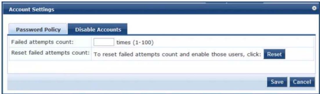
- Specify the Disable Accounts parameters as described in Table 271, then click Save.
Table 271: Admin Users > Disable Accounts Parameters
| Parameter Action/Description | |
| Failed attempts count 1. Specify the number of failed log-in attempts are allowed before the account is disabled.The range is from 1 to 100 attempts. | |
| Reset failed attempts count 2. To reset the failed attempts count to zero and reenable those admin users who were disabled after exceeding the failed attempts count, click Reset. |
Managing Admin Privileges
This section provides the following information:
Overview
• Defining Custom Admin Privileges
- Creating Custom Administrator Privileges on page 489
- Administrator Privilege XML File Structure on page 489
• Administrator Privileges and Task IDs on page 489
• Sample Administrator Privilege XML File on page 493
Overview
W-ClearPass Policy Manager ships with the following default administrator admin privileges XML files:
• API Administrator
- Help Desk
• Network Administrator
• Read-only Administrator
- Receptionist
• Super Administrator
Each of these default admin privileges administrators, define the admin privileges for Policy Manager and Insight. The default set of admin privileges cannot be modified.
You can export one or more default files and modify the file to create a customized administrator privilege file.
Customized administrator privileges are defined in an XML file with a specific format and then imported in W-ClearPass Policy Manager on the Admin Privileges page.
Defining Custom Admin Privileges
When a different set of admin privileges is needed (for example, if you require different admin privileges the Report module than the admin privileges defined for the other Insight modules), you must create a admin privileges administrator.
To define custom admin privileges for W-ClearPass and Insight:
- Navigate to the Administration > Users and Privileges > Admin Privileges page.
The Admin Privileges page opens:
Figure 479: Admin Privileges Page
Administration » Users and Privileges » Admin Privileges
Admin Privileges
Import
Export All
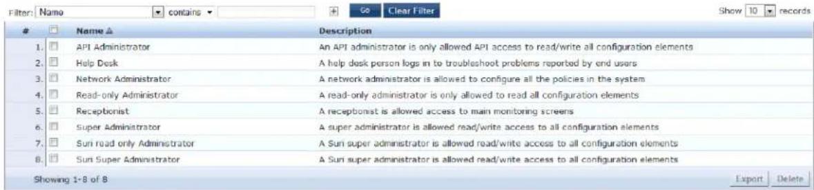
2. Click the Add link.
The Add Admin Privileges dialog opens.
Figure 480: Add Admin Privileges Page: Basic Information Tab
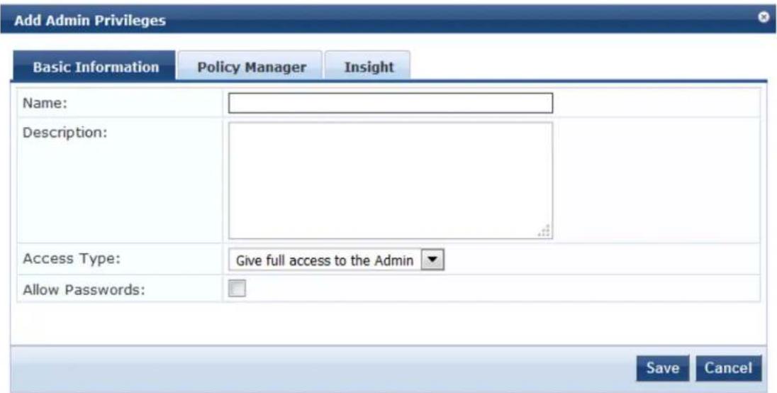
3. Specify the parameters in the Basic Information tab as described in Table 272.
Table 272: Add Admin Privileges Parameters: Basic Information Tab
| Parameter Action/Description | |
| Name 1. Enter the name of the Admin Privileges administrator. | |
| Description 2. Provide a description of this new admin privileges administrator. | |
| Access Type 3. Select one of the following Access Types:Give full access to the AdminGive UI access to the AdminGive API access to the Admin | |
| Allow Passwords 4. Select this check box if you want to allow password access. |
Configuring Policy Manager Admin Privileges
To configure the Policy Manager admin privileges:
- Select the Policy Manager tab.
The following dialog opens:
Figure 481: Specifying Policy Manager Admin Privileges
![Edit Admin Privileges General Policy Manager Insight [-] Dashboard Read Read,Write Read,Write,Delete [+] Monitoring Read Read,Write Read,Write,Delete [+] Live Monitoring Read Read,Write Read,Write,Delete [+] Profiler and Discovery Read Read,Write Read,Write,Delete Audit Viewer Read Read,Write Read,Write,Delete Event Viewer Read Read,Write Read,Write,Delete Data Filters Read Read,Write Read,Write,Delete Blacklisted Users Read Read,Write Read,Write,Delete [-] Configuration Read Read,Write Read,Write,Delete Start Here Read Read,Write Read,Write,Delete Services Read Read,Write Read,Write,Delete [+] Authentication Read Read,Write Read,Write,Delete Save Cancel](/content/2026/05/842116/images/c81d2e7492385711199ebbaf9d72743a931063f0d3753bddf7f11eb548ef9bd3.jpg)
- Specify the admin privileges for each of the W-ClearPass components, then click Save.
Configuring Insight Admin Privileges
To configure the Insight admin privileges:
- Select the Insight tab.
The following dialog opens:
Figure 482: Specifying Insight Admin Privileges

- Specify the admin privileges for each of the Insight modules, then click Save.
Creating Custom Administrator Privileges
To create a custom admin privilege XML file, you must use a plain text or XML editor.

Do not use word processing applications such as Microsoft Word, which introduce tags and corrupt the XML file.
To create a custom administrator privilege:
- Create an XML file that defines a privilege.
- Store the new file.
- Navigate to Administration > Users and Privileges > Admin Privileges.
- Click Import Admin Privileges.
- Import the administrator privilege file you created in step 1.
After you complete steps 1 through 5, the new administrator privileges document is displayed on the Admin Privileges page.
Administrator Privilege XML File Structure
Admin privilege files are XML files with a specific structure. It must have a header at the beginning of the following format:
<?xml version="1.0" encoding="UTF-8" standalone="yes"?>
The root tag is TipsContents. It is a container for the data in the XML file which must be in the following format:
<TipsContents xmlns="http://www.avendasys.com/tipsapiDefs/1.0">
</TipsContents>
An optional TipsHeader tag can follow the TipsContents tag. The actual admin privileges information is defined with the AdminPrivilege and AdminTask tags. You can use one AdminPrivilege tag for each admin privilege you want to define. The AdminPrivilege tag contains the following two attributes:
- name
- description
You can have one or more AdminTask tags inside the AdminPrivilege tag. Each AdminTask tag defines a lace within the W-ClearPass Policy Manager application that a user with that privilege can view or change AdminTask tag contains one taskid attribute and a single AdminTaskAction tag. The AdminTaskAction tag contains an attribute, type which can take a value, RO (read only) or RW (read/write).
The following sample gives the basic structure of an admin privilege file:
Administrator Privileges and Task IDs
Every element in the W-ClearPass Policy Manager user interface has a task ID associated with it.
The users have access to the elements based on the permissions set for each task or element. By default permission provided for a task is applicable for all its sub-tasks.
For example, if you give RW (read-write) permissions for the task, Enforcements (con.en), it is automatically applied to its subtasks, Policies (con.en.epo) and Profiles (con.en.epr). Hence, you need not explicitly define the same permission for those subtasks.
The following table provides the tasks and subtasks of W-ClearPass Policy Manager and their associated IDs:
Table 273: Administrator Privileges and Task IDs
| Area (W-ClearPass Policy Manager Menu) | Task ID |
| Dashboard | dnd |
| Monitoring mon | |
| Live Monitoring mon.li | |
| Access Tracker | mon.li.ad |
| Accounting | mon.li.ac |
| Onguard Activity | mon.li.ag |
| Analysis and Trending | mon.li.sp |
| Endpoint Profiles | mon.li.ep |
| System Monitor | mon.li.sy |
| Audit Viewer | mon.av |
| Blacklisted Users | mon.bl |
| Event Viewer | mon.ev |
| Data Filters | mon.df |
| Configuration | con |
| Start Here (Services Wizard) | con.sh |
| Services | con.se |
| Service Templates | con.st |
| Authentication | con.au |
| Methods | con.au.am |
| Sources | con.au.as |
| Identity | con.id |
| ■ Single Sign-On con.id.sso | |
| ■ Local Users con.id.lu | |
| ■ Endpoints con.id.ep | |
| ■ Static Host Lists con.id.sh | |
| ■ Roles con.id.rs | |
| ■ Role Mappings con.id.rm | |
| • Posture con.pv | |
| ■ Posture Policies con.pv.in | |
| ■ Posture Servers con.pv.ex | |
| ■ Audit Servers | con.pv.au |
| • Enforcements | con.en |
| ■ Policies | con.en.epo |
| ■ Profiles | con.en.epr |
| • Network | con.nw |
| ■ Devices | con.nw.nd |
| ■ Device Groups | con.nw.ng |
| ■ Proxy Targets | con.nw.pr |
| Policy Simulation | con.ps |
| Profile Settings | con.prs |
| Administration | adm |
| • User and Privileges adm.us | |
| ■ ClearPass Portal | adm.po.cp |
| ■ Admin Users | adm.us.au |
| ■ Admin Privileges | adm.us.ap |
| • Server Manager | adm.mg |
| Server Configuration adm.mg.sc | |
| Log Configuration adm.mg.ls | |
| Local Shared Folders adm.mg.sf | |
| Licensing | adm.mg.li |
| External Servers | adm.xs |
| SNMP Trap Receivers | adm.xs.st |
| Syslog Targets | adm.xs.es |
| Syslog Export Filters | adm.xs.sx |
| Messaging Setup | adm.xs.me |
| Endpoint Context Servers | adm.xs.cs |
| Context Server Actions | adm.di.csa |
| Certificates | adm.cm |
| Server Certificate | adm.cm.mc |
| Trust List | adm.cm.ctl |
| Revocation List | adm.cm.crl |
| Dictionaries | adm.di |
| RADIUS | adm.di.rd |
| Posture | adm.di.pd |
| TACACS+ Services | adm.di.td |
| Fingerprints | adm.di.df |
| Attributes | adm.di.at |
| Applications | adm.di.ad |
| Agents and Software Updates | adm.po |
| Onguard Settings | adm.po.aas |
| Software Updates | adm.po.es |
| • Support adm.su | |
| • Contact Support adm.su.cs | |
| • Remote Assistance adm.su.ra | |
| • Documentation adm.su.doc |
Sample Administrator Privilege XML File
This section provides sample XML files with different admin privileges for various user interface elements:
- Read Only (R) Privileges to All Sections
- Read/Write Access
- Read/Write Permissions
Read Only (R) Privileges to All Sections
The following sample provides Read Only (R) privileges to all the sections (dnd, con, mon, adm):
<?xml version="1.0" encoding="UTF-8" standalone="yes"?>
<TipsContents xmlns="http://www.avendasys.com/tipsapiDefs/1.0">
<TipsHeader exportTime="Thu Jul 26 17:57:50 IST 2016" version="6.6"/>
<AdminPrivileges>
    <AdminPrivilege name="Read-only Administrator" description="A read-only administrator is only allowed to read all configuration elements">
    <AdminTask taskid="con"> //Refers to Configuration
    <AdminTaskAction type="R"/>
    </AdminTask>
    <AdminTask taskid="dnd"> //Refers to Dashboard
    <AdminTaskAction type="R"/>
    </AdminTask>
    <AdminTask taskid="mon"> //Refers to Monitoring
    <AdminTaskAction type="R"/>
    </AdminTask>
    <AdminTask taskid="adm"> //Refers to Administration
    <AdminTaskAction type="R"/>
    </AdminTask>
    </AdminPrivilege>
</AdminPrivileges>
</TipsContents>
Read/Write Access
The following sample provides Read/Write access only to Guest, Local and Endpoint Repository:
<?xml version="1.0" encoding="UTF-8" standalone="yes"?>
<TipsContents xmlns="http://www.avendasys.com/tipsapiDefs/1.0">
<TipsHeader exportTime="Thu Jul 26 17:57:50 IST 2016" version="6.6"/>
<AdminPrivileges>
    <AdminPrivilege name="Read/Write Access to Guest, Local and Endpoint Repository" description="A read-only administrator is only allowed to read all configuration elements">
    <AdminTask taskid="con.id.lu"> //Refers to Local Users Section
    <AdminTaskAction type="RW"/>
    </AdminTask>
    <AdminTask taskid="con.id.gu"> //Refers to Guest Users Section
    <AdminTaskAction type="RW"/>
</AdminTask>
<AdminTask taskid="con.id.ep"> //Refers to Endpoints Section
<AdminTaskAction type="RW"/>
</AdminTask>
</AdminPrivilege>
</AdminPrivileges>
</TipsContents>
Read/Write Permissions
The following sample provides Read/Write permissions to Dashboard/ Monitoring and ReadOnly permission to Server Configuration:
<?xml version="1.0" encoding="UTF-8" standalone="yes"?>
<TipsContents xmlns="http://www.avendasys.com/tipsapiDefs/1.0">
<TipsHeader exportTime="Thu Jul 26 17:57:50 IST 2016" version="6.6"/>
<AdminPrivileges>
    <AdminPrivilege name="Limited access permission" description="A read-only administrator is only allowed to read all configuration elements">
    <AdminTask taskid="dnd"> //Refers to Dashboard
    <AdminTaskAction type="RW"/>
    </AdminTask>
    <AdminTask taskid="mon"> //Refers to Monitoring
    <AdminTaskAction type="RW"/>
    </AdminTask>
    <AdminTask taskid="adm.mg.sc"> //Refers to Server Configuration
    <AdminTaskAction type="R"/>
    </AdminTask>
    </AdminPrivilege>
</AdminPrivileges>
</TipsContents>
Server Configuration
This section describes the following server configuration tasks:
• Editing Server Configuration Settings on page 495
- Configuration Tasks for Disabled Nodes in a Cluster on page 496
- Synchronizing the Cluster Date and Time with the NTP Server on page 537
- Changing the Cluster-Wide Password on page 540
• Managing Policy Manager Zones on page 541
- Configuring NetEvents Targets on page 543
- Configuring Virtual IP Settings on page 545
- Clearing Machine Authentication Cache on page 545
• Cluster-Wide Parameters on page 547
• Making a Subscriber Node on page 546
• Collecting Logs on page 562
- Backing Up the Policy Manager Database on page 563
• Restoring Policy Manager Configuration Data on page 564
• Performing a System Cleanup on page 565
- Shutting Down or Rebooting the Server on page 566
- Dropping a Subscriber Node on page 567
You can perform numerous server configuration tasks by navigating to Administration > Server Manager > Server Configuration page in W-ClearPass Policy Manager.
Figure 483: Server Configuration Page
![Administration = Server Manager = Server Configuration Server Configuration Set Date & Time Change Cluster Password Manage Policy Manager Zones NetEvents Targets Virtual IP Settings Clear Machine Authentication Cache Make Subscriber Cluster-Wide Parameters Publisher Server: VM-6121 [10.] Server Name ▲ Management Port Data Port Zone Profile Cluster Sync Last Sync Time 1 VM-6121 10 - default Enabled Enabled - Showing 1-1 of 1 Collect Logs Backup Restore Cleanup Shutdown Roboot](/content/2026/05/842116/images/1b51197b792b306fe6cdf0b4959a8260a64dfd10dda56b5ce7faa997af85d075.jpg)
Editing Server Configuration Settings
This section provides the following information:
- Cluster-Related Options
• Modifying W-ClearPass Server Settings - Configuration Tasks for Disabled Nodes in a Cluster
To modify the configuration settings of a W-ClearPass server:
- Navigate to the Administration > Server Manager > Server Configuration page.
The Server Configuration page opens.
Figure 484: Server Configuration Page
![Administration » Server Manager » Server Configuration Server Configuration Set Date & Time Change Cluster Password Manage Policy Manager Zones NetEvents Targets Virtual IP Settings Clear Machine Authentication Cache Make Subscriber Cluster-Wide Parameters Publisher Server: VM-6121 [10.] # Server Name △ Management Port Data Port Zone Profile Cluster Sync Last Sync Time 1 VM-6121 10. default Enabled Enabled - Showing 1-1 of 1 Collect Logs Backup Restore Cleanup Shutdown Robo!](/content/2026/05/842116/images/0cea71602e0cfb5372d267e757285fa05893146a07e431ec143545770cd0a6a4.jpg)
- Click the W-ClearPass server name of interest.
The Server Configuration page for the selected server opens:
Figure 485: Server Configuration Page for the Selected Server
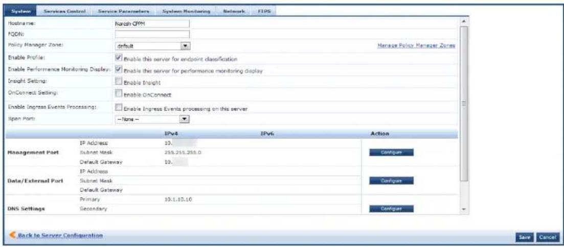
Cluster-Related Options
For details on the cluster-related options, see Server Configuration Cluster Options on page 537.
Modifying W-ClearPass Server Settings
For details on modifying W-ClearPass server settings, refer to the following sections:
• System Page on page 499
• Services Control Page on page 507
• Service Parameters Page on page 508
• System Monitoring Page on page 523
• Network Page on page 525
• FIPS Page on page 534
Configuration Tasks for Disabled Nodes in a Cluster
You can perform the following configuration tasks only for disabled nodes in a cluster:
• Synchronizing the Cluster Password
- Promoting a W-ClearPass Subscriber Node to Publisher
- Joining a W-ClearPass Server Back to the Cluster
Figure 486: Server Configuration Page with Disabled Nodes

Publisher Server: vm-69 [10.17.5.69]

For more information on the Service Configuration, see Server Configuration on page 494.
Synchronizing the Cluster Password
Use the Synchronize Cluster Password link to synchronize the password of the selected node with cluster.
Synchronizing the cluster password will change the appadmin password for all the nodes in the cluster.
The following figure displays the Synchronize Cluster Password with Publisher dialog:
Figure 487: Synchronize Cluster Password with Publisher Dialog
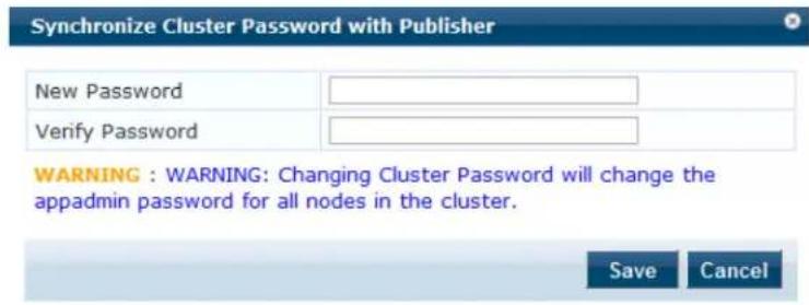
Promoting a W-ClearPass Subscriber Node to Publisher
Use the Promote To Publisher link to promote the selected node as a Publisher node. You can enable this node as a Publisher node using any other active node that is part of the same cluster.
All application licenses will be deactivated; you need to contact Dell Support to reactivate these licenses. following figure displays the Promote to Publisher window:
Figure 488: Promote Node to Publisher
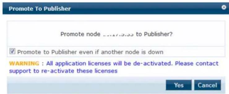
Joining a W-ClearPass Server Back to the Cluster
Use the Join server back to cluster link to join a W-ClearPass server back to the cluster.
You can use this option only for a server that is in the Cluster Sync > Disabled state.

Only users with Admin access can join a W-ClearPass node back to a cluster.
To join a server back to the cluster:
- Select a Subscriber node that is in Disabled state.
The Server Configuration > System tab opens.
Figure 489: Server Configuration > Join Server Back to Cluster Link
Administration > Server Manager > Server Configuration - vm-69 Server Configuration - vm-69 (10....)
Set Time Zone
Y Synchronize Cluster Password
Promote To Publisher
Join server back to cluster
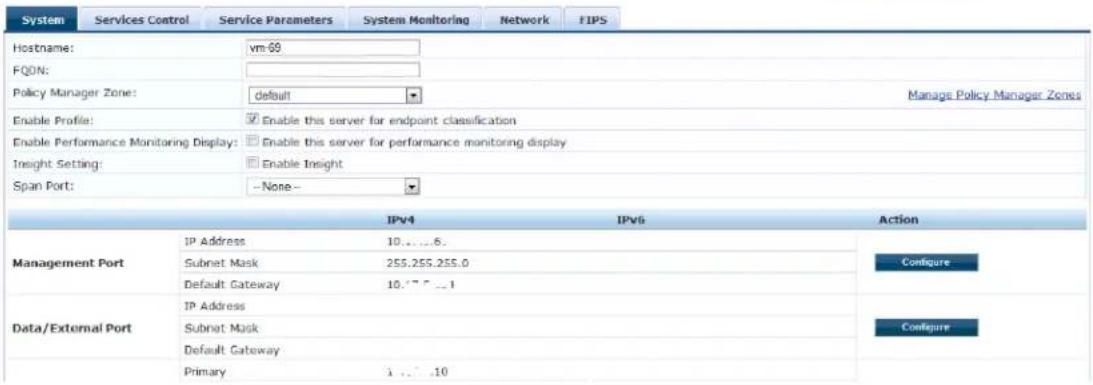
- Click the Join server back to cluster link at the top-right corner.
A warning message appears with a prompt to promote the node to Publisher. This option can only be triggered from a node that is currently active in the cluster. The following message displays the warning message:
Figure 490: Join Server Back to Cluster Confirmation Dialog
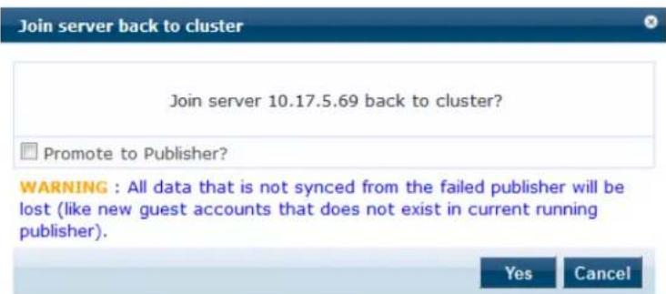
- Click Yes.
A progress indicator shows the progress of the operation.
The following figure displays the Join server back to cluster progress indicator:
Figure 491: Join Server Back to Cluster Progress Window
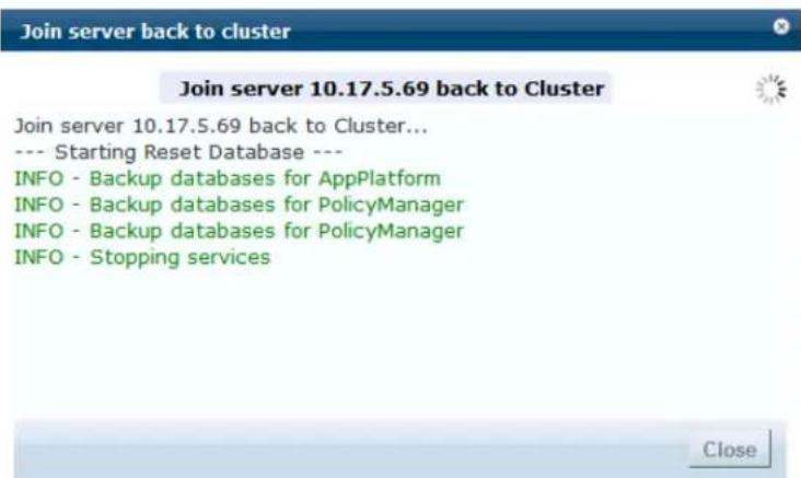
- For a failed Publisher node, the following message will be displayed in the Dashboard page:
Figure 492: Publisher Warning Message
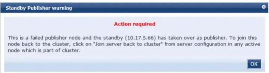
System Page
The Server Configuration page opens onto the System page (see Figure 493).
Figure 493: Server Configuration > System Page
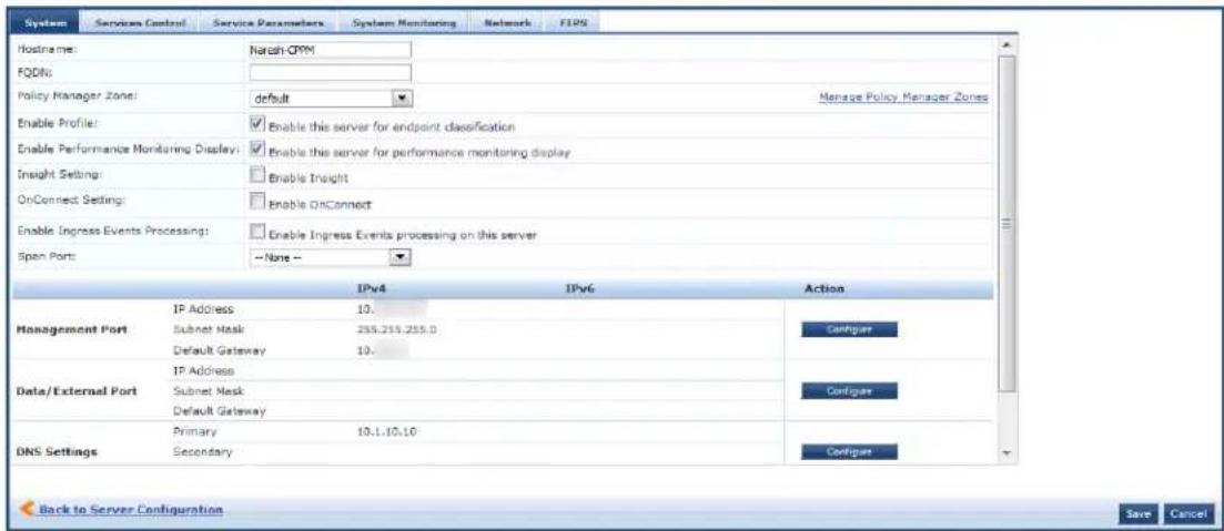
- Specify the Server Configuration > System page parameters as described in the following table, then click Save:
Table 274: Server Configuration > System Page Parameters
| Parameter Action/Description | |
| Hostname 1. Specify the host name of the Policy Manager server.NOTE: You do not need to enter the fully qualified domain name in this field. | |
| FQDN 2. Enter the Fully-Qualified Domain Name (FQDN) of the Policy Manager server. | |
| Policy Manager Zone 3. To add or delete zones, select a previously configured zone from the drop-down then click the Manage Policy Manager Zones link.For more information on adding or deleting zones, see Adding Policy Manager Zones. | |
| Enable Profile | 4. To enable the Policy Manager server to perform endpoint classifications, select the Enable Profile check box. |
| Enable Performance Monitoring | 5. To enable the W-ClearPass Policy Manager server to perform performance monitoring, select the Enable Performance Monitoring check box. |
| Insight Setting | 6. To enable the Insight reporting tool on this node, select the Enable Insight check box.NOTE:When you enable this check box for Insight on a node in a cluster, the [Insight Repository] configuration is updated automatically to point to the management IP address of that server.When this check box is enabled for other servers in the cluster, they are added as backups for the same authentication source.The order of the primary and backup servers in the [Insight Repository] is the same order in which the user enables Insight on the server. |
| Enable as Insight Master | 7. To specify the current server in the cluster as an Insight Master, select this check box.NOTE: This option is available only when Insight Setting > Enable Insight is enabled. |
| OnConnect Setting | 8. To enable the OnConnect Enforcement on this node, select the Enable OnConnect check box.When you enable OnConnect, a drop-down box appears that allows you to specify whether the selected server is the Primary or Secondary master for agentless OnConnect Enforcement in its zone.NOTE: When you enable the Enable OnConnect check box, you must specify the current W-ClearPass server as a Primary or Secondary Master for OnConnect Enforcement.9. From the drop-down list, select Primary master or Secondary master.The first server that is enabled for OnConnect Enforcement in a zone is automatically designated as the Primary master for that zone. After other servers in the zone are enabled for OnConnect Enforcement, if the Primary master fails, the designated Secondary master takes over until the Primary master is back on-line.For information on creating an OnConnect Enforcement service, see W-ClearPass OnConnect Enforcement Service on page 100.NOTE: In order for OnConnect Enforcement to be fully functional, OnConnect must be enabled both the W-ClearPass server and on any network devices that you wish to use for OnConnect Enforcement (see Enabling W-ClearPass OnConnect Enforcement on a Network Device on page 470).NOTE: During OnConnect, the domain name and machine name are fetched, along with the logged-in user name. The domain name can be used as an attribute for enforcement policies. |
| Enable Ingress Events Processing | 10. Check this check box to enable ingress events processing on this server.For more information, see Configuring Processing for Ingress Events. |
| Enable as Insight Master | 11. To specify the current server in a cluster as an Insight Master, select this check box.NOTE: This option is available only when Insight Setting > Enable Insight is enabled. |
| Span Port | 12. If necessary, select a port for DHCP spanning.On selecting a port, the Enable TCP/ARP Fingerprinting check box appears.This field is optional. |
| Enable TCP/ARP Fingerprinting | 13. To enable TCP/ARP fingerprinting, select the EnableTCP/ARPFingerprintingcheck box.This feature allows the Netbridge service to capture TCP and ARP packets and the derived inputs to the Device Profiler.NOTE: This option appears only when you specify aSpan Port. |
| Management Port | 14. To configure the Management Port parameters, clickConfigure.The Configure Management Portdialog opens. For details, see Management Port Configuration on page 501. |
| Data/External Port 15. | To configure the Data/External port, clickConfigure.For details, see Data/External Port Configuration on page 502. |
| DNS Settings 16. To configure the DNS settings, clickConfigure.For details, seeDNS SettingsConfiguration on page 502. | |
| AD Domains Displays a list of the joined Active Directory domains.17. To join an active directory domain, clickJoin Domain.For details on joining an AD domain, see Join AD Domain Configuration on page 503. | |
Management Port Configuration
To configure the W-ClearPass server's Management port:
- From the Administration > Server Manager > Server Configuration > System > Management Port section, click Configure.
The Configure Management Port dialog opens.
Figure 494: Configure Management Port Dialog
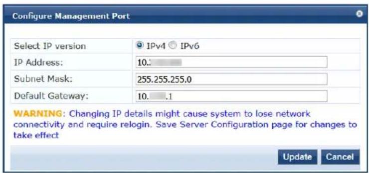
- Select IP Version: Select the IP version—IPv4 or IPv6.
- IP Address: Specify the IP address (IPv4 or IPv6) to access the W-ClearPass Policy Manager.
- Subnet Mask: Specify the management interface subnet mask for an IPv4 address.
IPv6 addresses do not require a netmask as they use Classless Inter-Domain Routing (CIDR). - Default Gateway: Specify the default gateway for the management interface.
- Click Update.
Data/External Port Configuration
To configure the W-ClearPass server's Data/External port:
- From the Server Configuration > System > Data/External Port section, click Configure. The Configure Data/External Port dialog opens.
Figure 495: Configure Data/External Port Dialog
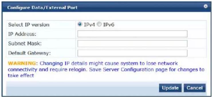
- Select IP Version: Select the IP version—IPv4 or IPv6.
- IP Address: Specify the IP address (IPv4 or IPv6) of the W-ClearPass server's data interface.
- Subnet Mask: Specify the data interface subnet mask for an IPv4 address.
IPv6 addresses do not require a netmask as they use Classless Inter-Domain Routing (CIDR). - Default Gateway: Specify the default gateway for the data interface.
- Click Update.
DNS Settings Configuration
To configure the W-ClearPass server's Data/External port:
- From the Server Configuration page > System tab > DNS Settings, click Configure. The Configure DNS Setting dialog opens.
Figure 496: Configure DNS Settings Dialog
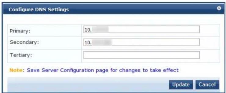
- Primary: Specify the primary DNS server for name look-up.
A DNS server can be primary for one domain and secondary for another. Only one DNS server should be configured as primary for a domain, but you can have any number of secondary DNS servers.
- Secondary: Specify one or more secondary DNS servers for name look-up.
The recommended practice is to configure the primary and secondary DNS servers on separate machines, on separate Internet connections, and in separate geographic locations.


- Tertiary: Optionally, in the rare event of both the primary and secondary DNS servers going down, you can configure a tertiary DNS server.
- Click Update.
Join AD Domain Configuration
To join the selected W-ClearPass server to an Active Directory domain:
- From the Server Configuration page > System tab > AD Domains, click Join AD Domain. The Join AD Domain dialog opens.
Figure 497: Join AD Domain Dialog
![Join AD Domain Enter the FQDN of the controller and the short (NETBIOS) name for the domain: Domain Controller NetBIOS Name In case of a controller name conflict Use specified Domain Controller Use Domain Controller returned by DNS query Fail on conflict ✓ Use default domain admin user [Administrator] Username Password Save Cancel](/content/2026/05/842116/images/2987499b790797e8c25caf14c08e736f7676161c4dd4eb2b51806c4a1a974e52.jpg)
- Domain Controller: Enter the Fully Qualified Domain Name (FQDN) of the domain controller, then press Tab.
The following message is displayed: Trying to determine the NetBIOS name...
W-ClearPass searches for the NetBIOS name for the domain.
NetBIOS is another term for the short domain name, or the NT4 domain name, also known as the pre-Windows 20 domain name.
If W-ClearPass determines the NetBIOS name, the NetBIOS Name field is automatically populated.
- In case of a controller name conflict:
a. Use specified Domain Controller: Accept the default setting.
b. Use default domain admin user [Administrator]: Accept the default setting.
In a production environment, it is likely that an Administrative username that has permissions to join machines to the domain would be used for the default domain admin user. In that case, 1) disable (that is, uncheck) the Use default domain admin user [Administrator] check box and 2) enter the Administrative username and password in the fields provided.
c. Password: Enter the password for the user account that will join W-ClearPass with the domain, then click Save.
Table 275 displays the characters that are allowed and not allowed for the Active Directory username and password:


Table 275: Characters Allowed and Not Allowed for Active Directory Username and Password
| Field Characters Allowed Not Allowed | ||
| Username | ~!@#%^*_-+=,.\'"?/ | `&() |
| Password | !@#%^&*( )_-+={{<,>.?/ | ~`[]\|;:'" |
The Join AD Domain status screen opens. The screen displays the message "Adding host to AD domain," and the screen displays status during the joining process.
When the joining process completes successfully, you see the message "Added host to the domain."
4. Click Close.
You return to the Server Configuration page, and it now shows that the W-ClearPass server is joined to the domain.
Now that the W-ClearPass Policy Manager server has joined the domain, the server can authenticate users with Active Directory.
After an Active Directory Domain is added, the domain controller can be setup as a password server. For more information on adding a password server, see Adding a Password Server on page 506.
Join AD Domain
You can join W-ClearPass Policy Manager to an Active Directory (AD) domain to authenticate users and computers that are members of an Active Directory domain. If you join W-ClearPass to an Active Directory domain, it creates an account for the W-ClearPass node in the Active Directory database.
Users can then authenticate into the network using 802.1X and EAP methods, such as PEAP-MSCHAPv2, with their own their own Active Directory credentials.
If you need to authenticate users belonging to multiple Active Directory forests or domains in your network, and there is no trust relationship between these entities, then you must join W-ClearPass to each of these untrusted forests or domains.
W-ClearPass does not require to join multiple domains belonging to the same Active Directory forest because a one-way trust relationship exists between those domains. In this case, W-ClearPass can join the root domain.
W-ClearPass can join or leave an Active Directory domain by using the following two buttons in the Server Configuration page > System tab:
- Join Domain: Click Join Domain to join this W-ClearPass appliance to an Active Directory domain. Password servers can be configured after Policy Manager is successfully joined. For more information on adding a password server, see Adding a Password Server on page 506.
- Leave Domain: If the server is already part of multiple Active Directory domains, click Leave Domain to disassociate this W-ClearPass appliance from an Active Directory domain.
For most use cases, if you have multiple nodes in the cluster, you must join each node to the same Active Directory domain.


The following figure displays the Join AD Domain dialog:
Figure 498: Join AD Domain Dialog
![Join AD Domain Enter the FQDN of the controller and the short (NETBIOS) name for the domain: Domain Controller AMG-AD.LOCADOMAIN.COM NetBIOS Name AMG-AD In case of a controller name conflict Use specified Domain Controller Use Domain Controller returned by DNS query Fail on conflict Use default domain admin user [Administrator] Username Password Save Cancel](/content/2026/05/842116/images/29fbfe56e221aa0bb5eb58449245e72a6a0a7e9de3d9442474950ad30663f95c.jpg)
Specify the Join AD Domain parameters as described in the following table.
Table 276: Join AD Domain Parameters
| Parameter Action/Description | |
| Domain Controller | Enter the fully qualified name of the Active Directory domain controller. |
| NETBIOS name (optional) | Enter the NetBIOS name of the domain.Enter this value only if this is different from your regular Active Directory domain name, different from your domain name (usually a shorter name), enter that name here. Conta Active Directory administrator about the NetBIOS name.NOTE: If you enter an incorrect value for the NetBIOS name, you see a warning messag user interface. If you see this warning message, leave the domain by clicking on theLea Domain button (which replaces theJoin Domainbutton once you join the domain). After leaving the domain, join again with the correct NetBIOS name. |
| Domain Controller name conflict | Specify the action to take in the event of a domain controller name conflict.In some deployments (especially if there are multiple domain controllers, or if the doma has been wrongly entered in the last step), the domain controller FQDN returned by the query can be different from what was entered. In this case, you can:Use specified Domain Controller: Continue to use the domain controller name that you entered.Use Domain Controller returned by DNS query: Use the domain controller name returned by the DNS query.Fail on conflict: Abort the Join Domain operation. |
| Use default domain admin user | Check this box to use the Administrator user name to join the domain |
| Username Enter | the user ID of the domain administrator account.This field is disabled if the Use default domain admin user check box is selected. |
| Password Enter | the password of the domain administrator account. |
Adding a Password Server
After W-ClearPass successfully joins an Active Directory domain, you can configure a restricted list of don controllers to be used for MSCHAP authentication. If this is not configured, then all available domain controllers obtained from DNS will be included.
To add a password server:
- In the AD Domains section of the System tab, click the Add Password Server icon 📋. This icon appears only after W-ClearPass joins at least one Active Directory domain (see Figure 499).
Figure 499: Add Password Server icon

The Configure AD Password Servers page opens.
- Specify the domain name, NetBIOS Name, and the password servers.
The password servers can be a hostname or an IP address. Use a new line for each entry.
- Click Save to complete adding the password servers.
The following figure displays the Configure AD Password Servers dialog with the password servers added to the configuration:
Figure 500: Active Directory Password Server Added
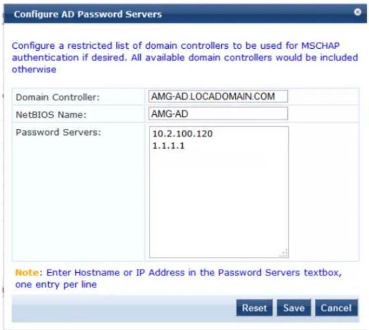
Services Control Page
From the Services Control page, you can:
• View the status of all the services: Running or Stopped.
- Stop or start Policy Manager services, including any Active Directory domains that the server joins.
The following figure displays the Services Control page:
Figure 501: Services Control Page
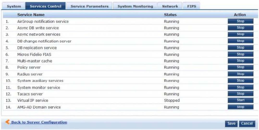
Service Parameters Page
Navigate to the Administration > Server Manager > Server Configuration > Service Parameters page to change system parameters of the services listed below.
This section describes the following topics:
• Async Network Services Options on page 508
• W-ClearPass IPsec Service on page 509
• W-ClearPass Network Services Options on page 510
• W-ClearPass System Services Options on page 513
• Ingress Logger Service Ports on page 516
• Policy Server Options on page 517
• RADIUS Server Options on page 518
• Stats Collection Service Options on page 521
• System Monitor Service Options on page 522
• TACACS Server Options on page 523
The following figure displays the Service Parameters page:
Figure 502: Service Parameters Page
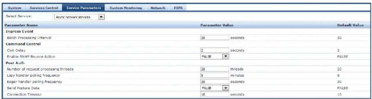
Async Network Services Options
Configure the Ingress Event, Command Control, and Post-Auth parameters for the Async network service.
The following figure displays the Service Parameters > Async network services parameters:
Figure 503: Async Network Services
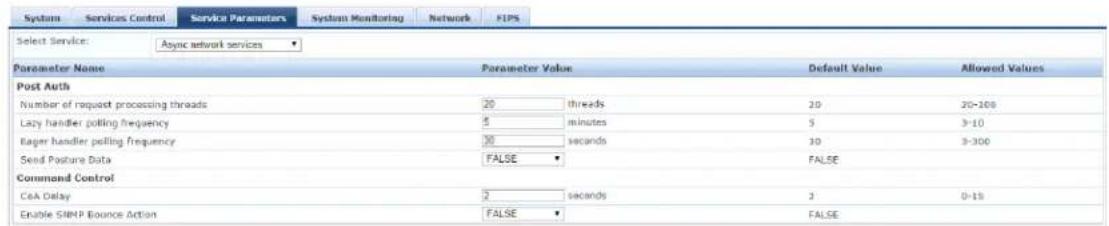
Table 277: Service Parameters >Async Network Services
| Parameter Action/Description | |
| Ingress Event | |
| Batch Processing Interval | Specify the batch processing interval for ingress event processing.The default interval is 30 seconds. The range of values is 10 to 300 seconds.NOTE: For changes to the Batch Processing Interval to take effect, you must restart theAsync Network service. |
| Post Auth | |
| Number of request processing threads | Set the number of request processing threads.The default value is 20 threads, and the range of values is between 20 and 100. |
| Lazy handler polling frequency | Set theLazy handler polling frequency (in minutes).The default value is 5 minutes, and the allowed values are from 3 to 10 minutes.Lazy handler polling is employed when an attribute may not require to be updated unless it explicitly asks for it. When it is required, even if there is no available fresh value, it can be fetched by initiating a separate request. |
| Eager handler polling frequency | Set theEager handler polling frequency (in seconds).The default value is 30 seconds, and the allowed values are from 10 to 300 seconds.Eager handler polling is employed when an attribute requires the freshest possible value. |
| Send Posture Data To send posture data to the Palo Alto Firewall server, set this toTRUE. | |
| Command Control | |
| CoA Delay Set the CoA Delay value (in seconds).The default value is 2, and the allowed values are from 0 to 15 seconds. | |
| Enable SNMP Bounce Action | Set the Enable SNMP Bounce Action value.The default value isFALSE. |
W-ClearPass IPsec Service
When a network device requests an IPsec connection between the device and a W-ClearPass server, W-ClearPass uses the Online Certificate Status Protocol (OCSP) URI (uniform resource identifier) specified in Figure 504 to contact a third-party server that checks to see if the certificate sent by the requesting device is valid.
If the certificate is confirmed as valid, an IPsec connection between the W-ClearPass server and the required network device is established.
To configure the W-ClearPass IPsec service:
- Navigate to Administration > Server Manager > Server Configuration, then select the W-ClearPass server.
-
Select the Service Parameters tab.
-
From the Select Service drop-down, select W-ClearPass IPsec service.
The following dialog opens:
Figure 504: W-ClearPass IPsec Service Dialog
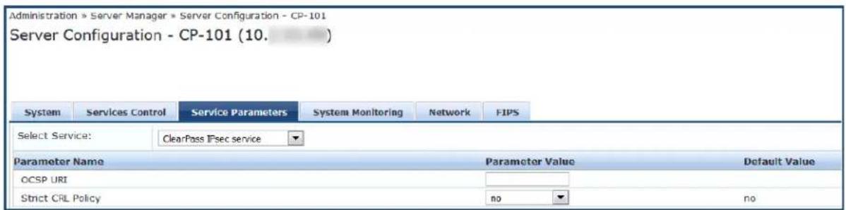
- Specify the Service Parameters > W-ClearPass IPsec Service parameters as described in Table 278, then click Save.
Table 278: Service Parameters > W-ClearPass IPsec Service Parameters
| Parameter Action/Description | |
| OCSP URI | In the Parameter Value field, specify the HTTP or HTTPS URI (uniform resource identifier) for the Online Certificate Status Protocol (OCSP).OCSP enables the W-ClearPass server to determine the revocation state of a certificate presented by a peer—for example a network device requesting an connection to the W-ClearPass server.NOTE:When you enter the OSCP URI, W-ClearPass checks that 1) the URI is proper format (it must start with HTTP or HTTPS and be syntactically correct), and 2) W-ClearPass checks to see if the specified OSCP server IP address or host is reachable from the W-ClearPass node. A descriptive error message will be displayed in the event of an incorrect OSCP URI. |
| Strict CRL Policy You can | enable or disable a strict Certificate Revocation List (CRL) policy. This parameter is disabled by default.To enable Strict CRL Policy, select Yes from the Parameter Value drop-down.When this option is enabled, a fresh Certificate Revocation List must be available in order for a peer connection to succeed.Whenever Strict CRL Policy is modified, existing IPsec tunnels that use Public Key Authentication are brought down and then brought up again. |
W-ClearPass Network Services Options
The W-ClearPass Network Services parameters aggregate service parameters from the following services:
SNMP Service
• Certificate Authentication Service
• Web Authentication Service
• Posture Service
• DHCP Snooper Service
The following figure displays the Service Parameters tab > W-ClearPass Network Services parameters (partial view):
Figure 505: Service Parameters > W-ClearPass Network Services
| System Services Control Service Parameters System Monitoring Network FIPS | ||||
| Select Service: ClearPass network services | ||||
| Parameter Name Parameter Value Default Value Allowed Values | ||||
| DhcpSnooper | ||||
| MAC to IP Request Hold time | 120 seconds 120 60-300 | |||
| DHCP Request Probation Time | 30 seconds 30 10-60 | |||
| SmpService | ||||
| SNMP Timeout | 4 seconds 4 2-30 | |||
| SNMP Retries | 1 retries 1 1-5 | |||
| LinkUp Timeout | 5 seconds 5 3-15 | |||
| IP Address Cache Timeout | 600 seconds 600 12-1200 | |||
| Uplink Port Detection Threshold | 5 5 0-20 | |||
| SNMP v2c Trap Community | ●●●●● public | |||
| SNMP v3 Trap Username | aruba aruba | |||
| SNMP v3 Trap Authentication Protocol | ||||
| SNMP v3 Trap Privacy Protocol | ||||
| SNMP v3 Trap Authentication Key | ||||
| SNMP v3 Trap Privacy Key | ||||
| Device Info Poll Interval | 60 minutes 60 10-1500 | |||
| WebAuthService | ||||
| Max time to determine network device where client is connected | 0 seconds 0 0-100 | |||
| PostureService | ||||
| Audit Thread Pool Size | 20 threads 20 5-40 | |||
| Audit Result Cache Timeout | 600 seconds 600 1-864000 | |||
| Audit Host Ping Timeout | 60 seconds 60 1-300 | |||
The following figure displays the Service Parameters tab > W-ClearPass Network Services parameters in FIPS mode:
Figure 506: Service Parameters > W-ClearPass Network Services in FIPS Mode
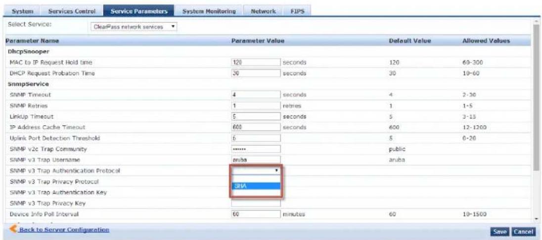
Specify the W-ClearPass Network Services parameters as described in the following table:
Table 279: Service Parameters > W-ClearPass Network Services
| Service Parameters | Action/Description |
| SnmpService | |
| SNMP Timeout Specify | the seconds to wait for an SNMP response from the network device. |
| SNMP Retries Specify | the number of retries for SNMP requests. |
| LinkUp Timeout Specify | the seconds to wait before processing link-up traps.If a MAC notification trap arrives in this time, the SNMP service does not try to switch for MAC addresses behind a port for link-up processing. |
| IP Address Cache Timeout | Specify the duration in seconds for which MAC-to-IP lookup response is cached. |
| Uplink Port Detection Threshold | Specify the limit for the number of MAC addresses found behind a port after which port is considered an uplink port and not considered for SNMP lookup and enforce The default value is 5, with a range from 0 to 20. |
| SNMP v2c Trap Community | Specify the community string that must be checked in all incoming SNMP v2 traps |
| SNMP v3 Trap Username | Specify the SNMP v3 Username to be used for all incoming traps. |
| SNMP v3 Trap Authentication Protocol | Specify the SNMP v3 Authentication protocol for traps.The options are: MD5, SHA, or empty (to disable authentication).NOTE: The EAP-MD5 authentication type is not supported if you use W-ClearPass Policy Manager in FIPS mode. |
| SNMP v3 Trap Privacy Protocol | Specify the SNMP v3 Privacy protocol for traps.The options are: DES_CBC, AES_128, or empty (to disable privacy).NOTE: The DES_CBC privacy protocol is not supported if you use W-ClearPass Policy Manager in FIPS mode. |
| SNMP v3 Trap Authentication Key | Specify the SNMP v3 authentication key and privacy key for incoming traps. |
| SNMP v3 Trap Privacy Key | |
| Device Info Poll Interval | Specify the time (in minutes) between polling for device information. |
| Certificate Auth | |
| OCSP Check | Specify one of the following options for initiating an Online Certificate Status Protocol (OCSP) check:None(the default setting)OptionalRequired |
| WebAuthService | |
| Max time to determine network device where client is connected | Specifies the maximum time to wait for Policy Manager to determine the network to which the client is connected.In some usage scenarios where the web authentication request does not originate the network device, Policy Manager has to determine the network device to which client is connected through an out-of-band SNMP mechanism. The network device deduction process can take some time. |
| PostureService | |
| Audit Thread Pool Size | Specify the number of threads to use for connections to audit servers. |
| Audit Result Cache Timeout | Specify the time (in seconds) for which audit result entries are cached by Policy Manager. |
| Audit Host Ping Timeout | Specify the number of seconds for which Policy Manager pings an end-host before giving up and deeming the host to be unreachable. |
| DhcpSnooper | |
| MAC to IP Request Hold time | Specify the number of seconds to wait before responding to a query to get an IP address corresponding to a MAC address.Any DHCP message received in this time period refreshes the MAC address-to-IP address binding.Typically, an audit service requests a MAC-to-IP mapping as soon the RADIUS request is received, but the client may take some more time to receive the IP address through DHCP. This wait period takes into account the latest DHCP IP address that the client received. |
| DHCP Request Probation Time | Specify the number of seconds to wait before considering the MAC-to-IP binding received in a DHCPREQUEST message as final.This wait handles cases where a client receives a DHCPNAK for a DHCPREQUEST and receives a new IP address after going through the DHCPDISCOVER process again. |
W-ClearPass System Services Options
You can use the W-ClearPass system service parameters for PHP configuration and for HTTP traffic flow in through a proxy server.
W-ClearPass Policy Manager relies on an HTTP connection for the W-ClearPass Update Portal to download latest information for system services.
The following figure displays the Service Parameters > W-ClearPass System Services parameters (partial view):
Figure 507: W-ClearPass System Services Parameters
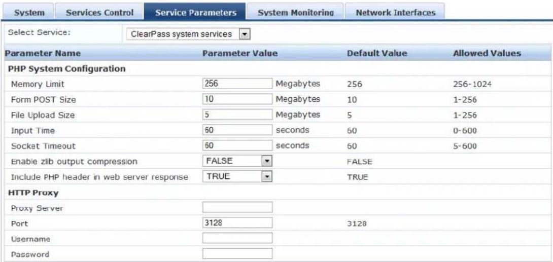
Specify the Service Parameters > W-ClearPass System Services parameters as described in the following table.
Table 280: Service Parameters > W-ClearPass System Services
| Service Parameter Action/Description | |
| PHP System Configuration | |
| Memory Limit Specify the maximum memory that can be used by the PHP applications. | |
| Form POST Size Specify the maximum HTTP POST content size that can be sent to the PHP application. | |
| File Upload Size Specify the maximum file size that can be uploaded into the PHP application. | |
| Input Time Specify the time limit after which the server will detect no activity from the user and will take some action. | |
| Socket Timeout | Specify the maximum time for any socket connections. |
| Enable zlib output compression | Specify the setting to compress the output files. |
| Include PHP header in web server response | Specify the setting to include PHP header in the HTTP responses. |
| HTTP Proxy | |
| Proxy Server | Specify the hostname or IP address of the proxy server. |
| Port Specify the port at which the proxy server listens for HTTP traffic. | |
| Username Specify the user name to authenticate with the proxy server. | |
| Password Specify the password to authenticate with the proxy server. | |
| Database Configuration | |
| Maximum connections | Specify a number between 300 and 2000 for a maximum number of allowed connections. |
| TCP Keepalive Configurations | |
| Keep Alive Time Specify a value in seconds from 10 to 86400. | |
| Keep Alive Interval Specify a value in seconds from 1 to 3600. | |
| Keep Alive Probes Specify a value from 1 to 100 for the number of probes. | |
| Web Server Configuration | |
| Maximum Clients | Specify a value from 10 to 20000 for the maximum number of clients allowed. |
| Timeout | Specify a server timeout value in seconds from 1 to 60. |
| Keep Alive | To enable or disable keep-alive for the web server, select TRUE or FALSE. |
| Request Wait | Specify the request wait time in seconds from 1 to 60. The default value is 4 seconds. |
| Maximum Requests Specify a number between 0 and 3000 for the maximum number of requests allowed. The default value is500. | |
| Enable Host Header check | Specify whether to enable the host header check.The default value isTRUE.When you set this value toTRUE, the Host Header Restriction checkis enabled and only the allowed or whitelisted host headers are allowed.When you set this value toFALSE, irrespective of Host Headers in the http packet, W-ClearPass Policy Manager redirects tohttps:///tips. |
| WhiteList Host Names | When theEnable Host Header checkvalue is set toTRUE, the web access is allowed for Whitelist Host Names, hostnames, IP addresses, and VIP addresses in W-ClearPass Policy Manager. The comma separated whitelist host names are allowed to support multiple hostnames.When theEnable Host Header checkvalue is set toTRUEand the WhiteList Host Namesfield is blank, the web access is allowed only for hostnames, IP addresses, and VIP addresses in W-ClearPass Policy Manager. |
Ingress Logger Service Ports
When Ingress Event Processing is enabled and configured on W-ClearPass (see Configuring Processing for Ingress Events on page 731), logging of ingress events occurs automatically.
By default, the W-ClearPass server listens for Ingress Events on TCP port 514 and UDP port 514.
If necessary, you can change these Syslog Ingress Logger ports.
To change the Syslog Ingress Logger ports:
- Navigate to Administration > Server Manager > Server Configuration, then select the W-ClearPass server.
- Select the Service Parameters tab.
- From the Select Service drop-down, select Ingress Logger Service.
The following dialog opens:
Figure 508: Ingress Logger Service Dialog
| System | Services Control | Service Parameters | System Monitoring | Network | FIPS | |
| Select Service: | Ingress logger service | |||||
| Parameter Name | Parameter Value | Default Value | Allowed Values | |||
| Syslog Configuration | ||||||
| TCP Port | 514 | 514 | 1-65535 | |||
| UDP Port | 514 | 514 | 1-65535 | |||
- To change the Ingress Logger TCP Port, enter the new port number in the Parameter Value field.
- To change the Ingress Logger UDP Port, enter the new port number.
- Click Save.
Policy Server Options
The following figure displays the Service Parameters > Policy Server dialog:
Figure 509: Policy Server Service Parameters
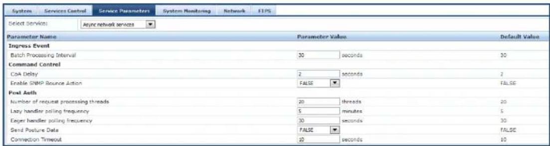
Specify the Service Parameters > Policy Server parameters.
Table 281: Service Parameters > Policy Server Service
| Service Parameter Action/Description | |
| Machine Authentication Cache Timeout | 1. Specify the time (in hours) for which machine authentication entries are cached by W-ClearPass Policy Manager.The default is 24 hours. |
| LDAP Primary Retry Interval | After a primary LDAP server is down, the W-ClearPass server connects to one of the backup servers.2. Specify how long the W-ClearPass server waits (in seconds) before it tries to connect to the primary server again. |
| Audit SPT Default Timeout | 3. Specify the time (in seconds) for which an Audit success or error response is cached in the Policy server. |
| Additional time before session deletion from multi-master cache | 4. Specify the number of seconds the Policy server will wait before deleting the multi-master entry.The default value is 0.This parameter handles roaming scenarios where an Accounting-Start occurs without an authentication request. If the value for this parameter is 0, the Policy server deletes the multi-master entry when an Accounting-Stop is received.The RADIUS server updates the multi-master entry with attribute values from the accounting request. These can be used in the Change of Authorization (CoA). In a roaming scenario, this NAS information update from the accounting request helps W-ClearPass send the CoA to the correct NAS. |
| Number of request processing threads | 5. Specify the maximum number of threads used to process requests. |
| HTTP Thread Pool Size 6. | Specify the number of threads allotted for the HTTP thread pool. |
| Authentication Thread Pool Size | 7. Specify the number of threads to use for LDAP/AD and SQL connections. |
| 8. Click Save. | |
RADIUS Server Options
The following figure displays the Service Parameters tab > RADIUS Server parameters (partial list):
Figure 510: RADIUS Server Parameters Dialog
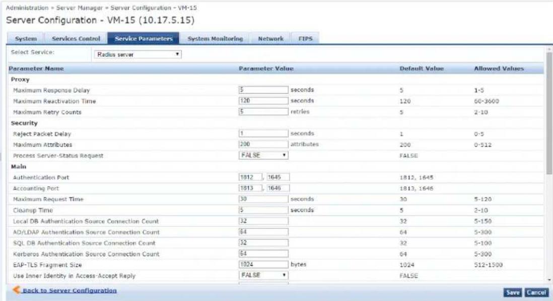
Specify the Service Parameters > RADIUS server parameters as described in the following table:
Table 282: Service Parameters > RADIUS Server Service
| Service Parameter Action/Description | |
| EAP-FAST | |
| Master Key Expire Time Specify the lifetime of a generated EAP-FAST master key. | |
| Master Key Grace Time Specify the grace period for an EAP-FAST master key after its lifetime expires.The default is 3 weeks.If a client presents a PAC (Protected Access Credential) that is encrypted using the master key in this period after its TTL (Time-to-Live), it is accepted and a new PAC encrypted with the latest master key is provisioned on the client. | |
| PACs are valid across cluster | If PACs (Protected Access Credentials) generated by this server are valid across the cluster, set to TRUE (the default setting).If not, select FALSE. |
| Proxy | |
| Maximum Response Delay If | the target server has not responded, specify the time delay before retrying a proxy request. The default is 5 seconds. |
| Maximum Reactivation Time | Specify the time to elapse before retrying a dead proxy server. |
| Maximum Retry Counts | If the target server doesn't respond, specify the maximum number of times to retry a proxy request. |
| Accounting | |
| Log Accounting Interim- Update Packets | To store the Interim-Update packets in session logs, selectTRUE. FALSEis the default setting. |
| Thread Pool | |
| Maximum Number of Threads | Specify the maximum number of threads in the RADIUS server thread pool to process requests. |
| Number of Initial Threads | Specify the initial number of threads in the RADIUS server thread pool to process requests. |
| Active Directory Errors | |
| Window Size Enter a duration during which Active Directory errors are accumulated for possible action. The default is5 minutes. | |
| Number of Errors Enter a number to specify the number of Active Directory errors that can occur within the defined Window Size and have the self-healing Recovery Action taken. The default is150. | |
| Recovery Action Select one of the following recovery actions from the drop-down list:None: To initiate no self-recovery action. This is the default.Exit: To restart the RADIUS server. (The monitoring daemon will restart it.)Restart Domain Service: To restart the Domain service. | |
| Security | |
| Reject Packet Delay Specify the delay time before sending an actual RADIUS Access-Reject message after the server decides to reject the request. | |
| Maximum Attributes Specify the maximum number of RADIUS attributes allowed in a request. The default is200. | |
| Process Server-Status Request | TRUE: Send replies to Status-Server RADIUS packets.FALSE: Do not send replies to Status-Server RADIUS packets. This is the default setting. |
| Main | |
| Authentication Port | Specify the ports on which the RADIUS server listens for authentication requests. Default values are ports1645and1812.NOTE: You can configure the Authentication Port to different values if desired. |
| Accounting Port Specify the | ports on which the RADIUS server listens for accounting requests.The default values are 1646 and 1813.NOTE: You can configure the Accounting Port to different values if desired. |
| Maximum Request Time Specify the maximum time (in seconds) allowed for processing a request after which it is considered timed out. The default is 30 seconds. | |
| Cleanup Time Specify the time to cache the response sent to a RADIUS request after sending it.The range is from 2 to 10 seconds. The default is 5 seconds.If the RADIUS server gets a duplicate request for which the response is a sent, and the duplicate request arrives within this time period, the cached response is resent. | |
| Local DB Authentication Source Connection Count | Specify the maximum number of Local DB connections opened. |
| AD/LDAP Authentication Source Connection Count | Specify the maximum number of Active Directory and LDAP (Lightweight Directory Access Protocol) connections opened.The range is from 5 to 300. The default is 64. |
| SQL DB Authentication Source Connection Count | Specify the maximum number of SQL DB. |
| Kerberos Authentication Source Connection Count | Specify the maximum number of Kerberos connections opened. |
| EAP-TLS Fragment Size Specify the maximum allowed size (in bytes) for the EAP-TLS fragment. | |
| Use Inner Identity in Access- Accept Reply | To use the inner identity in the Access-Accept replies, select TRUE. FALSE is the default setting. |
| Reject if OCSP response does not have Nonce | To reject an OCSP response without a nonce, select TRUE. Else, select FALSE. |
| Include Nonce in OCSP request | Specify one of the following:TRUE: Select if the OCSP (Online Certificate Status Protocol) request should include the nonce. This is the default value.FALSE: To avoid the EAP-TLS authentication failure, select if the OCSP server does not support the nonce. |
| Enable signing for OCSP Request | To enable signing for OCSP request, select TRUE.This determines whether W-ClearPass should sign an OCSP request with a RADIUS server certificate. The default value is FALSE. |
| Check the validity of all | To check the validity of all certificates in the chain against Certificate Revocation |
| certificates in the chain against CRLs | Lists (CRLs), selectTRUE. Else, selectFALSE. |
| ECDH Curve Select one of the following ECDH curve (Elliptic Curve Diffie-Helman) options from the drop-down list:X9.62/SECG curve over a 256-bit prime fieldNIST/SECG curve over a 384-bit prime field | |
| Disable TLS 1.2 To disable Transport Layer Security 1.2 (TLS 1.2), selectTRUEREVSEis the default setting—TLS 1.2 is enabled by default. | |
| Check the validity of intermediary certificates in the chain using OCSP | To check the validity of intermediary certificates in the chain using OCSP, eTRUE.The defaOnline Certificate Status Protocol isFALSE. |
| Maximum Number of AD Authentication Processes | To specify the maximum number of Active Directory authentication process enter a number between 1 and 5.The default is 1. |
| Verify OCSP Signing Purpose | Specify one of the following:TRUE:EAP-TLS authentication will fail unless the OCSP signing certificate also has the OCSP signing purpose set.FALSE:The OCSP signing certificate does not need to have the OCSP signing purpose set. This is default setting. |
| TLS Session Cache Limit Specify the number of TLS sessions to cache before purging the cache (used in TLS based 802.1X EAP Methods).The range is from1,000to100,000. The default is10,000. | |
Stats Collection Service Options
The following figure displays the Service Parameters tab > Stats Collection Service parameters:
Figure 511: Stats Collection Service Parameters
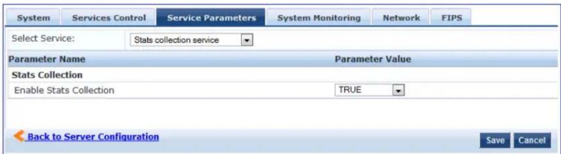
The following table describes the Service Parameters tab > Stats Collection Service parameter:
Table 283: Service Parameters > Stats Collection Service
| Service Parameter | Action/Description |
| Enable Stats Collection | Enable or disable statistics collection and aggregation.The Statistics Collection Service is enabled by default (TRUE).If this is not enabled, statistics collection and aggregation services will not run on the nodeIn addition, if statistics collection and aggregation is not enabled, the following error messa displayed if the admin attempts to start these services:Failed to start Stats collection service - Ignoring service start request as Stats Collect option is disabled on the nodeNOTE: Enabling or disabling this parameter requires a restart of the cpass-statsd-server and cpass-carbon-server. |
System Monitor Service Options
The following figure displays the Service Parameters tab > System Monitor Service parameters:
Figure 512: System Monitor Service Parameters
| System | Services Control | Service Parameters | System Monitoring | Network Interfaces |
| Select Service: | System monitor service | |||
| Parameter Name | Parameter Value | Default Value | ||
| Free Disk Space Threshold | 30 % | 30 | ||
| 1 Min CPU load average Threshold | 3 % | 3 | ||
| 5 Min CPU load average Threshold | 2 % | 2 | ||
| 15 Min CPU load average Threshold | 1 % | 1 | ||
The following table describes the Service Parameters tab > System Monitor Service parameters:
Table 284: Services Parameters > System Monitor Service
| Service Parameter | Action/Description |
| Free Disk Space Threshold | This parameter monitors the available disk space on the current W-ClearPass server node. Specify the Free Disk Space Threshold (the default is 30%). If the available disk free space falls below the specified threshold, the W-ClearPass server sends SNMP traps to the configured trap servers. |
| 1 Min CPU load average Threshold | These parameters monitor the CPU load average of the system, specifying thresholds for 1-minute, 5-minute, and 15-minute averages, respectively. If any of these loads exceed the associated maximum value, the W-ClearPass server sends traps to the configured trap servers. |
| 5 Min CPU load average Threshold | |
| 15 Min CPU load average Threshold |
TACACS Server Options
The Service Parameters >TACACS Server dialog provides two parameters:
• TACACS+ Profiles Cache Timeout
• TACACS+ HTTP Thread Pool Size
Figure 513: Service Parameters > TACACS+ Server Dialog

Specify the Service Parameters > TACACS server parameters as described in the following table:
Table 285: Service Parameters > TACACS Server
| Service Parameter | Action/Description |
| TACACS+ProfilesCacheTimeout | Specify the time (in seconds) for which TACACS+ profile result entries are cached by W-ClearPass Policy Manager. |
| TACACS+ HTTP Thread Pool Size | Specify the maximum number of simultaneous requests the server can handle.The default value is 100.The range is from 5 to 200.When the server has reached the limit or request threads, it defers processing new requests until the number of active requests drops below the specified amount.Increasing this value reduces HTTP response latency times. |
System Monitoring Page
By configuring the System Monitoring parameters, you can ensure that the external Management Information Base (MIB) browsers can browse the system-level MIB objects exposed by the W-ClearPass P0 Manager appliance. The options in this page vary based on the SNMP version that you select.
To configure the System Monitoring parameters:
- Navigate to the Administration > Server Manager > Server Configuration page.
- Select the W-ClearPass server of interest.
- Select the System Monitoring tab.
The System Monitoring configuration dialog opens:
Figure 514: System Monitoring Configuration Dialog
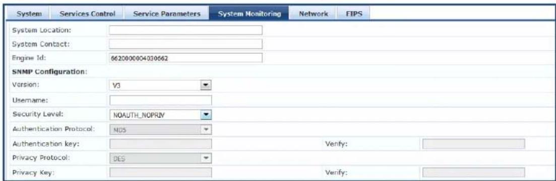
- Specify the System Monitoring configuration parameters as described in the following table:
Table 286: System Monitoring Parameters
| Parameter Action/Description | |
| System Location Specify the location of the W-ClearPass Policy Manager appliance. | |
| System Contact Specify the contact information of the W-ClearPass Policy Manager appliance. | |
| Engine ID A unique identifier for the SNMP v3 agent. The engine ID is used with a hashing function to generate keys for authentication and encryption of SNMP v3 messages.The default value for the Engine ID is 6620000004030662.The Engine ID is automatically generated when you enable the stand-alone SNMP agent. | |
| SNMP Configuration | |
| Version | Specify the SNMP version from the options V1, V2C, or V3.The SNMP parameters on this page vary based on the SNMP version selected. |
| Community String | V1 and V2C: Enter and reenter the community string for sending traps. This is applicable only for SNMP V1 and V2C versions. |
| Username | V3 only: Specify the user name to use for SNMP v3 communication. |
| Security Level | V3 only: Select any of the following options:NOAUTH_NOPRIV (No authentication or privacy): When you select this security level, only the SHA authentication protocol is available.AUTH_NOPRIV (Authentication but no privacy): When you select this security level, the MD5 and SHA authentication protocols are available.AUTH_PRIV (Authenticate and keep the communication private): When you select this security level, the MD5 and SHA authentication protocols are available. |
| Authentication Protocol | V3 only: Select the authentication protocol from MD5 or SHA.These protocols vary depending on the security level that you selected in the Security Level field.NOTE: The MD5 authentication protocol is not supported in FIPS mode. |
| Authentication key | V3 only: Enter and reenter the authentication key. This field is available only if you selected V3 as the SNMP version in the Version field. |
| Privacy Protocol | V3 only: Select the privacy protocol from DES or AES. |
| Privacy Key | V3 only: Enter the privacy key. |
Network Page
This section provides the following information:
• Defining Application Access Control Restrictions
- Adding an SSH Public Key
- Creating GRE Tunnels
- Creating IPsec Tunnels
- Creating VLANs
To configure the Server Configuration > Network parameters:
- Navigate to Administration > Server Manager > Server Configuration.
- Select the W-ClearPass server of interest.
- Select the Network tab.
The Server Configuration > Network page opens:
Figure 515: Server Configuration > Network Page
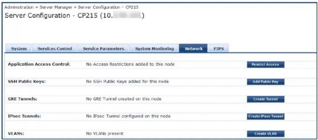
Defining Application Access Control Restrictions
Use this function to define specific network resources and allow or deny them access to specific applicat You can create multiple definitions.
To configure network application access control restrictions:
- Navigate to the Administration > Server Manager > Server Configuration.
- Select the W-ClearPass server of interest.
- From the Server Configuration page, select the Network tab.
The Server Configuration > Network page opens.
- From the Application Access Control option, click Restrict Access.
The Restrict Access dialog opens.
Figure 516: Restrict Access Configuration Dialog
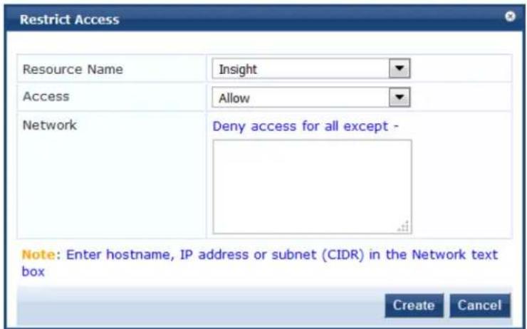
- Specify the Restrict Access parameters as described in the following table, then click Create:
Table 287: Restrict Access Parameters
| Parameter | Action/Description |
| Resource Name | Select the application to which you want to allow or deny access:OnGuardW-ClearPass APIPolicy ManagerGraphiteGuest OperatorInsight |
| Access Select | one of the access control options:Allow: Allows access to the selected application.Deny: Denies access to the selected application. |
| Network Enter | one or more host names, IP addresses, or IP subnets (CIDR) per line.The devices defined by what you enter here will be either specifically allowed or specifically access to the application you select. |
Adding an SSH Public Key
W-ClearPass supports public key-based SSH logins. This includes public key management and the ability to enable public key authentication in W-ClearPass on a node-by-node basis.
When you add the SSH public key to the clients, W-ClearPass allows passwordless SSH public key-based authentication to the appadmin W-ClearPass console.
SSH public key-based authentication will continue to work even when the cluster password or the appadmin password have been changed.
To add an SSH public key:

- Navigate to Administration > Server Manager > Server Configuration.
The Server Configuration page opens.
- Select the W-ClearPass server for which passwordless SSH is needed.
The Server Configuration dialog for the selected server opens.
- Select the Network tab.
The Server Configuration >Network page opens.
- From the SSH Public Keys option, click Add Public Key.
The Add Public Key configuration page opens.
Figure 517: Adding a Public Key
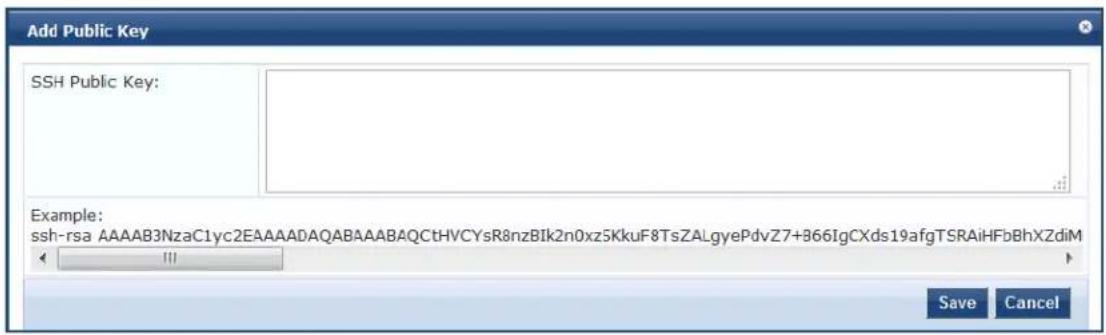
- In the SSH Public Key window, copy and paste the SSH public key of the client, then click Save.
If the SSH public key is regenerated on the client, passwordless public key-based SSH authentication will cease to work. The existing entry for that client must be deleted. Then copy and paste the new SSH public key.
- From the Server Configuration page, click Save.
The SSH operation to the W-ClearPass server using a public key is now active, and you can perform passwordless SSH to the W-ClearPass server appadmin console.
Creating GRE Tunnels
You can use the Generic Routing Encapsulation (GRE) protocol to create a virtual point-to-point link over standard IP network or the Internet.
To create a GRE tunnel:
-
Navigate to the Administration > Server Manager > Server Configuration.
-
Select the W-ClearPass server of interest.
-
From the Server Configuration page, select the Network tab.
The Server Configuration > Network page opens.
- From the GRE Tunnels option, click Create Tunnel.
The Create Tunnel dialog opens:

Figure 518: Creating a GRE Tunnel
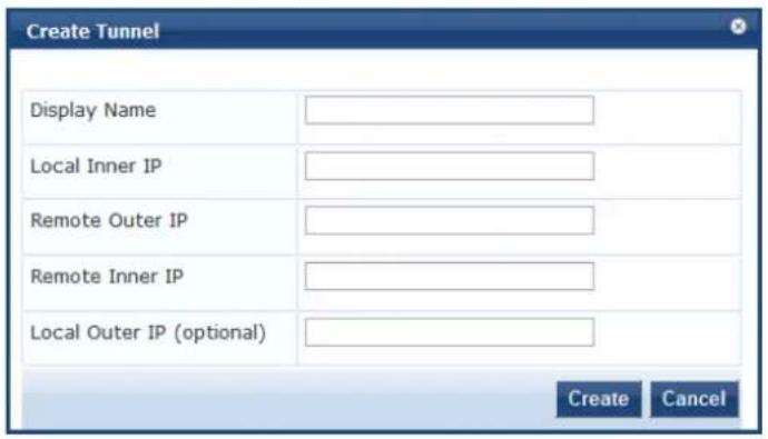
- Specify the Create Tunnel parameters as described in the following table, then click Create:
Table 288: Create Tunnel Parameters
| Parameter Action/Description | |
| Display Name Specify the name for the tunnel interface.This name is used to identify the tunnel in the list of network interfaces. | |
| Local Inner IP Enter the local IP address of the tunnel network interface. | |
| Remote Outer IP Enter the IP address of the remote tunnel endpoint. | |
| Remote Inner IP Enter the remote IP address of the tunnel network interface.Enter a value to automatically create a route to this address through the tunnel. | |
| Local Outer IP(Optional) | Optionally, enter the local IP address of the tunnel endpoint. |
Creating IPsec Tunnels
W-ClearPass provides the option to configure rules that can determine which IPsec traffic to tunnel, which traffic to drop, and which traffic to encrypt or bypass (see Figure 520).
Thus, W-ClearPass supports adding traffic selectors based on port number and protocol (TCP/UDP) with r options Bypass, Encrypt, and Drop (see Table 290).
To create an IPsec tunnel:
-
Navigate to the Administration > Server Manager > Server Configuration.
-
Select the W-ClearPass server of interest.
-
From the Server Configuration page, select the Network tab.
The Server Manager > Configuration > Network page opens.
- Click Create IPsec Tunnel.
The Create IPsec Tunnel dialog opens to the General tab.
Figure 519: Creating an IPsec Tunnel Dialog
![Create IPsec Tunnel General Traffic Selectors Local Interface 10. [MGMT] Remote IP Address 10. IPsec Mode Tunnel IKE Version 1 IKE Phase1 Mode Main Encryption Algorithm AES128 Hash Algorithm HMAC SHA Diffie Hellman Group Group 5 Authentication Type Certificate IKE Lifetime 180 minutes Lifetime 60 minutes Peer Certificate Subject DN C=US, ST=California, L=Sunnyvale, O Enabled ✓ Create Cancel](/content/2026/05/842116/images/37e5cf73bfaaf668c2b8a0f99432913315b6759f5b0632c8bf1e8731834b1afc.jpg)
- Specify the Create IPsec Tunnel parameters as described in the following table, then click Create:
Table 289: Create IPSec Tunnel Parameters
| Parameter Action/Description | |
| Local Interface Specify the local Management interface. | |
| Remote IP Address Specify the IP address of the remote host. | |
| IPsec Mode Select one of the following IPsec modes:■ Tunnel■ Transport | |
| IKE Version | Select the version of the Internet Key Exchange (IKE) protocol from the options: 1 or 2. |
| IKE Phase 1 Mode | This parameter is enabled when you select IKE Version 1. IKE Phase 1 Mode is set by default to Main. |
| PRF | The PRF (pseudorandom function) parameter is enabled when you select IKE Version 2.Select one of the following PRF options:■ PRF-HMAC-SHA1■ PRF-HMAC-SHA256■ PRF-HMAC-SHA384■ PRF-HMAC-MD5 |
| Encryption Algorithm | Select one of the following encryption algorithms:■ AES128■ AES256 |
| Hash Algorithm Select one | of the following hash algorithms:■ HMAC SHA■ HMAC-SHA256■ HMAC-SHA384■ HMAC-MD5 |
| Diffie Hellman Group Select | one of the following Diffie Hellman groups:■ Group 5■ Group 14■ Group 19■ Group 20 |
| Authentication Type Select | one of the following authentication types:■ Pre-Shared Key■ Certificate |
| IKE Shared SecretVerify IKE Shared Secret | Enter the IKE secret key, then verify the secret key. |
| IKE Lifetime Specify the number of minutes for the lifetime of the IKE. The default is 180 minutes. | |
| Lifetime | Specify the lifetime of the IPsec tunnel in minutes. The default is 60 minutes. |
| Peer Certificate Subject DN | When the authentication type is set to Certificate, you can configure the Peer Subject Certificate DN (Distinguished Name) field, which ensures that the IPs connection will be successfully established only for peers that have certificates match the peer certificate subject DN.NOTE: Configuring Peer Certificate Subject DN is optional. If it is configured, Distinguished Name should match with the peer certificate DN in order to co the authentication. |
| Enabled | To enable the IPsec tunnel, click the Enabled check box. |
Traffic Selectors
A traffic selector (also known as a proxy ID in IKEv1) is an agreement between IKE peers to permit traffic through a tunnel if the traffic matches a specified pair of local and remote addresses. Only traffic that conforms to a traffic selector is permitted through the associated IPsec security association (SA).
Traffic selectors are retained after a system restart, a service restart of network services, and a service r the IPsec service.
To configure the traffic selectors for this IPsec tunnel:
- From the Create IPsec Tunnel dialog, select the Traffic Selectors tab.
The Traffic Selectors dialog opens.
Figure 520: Create IPsec Tunnel > Traffic Selectors Dialog

- Specify the Traffic Selectors parameters as described in the following table, then click Create.
Table 290: Create IPSec Tunnel > Traffic Selectors Parameters
| Parameter Action/Description | |
| Encrypt Rules Displays the | IPsec tunnel encryption rules configured for this IPsec tunnel. |
| Bypass Rules Displays the | IPsec tunnel bypass rules configured for this IPsec tunnel. |
| Drop Rules Displays the | IPsec tunnel drop rules configured for this IPsec tunnel. |
| Type Select one of the following traffic selector types:■ Bypass■ Encrypt■ Drop | |
| Protocol Select one of the | following protocols:■ Any■ TCP■ UDP |
| Port From the Port drop-down list, select the port. | |
| Reset | To reset the configuration settings to the defaults, click Reset. |
| Save Rule | To save the current Rule configuration, click Save Rule. |
Checking IPsec Tunnel Status
To check the status of an IPsec tunnel:
- Navigate to the Server Manager > Configuration > Network page.
The IPsec Tunnels section displays the configuration summary for each configured IPsec tunnel, along with an Action button to provide each IPsec tunnel's current status.
Figure 521: IPsec Tunnel Summary and Action Button to See Tunnel Status
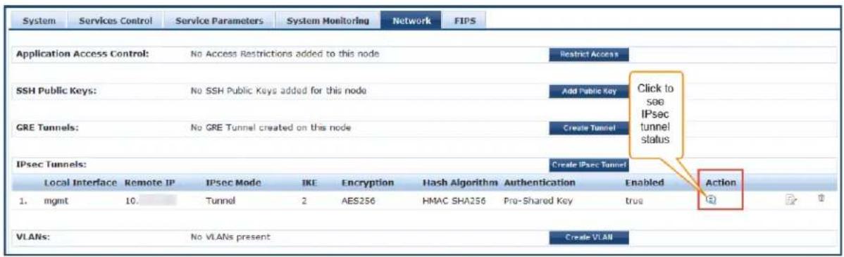
- To see the current status for an IPsec tunnel, click the Action button (see Figure 521).
The IPsec Tunnel Status window for the selected tunnel opens:
Figure 522: IPsec Tunnel Status
![IPsec Tunnel Status Remote IP Address 10. Messages Security Associations (1 up, 0 connecting): ipsec-3002[27]: ESTABLISHED 105 seconds ago, 10. .[10. .]...10. 1[10. ] ipsec-3002[27]: IKEv2 SPIs: ed2b6427b8973622_i* 29cfb2f1582e1078_r, pre-shared key reauthentication in 44 minutes ipsec-3002[27]: IKE proposal: AES_CBC_256/HMAC_SHA2_256_128/PRF_HMAC_SHA2_256 /MODP_2048 Bring Up Bring Down Cancel](/content/2026/05/842116/images/5ad4c04de795aa87a2272b493cb153539534909949ab93aa735740f881a9db3b.jpg)
■ Bring Up
If the tunnel is down, Bring Up brings up the IPsec tunnel. If you select Bring Up when the tunnel is up, W-ClearPass creates a new tunnel.
■ Bring Down
If the tunnel is up, Bring Down tears down the IPsec tunnel.
If you select Bring Down when the tunnel is down (for example, when the tunnel is still negotiating), W-ClearPass stops the tunnel from forming.
Understanding the IPsec Tunnel Status Information
A way to quickly decipher the IPsec tunnel status information is as follows:
• If the tunnel status shows ESTABLISHED, only IKE Phase 1 is complete.
• If the tunnel status shows INSTALLED, Rekeying, IKE Phase 2 is complete.
Example 1
If tunnel status shows as shown in Figure 523, Phase 1 is complete but Phase 2 is failing. Look at the Audit Viewer events (Monitoring > Audit Viewer) to find the root cause.
Figure 523: IPsec Tunnel Status: Only IKE Phase 1 Complete
Security Associations (1 up, 0 connecting):
ipsec-3001[21]: ESTABLISHED 2 minutes ago, 10. 1[10.: ...10. [10 ]
ipsec-3001[21]: IKEv2 SPIs: 601f3be10351483c_i* d033dd3590e120ff_r, pre-shared key reauthentication in 45 minutes
ipsec-3001[21]: IKE proposal: AES_CBC_256/HMAC_SHA2_256_128/PRF_HMAC_SHA2_256/MODP_2048
Shunted Connections:
ipsec-bypass-3001-1: 10.: /32 === 10. ./32[udp/syslog] PASS
Shunted Connections:
ipsec-bypass-3001-2: 10.: /32[udp/syslog] === 10. ./32 PASS
Example 2
When the tunnel status displays the information as shown in Figure 524, Phase 2 is also complete.
Figure 524: IPsec Tunnel Status: IKE Phase 1 and Phase 2 Complete
Security Associations (1 up, 0 connecting):
ipsec-3001[24]: ESTABLISHED 10 seconds ago, 10.    1[10.    1]...10.    L[10.    ]
ipsec-3001[24]: IKEv2 SPIs: 032a75ba9e13b408_i 0bc85e45e5d7de2c_r*, pre-shared key reauthentication in 2 hours
ipsec-3001[24]: IKE proposal: AES_CBC_256/HMAC_SHA2_256_128/PRF_HMAC_SHA2_256/MODP_2048
ipsec-3001{20}: INSTALLED, TUNNEL, ESP SPIs: c53510b1_i cb34ca38_o
ipsec-3001{20}: AES_CBC_256/HMAC_SHA2_256_128, 0 bytes_i, 0 bytes_o, rekeying in 44 minutes
ipsec-3001{20}: 10.    /32 === 10.    /32
Creating VLANs
To create VLAN interfaces:
- Navigate to the Administration > Server Manager > Server Configuration.
- Select the W-ClearPass server of interest.
- From the Server Configuration page, select the Network tab.
The Server Configuration > Network page opens. - From the VLANS option, click Create VLAN.
The Create VLAN dialog opens:
Figure 525: Creating a VLAN
![Create VLAN Physical Interface 10. [MGMT] VLAN Name VLAN ID IP Address Netmask Create Cancel](/content/2026/05/842116/images/e1df2aa67136237c860645961af07ec949a0e9e6c61dd304128bd7f7b076a9b1.jpg)
- Specify the Create VLAN parameters as described in the following table, then click Create:
Table 291: Server Configuration > Create VLAN Parameters
| Parameter | Action/Description |
| Physical Interface | Enter the physical port on which to create the VLAN interface.This is the interface through which the VLAN traffic will be routed.NOTE: Make sure your network supports tagged 802.1Q packets on the selected physical interface. |
| VLAN Name | Enter the name for the VLAN interface.This name is used to identify the VLAN in the list of network interfaces. |
| VLAN ID Specify the 802.1Q VLAN identifier. Enter a value between 1 and 4094.The VLAN ID cannot be changed after the VLAN interface has been created.NOTE: VLAN ID 1 is often reserved for use by network management componentsAvoid using this VLAN ID unless you know it will not conflict with a VLAN already in your network. | |
| IP Address Enter the IP address of the VLAN. | |
| Netmask | Enter the netmask for the VLAN. |
FIPS Page
This section provides information on using W-ClearPass Policy Manager in Federal Information Processing Standards (FIPS) 140-2 approved mode.
The U. S. Government developed FIPS 140-2 to define procedures, architectures, cryptographic algorithms, and other security techniques for use in government applications and networks that use cryptography.
When running in FIPS Approved mode, W-ClearPass Policy Manager utilizes a FIPS 140-2 validated cryptographic module. Support is not available for non-approved authentication methods such as EAP-MD and MD5 digest algorithms.
For details on the Validated FIPS 140-1 and FIPS 140-2 Cryptographic Modules, see:
http://csrc.nist.gov/groups/STM/cmvp/documents/140-1/140val-all.htm#2577
Enabling FIPS Mode Using CLI
You can enable FIPS mode in W-ClearPass during installation using the CLI or post-installation using the UI.
The following figure displays the prompt to enable FIPS mode using the CLI:
Figure 526: Enabling FIPS Mode
![10) Cyprus 27) Lebanon 44) Tajikistan 11) East Timor 28) Macau 45) Thailand 12) Georgia 29) Malaysia 46) Turkmenistan 13) Hong Kong 30) Mongolia 47) United Arab Emirates 14) India 31) Myanmar (Burma) 48) Uzbekistan 15) Indonesia 32) Nepal 49) Vietnam 16) Iran 33) Oman 50) Yemen 17) Iraq 34) Pakistan #? 14 The following information has been given: India Therefore TimeZone='Asia/Kolkata' will be used. Local time is now: Wed May 14 19:33:41 IST 2014. Universal Time is now: Wed May 14 14:03:41 UTC 2014. Is the above information OK? 1) Yes 2) No #? 1 Do you want to enable FIPS Mode? [yin]: _](/content/2026/05/842116/images/4dcb4d9e261c5ee96d33426e8f4e10e88dd57d176ea05d2f288a61bd52912919.jpg)
After enabling FIPS mode using the CLI commands, you can verify whether FIPS mode is enabled or not Configuration Summary page.
Figure 527: FIPS Mode > Configuration Summary
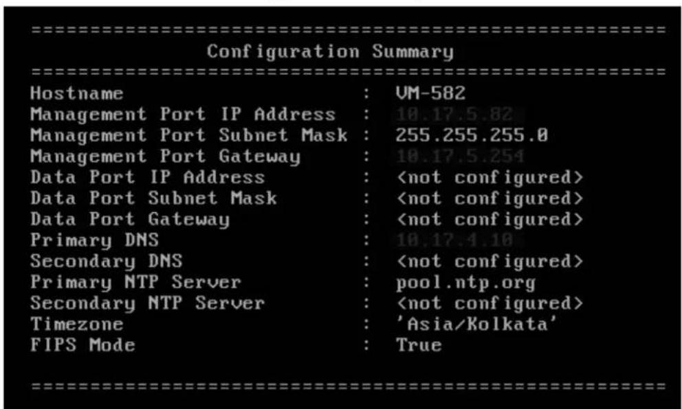
Enabling FIPS Mode in the W-ClearPass User Interface
Alternatively, you can enable or disable the FIPS mode in the W-ClearPass user interface:
- Navigate to Administration > Server Manager > Server Configuration.
-
From the Server Configuration page, select the server of interest.
The Server Configuration dialog for the selected server opens. -
Select the FIPS tab.
Figure 528: Server Configuration > FIPS Tab
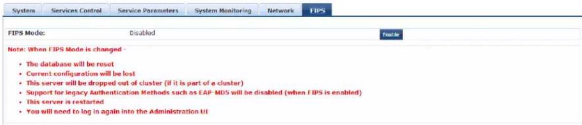
Important Points to Remember
Note the following important points, when you enable FIPS mode in the W-ClearPass Policy Manager use interface:
- The database is reset when you enable the FIPS mode in W-ClearPass Policy Manager.
Ensure that you backed up your database before enabling FIPS mode.
- Configuration backup file from the W-ClearPass Policy Manager in non-FIPS mode cannot be restored on W-ClearPass Policy Manager in FIPS mode. However, configuration backup file from the W-ClearPass Policy Manager in FIPS mode can be restored on the W-ClearPass Policy Manager in non-FIPS mode.
- The server will be removed from the cluster if FIPS mode is enabled.
- All nodes in a cluster must be either in FIPS or non-FIPS mode. The W-ClearPass Policy Manager nodes in FIPS mode cannot be connected to the cluster whose nodes are in the non-FIPS mode.
- The legacy authentication method such as EAP-MD5 and MD5 digest algorithm are not supported in FIPS mode. You cannot import the certificates that are created with the MD5 authentication type to the Certificates Trust List (Administration > Certificates > Certificate Trust List) page.
- The server reboots when you enable FIPS mode. You need to log in again to the Administration interface.
You can view the status of FIPS mode in the status bar. The following figure displays the Status bar with the status of FIPS mode:
Figure 529: FIPS Status
![Quick Links Start Configuring Policies Manage Services Access Tracker Analysis and Trending Network Devices Server Manager ClearPass Guest All Requests 0.05 Requests 0 22. Apr 24. Apr 26. Apr 28. Apr Time Apt 29, 2014 22:50:51 IST ClearPass Policy Manager 6.3.1.62009 [FIPS Enabled] on CP-HW-SK platform](/content/2026/05/842116/images/92e2cc9123e0741cfe848ea324231ab59b9f4f4d421a4fed85b1794f75d8bff8.jpg)
You can also view the status of the FIPS mode using the CLI commands. For more information, see Show Commands on page 847.

Server Configuration Cluster Options
This section describes the cluster-related options that are available from the Administration > Server Manager > Server Configuration page.
- Synchronizing the Cluster Date and Time with the NTP Server
• Changing the Cluster-Wide Password
• Managing Policy Manager Zones - Configuring NetEvents Targets
- Configuring Virtual IP Settings
- Clearing Machine Authentication Cache
• Making a Subscriber Node
• Cluster-Wide Parameters
Synchronizing the Cluster Date and Time with the NTP Server
To synchronize the date and time on the nodes in a cluster with a Network Time Protocol (NTP) server:
- Navigate to the Administration > Server Manager > Server Configuration page.
- Select the Set Date and Time link.
The Change Date and Time dialog opens to the Date & Time tab.
Figure 530: Change Date and Time > Date & Time Tab
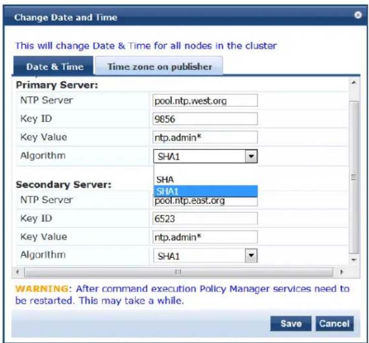
- Specify the Date & Time parameters as described in the following table, then click Save:
Table 292: Change Date and Time > Date & Time Parameters
| Parameter Description | |
| Synchronize time with NTP server | To synchronize with a Network Time Protocol (NTP) server, enable this check box (enabled by default).NOTE: You can also specify the date and time for the cluster manually by disabling the Synchronize time with NTP server check box and entering the current date and time in the dialog provided.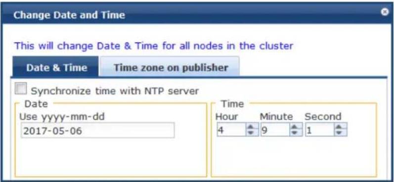 |
| Primary Server and Secondary Server | |
| NTP Server | Specify the IP address or host name for the Primary NTP server and the Secondary NTP server. |
| Key ID | The Key ID is a number that specifies the index for key values. The Key ID value can be from 1 to 65534 inclusive.Typically an NTP client and server have to trust the same key index and key value pair for authentication to succeed. |
| Key Value | The Key Value is a form of shared secret, which both the client and server use for authenticating NTP messages.The Key Value can be:Up to 20-character printable ASCII stringUp to 40-character hex valueWhen entering an ASCII string for the Key Value, note that it cannot contain the following characters:& (ampersand); (semicolon)` (grave accent)| (pipe)< (left angle bracket)> (right angle bracket)( (left parenthesis))(right parenthesis)Finally, the Key Value ASCII string must start and end with one of the following characters:- (hyphen)' (apostrophe)" (quote) |
| Algorithm | Select the following encryption type:SHASHA1NOTE: In FIPS mode, SHA is not a supported encryption type. |
Once you have saved the Date & Time configuration, you must restart Policy Manager services.

The Audit Viewer (Monitoring > Audit Viewer) tracks NTP configuration changes.
- To restart Policy Manager services, navigate to Administration > Server Manager > Server Configuration.
- Select the W-ClearPass server.
- From the Server Configuration page, select the Services Control tab.
- From the Action column, click Start for each service that needs to be restarted.
Specifying the Time Zone on the Publisher
To specify the time zone on the Publisher node:
- Click the Time Zone on Publisher tab.
Figure 531: Time Zone on Publisher Dialog
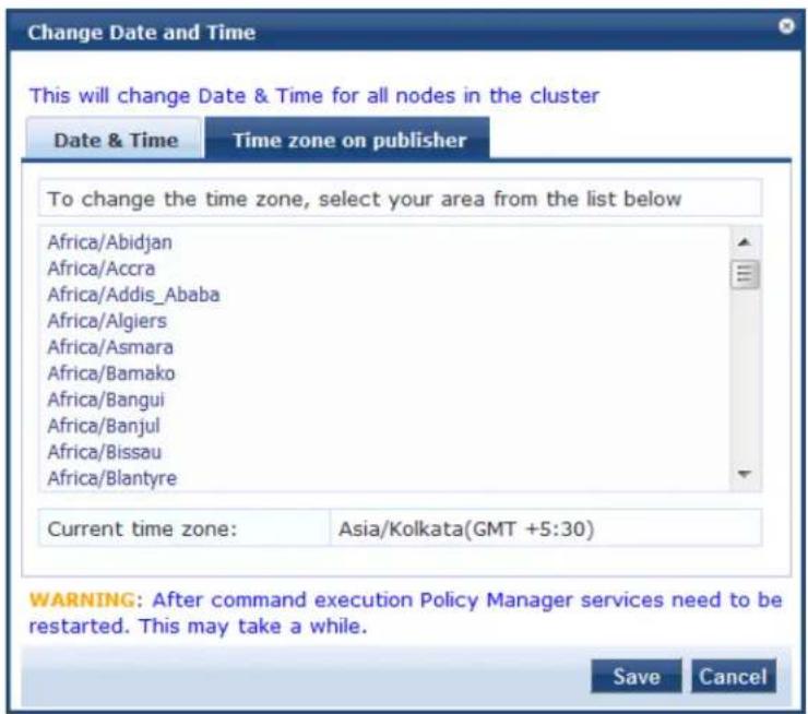
The time zones are listed in alphabetical order.
- Select the time zone where the Publisher node resides, then click Save.
This option is available only on the Publisher. To set the time zone on a Subscriber node, select the specific server and set the time zone from the server-specific page.

Changing the Cluster-Wide Password
To change the cluster-wide password:
- Navigate to Administration > Server Manager > Server Configuration.
The Server Configuration page opens.
- Click the Change Cluster Password link.
The Change Cluster Password dialog opens.
Figure 532: Change Cluster Password Dialog
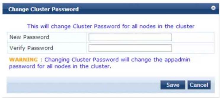
- Enter the new cluster password, then verify the password.
- Click Save.
Changing this password changes the password for the CLI user appadmin as well.

Managing Policy Manager Zones
This section provides the following information:
• About Policy Manager Zones
- Adding Policy Manager Zones
• Mapping Policy Manager Zones
About Policy Manager Zones
W-ClearPass Policy Manager shares a distributed cache of run-time states across all nodes in a cluster. T run-time states include:
- Roles and postures of connected entities
- Connection status of all endpoints running OnGuard
• Endpoint details gathered by OnGuard Agent
W-ClearPass Policy Manager uses this run-time state information to make policy decisions across multiple transactions.
In a deployment where a cluster spans WAN boundaries and multiple geographic zones, it is not necessary to share all of this run-time state across all nodes in the cluster.
For example, when endpoints present in one geographical area are not likely to authenticate or be presented another area, it is more efficient from a network bandwidth usage and processing perspective to restrict sharing of such run-time state to a given geographical area.
You can configure zones in W-ClearPass Policy Manager to match with the geographical areas in your deployment. There can be multiple zones per cluster, and each zone has a number of Dell Networking V ClearPass Policy Manager nodes that share their run-time state.
Adding Policy Manager Zones
To add or delete a Policy Manager Zone:
- Navigate to the Administration > Server Manager > Server Configuration page.
- Click the Manage Policy Manager Zones link.
Figure 533 displays the Policy manager Zones dialog:
Figure 533: Policy Manager Zones Dialog
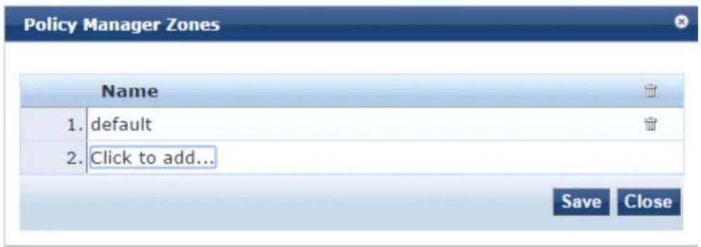
- To add a new Policy Manager Zone, click Click to add... and enter the name of the Policy Manager Zone to be added, click the Save icon, then click Save.
- To delete a zone, click the trash can icon—.
Mapping Policy Manager Zones
To configure the Policy Manager Zone you created:
- Navigate to Administration > Agents and Software Updates > OnGuard Settings.
The OnGuard Settings page opens.
- Click Policy Manager Zones.
The Mappings for Policy Manager Zones to OnGuard Clients page opens.
Figure 534: Mappings for Policy Manager Zones to OnGuard Clients Page
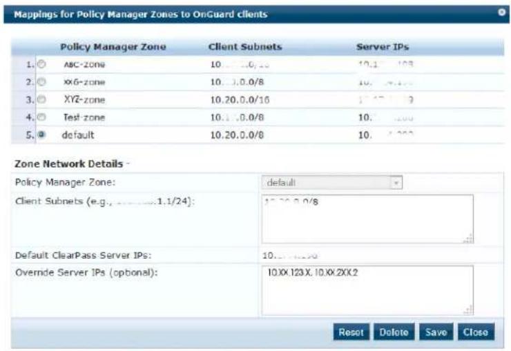
- Specify the Mappings for Policy Manager Zones to OnGuard Clients parameters as described in the following table:
Table 293: OnGuard Settings > Policy Manager Zones Parameters
| Parameter Action/Description | |
| Policy Manager Zone Lists | the Policy Manager zones with radial buttons for selection. |
| Client Subnets Displays the client subnet addresses specific to the Policy Manager zone. | |
| Server IPs Displays the server IP addresses specific to the Policy Manager zone. | |
| Zone Network Details | |
| Policy Manager Zone 1. Select the Policy Manager zone from the drop-down list that are created from the Administration > Server Manager > Server Configuration > Manage Policy Manager Zones page.If no Policy Manager zone is configured, the default Policy Manager zone is displayed in this field. | |
| Client Subnets 2. Specify the client subnets that are configured for the selected Policy Manager zone. | |
| Default W-ClearPass Server IPs | 3. Specify the IP address of the default W-ClearPass server. |
| Override Server IPs 4. Optionally, specify the IP addresses or the Fully Qualified Domain Name (FQDN) to which you want the OnGuard agent to send request in the sequence.You can specify the data port or load balancer IP address in this field. The IP addresses configured here will override the IP address configured in the Default ClearPass Server IPs field.For example, if you have configured the IP addresses 10.17.XXX.1, 10.17.XXX.2, and 10.17.XXX.3, OnGuard agent will send the request in the same sequence. | |
Configuring NetEvents Targets
NetEvents are a collection of information regarding various W-ClearPass Policy Manager users, endpoints, guests, authentications, accounting details, and so on. This information is periodically posted to a server configured as the NetEvents target.
If W-ClearPass Insight is enabled on a W-ClearPass Policy Manager server (see Enabling Insight and Specifying a Master Insight Node on page 770), it will receive net events from all other server nodes within the same W-ClearPass cluster.
If you want to post these details to an external server that can aggregate these events or to an external dedicated W-ClearPass Insight server for multiple W-ClearPass clusters, you have to configure an external NetEvents Target.
To configure an external NetEvents Target:
- Navigate to the Administration > Server Manager > Server Configuration page.
Figure 535: NetEvents Target Link on Server Configuration Page
Administration » Server Manager » Server Configuration
Server Configuration
Set Date & Time
Change Cluster Password
Manage Policy Manager Zones

Virtual IP Settings
* Clear Machine Authentication Cache
Make Subscriber
Cluster-Wide Parameters
Publisher Server: NIGHTLY-CPPM-31 [10.2.51.31]
| # | Server Name | Management Port | Data Port | Zone | Profile | Cluster Sync | Last Sync Time | |
| 1. | NIGHTLY- CPPM- 31 | 10. | default | Enabled | Enabled | |||
| Showing 1-1 of 1 | Collect Logs | Backup | Restore | Shutdown | Reboot |
2. Click the NetEvents Targets link.
The NetEvents Targets configuration dialog opens.
Figure 536: NetEvents Targets Configuration Dialog
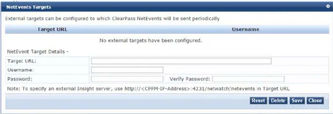
- Specify the NetEvents Targets parameters as described in the following table, then click Save:
Table 294: NetEvents Targets Parameters
| Parameter Action/Description | |
| Target URL 1. Enter the HTTP | URL for the service that supports posting to the NetEvents target and requires authentication using username and password.2. To specify an external Insight server, use the following Target URL:https://<W-ClearPass-IP-address>netwatch/netevents. |
| Username/Password 3. Enter | the W-ClearPass admin credentials configured for authentication for the HTTP service that is provided in the Target URL. |
| Reset button | Resets the values entered in this configuration dialog. |
| Delete button | Deletes the specified Target URL. |

Configuring Virtual IP Settings
You can configure two nodes in a cluster to share a virtual IP address. The virtual IP address is bound primary node by default. The secondary node takes over when the primary node is unavailable.
In a virtual machine deployment of W-ClearPass Policy Manager, you must enable forged transmits on the VMWare distributed virtual switch for the Virtual IP feature to be effective.
To configure a virtual IP address:
-
Navigate to the Administration > Server Manager > Server Configuration page.
-
Click the Virtual IP Settings link.
The Virtual IP Settings dialog opens:
Figure 537: Virtual IP Settings
![Virtual IP Settings Configure Virtual IPs for ClearPass High Availability Virtual IP Primary Node Secondary Node Status 1. 10.17.4.220 VM-240 [MGMT] VM-207 [MGMT] Enabled indicates current node serving Virtual IP Virtual IP Details - Virtual IP: Node Interface Subnet Primary Node: -select- Virtual IP Details - ------------------------------- ------------------------------- ------------------------------- ------------------------------- ------------------------------- ------------------------------- ------------------------------- ------------------------------- ------------------------------- ------------------------------- ------------------------------- ------------------------------- ------------------------------- ------------------------------- ------------------------------- ------------------------------- ------------------------------- ------------------------------- ------------------------------- ------------------------------- ------------------------------- ------------------------------- ------------------------------- ------------------------------- ------------------------------- ------------------------------- ------------------------------- ------------------------------- ------------------------------- ------------------------------- ---------------------------- Reset Delete Save Close](/content/2026/05/842116/images/3186b6d4ed7cd4423c8a396d26df98e1dbb79230a24a4a3dbf2db07d3f2ef79c.jpg)
- Specify the Virtual IP Settings parameters as described in the following table, then click Save:
Table 295: Virtual IP Settings Parameters
| Parameter | Action/Description |
| Virtual IP Enter the IP address you want to define as the virtual IP address. | |
| Primary Node | Select the server to use as the primary node. |
| Secondary Node | Select the server to use as the secondary node. |
| Interface | When you select the primary node and the secondary node, the Interface field is populated with that node's management interface IP address. |
| Subnet | The Subnet value for the management interface IP address is automatically populated when you select the primary node and secondary node. |
| Enabled | This parameter is enabled by default. |
Clearing Machine Authentication Cache
The Clear Machine Authentication Cache option clears the machine authentication cache from the local node; this operation is synced during battery replication. On confirmation, machine authentication cache i
cleared from all nodes in the cluster.
Once the machine authentication cache is cleared, it takes up to 5 seconds to resync the cache.
To clear machine authentication cache on all the nodes in a cluster:
- Navigate to the Administration > Server Manager > Server Configuration page.
The Server Configuration page opens:
Figure 538: Server Configuration Page > Clear Machine Authentication Cache

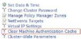
Publisher Server: Garuda-197 [10.17.4.197]
| # | Server Name △ | Management Port | Data Port | Zone | Profile | Cluster Sync | Last Sync Time |
| 1. | Garuda-197 | 10.17.4.197 | - | 198-zone | Enabled | Enabled | - |
| 2. | Garuda-198 | 10.17.4.198 | - | 198-zone | Enabled | Enabled | Dec 21, 2014 12:23:31 IST |
| 3. | Garuda-199 | 10.17.4.199 | - | 197-zone | Enabled | Enabled | Dec 21, 2014 12:23:31 IST |
| Showing 1-3 of 3 | Collect Logs | Backup | Restore | Cleanup Shutdown Reboot Drop Subscriber | |||
- Click the Clear Machine Authentication Cache link.
The following prompt is displayed:
Are you sure you want to clear machine authentication cache?
- To proceed with the operation, click Yes.
The following message appears:
Machine authentication cache cleared from all nodes
Making a Subscriber Node
In the Policy Manager cluster environment, the Publisher node acts as the master node. A Policy Manager cluster can contain only one Publisher node. Administration, configuration, and database write operations occur only on the Publisher node.
The Policy Manager appliance defaults to a Publisher node unless it is made a Subscriber node. Cluster commands can be used to change the state of the node, hence the Publisher can be made a Subscribe it is a Subscriber, the Make Subscriber link is not displayed.
Note the following caveats when adding a Subscriber node:
- As part of this operation, configuration changes are blocked on the Publisher node during the initial cluster sync process.
- All the application licenses on this server will be removed. To add and reactivate these application licenses, contact Support—navigate to Administration > Support > Contact Support for contact information.
To add a Subscriber node:
-
On a Publisher node, navigate to the Administration > Server Manager > Server Configuration page. The Server Configuration page opens.
-
Click the Make Subscriber link.
The Add Subscriber Node page opens:
Figure 539: Adding a Subscriber Node
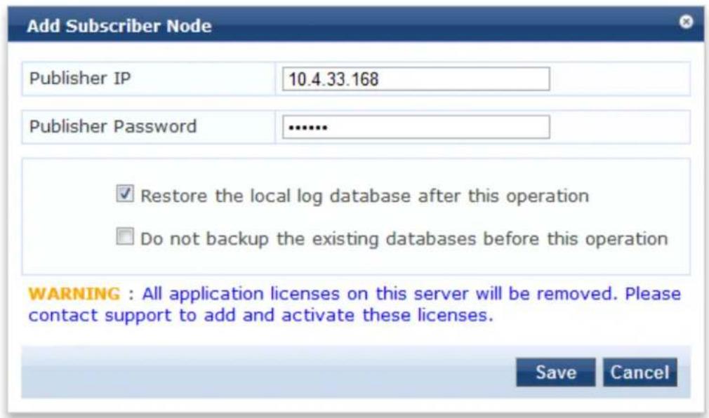
- Specify the Add Subscriber Node parameters as described in the following table, then click Save:
Table 296: Add Subscriber Node Parameters
| Parameter Action/Description | |
| Publisher IP Enter the Publisher node's IP address. | |
| Publisher Password Specify the Publisher | node's password.NOTE: The password specified here is the password for the CLI user appadmin. |
| Restore the local log database after this operation | To restore the log database after the Subscriber node has been added, select the check box. |
| Do not backup the existing databases before this operation | If you do not require a backup to the existing databases on this node, select the check box. |
Cluster-Wide Parameters
This section describes the following Cluster-Wide Parameters features:
- General Parameters
• Cleanup Intervals Parameters - Notifications Parameters
• Standby Publisher Parameters
• Virtual IP Parameters
• Mode Parameters - Database Parameters
• Profiler Parameters
General Parameters
You can configure the parameters that apply to all the nodes in a W-ClearPass cluster by configuring the Cluster-Wide Parameters.
To configure Cluster-Wide parameters:
-
Navigate to the Administration > Server Manager > Server Configuration page.
-
Select the Cluster-Wide Parameters link.
The Cluster-Wide Parameters page opens to the General page:
Figure 540: Cluster-Wide Parameters > General Page
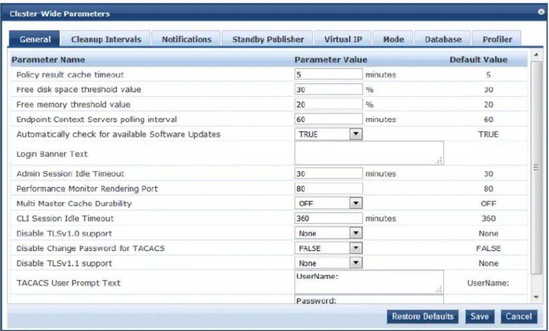
- Configure the Cluster-Wide Parameters > General parameters as described in the following table, then click Save.
Table 297: Cluster-Wide Parameters > General Page Parameters
| Parameter Action/Description | |
| Policy result cache timeout Specify the duration allowed in minutes to store the role mapping and posture results derived by the policy engine during a policy evaluation.A value of 0 disables caching.This result can then be used in subsequent evaluation of policies associated with a service, if the Use cached Roles and Posture attributes from previous sessions option is turned on for the service.NOTE: The value of the Policy result cache timeout field must be greater than the highest value set in the Health Check Interval (in hours) fields.For example, if you have created the profiles Student-Enforcement-Profile and Staff-Enforcement-Profile with health check interval configured, then the value of the Policy result cache timeout field must be greater than the highest value of the Health Check Quiet Period (in hours) value configured among the following profiles:Global Agent SettingsStudent-Enforcement-ProfileStaff-Enforcement-Profile | |
| Free disk space threshold value | Specify the percentage below which disk usage warnings are issued in the Monitoring > Event Viewer page.For example, a value of 30% indicates that a warning is issued only when the available disk space is 30% or lower.An error message similar to the following may appear in the System Event Details dialog:System is running with low disk space. Aggressive cleanup will be initiated when the available disk space falls below 80%. Current available disk space = 75% |
| Free memory threshold value | Specify the percentage below which RAM usage warnings are issued in the W-ClearPass Event Viewer.For example, a value of 30 indicates that a warning is issued only when the available RAM is 30% or lower. |
| Endpoint Context Servers polling interval | Enter the interval in minutes between polling of endpoint context servers.The default interval is 60 minutes. |
| Automatically check for available Software Updates | Specify whether to enable automatic checking for available software updates.The default it TRUE. |
| Login Banner Text Customize | the banner text that appears on the W-ClearPass login screen and CLI access window. |
| Admin Session Idle Timeout | Specify the maximum idle time permitted for admin users, beyond which the session times out.The default value is 30 minutes. The allowed range is 5 to 1440 minutes (24 hours). |
| Parameter Action/Description | |
| Performance Monitor Rendering Port | Specify the port for performance monitor rendering.The default value is 80. |
| Multi Master Cache Durability | For the Multi-Master Cache to survive most abrupt shutdowns, set this to Normal or Full.The default value is OFF.NOTE: Enabling this feature may result in some performance degradation. |
| CLI Session Idle Timeout Specify the maximum idle time permitted for CLI users, beyond which the session times out.The default value is 30 minutes. The allowed range is 5 to 1440 minutes (24 hours).When this parameter is changed, the changes take effect when the client o a new CLI session. Any active CLI sessions will continue to use the old tim setting—they have to be disconnected and reconnected for the updated tim value to take effect. | |
| Disable TLSv1.0 support To disable Transport Layer Security (TLS) v1.0 support, select one of the following options:NoneAdminNetworkAll | |
| Disable Change Password for TACACS | When logging in for TACACS user authentication:If set to FALSE (the default setting), after entering a blank password, you are presented with an option to change the TACACS user password.If set to TRUE, the option to enter the TACACS user password is displayed.The option to change the TACACS password is not displayed. |
| Disable TLSv1.0 support To disable Transport Layer Security (TLS) v1.1 support, select one of the following options:NoneAdminNetworkAll | |
| TACACS User Prompt TextTACACS Password Prompt Text | You can modify the text to be used for the TACACS username and password prompts as needed. The default TACACS prompts are as follows:UserName:Password: |
| TACACS Connection Idle Timeout | An idle TACACS login session is one in which the CLI operational mode prompt is displayed but there is no input from the keyboard. To close idle sessions automatically, you must configure a time limit for each login class.Specify the TACACS Connection Idle Timeout duration in seconds as needed.The default value is900 seconds(15 minutes).The minimum allowed value is60 seconds.The maximum allowed value is172800 seconds(two days). |
| Console Session Idle Timeout | Specify theConsole Session Idle Timeoutduration in minutes.The default value is360 minutes. TheConsole Session Idle Timeout:Must have a valid integer value (for example, a setting of 10.5 wouldn't be valid).The range of valid values is from 5 to 1440 minutes.The Audit Viewer captures the details about changes inConsole Session Idle Timeout: TheConsole Session Idle Timeout:Must have a valid integer value (for example, a setting of 10.5 wouldn't be valid).The range of valid values is from 5 to 1440 minutes.The Audit Viewer captures the details about changes inConsole Session Idle Timeout: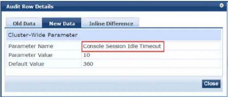 |
Cleanup Intervals Parameters
The following figure displays the Cluster-Wide Parameters > Cleanup Intervals dialog:
Figure 541: Cluster-Wide Parameters > Cleanup Intervals Dialog
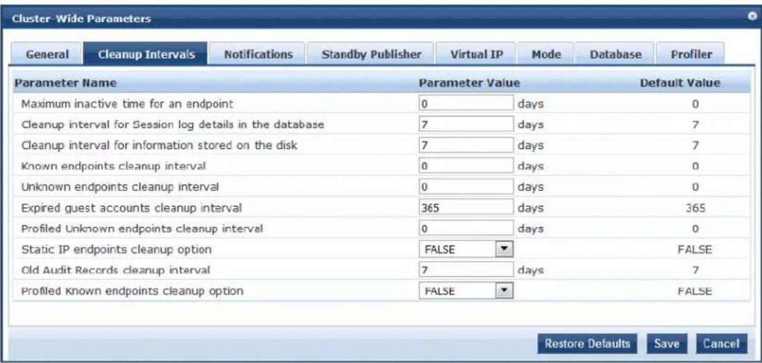
- Specify the Cluster-Wide Parameters > Cleanup Intervals parameters as described in the following table:
Table 298: Cluster-Wide Parameters > Cleanup Intervals Parameters
| Parameter Action/Description | |
| Maximum inactive time for an endpoint | Specify the duration in number of days to which an endpoint is retained in the endpoints table since its last authentication.A value of 0 specifies that no time limit is configured.If the endpoint is not authenticated for this period, the entry is removed from the endpoint table. |
| Cleanup interval for Session log details in the database | Specify the duration in number of days to keep the following data in the Policy Manager database:Session logs (found on the Monitoring > Live Monitoring > Access Tracker page)Event logs (found on the Monitoring > Event Viewer page)Machine authentication cacheThe default value is 7 days. |
| Cleanup interval for information stored on the disk | Specify the duration in number of days to keep log files that are written to the disk.The default value is 7 days. |
| Known endpoints cleanup interval | Specify the duration in number of days that W-ClearPass uses to determine when to start deleting known or disabled entries from the Endpoint repository.Known entries are deleted based on the last Added At value for each Endpoint. For example, if this value is 7, then known Endpoints that do not have the Added At value within the last 7 days are deleted.The default value is 0 days. This indicates that no cleanup interval is specified. |
| Unknown endpoints cleanup interval | Specify the duration in number of days that W-ClearPass uses to determine when to start deleting unknown entries from the Endpoint repository. Unknown entries are deleted based on the last Updated At value for each Endpoint. For example, if this value is 7, then unknown Endpoints that do not have the Updated At value within the last 7 days (stale endpoints) are deleted. The default value is 0 days. This indicates that no cleanup interval is specified. |
| Expired guest accounts cleanup interval | Specify the cleanup interval for expired guest accounts. This indicates the number of days after expiry that the cleanup occurs. A value of 0 specifies no expired guest accounts cleanup interval. The default value is 365 days. |
| Profiled Unknown endpoints cleanup interval | Specify the cleanup interval in number of days that W-ClearPass uses to determine when to start deleting profiled unknown entries from the Endpoint repository. Profiled unknown entries are deleted based on their last Updated At value for each Endpoint. For example, if this value is 7, then the Profiled Unknown Endpoints that do not have an Updated At value within the last 7 days are deleted. The default value is 0. |
| Static IP endpoints cleanup option | Specify whether to enable the option to cleanup static IP endpoints. The default option is FALSE. |
| Old Audit Records cleanup interval | Specify the cleanup interval in number of days that W-ClearPass uses to determine when to start deleting old audit records from the Audit Viewer page. The default value is 7 days. |
| Profiled Known endpoints cleanup option | Specify the cleanup interval in number of days that W-ClearPass uses to determine when to start deleting profiled known entries from the Endpoint repository. The default value is FALSE. |
Notifications Parameters
The following figure displays the Cluster-Wide Parameters > Notifications dialog:
Figure 542: Cluster-Wide Parameters > Notifications Dialog
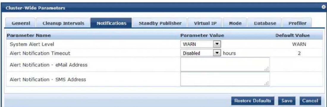
- Specify the Cluster-Wide Parameters > Notifications parameters as described in the following table:
Table 299: Cluster-Wide Parameters > Notifications Parameters
| Parameter Action/Description | |
| System Alert Level Specify the alert notifications that are generated for system events logged at this level or higher.·INFO: Alerts that provide Information, Warnings, and Error messages are generated.·WARN: Alerts that provide Warnings and Error messages are generated.·ERROR: Alerts that provide Error messages only are generated.·The default value is WARN. | |
| Alert Notification Timeout | Specify the timeout in hours that determines how often alert messages are generated and distributed.If you select Disabled, alert generation is disabled. The default value is 2 hours. |
| Alert Notification - eMail Address | Enter a comma-separated list of email addresses to which alert messages are sent. |
| Alert Notification - SMS Address | Enter a comma-separated list of phone numbers to which alert messages are sent. |
Standby Publisher Parameters
The Standby Publisher is the Publisher node in the cluster that is configured to come up in the event that Publisher node goes down.
The following figure displays the Cluster-Wide Parameters > Standby Publisher dialog:
Figure 543: Cluster-Wide Parameters > Standby Publisher Dialog
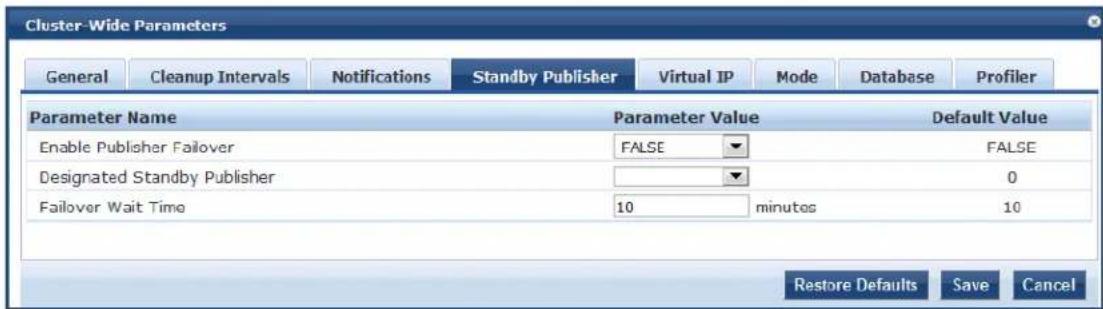
- Specify the Cluster-Wide Parameters > Standby Publisher parameters as described in the following table:
Table 300: Cluster-Wide Parameters > Standby Publisher Parameters
| Parameter Action/Description | |
| Enable Publisher Failover | To authorize a node in a cluster on the system to act as a publisher if the primary publisher fails, selectTRUE.The default value isFALSE. |
| Designated Standby Publisher | Select the server in the cluster to act as the standby publisher.The default value is0.NOTE:If the Standby Publisher is on a different subnet from the Publisher, then ensure that a reliable connection between the two subnets is available to avoid unwanted network segmentation and potential data loss from a false failover. |
| Failover Wait Time | Specify the time (in minutes) for which the secondary node must wait before it acquires a virtual IP address after the primary node fails.The default failover wait time is10minutes.This prevents the secondary node from taking over when the primary node is temporarily unavailable during a restart. |
Virtual IP Parameters
The following figure displays the Cluster-Wide Parameters > Virtual IP dialog:
Figure 544: Cluster-Wide Parameters > Virtual IP Dialog
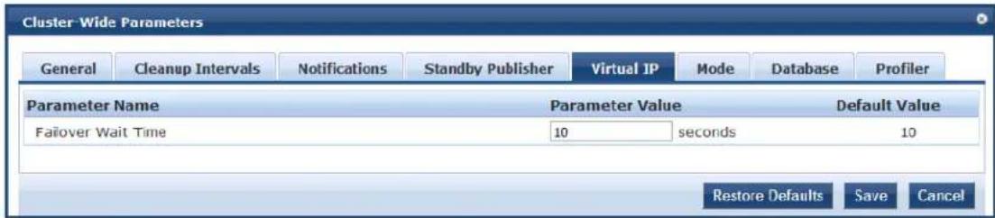
- Specify the Cluster-Wide Parameters > Virtual IP parameter as described in the following table:
Table 301: Cluster-Wide Parameters > Virtual IP Configuration Parameter
| Parameter | Action/Description |
| Failover Wait Time | Enter the number of seconds for the secondary node to wait after primary node failure be acquires the virtual IP address.The default fail-over wait time is 10 seconds in order for the secondary node to take over respond quickly to authentication access requests. |

You can define a virtual IP address with a primary server only (that is, without a secondary server) if required. This can be used to add an additional IP address to the W-ClearPass Policy Manager server without introducing any redundancy.
Mode Parameters
The Mode tab in the Cluster-Wide Parameters page allows you to enable or disable High Capacity Guest Mode and Common Criteria Mode.
Figure 545: Cluster-Wide Parameters Page
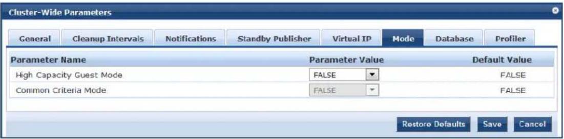
- Specify the Cluster-Wide Parameters > Mode parameters as described in the following table:
Table 302: Cluster-Wide Parameters > Mode Parameter
| Parameter Action/Description | |
| High Capacity Guest Mode | To enable or disable High Capacity Guest Mode, select TRUE or FALSE.The default is FALSE. |
| Common Criteria Mode | Common Criteria Mode is for specific deployments that require strict compliance to CoCriteria requirements.To enable or disable Common Criteria Mode, select TRUE or FALSE. The default is FALSE.When you set Common Criteria Mode to TRUE, the following Warning message is displayed:WARNING: Setting this value to TRUE enables strict validation of Certificates and changes to modules to comply to Common Criteria requirements. |
High Capacity Guest Mode
High Capacity Guest mode addresses the high-volume licensing requirements in the public-facing enterprise environment, where a large volume of unique endpoints need wireless access.
Figure 546: High Capacity Guest Mode Page
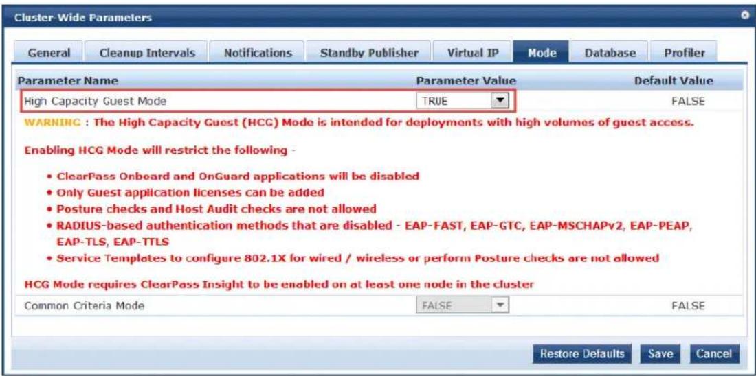
The licensing scheme in High Capacity Guest mode supports a high volume of user traffic in the followir public-facing enterprises where the number of endpoints changes every day:
• Transportation: Airports and rail stations
• Hospitality: Hotels, casinos, and resorts
• Healthcare: Hospitals, clinics, and health centers
• Retail: Shopping malls
• Large public venues: Stadiums, convention centers, and theaters
• Restaurants and coffee shops: Quick-serve restaurants
In enterprise deployments, W-ClearPass Policy Manager licensing accumulates the unique endpoint count in seven days, which can cause the number of licenses to exceed their limit.
To address this license limit in the public-facing enterprises environment, you can enable High Capacity Mode on a cluster.
In High Capacity Guest mode, the count of unique endpoints is reset every day, instead of accumulating count for seven days. In High Capacity Guest mode, only you can view the supported guest authentication methods supported in the Authentication Methods page.
RADIUS Authentication Methods That Cannot Be Enabled
When High Capacity Guest mode is enabled, you cannot enable the RADIUS services with the following authentication methods:
EAP-FAST
EAP-GTC
EAP-MSCHAPv2
EAP-PEAP
EAP-TLS
EAP-TTLS
Licensing Restrictions
You can add only guest licenses to High Capacity Guest mode. This mode is intended to handle only a volume of guest users in PFE environments. After enabling High Capacity Guest mode, you cannot add enterprise licenses.
If the number of licenses used exceeds the number of licenses purchased, a warning message appears for months after the number is exceeded. The number of licenses used is based on the daily moving average
In High Capacity Guest mode, a maximum of 2x licenses are allowed. For example, if you use the CP-HV platform (which supports 5,000 licenses), a maximum of 10,000 licenses are allowed.
Cluster Restrictions
When High Capacity Guest mode is enabled in a cluster, the following restrictions apply:
- Configuration settings cannot be moved from one cluster to another cluster that operates in High Capacity Guest mode.
- Restoring configuration is allowed only with the backup files from servers that have High Capacity Guest mode enabled.
- High Capacity Guest mode is intended only for high volumes of guest access.
- Use-case-related settings other than those for High Capacity Guest mode are restricted.
- OnGuard and Onboard access is restricted.
- The default cleanup interval values are reset.
- Only Guest application licenses are supported.
Insight Requirement
High Capacity Guest mode requires W-ClearPass Insight to be enabled on at least one node in the cluster
- Specify the default cleanup interval values when High Capacity Guest mode is enabled as described in following table:
Table 303: Cleanup Interval Values in High Capacity Guest Mode
| Parameter Action/Description | |
| Cleanup interval for Session log details in the database | The default value is 3days. |
| Known endpoints cleanup interval | The default value of the known endpoints cleanup interval is 3days. |
| Unknown endpoints cleanup interval | The default value of the unknown endpoints cleanup interval is 3days. |
| Expired guest accounts cleanup interval | The default value of the Expired guest accounts cleanup interval is 10 days. |
| Profiled endpoints cleanup interval | The default value of the Profiled endpoints cleanup interval is 3 days. |
| Old Audit Records cleanup interval | The default value of the Old Audit Records cleanup interval is 10 days. |
| Profiled Known endpoints cleanup option | Specify the cleanup interval in number of days that W-ClearPass uses to deter when to start deleting profiled known entries from the Endpoint repository. The default value is TRUE. |
Service Templates Supported in High Capacity Guest Mode
The following service templates are supported when High Capacity Guest mode is enabled:
• W-ClearPass Admin Access (Active Directory)
• W-ClearPass Admin SSO Login (SAML SP Service)
• W-ClearPass Identity Provider (SAML IdP Service)
- Encrypted Wireless Access via 802.1X Public PEAP method
- Guest Access
• Guest Access - Web Login
• Guest MAC Authentication
- OAuth2 API User Access
Service Types Supported in High Capacity Guest Mode
The following service types are supported when High Capacity Guest mode is enabled:
• MAC Authentication
• RADIUS Authorization
• RADIUS Enforcement
• RADIUS Proxy
• Dell Application Authentication
• Dell Application Authorization
• TACACS+ Enforcement
• Web-based Authentication
• Web-based Open Network Access
Authentication Methods Supported in High Capacity Guest Mode
The following authentication methods are used in service templates in High Capacity Guest mode:
PAP
CHAP
MSCHAP
EAP_MD5
• MAC_AUTH
• AUTHORIZE
EAP_PEAP_PUBLIC
Common Criteria Mode
Use Common Criteria Mode for deployments that require strict compliance to Common Criteria require Common Criteria is an international standard for security certification.
Figure 547: Cluster-Wide Parameters > Mode > Common Criteria Mode Page
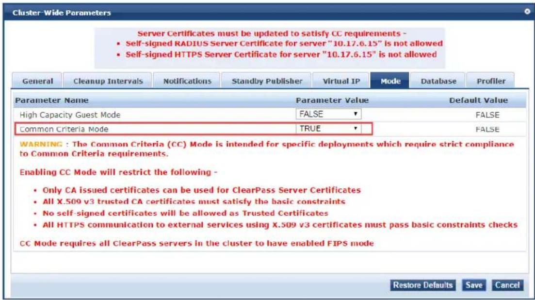
Common Criteria Mode has the following restrictions and requirements:
- Common Criteria Mode requires that all the W-ClearPass servers in the cluster must have FIPS mode enabled.
- Server certificates must be updated before you enable Common Criteria Mode.
- Only CA-issued certificates can be used for W-ClearPass server certificates.
- No self-signed certificates are allowed as trusted certificates.
- All X.509 v3 trusted CA certificates must satisfy the basic constraints.
X.509 is an important standard for a public key infrastructure to manage digital certificates and public encryption. X.509 is a key part of the Transport Layer Security protocol used to secure web and email communication.
- All HTTPS communication to external services using X.509 v3 certificates must pass the basic constraint checks.
Database Parameters
The following figure displays the Cluster-Wide Parameters > Database dialog:
Figure 548: Cluster-Wide Parameters > Database Dialog
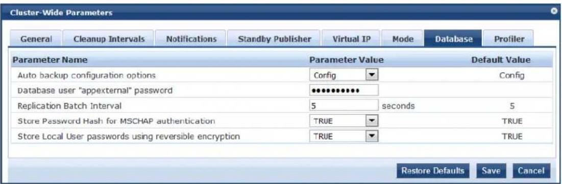
- Configure the Cluster-Wide Parameters > Database parameters as described in the following table:
Table 304: Cluster-Wide Parameters > Database Parameters
| Parameter Action/Description | |
| Auto backup configuration options | Select any of the following auto-backup configuration options:Off: Select this to not to perform periodic backups.Select Off before upgrading W-ClearPass Policy Manager to avoid the interference between Auto backup and migration process.Config: Perform a periodic backup of the configuration database only. This is the default auto backup configuration option.Config| SessionInfo: Perform a backup of the configuration database and the session log database.NOTE: It is recommended that you set this option to Off or Config before starting an upgrade. This ensures the Auto Backup process does not interfere with migrati post upgrade. If required, you can change this setting back to Config| SessionInfo 24 hours after upgrade completion. |
| Database user "appexternal" password | Enter the password for the appexternal username for this connection to the database. |
| Replication Batch Interval | Configure the time interval (in seconds) at which the subscribers synchronize with the Publisher.The default value is 5 seconds. The allowed range is 1 to 60 seconds. |
| Store Password Hash for MSCHAP authentication | To store passwords for admin and local users to Hash and NTLM hash format (which enables RADIUS MSCHAP authentications against admin or local repositories), set this to TRUE.If you set this to FALSE, RADIUS MSCHAP authentications are not possible because |
| Parameter Action/Description | |
| the NTLM hash passwords are removed for all the users.NOTE:When you set this value to TRUE, you must reset all the passwords to reenable RADIUS MSCHAP authentication against the user repositories. | |
| Store Local User Passwords using reversible encryption | To enable cleartext password comparison against local users, set this to TRUE.If you set this to FALSE, cleartext password comparison against local users is r possible because the reversible passwords for local users are removed.NOTE:After setting this value to TRUE, you must reset all the local user passwords to reenable cleartext password comparison against local users. |
Profiler Parameters
The following figure displays the Cluster-Wide Parameters > Profiler dialog:
Figure 549: Cluster-Wide Parameters > Profiler Dialog
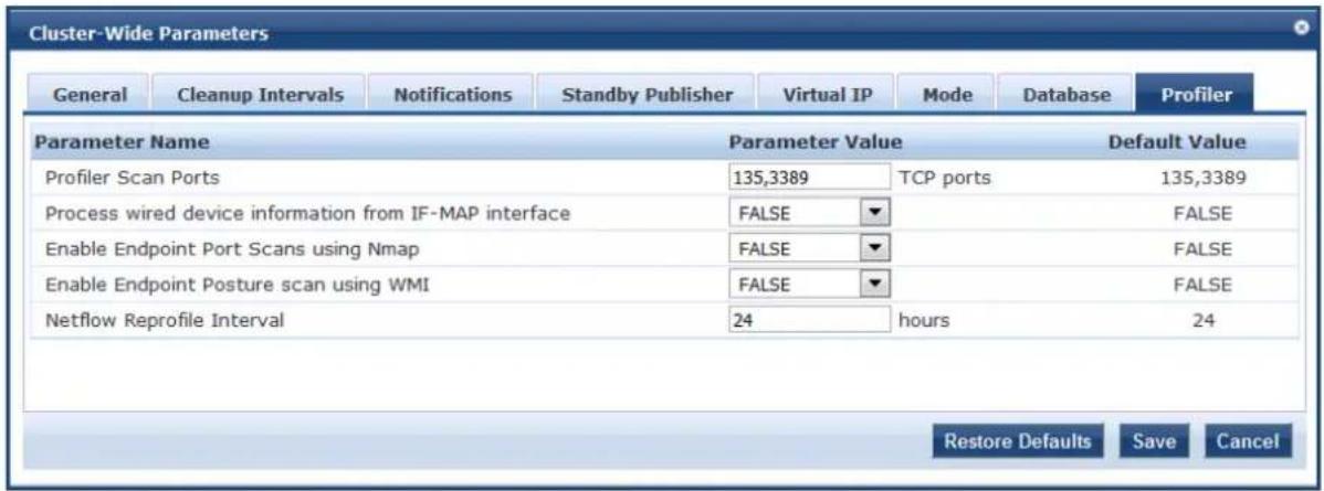
- Configure the Cluster-Wide Parameters > Profiler parameters as described in the following table:
Table 305: Cluster-Wide Parameters > Profiler Tab Parameters
| Parameter Action/Description | |
| Profiler Scan Ports To change the list of ports to scan and add custom fingerprints to classify based on them, enter the new TCP port numbers.The TCP ports scanner checks to see if the specified Profiler Scan Ports are open. The default TCP ports are 135 and 3389. | |
| Process wired device information from IF-MAP interface | Choose whether to process wired device information from the IF-MAP interface.The default is FALSE. |
| Enable Endpoint Port Scans using Nmap | Set this option to TRUE to enable Endpoint scans using Nmap (Network Mapper).NOTE: The Open Ports scanner is disabled when Nmap-based port scanning is enabled.When Nmap scan is enabled, the following warning is displayed:WARNING: Setting this value to TRUE enables active scan of the host for open ports. This can be resource intensive. Also, the Profiler Scan value is ignored when Nmap scan is enabled. |
| Enable Endpoint Port Scans using WMI | Set this option to TRUE to enable Endpoint scans using WMI (Windows Management Instrumentation). |
| Netflow Reprofile Interval Specify the | interval after which endpoints will be reprofiled.The default value is 24 hours. The minimum value is one hour. |
Collecting Logs
When you need to review performance or troubleshoot issues in detail, Policy Manager can compile and transactional and diagnostic data into several log files. These files are saved in Local Shared Folders and downloaded to your computer (see Downloading Local Shared Folders on page 570).
To collect logs:
- Navigate to Administration > Server Manager > Server Configuration.
The Server Configuration page opens.
- Click Collect Logs.
The Collect Logs dialog opens.
Figure 550: Collect Logs Dialog
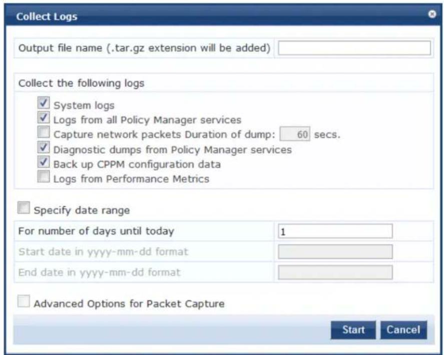
- Enter an output filename and add the .tar.gz extension to the filename.
- Select the types of logging information you want to collect. The types of logging are:

System Logs
- Logs from all Policy Manager services
■ Capture network packets Duration of dump in seconds.
Use this option only when you want to debug a problem. System performance can be severely impacted.
■ Diagnostic dumps from Policy Manager services
■ Back up Policy Manager configuration data
-
Enter the time period for which you want to collect the information.
-
Specify a number to collect logs for the number of days until the current day.
To collect logs for the specified time period, select the Specify date range check box and enter a start date and end date in yyyy-mm-dd format in the respective fields. -
Click Start.
You'll see the progress of the information collection.
-
To finish, click Close
-
To save the log file to your computer, click Download File.
If you are attempting to open a capture file (.cap or .pcap) using WireShark, untar or unzip the file (based on the f extension). When the entire file is extracted, navigate to the PacketCapture folder. In this folder, you will find a file with a .cap extension. WireShark can be used to open this file and study the network traffic.

Backing Up the Policy Manager Database
The backup file is automatically placed in the Shared Local Folder under folder type Backup Files (for details, see Downloading Local Shared Folders).
Backup files are in the gzipped tar format (tar.gz extension).
To back up the Policy Manager database:
- Navigate to the Administration > Server Manager > Server Configuration page.
- Click the Back Up button.
The Back up Policy Manager Database dialog opens:
Figure 551: Backup Policy Manager Database Dialog
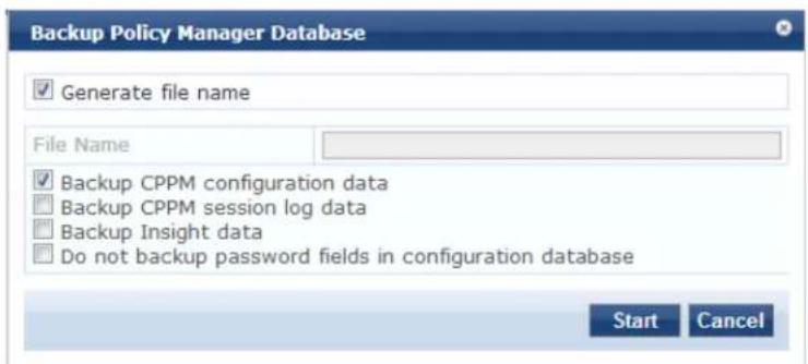
- Specify the Back up Policy Manager Database parameters as described in the following table, then click Start:
Table 306: Back up Policy Manager Database Parameters
| Parameter Action/Description | |
| Generate file name To enable Policy Manager to generate a file name for the database backup, select this check box.This option is enabled by default. | |
| File Name To manually specify the backup file name, click this check box, then enter the desired file name. | |
| Backup CPPM configuration data The option to back up Policy Manager configuration data is enabled by default. | |
| Backup CPPM session log data To enable back up of Policy Manager session log data, select this check box. | |
| Backup Insight data To enable back up of W-ClearPass Insight data, select this check box. | |
| Do not backup password fields in configuration database | If you don't want to backup the password fields in the configurat database, select this check box. |
Restoring Policy Manager Configuration Data
To restore the W-ClearPass Policy Manager configuration data:
- Navigate to the Administration > Server Manager > Server Configuration page.
- Click the Restore button.
The Restore Policy Manager Database dialog opens:
Figure 552: Restore Policy Manager Database Dialog
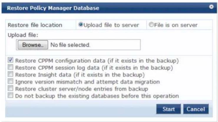
- Specify the Restore Policy Manager Database parameters as described in the following table, then click Start:
Table 307: Restore Policy Manager Database
| Parameter Action/Description | |
| Restore file location | Select eitherUpload file to server or File is on server. |
| Upload file path Browse to | select name of backup file.NOTE: This option is available only when the Upload file to server option is selected. |
| Shared backup files present on the server | If the files is on a server, select a file from the files in the local shared folders. (SeeDownloading Local Shared Folders.)NOTE: This is displayed only when theFile on serveroption is selected. |
| Restore CPPM configuration data (if it exists in the backup) | Select the check box to include an existing configuration data in the restore. |
| Restore CPPM session log data (if it exists in the backup). | Select the check box to include the log data in the restore. |
| Restore Insight data (if it exists in the backup) | Select the check box to include Insight reporting data in the restore. |
| Ignore version mismatch and attempt data migration | Select the check box if you are migrating configuration and/or log data from a backup file that was created with a previous compatible version. |
| Restore cluster server/node entries from backup. | Select the check box to include the cluster server/node entries in the restore. |
| Do not backup the existing databases before this operation. | Select the check box if you do not want to backup the existing databases before performing a restore. |
Performing a System Cleanup
You can perform a system cleanup operation to purge the following records:
• System and application log files
• Past authentication records
- Audit records
• Expired guest accounts
• Past auto and manual backups
- Stored reports
To perform a system cleanup:
- Navigate to the Administration > Server Manager > Server Configuration page.
- Click the Cleanup button.
The Force Cleanup Files dialog opens.
Figure 553: Force Cleanup Files Dialog
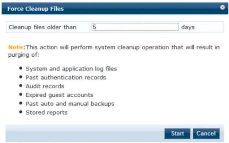
- Enter the number of days system files can remain before they are removed. The allowed range is 0 to 1 days.
- To initiate the cleanup process, click Start.
The Force Cleanup Files status report opens:
Figure 554: Force Cleanup Files Status Report
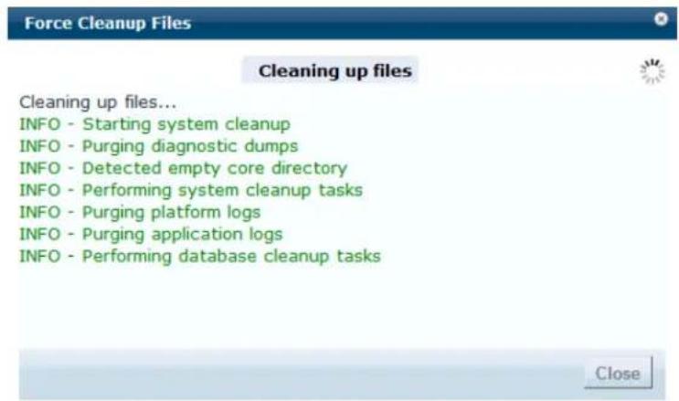
Shutting Down or Rebooting the Server
To shut down the current W-ClearPass server:
- Navigate to the Administration > Server Manager > Server Configuration page.
- Click the Shutdown button.
To reboot the current W-ClearPass server:
- Navigate to the Administration > Server Manager > Server Configuration page.
- Click the Reboot button.
Dropping a Subscriber Node
To drop a Subscribe node from the cluster:
- Navigate to the Administration > Server Manager > Server Configuration page.
- Select the node you want to drop from the cluster.
- Click the Drop Subscriber button.
This option is not available in a single-node deployment.

Log Configuration
To configure logs for services and system level, navigate to the Administration > Server Manager > Log Configuration page.
This section provides the following information:
• Service Log Configuration
• System Level Configuration
Service Log Configuration
The following figure displays the Service Log Configuration dialog:
Figure 555: Log Configuration > Service Log Configuration Tab
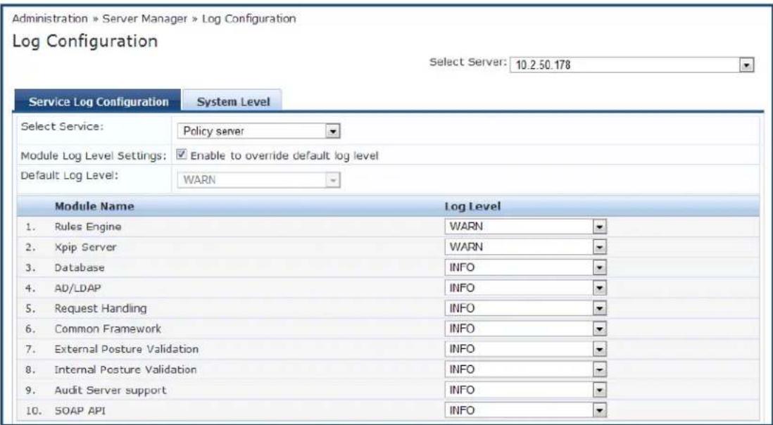
The following table describes the Service Log Configuration parameters:
Table 308: Log Configuration > Service Log Configuration Parameters
| Parameter Action/Description | |
| Select Server | 1. From the Select Server drop-down, specify the server for which you want to configure logs.All nodes in the cluster appear in the drop-down list. |
| Select Service 2. Specify the service for which you want to configure logs. | |
| Module Log Level Settings | 3. Select the Module Log Level Settings check box to set the log level for each module individually (listed in decreasing level of verbosity).For optimal performance you must run Policy Manager with the log level set to or FATAL):■ DEBUG■ INFO■ WARN■ ERROR■ FATALIf this option is disabled, then all module level logs are set to the default log le |
| Default Log Level 4. | Specify the default logging level for all modules.The Default Log Level drop-down list is available if the Module Log Level Settings option is disabled. Available options include the following:■ DEBUG■ INFO■ WARN■ ERROR■ FATALNOTE: Set this option first, and then override any specific modules as necessary. |
| Restore Defaults/Save | 5. Click Save to save changes.■ To restore the default settings, click Restore Defaults. |
System Level Configuration
The following figure displays the System Level dialog:
Figure 556: Log Configuration - System Level tab
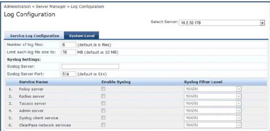
The following table describes the System Level tab parameters:
Table 309: Log Configuration > System Level Parameters
| Parameter Action/Description | |
| Select Server | 1. Specify the server for which you want to configure logs. |
| Number of log files | 2. Specify the number of log files of a specific module to keep at any given time. When a log file reaches the specified size (see Limit each log file size to), Policy Manager rolls the log over to another file until the specified number of log reached. Once the number of log files exceeds the specified value, Policy Manager overwrites the oldest file. |
| Limit each log file size to | 3. Specify the size of each log file before the log rolls over to the next file. The default value is 50 MB. |
| Syslog Settings | |
| Syslog Server | 4. Specify the name of the syslog server. Policy Manager sends the configured module logs to this syslog server. |
| Syslog Server Port | 5. Specify the syslog server port number. The default is 514. |
| Enable Syslog | 6. To override theSyslog Filter Levelfor a service, select theEnable Syslogcheck box. |
| Syslog Filter Level | 7. If desired, change the Syslog Filter Level.The currentSyslog Filter levelis based on the default log level specified on theService Log Configurationtab. |
| Restore Defaults/Save | 8. ClickSaveto save your changes.■ To restore the default settings, clickRestore Defaults. |
Downloading Local Shared Folders
The supported W-ClearPass folder types are:
• Backup files: Database backup files that are backed up manually.
- Log files: Log files backed up via the method described in Collecting Logs on page 562.
- Automated Backup files: Database backup files that are backed up automatically on a daily basis.
To download a local shared folder:
- Navigate to Administration > Server Manager > Local Shared Folders. The Local Shared Folders page opens.
- Choose a folder type from the Select folder drop-down list. The folders in the selected shared folder are displayed.
Figure 557: Local Shared Folders Page
Administration » Server Manager » Local Shared Folders
Local Shared Folders
Select folder: Backup files
| # | File Name | File Size | Last Modified Time |
| 1. | subscriber-setup-2-2014-12-29-13-41.tar.gz | 3.47 MB | Dec 29, 2014 13:41:22 IST |
| 2. | setup-2014-12-29-04-29-53-backup.tar.gz | 4.03 KB | Dec 29, 2014 09:59:55 IST |
- Select the folder you want to download. The following dialog opens:
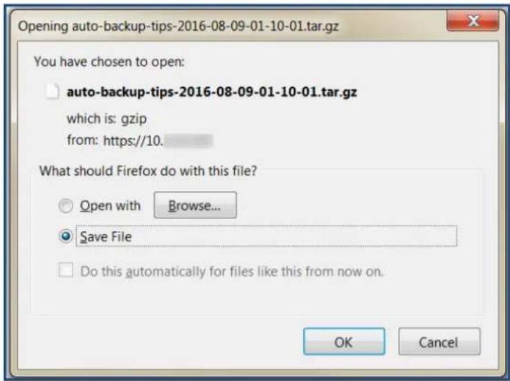
- You can either browse to an application to open the selected folder or save the tar.gz file to your ha
a. To open the folder, click Browse, select the application to open the tar.gz file, then click OK.
b. To save the file, select Save File, then click OK.
The file is downloaded to your system.
License Management
This section describes the following topics:
• About License Usage Limits
• Managing Licenses
- Adding an Application License
- Activating a Server License
• Activating an Application License
- Updating a Server License
• Updating an Application License
About License Usage Limits
This section provides an overview of how W-ClearPass handles breaches of the licensing usage limit.
- License utilization is based on the number of unique endpoints (devices) authenticating successfully.
- If the Policy Manager license is exceeded—even if a Guest and/or Onboard license is installed—Policy Manager will not register Guest or Onboard users until the license usage issue is resolved.
- Guest accounts created before the license usage issue will continue to authenticate. However, new guests won't be able to register or authenticate until the license usage issue is resolved.
- On exceeding the license limit, you receive an alert in the W-ClearPass user interface. The alert will remain for one month and reset only when there are no further license usage breaches.
- If you exceed your license count for four out of six months, you will be locked out of the W-ClearPass Policy Manager user interface until the license usage issue is resolved.
- If a license usage breach is an anomaly (that is, it is resolved within a month), the license usage limit alert is not sent.


Managing Licenses
The Licensing page shows all the licenses that are activated for the entire W-ClearPass Policy Manager cluster. You must have a W-ClearPass Policy Manager base license for every instance of the product.
If the number of licenses used exceeds the number of licenses purchased, you will see a warning four months after the number is exceeded. The number of used licenses is based on the daily average.
On a virtual machine instance of W-ClearPass, the permanent license must be entered.
To manage licenses, navigate to Administration > Server Manager > Licensing.
The Licensing page opens to the License Summary tab:
The Applications tab is activated on adding an application license such as OnGuard, Guest, or Onboard.
License Summary Tab
You can add and activate OnGuard, Guest, Onboard, and W-ClearPass Enterprise licenses.
The License Summary tab displays the number of purchased licenses for Policy Manager, OnGuard, Guest, Onboard, and W-ClearPass Enterprise.
Figure 558: Licensing > License Summary Tab
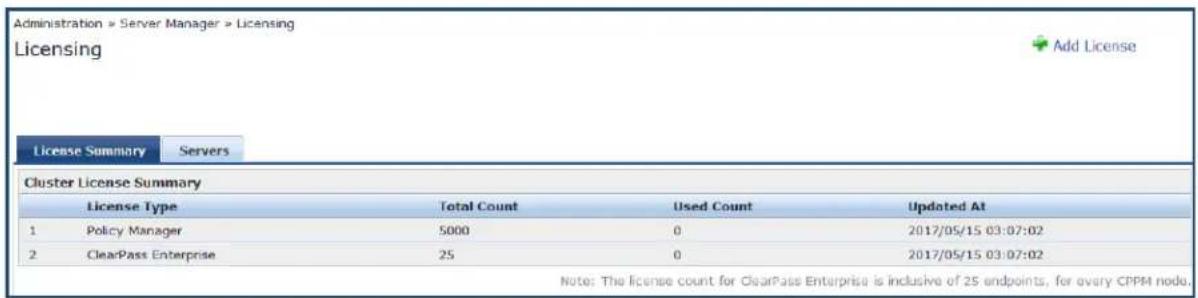
Licensing > Servers Tab
The Licensing > Servers tab displays the Policy Manager server IP address, the product type, license type, license activation status, and the date the application license was added.
Figure 559: Licensing > Servers Tab

Licensing > Applications Tab
The Licensing >Applications tab displays the W-ClearPass Policy Manager application license details such as product type, license type, number of endpoints, license duration, license activation status, and the date application license was added.
Figure 560: Licensing > Applications Tab

Adding an Application License
To add an application license:
- Navigate to Administration > Server Manager > Licensing.
- Click the Add License link at the top-right section of the page.
The Add License page opens.
Figure 561: Add License Page
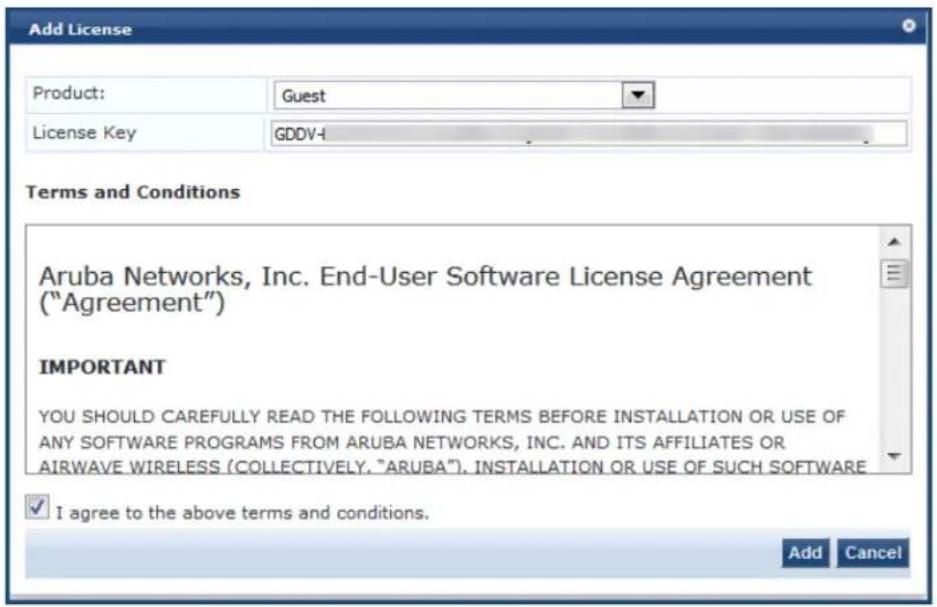
- Specify the Add License parameters as described in the following table:
Table 310: Add License Parameters
| Parameter Action/Description | |
| Product Choose a product from the Product drop-down list:OnGuardGuestOnboardW-ClearPass Enterprise | |
| License Key Enter the license key. | |
| Terms and Conditions | Click the I agree to the above terms and conditions check box. |
The Add button is now enabled.
4. Click Add.
You return to the Licensing > License Summary page, where the new application license is now listed and the following message is displayed:
Figure 562: License Added Successfully
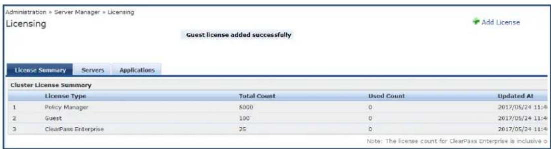
When you add an application license, the Applications tab is enabled to allow you to activate a new application license.
Activating a Server License
You activate an server license only once, when you first install W-ClearPass Policy Manager on a server.
• Online Activation
• Offline Activation: Creating a Case to Receive the Activation Key
Online Activation
To activate a W-ClearPass Policy Manager server license:
- Navigate to Administration > Server Manager > Licensing.
- Click the Servers tab.
A W-ClearPass server that is not yet activated has the keyword Activate next to the red circle in the Activation Status column.
Figure 563: ClearPass Server License

3. Click Activate.
The Activate License page opens.
Figure 564: Activate License Page
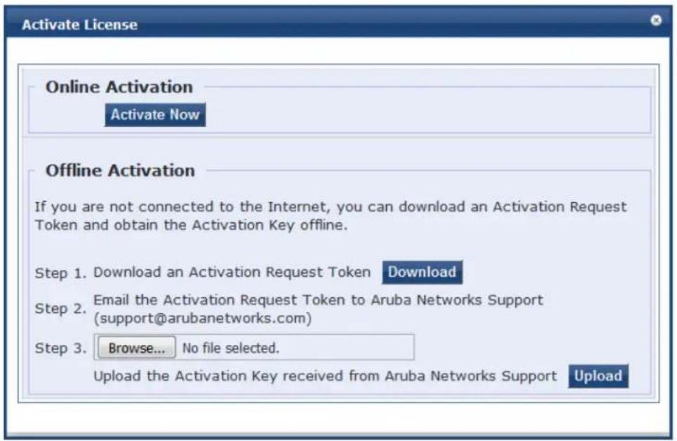
- In the Online Activation section, click Activate Now.
The W-ClearPass Policy Manager application license is now activated. The Applications tab > Activation Status column shows a green circle next to the keyword Activated.
Figure 565: ClearPass Server License Activated

Offline Activation: Creating a Case to Receive the Activation Key
If you are not connected to the Internet, you must submit a case through the HP Enterprise My Network portal:
- In the Offline Activation section, click Download to download an activation request token from the Policy Manager server.
- Go to the My Networking Portal and log in.
- Click the Support link.
- Click Open/View Case.
This will show all the cases you have submitted to Support.
- Click Open a New Case.
The Case Submission form is displayed.
- In the Case Submission > Problem Details section, complete all the fields in the Case Submission form as shown in Figure 566.
Figure 566: My Networking > Case Submission Form
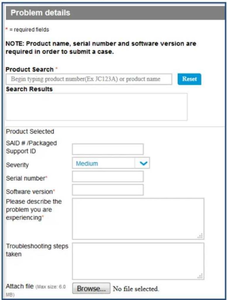
- To attach the activation token from W-ClearPass, click Browse and select the activation request token.
- Click Create a case.
Figure 567: Create a Case Button
- The Support team will activate the token and send you the activation key.
- Click Browse to locate the activation key file on your system, then click Upload.
Activating an Application License
• Online Activation
• Offline Activation: Creating a Case to Receive the Activation Key
After you add or update an application license, it must be activated. Adding or updating an application I enables the Applications tab on the Licensing page.
Online Activation
- Navigate to Administration > Server Manager > Licensing.
The Licensing page opens to the License Summary page.
- Select the Applications tab.
The new application licenses are listed. The Activation Status column shows a red circle next to the keyword Activate.
Figure 568: ClearPass Application Licenses Ready to Be Activated

- Click Activate.
The Activate License page opens.
Figure 569: Activate License Page
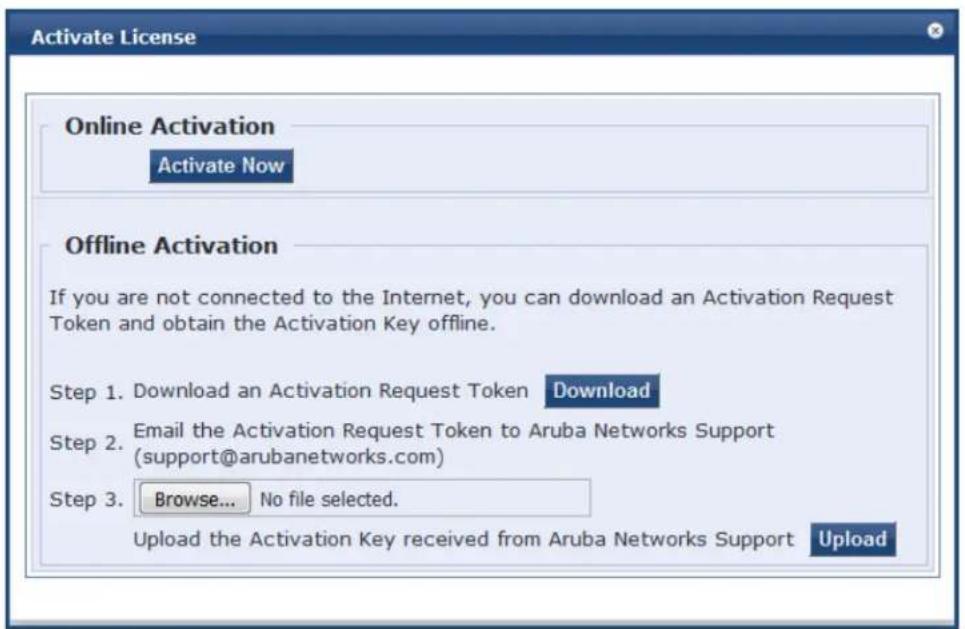
- In the Online Activation section, click Activate Now.
The selected application license is now activated. The Applications tab > Activation Status column shows a green circle next to the keyword Activated.
Figure 570: Application License Activated

Offline Activation: Creating a Case to Receive the Activation Key
If you are not connected to the Internet, you must submit a case through the HP Enterprise My Network portal:
- In the Offline Activation section, click Download to download an activation request token from the Policy Manager server.
- Go to the My Networking Portal and log in.
- Click the Support link.
- Click Open/View Case.
This will show all the cases you have submitted to Support.
- Click Open a New Case.
The Case Submission form is displayed.
- In the Case Submission > Problem Details section, complete all the fields in the Case Submission form as shown in Figure 571.
Figure 571: My Networking > Case Submission Form
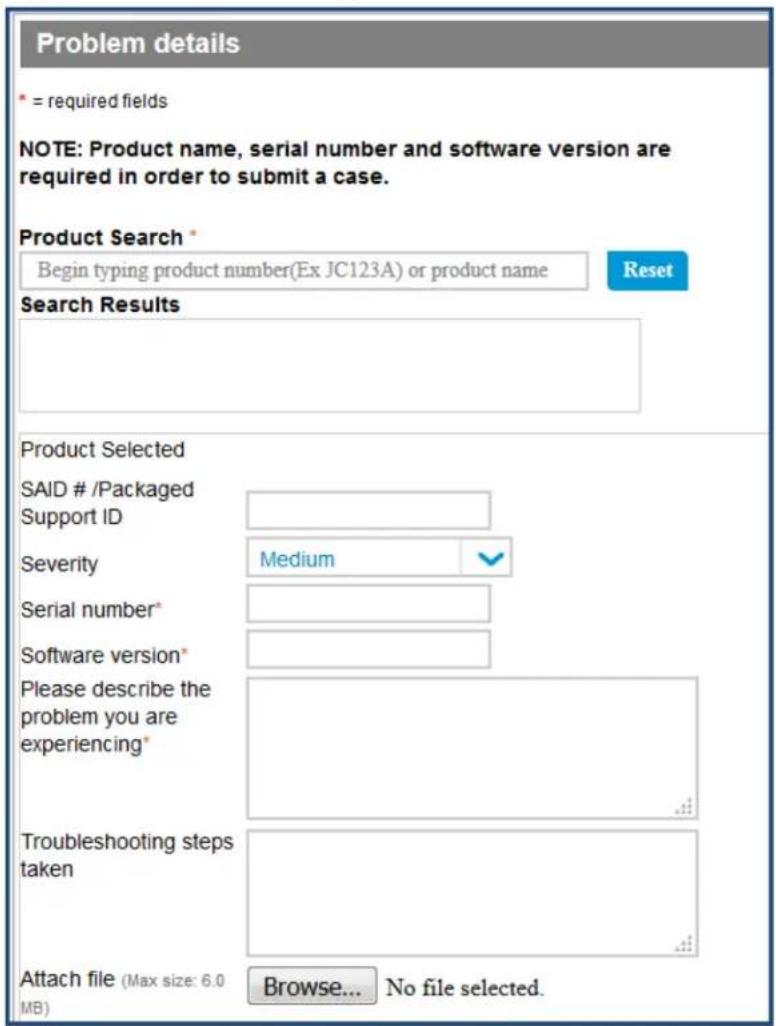
- To attach the activation token from W-ClearPass, click Browse and select the activation request token.
- Click Create a case.
Figure 572: Create a Case Button
- The Support team will activate the token and send you the activation key.
- Click Browse to locate the activation key file on your system, then click Upload.
Updating a Server License
Licenses typically require updating after they expire; for example, after the evaluation license expires, or capacity exceeds its licensed amount.
To update a W-ClearPass Policy Manager server license:
- Navigate to Administration > Server Manager > Licensing.
The Licensing page opens.
Figure 573: Licensing Page
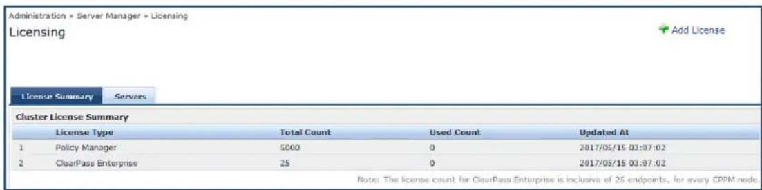
- Select the Servers tab.
Figure 574: Licensing > Servers Tab

- Click the W-ClearPass server entry.
The Update License dialog opens.
Figure 575: Update License Dialog
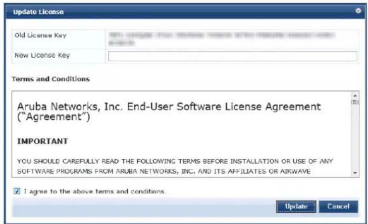
-
Enter the new license key.
-
Click the I agree to the above terms and conditions check box.
The Update button is now activated.
- Click Update.
The W-ClearPass server license is updated.
Updating an Application License
Application licenses typically require updating after they expire, for example, after the evaluation license expires, or when capacity exceeds its licensed amount of unique endpoints (devices) that can be authenti
To update an application license:
- Navigate to Administration > Server Manager > Licensing.
The Licensing page opens.
Figure 576: Licensing Page
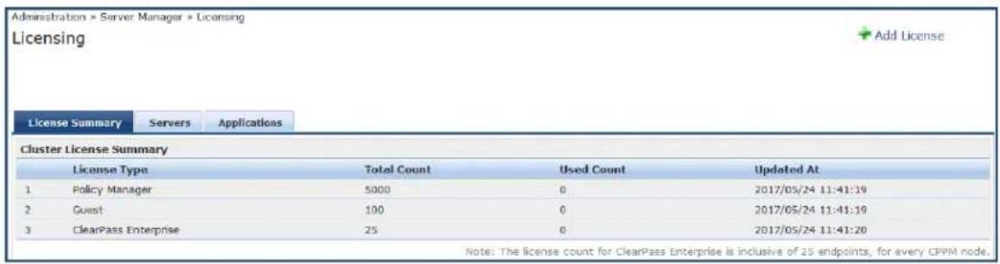
- Select the Applications tab.
Figure 577: Licensing Applications Tab

- Select the application license you need to update.
The Update License dialog opens.
Figure 578: Update License Dialog
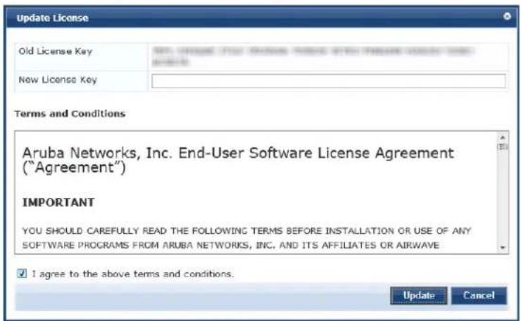
-
Enter the new license key.
-
Click the I agree to the above terms and conditions check box.
The Update button is now activated.
- Click Update.
The selected application license is updated.
SNMP Trap Receivers
This section provides the following information:
• SNMP Trap Receivers Main Page on page 582
- Adding an SNMP Trap Server on page 582
- Importing an SNMP Trap Server on page 584
- Exporting All SNMP Trap Servers on page 585
- Exporting an SNMP Trap Server on page 586
• Deleting an SNMP Trap Server on page 587
W-ClearPass Policy Manager sends SNMP traps that expose the following server information:
- System up-time: Provides information about how long the W-ClearPass server has been running.
- Network interface statistics [up/down]: Provides information about whether the network interface is up or down.
- Process monitoring information: Checks for the processes that should be running, including maximum and minimum number of allowed instances. Sends traps if there is a change in value of the maximum minimum numbers.
- Disk usage: Checks for disk space usage of a partition. The agent can check the amount of available disk space and make sure it's above the set limit. The value can be in percentage as well. Sends traps if change in the value.
- CPU load information: Checks for unreasonable load average values. For example, if CPU load average for one minute exceeds the configured value (in percentage), the W-ClearPass server sends a trap to the configured destination.
• Memory usage: Reports the W-ClearPass server's memory usage.
SNMP Trap Receivers Main Page
To view a list of SNMP trap receivers configured on the W-ClearPass Policy Manager server, navigate to Administration > External Servers > SNMP Trap Receivers.
The following figure displays the SNMP Trap Receivers page:
Figure 579: SNMP Trap Receivers Page
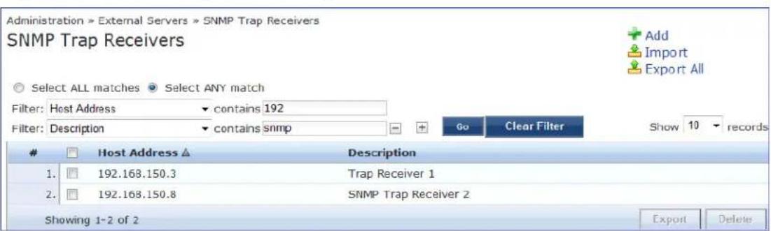
About the W-ClearPass SNMP Private MIB
For information about the W-ClearPass SNMP Private MIB, see W-ClearPass SNMP Private MIB on page 867.
Adding an SNMP Trap Server
A trap is an SNMP message sent from one application to another (which is typically on a remote host).
For SNMP trap server configuration, W-ClearPass provides the Type parameter to specify whether the SNMP notification is a standard Trap notification or an Inform notification (see Figure 580). An Inform notification is an acknowledged SNMP trap.
When you send an Inform notification, W-ClearPass uses an SNMP Engine ID when sending the message. The Engine ID is a unique identifier for the SNMP v3 agent. The engine ID is used with a hashing function to generate keys for authentication and encryption of SNMP v3 messages. The Engine ID is automatically generated when you enable the stand-alone SNMP agent.
The default value for the SNMP Engine ID is 6620000004030662. This value can be changed in the Engine ID field configured in the W-ClearPass Server Configuration > System Monitoring page (for details, see System Monitoring Page on page 523).
To receive traps, the same Engine ID value must be configured on the trap receiver side.
To add an SNMP trap server:
- Navigate to Administration > External Servers > SNMP Trap Receivers.
The SNMP Trap Receivers page opens.
- Click the Add link.
The Add SNMP Trap Server dialog opens.
Figure 580: Add SNMP Trap Server Dialog
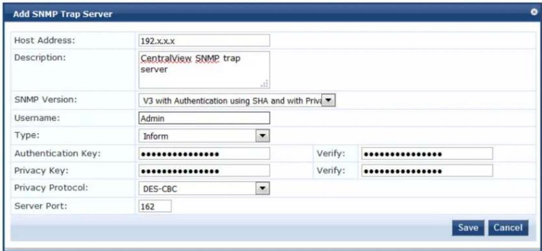
- Specify the Add SNMP Trap Server parameters as described in the following table, then click Save:
Table 311: Add SNMP Trap Server Parameters
| Parameter Action/Description | |
| Host Address | Enter the trap destination hostname or IP address. NOTE: This server must have an SNMP trap receiver or trap viewer installed. |
| Description | Enter a short description of the SNMP trap server. |
| SNMP Version | Select one of the following SNMP versions: |

Table 311: Add SNMP Trap Server Parameters (Continued)
| Parameter Action/Description | |
| SNMP v1 with community stringsSNMP v2 with community stringsSNMP v3 with no AuthenticationSNMP v3 with Authentication using MD5 and no PrivacySNMP v3 with Authentication using MD5 and with PrivacySNMP v3 with Authentication using SHA and no PrivacySNMP v3 with Authentication using SHA and with PrivacyNOTE: The MD5 authentication type is not supported when you use W-ClearPass Policy M in FIPS mode. | |
| Username Specify the Admin user name for SNMP operations.NOTE: This parameter is available in SNMP v3 only. | |
| Type From the Type drop-down, select the type of SNMP notification:InformTrap | |
| Authentication Key | Specify the SNMP v3 with authentication option (SHA or MD5).NOTE: The EAP-MD5 authentication type is not supported if you run W-ClearPass Policy Manager in FIPS mode.NOTE: Authentication Key is available in SNMP v3 only. |
| Privacy Key Specify the SNMP v3 with privacy option.NOTE: This parameter is available in SNMP v3 only. | |
| Privacy Protocol | Choose one of the available privacy protocols:DES-CBCAES-128NOTE: This parameter is available in SNMP v3 with Privacy only. Privacy allows for encryption of SNMP v3 messages to ensure confidentiality of data. |
| Server Port Specify the port number for sending the traps. By default, the port number is 162.NOTE: Configure the trap server firewall for traffic on this port. | |
Importing an SNMP Trap Server
To import an SNMP trap server:
- Navigate to Administration > External Servers > SNMP Trap Receivers.
- Click the Import link on the top right section of the page. Enter the details based on Table 312.
- Click Import.
The following figure displays the Import from file pop-up:
Figure 581: Import from file Pop-up
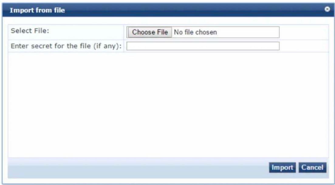
The following table describes the Import from file parameters:
Table 312: Import from file Parameters
| Parameter Description | |
| Select File Browse to the SNMP Trap Server configuration file to be imported. | |
| Enter secret for the file (if any) If the file was exported with a secret key for encryption, enter secret key here. | |
Exporting All SNMP Trap Servers
This link exports all configured SNMP Trap Receivers. To export all SNMP trap servers:
- Navigate to Administration > External Servers > SNMP Trap Receivers.
- Click the Export All link on the top right section of the page. Enter the details based on Table 313.
- Click Export.
- Enter the XML file name in the Save As dialog box.
- Click Save.
The following figure displays the Export to file pop-up:
Figure 582: Export to file Pop-up
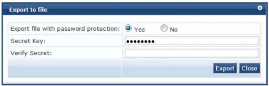
The following table describes the Export to file parameters:
Table 313: Export to file Parameters
| Parameter Description | |
| Export file with password protection | Choose Yes to export the file with password protection. |
| Secret Key Enter the secret key. | |
| Verify Secret Re-enter the secret key. |
Exporting an SNMP Trap Server
To export a single SNMP trap server:
- Navigate to Administration > External Servers > SNMP Trap Receivers.
- Select the Host Address from the list of check boxes and click Export. Enter the details based on Table 314.
- Enter the name of the XML file in the Save As dialog.
- Click Save.
The following figure displays the Export to file pop-up:
Figure 583: Export to file Pop-up
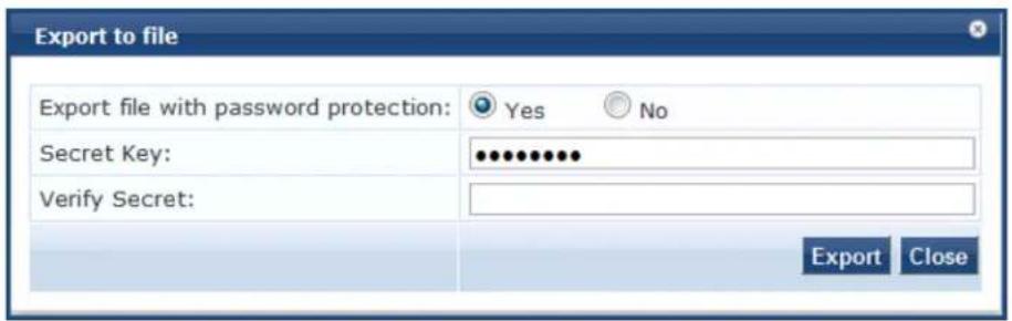
The following table describes the Export to file parameters:
Table 314: Export to file Parameters
| Parameter Description | |
| Export file with password protection | Choose Yes to export the file with password protection. |
| Secret Key Enter the secret key. | |
| Verify Secret Re-enter the secret key. |
Deleting an SNMP Trap Server
To delete a single SNMP trap server:
- Navigate to Administration > External Servers > SNMP Trap Receivers.
- Click the check box next to the Host Address entry and click Delete.
- Click Yes.
Syslog Targets
W-ClearPass Policy Manager can export session data (see Live Monitoring: Access Tracker on page 117), audit records (see Audit Viewer on page 167) and event records (see Event Viewer on page 169). This information can be sent to one or more syslog targets (servers). You configure syslog targets from this page. To config your syslog target, navigate to Administration > External Servers > Syslog Targets.
This section describes the following topics:
- Syslog Targets Main Page on page 587
- Adding a Syslog Target on page 588
- Importing a Syslog Target on page 589
- Exporting All Syslog Target on page 590
- Exporting a Syslog Target on page 590
- Exporting a Syslog Target on page 590
Syslog Targets Main Page
The following figure displays the Syslog Targets page:
Figure 584: Syslog Targets Page
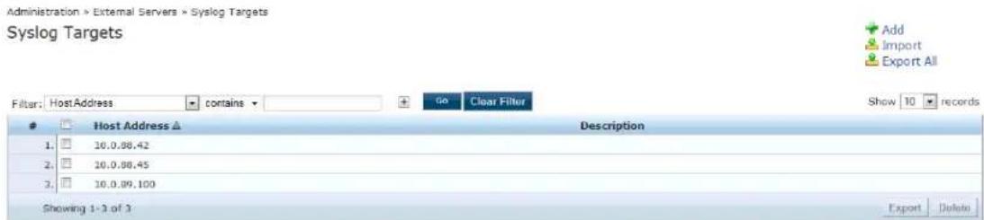
The following table describes the Syslog Targets parameters:
Table 315: Syslog Targets Parameters
| Parameter Description | |
| Add Opens the | Add Syslog Target pop-up. |
| Import | Opens the Import from file pop-up. You can import the syslog target from a file. |
| Export All | Opens the Export to file pop-up. You can export all the syslog target entries to a file. |
| Export | Opens the Export to file pop-up. With this option, you can export individual syslog targets. |
| Delete Deletes | a syslog target server. |
Adding a Syslog Target
To add a syslog target:
- Navigate to Administration > External Servers > Syslog Targets.
- Click the Add link on the top right section of the page. Enter the details based on Table 316.
- Click Save.
The following figure displays the Add Syslog Target pop-up:
Figure 585: Add Syslog Target Pop-up
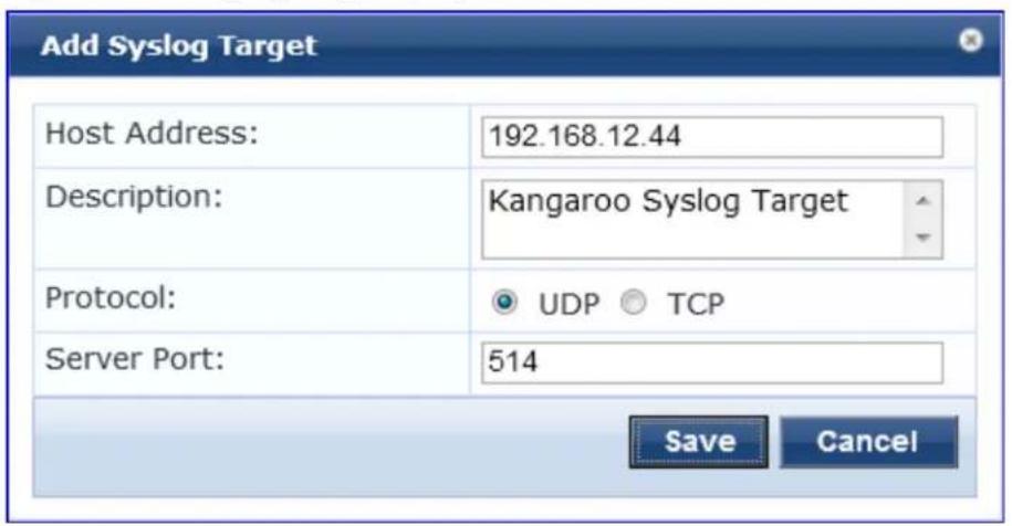
The following table describes the Add Syslog Target parameters:
Table 316: Add Syslog Target Parameters
| Parameter Description | |
| Host Address Syslog server hostname or IP address. | |
| Description Enter a short description of the syslog server. | |
| Protocol Select one of the following options:UDP: This option reduces overhead and latency.TCP: this option provides error checking and packet delivery validation. | |
| Server Port Port number for sending the syslog messages. Default port number is 514. |
Importing a Syslog Target
To import a syslog target:
- Navigate to Administration > External Servers > Syslog Targets.
- Click the Import link on the top right section of the page. Enter the details based on Table 317.
- Click Import.
The following figure displays the Import from file pop-up:
Figure 586: Import from file Pop-up
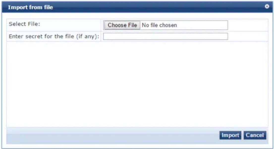
The following table describes the Import from file parameters:
Table 317: Import from file Parameters
| Parameter Description | |
| Select File Browse to the Syslog | Target configuration file to be imported. |
| Enter secret for the file (if any) | If the file was exported with a secret key for encryption, enter the same key here. |
Exporting All Syslog Target
To export all syslog targets:
- Navigate to Administration > External Servers > Syslog Targets.
- Click the Export All link on the top right section of the page. Enter the details based on Table 318.
- Click Export.
- Enter the XML file name in the Save As dialog box.
- Click Save.
The following figure displays the Export to file pop-up:
Figure 587: Export to file Pop-up
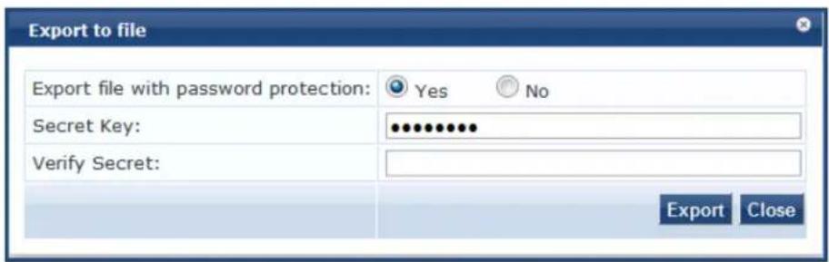
The following table describes the Export to file parameters:
Table 318: Export to file Parameters
| Parameter | Description |
| Export file with password protection | Choose Yes to export the file with password protection. |
| Secret Key | Enter the secret key. |
| Verify Secret | Re-enter the secret key. |
Exporting a Syslog Target
To export a syslog target:
- Navigate to Administration > External Servers > Syslog Targets.
-
Select the Host Address from the list of check boxes and click Export. Enter the details based on Table 318.
-
Enter the name of the XML file in the Save As dialog.
- Click Save.
The following figure displays the Export to file pop-up:
Figure 588: Export to file Pop-up
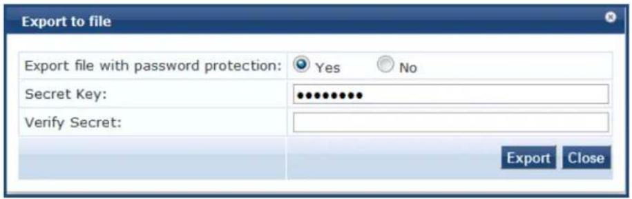
The following table describes the Export to file parameters:
Table 319: Export to file Parameters
| Parameter Description | |
| Export file with password protection | Choose Yes to export the file with password protection. |
| Secret Key Enter the secret key. | |
| Verify Secret Re-enter the secret key. |
Deleting a Syslog Target
To delete a syslog target:
- Navigate to Administration > External Servers > Syslog Targets.
- Click the check box next to the Host Address entry and click Delete.
- Click Yes.
Syslog Export Filters
This section describes the following topics:
• About Syslog Export Filters
- Syslog Export Filters Page on page 592
- Adding a Syslog Export Filter on page 592
- Importing a Syslog Filter on page 601
- Exporting All Syslog Filter on page 602
- Exporting a Syslog Filter on page 602
- Deleting a Syslog Filter on page 603
About Syslog Export Filters
Policy Manager can export session data (see Live Monitoring: Access Tracker on page 117), audit records (see Audit Viewer on page 167), and event records (see Event Viewer on page 169).
You configure syslog export filters to instruct Policy Manager where to send this information, and what I information should be sent through data filters.
Syslog Export Filters Page
To configure syslog export filters:
- Navigate to Administration > External Servers > Syslog Export Filters.
The Syslog Export Filters page opens.
Figure 589: Syslog Export Filters Page
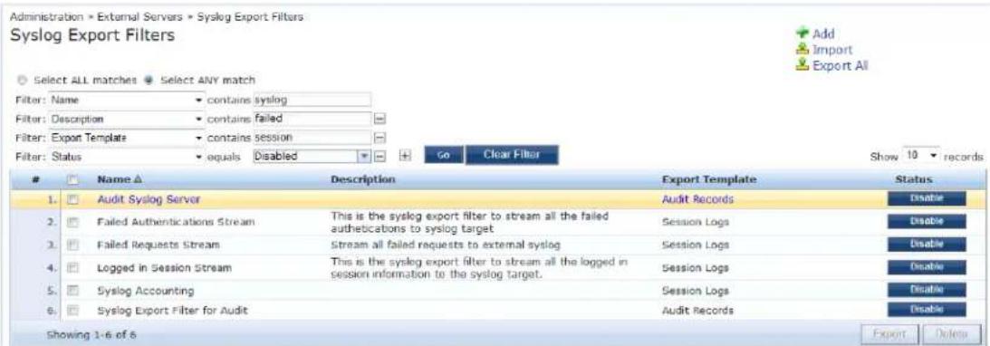
The following table describes the Syslog Export Filters parameters:
Table 320: Syslog Export Filters Page Parameters
| Parameter Action/Description | |
| Name Displays the name of the syslog export filter. | |
| Description Displays the description of the syslog export filter. | |
| Export Template | Displays the name of the Export Template selected in the Add Syslog Export Filter dialog (see Adding a Syslog Export Filter on page 592). |
| Export Event Format | Displays the Export Event Format Type selected in the Add Syslog Export Filter dialog. |
| Enable/Disable | Enable or disable the syslog export filter. |
| Export | Opens the Export to file dialog. With this option, you can export individual syslog export filters. |
| Delete | Deletes a syslog export filter. |
Adding a Syslog Export Filter
You can use filters to select the data sent from the Log server to the Syslog server. First add a Syslog described below. You can then export and apply the Syslog filters separately to different kinds of logs.
To add a syslog export filter:
-
Navigate to Administration > External Servers > Syslog Export Filters.
-
From the Syslog Export Filters page, click Add.
The Add Syslog Filters page opens to the General tab.
Figure 590: Add Syslog Export Filters Page > General Tab
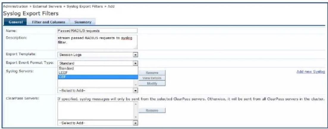
The Filter and Columns tab shown in the figure above is only visible if you select Insight Logs or Session Logs as the export template. For more information, see Filter and Columns Tab on page 597.
The following table describes the Add Syslog Export Filters > General tab parameters:
Table 321: Add Syslog Export Filters > General Tab Parameters
| Parameter Action/Description | |
| Name Enter the name of the syslog export filter. | |
| Description Enter the description that provides additional information about the syslog export filter (recommended). | |
| Export Template | Select any one of the templates from the following options:Audit RecordsInsight LogsSession LogsSystem EventsNOTE: If you select Insight Logs or Session Logs, the Filter and Columns tab is enabled. For more information, see Filter and Columns Tab on page 597. |

Table 321: Add Syslog Export Filters > General Tab Parameters (Continued)
| Parameter Action/Description | |
| Export Event Format Type | Select any one of the export event formats from the following options:Standard: Select this event format type to send the event types in raw syslog format. This is the default event format type.LEEF: Select this event format type to send the event types in Log Enhanced Event Format (LEEF).CEF: Select this event format type to send the event types in Common Event Format (CEF). For sample event format types, see Export Event Format Types—Examples on page 594. |
| Syslog Servers | Syslog servers define the receivers of syslog messages sent by servers in the W-ClearPass cluster.To add a W-ClearPass syslog server, select it from the Select to Add drop-down list.To add a new W-ClearPass syslog server, click the Add New Syslog Target link (for more information, see Adding a Syslog Target on page 588).To view details about a syslog server, select the syslog server, then click View Details.To change details about a syslog server, select the syslog server, then click Modify. For more information, see Adding a Syslog Target on page 588.To remove a syslog server (from receiving syslog messages), select the syslog server, then click Remove. |
| W-ClearPass Servers | You can designate syslog messages to be sent from exactly one server in the W-ClearPass cluster or from all of them.To add a W-ClearPass server, select it from the Select to Add drop-down list.To remove the W-ClearPass server, select the W-ClearPass server, then click Remove.NOTE: When no servers are listed, syslog messages are sent from all servers in the clust |
Export Event Format Types—Examples
This section provides several examples of Standard, LEEF, and CEF event format types for the syslog exp filter templates.
Standard Event Format Type > Audit Events
The following example describes the Standard event format type for the Audit Events syslog export filter template:
Mar 20 21:18:56 10.17.5.228 2017-01-19 21:19:50,118 10.17.5.228 Audit Logs 96 1 0
TimestampFormat=yyyy-MM-dd
HH:mm:ss,S,User=clusteradmin,Category=Endpoint,Action=ADD,EntityName=34a39527afc0,src=10.17.5.228,Timestamp=Jan 19, 2017 21:18:54 IST
Mar 20 21:20:56 10.17.5.228 2017-01-19 21:21:50,111 10.17.5.228 Audit Logs 97 1 0
TimestampFormat=yyyy-MM-dd HH:mm:ss,S,User=admin,Category=Cluster-wide
Parameter,Action=MODIFY,EntityName=Endpoint Context Servers polling
interval,src=10.17.5.228,Timestamp=Jan 19, 2017 21:20:22 IST
Mar 21 09:28:59 10.17.5.228 2017-01-20 09:29:54,3 10.17.5.228 Audit Logs 99 1 0
TimestampFormat=yyyy-MM-dd HH:mm:ss,S,User=admin,Category=Network
Device,Action=REMOVE,EntityName=1.1.1.1,src=10.17.5.228,Timestamp=Jan 20, 2017 09:29:13 IST
Standard Event Format Type > System Events
The following example describes the Standard event format type for the System Events syslog export filter template:
Mar 21 16:46:29 10.17.5.228 2017-01-20 16:47:23,880 10.17.5.228 System Events 0 1 0 TimestampFormat=yyyy-MM-dd HH:mm:ss,S,Description=User: arubasupport\nClient IP Address:
10.20.23.178, Category=Logged in, Action=None, Level=INFO, src=10.17.5.228, Component=Support Shell, Timestamp=Jan 20, 2015 16:45:59 IST Mar 21 16:49:10 10.17.5.228 2017-01-20 16:50:05, 210 10.17.5.228 System Events 1 1 0 TimestampFormat=yyyy-MM-dd HH:mm:ss, S, Description='Failed to start ClearPass Virtual IP service', Category=start, Action=Failed, Level=WARN, src=10.17.5.228, Component=ClearPass Virtual IP service, Timestamp=Jan 20, 2017 16:48:53 IST 2015-01-20 16:50:05, 210 [pool-6-thread-1] [R:] DEBUG com.avenda.tips.syslog.Syslogger - 2017-01-20 16:50:05, 210 10.17.5.228 System Events 2 1 0 TimestampFormat=yyyy-MM-dd HH:mm:ss, S, Description=Performed action stop on cpass-domain-server_ CPATS, Category=stop, Action=Success, Level=INFO, src=10.17.5.228, Component=cpass-domain-server_ CPATS, Timestamp=Jan 20, 2017 16:48:57 IST 2015-01-20 16:50:05, 211 [pool-6-thread-1] [R:] DEBUG com.avenda.tips.syslog.Syslogger - 2017-01-20 16:50:05, 211 10.17.5.228 System Events 3 1 0 TimestampFormat=yyyy-MM-dd HH:mm:ss, S, Description=Performed action start on cpass-domain-server_ CPATS, Category=start, Action=Success, Level=INFO, src=10.17.5.228, Component=cpass-domain-server_ CPATS, Timestamp=Jan 20, 2017 16:49:00 IST
Standard Event Format Type > Session Events
The following example describes the Standard event format type for the Session Events syslog export filter template:
Mar 21 16:31:49 10.17.5.211 2015-01-20 16:32:41,552 10.17.5.211 Radius Session Logs 4 1 0 Common.NAS-IP-Address=10.17.4.7,RADIUS.Acct-Delay-Time=null,RADIUS.Acct-Framed-IP- Address=null,RADIUS.Auth-Source=AD:win2008R2-64bit.bangalore.avendasys.com,RADIUS.Acct- Timestamp=null,RADIUS.Acct-Authentic=null,RADIUS.Auth-Method=EAP-PEAP,EAP- MSCHAPv2,Common.Host-MAC-Address=58a2b5d05ac9,RADIUS.Acct-Termination-Cause=null,RADIUS.Acct- Service-Name=null,RADIUS.Acct-Session-Time=null,TimestampFormat=yyyy-MM-dd HH:mm:ss,S,RADIUS.Acct-NAS-Port=null,Common.Usage=test1,RADIUS.Acct-Session- Id=null,RADIUS.Acct-Called-Station-Id=null,RADIUS.Acct-NAS-Port- Type=null,src=10.17.5.211,RADIUS.Acct-NAS-IP-Address=null,Common.Service=Test Post Authentication Rules,RADIUS.Acct-Input-Pkts=null,RADIUS.Acct-Status-Type=null,RADIUS.Acct- Calling-Station-Id=null,Common.Request-Timestamp=2015-01-20 16:31:46+05:30,RADIUS.Acct-Output- Pkts=null,RADIUS.Acct-Output-Octets=null,RADIUS.Acct-Username=null,RADIUS.Acct-Input- Octets=null Mar 21 16:31:49 10.17.5.211 2015-01-20 16:32:41,550 10.17.5.211 Radius Session Logs 3 2 0 Common.NAS-IP-Address=10.17.4.7,RADIUS.Acct-Delay-Time=0,RADIUS.Acct-Framed-IP- Address=10.17.4.148,RADIUS.Auth-Source=AD:win2008R2-64bit.bangalore.avendasys.com,RADIUS.Acct- Timestamp=2015-01-20 16:31:50+05:30,RADIUS.Acct-Authentic=RADIUS,RADIUS.Auth-Method=EAP- PEAP,EAP-MSCHAPv2,Common.Host-MAC-Address=e0f847la5450,RADIUS.Acct-Termination- Cause=null,RADIUS.Acct-Service-Name=null,RADIUS.Acct-Session-Time=null,TimestampFormat=yyyy- MM-dd HH:mm:ss,S,RADIUS.Acct-NAS-Port=0,Common.Usage=test1,RADIUS.Acct-Session- Id=test1E0F8471A5450-54BE336C,RADIUS.Acct-Called-Station-Id=000B8661CD70,RADIUS.Acct-NAS-Port- Type=Wireless-802.11,src=10.17.5.211,RADIUS.Acct-NAS-IP-Address=10.17.4.7,Common Service=Test Post Authentication Rules,RADIUS.Acct-Input-Pkts=null,RADIUS.Acct-Status- Type=Start,RADIUS.Acct-Calling-Station-Id=E0F8471A5450,Common.Request-Timestamp=2015-01-20 16:31:45+05:30,RADIUS.Acct-Output-Pkts=null Mar 21 16:35:58 10.17.5.228 2015-01-20 16:36:52,346 10.17.5.228 Tacacs authetnications 2 1 0 TACACS.Request-Type=TACACS_AUTHORIZATION,TACACS.Enforcement-Profiles=[TACACS Super Admin],TACACS.Acct-Flags=null,TACACS.Authen-Service=AUTHEN_SVC_NONE,TACACS.Acct-Session- Id=null,TACACS.Remote-Address=10.20.23.178,Common.Request-Timestamp=2015-01-20 16:34:54.647+05:30,TimestampFormat=yyyy-MM-dd HH:mm:ss,S,TACACS.Authen-Action=,TACACS.Authen- Method=AUTHEN_METH_TACACSPLUS,Common.Usage=a,TACACS.Authen-Type=AUTHEN_TYPE_ PAP,TACACS.Auth-Source=[Local User Repository],src=10.17.5.228,TACACS.Privilege- Level=1,Common.Service=[Policy Manager Admin Network Login Service] Mar 21 16:35:58 10.17.5.228 2017-01-20 16:36:52,346 10.17.5.228 Tacacs authetnications 3 1 0 TACACS.Request-Type=TACACS_AUTHENTICATION,TACACS.Enforcement-Profiles=[TACACS Super Admin],TACACS.Acct-Flags=null,TACACS.Authen-Service=AUTHEN_SVC_NONE,TACACS.Acct-Session- Id=null,TACACS.Remote-Address=10.20.23.178,Common.Request-Timestamp=2017-01-20 16:34:54.647+05:30,TimestampFormat=yyyy-MM-dd HH:mm:ss,S,TACACS.Authen-Action=AUTHEN_ACTION_ LOGIN,TACACS.Authen-Method=AUTHEN_METH_TACACSPLUS,Common.Usage=a,TACACS.Authen-Type=AUTHEN_ TYPE_PAP,TACACS.Auth-Source=[Local User Repository],src=10.17.5.228,TACACS.Privilege- Level=1,Common.Service=[Policy Manager Admin Network Login Service]
LEEF Event Format Type > Insight Logs
The following example describes the LEEF event format type for the Insight Logs syslog export filter template:
Dec 03 2017 16:50:44.085 IST 10.17.4.208 LEEF:1.0|Dell|ClearPass|6.5.0.69058|0-1-0|Auth.Usage=host/Asif-Test-PC2 Auth.Authorization-Sources=null Auth.Login-Status=216 Auth.Request-Timestamp=2017-12-03 16:48:41+05:30 Auth.Protocol=RADIUS Auth.Source=null Auth.Enforcement-Profiles=[Allow Access Profile] Auth.NAS-Port=null Auth.SSID=cppm-dotlx-test TimestampFormat=MMM dd yyyy HH:mm:ss.SSS z Auth.NAS-Port-Type=19 Auth.Error-Code=216 Auth.Roles=null Auth.Service=Test Wireless Auth.Host-MAC-Address=6817294b0636 Auth.Unhealthy=null Auth.NAS-IP-Address=10.17.4.7 src=10.17.4.208 Auth.CalledStationId=000B8661CD70 Auth.NAS-Identifier=ClearPassLab3600
CEF Event Format Type > Insight Logs
The following example describes the CEF event format type for the Insight Logs syslog export filter template:
Dec 03 2017 16:31:28.861 IST 10.17.4.208 CEF:0|Dell|ClearPass|6.5.0.69058|0-1-0|Insight
Logs|0|Auth.Usage=host/Asif-Test-PC2 Auth.Authorization-Sources=null Auth.Login-Status=216
Auth.Request-Timestamp=2017-12-03 16:28:20+05:30 Auth.Protocol=RADIUS Auth.Source=null
Auth.Enforcement-Profiles=[Allow Access Profile] Auth.NAS-Port=null Auth.SSID=cppm-dotlx-test
TimestampFormat=MMM dd yyyy HH:mm:ss.SSS zzz Auth.NAS-Port-Type=19 Auth.Error-Code=216
Auth.Roles=null Auth.Service=Test Wireless Auth.Host-MAC-Address=6817294b0636
Auth.Unhealthy=null Auth.NAS-IP-Address=10.17.4.7 src=10.17.4.208
Auth.CalledStationId=000B8661CD70 Auth.NAS-Identifier=ClearPassLab3600
CEF Event Format Type > Audit Logs
The following example describes the CEF event format type for the Audit Logs syslog export filter template:
Nov 19 2017 18:22:40.700 IST 10.17.4.221 CEF:0|Dell|ClearPass|6.5.0.68754|13-1-0|Audit Records|5|cat=Role timeFormat=MMM dd yyyy HH:mm:ss.SSS zzz rt=Nov 19, 2014 18:21:13 IST src=Test Role 10 act=ADD usrName=admin
LEEF Event Format Type > Audit Logs
The following example describes the LEEF event format type for the Audit Logs syslog export filter template:
Nov 19 2017 14:31:10.422 IST 10.17.4.221 LEEF:1.0|Dell|ClearPass|6.5.0.68754|0-1-0|cat=Syslog Export Data devTime=Nov 19, 2014 14:30:35 IST action=ADD src=Audit Events - LEEF usrName=admin devTimeFormat=MMM dd yyyy HH:mm:ss.SSS z
CEF Event Format Type > System Events
The following example describes the CEF event format type for the System Events syslog export filter template:
Nov 19 2017 17:15:52.348 IST 10.17.4.221 CEF:0|Dell|ClearPass|6.5.0.68754|0-1-0|System Events|10|cat=WebService Error level=ERROR description=No valid subscription ID\nCheck Subscription ID, Network Connectivity, http_proxy credentials.\nClick on 'Check Status Now' after correcting the configuration. timeFormat=MMM dd yyyy HH:mm:ss.SSS zzz rt=Nov 19, 2017 17:15:12 IST src=ClearPass Firmware Update Checker act=None
LEEF Event Format Type > System Events
The following example describes the LEEF event format type for the System Events syslog export filter template:
Dec 02 2017 20:38:40.901 IST 10.17.4.206 LEEF:1.0|Dell|ClearPass|6.5.0.68878|295-1-0|cat=start devTime=Dec 02, 2014 20:38:12 IST level=WARN description='Failed to start ClearPass Virtual IP service' action=Failed src=ClearPass Virtual IP service devTimeFormat=MMM dd yyyy HH:mm:ss.SSS z
CEF Event Format Type > Session Logs
The following example describes the CEF event format type for the Session Logs syslog export filter template:
Dec 01 2017 15:28:40.540 IST 10.17.4.206 CEF:0Dell|ClearPass|6.5.0.68878|1604-1-0|Session Logs|0|RADIUS.Acct-Calling-Station-Id=00:32:b6:2c:28:95 RADIUS.Acct-Framed-IP-Address=192.167.230.129 RADIUS.Auth-Source=AD:10.17.4.130 RADIUS.Acct-Timestamp=2014-12-01 15:26:43+05:30 RADIUS.Auth-Method=PAP RADIUS.Acct-Service-Name=Authenticate-Only RADIUS.Acct-Session-Time=3155 TimestampFormat=MMM dd yyyy HH:mm:ss.SSS zzz RADIUS.Acct-NAS-Port=0 RADIUS.Acct-Session-Id=R00001316-01-547c3b5a RADIUS.Acct-NAS-Port-Type=Wireless-802.11 RADIUS.Acct-Output-Octets=578470212 RADIUS.Acct-Username=A_user2 RADIUS.Acct-NAS-IP-Address=10.17.6.124 RADIUS.Acct-Input-Octets=786315664
LEEF Event Format Type > Session Logs
The following example describes the LEEF event format type for the Session Logs syslog export filter template:
Dec 02 2017 15:35:14.944 IST 10.17.4.206 LEEF:1.0Dell|ClearPass|6.5.0.68878|1309854-1-0|RADIUS.Acct-Calling-Station-Id=00:88:57:2d:12:a4 RADIUS.Acct-Framed-IP-Address=192.167.203.170 RADIUS.Auth-Source=AD:10.17.4.130 RADIUS.Acct-Timestamp=2017-12-02 15:32:47+05:30 RADIUS.Auth-Method=PAP RADIUS.Acct-Service-Name=Authenticate-Only RADIUS.Acct-Session-Time=565 TimestampFormat=MMM dd yyyy HH:mm:ss.SSS z RADIUS.Acct-NAS-Port=0 RADIUS.Acct-Session-Id=R000a5038-01-547d8e47 RADIUS.Acct-NAS-Port-Type=Wireless-802.11 RADIUS.Acct-Output-Octets=412895267 RADIUS.Acct-Username=A_user706 RADIUS.Acct-NAS-IP-Address=10.17.6.124 RADIUS.Acct-Input-Octets=665942581
Filter and Columns Tab
This section describes the parameters in the Filter and Columns page of the Syslog Export Filters > Add page.
This page provides two methods for configuring data filters: Insight Logs or Session Logs. These methods are visible only if you select Insight Logs or Session Logs as the export template.
Insight Logs
This section describes the options if you select Insight Logs as the export template in the General tab.
The Insight Logs option is enabled only if you enable Insight on the current W-ClearPass server. To do so, navigate to the Administration > Server Manager > Server Configuration > System tab, then enable the Enable Insight check box.
Figure 591 displays the Syslog Export Filters > Filter and Columns > Insight Logs.

Figure 591: Syslog Export Filters > Filter and Columns >Insight Logs
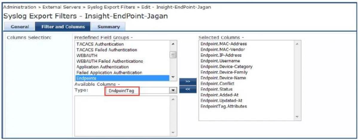
As shown in Figure 591, administrators can select EndpointTag attributes as a column in Syslog Export Filters.
Custom attributes fetched by users and recorded in an endpoint are sent in syslog export filters to the server. When there is a update on endpoints, syslog events are generated.
The data collection interval for Insight logs is -4 to -2 minutes from the current time.
Specify the Syslog Export Filters > Filter and Columns > Insight Logs parameters as described in the following table:
Table 322: Syslog Export Filters > Filter and Columns > Insight Logs Parameters
| Parameter Action/Description | |
| Columns Selection Determine the group of reports that you want to include in the syslog filters. The column selection limits the type of records sent to the syslog filters.NOTE: You can add only the Insight reports that are already created in Insight. You cannot create a new data filter for Insight logs. | |
| Predefined Field Groups | Select the predefined Insight reports that are grouped for addition. |
| Selected Columns | After you select an entry from the Available Columns list, click >> to add the selected entry to the Selected Columns list. Click << to remove an entry from the Selected Columns list. |
Session Logs
This section describes the options if you select Session Logs as the export template in the General tab. On selecting Session Logs, the following options are available:
- Option 1 allows you to choose from pre-defined field groups and to select columns based on the Type.
- Option 2 allows you to create a custom SQL query. You can view a sample template for the custom SQL by clicking the link below the text entry field.

It is recommended to contact support if you choose the option 2. Support can assist you with entering the correct information in this template.
The following figure displays the Syslog Export Filters - Filter and Columns (Session Logs) tab.
Figure 592: Syslog Export Filters - Filter and Columns (Session Logs) Tab
![Administration > External Servers > Syslog Export Filters > Add Syslog Export Filters General Filter and Columns Summary Option 1: For common use -cases, select Data Filter and Columns for export: Data Filter: [All Requests] Modify Add new Data Filter Columns Selection: Predefined Field Groups - Logged in users Failed Authentications RADIUS Accounting TACACS- Administration Available Columns - Type: Common Selected Columns - Common.Aloris Common.Aleris-Present Common.Audit Posture Token Common Auth-Type Common.Connection Status Common.Enforcement-Profiles Common.Error Code Option 2: For advanced use -cases, specify custom SQL query for export : Custom SQL: SELECT "Common.Usage", "Common.Service", "Common.Roles", "Common.Host-MAC-Address", "RADIUS.Acct-Framed-IP-Address", "Common.NAS-IP-Address", "Common.Request-Timestamp", "Common.Alerts" FROM dblink (--DB-CONNECTION-STRING--,'SELECT T1.user_name as 'Common.Usage', T1.service_name as "Common.Service', T3.roles as 'Common.Roles', T1.host_mac as "Common.Host-MAC-Address', T8.framed_in_address as "RADIUS.Acct-Framed-IP-Address". As an example, click here to copy a sample SQL. Back to Syslog Filters Next > Save Cancel](/content/2026/05/842116/images/daa37b4f8df9365577c5744e6207d19098413c5ae86810281246791a74978b8e.jpg)
The following table describes the Syslog Export Filters > Filter and Columns > Session Logs parameters:
Table 323: Syslog Export Filters > Filter and Columns > Insight Logs Parameters
| Parameter | Action/Description |
| Data Filter | Specify the data filter. The data filter limits the type of records sent to the syslog target. |
| Modify/ Add New Data Filter | Modify the selected data filter, or add a new one.Specifying a data filter filters the rows that are sent to the syslog target. You may also select columns that are sent to the syslog target. For more information on adding a data filter, see Adding a Data Filter on page 174. |
| Columns Selection | The column selection limits the type of columns sent to the syslog target.There are predefined field groups, which are column names grouped together for quick addition to the report. For example, Logged in users field group has seven predefined columns. W click Logged in users the seven columns automatically appear in the Selected Columns list.Additional fields are available to add to the reports. You can select the type of attributes (which are the different table columns available in the session database) from the Available Col Type drop down list. Policy Manager populates these column names by extracting the co names from existing sessions in the session database.After you select an entry from the Available Columns list, click >> to add the selected entry to the Selected Columns list.Click << to remove an entry from the Selected Columns list. |
| Custom SQL | Specify custom SQL query for export. This option is for advanced use cases.NOTE: If you choose this option, contact Dell Support atAdministration >Support >Contact Support. Support can assist you with entering the correct information in this template. |
Summary Tab
This section describes the parameters in the Summary tab of the Administration > External Servers > Syslog Export Filters > Add page. The following figure displays the Syslog Export Filters - Summary tab.
Figure 593: Syslog Export Filters - Summary Tab
![General Filter and Columns Summary General: Name: Description: Export Template: Session Logs Syslog Servers: 10.100.9.86 ClearPass Servers: - Filter and Columns: Option 1: For common use-cases, select Data Filter and Columns for export: Data Filter: [Active sessions] Columns Selection: - Option 2: For advanced use-cases, specify custom SQL query for export : Custom SQL: Back to Syslog Filters Next > Save Cancel](/content/2026/05/842116/images/2a6e1ae106dc14cdb681786d2298667f01eafb133798f364080bc66af3c4bf3c.jpg)
The following table describes the Syslog Export Filters - Summary tab parameters:
Table 324: Syslog Export Filters - Summary Tab Parameters
| Parameter Description | |
| General | |
| Name Displays the name of the syslog export filter. | |
| Description Displays the description that provides additional information about the syslog export filter. | |
| Export Template | Displays the template selected as the export template. |
| Syslog Servers | Displays the IP address of the syslog server selected during configuration. |
| W-ClearPass Servers | Displays the IP address of the W-ClearPass servers selected during configuration. |
| Filter and Columns | |
| Data Filter | Displays the data filter selected when configuring option 1 in theFilter and Columnstab. |
| Columns Selection | Displays the predefined field groups and available columns type selected when configurir option 1 in theFilter and Columnstab. |
| Custom SQL | Displays the SQL query selected when configuring option 2 in theFilter and Columnstab. |
Importing a Syslog Filter
To import a syslog target:
- Navigate to Administration > External Servers > Syslog Export Filters.
- Click the Import link on the top right section of the page. Enter the details based on Table 325.
- Click Import.
The following figure displays the Import from file pop-up:
Figure 594: Import from file Pop-up
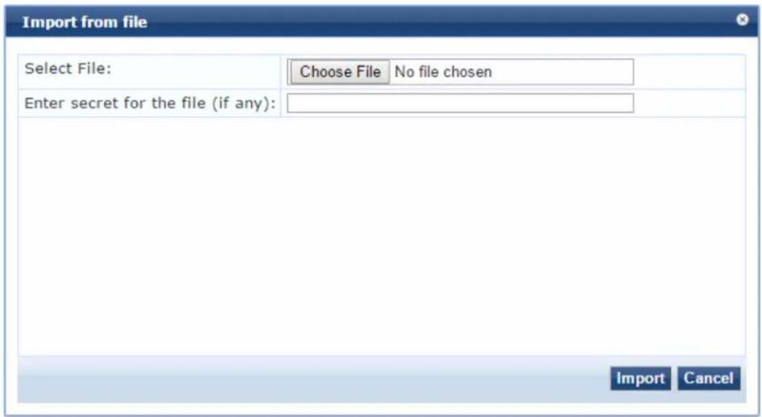
The following table describes the Import from file parameters:
Table 325: Import from file Parameters
| Parameter Description | |
| Select File Browse to the Syslog | Filter configuration file to be imported. |
| Enter secret for the file (if any) | If the file was exported with a secret key for encryption, enter the same key here. |
Exporting All Syslog Filter
To export all syslog filters:
- Navigate to Administration > External Servers > Syslog Export Filters.
- Click the Export All link on the top right section of the page. Enter the details based on Table 326.
- Click Export.
- Enter the XML file name in the Save As dialog box.
- Click Save.
The following figure displays the Export to file pop-up:
Figure 595: Export to file Pop-up
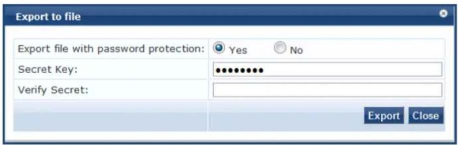
The following table describes the Export to file parameters:
Table 326: Export to file Parameters
| Parameter Description | |
| Export file with password protection | Choose Yes to export the file with password protection. |
| Secret Key Enter the secret key. | |
| Verify Secret Re-enter the secret key. |
Exporting a Syslog Filter
To export a syslog filter:
- Navigate to Administration > External Servers > Syslog Export Filters.
- Select the Host Address from the list of check boxes and click Export. Enter the details based on Table 327.
- Enter the name of the XML file in the Save As dialog.
- Click Save.
The following figure displays the Export to file pop-up:
Figure 596: Export to file Pop-up
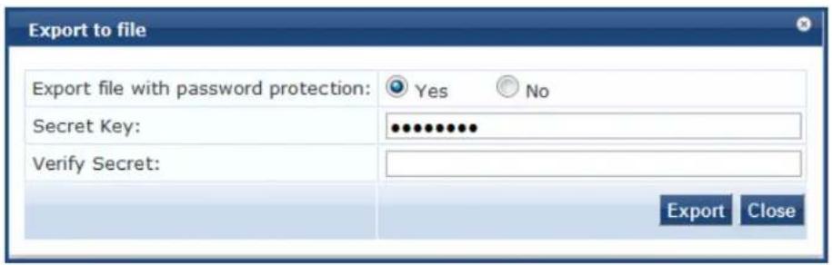
The following table describes the Export to file parameters:
Table 327: Export to file Parameters
| Parameter Description | |
| Export file with password protection | Choose Yes to export the file with password protection. |
| Secret Key Enter the secret key. | |
| Verify Secret Re-enter the secret key. |
Deleting a Syslog Filter
To delete a syslog filter:
- Navigate to Administration > External Servers > Syslog Export Filters.
- Click the check box next to the syslog filter entry and click Delete.
- Click Yes.
Messaging Setup
This section provides the following information:
- Configuring Messaging
- Sending a Test Email Message
- Sending a Test SMS Message
W-ClearPass messaging setup provides an interface to configure the Simple Mail Transfer Protocol (SMTP) server for email and SMS notifications.
Configuring Messaging
To configure messaging:
- Navigate to Administration > External Servers > Messaging Setup.
The Messaging > SMTP Server page opens.
Figure 597: Messaging > SMTP Server Page
Administration > External Servers > Messaging Setup
Messaging
Configure SMTP mail server for email notifications:
+ Configure SMS Gateway
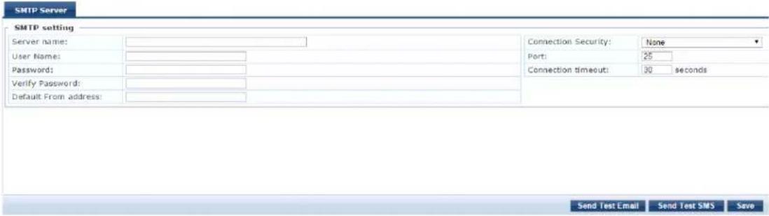
- To configure a new SMS gateway using the W-ClearPass Guest portal, click the Configure SMS Gateway link at the top right section of the page.
The following table describes the Messaging > SMTP Server page parameters:
Table 328: Messaging > SMTP Server Page Parameters
| Parameter Action/Description | |
| Server name 1. Enter | the Fully Qualified Domain Name (FQDN) or the IP address of the SMTP server. |
| User Name 2. Enter | the username if your email server requires authentication for sending email messages. |
| Password | 3. Enter the password for the specified username, then verify the password. |
| Default From address | 4. Enter the email address that must to be displayed as the sender's address in the message. |
| Connection Security | 5. To establish the communication with the SMTP server, select from one of the following options:None: Select this option to disable secure communication with the server.SSL: Select this option to have a Secured Socket Layer communication with the server.Start TLS: Select this option to have a Transport Layer Security communication with the server. |
| Port | 6. Enter the TCP port number that the SNMP server listens on.The default value of the port is 25. |
| Connection timeout | 7. Enter the timeout value for connection to the SMTP server (in seconds).The default value is 30 seconds. |
Sending a Test Email Message
To send a test mail message to the preferred email address:
- Click Send Test Email.
The Send Test Email dialog opens.
Figure 598: Send Test Email Dialog
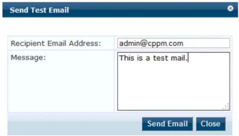
- Recipient Email Address: Enter the email address of the recipient.
- Message: Enter the test message.
- Click Send Email.
Sending a Test SMS Message
To send a test SMS message to the preferred email address:
- Click Send Test SMS.
The Send Test SMS dialog opens.
Figure 599: Send Test SMS Dialog
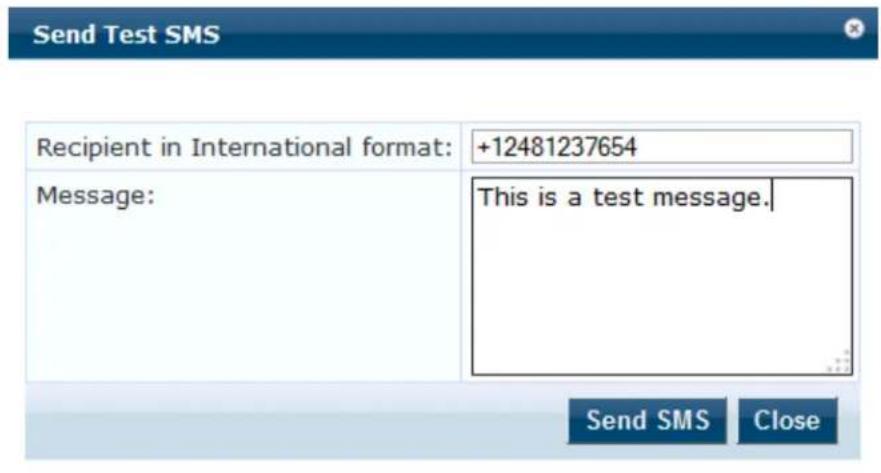
- Recipient in International format: Enter the mobile phone number of the recipient in international format.
The recipient's mobile number must be entered in the international format consisting of a + sign, followed by the country code and the mobile phone number (without the first '0' of the number).
- Message: Enter the test message.
- Click Send SMS.
Endpoint Context Servers
This section describes the following topics:
- Introduction
• Endpoint Context Servers Page - Adding an Endpoint Context Server
- Importing an Endpoint Context Server
- Exporting All Endpoint Context Servers
- Modifying an Endpoint Context Server
- Polling an Endpoint Context Server
• Deleting an Endpoint Context Server
For related information, see:
- Configuring Endpoint Context Server Actions on page 614
- Adding Vendor-Specific Endpoint Context Servers on page 619
• Endpoint Information Collectors on page 452
Introduction
The mobile device management (MDM) platforms run on MDM servers. These servers provision mobile data to configure connectivity settings, enforce security policies, restore lost data, and other administrative services. Information gathered from mobile devices can include policy breaches, data consumption, and existing configuration settings.
Endpoint Context Servers Page
- To access the Endpoint Context Servers page, navigate to Administration > External Servers > Endpoint Context Servers.
The Endpoint Context Servers page appears:
Figure 600: Endpoint Context Servers Page
Administration » External Servers » Endpoint Context Servers
Endpoint Context Servers

The following table describes the Endpoint Context Servers categories:
Table 329: Endpoint Context Server Categories
| Parameter Description | |
| Server Name Displays the name of the endpoint context server. | |
| Server Type Displays the type of the endpoint context server. | |
| Status | Displays the status of the endpoint context server: Enabled or Disabled. For non-MDM servers, the status is always displayed as Disabled. |
Adding an Endpoint Context Server
To add an endpoint context server:
- Navigate to Administration > External Servers > Endpoint Context Servers.
- Click the Add link at the top right section of the page.
The Add Endpoint Context Server dialog opens.
The fields and parameters that are displayed in the Add Endpoint Context Server dialog vary depending on which Server Type you select (see Select Server Type in Table 330).
Figure 601: Adding an Endpoint Context Server
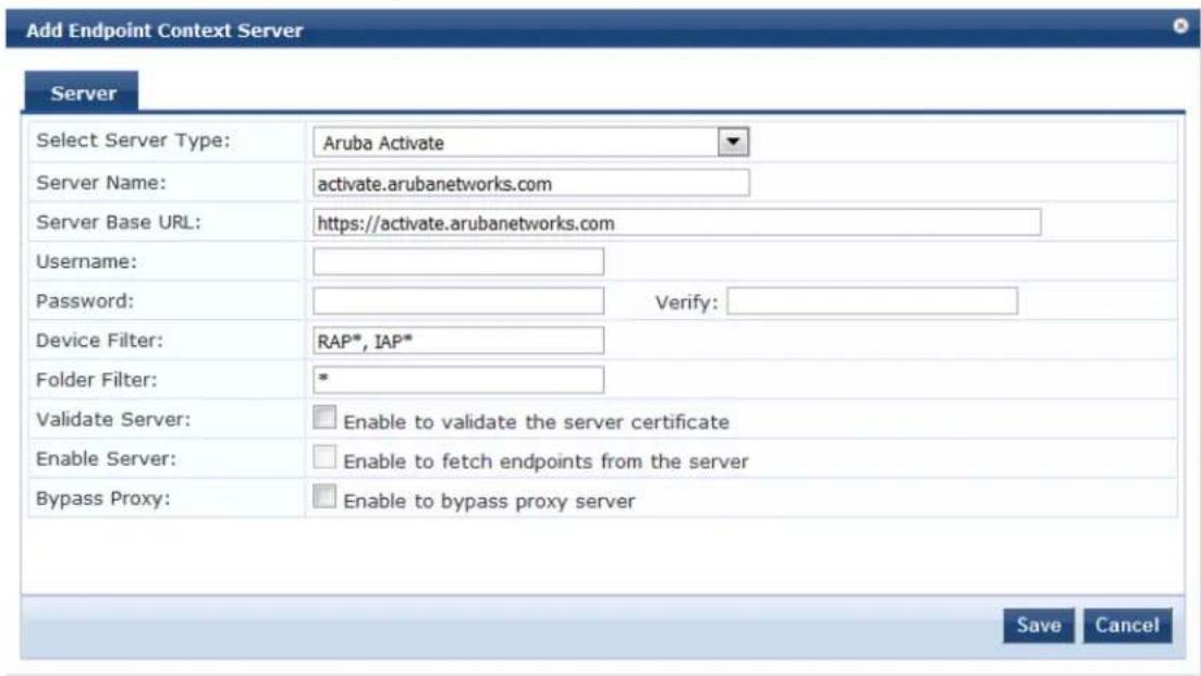
- In the Add Endpoint Context Server dialog, specify the parameters as described in Table 330.
- Click Save.
Table 330 describes the Add Endpoint Context Servers parameters:
Table 330: Add Endpoint Context Server Parameters
| Parameter Description | |
| Select Server Type | 1. Choose one of the Server Types (endpoint context server vendors) from the following options.The Server Type you select determines the configuration parameters.■ AirWatch■ Aruba Activate■ AirWave■ Google Admin Console■ Generic HTTP■ JAMF■ Juniper SRX■ MaaS360■ MobileIron■ Palo Alto Networks Firewall■ Palo Alto Networks Panorama■ SAP Afaria■ SOTI■ XenMobileNOTE: You can add more than one endpoint context server of the same type. |
| Server Name 2. Enter the name of the server or host. | |
| Server Base URL | 3. Enter the full URL for the server.The default is the name you entered above with "https://" prepended. You can app custom port, such as for an MDM server:https://yourserver.yourcompany.com:customerportnumber. |
| Username | 4. Enter the username. |
| Password | 5. Enter the password of the server or host, then verify the password. |
| API Key | 6. Enter the API key that was provided by the vendor, then verify the API key.This field is not displayed for all endpoint context servers. |
| Validate Server | 7. Select the Enable to validate the server certificate check box to validate.By default, this field is disabled.NOTE: Checking this option enables the Certificate tab. |
| Enable Server | 8. Select the Enable to fetch endpoints from the server check box to enable the endpoint context server.By default, this field is disabled.NOTE: The Bypass Proxy field is enabled only if you enable this field. Checking this option enables the Poll Status tab. |
| Bypass Proxy | 9. Select the Enable to bypass proxy server check box to bypass the proxy server.By default, this field is disabled. You must enable the Enable Server parameter to enable this field.You can select this option to specify that the endpoint context server should not be configured proxy settings (if a proxy is used). W-ClearPass then bypasses the proxy server for functions such MDM API, Endpoint Context Server Actions, and Generic outbound enforcement.NOTE: When this field is enabled, the proxy servers configured in the Administration > Server Manager > Server Configuration > Service Parameters tab > W-ClearPass System Services service page will be bypassed. The server discovery occurs without a issues even when the proxy servers are bypassed. |
Importing an Endpoint Context Server
To import an endpoint context server:
- Navigate to Administration > External Servers > Endpoint Context Servers.
- Click the Import link on the top right section of the page.
- Enter the parameters based on Table 331.
- Click Import.
Figure 602 displays the Import from File dialog:
Figure 602: Import from File Dialog
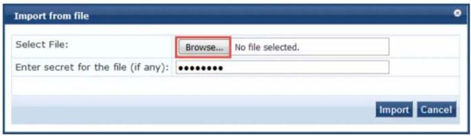
The following table describes the Import from file parameters:
Table 331: Import from File Dialog Parameters
| Parameter Description | |
| Select File Browse to the Endpoint Context Server configuration file to be imported. | |
| Enter secret for the file (if any) | If the file was exported with a secret key for encryption, enter the same key here. |
Exporting All Endpoint Context Servers
To export all endpoint context servers:
- Navigate to Administration > External Servers > Endpoint Context Servers.
- Click the Export All link on the top right section of the page.
The Export to File dialog opens.
Figure 603: Export to File Dialog
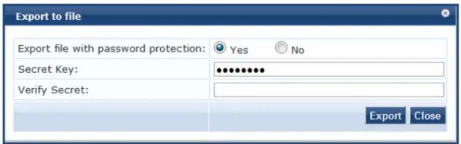
- Enter the parameters as described in Table 332.
- Click Export.
- Enter the XML file name in the Save As dialog box.
- Click Save.
Table 332 describes the Export to file parameters:
Table 332: Export to File Dialog Parameters
| Parameter Action/Description | |
| Export file with password protection | 1. To export the file with password protection, choose Yes. |
| Secret Key 2. Enter the secret key. | |
| Verify Secret 3. Re-enter the secret key. | |
Modifying an Endpoint Context Server
To modify an endpoint context server:
- Navigate to Administration > External Servers > Endpoint Context Servers.
- In the Endpoint Context Servers main page, click the desired server name entry.
- In the Modify Endpoint Context Server dialog, enter the details based on specific Server Type (vendor link) listed in Table 330, "Add Endpoint Context Server Parameters."
- Click Update.
The tabs that appear when you add or modify an endpoint context server vary depending on the type (vendor) of endpoint context server selected.

Server Tab
Use the Server tab to modify the server name, server base URL, and API key.
You can also use this dialog to validate the server certificate and to bypass proxy servers. The following displays the Modify Endpoint Context Server > Server dialog:
Figure 604: Modify Endpoint Context Server > Server Dialog
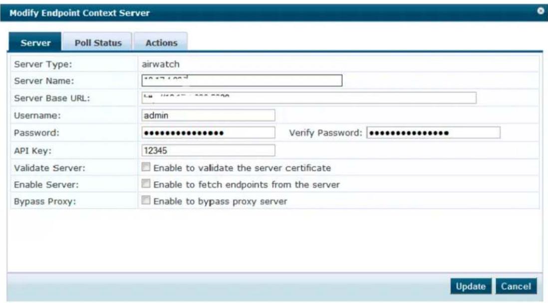
The following table describes the Modify Endpoint Context Server > Server parameters:
Table 333: Modify Endpoint Context Server > Server Parameters
| Parameter Action | Description |
| Server Type The Server Type cannot be modified. | |
| Server Name 1. Enter the name of the server or host. | |
| Server Base URL 2. Enter the full URL for the server.The default is the name you entered above with "https://" prepended.You can append a custom port, such as for an MDM server:https://yourserver.yourcompany.com:customerportnumber | |
| Username 3. Enter the username of the server or host. | |
| Password 4. Enter the password of the server or host, then verify the password. | |
| Validate Server | 5. Enable this check box to validate the server certificate.By default, this field is disabled.NOTE: Checking this option enables the Certificate tab. |
| Bypass Proxy | 6. Select the Enable to bypass proxy server check box to bypass the proxy server.By default, this field is disabled. You must enable the Enable Server parameter to enable this field.You can select this option to specify that the endpoint context server should no the configured proxy settings (if a proxy is used). W-ClearPass then bypasses the server for functions such MDM API, Endpoint Context Server Actions, and Generic HTTP outbound enforcement.NOTE: When this field is enabled, the proxy servers configured in the Administration > Server Manager > Server Configuration > Service Parameters tab > W-ClearPass System Services service page will be bypassed. The server discovery occurs without any issues even when the proxy servers are bypassed. |
Actions Tab
Use the Actions tab to view the server action that is performed on endpoints and their description. The fields and parameters that are displayed in the Actions dialog vary depending on which Server Type you select (see the Select Server Type vendor links listed in Table 330, "Add Endpoint Context Server Parameters").
For more information about endpoint context server actions configuration, see Configuring Endpoint Context Server Actions on page 614.
The following figure displays an example of the Modify Endpoint Context Server > Actions tab:
Figure 605: Modify Endpoint Context Server > Actions Tab
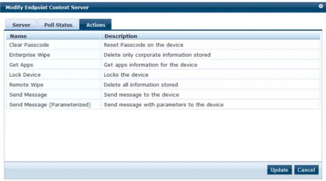
Polling an Endpoint Context Server
To poll an endpoint context server:
You can poll only one server at a time. You cannot poll multiple server entries. Also, you can only poll MDM-type servers.
- Navigate to Administration > External Servers > Endpoint Context Servers.
- In the Endpoint Context Servers main page, click the check box next to the server name entry.
Figure 606: Selecting the Trigger Poll Option
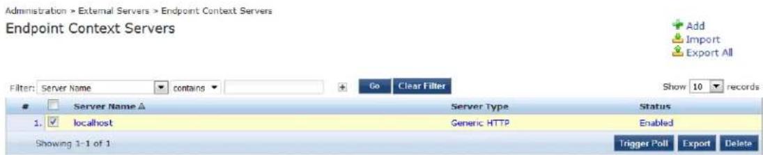
3. Click Trigger Poll.
Deleting an Endpoint Context Server
Deleting an endpoint context server removes the configuration information from the Policy Manager server. To save the endpoint context server configuration prior to deleting the server:
- Before you delete the endpoint context server, export the server.
- Save the configuration so that you can import it in future if necessary.
To delete an endpoint context server:
- Navigate to Administration > External Servers > Endpoint Context Servers.
- Select the check box next to the server name entry, then click Delete.
- To confirm the delete operation, click Yes.

Configuring Endpoint Context Server Actions
This section contains the following information:
• Filtering an Endpoint Context Server Action Report
- Configuring Endpoint Context Server Actions
- Adding machine-os and host-type Endpoint Attributes
Filtering an Endpoint Context Server Action Report
Use the Filter controls to configure a search for a subset of Endpoint Context Server Action items.
To filter an endpoint context server action report:
- Navigate to Administration > Dictionaries > Context Server Actions.
The Endpoint Context Server Actions page opens (see Figure 607). - From the Filter drop-down, select a filter: ServerType, Action Name, or HTTP method.
- To add up to four new search fields, click the Plus icon.
-
Select a search argument.
The search arguments are limited to contains or equals. -
Click Go.
Configuring Endpoint Context Server Actions
Use the Endpoint Context Server Actions page to configure actions that are performed on endpoints, such as locking a device, triggering a remote, or enterprise wipe, and so on.
The Context Server Actions page displays the report that shows information about all configured Endpoint Context Server Actions.
To configure endpoint context server actions:
- Navigate to Administration > Dictionaries > Context Server Actions > Endpoint Context Server Actions page.
Figure 607 displays an example of the Endpoint Context Server Actions page:
Figure 607: Endpoint Context Server Actions Page
Administration » Dictionaries » Context Server Actions
Endpoint Context Server Actions
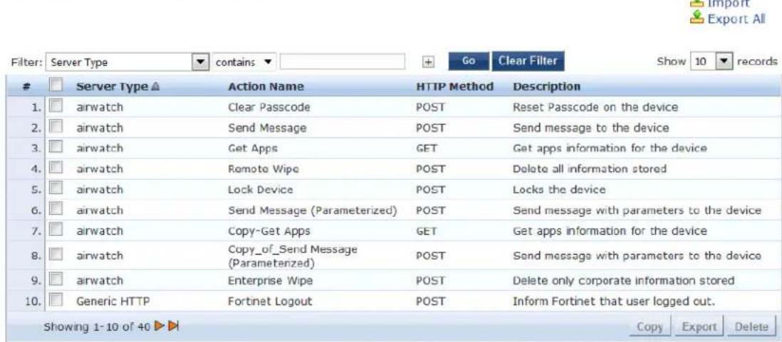
Table 334 describes the Endpoint Context Server Actions settings:
Table 334: Endpoint Context Server Actions Page Settings
| Settings Description | |
| Server Type Indicates the server type configured when the server action was configured. | |
| Action Name Indicates the name of the context server action. The available server actions vary depending what Server Type is specified. | |
| HTTP Method Specifies the HTTP method selected when the server action was configured. | |
| Description Provides the description of the server action. |
- From the Endpoint Context Server Actions page, click a row in the report.
The Endpoint Content Server Details dialog opens.
Figure 608: Endpoint Context Server Details Dialog
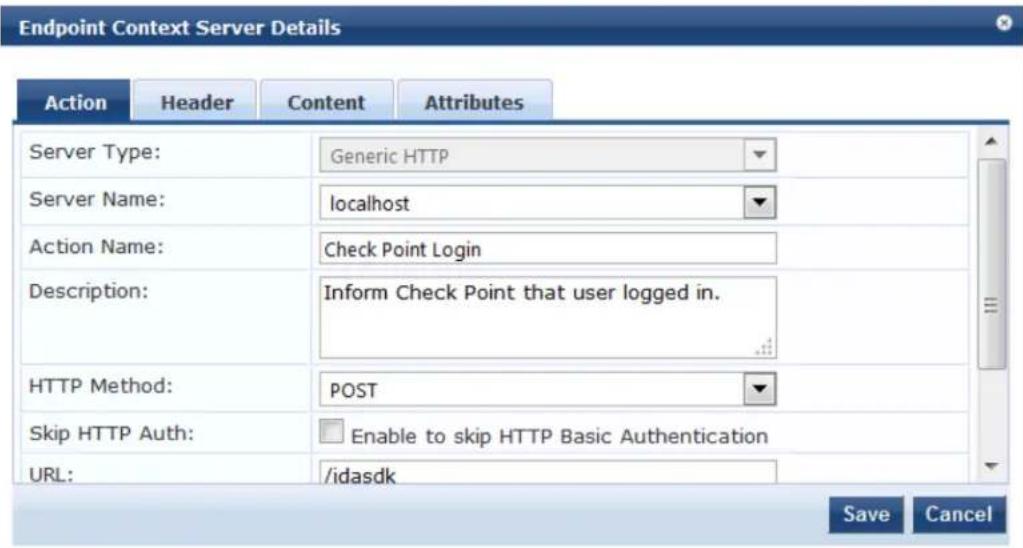
- Click a tab to view details about the selected Endpoint Context Server action.
- Make any changes required, then click Save.
Action Tab Parameters
Use the Action tab to specify the server type, action name, HTTP method, and URL for the specified HTTP method.
Table 335 describes the the Action tab parameters.
Table 335: Action Parameters—Endpoint Context Server Details
| Parameter | Description |
| Server Type | Specifies the server type configured when the server action was configured. You can select the server type from the drop-down list. |
| Server Name | Lists the context servers specific to the server type selected in the Server Type field. This field is visible only if you selected the service type Generic HTTP. |
| Action Name | Specifies the name of the action configured. |
| Description | Provides additional information about the action specified. |
| HTTP Method | Specifies the HTTP method selected when the server action was configured. |
| Skip HTTP Auth | Select this check box to disable the HTTP basic authentication for endpoint context server actions. This exposes the context server attributes to be used in context server actions. |
| URL Indicates | the URL for the selected HTTP method. |
Header Tab Parameters
Use the Header tab to specify the key-value pairs to be included in the HTTP header.
Figure 609: Header Tab—Endpoint Context Server Details
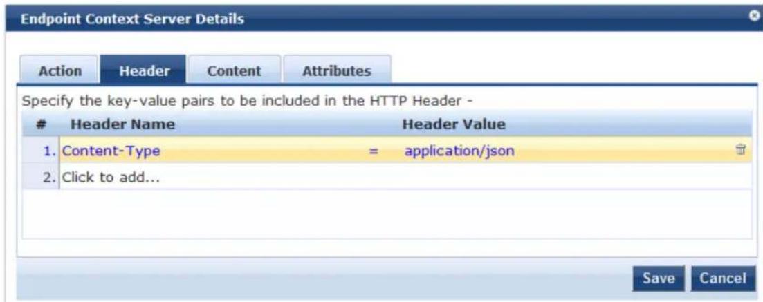
Table 336 describes the Endpoint Context Server Details—Header parameters:
Table 336: Header Parameters—Endpoint Context Server Details
| Parameter Description | |
| Header Name | Specify the name of the header to be included in the HTTP header. |
| Header Value | Specify the value of the header specific to the name to be included in the HTTP header. |
Content Tab
Use the Content tab to specify a content type and add non-default context server attributes (see Figure 610). The information in the Content window is the template of what will be posted to the server. The fields preceded by the % sign are replaced with their corresponding values.
Figure 610: Content Tab—Endpoint Context Server Details
![Endpoint Context Server Details Action Header Content Attributes Content-Type: JSON Content: {"shared_secret": "%{shared_secret}", "request": [{"command":"add_user","username":"%{name}", "ip":"%{ip}", "machine_name":"%{machine}", "domain":"% {domain}", "identity_source":"Aruba ClearPass Policy Manager", "timeout":"% {timeout}, "fetch_roles":1,"fetch_groups":1}]} Save Cancel](/content/2026/05/842116/images/904d4909899ffda1ddd951c49677a171588805b8c2d5ca9c1ed30b76a80a6d16.jpg)
Table 337 describes the Endpoint Context Server Details—Content parameters:
Table 337: Content Parameters—Endpoint Context Server Details
| Parameter Action/Description | |
| Content-Type | Specify the type of the content. Select from the following options:CUSTOMHTMLJSONPLAINXML |
| Content Specify the content.For example, { "mac": "%{Connection:Client-Mac-Address-NoDelim}","nmap": {"device": "%{DEVICECATEGORY}}}. | |
For related information, see Adding machine-os and host-type Endpoint Attributes on page 618).
Attributes Tab Parameters
Use the Attributes tab to specify the mapping for attributes used in the content to parameterized values from the request.
Figure 611: Attributes Tab—Endpoint Context Server Details
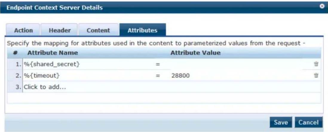
Table 338 describes the Endpoint Context Server Details—Attributes parameters:
Table 338: Attributes Parameters—Endpoint Context Server Details
| Parameter Description | |
| Attribute Name | Enter attribute names and assign values to those names. These name/value pairs are inclu in context server actions. |
| Attribute Value | Enter the value for the selected name in the Attribute Name field. |
Adding machine-os and host-type Endpoint Attributes
To be able to indicate the entire OS family (Android, Windows, Linux, etc.) and the type of device (iPad, etc.), you can add the machine-os Device Family attribute and the host-type Device Type attribute to the default set of endpoint context attributes provided in the Content window:
To add the machine-os and host-type endpoint context attributes:
-
Navigate to Administration > Dictionaries > Context Server Actions.
The Endpoint Context Server Actions page opens. -
Scroll to and select the Generic HTTP/Check Point Login server action.
Figure 612: Selecting the Check Point Login Server Action
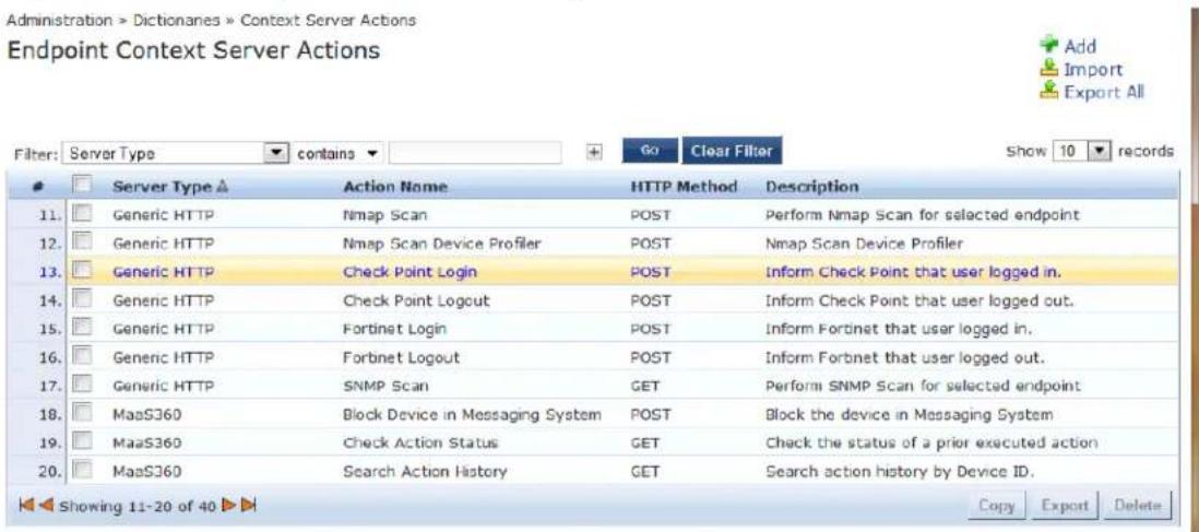
The Endpoint Context Server Details dialog opens.
- Select the Content tab (see Figure 613).
- In the Content field, add the following attributes (see Figure 613):
■ "machine-os":" %{device_family}"
■ "host-type":"%{device_type}"
Figure 613: Adding Endpoint Context Server Attributes
![Endpoint Context Server Details Action Header Content Attributes Content-Type: JSON Content: {"shared_secret": "%{shared_secret}", "request": [{"command":"add_user", "username":"%{name}", "ip":"%{ip}", "machine_name":"%{machine}", "machine-os":" %{device_family}", "host-type":"%{device_type}", "domain":"% {domain}", "identity_source":"Aruba ClearPass Policy Manager", "timeout":"%{timeout}, "fetch_roles":1, "fetch_groups":1}]} Save Cancel](/content/2026/05/842116/images/55c0b3f46725026bfa63cd38e453bdfa91a1af05f69922fd0d8707be0141533a.jpg)
- Click Save.
You receive the following message:
Context Server Action "Check Point Login (Generic HTTP)" updated successfully
Adding Vendor-Specific Endpoint Context Servers
This section provides information on the following topics:
- Adding an AirWatch Endpoint Context Server
-
Adding an AirWave Endpoint Context Server
-
Adding an Aruba Activate Endpoint Context Server
- Adding a ClearPass Cloud Proxy Endpoint Context Server
- Adding a Generic HTTP Endpoint Context Server
- Adding a Google Admin Console Endpoint Context Server
• Integrating W-ClearPass with Infoblox - Adding a JAMF Endpoint Context Server
• Integrating W-ClearPass with Juniper Networks SRX - Adding a MaaS360 Endpoint Context Server
- Adding a MobileIron Endpoint Context Server
- Adding a Palo Alto Networks Firewall Endpoint Context Server
- Adding a Palo Alto Networks Panorama Endpoint Context Server
- Adding an SAP Afaria Endpoint Context Server
- Adding a SOTI Endpoint Context Server
- Adding a XenMobile Endpoint Context Server
Adding an AirWatch Endpoint Context Server
Consult Airwatch's documentation for information about the parameters that you must enter to configure endpoint.
To add an Airwatch Endpoint Context Server:
- Navigate to Administration > External Servers > Endpoint Context Servers.
The Endpoint Context Servers page opens. - Click Add.
The Add Endpoint Context Server page opens. This dialog opens in the Server tab. - From the Select Server Type drop-down, select airwatch.
Server Tab
The Airwatch Add Endpoint Context Server > Server page opens:
Figure 614: Adding an Airwatch Endpoint Context Server > Server Page
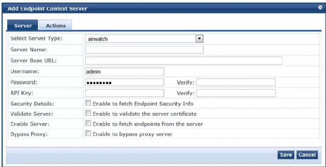
Specify the Add Airwatch Endpoint Context Server > Server parameters as described in the following table:
Table 339: Adding an Airwatch Endpoint Context Server > Server Tab Parameters
| Parameter Action/Description | |
| Select Server Type Choose AirWatch from the drop-down list. | |
| Server Name Enter a | valid server name. You can enter an IP address or a hostname. |
| Server Base URL Enter | the full URL for the server. You can append a custom port, such as for an MDM server: https://yourserver.yourcompany.com:customerportnumber |
| Username Enter the user name. | |
| Password Enter and verify the password. | |
| Verify Password | |
| API Key Enter the API | key that is provided by the vendor. |
| Security Details Enable to fetch endpoint security information. | |
| Validate Server | Enable to validate the server certificate. Checking this option activates the Certificate tab. |
| Enable Server | Select the Enable to fetch endpoints from the server check box to enable the endpoint context server. By default, this field is disabled. The Bypass Proxy field will be enabled only if you enable this field. |
| Bypass Proxy | Select the Enable to bypass proxy server check box to bypass the proxy server. When this field is enabled, the proxy servers configured in the Administration > Server Manager > Server Configuration > Service Parameters tab > ClearPass system services service page will be bypassed. The server discovery occurs without any issues even when the proxy servers are bypassed. By default, this field is disabled. You must enable the Enable Server fiel enable this field. |
Actions Tab
The following figure displays the Airwatch Add Endpoint Context Server > Actions page:
Figure 615: Adding an Airwatch Endpoint Context Server > Actions Page
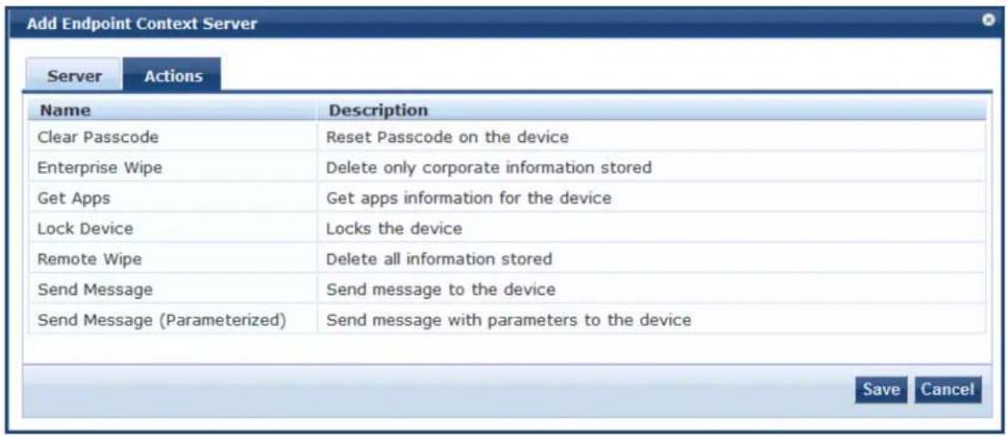
Specify the Airwatch Add Endpoint Context Server > Actions parameters as described in the following table:
Table 340: Adding an Airwatch Endpoint Context Server > Actions Tab Parameters
| Parameter Action/Description | |
| Clear Passcode Reset passcode on the device. | |
| Enterprise Wipe Delete only stored corporate information. | |
| Get Apps Get application information for the device. | |
| Lock Device Lock the associated device. | |
| Remote Wipe | Delete all stored information. |
| Send Message | Send message to the device. |
| Send Message (Parameterized) | Send message with parameters to the device. |

The ComplianceStatus attribute from Airwatch is mapped to the Compliance attribute in the Endpoint dictionary. The available Compliance attributes are: NotAvailable, NonCompliant, or Compliant.
Adding an AirWave Endpoint Context Server
For more information about AirWave, refer to Dell AirWave documentation.
To add an AirWave Endpoint Context Server:
- Navigate to Administration > External Servers > Endpoint Context Servers.
The Endpoint Context Servers page opens.
- Click Add.
The Add Endpoint Context Server dialog opens.
- From the Select Server Type drop-down, select AirWave.
The following dialog is displayed:
Figure 616: Add an AirWave Endpoint Context Server > Server Dialog
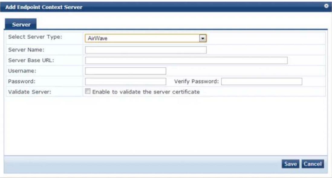

You can add multiple endpoint context servers of the same type.
- Enter the appropriate values for each of the AirWave Add Endpoint Context Server parameters describ Table 341.
- When satisfied with the settings, click Save.
Table 341: Adding an AirWave Endpoint Context Server > Server Parameters
| Parameter Action/Description | |
| Select Server Type | 1. Choose AirWave from the Select Server Type drop-down list. |
| Server Name 2. Enter a valid server name. You can enter an IP address or hostname. | |
| Server Base URL 3. Enter the full URL for the AirWave server.You can append a custom port, such as for an MDM server:https://yourserver.yourcompany.com:customerportnumber | |
| Username 4. Enter the username for the AirWave server. | |
| Password 5. Enter the password for the server, then verify the password. | |
| Verify Password | |
| Validate Server | 6. Enable Validate Server to validate the server certificate.Checking this option enables the Certificate tab. |
| Bypass Proxy 7. Enable Bypass Proxy to bypass the proxy server. | |
Adding an Aruba Activate Endpoint Context Server
For more information about Activate, refer to Aruba Activate documentation.
Server Tab
The following figure displays the Aruba Activate Add Endpoint Context Server > Server tab:
Figure 617: Adding an Aruba Activate Endpoint Context Server
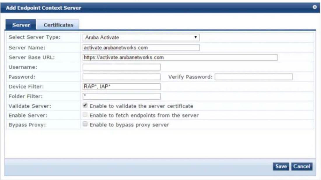
The following table describes the Aruba Activate Add Endpoint Context Server > Server parameters:
Table 342: Adding an Aruba Activate Endpoint Context Server > Server Parameters
| Parameter | Action/Description |
| Select Server Type | 1. Choose Aruba Activate from the Select Server Type drop-down list. |
| Server Name | 2. Enter a valid server name. You can enter an IP address or a hostname. |
| Server Base URL | 3. Enter the complete URL for the Aruba Activate server.You can append a custom port, such as for an MDM server:https://yourserver.yourcompany.com:customerportnumber |
| Parameter Action/Description | |
| Username 4. Enter | the username for the Aruba Activate server. |
| Password 5. Enter | the password, then verify the password. |
| Verify Password | |
| Device Filter | The Device Filter field is populated with a default regular expression to retrieve only the Remote AP (RAP) and Instant AP (IAP) information. |
| Folder Filter The Folder Filter field is set to "*" by default. | |
| Disable Stale Enpoints | 6. To disable stale endpoints in the Endpoint database, enable this option. |
| Validate Server | 7. Enable Validate Server to validate the server certificate.Checking this option enables the Certificate tab. For information on certificate configuration, see Certificates Tab on page 625. |
| Enable Server | 8. Enable Enable Server to fetch endpoints from the server. |
| Bypass Proxy | 9. Enable Bypass Proxy to bypass the proxy server. |
| 10. To save your configuration changes, click Save. | |
Certificates Tab
The following figure displays the Aruba Activate Add Endpoint Context Server > Certificates tab:
Figure 618: Adding an Aruba Activate Endpoint Context Server > Certificates
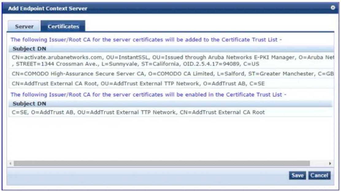
Adding a ClearPass Cloud Proxy Endpoint Context Server
The Cloud Proxy is a virtual instance configured in the cloud. This multi-tenant and single instance serve multiple customers having many W-ClearPass server nodes.
Once configured, the W-ClearPass Policy Manager server establishes a Cloud Tunnel to the Cloud Proxy instance given the credentials and Domain. The Domain is required as an identifier to indicate which Clo Tunnel is applicable for which customer.
You can select individual W-ClearPass nodes in the cluster to establish the Cloud Tunnel, rather than all the W-ClearPass cluster.
Figure 619: Add ClearPass Cloud Proxy Endpoint Context Server Dialog
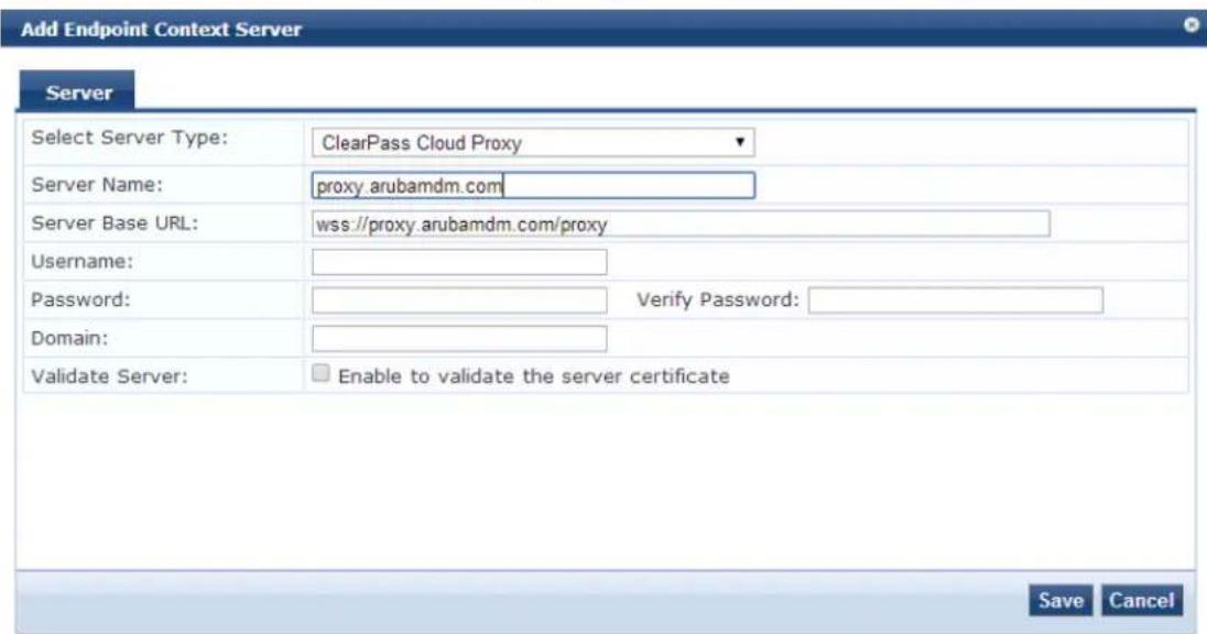
Specify the ClearPass Cloud Proxy Endpoint parameters as described in the following table:
Table 343: Add ClearPass Cloud Proxy Endpoint Context Server Parameters
| Parameter | Action/Description |
| Select Server Type | Select ClearPass Cloud Proxy. |
| Server Name | Enter the host name of the cloud instance that will proxy all requests directed to the W-ClearPass server in the enterprise. |
| Server Base URL | Enter the full URL for the server. The default URL is the name you entered above with https://prepended.You can append a custom port, such as for an MDM (Mobile Device Management) server:https://yourserver.yourcompany.com:customerportnumber |
| Username Enter the username.Usage/Password-based authentication is used when you set up a cloud tunnel from the W-ClearPass server to the Cloud Proxy instance. | |
| Password Verify | Enter the password, then verify it. |
| Password | |
| Domain Specify a domain identifier used to determine the specific Cloud Tunnel to which the request must be sent by the Cloud Proxy. | |
| Validate Server | Click the Validate Server check box to enable validation of the server certificate. |
Adding a Google Admin Console Endpoint Context Server
Consult Google Developer documentation for information about the parameters that you must enter to configure this endpoint.
Server Tab
The following figure displays the Add Endpoint Context Server - Server (Google Admin Console) tab:
Figure 620: Add Endpoint Context Server - Server (Google Admin Console) Tab
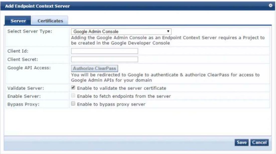

You can add more than one endpoint context server of the same type. For example, you can add more than one AirWatch endpoint context server.
The following table describes the Add Endpoint Context Server - Server (Google Admin Console) tab parameters:
Table 344: Add Endpoint Context Server - Server (Google Admin Console) Tab Parameters
| Parameter Description | |
| Select Server Type Choose Google Admin Console from the drop-down list. | |
| Client Id Enter the client ID. For example,9169879216kpl50kxuaq6q6qqwe0i.apps.googleusercontent.com. | |
| Client Secret Enter the client secret. For example,gMcfg342ePaKgx1ZIXK. | |
| Google API Access Authenticate and authorize W-ClearPass for access to Google Admin APIs for your domain. | |
| Validate Server | Enable to validate the server certificate. Checking this option enables the Certificate tab.For more information on certificate, see Certificates Tab on page 628. |
| Enable Server Enable | this field to fetch endpoints from the server. |
| Bypass Proxy | Select the Enable to bypass proxy server check box to bypass the proxy server. When this field is enabled, the proxy servers configured in the Administration >Server Manager >Server Configuration >Service Parameters tab >ClearPass system services service page will be bypassed. The server discovery occurs without any issue even when the proxy servers are bypassed. By default, this field is disabled. |
Certificates Tab
The following figure displays the Add Endpoint Context Server - Certificates (Google Admin Console) tab:
Figure 621: Add Endpoint Context Server - Certificates (Google Admin Console) Tab
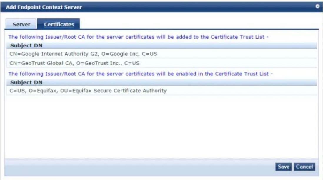
Adding a Generic HTTP Endpoint Context Server
The following figure displays the Generic HTTP Add Endpoint Context Server > Server tab:
Figure 622: Adding a Generic HTTP Endpoint Context Server
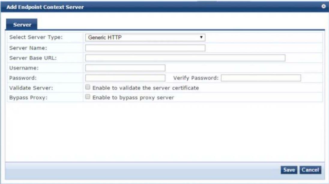

You can add more than one endpoint context server of the same type. For example, you can add more than one AirWatch endpoint context server.
The following table describes the Generic HTTP Add Endpoint Context Server > Server parameters:
Table 345: Add Endpoint Context Server - Server (Generic HTTP) Tab Parameters
| Parameter Action/Description | |
| Select Server Type | 1. Choose Generic HTTP from the Select Server Type drop-down list. |
| Server Name 2. Enter a valid server name. You can enter an IP address or a hostname. | |
| Server Base URL | 3. Enter the complete URL for the server.You can append a custom port, such as for an MDM server:https://yourserver.yourcompany.com:customerportnumber |
| Username | 4. Enter the username for the server. |
| Password | 5. Enter the password, then verify the password. |
| Verify Password | |
| Validate Server | 6. Enable Validate Server to validate the server certificate.Checking this option enables the Certificate tab. |
| Bypass Proxy 7. Enable Bypass Proxy to bypass the proxy server. | |
| 8. Click Save to save your changes. | |
Integrating W-ClearPass with Infoblox
This section provides the following information:
- Adding an Infoblox Endpoint Context Server
- Adding a Context Server Action to the Infoblox Server
- Creating an Infoblox Enforcement Profile
- Configuring an Infoblox RADIUS Enforcement Profile
- Creating an Infoblox Enforcement Policy
• Defining an Infoblox Service
• Authenticating External Devices Against the Infoblox Service - Creating a Filter to Accept Information from the W-ClearPass Server
Infoblox is a server that provides a host of services, such as DNS, DHCP, and IPAM (IP address manager). Infoblox provides a DHCP management system that issues IP addresses to externally authenticated device and also maintains a MAC address context associated with the newly allocated IP address.
Integrating W-ClearPass with Infoblox typically tags the username context, as well as the external device authenticated, along with its respective MAC address, which further simplifies IP address management on Infoblox side.
This section describes the configurations that you must make on the W-ClearPass server in order for the W-ClearPass server to send data to an Infoblox server.
Adding an Infoblox Endpoint Context Server
To add an Infloblox endpoint context server:
- Navigate to Administration > External Servers > Endpoint Context Servers.
The Endpoint Context Servers page opens.
Figure 623: Endpoint Context Servers Page
Administration » External Servers » Endpoint Context Servers
Endpoint Context Servers
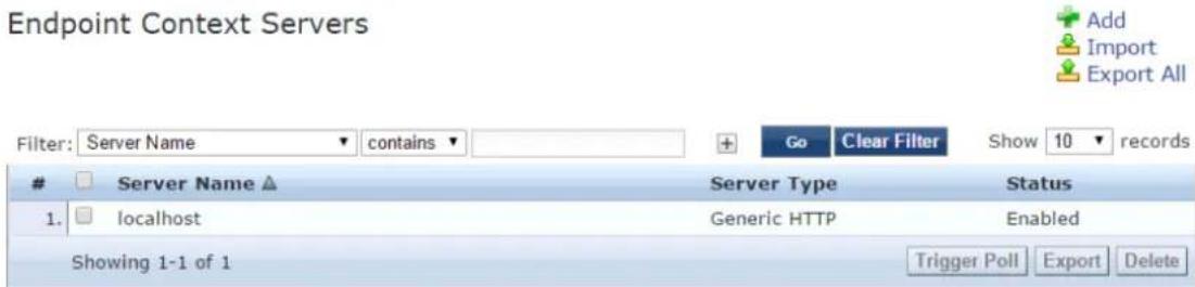
2. Click Add.
The Add Endpoint Context Server dialog opens. This dialog opens in the Server page.
Figure 624: Adding an Infoblox Endpoint Context Server
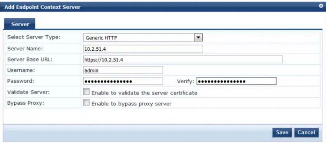
3. Enter the following information:
a. Select Server Type: From the drop-down list, select Generic HTTP.
b. Server Name: Enter the IP address of the Infoblox server.
c. Server Base URL: As you enter the IP address in the Server Name field, the Server Base URL is populated automatically with the same IP address.
d. Password: Enter the password for this server, then verify the password.
4. When finished defining the parameters in the Server page, click Save.
You return to the Endpoint Context Servers page, where the endpoint context server you added is now listed.
Adding a Context Server Action to the Infoblox Server
This section describes how to define an Infoblox Login action and specify the URL to post content from 1 W-ClearPass Policy Manager server to the Infoblox server.
To add a context server action to the Infoblox server:
1. Navigate to Administration > Dictionaries > Context Server Actions.
The Endpoint Context Server Actions page appears.
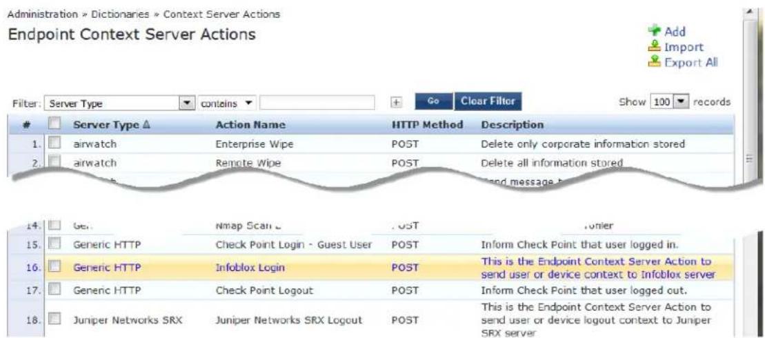
- Select the Infoblox Login endpoint context server action.
The Endpoint Context Server Details dialog for the selected action is displayed.
For descriptions of the parameters in the Endpoint Context Servers Details tabs, refer to Configuring
Endpoint Context Server Actions on page 614.
Figure 625: Selecting the Infoblox Server for the Endpoint Context Server Action
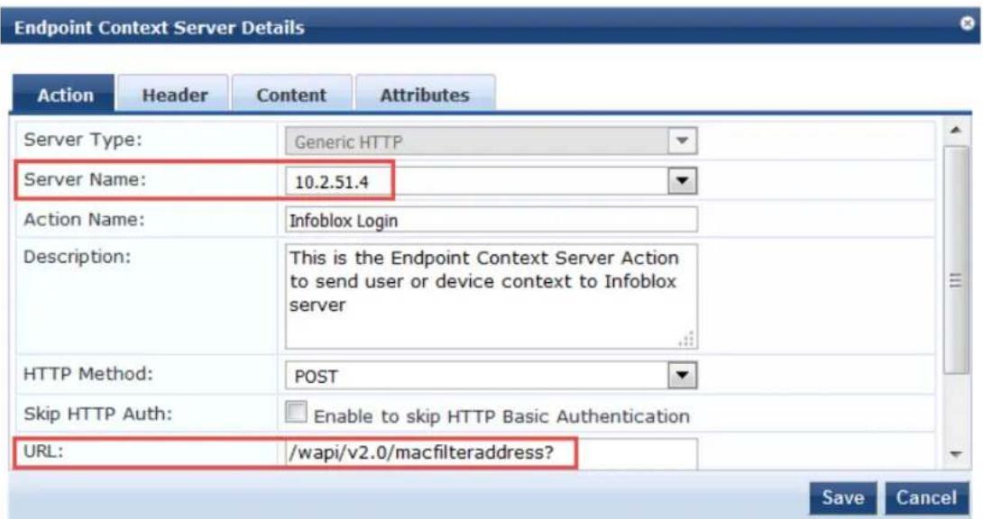
- Server Name: Select the IP address of the Infoblox server.
- URL: Note the URL for posting content from the W-ClearPass server to the Infoblox server: /wapi/v2.0/macfilteraddress?
- Click Save.
Attributes Sent to the Infoblox Server
- To view the attributes that will be sent to the Infoblox server, click the Content tab.
As shown in Figure 626, the following attributes are sent in JSON format to the Infoblox server:
■ Filter name "ClearPass"
■ Username and MAC addresses of the authenticated devices
Figure 626: Attributes Sent to Infoblox Server
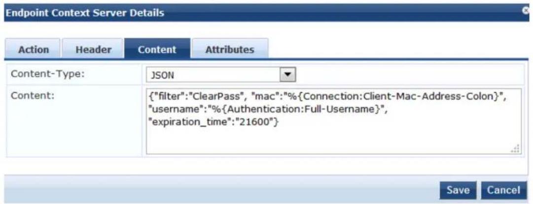
7. Click Cancel.
Creating an Infoblox Enforcement Profile
This section describes how to create a simple HTTP-based enforcement profile named "Infoblox Notify" that acts against the Infoblox Login action. For additional details on configuring enforcement profiles, see Configuring Enforcement Profile on page 373.
To create an Infoblox enforcement profile:
- Navigate to Configuration > Enforcement > Profiles.
The Enforcement Profiles page opens.
Figure 627: Enforcement Profiles Page
![Configuration > Enforcement > Profiles Enforcement Profiles Filter: Name ▼ contains ▼ 90 Clear Filter Show 10 records Name ▲ Type Description 1. □ [Aerohive - Terminate Session] RADIUS_CoA System-defined profile to disconnect user (Aerohive) 2. □ Agent-Healthy Agent 3. □ Agent-unhealthy Agent 4. □ [AirGroup Personal Device] RADIUS System-defined profile for an AirGroup personal device request 5. □ [AirGroup Response] RADIUS System-defined profile for any AirGroup request 6. □ [AirGroup Shared Device] RADIUS System-defined profile for an AirGroup shared device request 7. □ [Allow Access Profile] RADIUS System-defined profile to allow network access 8. □ [Allow Application Access Profile] Application System-defined profile to allow access to application 9. □ [Aruba TACACS read-only Access] TACACS System-defined profile for read-only access to Aruba device 10. □ [Aruba TACACS root Access] TACACS System-defined profile for root access to Aruba device Showing 1-10 of 171 ▶ Copy Export Delete](/content/2026/05/842116/images/0bf7a98dda2940c54da018f753280f0dcc8b6491a05522bd2d90ec54d65454f9.jpg)
2. Click Add.
The Add Enforcement Profiles dialog appears.
Figure 628: Adding the Infoblox Enforcement Profile
Configuration » Enforcement » Profiles » Add Enforcement Profile
Enforcement Profiles
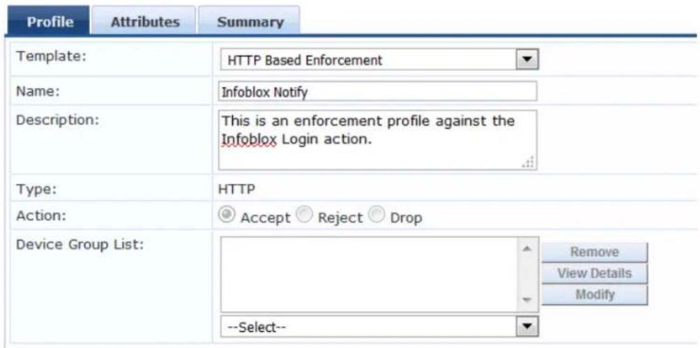
- Configure the Add Enforcement Profile page as follows:
a. Template: Select HTTP Based Enforcement.
For details on configuring HTTP-based enforcement profiles, see HTTP Based Enforcement Profile on page 406.
b. Name: Enter Infoblox Notify.
c. Description: Optionally, enter a description of this enforcement profile.
d. Click Next.
The Enforcement Profiles Attributes page appears.
Figure 629: Specifying the Target Server and Enforcement Action
Configuration » Enforcement » Profiles » Add Enforcement Profile
Enforcement Profiles

- Configure the Enforcement Profile Attributes page as follows:
a. Target Server: Select the IP address of the Infoblox server.
b. Action: Select Infoblox Login.
c. Click Save.
You return to the Enforcement Profiles page, where the Infoblox Notify enforcement profile is now listed.
Configuring an Infoblox RADIUS Enforcement Profile

This section describes how to define a RADIUS Enforcement type profile for Infoblox. This profile configu parameters to define tunnel parameters, VLAN ID, and the termination action.
This configuration is specific to the lab environments in which this feature has been tested. The RADIUS: IETF attributes can take any values, depending on the lab environment.
For details on configuring a RADIUS-based enforcement policy, see RADIUS Based Enforcement Profile on page 407.
To define a RADIUS Enforcement profile:
- Navigate to Configuration > Enforcement > Profiles.
The Enforcement Profiles page appears.
- Click Add.
The Add Enforcement Profiles dialog appears.
Figure 630: Adding a RADIUS-Based Enforcement Profile
Configuration » Enforcement » Profiles » Add Enforcement Profile
Enforcement Profiles
| Profile | Attributes | Summary |
| Template: | RADIUS Based Enforcement | |
| Name: | Infoblox RADIUS Enforcement | |
| Description: | RADIUS-based enforcement that defines tunnel parameters, VLAN ID, and termination action. | |
| Type: | RADIUS | |
| Action: | Accept Reject Drop | |
| Device Group List: | ||
| --Select-- | ||
- Enter the following information:
a. Template: Select RADIUS Based Enforcement.
b. Name: Enter Infoblox RADIUS Enforcement.
c. Description: Optionally, enter a description of this profile.
d. Click Next.
The Enforcement Profiles Attributes page opens. In the following steps, you will add the four RADIUS Enforcement attributes illustrated in Figure 631.
Figure 631: Adding Attributes to the RADIUS Enforcement Profile
Configuration » Enforcement » Profiles » Add Enforcement Profile
Enforcement Profiles
| Profile | Attributes | Summary | |
| Type | Name Value | ||
| 1. | Radius:IETF | Tunnel-Private-Group-Id = data | |
| 2. | Radius:IETF | Session-Timeout = 21600 | |
| 3. | Radius:IETF | Tunnel-Type = VLAN (13) | |
| 4. | Radius:IETF | Termination-Action = RADIUS-Request (1) | |
| 5. | Click to add... | ||
Tunnel-Private\_Group-Id
- Click Click to add....
a. Type: Select Radius: IETF.
b. Name: Select Tunnel-Private_Group-Id.
c. Value: Enter the value configured for the Tunnel-Private_Group-Id attribute on the controller.
Session-Timeout
- Click Click to add....
a. Type: Select Radius: IETF.
b. Name: Select Session-Timeout.
c. Value: Enter 21600 (which equals six hours in seconds).
Tunnel-Type
- Click Click to add....
a. Type: Select Radius: IETF.
b. Name: Select Tunnel-Type.
c. Value: Select VLAN.
Termination-Action
- Click Click to add....
a. Type: Select Radius: IETF.
b. Name: Select Termination-Action.
c. Value: Select RADIUS-Request.
- Click Save.
You return to the Enforcement Profiles page. The following message is displayed: Enforcement profile "Infoblox RADIUS Enforcement" added
Creating an Infoblox Enforcement Policy
This section describes how to create an enforcement policy to act against the "Infoblox Notify" and "Infoblox RADIUS Enforcement" profiles so that external devices can authenticate against this policy.
For details on configuring enforcement policies, see Configuring Enforcement Policies on page 371.
To create an Infoblox Enforcement Policy:
- Navigate to Configuration > Enforcement > Policies.
The Enforcement Policies page opens.
- Click Add.
The Add Enforcement Policies page appears.
Figure 632: Adding the Infoblox Enforcement Policy
Enforcement Policies
![Enforcement Rules Summary Name: Infoblox Policy Description: Enforcement policy to act against the "Infoblox Notify" and "Infoblox RADIUS Enforcement" profiles Enforcement Type: RADIUS TACACS+ WEBAUTH (SNMP/Agent/CLI/CoA) Application Event Default Profile: [Allow Access Profile] View Details Modify](/content/2026/05/842116/images/65ea5bd2a58b296724e745ea5f303aa95ce14df3cecc7f3aea1fb98c6081d7d8.jpg)
- Enter the following information:
a. Name: Enter Infoblox Policy.
b. Description: Optionally, enter a description of this profile.
c. Enforcement Type: Set by default to RADIUS.
d. Default Profile: Select Allow Access Profile.
e. Click Next.
The Rules page appears.
- Click Add Rule.
The Rules Editor dialog appears.
Figure 633: Configuring Infoblox Enforcement Policy Rules
![Rules Editor Conditions Match ALL of the following conditions: Type Name Operator Value 1. Tips Role EQUALS [User Authenticated] 2. Click to add... Enforcement Profiles Profile Names: [RADIUS] Infoblox RADIUS Enforcement [HTTP] Infoblox Notify Move Up Move Down Remove --Select to Add-- Save Cancel](/content/2026/05/842116/images/3ea436a97412e79e2b0d6c6547815f9989feefa7afdfa9b15dd858184534d39a.jpg)
- In the Conditions panel, click Click to add, then enter the following information:
a. Type: Select Tips.
b. Name: Select Role.
c. Operator: Select EQUALS.
d. Value: Select User Authenticated.
- In the Enforcement Profiles panel:
a. Click Select to Add.
You must add the enforcement profiles in the order specified here.
b. Select [RADIUS] Infoblox RADIUS Enforcement.
c. Click Select to Add.
d. Select [HTTP] Infoblox Notify.
-
Click Save.
-
To view the Infoblox enforcement policy summary, click the Summary tab.
Figure 634: Summary of the Infoblox Enforcement Policy
Enforcement Policies
![Enforcement Rules Summary Enforcement: Name: Infoblox Policy Description: Enforcement policy to act against the "Infoblox Notify" and "Infoblox RADIUS Enforcement" profiles Enforcement Type: RADIUS Default Profile: [Allow Access Profile] Rules: Rules Evaluation Algorithm: First applicable Conditions Actions 1. [Tips:Role EQUALS [User Authenticated)] [RADIUS] Infoblox RADIUS Enforcement, [HTTP] Infoblox Notify](/content/2026/05/842116/images/b2d6ec1c6b7a687e25a0d4125e620e4a08777b06852279ce3cadb658b2ea0074.jpg)
- Check the summary information to make sure the policy is correct, make any changes if necessary, then click Save.
You return to the Enforcement Policies page where the new Infoblox Policy is now listed.
Defining an Infoblox Service
This section describes how to create a Generic RADIUS Enforcement wireless service named "Infoblox Ser for the policy "Infoblox Policy."
To create the wireless service:
-
Navigate to Configuration > Services.
The Services page opens. -
Click Add.
The Add Services page opens.
Figure 635: Adding an Infoblox Wireless Service
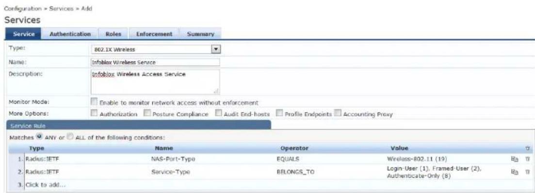
- Enter the following information:
a. Type: Select 802.1X Wireless.
b. Name: Enter Infoblox Wireless Service.
c. Description: Optionally, enter a description of this service.
d. In the Service Rule panel, set Matches to ANY, then click Next.
The Authentication page appears.
Figure 636: Specifying Wireless Service Authentication Settings
Configuration » Services » Add
Services
![Service Authentication Roles Enforcement Summary Authentication Methods: [EAP MSCHAPv2] [EAP PEAP] [EAP FAST] [EAP TLS] [EAP TTLS] Move Up Move Down Remove View Details Modify --Select to Add-- Authentication Sources: [Insight Repository] [Local SQL DB] Move Up Move Down Remove View Details Modify --Select to Add-- Strip Username Rules: Enable to specify a comma-separated list of rules to strip username prefixes or suffixes](/content/2026/05/842116/images/79e32fa7537870edf4292158ec3225e50ba38b0ece21a2133b8ec172c398d744.jpg)
- Enter the following information:
a. Authentication Methods: Select the authentication method.
This example uses EAP MSCHAPv2.
b. Authentication Sources: Select the authentication source(s).
This example uses Local SQL DB.
- Select the Enforcement tab.
Figure 637: Specifying the Enforcement Policy for the Service
![Configuration > Services > Add Services Service Authentication Roles Enforcement Summary Use Cached Results: Use cached Roles and Posture attributes from previous sessions Enforcement Policy: Infoblox Policy Modify Add new Enforcement Policy Enforcement Policy Details Description: Default Profile: [Allow Access Profile] Rules Evaluation Algorithm: first-applicable Conditions Enforcement Profiles 1. [Tips:Role EQUITS [User Authenticated)] Infoblox RADIUS Enforcement, Infoblox Notify](/content/2026/05/842116/images/2b0b98549f45d460bff0148ff7235f3129657115a8cb2df8c5dcd6ccf6a8059c.jpg)
- From the Enforcement Policy drop down, select Infoblox Policy, then click Next.
The Infoblox Wireless Service Summary page is displayed.
- Check the summary information to make sure the service is correct, make any changes if necessary, to click Save.
You return to the Services page where the new Infoblox Wireless Service is now listed.
Authenticating External Devices Against the Infoblox Service
This section defines the configuration on the Infoblox server to receive the MAC address and username context from W-ClearPass.
The following procedure adds an IPv4 network that is used as a DHCP pool to assign IP addresses to the external devices that must be authenticated.
To configure an Infoblox server to authenticate external devices:
- Log into the Infoblox server.
The Infoblox IPAM Tasks page opens.
Figure 638: Infoblox Server Initial Page
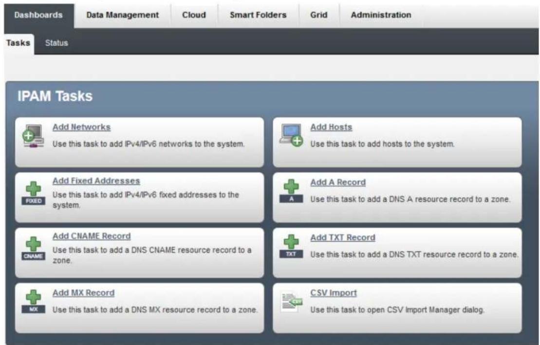
- Select the Data Management tab, then select the DHCP tab.
The DHCP Networks page appears.
Figure 639: Adding an IPv4 Network
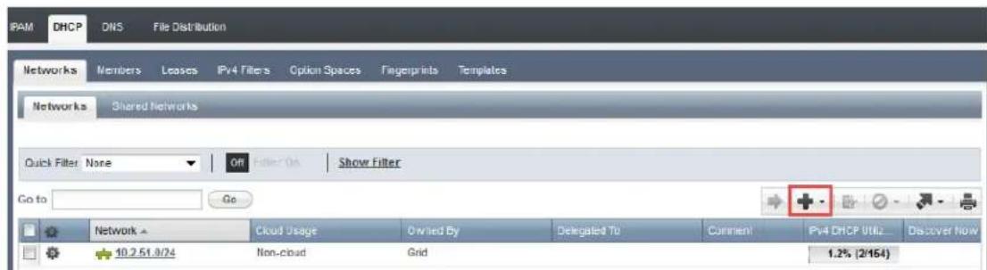
- To add a new network, click the Plus icon.
The Add IPv4 Network Wizard begins.
Figure 640: Adding an IPv4 Network
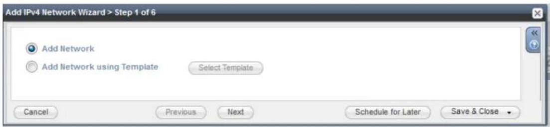
- With Add Network selected by default, click Next.
The following screen appears.
Figure 641: Specifying the Netmask
- In the Netmask field, specify the netmask for the new network.
The netmask is set by default to /24 (that is, a Class C IP address), but you can set the netmask to any appropriate netmask value for your network.
-
To add an IPv4 network, in the Networks panel, click the Plus sign (see Figure 641).
-
In the Networks field, enter the IP address of the network, then click Next.
The Members screen appears.
Figure 642: Adding Members
- Click the Plus sign.
While adding members for the DHCP pool, the members group from Data Management > DHCP > Members is populated automatically.
- Click Next.
The following screen appears.
Figure 643: Specifying the Lease Time (Session-Timeout Value)
-
In the Lease Time Override panel, click Override.
-
In the Lease Time field, enter 21600; from the drop-down, select Seconds. Then click Next.
The Lease Time value you enter here must correspond to the Session-Timeout value defined under Infoblox RADIUS Enforcement (see Figure 631).
The Extension Attributes screen opens. No changes are required here.
12.Click Next.
The Create IPv4 Network screen opens. You can choose to create the network now or schedule it for a later day and time.

Figure 644: Scheduling Date and Time for Creating the IPv4 Network
- Specify when you choose to create the IPv4 network, then click Save & Close.
The new network is created.
Figure 645: New IPv4 Network Created
Creating a Filter to Accept Information from the W-ClearPass Server
To create a filter to accept information from the W-ClearPass server:
- From the Data Management > DHCP tab, select the newly created network. The Networks page opens.
- Select the IPv4 Filters tab.
- To add a filter, click the Plus sign.
The Add IPv4 MAC Address Filter dialog opens.
- In the Name field, enter W-ClearPass.

The name of the filter must correspond to the filter value in the Endpoint Context Server Content page (see Attributes Sent to the Infoblox Server on page 632).
- Optionally, enter a comment to describe this filter, then click Next.
Step 2 of the Add IPv4 MAC Address Filter wizard appears. - In the Lease Time fields, enter 21600 Seconds, then click Next.
Figure 646: Specifying Lease Time in the IPv4 MAC Address Filter
The Lease Time value entered here must correspond to the Session-Timeout value defined under Infoblox RADIUS Enforcement Profile (see Session-Timeout on page 636).
Step 3 of the IPv4 MAC Address Filter wizard appears.
Figure 647: Specifying the MAC Address Expiration in the IPv4 MAC Address Filter
- For the Default MAC Address Expiration setting:
a. Select the Automatically Expires in button.
b. Specify 21600 Seconds.
c. Then click Next.
The Extensible attributes screen appears.
8 No changes are required for this step, so click Next.
In Step 5, the Schedule Change dialog appears.

Figure 648:
- Specify the Schedule Change settings:
a. If you wish to run the MAC address filter now, select Now.
b. If you wish to schedule the MAC address filter for later, select Later and specify the Start Date and Start Time.
c. When finished with the Schedule Change settings, click Save & Close.
Integrating W-ClearPass with Juniper Networks SRX
This section provides the following information:
- Adding a Juniper Networks SRX Endpoint Context Server
- Adding a Context Server Action to the Juniper SRX Server
• Viewing or Modifying Juniper Networks SRX Endpoint Context Server Actions - Creating a Juniper SRX Enforcement Profile
- Creating a Juniper SRX Enforcement Policy
• Defining a Juniper SRX Wireless Service
For more information about the parameters that you must enter to configure this endpoint context serve consult Juniper Network's documentation.
Integrating W-ClearPass with Juniper Networks SRX typically tags the username context, as well as the ex devices being authenticated, along with its respective MAC address, which further simplifies IP address management on the Juniper SRX server side.
This section describes the configurations that you must make on the W-ClearPass server in order for the W-ClearPass server to send data to a Juniper Networks SRX server.
Adding a Juniper Networks SRX Endpoint Context Server
To add a Juniper Networks SRX Endpoint Context Server:
-
Navigate to Administration > External Servers > Endpoint Context Servers.
The Endpoint Context Servers page appears. -
Click Add.
The Add Endpoint Context Server dialog appears. This dialog opens in the Server page.
- From the Select Server Type drop-down, select Juniper Networks SRX.
Server Page
The following dialog is displayed (see Figure 649).
Figure 649: Adding a Juniper Networks SRX Endpoint Context Server > Server Dialog
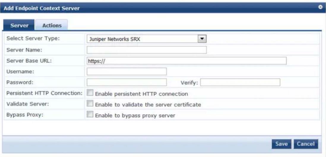

You can add multiple endpoint context servers of the same type.
- Enter the appropriate values for each of the Juniper Networks SRX Add Endpoint Context Server parar described in Table 346.
- When satisfied with the settings, click Save.
Table 346: Specifying Juniper Networks SRX Endpoint Context Server - Server Page Parameters
| Parameter Action/Description | |
| Select Server Type Choose | Juniper Networks SRX. |
| Server Name Enter a valid server name. You can enter an IP address or a host name. | |
| Server Base URL Enter the full URL for the server. You can append a custom port, such as for an MDM server: https://yourserver.yourcompany.com:customerportnumber | |
| Username Enter the user name. | |
| Password | Enter and verify the password. |
| Verify Password | |
| Validate Server | Enable the Validate Server check box to validate the server certificate. Enabling this option activates the Certificate tab. |
| Enable Server | Enable this option to fetch endpoints from the server. Enabling this option activates the Poll Status tab. |
| Bypass Proxy Enable this option to bypass the proxy server. | |
Adding a Context Server Action to the Juniper SRX Server
Figure 650 displays the Juniper Network SRX Add Endpoint Context Server > Actions page:
Figure 650: Adding a Juniper Networks SRX Endpoint Context Server > Actions Page
Administration » External Servers » Endpoint Context Servers
Endpoint Context Servers

Add
Import
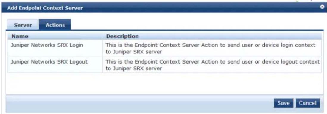
Table 347 describes the Endpoint Context Server Actions that are available:
Table 347: Juniper Networks SRX Endpoint Context Server Actions
| Action Description | |
| Juniper Networks SRX Login Endpoint | Context Server action to send a user or device login context to a Juniper SRX server. |
| Juniper Networks SRX Logout Endpoint | Context Server action to send a user or device logout context to a Juniper SRX server. |
Viewing or Modifying Juniper Networks SRX Endpoint Context Server Actions
To view or modify the Juniper Networks SRX endpoint context server actions:
- Navigate to Administration > Dictionaries > Context Server Actions.
The Endpoint Context Server Actions page appears.
- Select the Juniper Networks SRX endpoint context server action of interest.
The Endpoint Context Server Details dialog for the selected action is displayed.
Figure 651: Endpoint Context Server Details for the Juniper SRX Action
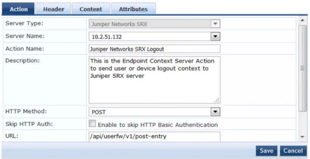
For descriptions of the parameters in the Endpoint Context Servers Details pages, refer to Configuring Endpoint Context Server Actions on page 614.
- If necessary, modify the parameters in the Action page, then click Save.
- To specify a content type and add non-default context server attributes, select the Content tab.
Figure 652 shows the content of the Juniper Networks SRX Login action:
Figure 652: Content for the Juniper Networks SRX Login Action
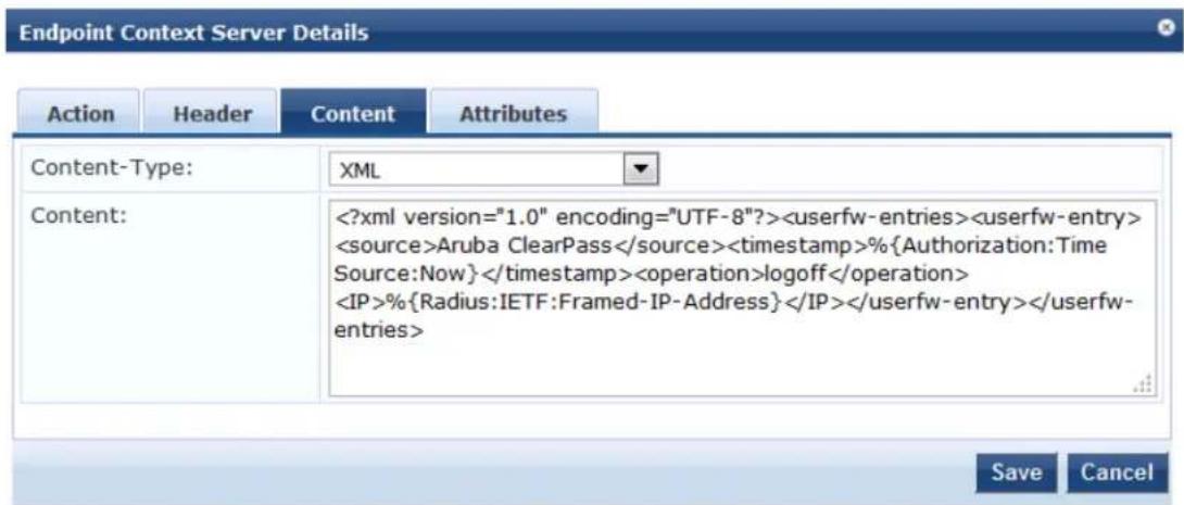
Figure 653 shows the content of the Juniper Networks SRX Logout action:
Figure 653: Content for the Juniper Networks SRX Logout Action
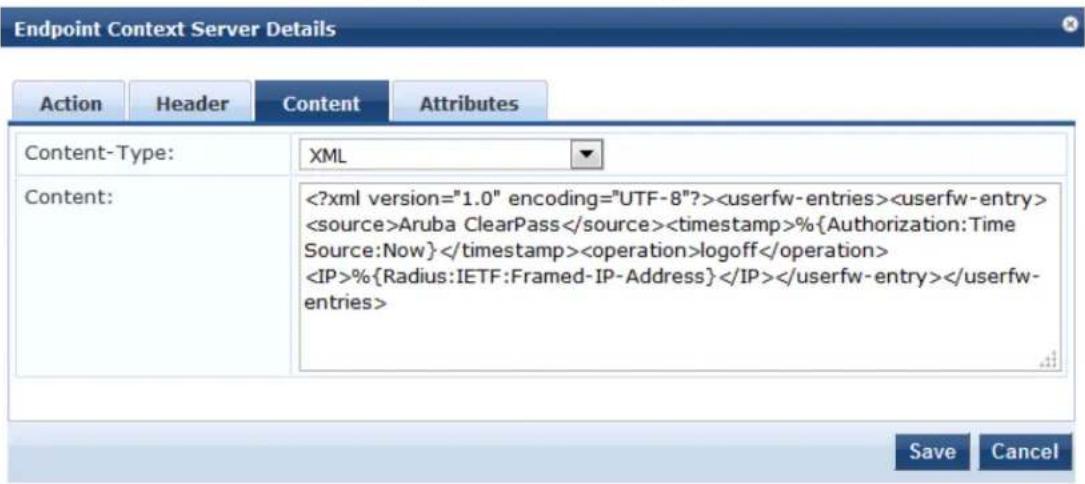
- Make any necessary changes to the Content page, then click Save.
You return to the Endpoint Context Servers page, where the endpoint context server you added is now listed.
Creating a Juniper SRX Enforcement Profile
This section describes how to create a session-notification enforcement profile named "Juniper SRX Notify" that acts against the Juniper SRX Login action.
For details on configuring enforcement profiles, see Configuring Enforcement Profile on page 373.
To create a Juniper SRX enforcement profile:
- Navigate to Configuration > Enforcement > Profiles.
The Enforcement Profiles page appears.
Figure 654: Enforcement Profiles Page
![Configuration > Enforcement > Profiles Enforcement Profiles Filter: Name contains Go Clear Filter Show 10 records Name ▲ Type Description 1. [Aerohive - Terminate Session] RADIUS_CoA System-defined profile to disconnect user (Aerohive) 2. Agent-Healthy Agent 3. Agent- unhealthy Agent 4. [AirGroup Personal Device] RADIUS System-defined profile for an AirGroup personal device request 5. [AirGroup Response] RADIUS System-defined profile for any AirGroup request 6. [AirGroup Shared Device] RADIUS System-defined profile for an AirGroup shared device request 7. [Allow Access Profile] RADIUS System-defined profile to allow network access 8. [Allow Application Access Profile] Application System-defined profile to allow access to application 9. [Aruba TACACS read-only Access] TACACS System-defined profile for read-only access to Aruba device 10. [Aruba TACACS root Access] TACACS System-defined profile for root access to Aruba device Showing 1-10 of 171 ▶ Copy Export Delete](/content/2026/05/842116/images/5c23ab82b7d097d1227277c57436f4f7429876e88ef0e9f1acf6ccc568ee95c7.jpg)
- Click Add.
The Add Enforcement Profiles dialog appears.
Figure 655: Adding the Juniper SRX Enforcement Profile
Configuration » Enforcement » Profiles » Add Enforcement Profile
Enforcement Profiles
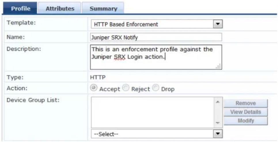
- Configure the Add Enforcement Profile page as follows:
a. Template: Select Session Notification Enforcement.
For details on configuring session notification enforcement profiles, see Session Notification Enforcement Profile on page 411
b. Name: Enter Juniper SRX Notify.
c. Description: Optionally, enter a description of this enforcement profile.
d. Click Next.
The Enforcement Profiles Attributes page appears. In the following steps, you will add the four Session Notify Enforcement attributes illustrated in Figure 656.
Figure 656: Adding Attributes to the Enforcement Profile
Configuration » Enforcement » Profiles » Add Enforcement Profile
Enforcement Profiles
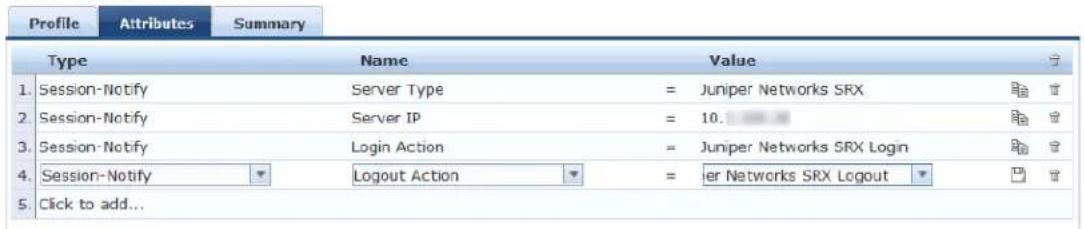
Server Type
- Click Click to add....
a. Type: Select Session-Notify.
b. Name: Select Server Type.
c. Value: Select Juniper Networks SRX.
Server IP
- Click Click to add....
a. Type: Select Session-Notify.
b. Name: Select Server IP.
c. Value: Select the IP address of the Juniper SRX server.
Login Action
- Click Click to add....
a. Type: Select Session-Notify.
b. Name: Select Login Action.
c. Value: Select Juniper Networks SRX Login.
Logout Action
- Click Click to add...
a. Type: Select Session-Notify.
b. Name: Select Logout Action.
c. Value: Select Juniper Networks SRX Logout.
- Click Save.
You return to the Enforcement Profiles page, where the Juniper Networks SRX Notify enforcement profile is now listed.
Creating a Juniper SRX Enforcement Policy
This section describes how to create an enforcement policy to act against the "Juniper SRX Notify" profile so that external devices can authenticate against this policy.
For details on configuring enforcement policies, see Configuring Enforcement Policies on page 371.
To create a Juniper SRX Enforcement Policy:
- Navigate to Configuration > Enforcement > Policies.
The Enforcement Policies page appears.
- Click Add.
The Add Enforcement Policies dialog appears.
Figure 657: Adding the Juniper SRX Enforcement Policy
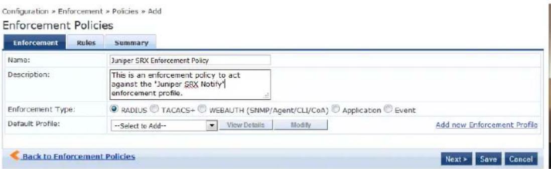
- Enter the following information:
a. Name: Enter Juniper SRX Enforcement Policy.
b. Description: Optionally, enter a description of this profile.
c. Enforcement Type: Set by default to RADIUS.
d. Default Profile: Select Allow Access Profile.
e. Click Next.
The Rules page opens.
- Click Add Rule.
The Rules Editor dialog opens.
Figure 658: Configuring Juniper SRX Enforcement Policy Rules
![Rules Editor Conditions Match ALL of the following conditions: Type Name Operator Value 1: Tips Role EQUALS [User Authenticated] 2: Click to add... Enforcement Profiles Profile Names: [Post Authentication] Juniper SRX Notify Move Up Move Down Remove --Select to Add-- Save Cancel](/content/2026/05/842116/images/85e60d95191f866c8f40a5563ff866e8b1bb9a5541ae834351c41605b4d26b14.jpg)
Specify Conditions
- In the Conditions panel, click Click to add, then enter the following information:
a. Type: Select Tips.
b. Name: Select Role.
c. Operator: Select EQUALS.
d. Value: Select User Authenticated.
Specify the Enforcement Profile
- In the Enforcement Profiles panel:
a. Click Select to Add.
b. Select [Post Authentication] Juniper SRX Notify.
-
Click Save.
-
To view the Juniper SRX enforcement policy summary, click the Summary tab.
Figure 659: Summary of the Juniper SRX Enforcement Policy
Configuration » Enforcement » Policies » Edit - Juniper SRX Enforcement Policy
Enforcement Policies - Juniper SRX Enforcement Policy
![Summary Enforcement Rules Enforcement: Name: Juniper SRX Enforcement Policy Description: Enforcement policy to act against the "Juniper SRX Notify" profile Enforcement Type: RADIUS Default Profile: [Allow Access Profile] Rules: Rules Evaluation Algorithm: First applicable Conditions Actions 1. (Tips:Role EQUALS [User Authenticated]) Juniper SRX Notify](/content/2026/05/842116/images/8716b4c745fcb5bb7eb1beebb76123c610d2a62a01e6bf3acdaafc53a81716c9.jpg)
- Check the summary information to make sure the enforcement policy is correct, make any changes if necessary, then click Save.
You return to the Enforcement Policies page where the new Juniper SRX Policy is now listed.
Defining a Juniper SRX Wireless Service
This section describes how to create a n 802.1X wireless service named "Juniper SRX Wireless Service" to applied to the policy "Juniper SRX Policy."
To create the Juniper SRX wireless service:
- Navigate to Configuration > Services.
The Services page appears.
- Click Add.
The Add Services page appears.
Figure 660: Adding a Juniper SRX Wireless Service
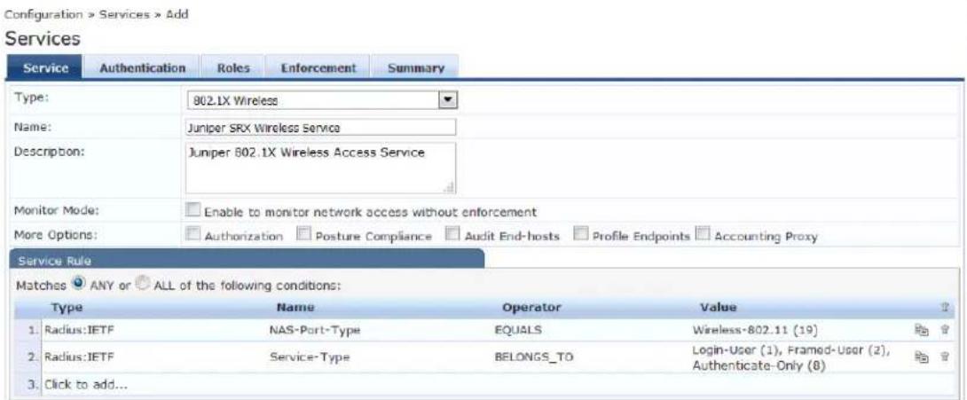
- Specify the following information:
a. Type: Select 802.1X Wireless.
b. Name: Enter Juniper SRX Wireless Service.
c. Description: Optionally, enter a description of this service.
d. In the Service Rule panel, set Matches to ANY, then click Next.
The Authentication page appears.
Figure 661: Specifying the Wireless Service Authentication Settings
Configuration » Services » Add
Services
![Service Authentication Roles Enforcement Summary Authentication Methods: [EAP MSCHAPv2] [EAP PEAP] [EAP FAST] [EAP TLS] [EAP TTLS] Move Up Move Down Remove View Details Modify --Select to Add-- Authentication Sources: [Insight Repository] [Local SQL DB] Move Up Move Down Remove View Details Modify --Select to Add-- Strip Username Rules: Enable to specify a comma-separated list of rules to strip username prefixes or suffixes](/content/2026/05/842116/images/3846eb720aa16a7b2750d0b3ac63f41855092faad3bd17fa0c74225ce1820257.jpg)
- Specify the following information:
a. Authentication Methods: Select the authentication method.
This example uses EAP MSCHAPv2 as the authentication method.
b. Authentication Sources: Select the authentication source(s).
This example uses [Local User Repository] [Local SQL DB]. as the authentication source.
- Select the Enforcement tab.
Figure 662: Specifying the Enforcement Policy for the Juniper SRX Wireless Service
![Configuration > Services > Add Services Service Authentication Roles Enforcement Summary Use Cached Results: Use cached Roles and Posture attributes from previous sessions Enforcement Policy: Juniper SRX Enforcement Policy Modify Add new Enforcement Policy Enforcement Policy Details Description: Enforcement policy to act against the "Juniper SRX Notify" profile Default Profile: [Allow Access Profile] Rules Evaluation Algorithm: first-applicable Conditions Enforcement Profiles 1. [Tips Role EQUALS [User Authenticated]] Juniper SRX Notify](/content/2026/05/842116/images/0dbdcd99f06df44d434236bb32091f1b7c10cac811bf808d14107d299da2cef9.jpg)
- From the Enforcement Policy drop-down, select Juniper SRX Policy, then click Next.
The Juniper SRX Wireless Service Summary is displayed.
- Check the service summary information to make sure the service is correct, make any changes if need then click Save.
You return to the Services page where the new Juniper SRX Wireless Service is now listed.
Adding a JAMF Endpoint Context Server
Consult the endpoint manufacturer's documentation for information about the parameters that you must enter to configure this endpoint. The following figure displays the Add Endpoint Context Server - Server (JAMF) tab:
Figure 663: Add Endpoint Context Server - Server (JAMF) Tab
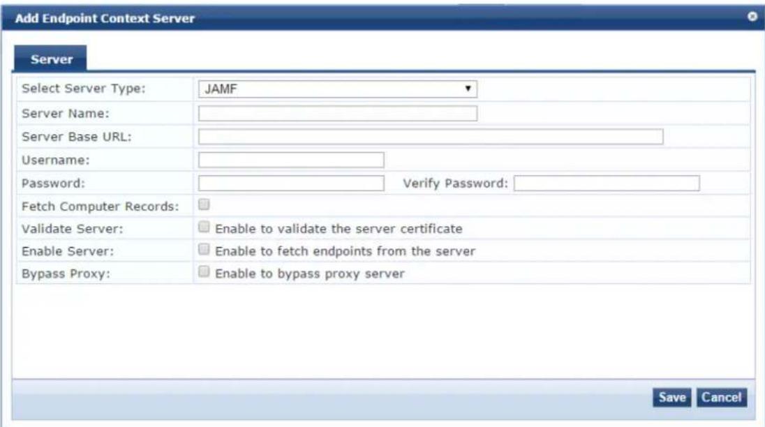

You can add more than one endpoint context server of the same type. For example, you can add more than one AirWatch endpoint context server.
The following table describes the Add Endpoint Context Server - Server (JAMF) tab parameters:
Table 348: Add Endpoint Context Server - Server (JAMF) Tab Parameters
| Parameter Description | |
| Select Server Type | Choose JAMF from the drop-down list. |
| Server Name Enter | a valid server name. You can enter an IP address or hostname. |
| Server Base URL | Enter the full URL for the server. You can append a custom port, such as for an MDM https://yourserver.yourcompany.com:customerportnumber. |
| Username Enter the username. | |
| Password Enter and verify the password. | |
| Verify Password | |
| Fetch Computer Records | Enable to fetch computer records. |
| Validate Server | Enable to validate the server certificate. Checking this option enables the Certificate tab. |
| Enable Server | Enable to fetch endpoints from the server. |
| Bypass Proxy | Enable to bypass proxy server. |
Adding a MaaS360 Endpoint Context Server
Consult the endpoint manufacturer's documentation for information about the parameters that you must enter to configure this endpoint.
Server Tab
The following figure displays the Add Endpoint Context Server - Server (MaaS360) tab:
Figure 664: Add Endpoint Context Server - Server (MaaS360) Tab
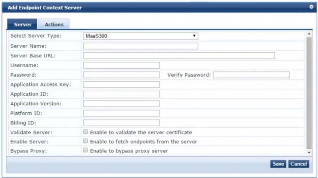

You can add more than one endpoint context server of the same type. For example, you can add more than one AirWatch endpoint context server.
The following table describes the Add Endpoint Context Server - Server (MaaS360) tab parameters:
Table 349: Add Endpoint Context Server - Server (MaaS360) Tab Parameters
| Parameter Description | |
| Select Server Type | Choose MaaS360 from the drop-down list. |
| Server Name | Enter a valid server name. You can enter an IP address or hostname. |
| Server Base URL | Enter the full URL for the server. You can append a custom port, such as for an MDM se https://yourserver.yourcompany.com:customerportnumber. |
| Username Enter the username. | |
| Password Enter and verify the password. | |
| Verify Password | |
| Application Access Key | Enter the application access key (API key). |
| Application ID | Enter the application ID. |
| Application Version | Enter the application version number. |
| Platform ID Enter the platform version number. | |
| Billing ID Enter the billing ID. | |
| Validate Server | Enable to validate the server certificate. Checking this option enables the Certificate tab. |
| Enable Server | Enable to fetch endpoints from the server. |
| Bypass Proxy | Enable to bypass proxy server. |
Actions Tab
The following figure displays the Add Endpoint Context Server - Actions (MaaS360) tab:
Figure 665: Add Endpoint Context Server - Actions (MaaS360) Tab
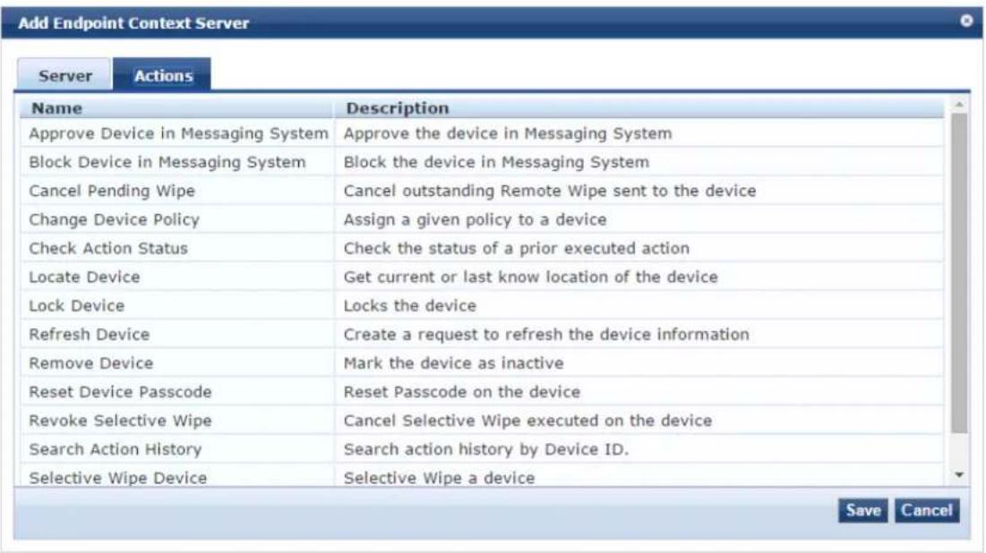
The following table describes the Add Endpoint Context Server - Actions (MaaS360) tab parameters:
Table 350: Add Endpoint Context Server - Actions (MaaS360) Tab Parameters
| Parameter Description | |
| Approve Device in Messaging System | Approve the device in Messaging System. |
| Block Device in Messaging System | Block the device in Messaging System. |
| Cancel Pending Wipe Cancel outstanding | Remote Wipe sent to the device. |
| Change Device Policy Assign a given policy to a device. | |
| Check Action Status | Check the status of a prior executed action. |
| Locate Device | Get current or last know location of the device. |
| Lock Device | Lock the device. |
| Refresh Device | Create a request to refresh the device information. |
| Remove Device | Mark the device as inactive. |
| Reset Device Passcode | Reset the pass code on the device. |
| Revoke Selective Wipe Cancel Selective Wipe executed on the device. | |
| Search Action History Search action history by Device ID. | |
| Selective Wipe Device Execute a Selective Wipe on a device. | |
| Wipe Device Delete all information stored on a device. | |
Adding a MobileIron Endpoint Context Server
Consult MobileIron's documentation for more information about the parameters that you must enter to configure this endpoint context server.
To add a MobileIron Endpoint Context Server:
- Navigate to Administration > External Servers > Endpoint Context Servers.
The Endpoint Context Servers page appears.
- Click Add.
The Add Endpoint Context Server dialog appears. This dialog opens in the Server tab.
- From the Select Server Type drop-down, select MobileIron.
Server Page
The following figure displays the Add Endpoint Context Server - Server (MobileIron) dialog:
Figure 666: Adding a MobileIron Endpoint Context Server - Server Page
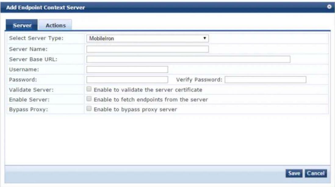

You can add multiple endpoint context servers of the same type.
- Enter the appropriate values for each of the MobileIron Add Endpoint Context Server parameters desc in Table 351.
- When satisfied with the settings, click Save.
Table 351: Adding a MobileIron Endpoint Context Server - Server Page Parameters
| Parameter Description | |
| Select Server Type 1. Choose MobileIron from the drop-down list. | |
| Server Name 2. Enter a | valid server name. You can enter an IP address or host name. |
| Server Base URL 3. Enter | the full URL for the server. You can append a custom port, such as for an MDM server: https://yourserver.yourcompany.com:customerportnumber |
| Username | 4. Enter the username. |
| Password | 5. Enter and verify the password. |
| Verify Password | |
| Validate Server | 6. Enable to validate the server certificate.Checking this option enables the Certificate tab. |
| Enable Server | 7. Enable to fetch endpoints from the server. |
| Bypass Proxy 8. Enable to bypass the proxy server. | |
Actions Page
The following figure displays the Add Endpoint Context Server - Actions (MobileIron) page:
Figure 667: Adding a MobileIron Endpoint Context Server - Actions Page
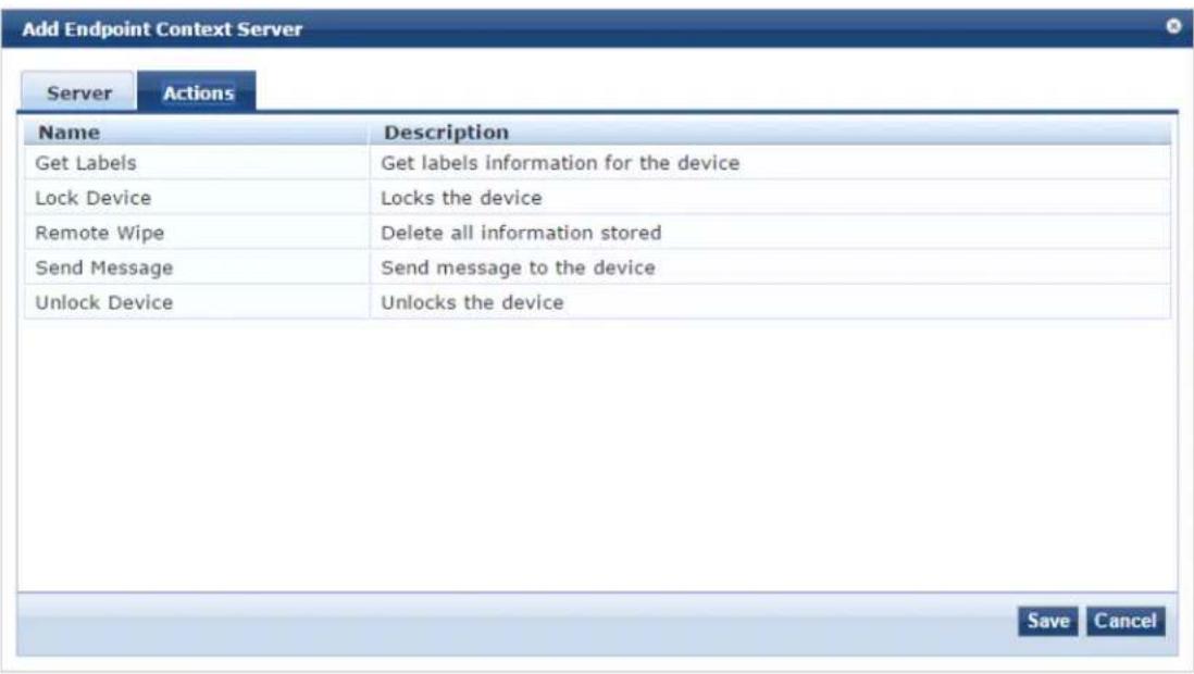
Table 352 describes the Endpoint Context Server Actions that are available:
Table 352: Adding a MobileIron Endpoint Context Server - Actions Page Parameters
| Parameter Description | |
| Get Labels Get label information of the device. | |
| Lock Device Lock the device. | |
| Remote Wipe Delete all information stored on the device. | |
| Send Message Send message to the device. | |
| Unlock Device Unlock the device. | |
9. When satisfied with the Action settings, click Save.
Adding a Palo Alto Networks Firewall Endpoint Context Server
Consult Palo Alto Networks' documentation for more information about the parameters that you must er to configure this endpoint context server.
To add a Palo Alto Networks Firewall endpoint context server:
- Navigate to Administration > External Servers > Endpoint Context Servers.
The Endpoint Context Servers page opens.
- Click Add.
The Add Endpoint Context Server dialog opens.
- From the Select Server Type drop-down, select Palo Alto Networks Firewall.
The following dialog is displayed (see Figure 668).
Figure 668: Add Endpoint Context Server > Palo Alto Networks Firewall Dialog
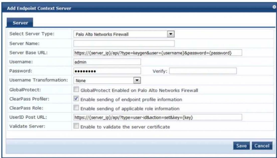
- Enter the appropriate values for each of the Palo Alto Networks Firewall > Add Endpoint Context Server parameters described in Table 353.
- When satisfied with the settings, click Save.
Table 353: Add Endpoint Context Server > Palo Alto Networks Firewall Parameters
| Parameter Action/Description | |
| Select Server Type | Choose Palo Alto Networks Firewall from the drop-down list. |
| Server Name Enter a valid | server name. You can enter an IP address or a hostname. |
| Server Base URL Enter the | server base URL in the following format:https://{server_ip}/api/?type=keygen&user={username}&password={password} |
| Username | Enter the username. |
| Password | Enter and verify the password. |
| Verify Password | |
| Username Transformation | Choose one of the following options:None: Do not use any username transformation.Prefix NetBIOS name: Use the Prefix NetBIOS name in UID updates.Use Full Username: Use the full username in UID updates. |
| GlobalProtect | Enable this option to send an HIP (Host Information Profiles) report to the firewall.You must enable the GlobalProtect license on the firewall for this to work. |
| ClearPass Profiler | Select this check box to enable sending of endpoint profile information. |
| ClearPass Role | Select this check box to enable sending of the applicable role information. |
| UserID Post URL | Enter the user ID post URL in the following format:https://{server_ip}/api/?type=user-id&action=set&key={key}&cmd={cmd} |
| Validate Server | Enable to validate the server certificate. Checking this option enables the Certificate tab. |
Using the ClearPass Configuration API to Load Endpoint Context Servers
If you use the W-ClearPass Configuration API to load Palo Alto Networks endpoint context servers, you shall include the following attributes in the XML file:
• PA_Panorama_RegisterDevice
• PA_Panorama_SendRoles
Adding a Palo Alto Networks Panorama Endpoint Context Server
Consult Palo Alto Networks' documentation for more information about the parameters that you must er to configure this endpoint context server.
To add a Palo Alto Networks Panorama endpoint context server:
-
Navigate to Administration > External Servers > Endpoint Context Servers. The Endpoint Context Servers page opens.
-
Click Add. The Add Endpoint Context Server dialog opens.
-
From the Select Server Type drop-down, select Palo Alto Networks Panorama. The following dialog is displayed:
Figure 669: Add Endpoint Context Server > Palo Alto Networks Panorama Dialog
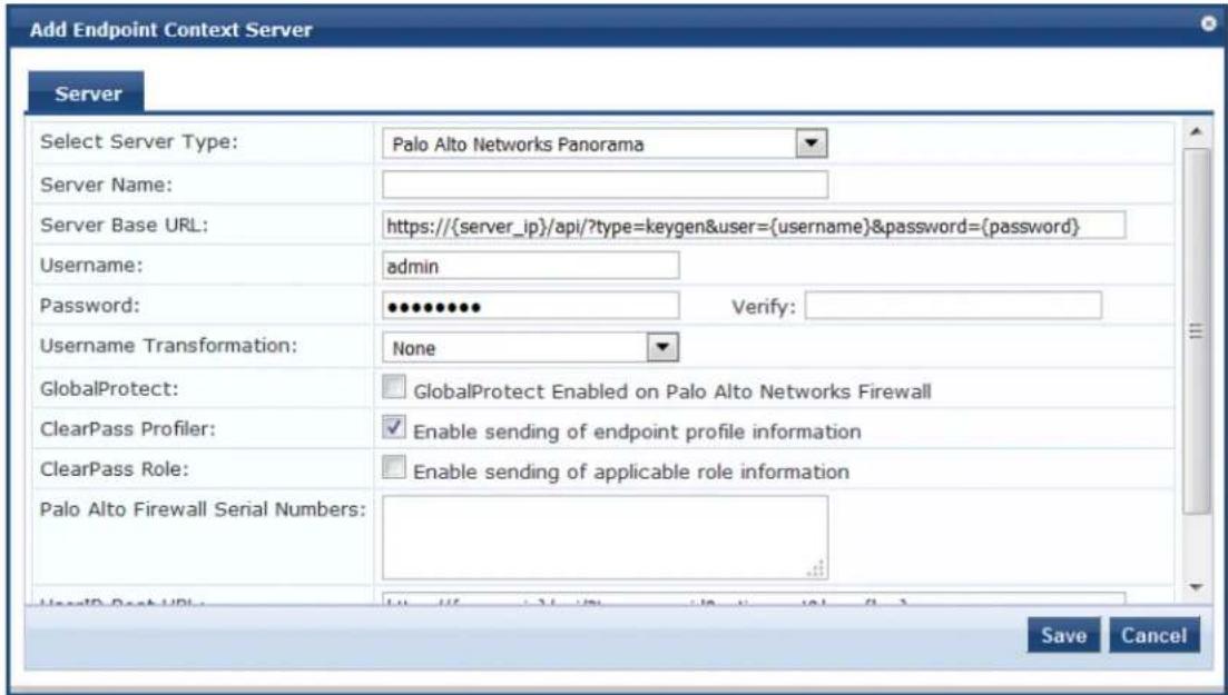

You can add more than one endpoint context server of the same type. For example, you can add more than one P Alto Networks endpoint context server.
- Enter the appropriate values for each of the Palo Alto Networks Panorama > Add Endpoint Context Server parameters described in Table 354.
- When satisfied with the settings, click Save.
Table 354: Add Endpoint Context Server > Palo Alto Networks Panorama Parameters
| Parameter Description | |
| Select Server Type Choose Palo Alto Networks Panorama from the drop-down list. | |
| Server Name Enter a valid server name. You can enter an IP address or hostname. | |
| Server Base URL Enter the server base URL in the following format: https://{server_ip}/api/?type=keygen&user={username}&password={password} | |
| Username Enter the username. | |
| Password Enter and verify the password. | |
| Verify Password | |
| Username Transformation Choose | one of the following options:None: Do not use any username transformation.Prefix NETBIOS name: Prefix NetBIOS name in UID updates.Use Full Username: Use full username in UID updates. |
| GlobalProtect Enable to send HIP | report to firewall. GlobalProtect license should be enabled on firewall for this to work. |
| ClearPass Profiler | Select this check box to enable sending of endpoint profile information. This parameter is enabled by default. |
| ClearPass Role | Select this check box to enable sending of the applicable role information |
| Palo Alto Firewall Serial Numbers | Enter the Palo Alto firewall serial numbers. |
| UserID Post URL | Enter the user ID post URL in the following format:https://{server_ip}/api/?type=user-id&action=set&key={key}&cmd={cmd} |
| Validate Server | Enable to validate the server certificate. Checking this option enables the Certificate tab. |
Using the ClearPass Configuration API to Load Endpoint Context Servers
If you use the W-ClearPass Configuration API to load Palo Alto Networks endpoint context servers, you should include the following attributes in the XML file:
• PA_Panorama_RegisterDevice
• PA_Panorama_SendRoles
Adding an SAP Afaria Endpoint Context Server
Consult the endpoint manufacturer's documentation for information about the parameters that you must enter to configure this endpoint.
Server Tab
The following figure displays the Add Endpoint Context Server - Server (SAP Afaria) tab:
Figure 670: Add Endpoint Context Server - Server (SAP Afaria) Tab
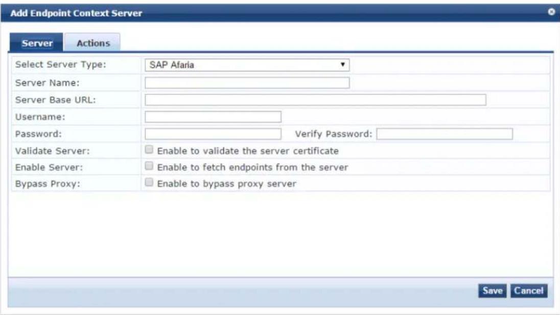

You can add more than one endpoint context server of the same type. For example, you can add more than one AirWatch endpoint context server.
The following table describes the Add Endpoint Context Server - Server (SAP Afaria) tab parameters:
Table 355: Add Endpoint Context Server - Server (SAP Afaria) Tab Parameters
| Parameter Description | |
| Select Server Type Choose SAP Afaria from the drop-down list. | |
| Server Name Enter a | valid server name. You can enter an IP address or a hostname. |
| Server Base URL Enter | the full URL for the server. You can append a custom port, such as for an MDM server: https://yourserver.yourcompany.com:customerportnumber. |
| Username Enter the username. | |
| Password Enter and verify the password. | |
| Verify Password | |
| Validate Server | Enable to validate the server certificate. Checking this option enables the Certificate tab. |
| Enable Server Enable to fetch endpoints from the server. | |
| Bypass Proxy Enable to bypass proxy server. | |
Actions Tab
The following figure displays the Add Endpoint Context Server - Actions (SAP Afaria) tab:
Figure 671: Add Endpoint Context Server - Actions (SAP Afaria) Tab
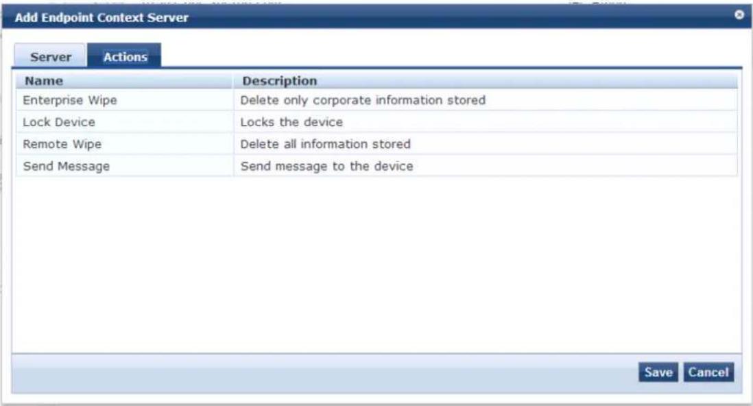
The following table describes the Add Endpoint Context Server - Actions (SAP Afaria) tab parameters:
Table 356: Add Endpoint Context Server - Actions (SAP Afaria) Tab Parameters
| Parameter Description | |
| Enterprise Wipe Delete corporate information related data. | |
| Lock Device Lock the associated device. | |
| Remote Wipe Delete all stored information. | |
| Send Message Send message to the device. |
Adding a SOTI Endpoint Context Server
Consult the endpoint manufacturer's documentation for information about the parameters that you must enter to configure this endpoint.
The following figure displays the SOTI Add Endpoint Context Server > Server dialog:
Figure 672: Adding a SOTI Endpoint Context Server > Server (SOTI) Dialog
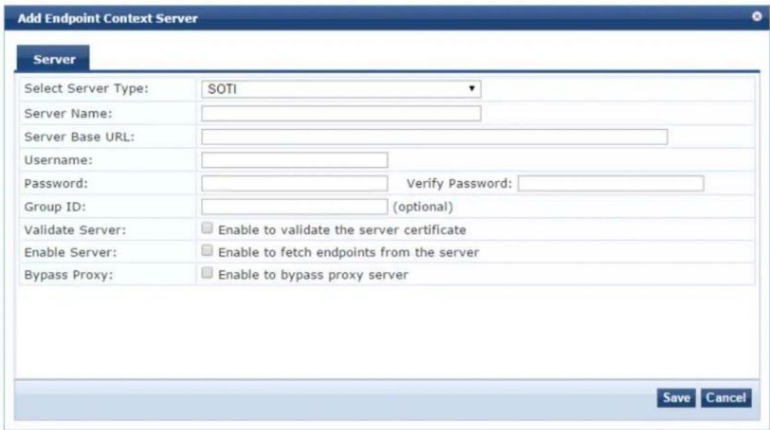

You can add more than one endpoint context server of the same type.
The following table describes the SOTI Add Endpoint Context Server > Server parameters:
Table 357: Adding a SOTI Endpoint Context Server > Server Parameters
| Parameter Action/Description | |
| Select Server Type | 1. Choose SOTI from the Select Server Type drop-down list. |
| Server Name 2. Enter | a valid server name. You can enter an IP address or a hostname. |
| Server Base URL 3. | Enter the complete URL for the SOTI server.You can append a custom port, such as for an MDM server:https://yourserver.yourcompany.com:customerportnumber |
| Username 4. Enter the | username for the SOTI server. |
| Password 5. Enter the | password, then verify it. |
| Verify Password | |
| Group ID 6. Enter the | group ID.This parameter is optional. |
| Validate Server | 7. Enable Validate Server to validate the server certificate.Enabling this option enables the Certificate tab. |
| Enable Server | 8. Enable Enable Server to fetch endpoints from the server. |
| Bypass Proxy 9. Enable | Bypass Proxy to bypass the proxy server. |
| 10. To save your changes, click Save. | |
Adding a XenMobile Endpoint Context Server
Consult the endpoint manufacturer's documentation for information about the parameters that you must enter to configure this endpoint. The following figure displays the Add Endpoint Context Server - Server (XenMobile) tab:
Figure 673: Add Endpoint Context Server - Server (XenMobile) Tab
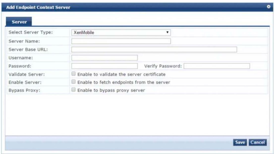
You can add more than one endpoint context server of the same type. For example, you can add more than one AirWatch endpoint context server.
The following table describes the Add Endpoint Context Server - Server (XenMobile) tab parameters:
Table 358: Add Endpoint Context Server - Server (XenMobile) Tab Parameters
| Parameter | Description |
| Select Server Type | Choose XenMobile from the drop-down list. |
| Server Name | Enter a valid server name. You can enter an IP address or hostname. |
| Server Base URL | Enter the server base URL in the following format: https://{server_ip} |
| Parameter Description | |
| /api/?type=keygen&user={username}&password={password} | |
| Username Enter the username. | |
| Password Enter and verify the password. | |
| Verify Password | |
| Validate Server | Enable to validate the server certificate. Checking this option enables the Certificate tab. |
| Enable Server Enable to | fetch endpoints from the server. |
| Bypass Proxy Enable to | bypass proxy server. |
File Backup Servers
W-ClearPass Policy Manager provides the ability to push scheduled data securely to an external server. Y push the data using the SFTP and SCP protocols. Navigate to the Administration > External Servers > File Backup Servers page and click the Add link at the top-right corner. The Add File Backup Server page opens.
The following figure displays the Add File Backup Server page:
Figure 674: File Backup Servers - Add File Backup Server Page
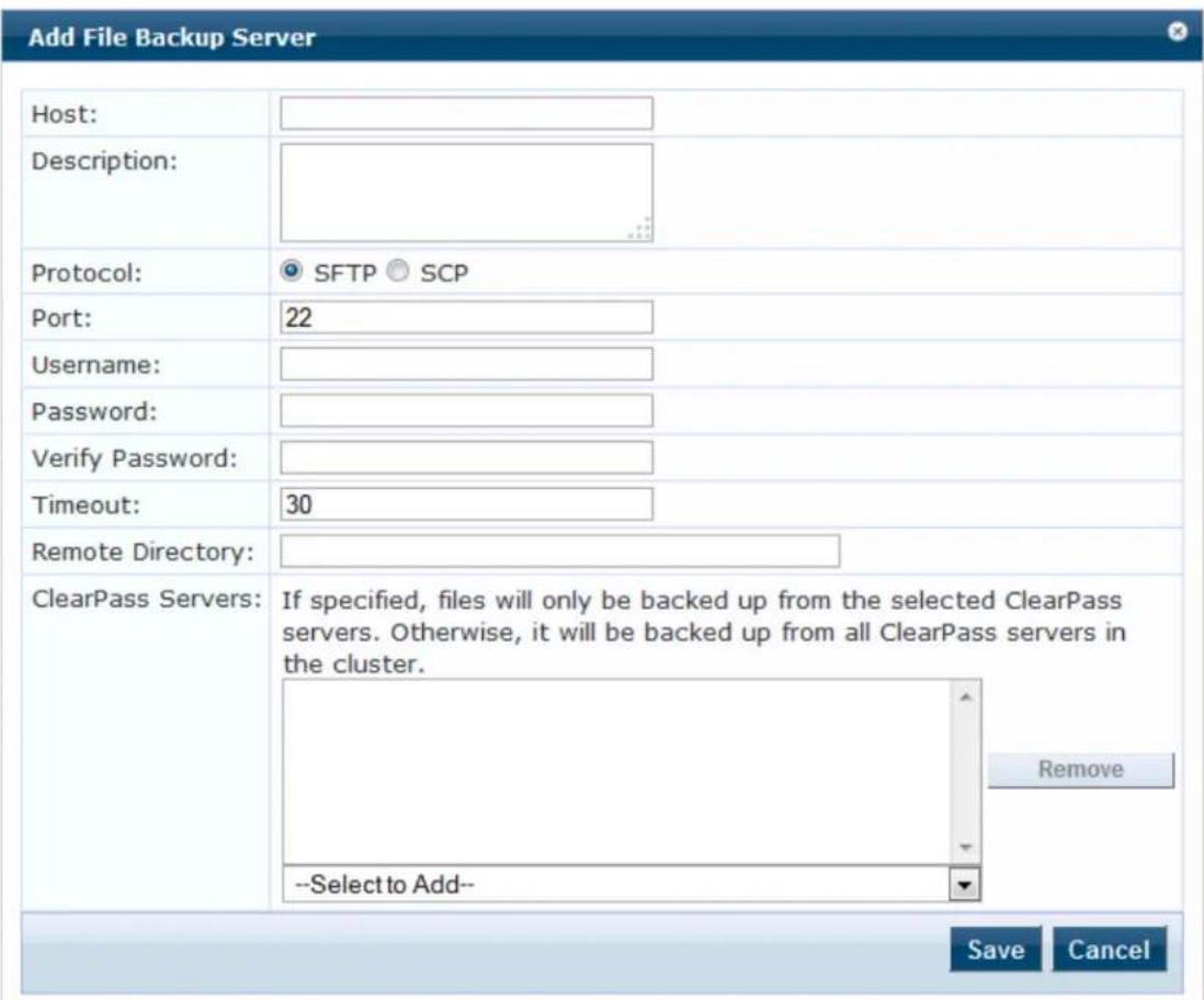
The following table describes the Add File Backup Server page parameters:
Table 359: Add File Backup Server Page Parameters
| Parameter Description | |
| Host Enter the name or IP address of the host. | |
| Description Enter the description that provides additional information about the File Backup server. | |
| Protocol Specify the protocol to be used to upload the generated reports to an external server. You can select from the following protocols:SFTP (SSH File Transfer Protocol)SCP (Session Control Protocol) | |
| Port Specify the port number. The default port is 22. | |
| Username | Enter the user name and password of the host server. |
| Password Enter | the user name of the host server. |
| Verify Password | Enter the password of the host server. |
| Timeout | Specify the timeout value in seconds. The default value is 30 seconds. |
| Remote Directory | Specify the location in this field to which the files to be copied. A folder will be automatically created in the file path that you specify based on the selected ClearPass servers in theClearPass Serversfield. |
| ClearPass Servers | Specify the W-ClearPass servers. If a servers are specified, files will only be backed up from the selected ClearPass servers. Otherwise, it will be backed up from all ClearPass servers in the cluster. You can select the servers from theSelect to Adddrop-down list. |
Server Certificates
This section describes the following topics:
• Server Certificate Page on page 671
• Server Certificate Type on page 672
- Creating and Installing a Self-Signed Certificate on page 676
- Importing a Server Certificate on page 679
- Exporting a Server Certificate on page 680
Server Certificate Page
The information provided on the Server Certificate page depends on whether the RADIUS Server Certificate type or the HTTPS Service Certificate type is assigned to the selected server.
To configure the server certificate:
- Navigate to Administration > Certificates > Server Certificate.
The following figure displays the Server Certificate page:
Figure 675: Server Certificate Page
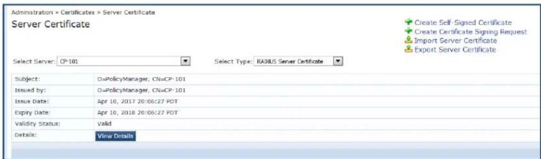
- Specify the Server Certificate parameters as described in the following table:
Table 360: Server Certificate Parameters
| Parameter Action/Description | |
| Create Self-Signed Certificate | Opens the Create Self-Signed Certificate page where you can create and install a Self-Signed Certificate. For more information, see Creating and Installing a Self-Signed Certificate on page 676. |
| Create Certificate Signing Request | Opens the Create Certificate Signing Request page where you can create and install a Certificate Signing Request. For more information, see Creating a Certificate Signing Request on page 674. |
| Import Server Certificate | Opens the Import Server Certificate page where you can import a certificate that has been exported previously. For more information, see Importing a Server Certificate on page 679. |
| Export Server Certificate | On clicking this link, the self-signed certificate is downloaded. For more information, see Exporting a Server Certificate on page 680. |
| Select Server | Select a server in the cluster for server certificate operations. |
| Select Type Select a certificate type. The options are:RADIUS Server CertificateHTTPS Server CertificateThe availability of two certificate types (internally signed and publicly signed) can provide deployment flexibility. | |
| View Details Click to view the certificate details. | |
Server Certificate Type
W-ClearPass Policy Manager provides two types of server certificates.
RADIUS Server Certificate
This page displays the parameters configured when a self-signed certificate with a RADIUS Server Certifica created and installed.
The following figure displays the RADIUS Server Certificate page:
Figure 676: RADIUS Server Certificate Page
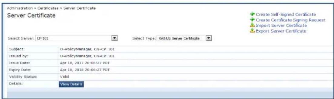
The following table describes the RADIUS Server Certificate parameters:
Table 361: RADIUS Server Certificate Parameters
| Parameter | Description |
| Subject Displays Organization and Common Name. | |
| Issued by Displays Organization and Common Name. | |
| Issue Date Displays the date the self-signed certificate is installed. | |
| Expiry Date Displays the date (in days) when the self-signed certificate expires. | |
| Validity Status | Displays the validity status of the self-signed certificate. |
| Details Click | the View Details button to view details about the certificate, such as Signature Algorithm, Subject Public Key Info, and more. |
HTTPS Server Certificate
The HTTPS Server Certificate page displays the parameters configured after a self-signed certificate with an HTTPS Server Certificate is created and installed.
The page contains data about the server certificate, Intermediate CA Certificate, and Root CA Certificate. To see details about Signature Algorithm, Public Key Info, and more, click the View Details button.
The following figure displays the HTTPS Server Certificate page:
Figure 677: HTTPS Server Certificate Page
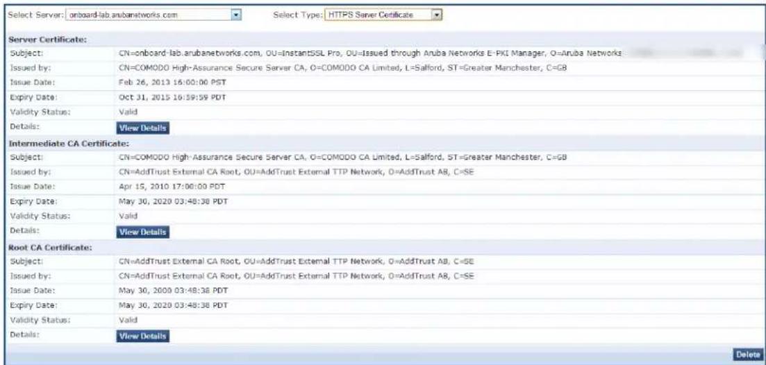
The following table describes the HTTPS Server Certificate parameters:
Table 362: HTTPS Server Certificate Parameters
| Parameter | Action/Description |
| Subject Displays Organization and Common Name. | |
| Issued by Displays Organization and Common Name that issued the server certificate. | |
| Issue Date Displays the date the self-signed certificate is installed. | |
| Expiry Date Displays the date when the self-signed certificate expires. | |
| Validity Status | Displays the validity status of the self-signed certificate. |
| Details To view details about the certificate, such as Signature Algorithm and Subject Public Key Info, click theView Detailsbutton. | |
Creating a Certificate Signing Request
After you select a server and a certificate type, you can create a certificate signing request. This task creates a self-signed certificate to be signed by a CA (Certificate Authority).
To create a certificate signing request:
- Navigate to Administration > Certificates > Server Certificate.
- Select a server.
- Click the Create Certificate Signing Request link.
The Create Certificate Signing Request dialog opens:
Figure 678: Create Certificate Signing Request Dialog
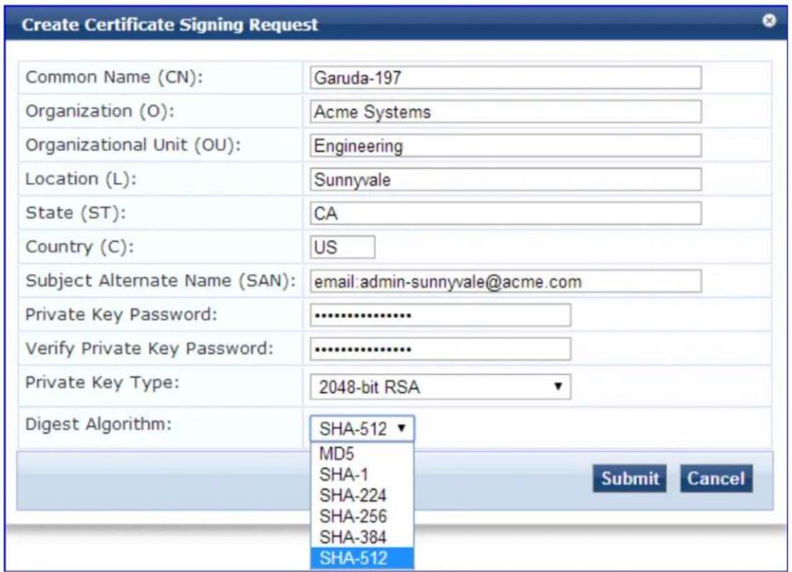
- Specify the Create Certificate Signing Request parameters as described in Table 363, then click Submit.
Table 363: Create Certificate Signing Request Parameters
| Parameter Action/Description | |
| Common Name (CN) Enter the name associated with this entity.This can be a host name, IP address, or other name. The default is the fully-qualified domain name (FQDN). This field is mandatory. | |
| Organization (O) Enter the name of the organization. This field is optional. | |
| Organizational Unit (OU) Enter the name of the department, division, section, or other meaningful name. This field is optional. | |
| Location (L)State (ST)Country (C) | Optionally, enter the name of the location, state, country. |
| Subject Alternate Name (SAN) | Optionally, enter the alternative names for the specified Common Name in one of the following formats:email: email_addressURI: uriIP: ip_addressdns: dns_name■ rid: id |
| Private Key Password Verify Private Key Password | Enter the private key password, then verify it. |
| Private Key Type Select the length for the generated private key types from the following options:■ 1024-bit RSA■ 2048-bit RSA. This is the default.■ 4096-bit RSA■ X9.62/SECG curve over a 256 bit prime field■ NIST/SECG curve over a 384 bit prime field | |
| Digest Algorithm Select the message digest algorithm from the following options:■ SHA-1■ SHA-224■ SHA-256■ SHA-384■ SHA-512. This is the default. | |
After you create a Certificate Signing Request form and click Submit, the generated certificate signing request is displayed.
- Copy the certificate and paste it into the Web form as part of the enrollment process.
- To save the Certificate Signing Request file and the private key password file, click Download CSR and Private Key Files.
Creating and Installing a Self-Signed Certificate
After you select a server and a certificate type, you can create and install a self-signed certificate.
When Common Criteria mode is enabled, the Create-Self Signed Certificate option for both HTTPS and RADIUS certificates is not available from the Administration > Certificates > Server Certificate page (for more information, see Mode Parameters on page 556).
Creating a Self-Signed Certificate
To create a self-signed certificate:
- Navigate to Administration > Certificates > Server Certificate.
- Select a server.
- Click the Create Self-Signed Certificate link.
The Create Self-Signed Certificate page opens.

Figure 679: Create Self-Signed Certificate Page
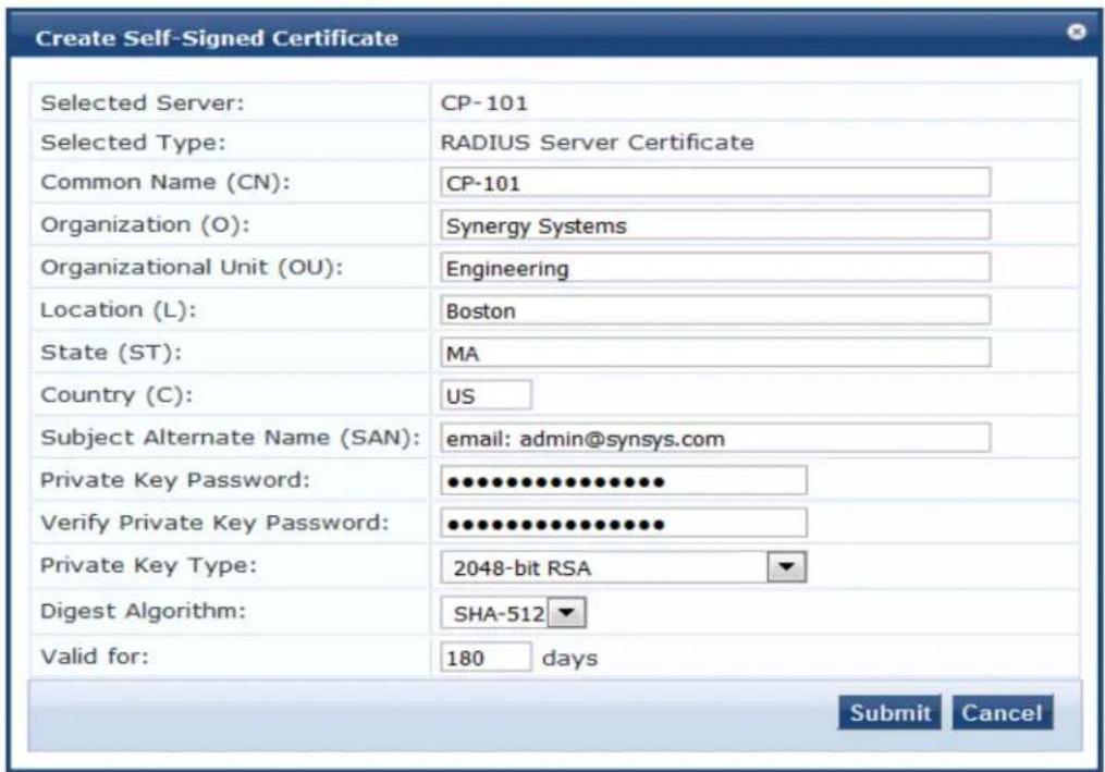
- Configure the Create Self-Signed Certificate parameters as described in Table 364.
Table 364: Create Self-Signed Certificate Parameters
| Parameter Action/Description | |
| Selected Server | Displays the name of the selected server on theServer Certificatepage. |
| Selected Type Displays | the selected certificate type for the server on theServer Certificatepage. |
| Common Name (CN) | Enter the name associated with this entity. This can be a host name, IP address, or other meaningful name. This field is mandatory. |
| Organization (O) Enter | the name of the organization. This field is optional. |
| Organizational Unit (OU) | Enter the name of the department, division, section, or other meaningfname. This field is optional. |
| Location (L) Enter the | name of the location, state, country, and/or other meaningfulname. These fields are optional. |
| State (ST) | |
| Country (C) | |
| Subject Alternate Name (SAN) | Enter the alternative name for the specified Common Name.NOTE: Enter the Subject Alternate Name in one of the following forma email: email_address■ URI:uri■ IP:ip_address■ dns:dns_name■ rid:idThis field is optional. |
| Private Key Password | Enter the Private Key password, then verify the password. |
| Verify Private Key Password | |
| Private Key Type Select | the length for the generated private key types from the following options:■ 1024-bit RSA■ 2048-bit RSA■ 4096-bit RSA■ X9.62/SECG curve over a 256 bit prime field■ NIST/SECG curve over a 384 bit prime fieldThe default private key type is2048-bit RSA. |
| Digest Algorithm Select | the message digest algorithm from the following options:■ MD5■ SHA-1■ SHA-224■ SHA-256■ SHA-384■ SHA-512NOTE:The MD5 algorithm is not available in FIPS mode. |
| Valid for Enter the certificate duration in number of days. The default is180days. | |
5. Click Submit.
The Create Self-Signed Certificate dialog opens (as shown in Figure 680 below).
Installing a Self-Signed Certificate
This page displays a summary of the values specified in the Create Self-Signed Certificate page and provides the Install button to install the self-signed certificate.
- Check the summary values for the Self-Signed Certificate.
Figure 680: Create Self-Signed Certificate Page
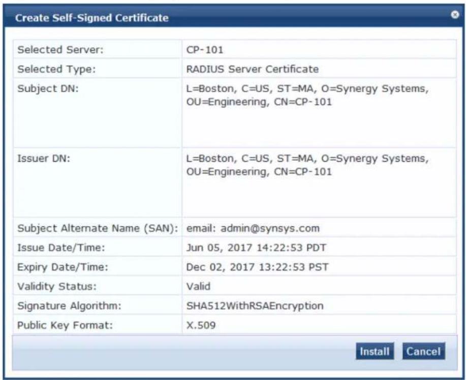
2. Click Install.
After you click Install, Policy Manager generates a message about the status of the certificate installation.
If the installation is successful the page displays the message:
Server Certificate updated successfully.
- Because all services are restarted after a successful certificate installation, you must click Logout, then log in to the W-ClearPass client to continue.
Importing a Server Certificate
W-ClearPass does not support importing the HTTPS Server Certificate chain or RADIUS Server Certificate code in P7b Base64 format. A P7B file contains only certificates and chain certificates (intermediate certificate authorities), not the private key.
To import a server certificate into the current W-ClearPass server:
-
Navigate to Administration > Certificates > Server Certificate.
-
Click the Import Server Certificate link.
The Import Server Certificate dialog opens:
Figure 681: Import Server Certificate Dialog
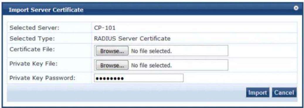
For security reasons, certificates signed using SHA1RSA are not recommended. Importing certificates signed with stronger keys, such as RSA with a length of more than 1024 bits, is recommended.
- Specify the Import Server Certificate parameters as described in the following table:
Table 365: Import Server Certificate Parameters
| Parameter Action/Description | |
| Selected Server Displays the name of the selected W-ClearPass server. | |
| Selected Type Displays the type of server certificate that was selected. | |
| Certificate File Browse to the certificate file to be imported. | |
| Private Key File Browse to the private key file to be imported. | |
| Private Key Password | Enter the private key password that was entered when the server certificate configured. |
- Click Import.
Exporting a Server Certificate
To export a server certificate from the current W-ClearPass server:
-
Navigate to Administration > Certificates > Server Certificate.
-
Click the Export Server Certificate link.
The Open ServerCertificate dialog opens.
- Open or save the file as necessary.
The default location for a server certificate to be exported is:
C:/
or
The zip file includes the server certificate (.crt file) and the private key (.pvk) file.

Certificate Trust List
The Certificate Trust List page displays a list of trusted Certificate Authorities (CA). On this page, you can view, or delete a certificate.
This section describes the following topics:
• Certificate Trust List Main Page on page 681
- Adding a Certificate on page 682
• Viewing a Certificate Detail on page 682
• Deleting a Certificate on page 682

You cannot import the certificates that are created with the MD5 digest algorithm to the Certificate Trust List in the FIPS mode.
Certificate Trust List Main Page
To display a list of trusted Certificate Authorities (CA), navigate to Administration > Certificates > Trust List.
The following figure displays the Certificate Trust List page:
Figure 682: Certificate Trust List Main Page
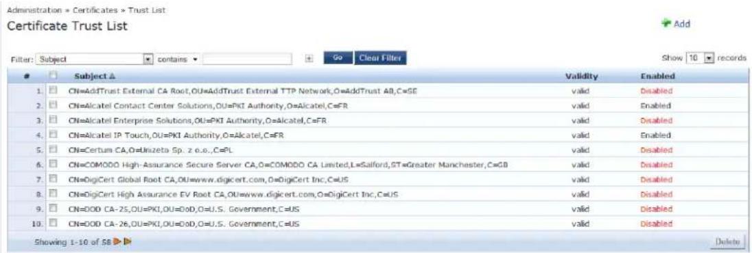
The Certificate Trust List (Administration > Certificates > Trust List) page can include the following certificates:
- DoD (Department of Defense) certificates - These are disabled by default. To enable this certificate, select a DoD certificate and click Enable in the View Certificate Details pop-up. A DoD certificate allows a browser to trust Web sites whose secure communications are authenticated by a DoD agency.
- Alcatel root certificate - These are disabled by default. To enable this certificate, select a DoD certificate and click Enable in the View Certificate Details pop-up. An Alcatel root certificate allows Alcatel Lucent IP phones to authenticate using EAP-TLS.
The following table describes the Certificate Trust List parameters:
Table 366: Certificate Trust List Parameters
| Parameter Description | |
| Subject Displays the Distinguished Name (DN) of the subject field in the certificate. | |
| Validity Indicates whether the CA certificate is valid or expired. | |
| Enabled Indicates whether the CA certificate is enabled or disabled. |
Adding a Certificate
- Navigate to Administration > Certificates > Trust List.
- Click the Add link on the top right section of the page.
- On the Add Certificate pop-up, click Choose File to browse the certificate file.
- Click Add Certificate.
The following figure displays the Add Certificate pop-up:
Figure 683: Add Certificate Pop-up
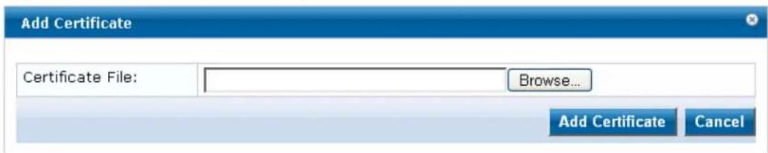
The following table describes the Add Certificate parameters:
Table 367: Add Certificate Parameters
| Parameter | Description |
| Certificate File | Click Choose File to browse the certificate file. |
Viewing a Certificate Detail
To view the details of a certificate, click any one of the entries from the certificate trust list. From the View Certificate Details pop-up, clicking the Enable button enables the CA certificate. When you enable a CA certificate, Policy Manager considers the entity whose certificate is signed by this CA to be trusted.
Deleting a Certificate
To delete a certificate:
- Navigate to Administration > Certificates > Trust List.
- Select the check box to the left of the certificate.
- Click Delete.
Certificate Revocation Lists
This section provides the following information:
- About Certificate Revocation Lists
- Updating All Certificate Revocation Lists
- Adding a Certificate Revocation List
• Deleting a Certificate Revocation List
About Certificate Revocation Lists
A certificate revocation list (CRL) is a list of digital certificates that have been revoked by the issuing Cer Authority (CA) before their scheduled expiration date and should no longer be trusted.
Certificate revocation lists are a type of blacklist and they are used by various endpoints, including Web browsers, to verify whether a certificate is valid and trustworthy.
Digital certificates are used in the encryption process to secure communications, most often by using the Transport Layer Security (TLS) or the Secure Sockets Layer (SSL) protocols. The certificate, which is signed the issuing certificate authority, also provides proof of the identity of the certificate owner.
Updating All Certificate Revocation Lists
When certificates are revoked by an external certificate authority, there is a need to be able to verify the Manager's authentication of that certificate fails, which requires an up-to-date certificate revocation list on W-ClearPass server if the Online Certificate Status Protocol (OCSP) is not in use.
You can poll all configured CRLs for an immediate update regardless of the schedule for each CRL.
To immediately update all certificate revocation lists:
- Navigate to Administration > Certificates > Revocation Lists.
The Certificate Revocation Lists page opens.
- Click the Check Now button.
All the updated CRLs are displayed immediately. The information in the Last Checked Time column is also updated for each newly-checked CRL.
Adding a Certificate Revocation List
To add a certificate revocation list:
- Navigate to Administration > Certificates > Revocation Lists.
The Certificate Revocation Lists page opens:
Figure 684: Certificate Revocation Lists Page
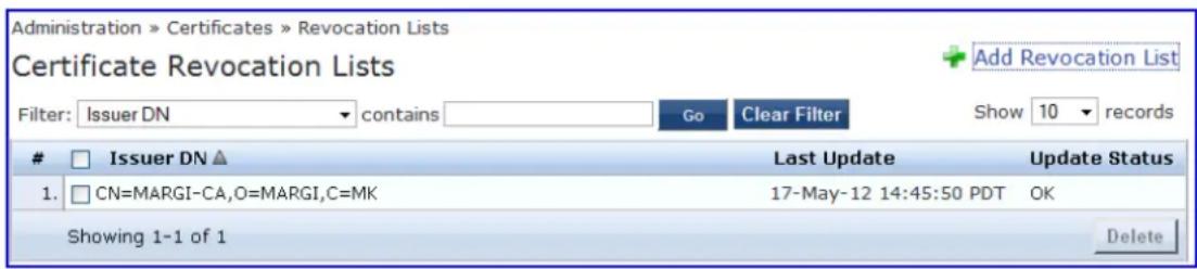
- Click the Add link on the top-right section of the page.
The Add Certificate Revocation List dialog opens:
Figure 685: Add Certificate Revocation List Dialog
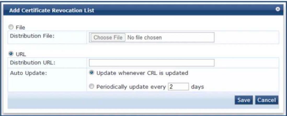
- Configure the Add Certificate Revocation List parameters as described in Table 368, then click Save.
Table 368: Add Certificate Revocation List Parameters
| Parameter Action/Description | |
| File Enable the File | button to use a distribution file as the Certificate Revocation List distribution point.File is enabled by default. |
| Distribution File | To select the distribution file to fetch the certificate revocation list, click Browse and select the CRL distribution file. |
| URL Enable the URL | button to use a URL as the CRL distribution point.Selecting URL enables the Distribution URL option. |
| Distribution URL | Specify the distribution URL to fetch the certificate revocation list. |
| Auto Update | To update the CRL at intervals specified in the list, select Update whenever CRL is updated.To check periodically and at the specified frequency (in hours), select Periodically update every ____ hour(s). |
| Bypass Proxy | To bypass the proxy server, click the Enable to bypass proxy server option. |
Deleting a Certificate Revocation List
To delete a certificate revocation list:
- Navigate to Administration > Certificates > Revocation Lists.
- Select the check box to the left of the certificate revocation list.
- Click Delete.
RADIUS Dictionary
This page includes the list of available vendor dictionaries. To configure RADIUS dictionaries, navigate to Administration > Dictionaries > RADIUS.
The following figure displays the RADIUS Dictionaries page:
Figure 686: RADIUS Dictionaries
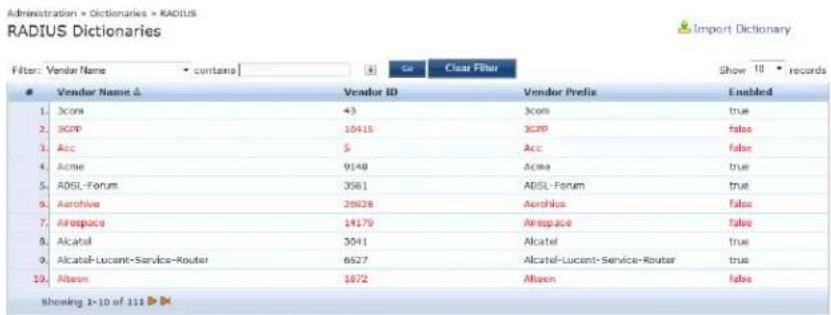
Click on a row view the dictionary attributes, to enable or disable the dictionary, and to export the dicti. For example, click on vendor IETF to see all IETF attributes and their data type. The following figure disp RADIUS IETF dictionary attributes pop-up:
Figure 687: RADIUS Attributes Pop-up
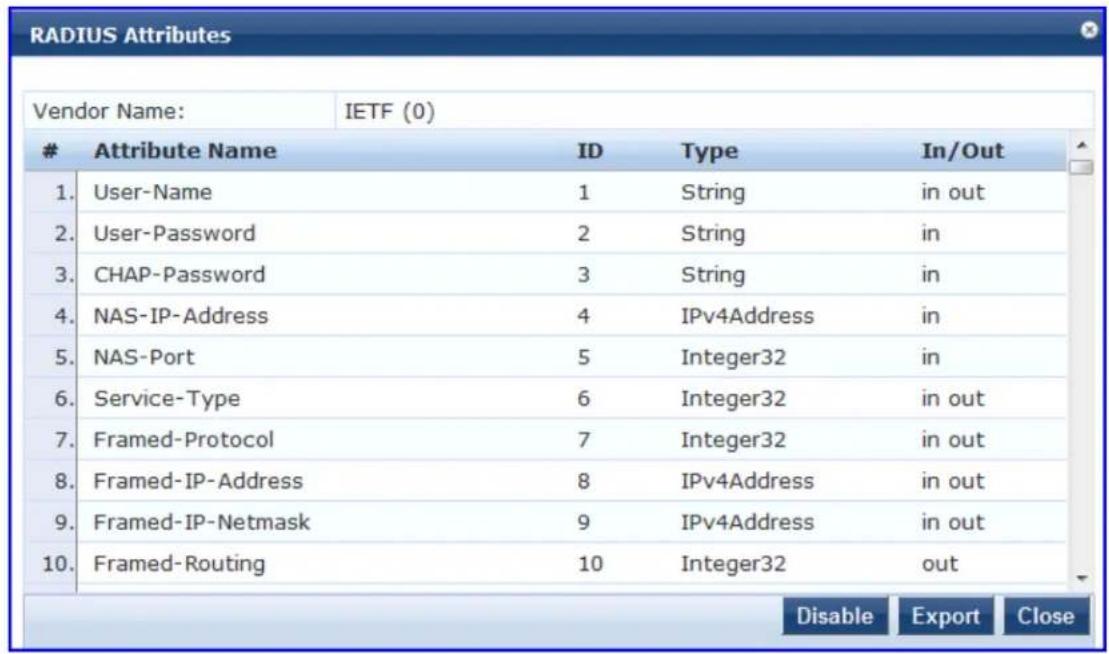
The following table describes the RADIUS Attributes parameters:
Table 369: RADIUS Dictionary Attributes Parameters
| Parameter Description | |
| Export Click to | save the dictionary file in XML format. You can make modifications to the dictionary and import the file back into Policy Manager. |
| Enable/Disable | Enable or disable this dictionary. Enabling a dictionary makes it appear in the Po Manager rules editors (Service rules, Role mapping rules, etc.). |
Import RADIUS Dictionary
You can add additional dictionaries using the Import too. To add a new vendor dictionary, navigate to Administration > Dictionaries > RADIUS, and click the Import link. To edit an existing dictionary, export an existing dictionary, edit the exported XML file, and then import the dictionary. To view the contents of the RADIUS dictionary, sorted by Vendor Name, Vendor ID, or Vendor Prefix, navigate to Administration > Dictionaries > RADIUS.
The following figure displays the Import from file pop-up:
Figure 688: Import RADIUS Dictionary Pop-up
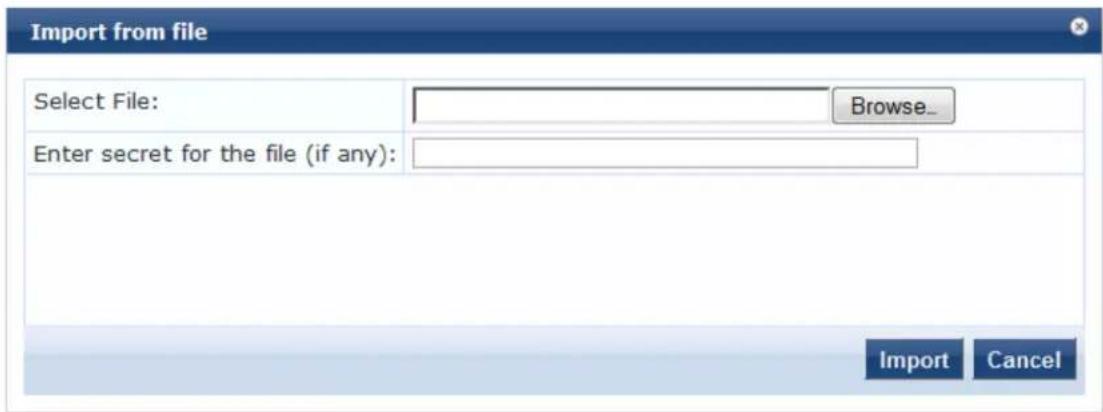
The following table describes the Import from file parameters:
Table 370: Import from file Parameters
| Parameter Description | |
| Select File | Browse to select the file that you want to import. |
| Enter secret for the file (if any) | If the file that you want to import is password protected, enter the secr |
TACACS+ Services Dictionary
To view the contents of the TACACS+ service dictionary, navigate to Administration > Dictionaries > TACACS+ Services and sort by Name or Display Name. To add a new TACACS+ service dictionary, click the
Import link. To add or modify attributes in an existing service dictionary, select the dictionary, export it, make edits to the XML file, and import it back into Policy Manager.
The following figure displays the TACACS+ Services Dictionaries page:
Figure 689: TACACS+ Services Dictionaries Page
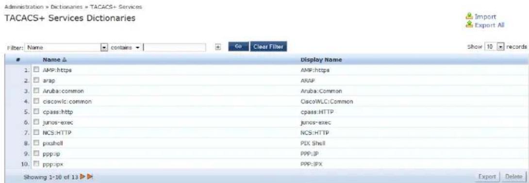
The following table describes the TACACS+ Services Dictionaries parameters:
Table 371: TACACS+ Services Dictionaries Parameters
| Parameter Description | |
| Import | Click to open theImport Dictionarypop up. Import the dictionary (XML file). |
| Export All Export all TACACS+ services into one XML file containing multiple dictionaries. | |
To export a specific service dictionary, select a service and click Export. To see all the attributes and their data types, click a service row. For example, click shell service to see all shell service attributes and their data
The following figure displays the TACACS+ Service Dictionary Attributes pop-up:
Figure 690: TACACS+ Service Dictionary Attributes Pop-up
| Display Name: | Shell | |||
| # | Name | Display Name | Type | Allowed Values |
| 1. | acl | Access control list | String | - |
| 2. | autocmd | Auto command | String | - |
| 3. | callback-line | Callback line | String | - |
| 4. | callback-rotary | Callback rotary | String | - |
| 5. | idletime | Idle time | Unsigned32 | - |
| 6. | nocallback-verify | No callback verify | String | true, false |
| 7. | noescape | No escape | String | true, false |
| 8. | nohangup | No hangup | String | true, false |
| 9. | priv-lvl | Privilege level | Unsigned32 | - |
| 10. | timeout | Timeout | Unsigned32 | - |
Device Fingerprints Dictionary
The Device Fingerprints page shows a listing of all the device fingerprints recognized by the Profile module. These fingerprints are updated from the Dell W-ClearPass Updates Portal (see Software Updates and OnGuard Settings on page 693 for more information).
To view the contents of the Device Fingerprints Dictionary:
- Navigate to Administration > Dictionaries > Fingerprints.
The Device Fingerprints page opens.
Figure 691: Device Fingerprints Page
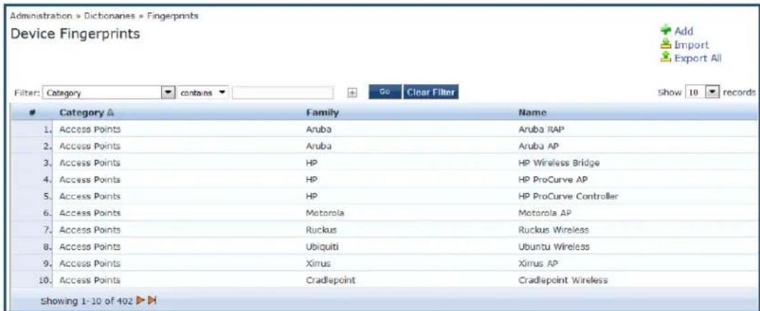
- To drill down and view additional details about the category, click on a line in the Device Fingerprints The Device Fingerprint Dictionary Attributes page opens.
Figure 692: Device Fingerprint Dictionary Attributes Page
![Device Fingerprint Dictionary Attributes Category: Access Points Family: HP Name: HP ProCurve AP Field Value 1. DHCP Option55 [1,28,2,3,15,6,12,43, 1,121,3,6,15,33,43,138] 2. DHCP Option60 [Colubris-AP, [HP, MSM]] 3. SNMP System Description [[ProCurve, Access, Point], [HP, AP]] Close](/content/2026/05/842116/images/fc8e64d3ec9d6d48fce38c381a6a638d557685679e7804bc5df448ff3a89015f.jpg)
Dictionary Attributes
This section contains the following information:
- Introduction
- Adding a Dictionary Attribute
• Modifying Dictionary Attributes - Importing Dictionary Attributes
- Exporting All Dictionary Attributes
- Exporting Selected Dictionary Attributes
Introduction
The Attributes dictionary page allows you to specify unique sets of criteria for local users, guest users, endpoints, and devices. This information can then be used with role-based device policies for enabling appropriate network access.
To view the contents of the attributes dictionary:
- Navigate to Administration > Dictionaries > Attributes.
The dictionary Attributes page opens:
Figure 693: Dictionary Attributes Page
![Administration > Dictionaries > Attributes Attributes Filter: Name contains Go Clear Filter Show 10 records Name A Entity Data Type Is Mandatory Allow Multiple 1. AD Membership Endpoint String No Yes 2. [airgroup_unable] GuestUser String No No 3. [airgroup_shared] GuestUser String No No 4. [airgroup_shared_group] GuestUser String No No 5. [airgroup_shared_location] GuestUser String No No 6. [airgroup_shared_role] GuestUser String No No 7. [airgroup_shared_time] GuestUser String No No 8. [airgroup_shared_user] GuestUser String No No 9. [blacklisted App] Endpoint Boolean No No 10. [Calling-Station-ID] Endpoint MACAddress No No Showing 1-10 of 69 Export Delete](/content/2026/05/842116/images/765584736f3b80a7289dbdd2f6f7d7b3388b6ea5aa2bc5a3026ee0abaf5561f5.jpg)
Table 372 describes the dictionary Attributes parameters:
Table 372: Dictionary Attributes Parameters
| Parameter | Action/Description |
| Filter | Use the Filter drop-down list to create a search based on the Name, Entity, Data Type, Is Mandatory, or Allow Multiple settings. |
| Name The name of the attribute. | |
| Entity Indicates whether the attribute applies to a Local User, Guest User, Device, or Endpoint. | |
| Data Type Indicates whether the data type is String, Integer, Boolean, List, Text, Date, MAC address, or IPv address. | |
| Is Mandatory | Indicates whether the attribute is required for a specific entity. |
| Allow Multiple | Indicates whether multiple attributes are allowed for an entity. |
Adding a Dictionary Attribute
To add a dictionary attribute:
- From the Attributes page, click Add.
The Add Attribute dialog appears.
Figure 694: Add Attribute Dialog
![Add Attribute Entity GuestUser Name [vendor] Data Type String Is Mandatory Yes No Allow Multiple Yes No Default Value (optional) conferenceroom (Enter String without special characters e.g., firstfloor) Add Cancel](/content/2026/05/842116/images/5b85945654e1358b3715178564de29ab996f572a0a33fb23a6ed3e3f5ae69743.jpg)
- Specify the Add Attribute parameters as described in the following table, then click Add.
Table 373: Attribute Setting Parameters
| Parameter Action/Description | |
| Entity Specify whether the attribute applies to a Device, Endpoint, Guest User, Local User, or Onboard. | |
| Name Enter a unique ID for this dictionary attribute. | |
| Data Type From the drop-down, specify the data type. | |
| Is Mandatory Specify whether the attribute is required for a specific entity. | |
| Allow Multiple Specify whether multiple attributes are allowed for an entity.NOTE: Multiple attributes are not permitted if Is Mandatory is specified as Yes. | |
| Default Value Optionally, specify whether the default value is true or false. |
Modifying Dictionary Attributes
To modify dictionary attributes in a service dictionary:
- From the Attributes page, select the dictionary attribute.
The Edit Attribute page opens.
- Make any necessary changes, then click Save.
Importing Dictionary Attributes
To import attributes:
- From the menu at the top right section of the page, click Import.
The Import from File dialog opens.
Figure 695: Importing Dictionary Attributes
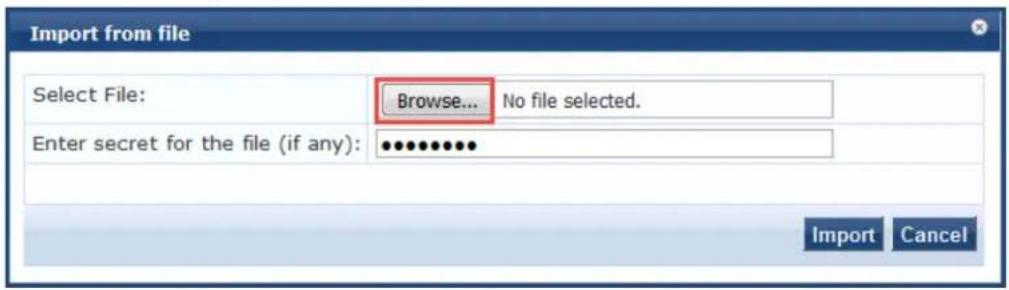
- Enter the Import from File parameters as described in Table 374.
Table 374: Import From File Parameters
| Parameter Description | |
| Select File Browse to select the file that you want to import. | |
| Enter secret for the file (if any) | If the file that you want to import is password protected, enter the se here. |
- When finished, click Import.
The imported file is in XML format. To view a sample of this XML format, export a dictionary file and open it in an XML viewer.

Exporting All Dictionary Attributes
To export all the dictionary attributes at once:
- From the Attributes page, select Export All.
The Export to File dialog opens.
Figure 696: Exporting Dictionary Attributes
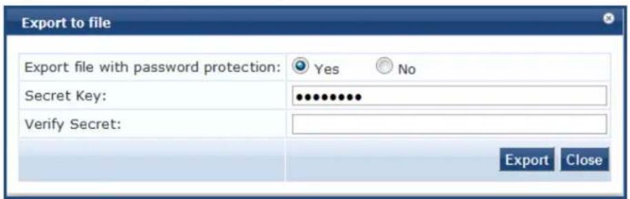
- Specify the Export to File parameters as described in Table 375.
Table 375: Export to File Parameters
| Parameter Action/Description | |
| Export file with password protection | The Yes option is enabled by default.If you wish to disable password protection when exporting a file, selected |
| Secret Key If the file that you want to import is password protected, enter the secret here. Then verify the secret key. | |
- When finished, click Export.
The TagDictionary.xml file is created.
- Download the file.
Exporting Selected Dictionary Attributes
To export selected dictionary attributes:
-
On the Attributes dictionary page, select one or more attribute entries. The Export and Delete buttons on the lower right are now enabled.
-
Click Export.
The Export to File dialog opens.
-
Specify the Export to File parameters as described in Table 375.
-
When finished, click Export.
The TagDictionary.xml file is created.
- Download the file.
Software Updates and OnGuard Settings
This section provides the following information:
• Software Updates on page 693
- OnGuard Settings and OnGuard Custom Web Pages on page 699
• OnGuard Global Agent Settings on page 708
Software Updates
This section provides the following information:
• About Software Updates
• Software Updates Page on page 694
• Install Update Dialog Box on page 696
• Reinstalling a Patch on page 698
• Uninstalling a Skin on page 698
- Updating the Software on page 1
About Software Updates
This section describes the W-ClearPass Policy Manager server software update process.
Use the Software Updates page to register for and receive live updates for:
• Posture updates, including antivirus, antispyware, and Windows updates
• Profile data updates, including Fingerprints
• Software upgrades for the W-ClearPass family of products
■ Patch binaries, including Onboard, Guest plug-ins, and skins
You can also:
- Reinstall a patch in the event the previous installation attempt fails.
- Uninstall a skin.
The W-ClearPass Policy Manager checks for available updates to the W-ClearPass Webservice server. The administrator can download and install these updates directly from the Software Updates page. The first time the Subscription ID is saved, W-ClearPass Policy Manager performs the following:
- Contacts the Webservice to download the latest Posture & Profile Data updates.
- Checks for any available firmware and patch updates.
Software Updates Page
To update the software on the current W-ClearPass server:
- Navigate to Administration > Agents and Software Updates > Software Updates.
Figure 697 displays the Software Updates page:
Figure 697: Software Updates Page
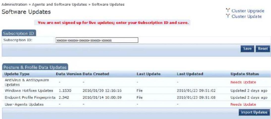
To manually import Posture & Profile Data Updates, refer to Help for this page.

Table 376 describes the Software Updates parameters:
Table 376: Software Updates Parameters
| Parameter | Action/Description |
| Subscription ID | |
| Subscription ID | 1. Enter theSubscription IDprovided to you.This text box is enabled only on a Publisher node. You can opt out of automatic downloads at any time by saving an empty Subscription ID. |
| Save | 2. To save theSubscription ID, click Save.This button is enabled only on a Publisher node. |
| Reset Performs an "undo" of any unsaved changes you have made in theSubscription ID field.NOTE: Reset does not clear the text box. | |
| Posture & Profile Data Updates | |
| Import Updates | If this W-ClearPass Policy Manager server is not able to reach the Webservice server, useImport Updatesto import (upload) the Posture and Profile Data into this server.3. You can download the data from the Webservice server by accessing the following URL:https://clearpass.dell-pcw.com/cppm/appupdate/cppm_apps_updates.zip4. When prompted for authentication credentials, enter the provided Subscription ID for both the username and the password.NOTE: In a W-ClearPass cluster, theImport Updatesoption is available on the Publisher node only. |
| Firmware & Patch Updates | |
| Import Updates | 5. If the server is not able to reach the Webservice server, clickImport Updatesto import the latest signed Firmware and Update patch binaries (obtained via support or other means) into this server.These patch binaries will appear in the table and can be installed by clicking theInstallbutton. When logged in asappadmin, you can manually install the Upgrade and Patch binaries imported via the CLI using the following commands:■system update(for patches)■system upgrade(for upgrades)If a patch requires a prerequisite patch, that patch'sInstallbutton will not be enabled until the prerequisite patch is installed. |
| Install TheInstallbutton appears after the update has been downloaded.6. ClickInstall.When you clickInstall, the installation of the update starts and theInstall Updatesdialog box appears, showing the log messages that are generated. | |
| Re-Install | 7. ClickRe-Installto reinstall a patch in the event the previous attempt to install fails. Reinstalling a patch is available only for the last installed patch. |
| Uninstall | 8. To uninstall a skin, click Uninstall (for details, see Uninstalling a Skin).NOTE: You cannot uninstall cumulative or point patch updates. |
| Needs Restart | The Needs Restart link appears when an update needs a reboot of the server in order to complete the installation.Clicking this link displays the Install Update dialog box, which shows the log messages generated during the installation. |
| Installed | The Installed link appears when an update has been successfully installed. Clicking this link displays the Install Update dialog box, which shows the log messages generated during the installation. |
| Install Error | This link appears when an update install encounters an error. Clicking this link displays the Install Update dialog box, which shows the log messages generated during the install. |
| Other | |
| Check Status Now | Click this button to perform an on-demand check for available updates.Check Status Now applies to updates only on a publisher node, as well as Firmware & Patch Updates. |
| Delete Use this option to delete a downloaded update. | |
The Firmware & Patch Updates table shows only the data that is known to webservice or imported using; Import Updates button.
Install Update Dialog Box
The Install Update dialog box shows the log messages generated during the installation of an update. This dialog appears when you click the Install button.
If the dialog is closed, you can bring it up again by any one of the three following methods:
- Clicking the Install in progress... link while the installation is in progress.
- Clicking the Installed, Install Error link.
- Clicking the Needs Restart link when the installation is completed.
The following figure displays the Install Update dialog box:
Figure 698: Install Update Dialog Box
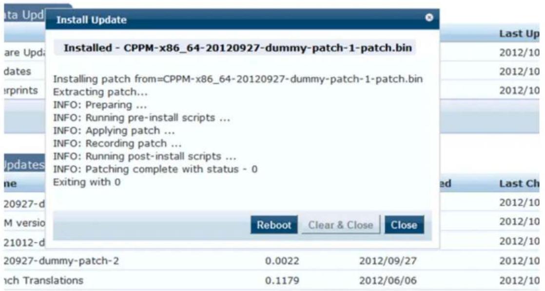
The following table describes the Install Update parameters:
Table 377: Install Update Parameters
| Parameter | Action/Description |
| Reboot 1. To | initiate a reboot of the server, click Reboot.The Reboot button appears only for updates that require a reboot to complete the installation. |
| Clear & Close | 2. To delete the log messages and close the dialog, click Clear & Close.Clear & Close also removes the corresponding row from the Firmware & Patch Updates table.To delete the log messages from a failed installation, click Clear & Close.3. After the log messages are cleared, attempt the installation again. |
| Close 4. To | close the dialog box, click Close. |
Webservice Operations
System Events (as seen on the Monitoring > Event Viewer page) show records for events, such as communication failures with Webservice, successful or failed download of updates, and successful or faile installation of updates.
The W-ClearPass Policy Manager server contacts the Webservice server every hour in the background to download any newly available Posture & Profile Data updates. The current list of firmware and patch up is queried from Webservice every day at a random minute between 4:00 a.m and 5:00 a.m.
Any new list of firmware and update patches that are available are noted by the Policy Manager server automatically and shown in the user interface that they are available for download and installation.
The Webservice itself is refreshed with the Antivirus and Antispyware data hourly, with Windows Updates Fingerprint data and Firmware & Patches are refreshed as and when new ones are available.
An event is generated and displayed in the Event Viewer with the list of new updates that are available.
If the event affects an SMTP server, Alert Notification email addresses are configured, and an email from Publisher node is sent with the list of downloaded images.
Reinstalling a Patch
The Reinstall Patch feature allows the administrator to reinstall a patch in the event the previous attempt to install fails.
You can only reinstall the last installed patch, which is indicated by a "!" symbol next to it in the Firmw Patch Updates table on the Administration > Agents and Software Updates > Software Updates page.
To reinstall a patch or software update:
- Navigate to Administration > Agents and Software Updates > Software Updates.
- In the Firmware & Patch Updates section, click the Installed, Install Error, or Needs Restart link.
- To reinstall the patch or software update, click Re-Install.
The Install Update screen closes and the reinstallation process begins. A window displays, showing the installation progress via log messages.
Uninstalling a Skin
To uninstall a skin:
- Navigate to Administration > Agents and Software Updates > Software Updates.
- In the Firmware & Patch Updates section, select the installed skin that you want to uninstall.
Figure 699: Viewing the Installed Link for a Skin
| Guest Skin | Accenture v2 Skin | 1.0.1-0 | 1.3173 | 2016/08/10 | 2016/09/08 23:21:18 | Download | - |
| Guest Skin | Gartner Skin | 0.1.6-0 | 0.2923 | 2013/10/01 | 2016/09/08 23:21:18 | Download | - |
| Guest Skin | Wi-Fi Alliance Skin | 1.0.0-0 | 0.3722 | 2014/05/21 | 2016/09/08 23:21:57 | Installed | - |
| Import Updates |
- Click the Installed link.
The Install Update dialog opens.
Figure 700: Install Update Dialog
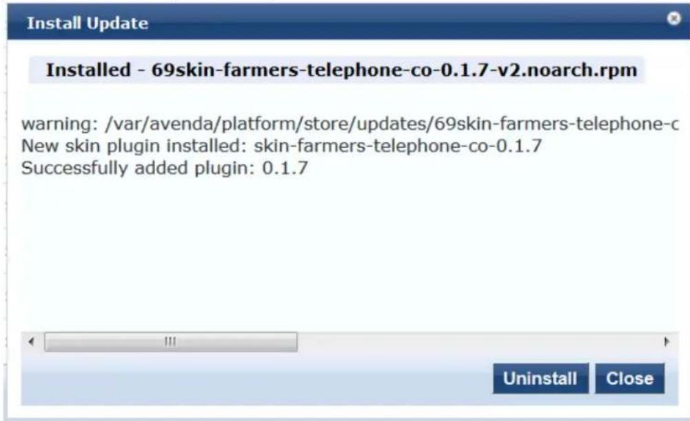
- To uninstall the skin, click Uninstall.
The Install Update screen closes and the software is uninstalled.
OnGuard Settings and OnGuard Custom Web Pages
This section provides the following information:
- Introduction
- About the OnGuard Custom Interface and the Remediation Process
- Configuring OnGuard Settings
- Creating OnGuard Custom Web Pages
Introduction
Use the OnGuard Settings page to configure the agent deployment packages.
When you save the OnGuard configuration, W-ClearPass creates agent deployment packages for the Wind and Macintosh OS X operating systems and provides the packages at a fixed URL on the W-ClearPass Pc Manager hardware or virtual appliance.
You can then publish this URL to the user community or download the agent deployment packages to a location.
To view the OnGuard Support Charts, see Accessing the OnGuard Support Charts on page 739.
About the OnGuard Custom Interface and the Remediation Process
OnGuard provides the ability to show end users a custom interface, or wizard, that guides them through remediation process if their device is quarantined.
When this feature is enabled and OnGuard needs to run a custom remediation script, the wizard tells the why the device was denied network access, describes the tasks that are required to fix the problem, and
the user choose whether to execute the remedial script or not. While the script is being executed and r health checks are run, progress messages are displayed.
The pages of the wizard are created using W-ClearPass Guest's Web Pages configuration forms, and can customized with logo, text, and images (for details, refer to the Custom User Interface parameter in Table 378 and Creating OnGuard Custom Web Pages).
Enabling the Custom User Interface
To enable configuration of the custom user interface and use the options in the Agent Remediation User Interface Customization area, see the next section, Configuring OnGuard Settings.
Creating Custom Web Pages
To create and design the custom web pages the end user sees, use the options provided in the Agent Remediation User Interface Customization area, see Creating OnGuard Custom Web Pages on page 702.
Configuring the Show Custom User Interface for Custom Scripts Attribute
To configure the Show Custom UI for Custom Scripts attribute:
-
Navigate to Configuration > Enforcement > Profiles, then select the Agent Script Enforcement profile.
-
Specify the Success Message, Failure Message, Progress Message, and Description attributes, as well as other script-related attributes (for details, see Configuring Agent Script Enforcement Attributes on page 381).
Configuring OnGuard Settings
To configure the OnGuard settings:
- Navigate to Administration > Agents and Software Updates > OnGuard Settings. The OnGuard Settings page opens:
Figure 701: OnGuard Settings Page
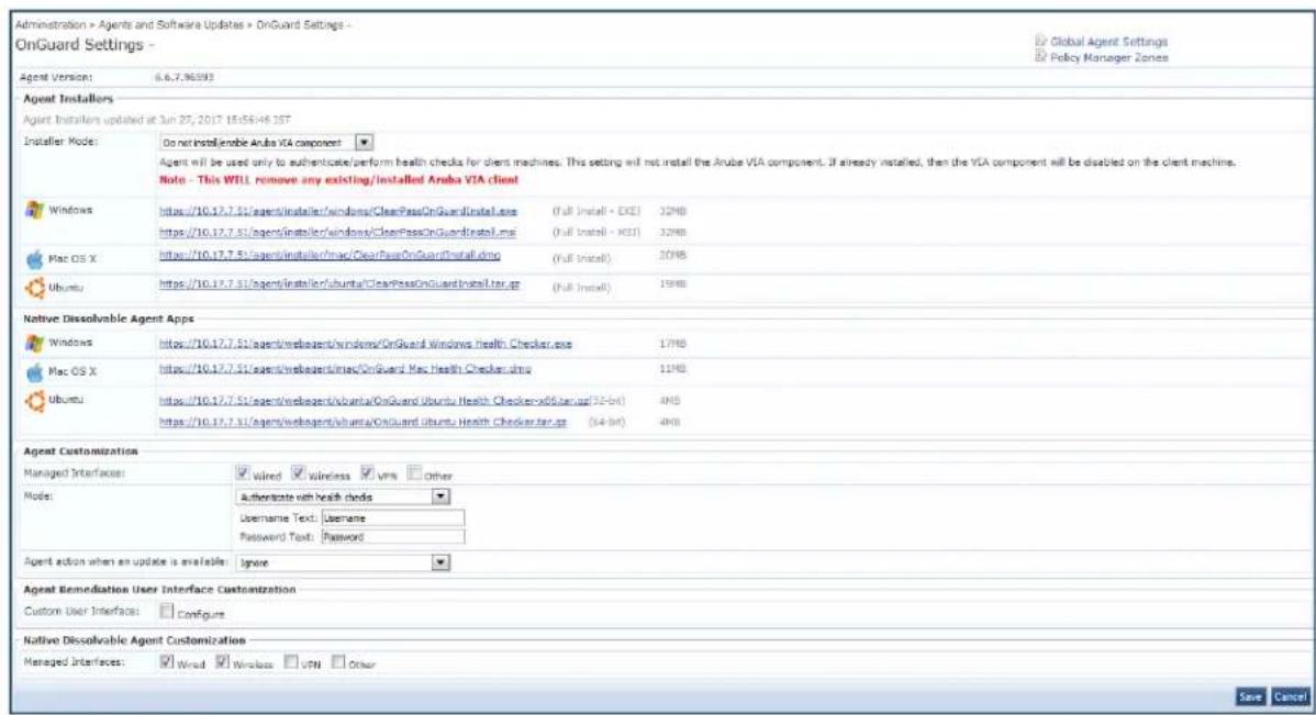
- Configure the OnGuard Settings parameters as described in Table 378, then click Save.
Table 378: OnGuard Settings Parameters
| Parameter Action/Description | |
| Global Agent Settings | Configure the global agent settings parameters for OnGuard agents.For more information, seeOnGuard Global Agent Settings on page 708. |
| Policy Manager Zones | Configure the network (subnet) for a Policy Manager Zone.For more information on configuring Policy Manager zones, see Managing Policy Manager Zones on page 541. |
| Agent Version Indicates the current version of the OnGuard agent. | |
| Agent Installers | |
| Installer Mode | Specify the action to be taken from the following options when the Dell VIA compo used to provide VPN-based access:Do not install/enable Aruba VIA componentInstall and enable Aruba VIA component |
| Windows Use the download link to download OnGuard Agent for Windows.NOTE: This binary file is provided in .exe and .msi formats. | |
| Mac OS X Use the download link to download OnGuard Agent for Mac OS X.NOTE: This binary file is in .DMG format. | |
| Ubuntu Use the download link to download Ubuntu Agent for Linux.NOTE: This binary file is in .tar.gz format. | |
| Native Dissolvable Agent Apps | |
| Windows Click the URL to download Native Dissolvable Agent for Windows. | |
| Mac OS X Click the URL to download Native Dissolvable Agent for Mac OS X. | |
| Ubuntu Click the URL to download Native Dissolvable Agent for Ubuntu.NOTE: You can download the .tar.gz files specific to 32-bit and 64-bit systems. | |
| Agent Customization | |
| Managed Interfaces Select the type(s) of interfaces that OnGuard will manage on the endpoint. Select from following options:WiredWirelessVPNOther | |
| Mode | Select one of the following options:Authenticate - no health checks: OnGuard collects username/password but does not perform health checks on the endpoint.Check health - no authentication: OnGuard does not collect username/password.Authenticate with health checks: OnGuard collects username/password and also performs health checks on the endpoint.Usage/Password Text:The label for the Username and Password fields on the OnGuard agent.NOTE: This setting is not valid for the Check health - no authentication mode. |
| Username Text | The label for the Username field on the OnGuard agent. This setting is not valid for the Check health - no authentication mode. |
| Password Text | The label for the Password field on the OnGuard agent. This setting is not valid for the Check health - no authentication mode. |
| Agent action when an update is available | Determines what the agent does when an update is available.Select one of the following options:Ignore: W-ClearPass Policy Manager ignores the available update.Notify User: W-ClearPass Policy Manager notifies the user that an update is available.Download and Install: W-ClearPass Policy Manager automatically downloads and installs an update when it is available. |
| Agent Remediation User Interface Customization | |
| Custom User Interface | When you select the Configure check box, the Agent Remediation User Interface Customization dialog opens (see Figure 703):Web Pages: To create the OnGuard custom web pages and define the properties for the web pages, click the Create link for the corresponding web page (for details, see the next section, Creating OnGuard Custom Web Pages). |
| Native Dissolvable Agent Customization | |
| Managed Interfaces | The Native Dissolvable Agent performs health checks for one of the selected interfacesThis feature ensures that, if both wired and wireless interfaces are connected, the OnGuard Agent will send health requests through the correct interface.Select the type(s) of managed interfaces that are supported for the Native Dissolvable Agent.Select from the following options:WiredWirelessVPNOther |
Creating OnGuard Custom Web Pages
• HTML Content for OnGuard Custom Web Pages
- Important Points
- OnGuard Custom Script Exit Codes
To create the OnGuard custom web pages:
-
Navigate to Administration > Agents and Software Updates > OnGuard Settings.
The OnGuard Settings page opens. -
Scroll down to the Agent Remediation User Interface Customization section.
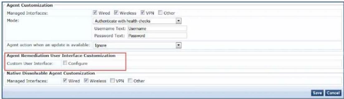
- To enable the Custom User Interface configuration dialog, click (enable) the Configure check box.
Figure 702: Agent Remediation User Interface Customization Dialog
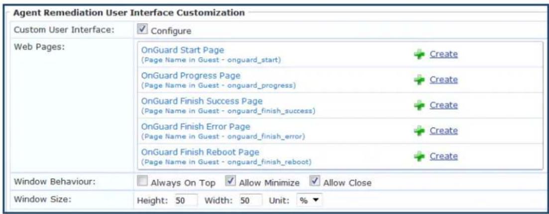
- Click the Create link for the OnGuard custom web page you want to create. For details, see HTML Content for OnGuard Custom Web Pages on page 705. The Create Web Page (New) > Web Page Settings configuration dialog opens.
Figure 703: Configuring a New OnGuard Custom Web Page
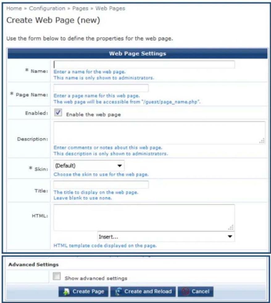
- Specify the required parameters (Name, Page Name, and Skin, as well as Title if desired), then click Create Page.
The OnGuard custom web page is created.
- Window Behavior:
■ Always on Top: The custom user interface window will always be on top of any other windows present.
- Allow Minimize: When set to True, the custom user interface window can be minimized.
- Allow Close: Prevents users from closing the custom user interface window. If set to True, users will be allowed to close the custom custom user interface window; however, the execution of custom scrip continue in the background.
Even if the Allow Close option is enabled, OnGuard Agent disables the Close button of the custom custom user interface while it is loading a page.
- Window Size: Specify the window height and width, as well as whether the window size should be a percentage of the the client's screen or defined by the size in pixels.

HTML Content for OnGuard Custom Web Pages
- OnGuard Start Page
- OnGuard Progress Page
• OnGuard Finish Success Page - OnGuard Finish Error Page
• OnGuard Finish Reboot Page
This section provides the required names for each OnGuard custom web page as well as the recommend HTML content.
Be sure to use the Page Names specified here as W-ClearPass Policy Manager and OnGuard Agent look for pages with these names. Text in italics should not be changed.
OnGuard Start Page
The OnGuard Start Page is the initial web page shown to the end user when script execution begins. The might include a Next button.
Page Name: onguard_start
HTML:
<p>Your device does not meet Minimum Specifications, which is required before you can connect to the Network.</p>
<p>The following is required:</p>
<div id="tasks_list">
</div>
<p>Please click the Next button below to start the remediation needed.</p>
<p>You will be connected to the Network after verification that your device meets all Minimum Security Specifications.</p>
<p><button id="next_button" type="button" onclick="" /> Next</button></p>
If the Next button is missing on the OnGuard Start Page, OnGuard Agent will move to the OnGuard Progress Page after 30 seconds. This time duration is not configurable.

OnGuard Progress Page
The OnGuard Progress Page shows the progress and status of custom scripts that are being executed.
Page Name: onguard_progress
HTML:
<p>Please do not disconnect your device.</p>
<div id="task_progress_list">
</div>
OnGuard Finish Success Page
The OnGuard Finish Success Page is shown after all the scripts have executed successfully and a system is not necessary. This page includes a Close button.
Page Name: onguard_finish_success
HTML:
We will now rescan your system to verify that it meets Minimum Security Specifications and then cor you to the Network.
If you are not connected in five minutes, please contact 12334 or click here .
Close
OnGuard Finish Error Page
The OnGuard Finish Error Page is shown if at least one of the scripts returns Failure and a reboot is not required. This page includes a Close button.
Page Name: onguard_finish_error
HTML:
Remediating your device to meet Minimum Security Specifications was unsuccessful because:
Please visit this Support Page to get assistance.
You are not yet connected to the Network.
Close
OnGuard Finish Reboot Page
Page Name: onguard_finish_reboot
The OnGuard Reboot Page is shown after all the scripts have executed successfully and a system reboot necessary. This page includes a Reboot button.
HTML:
We will now rescan your system to verify that it meets Minimum Security Specifications and rebo your system, then connect you to the Intel Network.
If you are not connected in five minutes, please contact 12334 or visit this Support Page to get assistance.
Reboot
Important Points
This section provides important notes regarding OnGuard Agent behavior when using the Custom User Interface for Custom Scripts.
In ClearPass Policy Manager 6.6.7, this feature is supported for Windows Persistent Agent only.

- OnGuard Agent checks the custom script's exit code to compute the custom scripts status.
- OnGuard Agent determines the final page based on the script's exit codes and the client's health status. For details, see the next section, OnGuard Custom Script Exit Codes on page 707.
- This feature is not supported when OnGuard is running as a service.
- The custom user interface loads a fresh web page from W-ClearPass Guest every time. It does not cap pages.
-
If the user closes the custom user interface while the script is executing, OnGuard Agent continues executing scripts without the custom user interface.
-
Administrators will have to refresh or open the OnGuard Settings page again after creating web pages in W-ClearPass Guest (Administration > Agents and Software Updates > OnGuard Settings).
- If the W-ClearPass Server Certificate is not validated when W-ClearPass loads the web page for the first the custom user interface displays the following security alert:
Figure 704: Server Certificate Not Validated Security Alert
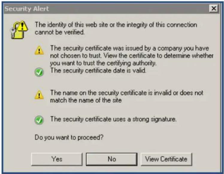
- A new option, Server Communication Mode, has been added in Global Agent Settings that you can configure to avoid receiving a Server Certificate security alert (see the Server Communication Mode parameter description in Global Agent Settings Parameters for OnGuard Agents on page 709).
OnGuard Custom Script Exit Codes
The OnGuard custom script exit codes are comprised of Success Codes and Failure Codes as described below:
Success Codes (0 to 63)
The range available to Administrators to define their own Success Codes = 3 (0x03) to 63 (0x3F).
- Script executed successfully = 0 (0x00)
• Reboot (Reboot is required) = 2 (0x02)
Failure Codes (65 to 255)
The range available to Administrators to define their own Failure Codes = 65 (0x41) to 255 (0xFF).
- Script executed successfully but its exit code indicates failure = 64 (0x40)
OnGuard Agent Codes (256 onwards):
• Unknown error = 256 (0x100)
- Timeout: Script did not finish execution in expected time = 257 (0x101)
- Failed to read exit code of script = 258 (0x102)
- OnGuard failed to execute script = 259 (0x103)
- Script file not found = 260 (0x104)
- Script file did not pass validation checks = 261 (0x105)
• Failed to download script file = 262 (0x106)
- Execution level is set to "User" but the user is not logged on, so OnGuard was not able to launch the script = 263 (0x107)
OnGuard Global Agent Settings
This section provides the following information:
• About Global Agent Settings
• Global Agent Settings Parameters for OnGuard Agents
• Global Agent Settings: Run OnGuard As Parameter
About Global Agent Settings
Use the Global Agent Settings page to configure the global parameters for OnGuard agents.
- Navigate to the Administration > Agents and Software Updates > OnGuard Settings page.
- Click the Global Agent Settings link at the top-right corner.
The Configure Global Agent Settings page opens.
Figure 705: Configure Global Agent Settings Page
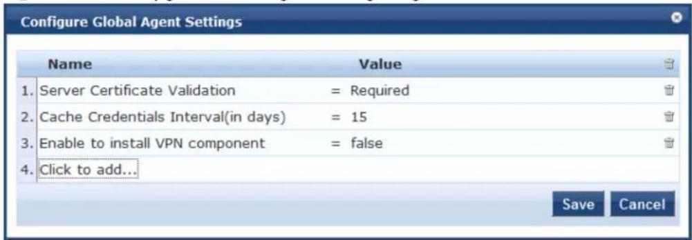
- To add additional Global Agent Settings parameters, select Click to add...
- Name: Select the desired Global Agent Setting (see Table 379).
- Value: Specify the appropriate value.
- Repeat these steps as necessary for each additional setting, then click Save.
Global Agent Settings Parameters for OnGuard Agents
Table 379 describes the Global Agent Settings parameters for OnGuard agents:
Table 379: Configure Global Settings Parameters
| Parameter Action/Description | |
| Name | Allowed Subnets for Wired access: Add a comma-separated list of IP addresses or subnet addresses. |
| Allowed Subnets for Wireless access: Add a comma-separated list of IP addresses or subnet addresses. | |
| Cache Credentials Interval (in days): Select the number of days the user credentials should be cached on OnGuard agents. | |
| Delay to bounce after Logout (in minutes): Specify the number of minutes that should elapse before OnGuard bounces the interface if OnGuard remains disconnected. | |
| Enable OnGuard requests load-balancing: Enable this option to balance the load of OnGuard authentication requests across W-ClearPass Policy Manager servers in a cluster. | |
| Enable access over Remote Desktop Session: Enable this option to allow OnGuard access through a Remote Desktop session. | |
| Enable to hide Logout button: Enable this option to hide the Logout button on OnGuard agent. | |
| Enable to install VPN component: Enable this option to install the OnGuard VPN component. | |
| Enable to use Windows Single-Sign On: Enable this option to allow use of a user's Windows credentials for authentication. | |
| Keep-alive Interval (in seconds): Specify a keep-alive interval for OnGuard agents. The connected OnGuard Agents periodically send heart-beat (Keep-Alive) messages to W-ClearPass Policy Manager. This interval is defined by the Keep-alive Interval (in seconds) parameter. The default value is 60 seconds.W-ClearPass uses Keep-Alive messages to:Update the status of OnGuard Agents regarding OnGuard Activity.Issue CoA (Change of Authorization) for a Session Restrictions Enforcement Profile if OnGuard Agent is disconnected:Session-Check > Agent-Connection = DownPost-Auth-Check > Action = DisconnectFor related information, see Session Restrictions Enforcement Profile on page 413. | |
| OnGuard Health Check Interval (in hours): Specify the number of hours that OnGuard will skip health checks for healthy clients.NOTE: Note the following information when you set the OnGuard Health Check Interval parameter:Set this parameter if OnGuard mode is set to health only.This parameter is valid only for wired and wireless interface types.This parameter is not applicable for the OnGuard Dissolvable Agent, VPN, and Other interface types.You can also specify the health-check interval in the Agent Enforcement profile (Configuration> Enforcement > Profiles > Add) to create different Agent Enforcement Profiles for different users. | |
| Run OnGuard As: For details, see the next section, Global Agent Settings: Run OnGuard As Parameter. | |
| Server Certificate Validation: Enables the W-ClearPass OnGuard Unified Agent to validate the W-ClearPass Server Certificate when it sends a WebAuth health request to W-ClearPass. | |
| Server Communication Mode: Based on the value of this attribute, OnGuard Agent will IP address, HostName, or FQDN (Fully Qualified Domain Name) to communicate with the W-ClearPass server.Select one of the following values:IPHostnameFQDN | |
| Support Team Email Address: Enter an email address that automatically populates the To field in the user's email client when they send logs. | |
| Use Current OS Language (Windows Only): Enables W-ClearPass OnGuard Agent to use the current user's display language, if supported, overriding the language selected at installation time. This parameter applies only to Windows clients. | |
| Value Enter the | value for the parameters selected in the Name drop-down. |
Global Agent Settings: Run OnGuard As Parameter
You can configure OnGuard to run health checks even if a user is not logged in.
- Navigate to Administration > Agents and Software Updates > OnGuard Settings.
The OnGuard Settings page appears.
- Click Global Agent Settings.
The Global Agent Settings dialog appears.
Figure 706: Global Agent Settings Dialog
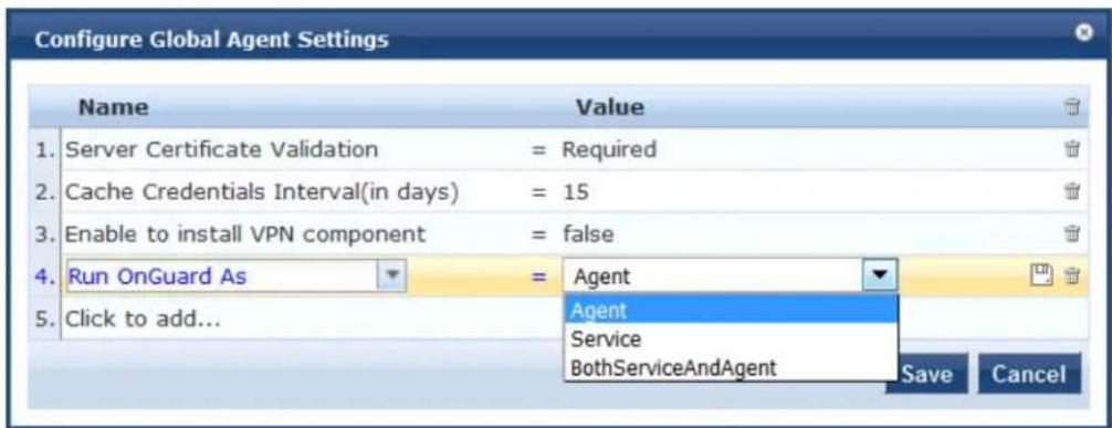
- Click Click to add...
-
Name: Select Run OnGuard As.
-
Value: Select the appropriate option as described in Table 380.
Table 380 describes the available values for the Run OnGuard As parameter.
- Click Save.
Table 380: Global Agent Settings: Run OnGuard As Parameters
| Value Description | |
| Agent Health checks are performed by the OnGuard Agent after the user logs in to the client. | |
| Service OnGuard | Agent performs health checks as soon as the client boots up, that is, even before the user logs in to the client.When a user logs in to the client, the user can view the most recent health check results via the OnGuard Agent user interface. The user can perform health checks again by clicking the button. For details, see the next section, Limitations for the Run OnGuard As Parameter. |
| BothService AndAgent | When the user is not logged in to the client, the ClearPass OnGuard Agent service performs health checks. As soon as the user logs in to the client, the W-ClearPass OnGuard Agent stops health checks and the OnGuard Agent user interface initiates health checks. |
Limitations for the Run OnGuard As Parameter
When the Run OnGuard As parameter is set to Service, the following limitations pertain:
- In Service mode, OnGuard always runs in Health Only mode; that is, OnGuard always sends the client's MAC Address as User Name.
- If a user is not logged in, some of the health checks and auto-remediation may fail in Service mode. These health checks are user-level checks, such as Registry Keys (HKCU), Processes, and Installed Applications applications).
- When OnGuard Agent is running in Service mode, the OnGuard user interface is used only to display messages and provide the Retry button (to perform health checks).
- The Enable to Hide Quit Option does not have any effect in Service mode as the Quit button is only for exiting the OnGuard user interface.
Using W-ClearPass Dictionaries
This section provides the following information:
• RADIUS Dictionary on page 685
• TACACS+ Services Dictionary on page 686
• Device Fingerprints Dictionary on page 688
• Dictionary Attributes on page 689
• Applications Dictionaries on page 934
- Configuring Endpoint Context Server Actions on page 614
This chapter contains the following information:
- About the Cluster Update Tool
• About the Cluster Upgrade Tool
About the Cluster Update Tool
This section provides instructions for updating a W-ClearPass cluster with Patch and Skin releases using t Cluster Update tool.
The Cluster Update tool automates the process of updating your W-ClearPass cluster. The cluster Publisher node is updated first. You can select one or more Subscriber nodes to be updated automatically after the Publisher update is complete.
After you initiate the Cluster Update, no manual actions are required until the Publisher and all the sele Subscriber nodes have been updated.
This section includes the following information:
• About the Cluster Update Feature
• Before Updating the Cluster
- Updating the Cluster
• Viewing Update Status
About the Cluster Update Feature
The Cluster Update feature performs the following actions:
- Copies the update image to the selected Subscriber nodes.
Subscriber nodes copy the update image over an HTTPS connection to the Publisher.
If you want to avoid the copy on one or more Subscriber nodes, log in to the Subscriber and trigger download of the update image in the Update portal; alternatively, upload the update image through the Update Portal before initiating the cluster update.
- The Publisher is updated and rebooted (reboot is initiated only if it is mandatory).
- After the Publisher update completes, the Update utility will be accessible again to review progress and log messages.
- The Cluster Update is now initiated on the selected Subscriber nodes; after completion, the Subscriber nodes are rebooted (reboot is initiated only if it is mandatory).
- Where possible, multiple Subscriber nodes are updated in parallel.
- After all selected Subscriber nodes have been updated, you can select and trigger a Cluster Update for any additional Subscriber nodes.
Time Required for Subscriber Update
The time required for a Subscriber nodes update depends on the following factors:
- Hardware or Virtual Appliance model. In the case of Virtual Machine installations, update times vary significantly based on the IOPS (I/O per second) performance of your virtual machine infrastructure.
- For Subscriber nodes, bandwidth and latency of the network link between the Subscriber and Publisher.
Before Updating the Cluster
Before updating the W-ClearPass cluster, complete the following tasks:
-
Before starting the Cluster Update, plan for sufficient downtime and review the Release Notes for the current W-ClearPass Policy Manager release.
-
Confirm that Relevant Patch updates are available under software updates before starting the cluster update. Please download the patches either from Webservice or by uploading directly to Software Upc
Only patches listed under Software Updates are shown in the Cluster Update.
-
Confirm that your Cluster sync and replications are fine before starting the Cluster Update.
-
When a particular node's version information is set to "UNKNOWN", it means the Publisher is not able to contact the remote node. (If a node has been disabled and gone out of sync, the Cluster Update Inte might not detect the disabled status until the patch failure has occurred, after which the failed/inaccess node is marked as UNKNOWN).
Confirm the status of the cluster sync and service status of "Async network services" in such cases.
- In virtual machine environments, W-ClearPass Policy Manager Virtual Machine host date/time settings should be in sync with that of the VMware vSphere, Microsoft Hyper-V server, or KVM hypervisor that hosting the instance. Otherwise, you might see inconsistent data in "Time Taken" columns of the Update Interface.
Updating the Cluster
To update the cluster:
- Navigate to Administration > Agents and Software Updates > Software Updates > Cluster Update.
Figure 707: Cluster Update
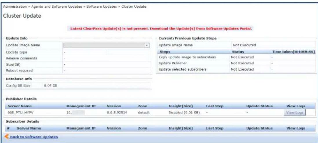
- Before you start the update, verify that the W-ClearPass update is downloaded and available in the Software Updates portal. If the update is not available, the Cluster Update page displays the following message advising you to download it:
Latest ClearPass Update(s) is not present. Download the Update(s) from Software Updates Portal.
- If you are prompted to log in, use your W-ClearPass Policy Manager administrator credentials. The Cluster Update page opens.

Figure 708: Cluster Update Page
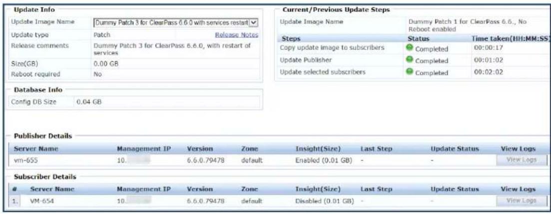
This page includes the information described below in Table 381.
Table 381: Information on the Cluster Update Page
| Field Description | |
| Update Info | Describes the patch update details, provides a link to the Release Notes, includes release-specific comments, and specifies if a reboot is required for the patch. |
| Database Info Shows the | size of the Configuration database. |
| Publisher Details Information | for the Publisher and for all Subscriber nodes in the cluster. Information includes the management IP address, version number, zone, Insight database size, last update step completed, and update status.Subscriber Details |
| Update Steps During the | cluster update, this area shows the status of each stage in the process. As each stage completes, it shows how long it took to complete. |
| View Logs In each Publisher and Subscriber row, this link provides detailed status and log messages for each update stage. | |
- Select the Update Image Name from the drop-down list.
When the update is available locally and all Subscriber nodes have been patched, the Start Update link is available in the upper-right corner.
- Click Start Update.
The Start Cluster Update window opens.
Figure 709: The Start Cluster Update Window
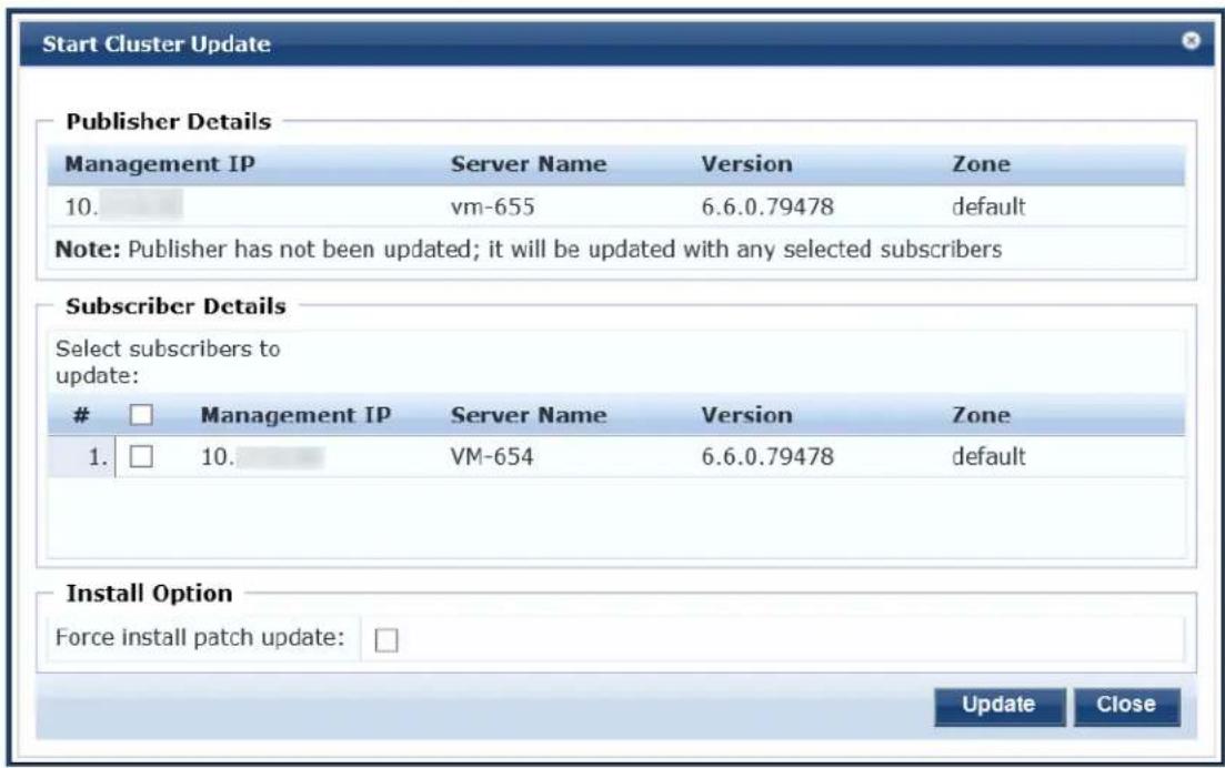

You can update the entire cluster or just a subset of Subscriber nodes.
- In the Start Cluster Update window, use the check boxes to select the Subscriber nodes to update.
- To force the update, select Force install patch update under Install Option.
- Click Update.
This initiates the automated update process. No further manual steps are required until all selected Subscriber nodes have been updated. The Publisher is always updated and rebooted first.
The Cluster Update page will not be available while the Publisher is rebooted. When the Publisher up complete, you can use the Cluster Update page to monitor update progress.
Viewing Update Status
After the Publisher Update is complete, you can monitor the Update status of the Subscriber nodes at Administration > Agents and Software Updates > Software Updates > Cluster Update.
There are two ways to monitor the update's progress:
- On the Cluster Update page, progress indicators in the Update Steps area show the status of some of the main steps.
Indicators in the Publisher Details and Subscriber Details areas also show when the Publisher or each subscriber is in progress or completed.
When the update is complete, these areas should show a successful update status for the Publisher at every subscriber.
Figure 710: Status Indicators in the Update Steps Area
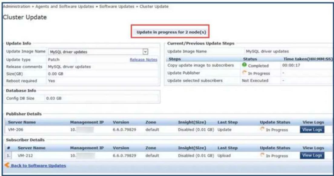
If you navigate to another page, and then navigate back to the Software Updates page, a status link provided.
Figure 711: In Progress Status Link
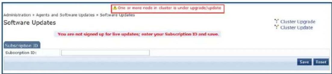
Clicking the link takes you back to the Cluster Update page.
- For detailed progress information, click the View Logs button in the Publisher's or Subscriber's row.
The Logs window opens. This window includes tabs for the Download, Upgrade, Reboot, and Onboot logs.
You can view detailed status in these logs during and after the update.
This option is not available while the Publisher is rebooted and data migration is in progress. It is available again when the Publisher update is complete.

Figure 712: Details Displayed on the Logs Window
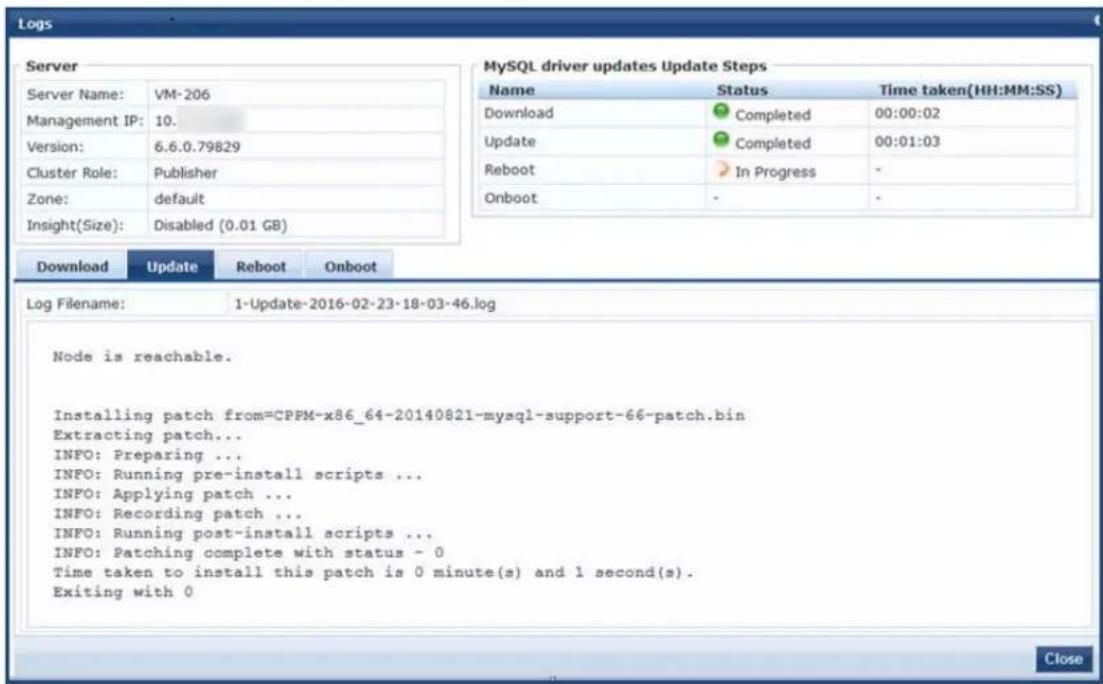
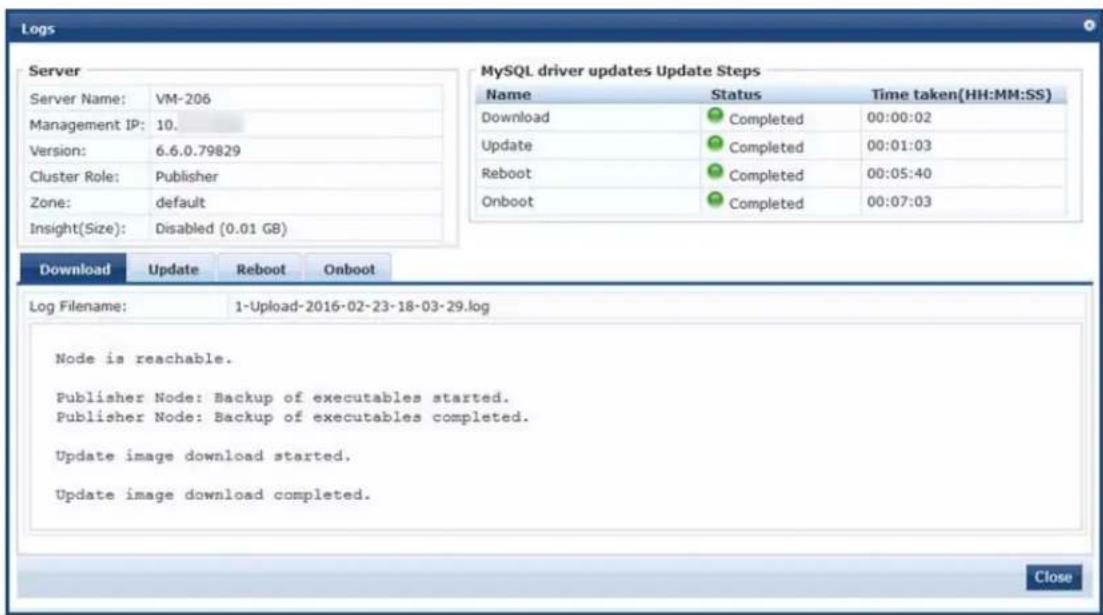
About the Cluster Upgrade Tool
This section includes the following information:
- Cluster Upgrade Process Overview
• Before You Upgrade
• Installing the Cluster Upgrade Tool - Launching the Cluster Upgrade Tool
• Upgrading the W-ClearPass Cluster
• Viewing Upgrade Status
- Steps in the Upgrade Tool's Automated Workflow
- Troubleshooting Tips
Introduction
This section provides instructions for upgrading a W-ClearPass cluster using the Cluster Upgrade Tool.
The Cluster Upgrade Tool is a simple user interface that automates the upgrade procedure for a W-Clear cluster. When the Upgrade is initiated, no manual actions are required until the Publisher and all select Subscribers have been upgraded.
This release of the tool can be used to upgrade W-ClearPass 6.3.6, 6.4.7, 6.5.x, and 6.6.x systems to W-ClearPass 6.6. It cannot be used to upgrade to an earlier version of the Cluster Upgrade Tool.
If you have an earlier version of the Cluster Upgrade Tool already installed, you can install this version of over the earlier version of the tool; no cleanup steps are needed.
Cluster Upgrade Process Overview
These tasks summarize the Cluster Upgrade process:
- Download the upgrade image to the Software Updates Portal.
- Install the Cluster Upgrade Tool (see Installing the Cluster Upgrade Tool).
- Launch the Cluster Upgrade Tool and specify the Subscriber nodes to be upgraded (see Launching the Cluster Upgrade Tool).
- Initiate the Upgrade procedure (see Upgrading the W-ClearPass Cluster).
The Cluster Upgrade tool automatically performs the upgrade. - After the upgrade, verify that the Publisher and all Subscriber nodes in the cluster are back in sync a services are accessible (see Viewing Upgrade Status).
Cloning a virtual machine to facilitate a W-ClearPass deployment is not recommended or supported.

Before You Upgrade
Before you begin the cluster upgrade process, ensure that the following tasks have been completed:
- Review this section and the latest Release Notes for W-ClearPass 6.6.
- Plan for adequate downtime for the upgrade.
Use the upgrade time estimates in Sample Times Required for Upgrade on page 728 as a guide. - Install the Cluster Upgrade Tool on the Publisher node of your 6.3.6, 6.4.7, 6.5.x, and 6.6.x version.
- Before installing the Cluster Upgrade Tool on the Publisher, verify that W-ClearPass services are up an running on both the Publisher and all Subscriber nodes. Verify again after installing the tool.
-
If the cluster password contains special characters, change it temporarily to only use alphanumeric characters (letters and numbers) before installing this patch.
You can change the cluster password back to the old password after the cluster upgrade completes. -
HTTP, HTTPS, and SSH port traffic must be allowed between the cluster nodes. This is required in order to use the tool to be able to communicate between nodes.
Verify that the following ports are in an open state between the cluster nodes:
■ Port 80 (HTTP)
■ Port 443 (HTTPS)
■ Port 22 (SSH)
- Confirm that the Publisher node and all Subscriber nodes in the cluster are in sync before starting the upgrade.
- On the Software Updates page, enter the Subscription ID.
- On the Publisher node, download the W-ClearPass 6.6 upgrade image from the Software Updates portal (see Software Updates and OnGuard Settings on page 693).
The Upgrade tool automates the process of copying over the upgrade image to the selected subscribe the cluster.
- If you are upgrading on a reverted system (retrying an upgrade), you will need to replace the content certain directories first before triggering the new upgrade. Please contact Support (see Contacting Support on page 1), who will assist you with the following tasks:
a. Copying the contents of the /var/avenda/platform/store/updates/backup/* directory to the /var/avenda/platform/store/updates/ directory.
b. Clearing the contents of the /var/avenda/tips/upgrade/db/* directory.
c. Restarting the cpass-admin-server on the Publisher.
- When a particular node's version information is set to "UNKNOWN," it means the Publisher is not able to contact the remote node.
If a node has been disabled and gone out of sync, the Cluster Upgrade interface might not detect that until the patch failure has occurred, after which the failed or inaccessible node is marked as UNKNOW. In such cases, confirm the status of the cluster sync and the service status of Async network services (navigate to the Administration > Server Manager > Server Configuration > Service Parameters page, then select Async network services from the Select Service drop-down).
d. In virtual machine environments, W-ClearPass Policy Manager virtual machine host date and time settings should be in sync with that of the VMware vSphere Hypervisor server, Microsoft Hyper-V or KVM hypervisor server that is hosting the instance. Otherwise, you might see inconsistent data in "Time Taken" columns of the Upgrade interface.
Installing the Cluster Upgrade Tool
The Cluster Upgrade Tool is released as separate patches for each of the W-ClearPass 6.3.6, 6.4.7 and 6. versions. It can be downloaded and installed either through Policy Manager's Software Updates portal or the Dell Support Center (https://download.dell-pcw.com).
The Upgrade Tool can only be installed on the Publisher node.

To install the Upgrade Tool through the Software Updates Portal:
- Log in to W-ClearPass Policy Manager on the Publisher and navigate to Administration > Agents and Software Updates > Software Updates.
- If you have not already entered the Subscription ID, do so now.
- In the row for the W-ClearPass Cluster Upgrade Tool patch, click the Install button.
When the installation is complete, the Admin service will be restarted. You do not need to reboot.
- To review the Release Notes for the tool, click the patch's row.
The More Information window opens.
- Click the Release Notes URL link.
The Support Center's Release Notes page opens in a new tab.
Figure 713: The Link to the Cluster Upgrade Tool Release Notes
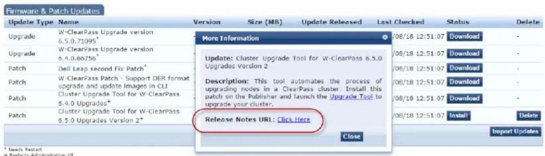
If the Publisher Is Not Set Up
To install the Upgrade Tool if the Publisher is not set up to display available updates:
- On the Dell Support Site (https://download.dell-pcw.com), manually download the Cluster Upgrade Tool.
- On the Publisher's Software Updates portal, use the Import Updates link to upload it.
- Install the Upgrade Tool as described above.
Launching the Cluster Upgrade Tool
After the Cluster Update Tool is installed, you can launch the Cluster Upgrade tool either from the Soft Updates portal or through your Web browser.
To launch the Cluster Upgrade Tool from the Software Updates portal:
- In W-ClearPass Policy Manager, navigate to Administration >Agents and Software Updates >Software Updates.
- In the upper-right of the page, click Cluster Upgrade.
The Cluster Upgrade page opens.
An Alternative Way to Open the Upgrade Tool
An alternative way to open the tool is as follows:
- In W-ClearPass Policy Manager, navigate to Administration >Agents and Software Updates >Software Updates.
- In the Firmware & Patch Updates area, click the row of the W-ClearPass Cluster Upgrade Tool patch.
- In the More Information window that opens, click the Upgrade Tool link.
Figure 714: The Link to the Cluster Upgrade Tool
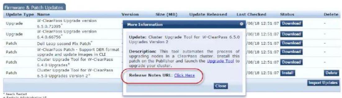
Opening the Tool Via Your Web Browser
To open the Cluster Upgrade Tool directly through your Web browser:
-
Enter https://
/upgrade in your browser's address bar. -
If you are prompted to log in, use your W-ClearPass Policy Manager administrator credentials.
The Cluster Upgrade Utility page opens.
Figure 715: The Cluster Upgrade Utility Page
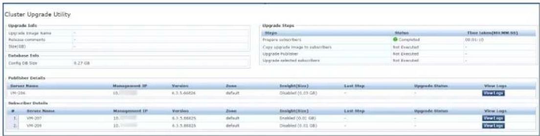
This page includes the information described below in Table 382.
Table 382: Information on the Cluster Upgrade Utility Page
| Field Description | |
| Upgrade Info | Describes the upgrade image's name and size, provides a link to the Cluster Upgrade Tool Release Notes, and includes release-specific comments. |
| Publisher Details | Information for the Publisher and for all Subscriber nodes in the cluster. Information includes the management IP address, version number, zone, Insight database size, last upgrade step completed, and upgrade status. |
| Subscriber Details | |
| Database Info | Shows the size of the Configuration database. |
| Upgrade Steps | During the cluster upgrade, this area shows the status of each stage in the process. As each stage completes, it shows how long it took to complete. |
| View Logs | In each Publisher and Subscriber row, this link provides detailed status and log messages for each upgrade stage. |
| Help Briefly | describes the actions performed by the tool. |
- If the cluster password contains special characters, change it temporarily to only use alphanumeric characters (letters and numbers) before installing this patch.
The cluster password can be changed back to the old password after the cluster upgrade completes
Figure 716: Special Characters Note
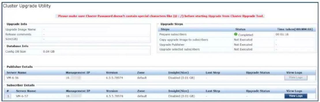
Figure 717: More Information > Special Characters Note
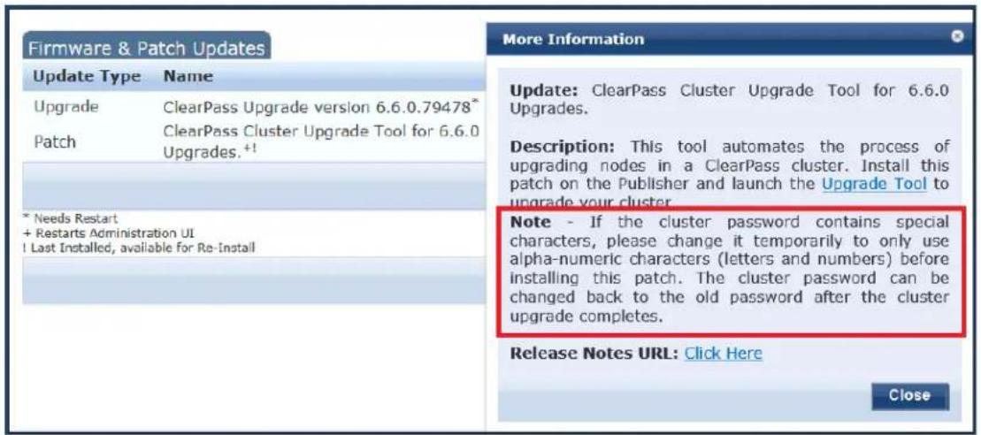
Upgrading the W-ClearPass Cluster
To upgrade the W-ClearPass cluster:
- Navigate to Administration > Agents and Software Updates > Software Updates > Cluster Upgrade.
- Before you start the upgrade, verify that the W-ClearPass 6.6 Upgrade Image is downloaded and available in the Software Updates portal.
If the upgrade image is not available, the Cluster Upgrade page displays a message advising you to download it.
Figure 718: The Message Advising that the Upgrade Image Must Be Downloaded
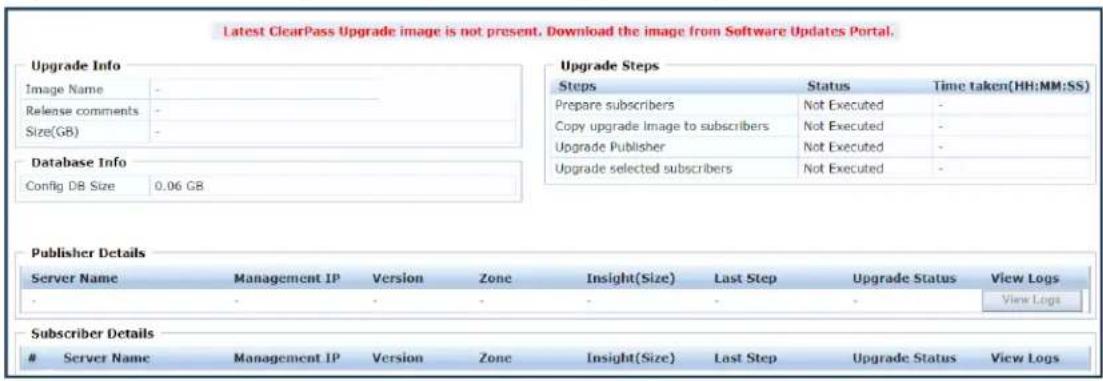
- When you open the Cluster Upgrade Tool, it immediately prepares the subscribers for upgrade by automatically installing the required additional API support.
This is a background process and does not require any actions from the user. A progress indicator shown during this stage.

To install the patch for API support on Subscriber nodes, these nodes must be able to access the Publisher over HTTP, or they must be able to access the publisher over HTTPS using its host name and validate the certificate that is presented (that is, trust the issuer and match the host name in the certificate Common Name (CN)).
When the 6.6 upgrade image is available locally and all Subscriber nodes have been patched, the Start Upgrade link is available (in the upper-right corner).
- Click Start Upgrade.
The Start Cluster Upgrade window opens.
Figure 719: The Start Cluster Upgrade Window
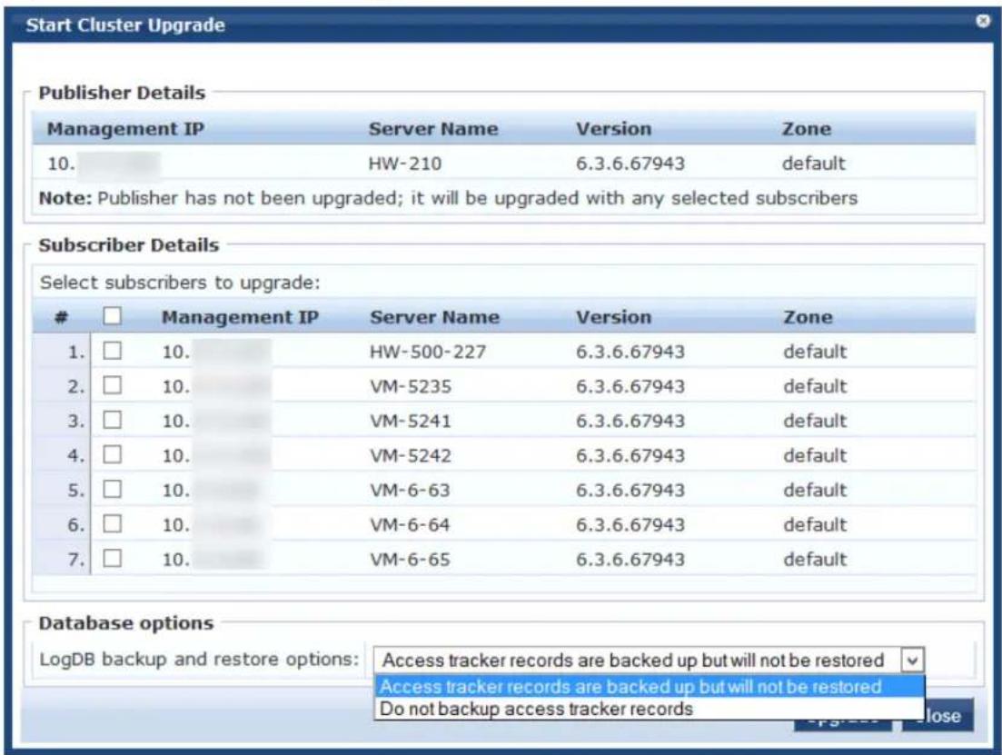
You can upgrade the entire cluster or just a subset of Subscriber nodes.
-
In the Start Cluster Upgrade window, use the check boxes to select the Subscriber nodes to upgrade.
-
In the LogDB backup and restore options drop-down list:
a. If you need a backup of the Access Tracker records to potentially restore after upgrade, select Access tracker records are backed up but will not be restored.
This option will increase the overall upgrade time.
b. If you do not need a backup of the Access Tracker records, select Do not back up access tracker records.
- Click Upgrade.
The Upgrade Tool begins the automated upgrade process.
No further manual steps are required until all selected subscribers have been upgraded. For inform on the automated process, see Steps in the Upgrade Tool's Automated Workflow on page 727.
The Publisher is always upgraded and rebooted first. The Upgrade Tool will not be available while publisher is rebooted and data migration is in progress.
-
When the Publisher upgrade is complete, navigate to the Cluster Upgrade Utility page to monitor upgrade progress, as described in Viewing Upgrade Status on page 726.
-
After a successful upgrade, confirm that all the Subscriber nodes in the cluster are back in sync and the services are accessible.
-
Verify that any preexisting Standby Publisher settings are restored:
Navigate to: Administration >Server Manager >Server Configuration >Cluster-Wide Parameters link >Standby Publisher tab.
Viewing Upgrade Status
After the Publisher Upgrade is complete, you can monitor the Upgrade status of the Subscriber nodes Administration > Agents and Software Updates > Software Updates > Cluster Upgrade.
The tool provides two ways to monitor the upgrade's progress:
- On the Cluster Upgrade page, progress indicators in the Upgrade Steps area show the status of some of the main steps.
Indicators in the Publisher Details and Subscriber Details areas also show when the Publisher or each Subscriber node is in progress or completed.
When the upgrade is complete, these areas should show a successful upgrade status for the Publis and every Subscriber node.
Figure 720: Status Indicators in the Upgrade Steps Area
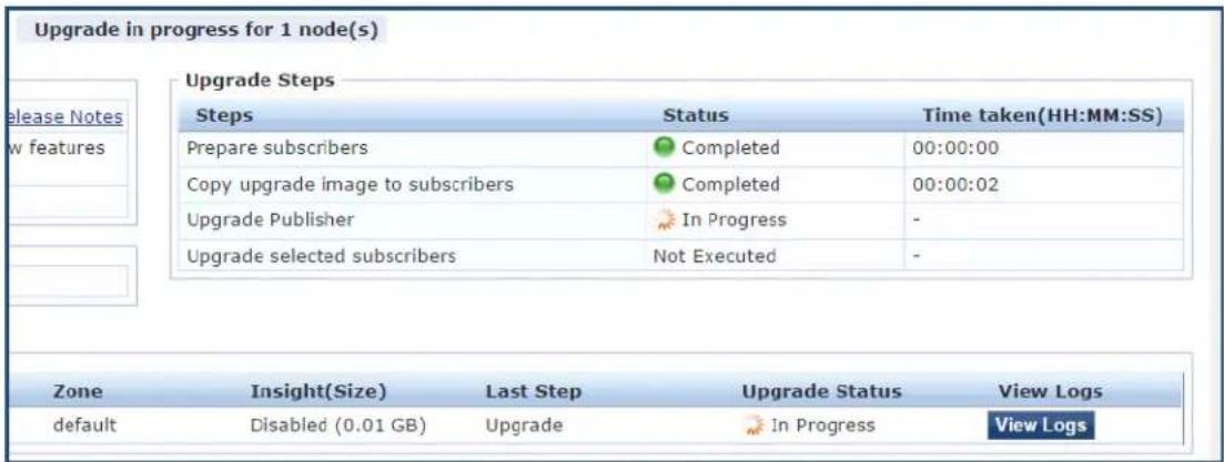
If you navigate to another page, and then navigate back to the Software Updates page, a status lii be provided.
Figure 721: In Progress Status Link
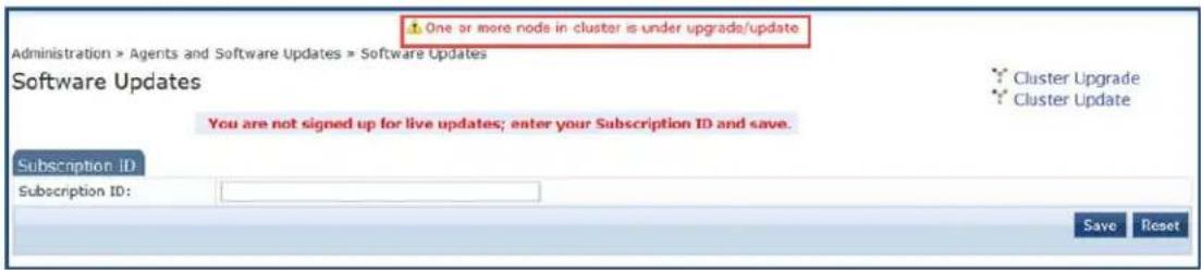
Clicking the link takes you back to the Cluster Upgrade page.
- For detailed progress information, click the View Logs button in the Publisher's or Subscriber's row.
The Logs window opens. This window includes tabs for the Patch, Download, Upgrade, Reboot, and Onboot logs.
You can view detailed status in these logs during and after the upgrade.

This option is not available while the Publisher is rebooted and data migration is in progress. It is available again when the Publisher upgrade is complete.
Figure 722: Details Displayed on the Logs Window
![Logs Server Server Name: VM-207 Management IP: 10. Version: 6.6.0.79478 Cluster Role: Publisher Zone: default Insight(Size): Enabled (0.01 GB) Tasks Name Status Time taken(HH:MM:SS) Patch Completed 00:02:20 Download Completed 00:00:49 Upgrade Completed 00:08:21 Reboot + data migration Completed 00:05:19 Onboot Completed 00:08:08 Patch Download Upgrade Reboot Onboot Log Filename: 18-Patch-2016-02-08-18-07-41.log Checking if patch is required. Node is reachable. Patch install started. system update -i http://USERNAME:PASSWORD@10.17.4.207/st ore/updates/CPPM-x86_64-20150220-update-async-netd-api-saruba-po --2016-02-08 18:08:55-- http://USERNAME:*password*@10.17.4.207/store/updates/CPPM-x86_64-20150220-update-async-netd-api- Connecting to 10.17.4.207:80... connected. HTTP request sent, awaiting response... 401 Unauthorized Reusing existing connection to 10.17.4.207:80. HTTP request sent, awaiting response... 200 OK Length: 14679 (14K) [application/zip] Saving to: @CPPM-x86_64-20150220-update-async-netd-api-saruba-patch.zip.signeda 0% [ ] 0 --.-R/s](/content/2026/05/842116/images/045430d2174ba0f450a6b897637a62a4e8f2b3fce3d1f56ce94bf77930f17621.jpg)
Steps in the Upgrade Tool's Automated Workflow
This section describes the steps that are automatically completed by the Cluster Upgrade Tool.
- To prepare the Subscriber nodes for upgrade, a patch that provides required API support is automatically installed by the Upgrade Tool on every Subscriber.
The Cluster Upgrade Tool uses remote API calls to control and monitor upgrade progress on the Subscriber nodes.

To install the patch for API support on the Subscribers, Subscribers must be able to access the Publisher over HTTP, or they must be able to access the Publisher over HTTPS using its hostname and validate the certificate that is presented (trust the issuer and match the hostname in the certificate CN).
- After you select the Subscriber nodes and click Upgrade, the upgrade image is copied to the Subscribers you selected.
The Subscriber nodes copy the upgrade image over an HTTPS connection to the Publisher.
If the upgrade image is already present on a Subscriber node (you have downloaded it from the Software Updates portal, or uploaded it in the Software Updates portal), the existing upgrade image the Subscriber node will be used for the upgrade.
-
If the Standby Publisher settings were configured, they are temporarily disabled. This setting is rest after all Subscriber nodes have been upgraded.
-
The Publisher is the first to be upgraded and rebooted. Configuration database and Insight database migration is performed on reboot.
-
When the Publisher upgrade is complete, you can use the Cluster Upgrade Utility page to review log messages.
-
When the Publisher upgrade is complete, upgrade is initiated on each selected Subscriber node. WI possible, multiple Subscribers are upgraded in parallel. When each Subscriber node is complete, the Subscriber is rebooted.
-
During the parallel upgrade process, upgrade of the first Subscriber node begins five minutes after Publisher upgrade is completed.
- Upgrade of the second Subscriber node begins five minutes after the upgrade of the first Subscriber begins. This pattern continues sequentially for all Subscriber nodes in the cluster, with a five-minute delay between each start time.
- When each Subscriber is rebooted, it is added back into the cluster. Insight data is migrated and restored.
- When all selected Subscriber nodes have been upgraded, you can select and trigger the upgrade operation for any additional Subscribe nodes.
- When all the Subscriber nodes in the cluster have been upgraded, the Standby Publisher settings are restored.
Detailed information for each of these steps is available in the Logs window during and after upgrade
Sample Times Required for Upgrade
To help you estimate how much time the upgrade might take, Table 383 shows representative numbers for upgrade times under test conditions. Keep in mind that the figures here are only examples. The actual required for your upgrade depends on several factors:
- Your hardware or virtual appliance model. In the case of virtual machine installations, upgrade times vary significantly based on the IOPS performance of your virtual machine infrastructure.
- The size of the configuration database to be migrated.
- For W-ClearPass Insight nodes, the size of the Insight database.
- For Subscriber nodes, the bandwidth and latency of the network link between the Subscriber and the Publisher.
Table 383: Sample Times Required for Upgrade
| Hardware Model | Config DB Size | Insight DB Size | Publisher Upgrade Time | Subscriber Upgrade Time | Insight Restoration Time |
| CP-500 100 MB | 5 GB | 50 minutes | 50 minutes | 20 minutes | |
| 200 MB | 5 GB | 60 minutes | 60 minutes | 20 minutes | |
| CP-5K | 100 MB | 5 GB | 50 minutes | 50 minutes | 15 minutes |
| 200 MB | 5 GB | 60 minutes | 60 minutes | 15 minutes | |
| CP-25K | 200 MB | 5 GB | 30 minutes | 30 minutes | 15 minutes |
| 500 MB | 10 GB | 40 minutes | 40 minutes | 20 minutes |
Troubleshooting Tips
- If you encounter errors while upgrading a Subscriber, use a manual upgrade procedure to upgrade the Subscriber after the root cause for the upgrade failure has been fixed.
- If you need to revert to the previous version of W-ClearPass, you can do so manually from the CLI for individual Subscribers (see Cluster Commands on page 821).
Be aware that all status and progress information will be reset when the Publisher is reverted to a previous version. You can initiate the upgrade again from the Cluster Upgrade Tool.
This chapter includes the following information:
• Enabling Ingress Event Dictionaries
- Configuring the Ingress Event Sources
- Configuring an Event-Based Enforcement Service
- Configuring the Ingress Receiving Ports
• Enabling Ingress Events Processing
Overview
This chapter provides the procedures for configuring W-ClearPass Policy Manager to process ingress thread related events.
The W-ClearPass Ingress Event Engine processes inbound threat-related events—which are Syslog events received from any third-party vendor device—and performs enforcements and actions based on defined policies.
Enabling Ingress Event Dictionaries
By default, a set of ingress event dictionaries are available and initially set to disabled. You must enable ingress event dictionaries before you proceed.
To enable an ingress event dictionary:
- Navigate to Administration > Dictionaries > Ingress Events.
The Ingress Events Dictionaries page opens, where the set of ingress event dictionaries are displayed. By default, they are disabled.
Figure 723: Viewing Ingress Event Dictionaries

- To enable a dictionary, select the Ingress Events Dictionary for the appropriate vendor. The Events Attributes dialog opens.
Figure 724: Enabling an Ingress Events Dictionary
Administration » Dictionaries » Ingress Events
Ingress Events Dictionaries
![Filter: Vendor Events Attributes Vend 1. Junip 2. Junip Showing 1-2 Vendor: Format Name: Prefix: Description: Format: Juniper Juniper-SRX-Syslog-Format2-test Juniper-SRX1-test Juniper SRX Log Format-test VERSION TIME HOSTNAME APPLICATIONNAME PID ERRMSG [OID NV_PAIRS] Attribute Name Type 1. priority Integer 2. version Integer 3. time Time 4. hostName String 5. applicationName String 6. pid String 7. errMsg String 8. name String 9. OID String 10. epoch-time String 11. message-type String 12. source-address IPv4Address 13. source-port String Enable Export Close](/content/2026/05/842116/images/3ce8b9222c04665149241fdd6112ce34e65ea1c90013ab621ff570e728b9a5e2.jpg)
- To enable the selected ingress events dictionary, click Enable.
You return to the Ingress Events Dictionaries page. The dictionary information is no longer displayed i and the Status column is set to Enabled.
Configuring the Ingress Event Sources
The Event Source is the device that sends Syslog events to W-ClearPass. Any events sent that are not fr configured event sources are ignored.
To configure the Event Source (in this example, a Juniper Networks SRX gateway):
- Navigate to Configuration > Network > Event Sources.
The Event Sources page opens.
- To add the Event Source for the desired vendor, click Add.
The Add Events Source dialog opens.
Figure 725: Adding an Event Source
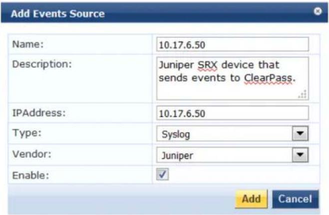
- Specify the Add Event Source parameters as described in Table 384.
Table 384: Configuring the Event Source Parameters
| Parameter Action/Description | |
| Name 1. Enter the IP address of the device that will send Syslog events to W-ClearPass. | |
| Description Optionally, enter a description of this Event Source. | |
| IP Address 2. Enter the IP address of the device that will send Syslog events to W-ClearPass. | |
| Type 3. From the drop-down, select the Event Source Type. | |
| Vendor 4. From the drop-down, select the Event Source Vendor. | |
| Enable 5. Select this check box to enable the device as an Event Source. |
- When finished, click Add.
The Event Sources page now displays the new Event Sources (see Figure 726).
Figure 726: Event Sources Page
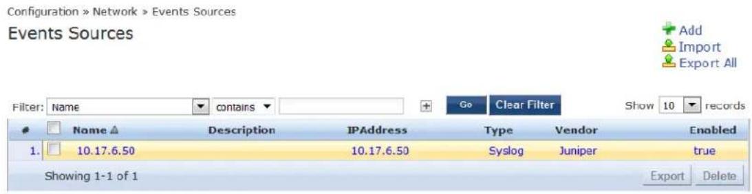
The IP address displayed in Figure 726 is the IP address and host name of the Juniper SRX gateway that sends Syslog events to W-ClearPass.
Configuring the Ingress Receiving Ports
The ingress receiving ports are the TCP (Transmission Control Protocol) and UDP (User Datagram Protocol) ports on the W-ClearPass server where the events source sends threat-related events.
By default, the ingress receiving port is 514 for both TCP and UDP. You can modify the ingress receiving ports to a custom value as necessary.
To confirm or change the ingress receiving ports on the W-ClearPass server:
-
Navigate to Administration > Server Manager > Server Configuration.
-
From the list of W-ClearPass servers, select the appropriate server.
The Server Configuration page opens.
-
Select the Service Parameters tab.
-
From the Select Service drop-down, choose Ingress syslog service as shown in Figure 727.
Figure 727: Selecting the Ingress Syslog Service
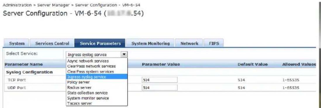
As you can see in Figure 727, the parameter value for both the TCP and UDP receiving ports is set to the default value of 514.
-
If you wish to modify the parameter values for one or both of the receiving ports, enter the new value(s).
-
When satisfied with the settings, click Save.
Configuring an Event-Based Enforcement Service
This section provides the following information:
- Introduction
- Adding an Event-Based Enforcement Service
• Associating the Enforcement Service with an Enforcement Policy
Introduction
This section describes how to add the Event-Based Enforcement service that manages enforcement actions in response to threat-event processing.
When there is a suspicious user, this user could represent a common DOS attack or some other threat. When a threat is detected, W-ClearPass performs enforcement operations as configured, for example, executing a change of authorization (COA) to disconnect a suspicious user from the network.
Adding an Event-Based Enforcement Service
To add an event-based enforcement service:
- Navigate to Configuration > Services.
The Services page opens. The Services page provides options to add, modify, and remove a service.
- To add the event-based enforcement service, click Add.
The Add Services dialog opens.
- From the Type drop-down list, select Event-based Enforcement (see Figure 728).
Figure 728: Specifying Event -Based Enforcement
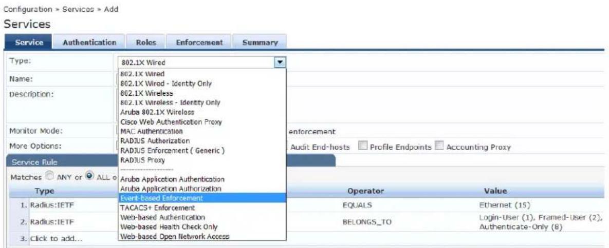
For configuration information for each of the available service types, see Configuring Policy Manager Services on page 72.
-
Enter the name or label of the event-based enforcement service.
-
Enter the values for any other parameters, including service rules, required for this service. For a description of all the parameters in the Service page, see Adding Services on page 1.
-
Click Next.
The Add Services > Enforcement tab opens.
Associating the Enforcement Service with an Enforcement Policy
After you create the event-based enforcement service, you must associate the service with an enforcement policy.
To associate an event-based enforcement server with an enforcement policy:
- When finished with the parameter settings on the Add Services > Service page, click Next. The Add Services > Enforcement page opens.
Figure 729: Specifying the Event-Based Enforcement Policy
![Configuration > Services > Add Services Enforcement policy "Event-based enforcement policy" has been added Service Enforcement Summary Use Cached Results: □ Use cached Roles and Posture attributes from previous sessions Enforcement Policy: Event-based enforcement policy Modify Enforcement Policy Details Description: Default Profile: [HPE Bounce Host-Port] Rules Evaluation Algorithm: first-applicable Conditions Enforcement Profiles 1.(Date:Day-of-Week BELONGS_TO Wednesday) [HPE Bounce Host-Port]](/content/2026/05/842116/images/3f89e0dc80ee45a08934311d380efa6f308a1352757fde3a79984e32e26d4715.jpg)
From the Add Services > Enforcement page, you can either select an existing enforcement policy or create a new one.
-
From the Enforcement Policy drop-down list, select the appropriate Event Enforcement policy.
-
If you have not configured Event-type Enforcement policies, click Add New Enforcement Policy to create a new enforcement policy.
-
Specify the values for the remaining parameters as described in Table 385, then click Save.
Table 385: Service Enforcement Page Parameters
| Parameter Action/Description | |
| Use Cached Results 1. Select this check box to use cached roles and posture attributes from previous sessions. | |
| Enforcement Policy | 2. From the drop-down list, select the preconfigured enforcement policy. This is mandatory. |
| Enforcement Policy Details | |
| Description | Displays additional information about the selected enforcement policy. |
| Default Profile | Displays a default profile applied by . |
| Rules Evaluation Algorithm | Shows first matched rule and return the role or select all matched rules and return a set of roles. |
Enabling Ingress Events Processing
The final task is to enable ingress events processing.
To enable ingress events processing on the W-ClearPass server:
-
Navigate to Administration > Server Manager > Server Configuration.
-
From the list of W-ClearPass servers, select the appropriate server.
The Server Configuration page appears.
- Select the appropriate server.
The Server Configuration dialog appears.
Figure 730: Enabling Ingress Event Processing
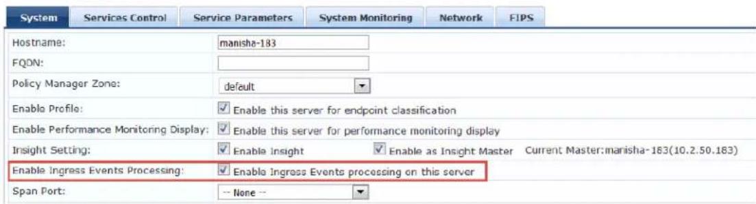
4. Click the Enable Ingress Events Processing check box.
The following warning dialog is displayed, alerting you to the impact on system performance that may when you enable ingress events processing.
Figure 731: Warning Dialog for Enabling Ingress Events Processing
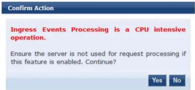
5. To proceed with ingress events processing on this server, click Yes.
For details on the Server Configuration > System Tab parameters, see System Page on page 499.
This appendix includes the following information:
- Introduction
- Accessing the OnGuard Support Charts
- Upgrading From OnGuard Plugin Version 1.0 to 2.0
• Native Agents Only Mode
• Native Agents with Java Fallback Mode - Configuring Web Agent Flow - Java Only Mode
- Native Dissolvable Agent Supported Operating Systems and Browsers
- OnGuard Dissolvable Agent Supported Browsers and Java Versions
Introduction
W-ClearPass OnGuard controls compromised devices by detecting and blocking access to unsecure or unhealthy devices. The client is denied access to network resources across wired, wireless, and remote networks when it is determined as unsecure, which is accomplished by running an extensive posture assessment.
The OnGuard Agent is supported by Windows, Linux, and Mac OS X devices.
You can configure the OnGuard Dissolvable Agent flow in different modes to perform health scans on endpoints. This section provides information on the end-to-end flow and how to configure OnGuard Dissolvable Agent in the following modes:
- Native agents only: Native Dissolvable Agent communicates with W-ClearPass Guest to send information about endpoints such as status, health status, remediation messages and so on. This communication is independent of the operating systems and browsers.
- Native agents with Java fallback: The configuration for the Native agents with Java fallback mode is similar to the Native agents only mode. The posture assessment is performed based on the user's preference.
- Java Only: The communication is dependent on the browsers and the Java Runtime Environment (JRE) versions installed. For the supported Java versions and browsers, see OnGuard Dissolvable Agent Supported Browsers and Java Versions on page 762.
Accessing the OnGuard Support Charts
For information about the OnGuard Agent Support Charts that are included with W-ClearPass Policy Manager navigate to:
Administration > Support > Documentation > OnGuard Agent Support Charts
There are two sets of support charts provided:
- OnGuard Agent Support Charts for Plugin Version 1.0 (OnGuard Detection V3 SDK)
- OnGuard Agent Support Charts for Plugin Version 2.0 (OnGuard Detection V4 SDK)

The plugin version 2.0 support charts pertain to the V4 SDK.
Figure 732: OnGuard Agent Support Charts for Plugin Versions 1.0 and 2.0
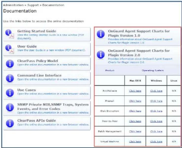
Upgrading From OnGuard Plugin Version 1.0 to 2.0
This section contains the following information:
Overview
- Creating a New Enforcement Profile to Set the SDK Type
- Modifying an Existing Enforcement Policy for OnGuard Plugin v2.0
- Creating a New Posture Policy for OnGuard Plugin v2.0 Agents
- Creating a WebAuth Service for OnGuard Plugin v2.0 Agents
- Important Points
Overview
The W-ClearPass OnGuard Agents for Windows and macOS support OnGuard plugin version 2.0, which provides faster performance, enhanced product detection, and more efficient resource allocation.
W-ClearPass supports both the 1.0 and 2.0 plugin versions by default, but because plugin version 2.0 inc significant enhancements, we recommend that you upgrade from version 1.0 to 2.0.
The new OnGuard plugin version 2.0 is based on the OESIS V4 SDK, while the earlier plugin version 1.0 is based on the OESIS V3 SDK. OnGuard continues to use plugin version 1.0 and your existing V3 SDK policies until you explicitly upgrade to plugin version 2.0, as described in this section.
To upgrade to plugin version 2.0, you will first upgrade the OnGuard agents, after which you create a n enforcement profile, enforcement policy, and a Web Auth service. Finally, you will need to modify any ex V3 SDK enforcement policies to use the V4 SDK.
Creating a New Enforcement Profile to Set the SDK Type
The first task in upgrading to the OnGuard plugin version 2.0 is to create a new enforcement profile which set the attribute SDK Type to V4.
To create the OnGuard plugin version 2.0 enforcement profile:
- Navigate to Configuration > Enforcement > Profiles.
The Enforcement Profiles page opens.
2. Click the Add link.
The Add Enforcement Profile dialog opens.
Figure 733: Adding a V4 Agent Enforcement Profile
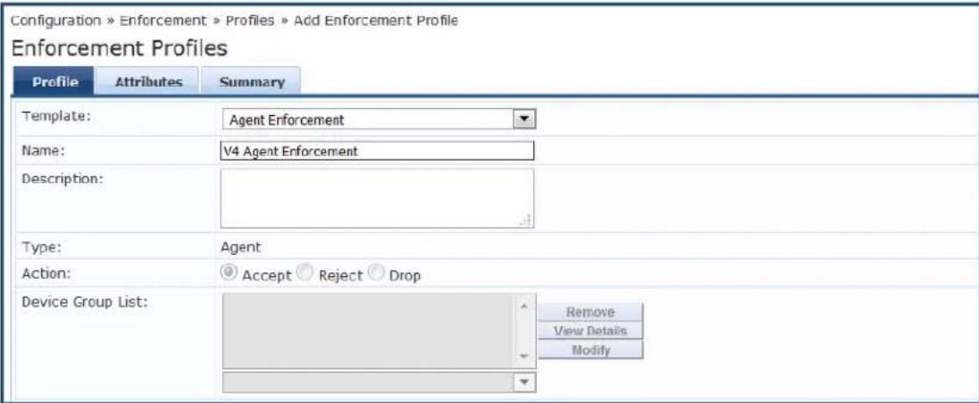
- Specify the Add V4 Agent Enforcement Profile parameters as described in the following table:
Table 386: Add V4 Agent Enforcement Profile Parameters
| Parameter Action/Description | |
| Template Select Agent Enforcement. | |
| Name Enter a name for this enforcement profile. | |
| Description Optionally (but recommended), add a description of this enforcement profile. | |
| Type | When you select the Agent Enforcement template, the enforcement profile Type is set automatically to Agent. |
| Action | Keep the default action: Accept. |
| Device Group List | The Device Group List is no longer pertinent and this option is grayed out. |
4. Click Next.
The Attributes dialog opens.
Figure 734: Specifying the SDK Type Attribute to V4
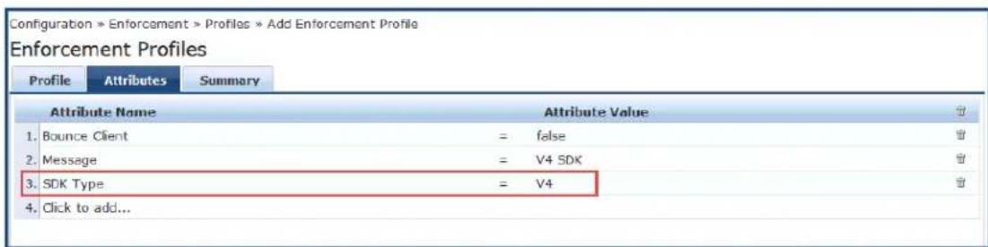
-
Optionally (but recommended), specify a message in the Message attribute.
-
Select Click to add, then make the following selections:
■ Attribute Name: SDK Type
■ Attribute Value: V4
- Click Save.
The new enforcement profile is added.
Modifying an Existing Enforcement Policy for OnGuard Plugin v2.0
If you have an existing enforcement policy of the WebAuth service that is being used for OnGuard plugin version 1.0: V3 SDK, you must modify the enforcement policy to support OnGuard plugin version 2.0.
To modify an existing enforcement policy to support OnGuard plugin version 2.0:
- Navigate to Configuration > Enforcement > Policies.
The Enforcement Policies page opens.
Figure 735: Enforcement Policies Page
![Configuration > Enforcement > Policies Enforcement Policies Filter: Name contains Go Clear Filter Show 10 records Name ▲ Type Description 1. [Admin Network Login Policy] TACACS Enforcement policy controlling access to Policy Manager Admin 2. [AirGroup Enforcement Policy] RADIUS Enforcement policy controlling access for AirGroup devices 3. [Aruba Device Access Policy] TACACS Enforcement policy controlling access to Aruba device 4. Enf WEBAUTH 5. [Guest Operator Logins] Application Enforcement policy controlling access to Guest application 6. [Insight Operator Logins] Application Enforcement policy controlling access to Insight application 7. [Sample Allow Access Policy] RADIUS Sample policy to allow network access 8. [Sample Deny Access Policy] RADIUS Sample policy to deny network access Showing 1-8 of 8 Copy Export Delete](/content/2026/05/842116/images/03ae14146fc365e1b32e459aa13d5422b294e8a2d7912d9fc9b9386836111e48.jpg)
- Select the enforcement policy of the WebAuth service that is being used for the OnGuard plugin versi 1.0.
The Edit Enforcement Policies page opens.
- Select the Enforcement tab.
Figure 736: Modifying the V3 Enforcement Policy
![Configuration » Enforcement » Policies » Edit - Enf Policy V4 Enforcement Policies - Enf Policy V4 Summary Enforcement Rules Name: Enf Policy V4 Description: Enforcement policy of the WebAuth service to be used for the V4 SDK. Enforcement Type: WEBAUTH Default Profile: [Agent] Unhealthy View Details Modify Add new Enforcement Profile](/content/2026/05/842116/images/cff2b2533327d1a25754445f34e6ce82c0f50ef500c3aba1569f43016c10da3f.jpg)
- Update the Name and Description if necessary.
- Click Modify.
- Select the Attributes tab.
Figure 737: Changing the SDK Type Attribute to V4
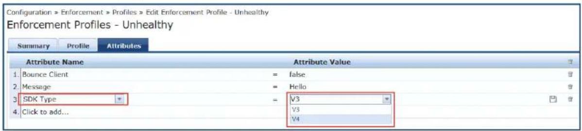
7. Change the SDK Type > Attribute Value to V4, then click Save.
The Enforcement Policy has been updated to support the OnGuard plugin version 2.0: V4 SDK. When agent next performs a health check, it picks OnGuard plugin version 2.0.
Creating a New Posture Policy for OnGuard Plugin v2.0 Agents
The supported posture policy for the OnGuard plugin version 2.0 is required because many third-party products that were not supported by OnGuard plugin version 1.0 are supported by OnGuard plugin version 2.0. Also, the names of some of the antivirus products that are recognized by the OnGuard plugin version are changed in OnGuard plugin version 2.0.
The configuration procedure for creating a posture policy for V4 SDK agents is identical to the configuration for V3 SDK agents.
When you create a new posture policy, by default the new posture policy uses V4 support charts (see Accessing the OnGuard Support Charts on page 739).
To create a posture policy for OnGuard plugin version 2.0 V4 SDK agents:
1. Navigate to Configuration > Posture > Posture Policies.
The Add Posture Policies page opens.
Figure 738: Creating a Posture Policy for OnGuard Plugin Version 2.0 V4 SDK Agents
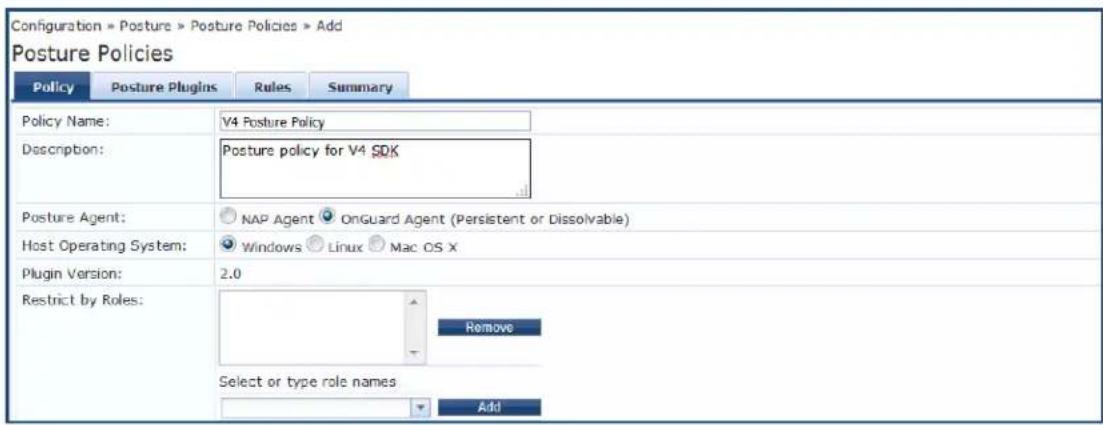
- Specify the Add V4 Posture Policy parameters as described in the following table:

Table 387: Adding V4 Posture Policy Parameters
| Parameter Action/Description | |
| Policy Name | Enter the name of this posture policy. |
| Description Optionally (but recommended), add a description of this posture policy. | |
| Posture Agent Specify OnGuard Agent (the default). | |
| Host Operating System Specify Windows (the default). | |
| Plugin Version | Plugin version 2.0 is specified by default. This is the plugin version required by the V4 SDK. |
| Restrict by Roles Configure the roles as required by your installation.For more information on role configuration, see Adding and Modifying Role page 274. | |
3. Click Next.
The Posture Plugins page opens.
Figure 739: Selecting the Posture Plugin

- Click the check box for the W-ClearPass Windows Universal System Health Validator, then click Configure:
Figure 740: Configuring the V4 Posture Plugin
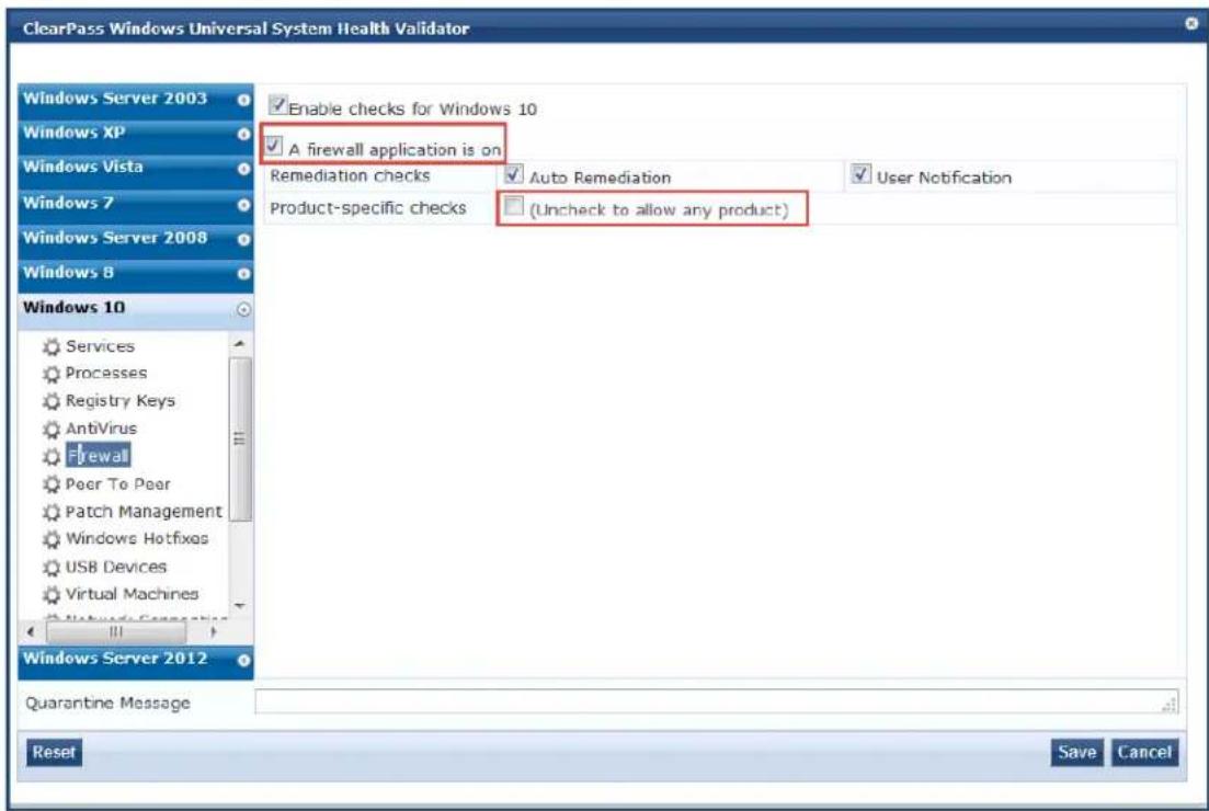
- Specify the W-ClearPass Windows Universal System Health Validator parameters as described in the following table:
Table 388: Add V4 Posture Plugin Parameters
| Parameter Action/Description | |
| Windows OS list | Select the Windows version of choice. |
| Enable checks for Windows | Select the check box for Enable checks for the selected version of Windows. |
| Firewall From the list of Windows checks, select Firewall. | |
| Firewall application | Select the check box for A firewall application is on. |
| Product-specific checks | To allow any firewall product, uncheck Product-specific checks. |
- Click Save.
Once you have defined the posture hosts, agents, and plugins, you must configure the rules for the policy.
- Select the Rules tab, then click Add Rule.
The Rules Editor opens.
Figure 741: Configuring OnGuard Plugin Version 2.0 Posture Policy Rules
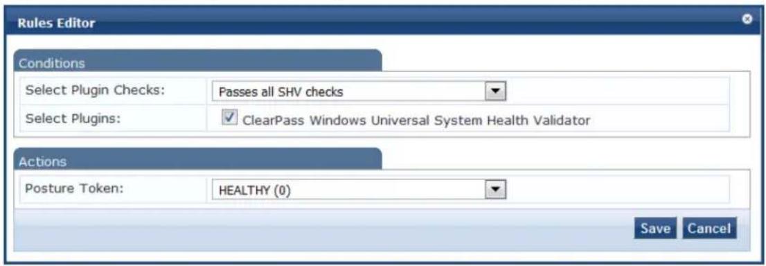
- Specify the Rules Editor parameters as described in the following table, then click Save:
Table 389: Rules Editor Parameters
| Parameter Action/Description | |
| Conditions | |
| Select Plugin Checks SelectPasses all SHV checks (the default setting).The following plugin check types are available for System Health Validators (SHVs):Passes all SHV checksPasses one or more SHV checksFails all SHV checksFails one or more SHV checks | |
| Select Plugins Select the plugin to which the plugin checks should apply.In this case, theW-ClearPass Windows Universal System Health Validator plugin has been automatically selected. | |
| Actions | |
| Posture Token | SelectHEALTHY (0) (the default setting).The following Posture Token settings are available:HEALTHY (0)CHECKUP (10)TRANSITION (15)QUARANTINE (20)INFECTED (30)UNKNOWN (100) |
The following figure displays a summary of all the settings for this posture policy:
Figure 742: Summary of V4 SDK Agents Posture Policy
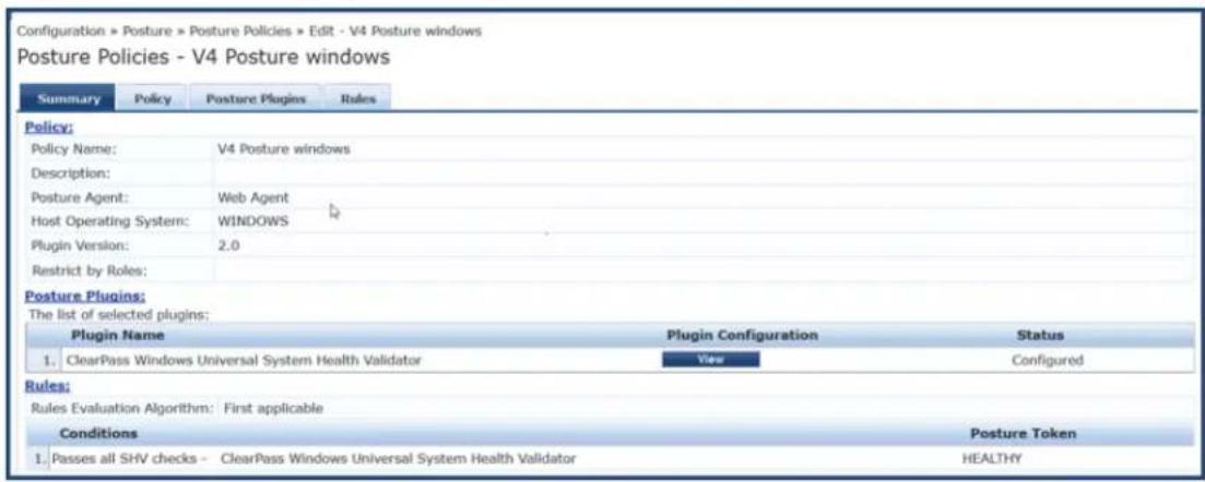
Creating a WebAuth Service for OnGuard Plugin v2.0 Agents
The final task is to create a WebAuth service for OnGuard plugin version 2.0 V4 SDK Agents. To do so:
- Navigate to Configuration > Services.
- Click Add.
The Add Services page opens.
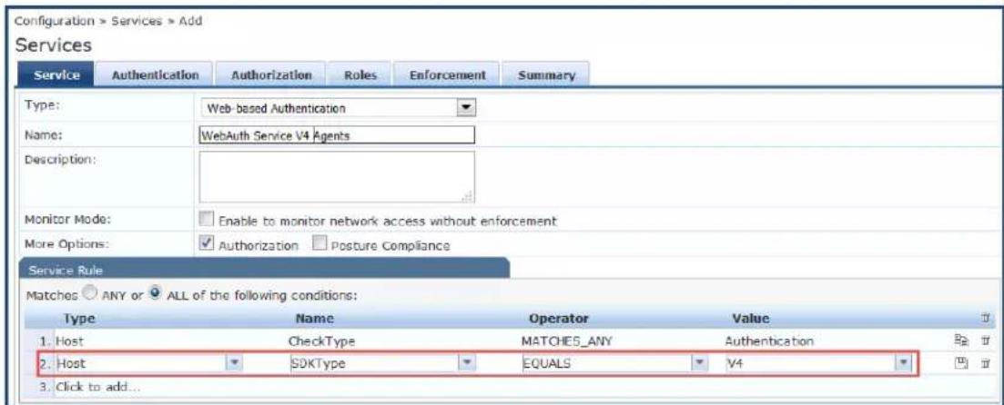
- Type: Select Web-based Authentication.
- Name: Enter the name for this service.
- Service Rule:
a. Matches: Leave the default setting, ALL of the following conditions.
b. Select Click to add... and specify the following attributes:
c. Type: Select Host.
d. Name: Select SDKType.
e. Operator: Select EQUALS.
f. Value: Select V4.
- Select the Authentication tab and specify the authentication source(s).
- Select the Enforcement tab and select the enforcement policy created in the previous section.
-
Click Save.
-
From the Services page, click Reorder, then place the service for the V4 SDK before the service for the V3 SDK.
This ensures that WebAuth requests with the V4 SDK are evaluated by the service configured for the SDK.
Important Points
- After installing W-ClearPass 6.6.7, OnGuard Agent is configured to use the OnGuard plugin version 2.0: OESIS V4 SDK by default. Thus, to fully configure the OnGuard plugin version 2.0, you must follow the procedure described above in Creating a WebAuth Service for OnGuard Plugin v2.0 Agents.
- To locate the support charts for OnGuard plugin version 2.0, navigate to Administration > Support > Documentation > OnGuard Agent Support Charts for Plugin Version 2.0.
-
The Plugin Version field in the Posture Policy > Summary tab indicates the version and related SDK as follows (see Figure 742):
-
Plugin Version 1.0: OESIS V3 SDK
-
Plugin Version 2.0: OESIS V4 SDK
-
The names of some of the third-party products (for example, AntiVirus, Firewall, and Patch Management) have changed in the OnGuard plugin version 2.0, so be sure to test the OnGuard plugin version 2.0: and Posture policies in your lab before applying them in a production environment.
- In OnGuard plugin version 2.0 Posture Policy for Windows and MacOS, AntiVirus and AntiSpyware health classes are merged into the AntiVirus health class.
- The following features/checks are not supported with the OnGuard plugin version 2.0:
■ AntiVirus health class: Engine Version Check, Display Update URL, Disable RTP Check (see AntiVirus on page 302).
- Patch Management health class: Selected On Server and Security options in the Install Level Check Type (see Patch Management on page 308).
- Note that new posture policies created on W-ClearPass Policy Manager 6.6.7 and later will be for OnG plugin version 2.0: OESIS V4 SDK.
- W-ClearPass Policy Manager 6.6.7 and later does not allow creating a new Posture Policy for OnGuard plugin version 1.0: OESIS V4 SDK. However, you can import a Posture Policy for OnGuard plugin version from the previously released versions of W-ClearPass.
- Make sure that the Agent Enforcement profile has the required SDK Type configured—V3 or V4 (see Modifying an Existing Enforcement Policy for OnGuard Plugin v2.0 on page 742).
- Make sure to use the posture policy having Plugin Version 2.0, if V4 SDK is enabled. Similarly for V3 the posture policy with Plugin Version 1.0 (see Creating a New Posture Policy for OnGuard Plugin v2.0 Agents on page 743).
- You can change the SDK Type from V4 to V3 by modifying the Agent Enforcement profile to have V3 as the SDK Type. In this case, be sure to configure the service posture policy is set to Plugin Version 1.0 (see Creating a New Enforcement Profile to Set the SDK Type on page 740).
- OnGuard Agent sends two WebAuth requests when the SDK Type is changed on a client. The first request uses the previously configured SDK Type, and the second request is for the new SDK Type.
- If an Agent Enforcement Profile without the SDK Type attribute is applied, it will not reset the SDK Type on the client; that is, once the SDK Type is changed on the client by the Agent Enforcement profile, it will not change until a new Agent Enforcement profile having a different SDK Type is applied.
-
If the Host:SDK Type attribute is missing in WebAuth Requests, it indicates that OnGuard Agent is using the V3 SDK as versions prior to OnGuard Agents version 6.6.7 do not send the Host:SDK Type attribute.
-
You can check the value of the Host::SDKType attribute in Monitoring > Access Tracker > Input > Computed Attributes.
Native Agents Only Mode
The Native Dissolvable Agent communicates with W-ClearPass Guest portal to send information about endpoints, such as status, health status, remediation messages, and so on. This communication is indepe of the operating systems and browsers.
Native Dissolvable Agent supports the following browsers and operating systems:
Table 390: Supported Operating Systems and Browsers
| OS Browsers | |
| Windows • Internet Explorer | • Firefox• Google Chrome |
| Mac OS X • Safari | • Firefox• Google Chrome |
| Linux | • FireFox |
W-ClearPass Policy Manager hosts the Native Dissolvable Agent binary files with OnGuard Persistent Agent installers.
You can use the links to download the binaries in the OnGuard Settings page for Windows (.exe) and Mac OS X (.DMG).
Navigate to: Administration > Agents and Software Updates > OnGuard Settings.
Configuring Workflow in Native Agents Only Mode
In W-ClearPass Guest, the web login page is enhanced to avoid an additional web authentication service simplifies the configuration on dissolvable agent flow with the policy-initiated login method.
To configure the OnGuard Dissolvable Agent in Native agents only mode:
- In the Login Method field, select the Policy-initiated - An enforcement policy will control a change of authorization option.
The following figure displays the policy-initiated login method in the Web Login Editor page:
Figure 743: Policy-Initiated Log-in Method
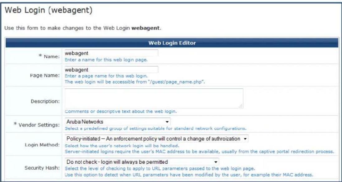
- Select the Require a successful OnGuard health check option in the Health Check field. If you select this field, the guest needs to pass a health check before accessing the network. Select the Native agents only mode in the Client Agents field:
Figure 744: Native Agents Only Mode

End-to-End Flow in Native Agents Only Mode
The following steps describe the end-to-end flow of the OnGuard Dissolvable Agent running on Native ag only mode:
-
You are redirected to the W-ClearPass Guest Portal where you can download the native agent installer
-
After accepting the terms and conditions for collecting end point posture assessment scan checks and performing remediation actions, run the Native Agent Installer.
The following figure shows an example of the Native Dissolvable Agent Login page:
Figure 745: Native Dissolvable Agent - Login Page
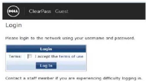

The Terms specified in the Login page are optional. You can configure this optionally by selecting the Require a Terms and Conditions confirmation check box in the Terms field in the W-ClearPass Guest Login Form.
- The figure similar to the following OnGuard Agent download prompt appears when you log in for the time to the Native Dissolvable Agent:
Figure 746: Native Dissolvable Agent Installer Prompt
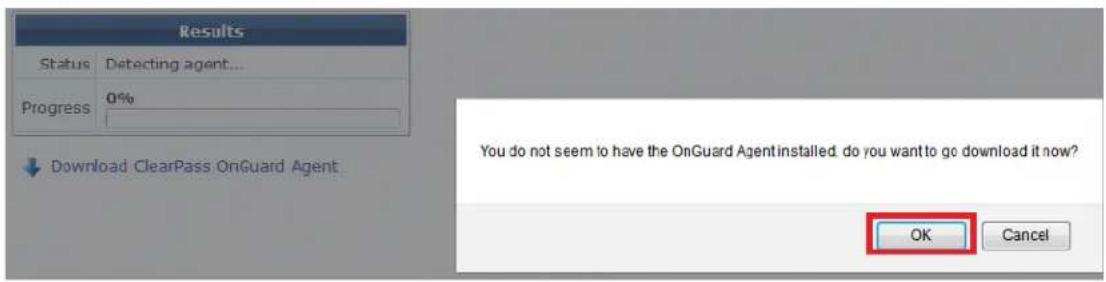
The download options are available only when you log in for the first time. Alternatively, you can download the OnGuard agent by clicking the Download W-ClearPass OnGuard Agent link.
- To download the OnGuard Agent, click OK.
The figure shows an example of the OnGuard Windows Health Checker binary download window:
Figure 747: Native Dissolvable Agent Binary Downloader
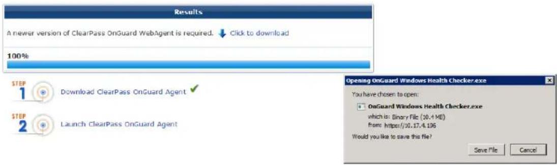
- To download the OnGuard agent, click Save File.
- To install the OnGuard agent, click Run.
Figure 748: Native Dissolvable Agent Installation
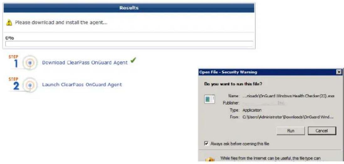

If you are running Windows OS, Internet Explorer provides options to Run or Save. Firefox and Chrome browsers provide option to save the .exe files.

If you are running Mac OS X, FireFox provides options to open the binary with DiskImageMounter or save the .DMG files.
Safari and Google Chrome browsers provide the option to Save only.
- From the Launch Application page, select the W-ClearPass OnGuard Web Agent application.
- To register and perform auto-launch of native OnGuard agent on successive log-ins, select Remember my choice for onguardwebagent links, then click OK.
Figure 749: Native Dissolvable Agent Application Launcher
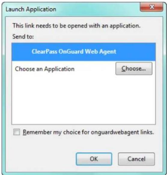
- The following progress screen appears and shows the progress:
Figure 750: Native Dissolvable Agent Installation Progress
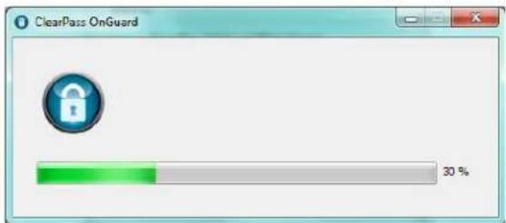
- After the successful installation, the health check scanning is initiated. The following figure shows an example of the progress indicator:
Figure 751: Health Check Progress
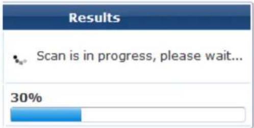
- After the health check scanning is completed, the figure similar to the following example appears with health check results if the client is unhealthy:
Figure 752: Health Check Results
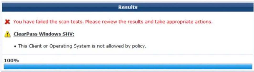
Scan Again
- Take the appropriate actions to fix the issues listed in remediation and agent enforcement messages, click Scan Again.
Repeat this step until the client becomes healthy. Once the client is healthy, you can access the desti URL.
- You can track the events with the end-to-end flow in the Access Tracker page.
The following figure shows an example of the Access Tracker page with the Native Dissolvable Agent flow:
Figure 753: Access Tracker Page
| 10. | RADIUS | suribabu | 1X-Wireless | ACCEPT | 2014/07/10 16:07:12 |
| 10. | WEBAUTH | 7cd1c373c4e4 | Health-only | ACCEPT | 2014/07/10 16:07:03 |
| 10. | RADIUS | suribabu | 1X-Wireless | ACCEPT | 2014/07/10 16:06:30 |
The Auto-launch feature works in the Native agents only and Java Only modes without user intervention to click pop-ups and options that are described in the complete end-to-end flow above, e configuring Terms in the W-ClearPass Guest Login page.
Auto-Login
The Native Dissolvable Agent supports the Auto-Login method, which eliminates the Require a Terms and Conditions confirmation check box in the Guest Web Login page by avoiding the web page and submitting automatically.
Troubleshooting
In Windows, Native Dissolvable Agent flow logs are available at:
%appdata%Aruba Networks/ ClearPassOnguard Temp/Logs
In MAC OS X, the Native dissolvable agent flow logs are available at:
\~/Library/Logs/ClearPassOnGuardTemp/logs.
Native Agents with Java Fallback Mode
This section provides the following information:
- Configuring Native Agents with Java Fallback Mode
• End-to-End Flow in Native Agents with Java Fallback Mode
The configuration steps for Native agents with or Java fallback work flow is similar to the Native agents only mode work flow. The posture assessment is performed based on your selection.
Configuring Native Agents with Java Fallback Mode
To configure the OnGuard Dissolvable Agent in Native agents with Java fallback mode:
- From the drop-down list in the Login Method field, select the Policy-initiated - An enforcement policy will control a change of authorization option.
The following figure shows an example configuration of the Policy-initiated Login method:
Figure 754: Policy-Initiated Log-in Method
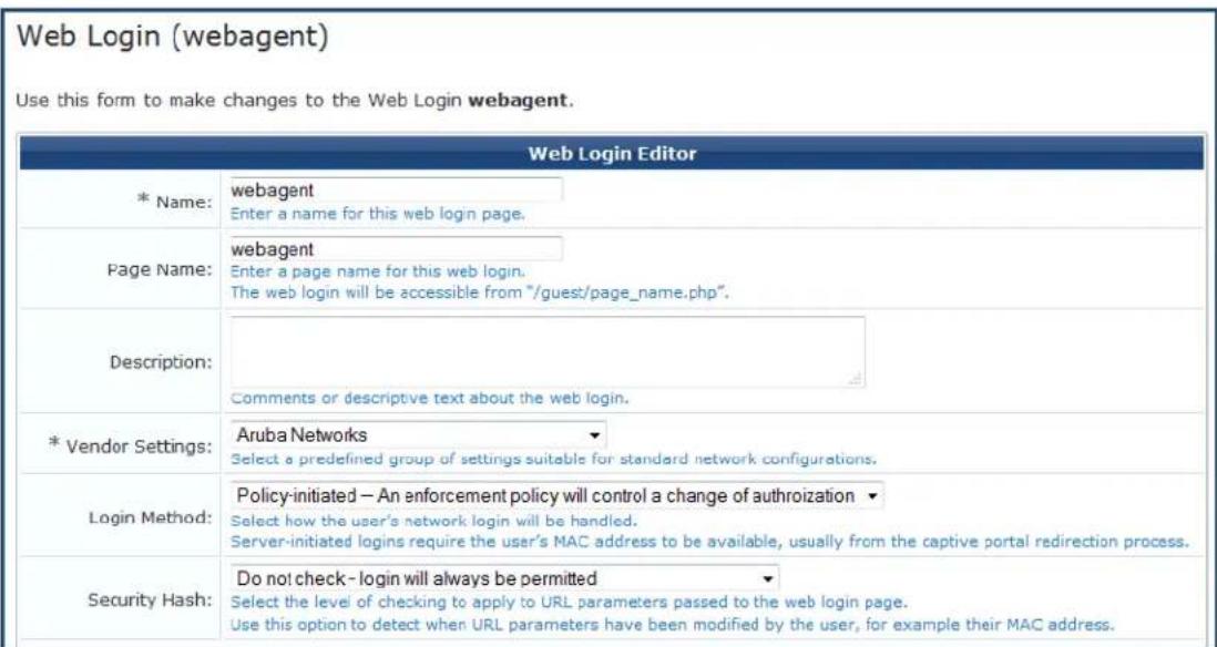
- In the Health Check field, select the Require a successful OnGuard health check option.
If you select this field, the guest needs to pass a health check before accessing the network.
- In the Client Agents field, select the Native agents with Java fallback mode:
Figure 755: Native Agents with Java Fallback Mode

End-to-End Flow in Native Agents with Java Fallback Mode
The posture assessment is performed based on your selection.
If you select Java, the Java applet is downloaded and posture assessment is performed. The native agent provided in Java launcher to avoid the JRE files loaded into the system.
The following figure shows an example of the Native agents with Java fallback options:
Figure 756: Native Dissolvable Agents with Java Fallback
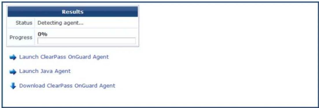
Configuring Web Agent Flow - Java Only Mode
You can configure a new web agent flow in two different locations (W-ClearPass Policy Manager and W-ClearPass Guest) to perform health scan on endpoints.
Configuring Web Agent Flow in W-ClearPass Policy Manager
Use the following steps to configure a new web agent flow in W-ClearPass Policy Manager:
- Create a 802.1X service to perform RADIUS authentication and enforce restricted or full access based end point posture assessments. The following figure shows an example of the Web Agent Flow - 802.1X Service page:
Figure 757: Web Agent Flow - 802.1X Service
Configuration » Services » Edit - 1X-Wireless
Services - 1X-Wireless
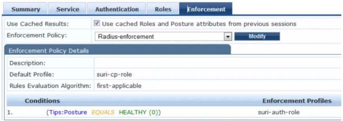
- Create a service named Web-based Health Check Only on the W-ClearPass Policy Manager server. The following figure shows an example of the Web Agent Flow - Health Only page:
Figure 758: Web Agent Flow - Health Only
Configuration » Services » Edit - Health-Only
Services - Health-Only
![Summary Service Roles Posture Enforcement Use Cached Results: Use cached Roles and Posture attributes from previous sessions Enforcement Policy: Web-CoA-enforcement Modify Add new Enforcement Enforcement Policy Details Description: Default Profile: Web-CoA-init Rules Evaluation Algorithm: first-applicable Conditions 1. (Tips:Posture EQUALS HEALTHY (0)) 2. (Tips:Posture NOT_EQUALS HEALTHY (0)) Enforcement Profiles [Aruba Terminate Session], Entity-updatelasthealthstate Entity-updatelasthealthstate](/content/2026/05/842116/images/eca70e6fd3d8c1edf6171ca71b014bec66fd0c085b16d12b10a2919abd935190.jpg)
- Create a simple Web Auth service to authenticate users against W-ClearPass Guest user database to a or perform App authentication request after completing a sandwich flow. The following figure shows a example of the Web Agent Flow - Services Web Auth page:
Figure 759: Web Agent Flow - Services Web Auth
![Configuration » Services » Edit - Web-auth Services - Web-auth Summary Service Authentication Roles Posture Enforcement Authentication Sources: [Guest User Repository] [Local SQL DB] AD-Pegasus [Active Directory] [Local User Repository] [Local SQL DB] --Select to Add-- Move Up Move Down Remove View Details Modify Add Strip Username Rules: Enable to specify a comma-separated list of rules to strip username prefixes or suffixes](/content/2026/05/842116/images/ed4a18bee293b5e666e3efe53cba5f78cfa905f3e7e13370fc93b4e82891512e.jpg)
Configuring Web Agent Flow in W-ClearPass Guest
Use the following steps to create a web agent flow in W-ClearPass Guest:
- Click Create a new web login page on the right corner of the W-ClearPass Guest UI. The following figure shows an example of the Web Login Editor page:
Figure 760: Web Login Editor
Web Login (new)
Use this form to create a new Web Login.
| Web Login Editor | |
| * Name: | Webagent Enter a name for this web login page. |
| Page Name: | Webagent Enter a page name for this web login. The web login will be accessible from "/guest/page_name.php". |
| Description: | Comments or descriptive text about the web login. |
| * Vendor Settings: | Aruba Networks Select a predefined group of settings suitable for standard network configurations. |
| Login Method: | Server-initiated — Change of authorization (RFC 3576) sent to controller Select how the user's network login will be handled. Server-initiated logins require the user's MAC address to be available, usually from the captive portal redirection process. |
| Security Hash: | Do not check – login will always be permitted Select the level of checking to apply to URL parameters passed to the web login page. Use this option to detect when URL parameters have been modified by the user, for example their MAC address. |
- Select the Anonymous - Do not require a username or password option from the drop-down.
- Check the Enable bypassing the Apple Captive Network Assistant option in the Prevent CNA field.
- Select the Local - match a local account option in the Pre-Auth Check field.
- Check the Require Terms and Conditions confirmation option in the Terms field.
- Specify the destination URL to which the client must be redirected after health checks in the Default destination field.
Figure 761: Web Login - Login Form
| Login Form Options for specifying the behaviour and content of the login form. | |
| Authentication: | Anonymous - Do not require a username or password Select the authentication requirement. Access Code requires a single code (username) to be entered. Anonymous allows a blank form requiring just the terms or a Log In button. A pre-existing account is required. Access Code and Anonymous require the account to have the Username Authentication field set. |
| Auto-Generate: | □ Auto-generate the anonymous account The account will be created without a session limit or expiration time, and with the Guest role (ID 2). |
| * Anonymous User: | The account to use for anonymous authentication. The password will be visible within the HTML. It is recommended to increase the account Session Limit to the number of guests you wish to support. |
| Prevent CNA: | ✓ Enable bypassing the Apple Captive Network Assistant The Apple Captive Network Assistant (CNA) is the pop-up browser shown when joining a network that has a captive portal. Note that this option may not work with all vendors, depending on how the captive portal is implemented. |
| Custom Form: | □ Provide a custom login form If selected, you must supply your own HTML login form in the Header or Footer HTML areas. |
| Custom Labels: | □ Override the default labels and error messages If selected, you will be able to alter labels and error messages for the current login form. |
| * Pre-Auth Check: | Local - match a local account Select how the username and password should be checked before proceeding to the NAS authentication. |
| Terms: | ✓ Require a Terms and Conditions confirmation If checked, the user will be forced to accept a Terms and Conditions checkbox. |
| Default Destination Options for controlling the destination clients will redirect to after login. | |
| * Default URL: | http://example.com Enter the default URL to redirect clients. Please ensure you prepend "http://" for any external domain. |
| Override Destination: | □ Force default destination for all clients If selected, the client's default destination will be overridden regardless of its value. |
- Select the Local - match a local account option in the Post Authentication field. The following figure shows an example of the Web Login - Post-Authentication page:
Figure 762: Web Login - Post-Authentication

The following figure shows an example of the final web agent flow:
| 10.17.4.197 | RADIUS | Suribabu | 1X-Wireless | ACCEPT | 2014/03/07 16:36:07 |
| 10.17.4.197 | WEBAUTH | 21886813 | Web-auth | ACCEPT 2014/03/07 16:35:59 | |
| 10.17.4.197 | WEBAUTH | f0b47912ab19 | Health-Only | ACCEPT | 2014/03/07 16:35:58 |
| 10.17.4.197 | RADIUS | suribabu | 1X-Wireless | ACCEPT | 2014/03/07 16:35:46 |
For more information, refer to W-ClearPass Guest Online Help.
Native Dissolvable Agent Supported Operating Systems and Browsers
This section provides information on the supported operating systems and browsers for the Native Disso Agent. The versions given in the following table are tested and are up-to-date at the time of this release
Table 391: Native Dissolvable Agent Supported Browsers and Java Versions
| Operating System | Browser Test | Results Known Issues Tested Versions | ||
| Windows Operating System Support | ||||
| Windows 10 64-bit | Chrome | Passed W-ClearPass Policy | Manager6.6.0.79875, Chrome 48.X | |
| Firefox Passed | W-ClearPass Policy Manager | 6.6.0.79875, Firefox 44.X | ||
| Internet Explorer | Passed W-ClearPass Policy Manager | 6.6.0.79875, IE-11.X | ||
| Windows 10 32-bit | Chrome | Passed | Health data collection does not work in a 64-bit JRE/browser | W-ClearPass Policy Manager6.6.0.79875, Chrome 48.X |
| Firefox | Passed | W-ClearPass Policy Manager6.6.0.79875, Firefox 44.X | ||
| Internet Explore | Passed W-ClearPass Policy Manager | 6.6.0.79875, IE-8.X | ||
| Windows 8.1 64-bit | Chrome | Passed W-ClearPass Policy Manager | 6.6.0.79875, Chrome 49.X | |
| Firefox Passed | W-ClearPass Policy Manager | 6.6.0.79875, Firefox 44.X | ||
| Internet Explorer | Passed W-ClearPass Policy Manager | 6.6.0.79875, IE-11.x | ||
| Windows 7 64-bit | Chrome | Passed | W-ClearPass Policy Manager6.6.0.79875, Chrome 48.X | |
| Firefox | Passed | None | W-ClearPass Policy Manager6.6.0.79875, Firefox 44.X | |
| IE | Passed | None | W-ClearPass Policy Manager6.6.0.79875, IE-11.x | |
| Windows 8 64-bit | Chrome | Passed W-ClearPass Policy Manager | 6.6.0.79875, Chrome 48.X | |
| Firefox Passed | W-ClearPass Policy Manager | |||
| Operating System | Browser Test | Results Known | Issues Tested Versions | |
| 6.6.0.79875 , Firefox 44.X | ||||
| Internet Explorer | Passed W-ClearPass | Policy Manager | 6.6.0.79875 , IE-10.X | |
| Windows 8 32-bit | Chrome Passed | W-ClearPass Policy | Manager | 6.6.0.79875 , Chrome 48.X |
| Firefox Passed | W-ClearPass Policy Manager | 6.6.0.79875 , Firefox 44.X | ||
| Internet Explorer | Passed W-ClearPass Policy Manager | 6.6.0.79875 , IE-10.X | ||
| Windows 2008 64-bit | Chrome Passed | W-ClearPass Policy | Manager | 6.6.0.79875, Chrome 41.X |
| Firefox Passed | None | W-ClearPass Policy Manager6.6.0.79875, Firefox 44.X | ||
| IE 8.X 32-bit | Passed W-ClearPass Policy Manager | 6.6.0.79875 , IE-8.x | ||
| Windows XP SP3 | Chrome Not supported | None | W-ClearPass Policy Manager6.6.0.79875, Chrome 34.X | |
| Firefox Not supported | None | W-ClearPass Policy Manager6.6.0.79875, Firefox 30.X | ||
| IE 8.X 32-bit | Not supported | W-ClearPass Policy Manager6.6.0.79875, IE-8.x | ||
| Windows 2003 32-bit | Chrome Not supported | W-ClearPass Policy Manager6.6.0.79875, Chrome 35.X | ||
| Firefox Not supported | W-ClearPass Policy Manager6.6.0.79875, Firefox 30.X | |||
| IE | Not supported | W-ClearPass Policy Manager6.6.0.79875, IE-8.x | ||
| Windows Vista | Chrome Passed | W-ClearPass Policy | Manager | 6.6.0.79875, Chrome 48.X |
| Firefox Passed | None | W-ClearPass Policy Manager6.6.0.79875, Firefox 44.X | ||
| IE 7.X 32-bit | Passed | None | W-ClearPass Policy Manager6.6.0.79875, IE-7.X | |
| Mac OS X Support | ||||
| Mac OS X 10.11 | Safari 9.x Passed | W-ClearPass Policy | Manager | 6.6.0.79875, Safari 9.X |
| Firefox 44.x Passed | W-ClearPass Policy Manager | 6.6.0.79875, Firefox 44.X | ||
| Chrome 48.x Passed | W-ClearPass Policy Manager | 6.6.0.79875, Chrome-48.x | ||
| Mac OS X 10.10 | Safari 9.x Passed | W-ClearPass Policy Manager | 6.6.0.79875, Safari 9.X | |
| Firefox 44.x Passed | W-ClearPass Policy Manager | 6.6.0.79875, Firefox 44.X | ||
| Chrome 48.x Passed | W-ClearPass Policy Manager | 6.6.0.79875, Chrome-48.x | ||
| Mac OS X 10.9 | Safari Passed | W-ClearPass Policy Manager | 6.6.0.79875, Safari 7 | |
| Firefox Passed | W-ClearPass Policy Manager | 6.6.0.79875, Firefox 44 | ||
| Chrome Passed | W-ClearPass Policy Manager | 6.6.0.79875, Chrome-48. | ||
| Mac OS X 10.8 | Safari Passed | W-ClearPass Policy | Manager6.6.0.79875, Safari-6.x | |
| Firefox Passed | W-ClearPass Policy Manager | 6.6.0.79875, Firefox-43.x | ||
| Chrome Passed | W-ClearPass Policy Manager | 6.6.0.79875, Chrome-47.x | ||
| Mac OS X 10.7.5 | Safari Passed | W-ClearPass Policy | Manager6.6.0.79875, Safari-6.x | |
| Firefox Passed | W-ClearPass Policy Manager | 6.6.0.79875, Firefox-44.x | ||
| Chrome Passed | W-ClearPass Policy Manager | 6.6.0.79875, Chrome-48.x | ||
| Mac OS X 10.11 | Safari Passed | W-ClearPass Policy Manager | 6.6.0.79875, Safari 9.X | |
| Operating System | Browser Test | Results Known Issues Tested Versions | ||
| Firefox Passed | W-ClearPass Policy Manager | 6.6.0.79875, Firefox 44.X | ||
| Chrome Passed | W-ClearPass Policy Manager | 6.6.0.79875, Chrome-48.X | ||
| Unbuntu Operating System Support | ||||
| Ubuntu12.04 32-bit LTS | Firefox Passed | W-ClearPass Policy | Manager6.6.0.79875, Firefox-38.x | |
| Chrome No support | W-ClearPass Policy Manager6.6.0.79875, Chrome 39.X | |||
| Ubuntu12.04 64-bit LTS | Firefox Passed | None | W-ClearPass Policy Manager6.6.0.79875, Firefox-34.x | |
| Chrome No support | W-ClearPass Policy Manager6.6.0.79875, Chrome 39.X | |||
| Ubuntu14.04 32-bit LTS | Firefox Passed | None | W-ClearPass Policy Manager6.6.0.79875, Firefox-38.x | |
| Chromium | Failed | W-ClearPass Policy Manager6.6.0.79875, Chrome 39.X | ||
| Ubuntu14.04 64-bit LTS | Firefox Passed | None | W-ClearPass Policy Manager6.6.0.79875, Firefox-44.X | |
| Chromium | Failed | W-ClearPass Policy Manager6.6.0.79875, Chrome 39.X1 and Chromium 39.X | ||
For more information on known issues, refer to the W-ClearPass Policy Manager 6.6 Release Notes.
OnGuard Dissolvable Agent Supported Browsers and Java Versions
This section provides information on supported browsers and Java versions for the OnGuard Dissolvable Agent. The versions given in the following table are tested and are up-to-date at the time of this release
Table 392: OnGuard Dissolvable Agent Supported Browsers and Java Versions
| Operating System | Browser | Java Version | Test Results | Known Issues | Tested Versions |
| Windows 10 64-bit | Chrome 8u73 | Failed Health data | collection does not work in a 64-bit JRE/ browser | W-ClearPass Policy Manager 6.6.0.79875, Chrome 41.X | |
| Firefox 44.x | 8u73 Passed W-ClearPass Policy | Manager 6.6.0.79875, Firefox 44.X | |||
| Internet Explorer 11.x | 8u73 Passed W-ClearPass Policy | Manager 6.6.0.79875, IE-11.x | |||
| Windows 10 32-bit | Chrome 8u73 | Failed | Health data collection does not work in a 64-bit JRE/ browser | W-ClearPass Policy Manager 6.6.0.79875, Chrome 414 | |
| Firefox 44.x | 8u73 Passed W-ClearPass Policy | Manager 6.6.0.79875, Firefox 44.X | |||
| Internet Explorer 11.x | 8u73 Passed W-ClearPass Policy | Manager 6.6.0.79875, IE11.x | |||
| Windows 7 64-bit | Chrome 8u73 | Failed | Health data collection does not work in a 64-bit JRE/ browser | W-ClearPass Policy Manager 6.6.0.79875, Chrome 48.X | |
| Firefox 8u73 | Passed | W-ClearPass Policy Manager 6.6.0.79875, Firefox 44.X | |||
| IE 8u73 Passed | W-ClearPass Policy Manager6.6.0.79875, IE-11.X | ||||
| Windows 7 32-bit | Chrome 8u73 | Failed | W-ClearPass Policy Manager 6.6.0.79875, Chrome 44.X | ||
| Firefox 8u73 | Passed | W-ClearPass Policy Manager 6.6.0.79875, Firefox 44.X | |||
| IE 8u73 | Passed | W-ClearPass Policy Manager 6.6.0.79875, IE-11.X | |||
| Windows 8 64-bit | Chrome 8u73 | Failed Health data | collection does not work in a 64-bit JRE/browser | W-ClearPass Policy Manager 6.6.0.79875, Chrome 48.X | |
| Firefox 8u73 | Passed W-ClearPass Policy | Manager 6.6.0.79875, Firefox 44.X | |||
| IE 32-bit 8u73 | Passed W-ClearPass Policy | Manager 6.6.0.79875, IE-10.X | |||
| Windows 8 32-bit | Chrome 8u73 | Failed | W-ClearPass Policy | Manager 6.6.0.79875, Chrome 48.X | |
| Firefox 8u73 | Passed W-ClearPass Policy | Manager 6.6.0.79875, Firefox 44.X | |||
| IE 8u73 | Passed W-ClearPass Policy | Manager 6.6.0.79875, IE-10.X | |||
| Windows 8.1 64-bit | Chrome 8u73 | Failed | W-ClearPass Policy | Manager 6.6.0.79875, Chrome 44.X | |
| Firefox 8u73 | Passed W-ClearPass Policy | Manager 6.6.0.79875, Firefox 40.X | |||
| IE 8u73 | Passed W-ClearPass Policy | Manager 6.6.0.79875, IE-11.X | |||
| Windows 8.1 32-bit | Chrome 8u73Firefox 8u73 | FailedPassed W-ClearPass Policy | W-ClearPass Policy | Manager 6.6.0.80940, Chrome 49.XManager 6.6.0.80940, Firefox 45.X | |
| IE 8u73 Passed W-ClearPass | Policy | Manager 6.6.0.80940, IE-11.x | |||
| Windows 2008 64-bit | Chrome 8u73 | Failed | Health data collection does not work in a 64-bit JRE/browser | W-ClearPass Policy Manager 6.6.0.79875, Chrome 41.X | |
| Firefox 8u73 | Passed | W-ClearPass Policy Manager 6.6.0.79875, Firefox 44.X | |||
| IE 8u73 Passed W-ClearPass | Policy | Manager6.6.0.79875, IE-7.x | |||
| Windows Vista | Chrome 8u73 | Failed Health data | collection does not work in a 64-bit JRE/browser | W-ClearPass Policy Manager 6.6.0.79875, Chrome 48.X | |
| Firefox 8u73 | Passed W-ClearPass Policy | Manager 6.6.0.79875, Firefox 44.X | |||
| IE 8u73 W-ClearPass Policy | Manager 6.6.0.79875, IE-9.X | ||||
| Windows 2003 32-bit | Chrome 8u73 | Not supported | W-ClearPass Policy | Manager 6.6.0.79875, Chrome 35.X | |
| Firefox 8u73 | Not supported | W-ClearPass Policy | Manager 6.6.0.79875, Firefox 30.X | ||
| IE 8u73 Not | supported W-ClearPass Policy | Manager 6.6.0.79875, IE 8.X | |||
| Windows XP 32-bit | Chrome 8u73 | Not supported | W-ClearPass Policy | Manager 6.6.0.79875,Chrome 35.X | |
| Firefox 8u73 | Not supported | W-ClearPass Policy | Manager 6.6.0.79875, Firefox 30.X | ||
| IE 8u73 Not | supported W-ClearPass Policy | Manager 6.6.0.79875, IE-8.x | |||
| Mac 10.11 | Safari 8u73 | Passed Java plug-in | must be enabled to "Run in Unsafe Mode" | W-ClearPass Policy Manager 6.6.0.79875, Safari 9.X | |
| Firefox 8u73 | Passed W-ClearPass Policy | Manager 6.6.0.79875, Firefox 44.X | |||
| Chrome | 8u73 Failed | W-ClearPass Policy Manager 6.6.0.79875, Chrome-44.x | |||
| Mac 10.10 | Safari 8u73 | Passed Java plug-in | must be enabled to "Run in Unsafe Mode" | W-ClearPass Policy Manager 6.6.0.79875, Safari 9.X | |
| Firefox 8u73 | Passed W-ClearPass Policy | Manager 6.6.0.79875, Firefox 44.X | |||
| Chrome | 8u73 Failed | W-ClearPass Policy Manager 6.6.0.79875, Chrome-44.x | |||
| Mac 10.9.5 | Safari 8u73 | Passed Java plug-in | must be enabled to "Run in Unsafe Mode" | W-ClearPass Policy Manager 6.6.0.79875, Safari 7.X | |
| Firefox 8u73 | Passed W-ClearPass Policy | Manager 6.6.0.79875, Firefox 44.X | |||
| Chrome 8u73 | Failed W-ClearPass Policy | Manager 6.6.0.79875, Chrome-44.x | |||
| Mac 10.8 Safari | 8u73 Passed | Java plug-in | must be enabled to "Run in Unsafe Mode" | W-ClearPass Policy Manager6.6.0.79875, Safari 6.X | |
| Firefox 8u73 | Passed W-ClearPass Policy | Manager 6.6.0.79875, Firefox 44.X | |||
| Chrome | 8u73 | Failed W-ClearPass Policy | Manager 6.6.0.79875, Chrome-44.x | ||
| Unbuntu Firefox | 8u73 Passed | W-ClearPass Policy | Manager 6.6.0.79875, Firefox 44.X | ||
| Fedora Firefox | 8u73 Failed W-ClearPass Policy | Manager 6.6.0.79875, Firefox 44.X | |||
| CentOS Firefox | 8u73 Passed | W-ClearPass Policy | Manager 6.6.0.79875, Firefox 44.X | ||
| RedHat | Firefox 8u73 | Passed W-ClearPass Policy | Manager 6.6.0.7987, Firefox 44.X | ||
| Suse | Firefox 8u73 | Passed W-ClearPass Policy | Manager 6.6.0.7987, Firefox 44.X | ||
For more information on Known Issues, refer to W-ClearPass Policy Manager 6.6 Release Notes.
This chapter describes how to use the W-ClearPass 6.6 Insight Reporting tool.
This chapter includes the following information:
• About W-ClearPass Insight
• About the Insight Dashboard
• Searching the Insight Database
- Creating Alerts
- Creating Reports
• Insight Report Categories Reference
• Administration Operations
• Managing Insight Admin Privileges
About W-ClearPass Insight
This section presents an overview of W-ClearPass Insight. It provides the following information:
- Introduction
- Enabling Insight and Specifying a Master Insight Node
- Launching Insight
Introduction
W-ClearPass Insight is an application for use with W-ClearPass Policy Manager that is capable of aggregat data from multiple Policy Manager appliances that contain archived network access logs.
You can access each application within the W-ClearPass suite with a single login. You need only sign in access to W-ClearPass Policy Manager, Insight, Onboard, and Guest. For more information, see Launching Insight below.
- Insight makes it easy to add many different types of report "widgets" that will produce reports that provide the specific kinds of information you need to monitor and understand what is occurring on the network. You can create customized reports to track detailed authentication records, audit trails, and details on network-access trends (see About the Insight Dashboard on page 772).
- The Insight Search feature allows you to search for clients, users, W-ClearPass servers, and network access devices (see Searching the Insight Database on page 781).
- This chapter illustrates how to generate customized reports that analyze authentication information, device profiling, client health and posture data, as well as guest and BYOD use cases (for details, see Creating Reports on page 789 and Insight Report Categories Reference on page 798).
- This chapter also describes how to configure alerts that allow you to receive near-real-time messages regarding anomalous network activity. Alerts can be delivered via SMS or email notification to multiple recipients.
You can also set up a User Watchlist (a list of VIPs, executives or devices that warrant special tracking you can monitor for authentication failures or other key events (see Creating Alerts on page 783).
- Finally, this chapter provides information on how to configure operational elements about file transfers, as well as database and report data retention (see Administration Operations on page 813).
Browsers Supported
W-ClearPass Insight uses a Web-based management interface. The following browsers are supported:
• Apple Safari 6.2.x, 7.1.x, 8.0
• Google Chrome 47.x, 48.x
• Microsoft Edge 25.x
• Microsoft Internet Explorer 11.0
- Mozilla Firefox 43, 44
Enabling Insight and Specifying a Master Insight Node
Before you can use Insight, you must enable it on the current W-ClearPass server.
If multiple nodes in a cluster have Insight enabled, one node should be configured as an Insight Master.
Insight Reports, Alerts, and Administration settings can be configured on a Master Insight node only. To be able to generate a report, enabling the node as an Insight Master (even in a single-node cluster) is mandatory.
To enable Insight :
- Navigate to Administration > Server Manager > Server Configuration.
- From the list of W-ClearPass servers, click the server on which you want to enable Insight.
The Server Configuration > System page opens.
Figure 763: Server Configuration > System Page
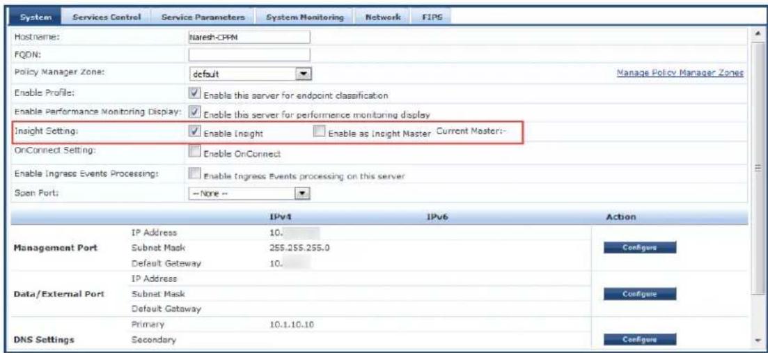
a. Enable Insight: Select this check box to enable W-ClearPass Insight on the current server.
b. Enable as Insight Master: Select this check box to specify this server as an Insight Master.
To enable replication of Insight configurations across a cluster, you must configure one W-ClearPass server in the cluster as an Insight Master node.
3. Click Save.


Launching Insight
To launch W-ClearPass Insight:
-
Use one of the following methods to launch W-ClearPass Insight.
-
Log in to Policy Manager, and then select Insight in the Dashboard > Applications widget. This opens Insight in a new tab.
- Access Policy Manager by pointing the browser to https://
/tips, then select the ClearPass Insight link (see Figure 764). -
Point the browser to https://
/insight. -
Enter the default username and password, then click Login to launch Insight.
Figure 764 displays the W-ClearPass Access page:
Figure 764: W-ClearPass Access Page
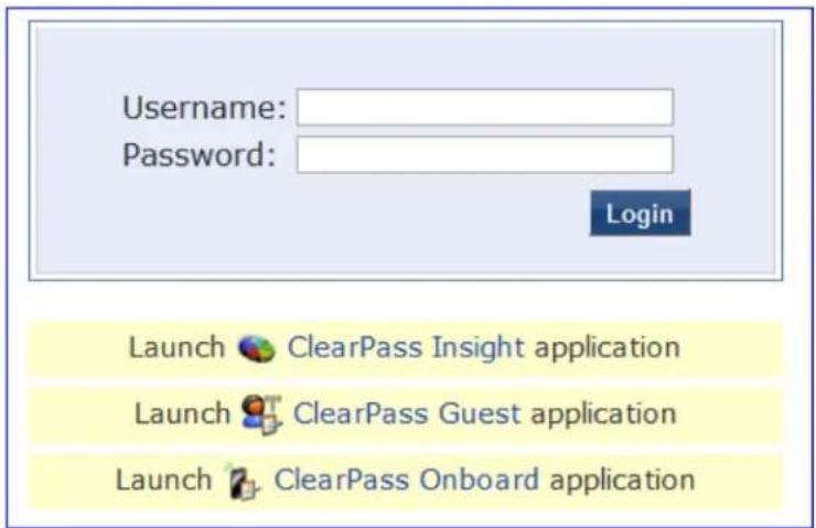
About the Insight Dashboard
This section provides the following information:
- Dashboard Overview
- Adding a Report Widget to the Dashboard Landing Page
- Removing a Report Widget from the Dashboard Landing Page
- Creating a Report or Alert From the Dashboard
- Specifying the Date Range for Data Collection
• Authentication Dashboard
• Endpoints Dashboard - Guest Dashboard
• Network Dashboard
• Posture Dashboard - System Dashboard
• System Monitor Dashboard
Dashboard Overview
The Dashboard Landing Page opens immediately when you successfully log in to W-ClearPass Insight. The Dashboard includes report widgets that provide a summarized and graphical view of your network analyt
- You can customize the Dashboard to display the report widgets that you use most often by adding widgets to the Dashboard Landing Page; you can also remove any report widget from the Dashboard Landing as needed.
- You can create reports and alerts from any of the Dashboard pages.
Figure 765: Insight Dashboard Landing Page
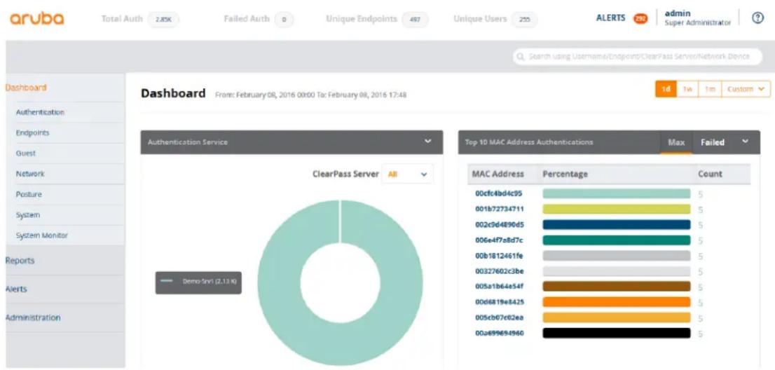
pie
| MAC Address | Percentage | Count | | --- | --- | --- | | 00cfc4bd4c95 | 5 | 5 | | 001b72734711 | 5 | 5 | | 002c9d4890d5 | 5 | 5 | | 006e4f7a8d7c | 5 | 5 | | 00b1812461fe | 5 | 5 | | 00327602c3be | 5 | 5 | | 005a1b64e54f | 5 | 5 | | 00d6819e8425 | 5 | 5 | | 005cb07e62ea | 5 | 5 | | 00a699684960 | 5 | 5 |The following report widgets are included by default on the Dashboard Landing page:
• Authentication Trend
• Authentication Distribution
• Authentication Service
• Top 10 MAC Address Authentications
Adding a Report Widget to the Dashboard Landing Page
When you add a report widget to the Dashboard Landing page, that widget will appear in the Landing page and the widget will also continue to be available on its Dashboard category page (for example, if you add Top 10 Restarted Services widget from the System Dashboard, the Top 10 Restarted Services widget would be present in both the Dashboard Landing page and the System Dashboard).
To add a report widget to the Dashboard Landing page:
-
From any of the Dashboard category pages, click the arrow icon in the right corner of the widget title
-
Select Add to Dashboard (see Figure 766).
That report widget will appear when you return to the Dashboard Landing page.
Figure 766: Adding a Widget to the Dashboard Landing Page
Network Dashboard From: 2016-01-26 00:00 To: 23:55

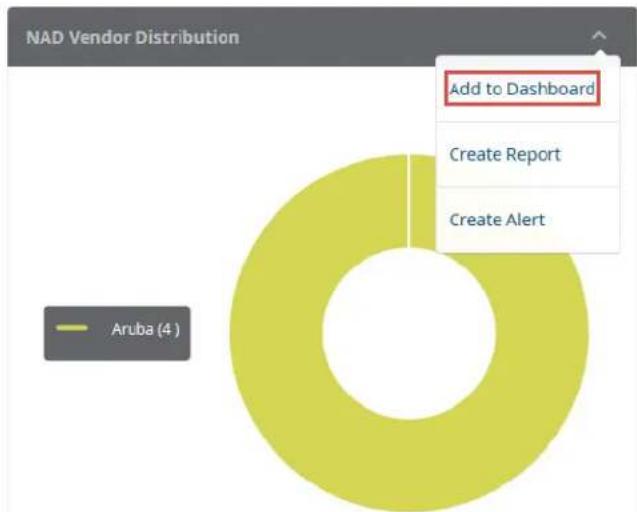
pie
| Category | Value | | ------------------ | ----- | | Add to Dashboard | 100% | | Create Report | 5% | | Create Alert | 5% |- To view the newly-added widget, return to the Dashboard Landing page.
Removing a Report Widget from the Dashboard Landing Page
You can only remove a report widget from the Dashboard Landing Page. Report widgets cannot be deleted from Dashboard category pages (for example, if you choose to remove the Top 10 MAC Address Authentications widget from the Landing page, it will remain in the set of report widgets provided in the Authentication Dashboard).
To remove a report widget from the Dashboard Landing page:
-
From the Dashboard Landing Page, locate the widget you want to remove.
-
Click the arrow icon in the right corner of the widget title bar.
-
From the menu, select Remove from Dashboard (see Figure 767).
Figure 767: Removing a Widget From the Dashboard
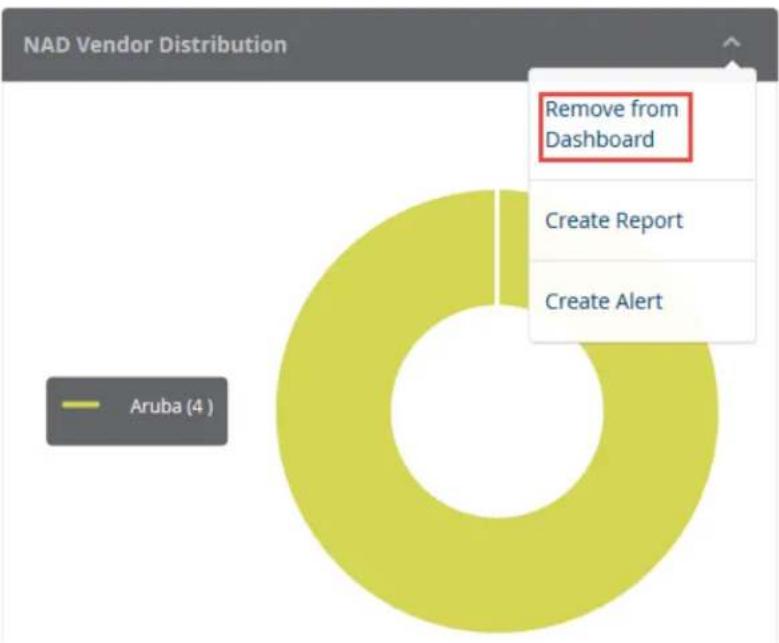
pie
| Category | Value | | -------------------- | ----- | | Aruba | 4 |When you refresh the page, that widget will disappear from the Dashboard.
Creating a Report or Alert From the Dashboard
The widgets on the Dashboard include links to the Creat Reports and Create Alerts pages.
To define and to receive a regular report of data for that Dashboard:
- To open the Create Reports wizard from the Dashboard, click the down-arrow icon in the widget title bar and select Create Report.
To define and to receive alerts when customized thresholds are reached:
- To open the Creat Alerts wizard from the Dashboard, click the down-arrow icon in the widget title bar and select Create Alert.
Figure 768: Opening the Reports or Alerts Wizard from the Dashboard
Dashboard From: 2016-01-26 00:00 To: 16:50
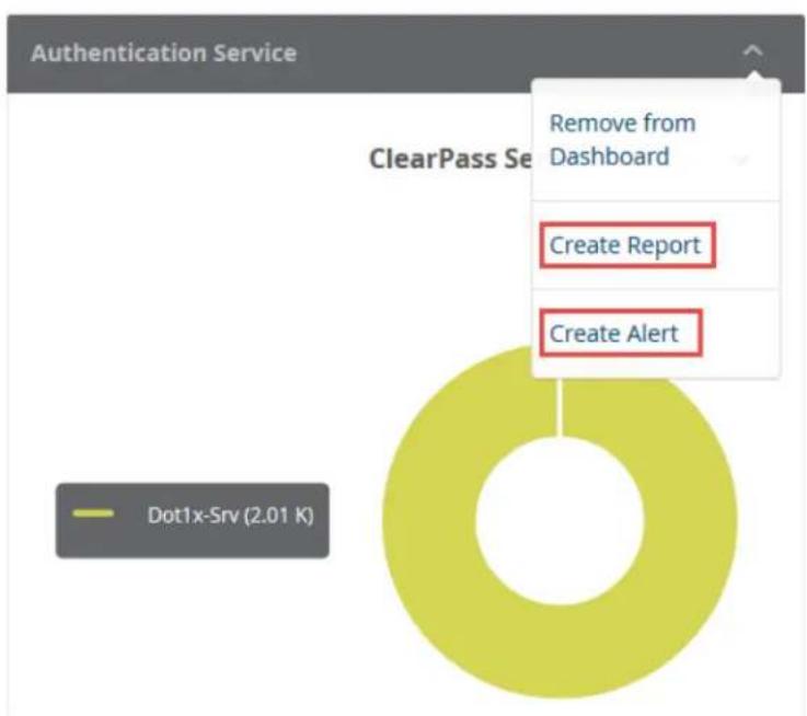
pie
| Category | Value | | ---------------- | ------ | | Create Report | 1 | | Create Alert | 1 |For detailed procedures to create reports and alerts, see Creating Reports on page 789 and Creating Alerts on page 783.
Specifying the Date Range for Data Collection
By default, the Insight widgets, including those on the Dashboard page as well as all the other Insight widgets, such as Endpoints, Guest, Posture, and so on, display information collected over the previous seven days. System Monitor widget is an exception as it displays data for the previous two hours.
You can modify the Authentication, Endpoints, Guest, Posture, and System widgets to display widget data today, one week, one month, or a custom date and time range.
To specify the date range to have data collected for a Dashboard widget:
- To specify data collection for today, one week, or one month, from the upper right corner of the Dashboard, select Today, 1w (for one week), or 1m (for one month) as desired.
The Dashboard widgets then display the information for the specified number of days.
- To specify a customized period for Insight data collection, click the Custom button.
You are prompted to specify the start and end dates for your date range, as shown in Figure 769.
Figure 769: Specifying a Custom Date Range
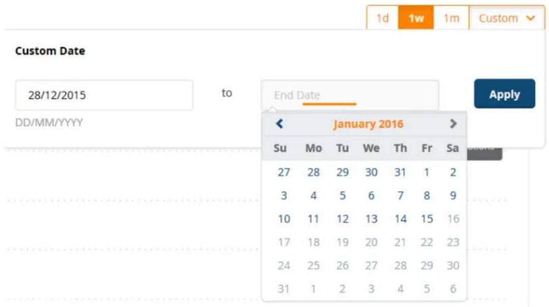
- Select the Start Date and End Date from the calendar, then click Apply.
The Dashboard widgets then display the information for the specified range of dates.
Authentication Dashboard
Authentication Dashboard widgets focus on authentication analytics and include widgets on trends, distribution, status, service, alerts, and statistics.
To access the Authentication Dashboard, navigate to Dashboard > Authentication.
Figure 770: Authentication Dashboard
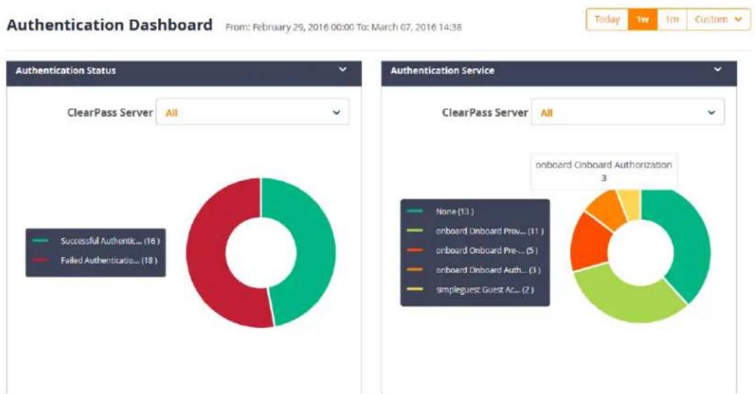
pie
| Authentication Status | Count | | ---------------------- | ----- | | Successful Authentic... | 16 | | Failed Authentication... | 18 | | ClearPass Server | None (13) | | onboard Onboard Preo... | 11 | | onboard Onboard Preo... | 5 | | onboard Onboard Preo... | 3 | | simpleguest Guest Ac... | 2 | | onboard Onboard Authorization | 3 | From: February 29, 2016 00:00 To: March 07, 2016 14:36 Today 1w 1m CustomThe following widgets are included by default on the Authentication Dashboard:
• Authentication Trend
• Authentication Distribution
• Authentication Service
• Authentication Status
• Top 10 MAC Address Authentications
• Top 20 NAD Authentications
• Top 10 Authentication Errors
- Latest 10 Authentication Alerts
For more information about the Authentication reports and the widgets provided for each report, see Authentication Category Reports on page 798.
Endpoints Dashboard
The Endpoints Dashboard widgets provide analytics that focus on Endpoint trends, distribution, device pro and bandwidth usage.
To access the Authentication Dashboard, navigate to Dashboard > Endpoints.
Figure 771: Endpoints Dashboard
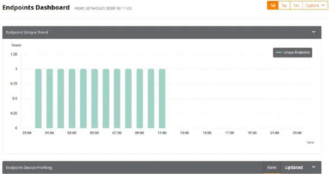
bar
| Time | Count | | ------ | ----- | | 23:00 | 1 | | 01:00 | 1 | | 03:00 | 1 | | 05:00 | 1 | | 07:00 | 1 | | 09:00 | 1 | | 11:00 | 1 |The following widgets are included by default on the Endpoints Dashboard:
• Authentication Trend
• Authentication Distribution
• Authentication Service
• Top 10 MAC Address Authentications
For more information about the Authentication reports and the widgets provided for each report, see Authentication Category Reports on page 798.
Guest Dashboard
To access the Guest Dashboard, navigate to Dashboard > Guest.
Figure 772: Guest Dashboard
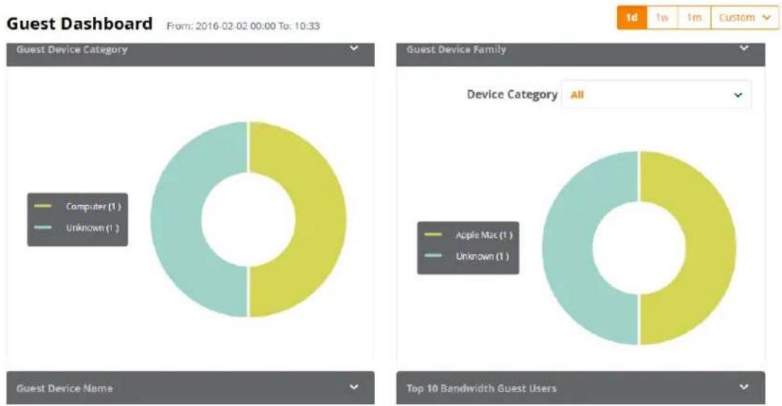
pie
| Guest Device Category | Count | | --------------------- | ----- | | Computer (1) | 1 | | Unknown (1) | 1 |The following widgets are included by default on the Guest Dashboard:
• Guests Authentication Trend
- Unique Guest Authentication
• Guests Provisioned
• Guest Device Category
• Guest Device Family
• Guest Device Name
• Top 20 Bandwidth Guest Users
For more information about the Guest reports and the widgets provided for each report, see Guest Authentication Category Reports on page 802.
Network Dashboard
To access the Network Dashboard, navigate to Dashboard > Network.
Figure 773: Network Dashboard: NAD Vendor Distribution
Network Dashboard
From: 2016-01-18 00:00 To: 2016-01-22 23:59

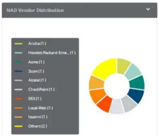
pie
NAD Vendor Distribution | Vendor | Count | |---|---| | Aruba(1) | 1 | | Hewlett-Packard-Ente_(1) | 1 | | Acme(1) | 1 | | 3com(1) | 1 | | Alcatel(1) | 1 | | CheckPoint(1) | 1 | | ERX(1) | 1 | | Local-Web(1) | 1 | | Issanni(1) | 1 | | Others(2) | 2 |The following widget is included on the Network Dashboard:
• NAD Vendor Distribution
This widget displays the list of all the NAD (Network Access Device) vendors, including the number of by each vendor. Each vendor is associated with a unique color, and those colors are reflected in the graph that displays the distribution percentage each NAD vendor represents.
For more information about the Network reports, see Network Category Reports on page 805.
Posture Dashboard
The Posture Dashboard widgets focus on device health status and device profiles. To access the Posture Dashboard, navigate to Dashboard > Posture.
Figure 774: Posture Dashboard
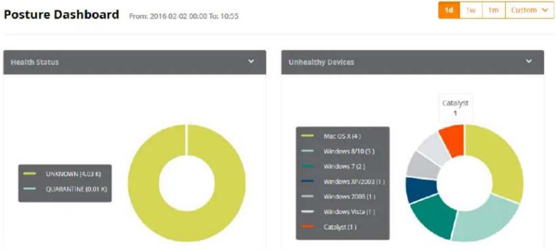
pie
Posture Dashboard | Health Status | Count | | :--- | :--- | | UNKNOWN (4.03 K) | 1 | | QUARANTINE (0.01 K) | 1 | | Unhealthy Devices | Count | | :--- | :--- | | Mac OS X (4) | 4 | | Windows 8/10 (3) | 3 | | Windows 7 (2) | 2 | | Windows XP/2003 (1) | 1 | | Windows 2008 (1) | 1 | | Windows Vista (1) | 1 | | Catalyst (1) | 1 | Catalyst: 1The following widgets are included by default on the Posture Dashboard:
• Health Status
• Unhealthy Devices
For more information about the Posture-related reports, see OnGuard Category Reports on page 806.
System Dashboard
To access the System Dashboard, navigate to Dashboard > System.
Figure 775: System Dashboard
System Dashboard From: 2016-02-02 00:00 To: 11:08

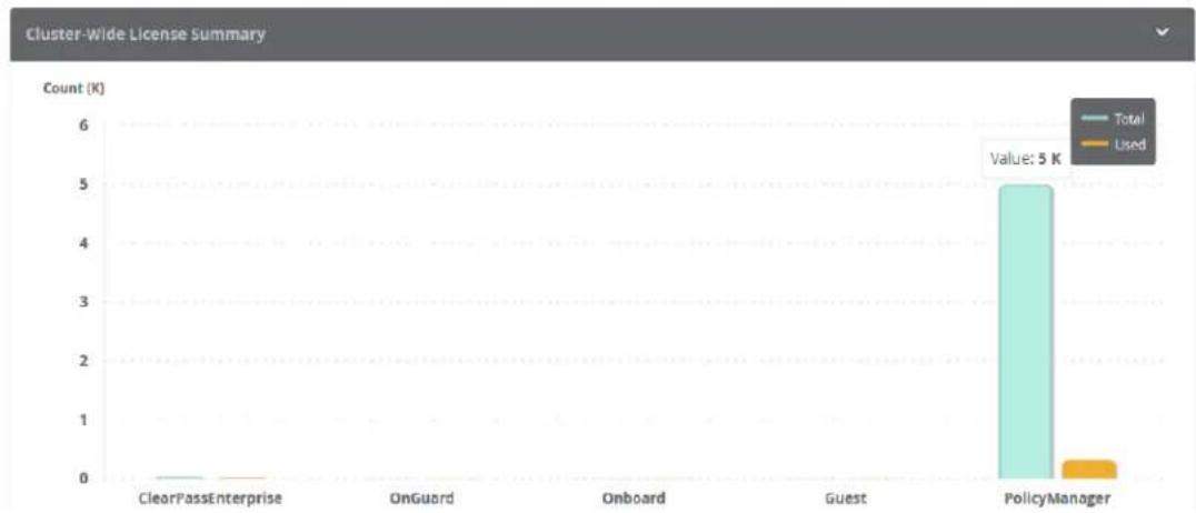
bar
Cluster-Wide License Summary | Category | Total (K) | Used (K) | |---|---|---| | ClearPassEnterprise | 0.1 | 0.1 | | OnGuard | 0.0 | 0.0 | | Onboard | 0.0 | 0.0 | | Guest | 0.0 | 0.0 | | PolicyManager | 5.0 | 0.3 | Value: 5 KThe following widgets are included by default on the System Dashboard:
• Cluster-Wide License Summary
• Policy Manager License Usage
• Guest License Usage Trend
• Top 10 Restarted Services
For more information about the System-related reports, see System Category Reports on page 811.
System Monitor Dashboard
The System Monitor Dashboard widgets focus on health, including Authentication health, processing time, CPU, memory, and disk usage.

You cannot pin System Monitor widgets to the Dashboard.
To access the System Monitor Dashboard, navigate to Dashboard > System Monitor.
Figure 776: System Monitor Dashboard
System Monitor Dashboard 2016-01-22 13:04 to 15:04
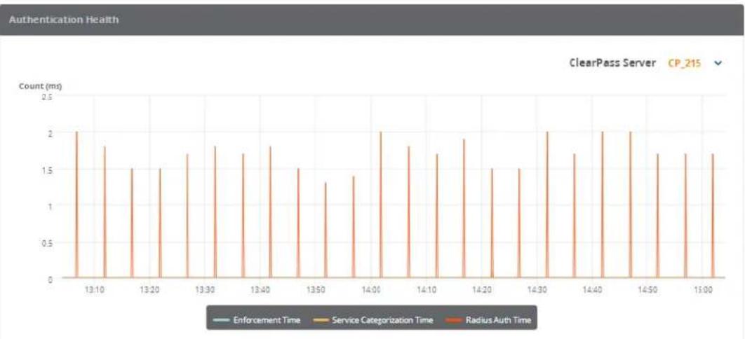
bar
Authentication Health | Time | Enforcement Time (ms) | Service Categorization Time (ms) | Radius Auth Time (ms) | |---|---|---|---| | 13:10 | 0.0 | 2.0 | 0.0 | | 13:15 | 0.0 | 1.8 | 0.0 | | 13:20 | 0.0 | 1.5 | 0.0 | | 13:25 | 0.0 | 1.5 | 0.0 | | 13:30 | 0.0 | 1.7 | 0.0 | | 13:35 | 0.0 | 1.8 | 0.0 | | 13:40 | 0.0 | 1.7 | 0.0 | | 13:45 | 0.0 | 1.8 | 0.0 | | 13:50 | 0.0 | 1.3 | 1.5 | | 13:55 | 0.0 | 1.4 | 0.0 | | 14:00 | 0.0 | 2.0 | 0.0 | | 14:05 | 0.0 | 1.8 | 0.0 | | 14:10 | 0.0 | 1.7 | 0.0 | | 14:15 | 0.0 | 1.9 | 0.0 | | 14:20 | 0.0 | 1.5 | 0.0 | | 14:25 | 0.0 | 1.5 | 0.0 | | 14:30 | 0.0 | 2.0 | 0.0 | | 14:35 | 0.0 | 1.7 | 0.0 | | 14:40 | 0.0 | 2.0 | 0.0 | | 14:45 | 0.0 | 2.0 | 0.0 | | 14:50 | 0.0 | 1.7 | 0.0 | | 14:55 | 0.0 | 1.7 | 0.0 | | 15:00 | 0.0 | 1.7 | 0.0 | ClearPass Server CP_215The following widgets are included by default on the System Monitor Dashboard:
• Authentication Health
• End-to-End Request Processing Time
• Memory Usage
- Swap Memory Usage
- Disk Usage
- CPU Usage
- CPU Load
The System Monitor Dashboard differs from the other Dashboard pages in that it can show data for two hours only (2h).
To define a custom two-hour time slot:
- Click the Custom drop-down list.
Figure 777: Specifying the Hour to Start System Monitor Scan
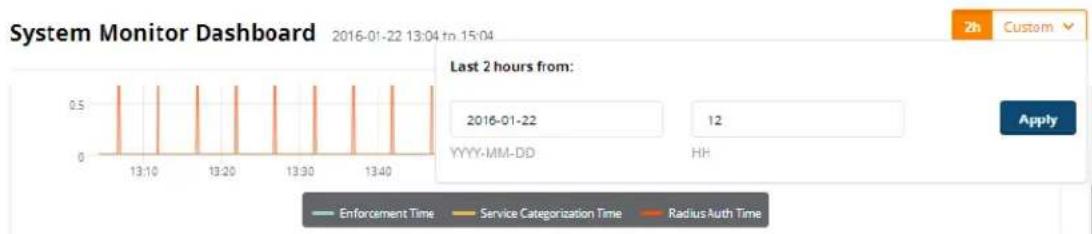
line
| Time | Enforcement Time | Service Categorization Time | Radius Auth Time | | ---------- | ---------------- | -------------------------- | ---------------- | | 2016-01-22 | 0.5 | 0.5 | 0.5 | | 2016-01-22 | 0.5 | 0.5 | 0.5 | | 2016-01-22 | 0.5 | 0.5 | 0.5 | | 2016-01-22 | 0.5 | 0.5 | 0.5 | | 2017-01-22 | 0.5 | 0.5 | 0.5 | | 2017-01-22 | 0.5 | 0.5 | 0.5 | | 2017-01-22 | 0.5 | 0.5 | 0.5 | | 2017-01-22 (Last 2 hours from) | 0.5 | 0.5 | 0.5 | | 2017-01-22 (HH) | 0.5 | 0.5 | 0.5 | | 2017-01-22 (HH) | 0.5 | 0.5 | 0.5 | | 2017-01-22 (HH) | 0.5 | 0.5 | 0.5 | | 2017-01-23 (HH) | 0.5 | 0.5 | 0.5 | | 2017-01-23 (HH) | 0.5 | 0.5 | 0.5 | | 2017-01-23 (HH) | 0.5 | 0.5 | 0.5 | | 2017-01 - HH (Last 2 hours from) | 0.5 | 0.5 | 0.5 | | 2017-01-23 (Last 2 hours from) | 0.5 | 0.5 | 0.5 | | 2017-01-23 (Last 2 hours from) | 0.5 | 0.5 | 0.5 | | 2017-01-23 (Last 2 hours from) | 0.5 | 0.5 | 0.5 | | 2017-01-23 (Last 2 hours from) | 0.5 | 0.5 | 0.5 | | 2017-01-31 (Last 2 hours from) | 0.5 | 0.5 | 0.5 | | 2017-01-31 (Last 2 hours from) | 0.5 | 0.5 | 0.5 | | 2017-01-31 (Last 2 hours from) | 0.5 | 0.5 | 0.5 | | 2017-01-48 (Last 2 hours from) | 0.5 | 0.5 | 0.5 | | 2017-01-48 (Last 2 hours from) | 0.5 | 0.5 | 0.5 | | 2017-01-48 (Last 2 hours from) | 0.5 | 0.5 | 0.6 | | Note: The last two hours are based on the last two data points in the chart.- Select the starting date.
- Click the HH field, then use the up- and down-arrows to specify the hour to start the system monitor scan. For example, specifying 13 in the HH field indicates that the start time for the two-hour period is 1:00 p.m.
- Click Apply.
Searching the Insight Database
This section provides the following information:
• About Insight Search
- Search Example
About Insight Search
Use the Insight Search feature to query the Insight database.
You can search for the following entities:
• Endpoint IP address (Framed-IP-Address)
- Clients by MAC address, hostname, or IP address
- User name
• W-ClearPass servers by name or IP address
• Network access devices by name or IP address
You can add clients and users to the Watchlist from Search results. For details, see Adding or Removing Users from the Watchlist on page 788.
The Insight Search window is always available at the top of every page.
Search works on all pages except the Report Configuration and Alert Configuration pages.
Figure 778: Search Window

Search Example
Let's take the example of searching for a MAC address:
- Start entering the MAC address into the Search window.
As you type in the MAC address in this example, Search discovers that there are two MAC addresses same initial characters:
Figure 779: Search Locating Matching Entities

- To locate the desired MAC address:
a. Click on the suggestion and see which MAC address you are looking for from the list displayed. b. Or refine your search by typing more characters to further specify the search entity.
In this example, the MAC address is identified as an Endpoint.

Figure 780: Locating and Identifying the Search Object

3. Select the search object.
The Endpoint MAC Address report is automatically displayed (see Figure 781). It includes the following information about the Endpoint:
Summary
Overview
■ Device Profile
■ OnGuard Health Information
■ Authentication Status Trend
Figure 781: Report of Search Result
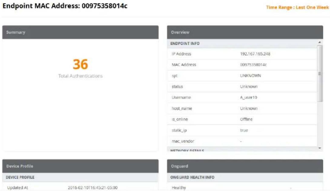
Creating Alerts
This section provides the following information:
- Introduction
- Creating New Alerts
• Modifying the User Watchlist - Adding or Removing Users from the Watchlist
Introduction
Alerts provide network managers with near-real-time messages on anomalous network activity. Such activi could consist of:
- Irregular authentication activity
- Irregular network device access activity
- Users attempting privileged commands on network devices
- Irregular activity on the W-ClearPass servers
Reports and alerts include templates for easy configuration. These templates allow you to quickly configure and monitor network activity. In addition to email notifications, you can also send alerts to mobile device SMS, providing the capability to receive mission-critical information on the go.

Any Error-level System Event/Event Viewer entries in W-ClearPass servers are notified with a System Alert Notification.
Creating New Alerts
To create a new alert:
- Navigate to the Alerts page.
Figure 782: Alerts Configuration Page
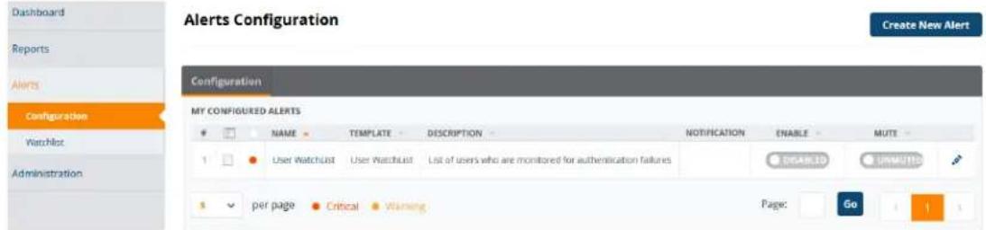
■ Enable button: From the switch, you can enable or disable the selected alert.
■ Mute button: Allows you to mute alert output while you work to address the alert.
- Click Create New Alert.
Figure 783: Creating a New Alert
Create New Alert
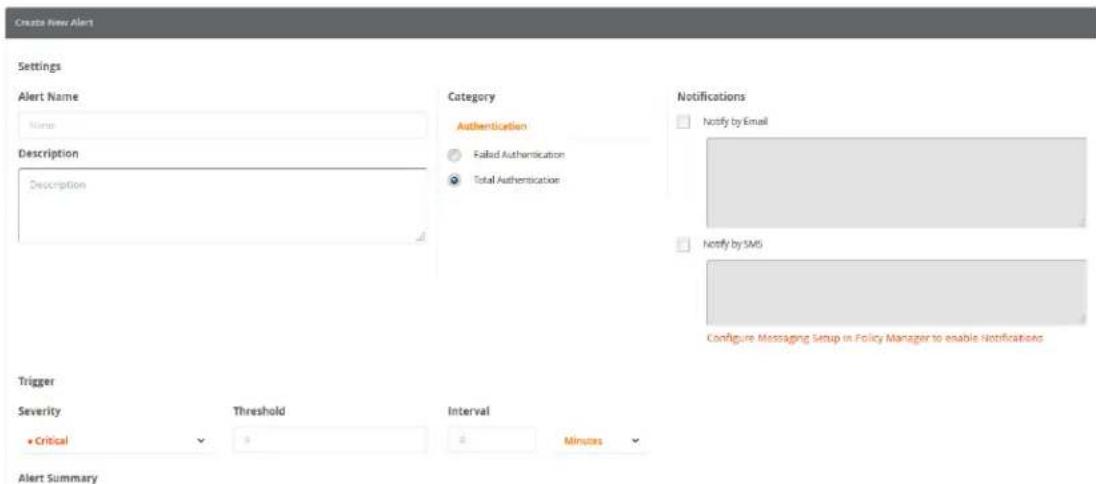
- Enter the information for each Alert parameter as described in Table 393.
Table 393: Create New Alert Parameters
| Alert Field Action/Description | |
| Alert Name 1. Enter the name of the alert. | |
| Description 2. Optionally, enter a summary description of the alert. | |
| Category | 3. Select the alert Category, then specify the desired alert type in the selected category:■ Authenticationa. Failed Authenticationb. Total Authentication■ System■ TACACSa. TACACS Commandsb. TACACS Failures |
| Notifications 4. Specify report notifications.■ Notify by Email. When you select this option, enter the list of email addresses to be notified. The alert notification is sent whenever the trigger threshold is met.NOTE: Enabling Notify by Email is mandatory.■ Notify by SMS. When you select this option, enter the phone numbers of each recipient. The alert notification is sent whenever the trigger threshold met.NOTE: A warning message appears if you have not configured the SMTP mail server for email notifications. To do so, from the Policy Manager, navigate to Administration > External Servers > Messaging Setup. | |
| Trigger Severity | 5. From the Trigger Severity drop-down, select one of the following:■ Critical■ Warning |
| Trigger Threshold | 6. Specify Threshold and Interval values as criteria for determining whether an alert is necessary.For example, if you specify the threshold as 25 and the interval as 15 minutes, once the threshold of 25 is met within 15 minutes, an alert is triggered. |
| Trigger Interval | 7. Specify the Interval, then select Minutes or Hours. |
| Alert Summary | When you have configured the alert settings, the Alert Summary displays the settings for your review. |
| 8. Click Save. | |
Modifying the User Watchlist
A Watchlist is a list of VIPs, executives, and devices known to be problematic that are monitored for authentication failures. W-ClearPass collects all user authentication status.
When W-ClearPass finds a user defined in the Watchlist that both fails to authenticate and also matches Watchlist triggers (severity, threshold, and interval), an alert notification is sent to the notification list via
or to mobile devices via SMS. This allows the authentication failure to be resolved proactively before the problem is reported by the user.
The Watchlist generates an alert only when an unsuccessful authentication for a specific device occurs.
Default Watchlist Trigger Settings
The default Watchlist trigger settings are as follows:
• Severity = Critical
- Threshold = 1
- Interval = 30 seconds

You cannot edit the The Watchlist trigger settings.
To modify the User Watchlist:
- From the Insight navigation panel, choose Alerts, then select Watchlist. The User Watchlist opens (see Figure 784).
Figure 784: User Watchlist
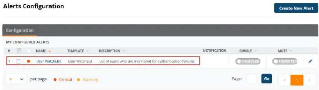
The users who are currently on the Watchlist are displayed. By default, the User Watchlist includes the Authentication Trend report widget.
- Click Modify Watchlist.
The Edit Alert page appears.
Figure 785: Modifying the User Watchlist
Edit Alert
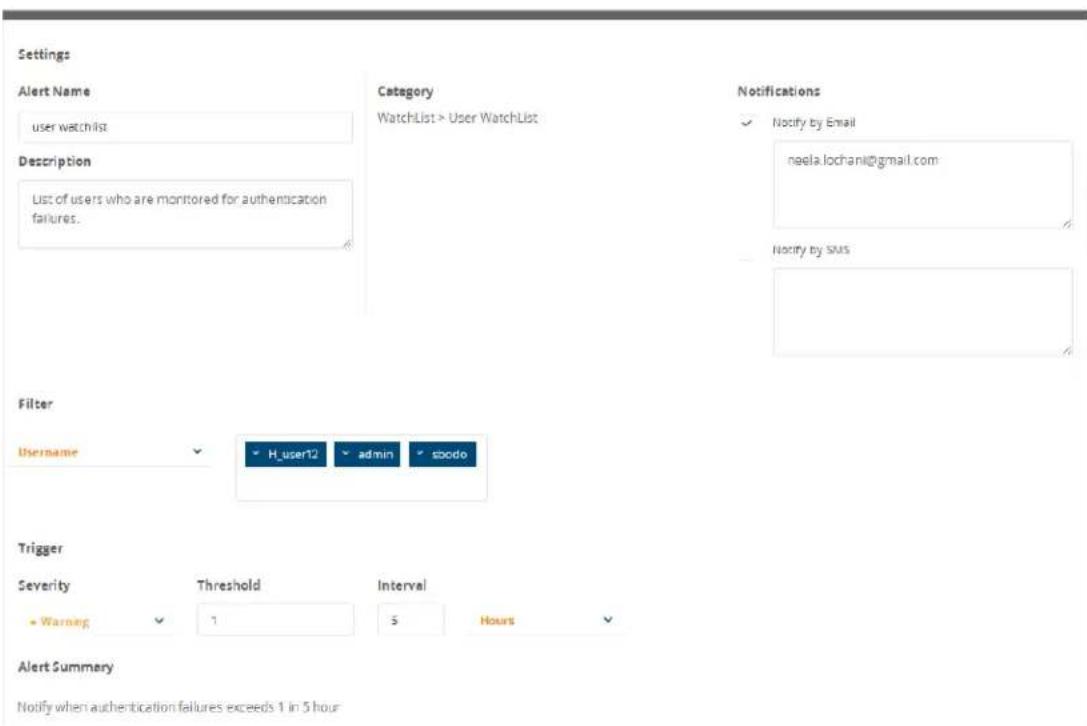
- Enter the desired settings for each User Watchlist parameter as described in Table 394.
Table 394: Modify User Watchlist Parameters
| Alert Field Action/Description | |
| Alert Name 1. Optionally, you can modify the name of the User Watchlist. | |
| Description 2. Optionally (and recommended), enter a summary description of the User Watchlist. | |
| Category | The Category is set to Alert >User Watchlist. This is not an editable field. |
| Notifications 3. Specify Watchlist notifications.■ Notify by Email. When you select this option, enter the list of email addresses to be notified. The alert notification is sent whenever the threshold is met.■ Notify by SMS. When you select this option, enter the phone numbers of each recipient. An SMS message is sent with an alert notification whenever thres is met.NOTE: A warning message appears if you have not configured the SMTP mail ser email notifications. To do so, navigate to Administration >External Servers>Messaging Setup. | |
| Filter:Username | The User Watchlist has only one filter:Username.4. From the Username drop-down, select one or more users to add to the WatchFilter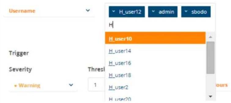 |
| Alert Summary | When you have configured the Watchlist settings, the Alert Summary displays the settings for your review. |
| Save your changes 5. Click Save. | |
Adding or Removing Users from the Watchlist
You can use the Insight Search function to add users to or remove users from the Watchlist.
Adding a User to the Watchlist
To add a user to the Watchlist:
- In the Insight Search window, enter the name of the user.
The Insight User Information page for the selected user is displayed.
Figure 786: Insight User Information Page
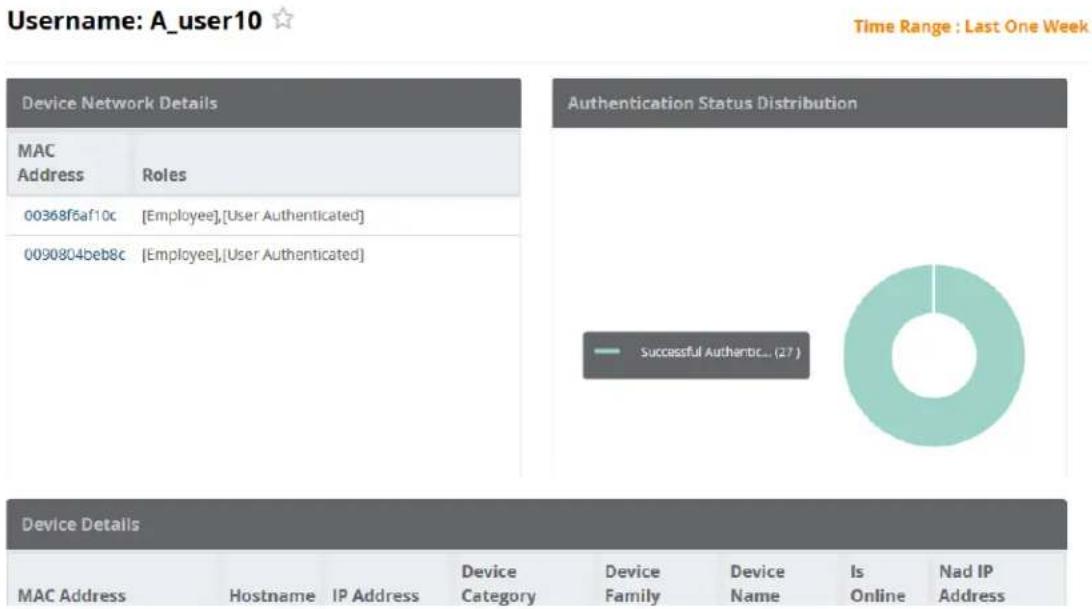
- To add a user to the Watchlist, click the star icon next to the username as shown in Figure 786.
The User Information page now displays the following information:
Figure 787: User Successfully Added to Watchlist
![A_user10 added to user watchlist successfully. Please configure sms/email notifications. Username: A_user10 ★ Device Network Details MAC Address Roles 00368f6af10c [Employee],[User Authenticated] 0090804beb8c [Employee],[User Authenticated]](/content/2026/05/842116/images/27d085c3b2dcb16f9ae8333e5d61e6dd1d1c0af693180d680669769d3ad959c2.jpg)
The star icon color is now set to orange, indicating the user has been added to the Watchlist.
The following message is displayed:
Removing a User from the Watchlist
To remove a user from the Watchlist:
- In the Insight Search window, enter the name of the user.
The Insight User Information page for the selected user opens.
Figure 788: Removing a User from the Watchlist
Username: A_user10 ★
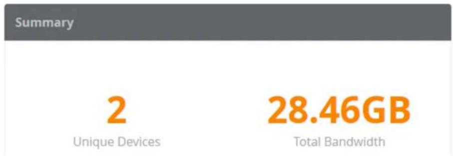
- Click the orange star icon next to the username.
The user is removed from the Watchlist. The star icon is now white. You receive the following message
Creating Reports
This section provides the following information:
Overview
- Settings Configuration
• Report Filters Configuration
• Specifying the Logo and Branding
• Report Summary Page
- Configured Reports Page
• Viewing Reports
Overview
The Reports page provides a method for creating reports with data filters and customized time ranges up to the previous two months.
Figure 789: Reports Page
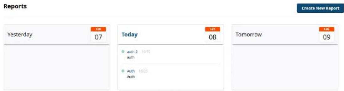
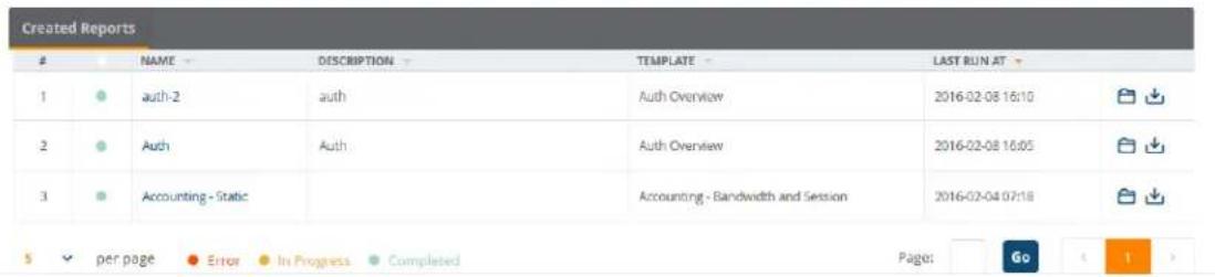
Run Reports Now or on a Specified Schedule
You can set up reports to run immediately or you can schedule a report to run on a daily, weekly, or basis. Although Insight reports show data over the previous two-month period, Insight can retain data for to two years.
Select Report Filters
Many reports allow you to select filters that include a simple AND condition. For example, you can use create a report that displays data for RADIUS Authentications from the Active Directory AND the Guest U Repository source.
PDF, CSV, and HTML Report Formats Are Available
After a report is configured and run, the report is available for download in PDF and CSV formats. You open a report and view it in HTML format.
Deleting a configured report deletes both the report configuration and all related report output.

Settings Configuration
To create a new report:
- From the Insight navigation panel, click Reports.
- Select Create New Report.
The Settings page of the Create New Report Wizard opens.
Figure 790: Create New Report Wizard: Settings
Create New Report

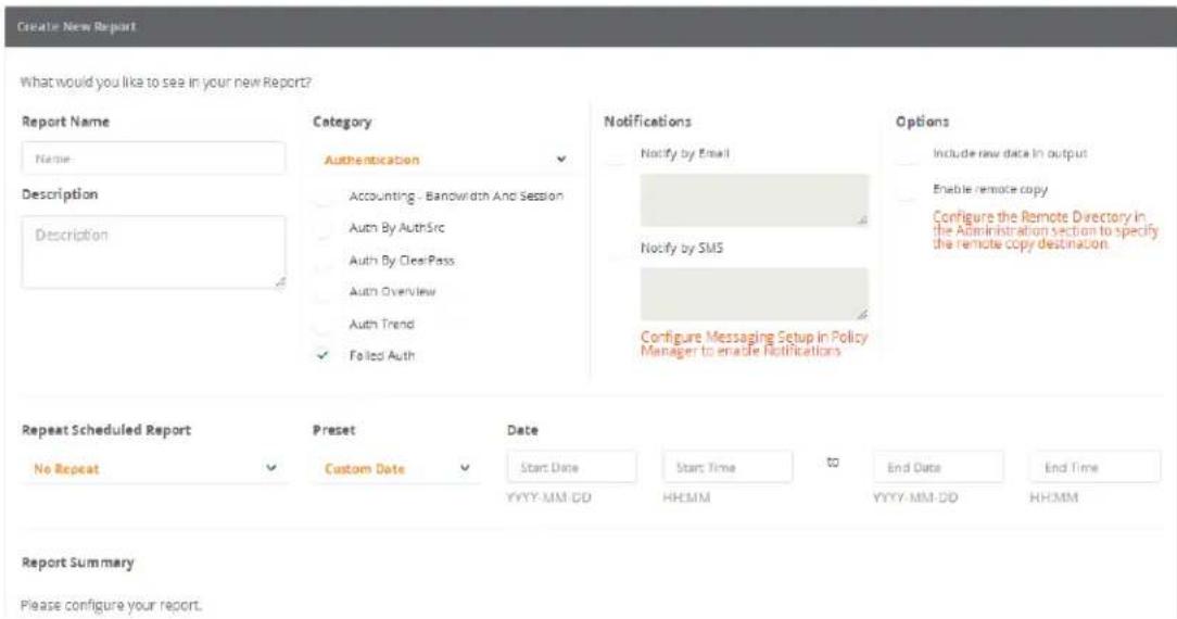
- Enter the appropriate information as described in Table 395.
Table 395: Specifying the Report Settings Parameters
| Report Parameter Action/Description | |
| Report Name 1. Enter the name of the report. | |
| Description 2. Optionally, enter a summary description of the report. | |
| Category | 3. Select the report Category, then specify the desired report type in the selected category:■ Authentication■ Endpoint■ Guest Authentication■ Network■ OnGuard■ Onboard■ RADIUS Authentication■ System■ TACACSNOTE: For detailed information about what report types are provided for each report category, see Insight Report Categories Reference on page 798. |
| Notifications 4. Optionally, specify report notifications.■ Notify by Email. When you select this option, enter the list of email addresses to be notified.■ Notify by SMS. When you select this option, enter the phone numbers of each recipient (separated by commas).NOTE:A warning message appears if you have not configured the SMTP mail server for email notifications. To do so, from the Policy Manager, navigate to Administration > External Servers > Messaging Setup. For details, see Messaging Setup on page 603. | |
| Options NOTE: Before you can enable one or both of these two options, you must configure the File Transfer Settings (including the Remote Directory) in the Administration section. For more information, see File Transfer Settings Configuration on page 814.· Include raw data in outputA full set of raw data is customizable in the CSV reports only.· Enable remote copyThis option lets you copy reports to the location specified in the Administration > Remote Directory setting. | |
| Repeat Scheduled Report | 5. Specify whether you want to generate this report Daily, Weekly, or Monthly. The default is No Repeat.■ To rerun a No Repeat report or a static report, edit and save the report. Insight will then automatically run the report.■ When you create a report with the No Repeat option selected, the report runs when you click Save.■ When you create a periodic report (Daily, Weekly, or Monthly), the report is run according to the specified schedule. |
| Preset Date Range | 6. You can choose to specify a Preset Date Range for this report:■ Custom DateWhen you select Custom Date, specify the Start Date and Time and the End Date and Time.■ Today■ Since Yesterday■ This Week■ Within Last Week■ Within Last 2 Weeks■ This Month■ Within Last MonthWhen you select one of these date range options (with the exception of Custom Date), Insight automatically populates the Start Date/Time and End Date/Time settings. |
| Report Summary | When you have configured the report settings, the Report Summary displays them for your review. |
| 7. Click Next. | |
Report Filters Configuration
When you complete the Settings page in the Create New Report wizard and click Next, the page that opens allows you to configure the filters for your report. Each type of report has a specific set of filters available. Report filters apply the data fetched from the database, then Insight displays the result in the report. The filters that are available depend on the report category you specify.
If you don't apply a filter, Insight includes all the data in the generated report that matches the report category.
Figure 791: Specifying a Report Filter
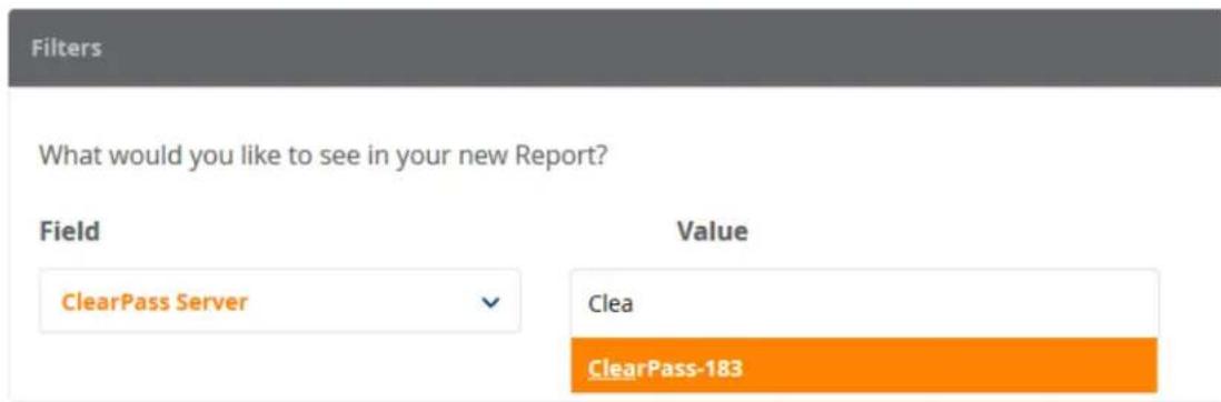
To specify a report filter:
- Field: From the Field drop-down, select the parameter you wish to filter on.
- Value: From the Value drop-down, select the appropriate value.
As you enter characters in the Value field, Insight searches for the matching value.
Specifying the Logo and Branding
When you complete the report filters configuration, scroll to the Logo and Branding section on the same page.
The initial Logo and Branding screen presents a prompt, asking if you want to change the logo:
Figure 792: Prompt for Changing the Logo

- If you don't wish to change the logo, simply click Next to proceed.
- If you do want to change the logo, click the check box.
The Logo and Branding configuration section opens:
Figure 793: Logo and Branding Section
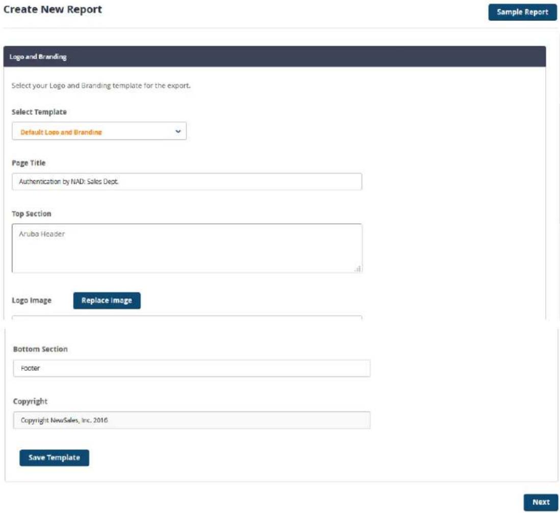
To specify the logo and branding information:
- Enter the information as described in Table 396, then click Next.
Table 396: Specifying Logo and Branding Parameters
| Report Parameter Action/Description | |
| Select Template 1. From the | drop-down, select the logo and branding template. |
| Page Title 2. Enter the page | title. |
| Top Section 3. Enter the header for the top of the page. | |
| Logo Image | 4. To browse to the appropriate logo image, clickReplace Image. |
| Bottom Section | 5. Enter the footer text. |
| Copyright | 6. Enter the copyright information. For example, "Copyright 2016 NewSales, Inc." |
| Save Template | 7. To save the new branding and logo settings, clickSave Template. |
Report Summary Page
When you complete the Logo and Branding section, the Report Summary is displayed.
Figure 794: Report Summary
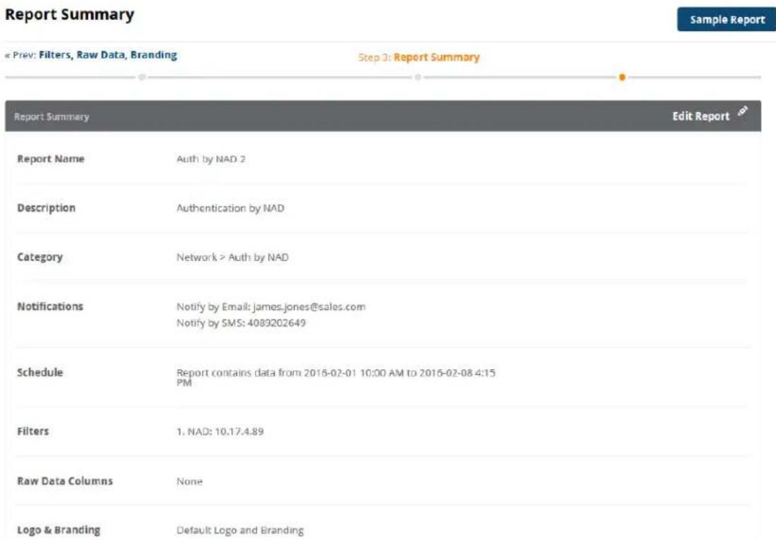
- Review the Report Summary.
a. If you wish to change any aspect of the report, click Edit Report.
The Report Summary dialog opens. You can edit the current report settings as needed.
b. Make any necessary changes, then click Save.
- When the report settings are satisfactory, click Save.
Insight generates the report. You return to the Configured Reports page.
Configured Reports Page
To see the set of configured reports, select Reports > Configuration.
The Configured Reports page opens.
Figure 795: Configured Reports Page
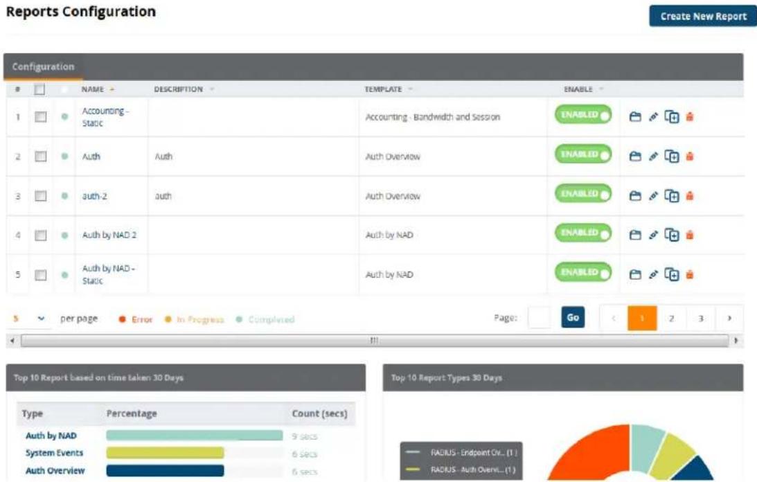
The blue dot next to a report name indicates that the report generation is complete.
From this view, you can edit, copy, or delete a configured report.
This page also provides two report widgets:
• Top 10 Reports Time to Run 30 Days
This widget lists the ten reports that took the longest (in seconds) to run over the last 30 days.
• Top 10 Reports Last 30 Days
This widget lists the ten most frequently run reports over the last 30 days.
Viewing Reports
To view a generated report:
- From the navigation panel, click Reports.
- Scroll to the Created Reports section.
Figure 796: Created Reports
Reports
Create New Report
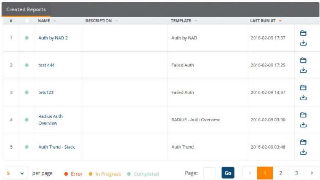
- To download the zip file that contains the reports in PDF and CSV formats, click the Download icon (as shown in Figure 796).
- To view the desired report in HTML format (which opens in new tab), click the name of the report. The generated report is displayed (see Figure 797).
Figure 797: Report Displayed in HTML Format

Title
Report Name: authentication
Report Template: Auth By ClearPass
Report contains data from 2016-01-27 14:14 to 2016-02-01 14:14 PST
Aruba Header
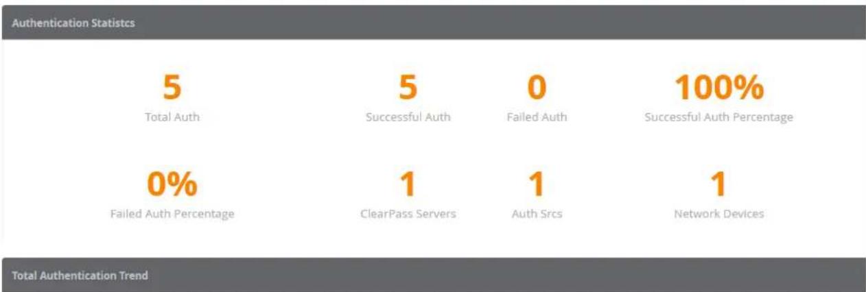
other
| Authentication Statistics | Total Auth | Failed Auth Percentage | Successful Auth | Failed Auth | Successful Auth Percentage | | --- | --- | --- | --- | --- | --- | | 5 | 0% | 1 | 1 | 0 | 100% | | 0 | 0% | 1 | ClearPass Servers | 1 | 1 | | Total Authentication Trend | 0% | 1 | ClearPass Servers | 1 | 100% |Insight Report Categories Reference
This section provides the following information:
- Introduction
• Authentication Category Reports
• Endpoint Category Reports
• Guest Authentication Category Reports
• Network Category Reports
• OnGuard Category Reports - Onboard Category Report
• RADIUS Authentication Category Reports
• System Category Reports
• TACACS Category Reports
Introduction
This section provides detailed information about each of the report types and their associated widgets available for each Insight Report category. The Insight report templates are organized into categories, which each category has multiple report types that each contain a unique set of report data.
The following sections describe each report category, including the available reports within each category, the contents of each report.
Authentication Category Reports
The reports available in the Authentication category described in Table 397 provide the list of authentications that occurred during the report duration.
Additional authentication statistics are displayed on the Authentication Dashboard. For more information, see Authentication Dashboard on page 776.
Table 397: Authentication Category Reports
| Report Type Report Widgets | |
| Accounting—Bandwidth and SessionProvides the statistics using the accounting data generated during report duration.This report allows you to filter the report data by:W-ClearPass serverNetwork access device IP addressDevice categoryDevice familyDevice nameSSIDEndpoint IP addressUser name | This report type includes the following bandwidth and session information:Bandwidth Statistics: Total Bandwidth, Average Bandwidth, Maximum Bandwidth, Maximum Upstream Bandwidth, Maximum Downstream Bandwidth, Sessions, Maximum Duration, Users, EndpointsUpstream Bandwidth and Downstream Bandwidth TrendTotal Bandwidth and Average Bandwidth TrendAverage Session Time TrendUnique Session TrendTop 10 Device Categories with Most Bandwidth ConsumedTop 10 Device Categories with Most SessionsTop 10 Device Categories with Most DurationTop 10 Device Families with Most Bandwidth ConsumedTop 10 Device Families with Most SessionsTop 10 Device Families with Most DurationTop 10 Endpoints with Most Bandwidth ConsumedTop 10 Endpoints with Most SessionsTop 10 Endpoints with Most DurationTop 20 Users with Most Bandwidth ConsumedTop 10 Users with Most SessionsTop 10 Users with Most DurationDomain Summary: Provides an overview of authentications per domain. |
| Authentication by Authentication SourceProvides the statistics for successful and failed authentications per authentication source. | This report type includes the following information:Authentication StatisticsTotal Authentication TrendFailed Authentication TrendAuthentication Distribution Across Authentication SourceAuthentication Distribution Across Authorization SourceAuthentication Distribution Across Authentication SourceNOTE: This report allows you to filter the report data by authentication source. |
| Authentication by W-ClearPassProvides the statistics for successful and failed authentications per W-ClearPass servers in a cluster. | This report type includes the following information:Authentication StatisticsTotal Authentication TrendFailed Authentication TrendAuthentication Distribution—Error TypesAuthentication Distribution Across ServiceTop 10 W-ClearPass with Most AuthenticationsTop 10 W-ClearPass with Most Failed AuthenticationsTop 10 W-ClearPass with Most MAC Address AuthenticationsTop 10 W-ClearPass with Most UsersNOTE: This report allows you to filter the report data by W-ClearPass Policy Manager server. |
| Authentication OverviewProvides statistics in general for the report duration, such as total authentications per day, unique devices authentications trend by day, unique users authentication trend by day, authentication distribution based on authentication status, service, W-ClearPass server, SSID, VLAN, enforcement profile, authentication source, and top 10 users with most authentications, and so on. | This report type includes the following information:• Authentication Statistics• Total Authentication Trend• Authentication Status Trend• Unique Devices Authentication Trend• Unique Users Authentication Trend• Authentication Distribution Across Auth Status• Authentication Distribution Across Cluster• Authentication Distribution Across Service• Authentication Distribution Across VLAN• Authentication Distribution Across SSID• Authentication Distribution Across Enforcement Profiles• Authentication Distribution Across Role• Authentication Distribution Across Authentication Source• Top 10 Users with Most Authentications• Top 10 MAC Addresses with Most Authentications• Top 10 Services with Most Authentications• Top 10 Auth Sources with Most Authentications• Top 10 W-ClearPass Roles Assigned• Top 10 Authorization Sources• Top 20 NADs with Most Authentications• Top 10 Enforcement Profiles UsersNOTE: This report allows you to filter the report data by W-ClearPass Policy Manager host name, Network Attached Device (NAD) IP address, SSID, and Error Code. |
| Authentication TrendProvides authentication trend statistics for today and yesterday, today and the same day a week ago, and so on. | This report type includes the following information:• Authentication Statistics• Total Authentication Trend• Authentication Trend for Today and Yesterday• Authentication Trend for Today and Same Day Week Ago• Total Authentication for 1 Month (per month)NOTE: This report allows you to filter the report data by W-ClearPass Policy Manager host name, Network Access Device (NAD) IP address, and SSID. |
| Failed AuthenticationProvides statistics based on failed authentications. | This report type includes the following information:• Error Statistics• Failed Authentication Trend• Authentication Distribution—Error Types• Failed Authentication Distribution across Service• Failed Authentication Distribution across Authentication Source• Top 10 Errors with Most Failed Authentications• Top 20 NADs with Most Failed Authentications• Top 10 W-ClearPass Servers with Most Failed Authentications• Top 10 Users with Most Failed AuthenticationsTop 10 Endpoints with Most Failed AuthenticationsTop 10 Services with Most Failed AuthenticationsNOTE: This report allows you to filter the report data by W-ClearPass Policy Manager host name, Network Access Device (NAD) IP address, SSID, and Error Code. |
Endpoint Category Reports
The Endpoint category provides information on endpoints discovered during the report duration.
The reports available in the Endpoint category described in Table 398 contain data that can also be found in the Endpoints widgets on the Endpoints Dashboard.
For additional information about the Endpoints Dashboard, see Endpoints Dashboard on page 777.
Table 398: Endpoint Category Reports
| Report Type Report Widgets | |
| Endpoint Authentication Overview This report type includes the following information for all endpoint types: Endpoint Statistics Endpoints Distribution Across Device Category Endpoints Distribution Across Device Family Endpoints Distribution Across Device Name Top 10 Users with Most Endpoints Top 10 Device Categories with Most Endpoints Top 10 Device Names with Most Endpoints Top 10 Device Families with Most EndpointsNOTE: This report also allows you to filter the report data Network Access Device (NAD) IP address, Device Category, Device Family, Device name, and SSID. | |
| Endpoint Overview This report type includes the following information for all endpoint types: Top 10 Reports Time to Run 30 Days Top 10 Reports Last 30 Days | |
| Guest—Endpoint Overview | This report type includes the following information for endp using Guest Authentication: Endpoint Statistics Endpoints Distribution Across Device Category Endpoints Distribution Across Device Family Endpoints Distribution Across Device Name Top 10 Users with Most Endpoints Top 10 Device Categories with Most Endpoints Top 10 Device Names with Most Endpoints Top 10 Device Families with Most EndpointsNOTE: This report also allows you to filter the report data by Network Access Device (NAD) IP address, Device Category, Device Family, Device name, and SSID. |
| RADIUS—Endpoint Overview This report type includes the following information for endpoints using RADIUS authentication:• Endpoint Statistics• Endpoints Distribution Across Device Category• Endpoints Distribution Across Device Family• Endpoints Distribution Across Device Name• Top 10 Users with Most Endpoints• Top 10 Device Categories with Most Endpoints• Top 10 Device Names with Most Endpoints• Top 10 Device Families with Most EndpointsNOTE: This report also allows you to filter the report data by Network Access Device (NAD) IP address, Device Category, Device Family, Device name, and SSID. | |
Guest Authentication Category Reports
The reports available in the Guest Authentication category described in Table 399 provide statistics based on Guest authentications from the Guest database. The statistics for authentication trend and usage for guest users are drawn from the accounting data.
Additional authentication statistics are displayed on the Guest Dashboard. For additional information about the Guest Dashboard, see Guest Dashboard on page 778.
Table 399: Guest Authentication Category Reports
| Report Type Report Widgets | |
| Guest—Auth Overview This report includes the following report widgets:Authentication StatisticsTotal Authentication TrendAuthentication Status TrendUnique Devices Authentication TrendUnique Guests Authentication TrendAuthentication Distribution Across Authentication StatusAuthentication Distribution Across ClusterAuthentication Distribution Across ServiceAuthentication Distribution Across VLANAuthentication Distribution Across SSIDAuthentication Distribution Across Enforcement ProfilesAuthentication Distribution Across RolesAuthentication Distribution Across Authentication SourceTop 10 Guests with Most AuthenticationsTop 10 MAC Addresses with Most AuthenticationsTop 10 IPs with Most AuthenticationsTop 10 Services with Most AuthenticationsTop 10 Authentication Sources with Most AuthenticationsTop 10 ClearPass Roles AssignedTop 10 Authorization Sources with Most AuthenticationsTop 20 NADs with Most AuthenticationsTop 10 Enforcement Profiles UsedNOTE:This report also allows you to filter the report data by W-ClearPas name and Network Access Device (NAD) IP address. | |
| Guest—Auth Trend This report includes the following report widgets:Authentication StatisticsTotal Authentication TrendAuthentication Trend for Today and YesterdayAuthentication Trend for Today and Same Day Week AgoTotal Authentication for One MonthSponsor ListNOTE:This report also allows you to filter the report data by W-ClearPas Policy Manager host name and Network Access Device (NAD) IP address. | |
| Guest—Auth by W-ClearPass This report type includes the following information guest authentications by W-ClearPass:Authentication StatisticsTotal Authentication TrendFailed Authentication TrendAuthentication Distribution—Error TypesAuthentication Distribution Across ServiceTop 10 W-ClearPass with Most AuthenticationsTop 10 W-ClearPass with Most Failed AuthenticationsTop 10 W-ClearPass with Most MAC AuthenticationsTop 10 W-ClearPass with Most Guests | |
| NOTE: This report also allows you to filter the report data by W-ClearPass Policy Manager host name. | |
| Guest—Social Login This report type includes the following information for guest authentication for Social Logins:Social Authentication TrendEndpoint Distribution Across Social ProvidersAuthentication Distribution Across Authentication SourceNOTE: This report also allows you to filter the report data by W-ClearPass host name and Network Access Device (NAD) IP address. | |
| Guest Accounting—Bandwidth and SessionThis report allows you to filter the report data by:W-ClearPass serverNetwork access device IP addressDevice categoryDevice familyDevice nameSSIDEndpoint IP addressUser name | This report type includes the following bandwidth and session information:Bandwidth Statistics: Total Bandwidth, Average Bandwidth, Maximum Bandwidth, Maximum Upstream Bandwidth, Maximum Downstream Bandwidth, Sessions, Maximum Duration, Guests, EndpointsUpstream Bandwidth and Downstream Bandwidth TrendTotal Bandwidth and Average Bandwidth TrendAverage Session Time TrendUnique Session TrendTop 10 Device Categories with Most Bandwidth ConsumedTop 10 Device Categories with Most SessionsTop 10 Device Categories with Most DurationTop 10 Device Families With Most Bandwidth ConsumedTop 10 Device Families With Most SessionsTop 10 Device Families With Most DurationTop 10 Endpoints with Most Bandwidth ConsumedTop 10 Endpoints with Most SessionsTop 10 Endpoints with Most DurationTop 20 Guests with Most Bandwidth ConsumedTop 10 Guests with Most SessionsTop 10 Guests with Most Duration |
| Guest Devices—Expired The Guest Devices—Expired report lets you view information about expired guest devices.This report type includes the following report widgets:Guest Expiry StatisticsGuest Expiry List (MAC Address and Device Name) | |
| Guest Users and Devices—Expired | The Guest Users and Devices—Expired report lets you view information about expired guest accounts and devices.This report type includes the following report widgets:Guest Expiry StatisticsGuest Expiry List (MAC Address and Visitor Name) |
| Guest Users—Expired | The Guest Users—Expired report lets you view information about expired guest accounts.This report type includes the following report widgets:Guest Expiry StatisticsGuest Expiry List |
Network Category Reports
The reports available in the Network category described in Table 400 contain data about network access devices and ives details on authentication trends such as successful and failed authentications on a per-c basis.
Similar information can also be found in the Network widgets on the Network Dashboard. For additional information, see Network Dashboard on page 779.
Table 400: Network Category Reports
| Report Type Report Widgets | |
| Authentication by NAD This report type includes the following information for Network Access Devices (NADs) using guest authentication. • Authentication Statistics • Total Authentication Trend • Failed Authentication Trend • Authentication Distribution Across NAD Ports • Top 20 NADs with Most Authentication • Top 10 Services with Most Authentications • Top 20 NADs with Most Failed Authentications • Top 20 NADs with Most MAC Addresses • Top 20 NADs with Most UsersNOTE:This report also allows you to filter the report data by NAD IP address. | |
| Guest—Authentication by NAD This report type includes the following information for Network Access Devices (NADs) using guest authentication • Authentication Statistics • Total Authentication Trend • Failed Authentication Trend • Authentication Distribution Across NAD Ports • Top 20 NADs with Most Authentication • Top 10 Services with Most Authentications • Top 20 NADs with Most Failed Authentications • Top 20 NADs with Most MAC Addresses • Top 20 NADs with Most GuestsNOTE:This report also allows you to filter the report data by NAD IP address. | |
| RADIUS—Auth by NAD This report type includes the following information for Network Access Devices (NADs) using guest authentication: • Authentication Statistics • Authentication Distribution Across NAD Ports • Top 20 NADs with Most Authentication • Top 10 Services with Most Authentications • Top 20 NADs with Most Failed Authentications • Top 20 NADs with Most MACs • Top 20 NADs with Most UsersNOTE:This report also allows you to filter the report data by NAD IP address. | |
OnGuard Category Reports
The reports available in the OnGuard category provide analysis on the devices' posture and health status. These widgets contain data that can also be found in the Posture widgets on the Posture Dashboard. For additional information, see Posture Dashboard on page 779.
Table 401: OnGuard Category Reports
| Report Type Report Widgets | |
| Apple Mac Endpoint Posture | This report type includes the following posture information for Apple/Macintosh endpoints:OnGuard StatisticsOnGuard Device Authentication TrendOnGuard Device Distribution Across Health StatusAntispyware Product NameAntspyware Dat File VersionAntispyware Engine VersionOnGuard Device Distribution Across Antispyware Real-Time Protection StatusAntispyware VersionAntivirus Product NameAntivirus Dat File VersionAntivirus Engine VersionOnGuard Device Distribution Across Antivirus RealTimeProtection StatusAntivirus VersionDisk Encryption Product NameDisk Encryption VersionFirewall Product NameOnGuard Device Distribution Across Firewall StatusFirewall VersionOnGuard Device Distribution Across Network Connection TypeOnGuard Device Distribution Across P2P Application NameOnGuard Device Distribution Across P2P StatusOnGuard Device Distribution Across Patch Agent NameMissing Patches CountOnGuard Device Distribution Across Patch Agent StatusOnGuard Device Distribution Across Client Operating SystemOnGuard Device Distribution Across Client Running as VMNOTE: This report also allows you to filter the report data by System Posture Token (SPT). |
| Endpoint Posture Overview This report type includes the following endpoint posture information:OnGuard StatisticsOnGuard Device Distribution Across Health StatusUnhealthy OnGuard Device Distribution Across Device FamilyOnGuard Device Distribution Across Agent TypeOnGuard Device Distribution Across Agent VersionHealth ClassMissing HotfixesNOTE: This report also allows you to filter the report data by System Posture Token (SPT). | |
| Linux Endpoint Posture This report type includes the following posture information for endpoints using a Linux operating system:OnGuard StatisticsOnGuard Device Authentication Trend | OnGuard Device Distribution Across Health StatusAntivirus Product NameAntivirus Dat File VersionAntivirus Engine VersionOnGuard Device Distribution Across Antivirus RealTimeProtection StatusAntivirus VersionNOTE: This report also allows you to filter the report data by System Posture Token (SPT). |
| Windows Endpoint Posture | This report type includes the following posture information for endpoints using a Windows operating system:OnGuard StatisticsOnGuard Device Authentication TrendOnGuard Device Distribution Across Health StatusAntispyware Product NameAntspyware Dat File VersionAntispyware Engine VersionOnGuard Device Distribution Across Antispyware Real-Time Protection StatusAntispyware VersionAntivirus Product NameAntivirus Dat File VersionAntivirus Engine VersionOnGuard Device Distribution Across Antivirus RealTimeProtection StatusAntivirus VersionDisk Encryption Product NameDisk Encryption VersionFirewall Product NameOnGuard Device Distribution Across Firewall StatusFirewall VersionOnGuard Device Distribution Across Network Connection TypeOnGuard Device Distribution Across P2P Application NameOnGuard Device Distribution Across P2P StatusOnGuard Device Distribution Across Patch Agent NameMissing Patches CountOnGuard Device Distribution Across Patch Agent StatusOnGuard Device Distribution Across Client Operating SystemOnGuard Device Distribution Across Client Running as VMNOTE: This report also allows you to filter the report data by System Posture Token (SPT). |
Onboard Category Report
The reports available in the Onboard category provides analysis on onboarded devices during the report period, such as the active users and devices count, revoked devices count, onboarded devices distribution based on device type, and Onboard enrollment details.
Table 402: Onboard Report Content
| Report Type Report Widgets | |
| Onboard Certificate This report type | includes the following certificate information:Onboard statistics for numbers of revoked devices, active devices, and usersLatest Onboard Device DistributionActive Onboard Device DistributionTop 10 Users with Most Active Devices |
| Onboard Enrollment This report type | provides the following information:Total Devices OnboardedOnboarded Devices Enrollment TrendOnboarded DevicesUnique Users and Their Associated Total Number of DevicesUnique Onboarded Devices |
RADIUS Authentication Category Reports
The reports available in the RADIUS Authentication provide detailed analysis on authentication trends on successful and failed RADIUS authentication.
Additional authentication statistics are displayed on the Authentication Dashboard. For additional information, see Authentication Dashboard on page 776.
Table 403: RADIUS Authentication Category Reports
| Report Type Report Widgets | |
| RADIUS—Authentication by Authentication Source | This report type includes the following information for RADIUS authentication:• Authentication statistics for numbers and percentages of authentications successes and failures• Total Authentication Trend• Failed Authentication Trend• Authentication Distribution Across Authentication Source• Authentication Distribution Across Authorization Source• Failed Authentication Distribution Across Authentication SourceNOTE: This report also allows you to filter the report data by W-ClearPass Policy Manager host name. |
| RADIUS—Authentication by W-ClearPass This report type includes the following information for RADIUS authentication:• Authentication Statistics, including numbers and percentages of authentications successes and failures• Total Authentication Trend• Failed Authentication Trend• Authentication Distribution Error Types• Authentication Distribution Across Service• Top 10 W-ClearPass with Most Authentications• Top 10 W-ClearPass with Most Failed Authentications• Top 10 W-ClearPass with Most MAC Addresses• Top 10 W-ClearPass with Most UsersNOTE: This report also allows you to filter the report data by authentication source. | |
| RADIUS—Authentication Overview This report type includes the following information for RADIUS authentication:• Authentication statistics, including numbers and percentages of authentications successes and failures, and numbers of users, endpoints, network devices, roles, W-ClearPass servers and enforcement profiles• Total Authentication Trend• Authentication Status Trend• Unique Devices Authentication Trend• Unique Users Authentication Trend• Authentication Distribution Across Auth Status• Authentication Distribution Across Cluster• Authentication Distribution Across Service• Authentication Distribution Across VLAN• Authentication Distribution Across SSID | |
| Authentication Distribution Across Enforcement ProfilesAuthentication Distribution Across RoleAuthentication Distribution Across Auth SourceTop 10 Users with Most AuthenticationsTop 10 MACs with Most AuthenticationsTop 10 Services with Most AuthenticationsTop 10 W-ClearPass Roles AssignedTop 10 Authorization SourcesTop 20 NADs with Most AuthenticationsTop 10 Enforcement Profiles UsedNOTE: This report also allows you to filter the report data by W-ClearPass Policy Manager host name, Network Access Device (NAD) IP address, SSID and authentication service name. | |
| RADIUS—Authentication Trend This report type | includes the following information:Authentication Statistics, including authentication data for the previous day and weekTotal Authentication TrendAuthentication Trend for Today and YesterdayAuthentication Trend for Today and Same Day Week AgoTotal Authentication for 1 Month (per month)NOTE: This report also allows you to filter the report data by W-ClearPass Policy Manager name, Network Access Device (NAD) IP address, and SSID. |
| RADIUS—Failed Authentication This report type | includes the following information:Error StatisticsFailed Authentication TrendAuthentication Distribution—Error TypesFailed Authentication Distribution Across ServiceFailed Authentication Distribution Across Authentication SourcesTop 10 Errors with Most Failed AuthenticationsTop 10 W-ClearPass Servers with Most Failed AuthenticationsTop 20 NADs with Most Failed AuthenticationsTop 10 Users with Most Failed AuthenticationsTop 10 Endpoints with Most Failed AuthenticationsTop 10 Services with Most Failed AuthenticationsNOTE: This report also allows you to filter the report data by W-ClearPass Policy Manager host name, Network Access Device (NAD) IP, SSID, and Error Code. |
System Category Reports
The reports available in the System category provide information about system-level events, such as configuration changes performed on the W-ClearPass server (configuration audit), license usage, and syste events.
Additional system statistics are displayed on the System Dashboard. For additional information about the System Dashboard, see System Dashboard on page 780.
Table 404: System Category Reports
| Report Type Report Widgets | |
| Configuration Audit This report type includes the following information for each configuration audit record:Name of changeAction (for example, modify, add, or delete)CategoryUpdated byUpdate timestamp | |
| License Usage This report type includes the following licensing information:License Statistics, including the total licenses and used licenses for Policy Manager, Guest, W-ClearPass Enterprise Onboard, and OnGuardEndpoints TrendPolicy Manager License Usage TrendGuest License Usage TrendPolicy Manager License DistributionPolicy Manager License UsageGuest License Usage Distribution Across ClusterOnboard License Usage Distribution Across ClusterOnGuard License Usage Distribution Across ClusterW-ClearPass Enterprise License Usage Distribution Across ClusterNOTE:This report also allows you to filter the report data W-ClearPass Policy Manager host name. | |
| System Events | This report type includes the following information for each system event :W-ClearPass host nameSource of EventEvent CategoryEvent LevelTimestampDescriptionNOTE:This report also allows you to filter the report data W-ClearPass Policy Manager host name. |
TACACS Category Reports
The reports available in the TACACS category provide TACACS authentication trends such as successful or failed TACACS authentication and command authorizations.
Table 405: TACACS Reports Content
| Report Type Report Widgets | |
| TACACS—Authentication This report type includes the following licensing informationTACACS statistics, including the numbers and percentages of successful and failed authentications, and the numbers users, W-ClearPass servers, and network devices.Total Authentication TrendAuthentication Status TrendAuthentication Trend For Today and YesterdayCommand ListAuthentication Distribution Across Authentication StatusAuthentication Distribution Across ClusterTop 10 Errors with Most Failed AuthenticationsTop 20 NADs with Most AuthenticationTop 10 Users with Most AuthenticationsNOTE:This report also allows you to filter the report data & W-ClearPass server and NAD IP address. | |
Administration Operations
This section provides the following information:
Overview
- File Transfer Settings Configuration
• Database Settings Configuration
Overview
You can use the Administration page to do the following tasks:
- Specify the number of days to retain information in the database.
- Test the new notification settings to review Insight log files.
• Store reports offline using SCP or SFTP.
To access the Administration page:
- From the Insight navigation pane, click Administration.
The Administration page appears.
Figure 798: Administration Page
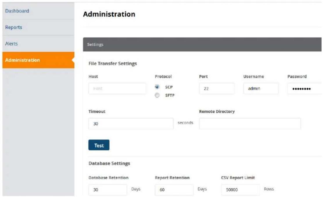
Support Information
• Insight database migration is supported.
- Configuration migration is not supported.
• Database retention default: 30 days
• Report retention default: 60 days
• CSV report limit: 50,000 rows
File Transfer Settings Configuration
You can specify the file transfer settings for uploading generated Insight reports to a FileStore. To configure the File Transfer settings:
- Navigate to the Administration page.
Figure 799: Specifying the Insight File Transfer Settings
File Transfer Settings
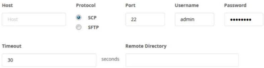
Test
- In the File Transfer Settings section, enter the appropriate values as described in Table 406.
- When finished, click Save.
Table 406: Insight File Transfer Parameters
| Parameter Action/Description | |
| Host 1. Specify the IP address | of the destination host FTP server. |
| Protocol 2. Specify the protocol | to be used to upload the generated reports to a FileStore.You can select from the following protocols:SCP (Session Control Protocol)SFTP (SSH File Transfer Protocol) |
| Port 3. Specify the destination | port number.The default destination port is 22. |
| Username/Password 4. Enter the username and password of the host FTP server. | |
| Timeout 5. Specify the timeout | value in seconds.The default value is 30 seconds. |
| Remote Directory | 6. Specify the location where the generated reports are to be copied.If the remote directory location is same as default root of FTP, you can leave this field blank.NOTE: To copy reports to a remote directory, you must enable the Reports >Create New Report >Enable remote copy option. |
Testing File Transfer Configuration
When you have configured the Insight file transfer settings, you can then test to see if file transfer is operational.
To test the Insight file transfer configuration:
- Review the File Transfer Settings to ensure they are correct.
- Click the Test button.
You see the message: File Transfer Settings testing in progress...
Then the following screen appears:
Figure 800: Successful File Transfer Test
File Transfer Settings
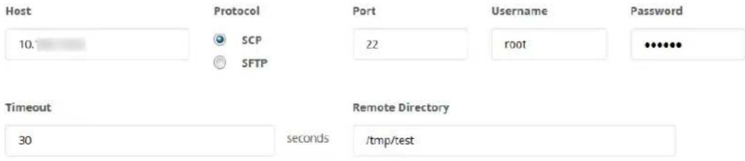

Test tgz file has been copied to 'test' folder
in remote directory
You are now ready to commence transferring Insight files to the FTP server as needed.
Database Settings Configuration
To configure the Insight database parameters:
- Navigate to the Administration page.
The Database Settings section is at the bottom of the Administration page.
Figure 801: Specifying the Insight Database Settings
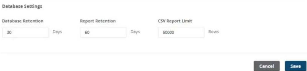
- In the Database Settings section, enter the appropriate values as described in Table 407.
- When finished, click Save.
Table 407: Insight Database Parameters
| Parameter Action/Description | |
| Database Retention 1. Specify the number of days to retain the database.The supported range is from 1 to 730 days. The default value is 30 days. | |
| Report Retention | 2. Specify the number of days to retain the generated reports.The supported range is from 1 to 365 days. The default value is 60 days. |
| CSV Report Limit | 3. Specify the number of rows for a CSV report.The supported range is from 1 to 50,000 rows. The default value is 50000 rows. |
Managing Insight Admin Privileges
This section provides the following information:
Overview
• Viewing the Default Insight Admin Privileges
• Defining Custom Insight Admin Privileges
• Insight UI Differences for Read-Only Users
Overview
W-ClearPass supports multilevel Insight administrators, each with a different level of administrative access Insight.
W-ClearPass provides a default Admin Privileges Read-only Administrator. The default sets of admin privilege cannot be modified.
Each of the Insight modules (Dashboard, Reports, Alerts, and Administration) can have three privilege levels no privileges:
- Read-only
- Read and Write
- Read, Write, and Delete
In the case of a user with no Insight admin privileges, the navigation panel on the left side of the Insig interface is not visible.
Viewing the Default Insight Admin Privileges
The settings for the default admin privileges cannot be modified.
To view the default Insight admin privileges defined in W-ClearPass:
- Navigate to Administration > Users and Privileges > Admin Privileges.
The Admin Privileges page opens.
Figure 802: Admin Privileges Page
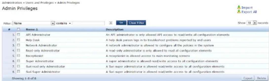
-
To view the Read-only admin privileges for Insight, select Read-only Administrator. The Edit Admin Privileges dialog opens.
-
Select the Insight tab.
The default Insight admin privileges for the Read-only Administrator are displayed.
Figure 803: Insight Read-Only Administrator Admin Privileges
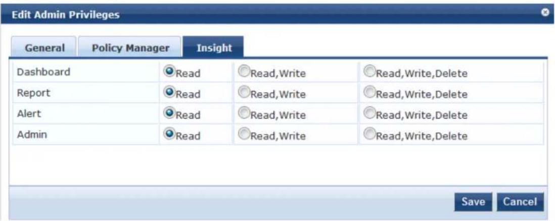
As shown in Figure 803, the default admin privileges for the Insight Read-only Administrator specifies Read-only access to all of the Insight modules—Dashboard, Reports, Alerts, and Administration.
Defining Custom Insight Admin Privileges
As described above, W-ClearPass provides a default Read-only Administrator. The default sets of admin privileges cannot be modified.
When a different set of admin privileges is needed (for example, if you require different admin privileges the Report module than the admin privileges defined for the other Insight modules), you must create a admin privileges administrator.
Insight privileges can be defined from two locations:
• Operator Profiles in W-ClearPass Guest
- Admin Privileges in W-ClearPass
To define custom admin privileges for Insight:
- Navigate to Administration > Users and Privileges > Admin Privileges.
The Admin Privileges page opens.
- Click the Add link.
The Add Admin Privileges dialog opens.
Figure 804: Add Admin Privileges Dialog: Basic Information Tab
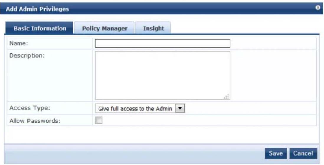
- Specify the parameters in the Basic Information tab as described in Table 408.
Table 408: Add Admin Privileges Parameters: Basic Information Tab
| Parameter Action/Description | |
| Name 1. Enter the name of the Admin Privileges administrator. | |
| Description 2. Provide a description of this new admin privileges administrator. | |
| Access Type 3. Select one of the following Access Types:Give full access to the AdminGive UI access to the AdminGive API access to the Admin | |
| Allow Passwords 4. Select this check box if you want to allow password access. |
Specifying Insight Admin Privileges
To specify the Insight admin privileges for the new administrator:
- When you complete the Basic Information parameters, select the Insight tab.
The Add Admin Privileges > Insight dialog opens.
Figure 805: Add Admin Privileges > Insight Dialog
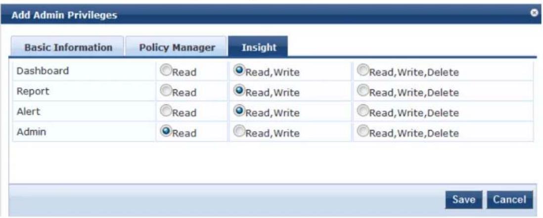
You must configure the admin privileges for Policy Manager also, otherwise the changes to the Insight admin privileges cannot be saved.
- Specify the desired admin privileges for each of the Insight modules, then click Save.
Insight UI Differences for Read-Only Users
When Insight is accessed by a user who has Read-only privileges for all four Insight modules (Dashboard Reports, Alerts, and Administration), that user is not allowed to create or delete reports.
As shown in Figure 806, when a Read-only administrator logs in to Insight, the Create New Report button is not visible.
Likewise, the Delete icon on the Configured Reports table is not visible for a Read-only administrator.
Figure 806: Create New Report Button Not Present for Read-Only User

Various action buttons, icons, and so on throughout the Insight user interface are shown only to users allowed to execute the actions provided by their admin privilege level.

Refer to the following sections to perform various tasks using the Command Line Interface (CLI):
- Cluster Commands on page 821
- Configure Commands on page 824
• Miscellaneous Commands on page 836
• Network Commands on page 830
• Service Commands on page 845
• Show Commands on page 847
• SSH Timed Account Lockout
• System Commands on page 856
Cluster Commands
The Policy Manager command line interface includes the following cluster commands:
- cluster drop-subscriber
- cluster list
- cluster make-publisher
- cluster make-subscriber
- cluster reset-database
- cluster set-cluster-passwd
- cluster sync-cluster-passwd
cluster drop-subscriber
Use the drop-subscriber command to remove a specific subscriber node from the cluster.
Syntax
cluster drop-subscriber [-f] [-i
Table 409 describes the required and optional parameters for the drop-subscriber command:
Table 409: Drop-Subscriber Command Parameters
| Parameter/Flag Action/Description | |
| -f Enter the -f parameter to force W-ClearPass to drop even the nodes that are down. | |
| -iSpecify the Management IP address of the node.If this IP address is not specified and the current node is a Subscriber, Policy Manager drops the current node. | |
| -s | Restricts resetting the database on the dropped node.By default, Policy Manager drops the current node—if it's a Subscriber—from the cluster. |
Example
The following example removes the IP address 192.xxx.1.1 from the cluster:
[appadmin]# cluster drop-subscriber -f -i 192.xxx.1.1 -s
cluster list
Use the cluster list command to list all the nodes in the cluster.
Syntax
cluster list
Example
The following example lists all the nodes in a cluster:
[appadmin]# cluster list
cluster make-publisher
Use the cluster make-publisher command to promote a specific subscriber node to be the publisher node in the same cluster.
When running this command, do not close the shell or interrupt the command execution.
Example
The following example promotes a subscriber node to publisher node status:
[appadmin]# cluster make-publisher
******************************************************************************************
* WARNING: Executing this command will promote the *
* current machine (which must be a subscriber in the *)
* cluster) to the cluster publisher. Do not close the *
* shell or interrupt this command execution. *
****************************************************************************************
Continue? [y|Y]: y
To continue the make-publisher operation, enter y.
cluster make-subscriber
Run the cluster make-subscriber command on a standalone Publisher to make the standalone node a Subscriber node and add it to the cluster.
Syntax
cluster make-subscriber -b -i
Table 410 describes the required and optional parameters for the make-subscriber command:

Table 410: Cluster Make-Subscriber Command Parameters
| Parameter/Flag Action/Description | |
| -b Generates a backup | of the publisher before you make it a subscriber in the event themake-subscriberprocess fails and you need to restore the Publisher. |
| -iSpecify | the Publisher's IP address. This field is mandatory. |
| -l Restores the local log | database after this operation. This field is optional. |
Example
The following example converts the node with IP address 192.xxx.1.1 to a subscriber node: [appadmin]# cluster make-subscriber -i 192.xxx.1.1 -l
cluster reset-database
Use the reset-database command to reset the local database and erase its configuration.
Running this command erases the Policy Manager configuration and resets the database to its default configuration—all the configured data will be lost.
When running this command, do not close the shell or interrupt the command execution.
Syntax
cluster reset-database
Example
The following example reset the database:
[appadmin]# cluster reset-database
****************************************************************************************
* WARNING: Running this command will erase the Policy Manager *
* configuration and leave the database with default *
* configuration. You will lose all the configured data. *
* Do not close the shell or interrupt this command *
* execution.
****************************************************************************************
Continue? [y|Y]: y
To continue the reset-database operation, enter y.
cluster set-cluster-passwd
Use the cluster set-cluster-passwd command to change the cluster password on all nodes in the cluster. You may only issue this command from the publisher node.
Setting the cluster password changes the appadmin password for all the nodes in the cluster

WARNING

NOTE

NOTE
Syntax
cluster set-cluster-passwd
Example
The following example changes the cluster password on publisher nodes:
[appadmin]# cluster set-cluster-passwd
cluster set-cluster-passwd
Continue? [y|n]: y
Enter Cluster Passwd: college.162
Re-enter Cluster Passwd: college.162
INFO - Password changed on local (publisher) node
Cluster password changed
cluster sync-cluster-passwd
Use the cluster sync-cluster-passwd command to synchronize the cluster (appadmin) password currently set on the publisher with all the subscriber nodes in the cluster.
Synchronizing the cluster password changes the appadmin password for all the nodes in the cluster

Syntax
cluster sync-cluster-passwd
Example
The following example synchronizes the cluster password:
[appadmin]# cluster sync-cluster-passwd
Continue? [y|n]: y
Enter Password: college.205
Re-enter Password: college.205
Configure Commands
The W-ClearPass Policy Manager command line interface includes the following configure commands:
- configure date
- configure dns
- configure fips-mode
- configure hostname
- configure ip
- configure ip6
- configure mtu
- configure timezone
configure date
Use the configure date command to specify the cluster's primary and secondary NTP (Network Time Protocol) servers, the key index, key value, encryption type, and optionally, the time zone for the Publish
node.
The Audit Viewer (Monitoring > Audit Viewer) tracks NTP configuration changes.
Syntax
configure date -p
The following table describes the parameters for the configure date command:
Table 411: Configure Date Command Parameters
| Flag/Parameter Action/Description | |
| -p <ntp_server1>-p <ntp_server2> | Specify the primary and secondary NTP server names or IP addresses.NOTE: You can specify a destination node with an IPv6 address enabled. |
| -a <key-index> | The Key Index (also referred to as the Key ID) is a number that specifies the index for key values.The key-index value can be from 1 to 65534 inclusive.Typically an NTP client and server have to trust the same key index and key value authentication to succeed. |
| -v <key-value> | The Key Value is a form of shared secret, which both the client and server use for authenticating NTP messages. The Key Value can be:Up to 20-character printable ASCII stringUp to 40-character hex valueWhen entering an ASCII string for the Key Value, note that it cannot contain the following characters:& (ampersand); (semicolon)`(grave accent)| (pipe)< (left angle bracket)> (right angle bracket)( (left parenthesis)) (right parenthesis)Finally, the Key Value ASCII string must start and end with one of the following characters:- (hyphen)' (apostrophe)" (quote) |
| -t <encryption-type> | Select one of the two options for Encryption Type:SHASHA1NOTE: In FIPS mode, SHA is not a supported encryption type. |
| -z <timezone> | Specify the time zone on the Publisher node.To view the list of supported time zones, enter show all-timezones. This field is opt |
Example 1
The following example configures the key-index, key-value, and encryption type for the primary and secondary NTP servers:
[appadmin]# configure date -p ntp1.cppm.main -a 24 -v cp1234567890 -t SHA -s ntp2.cppm.main -a 16 -v cp53.56 -t SHA1
Example 2
The following example synchronizes with the primary NTP server. Note that in this example, the key-value is a hex code. Using a hex code for the key-value is supported only in the CLI, not in the user interface.
[appadmin]# configure date -p ntp1.cppm.main -a 96 -v 6bf60ca1876b57248311aa07c7783d391be95d6c -t SHA1
configure dns
Use the configure dns command to configure DNS servers. You must specify a minimum of one DNS server; you can specify a maximum of three DNS servers.
Syntax
configure dns
Example 1: DNS Server
The following example configures a DNS server:
[appadmin]# configure dns 192.168.xx.1
Example 2: Primary and Secondary DNS Servers
The following example configures the primary and secondary DNS servers. You can configure IPv6 address described in this example.
[appadmin]# configure dns 192.168.xx.1 2001:4860:4860::8888
Example 3: Primary, Secondary, and Tertiary DNS Servers
The following example configures primary, secondary, and tertiary DNS servers:
[appadmin]# configure dns 192.168.xx.1 2001:4860:4860::8888 192.168.xx.2
configure fips-mode
Use the configure fips-mode command to enable or disable FIPS (Federal Information Processing Standard) mode.
Running this command erases the W-ClearPass Policy Manager configuration settings and returns the database to the default configuration. All configured data will be lost. This command also shuts down all running applications ar reboots the system.
Syntax
configure fips-mode [0|1]
The following table describes the parameters for the configure fips-mode command:

Table 412: Configure fips-mode Command Parameters
| Flag/Parameter Action/Description | |
| 0 To disable FIPS mode, enter 0.Read the warning message carefully before enabling or disabling FIPS mode. | |
| 1 To enable FIPS mode, enter 1. |
Example 1
The following example disables FIPS mode:
[appadmin]# configure fips-mode 0
- *
- WARNING: Running this command will erase the Policy Manager *
- configuration and leave the database with default *
- configuration. You will lose all the configured data. *
- *
- This command will also shutdown all applications and reboot *
- the system. *
- *
- Do not close the shell or interrupt this command execution. *
- *
Continue? [y|n]: y
Clicking y in this example disables FIPS mode.
configure hostname
Use the configure hostname command to configure the hostname.
Syntax
configure hostname
Example
The following example configures a hostname:
[appadmin]# configure hostname sun.us.dellnetworks.com
configure ip
Use the configure ip command to configure the IPv4 address of the management interface or the data interface, netmask, and gateway address.
Syntax
[appadmin]# configure ip
The following table describes the parameters used in the configure ip command:
Table 413: Configure IP Command Parameters
| Flag/Parameter Action/Description | |
| ip | Specify the network interface type: management port interface or data point interface.specifies the IPv4 address of the host. |
| netmask Specify the netmask for the IP address. | |
| gateway Specify the IP address for the network gateway. | |
Example
The following example configures the IP address for the data interface, the netmask for that address, an gateway address:
[appadmin]# configure ip data 192.168.xx.12 netmask 255.255.255.0 gateway 192.168.xx.1
configure ip6
Use the configure ip6 command to configure the IPv6 address, netmask, and gateway address of the host.
Syntax
configure ip6
configure ip6
The following table describes the parameters used in the ip6 command:
Table 414: Configure ip6 Command Parameters
| Flag/Parameter Action/Description | |
| ip6 | Specifies the network interface type: management interface or data interface. |
| netmask | Specifies the netmask.For example, ffff:ffff:ffff:0000:0000:0000:0000. |
| gateway | Specifies the gateway address.For example, fe90:0000:0000:0000:020c:29ff:fe7e:d3a2. |
Example
The following example configures the IPv6 management interface, netmask, and gateway address:
[appadmin]# configure ip6 mgmt fe90:0000:0000:0000:020c:29ff:fe7e:d3e1 netmask
ffff:ffff:ffff:ffff:0000:0000:0000:0000 gateway fe90:0000:0000:0000:020c:29ff:fe7e:d3a1
configure mtu
Use the configure mtu command to set the MTU (Maximum Transmission Unit) for the management and data port interfaces.

Running this command might cause the W-ClearPass server to lose network connectivity.
Syntax
configure mtu
The following table describes the configure mtu command parameters:
Table 415: Configure mtu Command Parameters
| Flag/Parameter Action/Description | |
| mtu | Specify the network interface types: management port interface or data port interface. |
| Specify the MTU value in bytes. The default value is 1500 bytes. | |
Example 1
The following example configures the MTU management interface:
[appadmin] # configure mtu mgmt 1498
******************************************************************************************
* *
* WARNING: Running this command might cause system *
* to lose network connectivity and may require relogin.*
* *
******************************************************************************************
Continue? [y|Y]: y
INFO: Restarting network services
INFO: Successfully applied MTU settings
Example 2
The following example configures the MTU data port value:
[appadmin]# configure mtu data 1498
******************************************************************************************
* *
* WARNING: Running this command might cause system *
* to lose network connectivity and may require relogin.*
* *
******************************************************************************************
Continue? [y|Y]: y
INFO: Restarting network services
INFO: Successfully applied MTU settings
Example 3
Use the show ip command to display the settings of the MTU management and data port interfaces:
[appadmin]# show ip
Device Type : Management Port
IPv4 Address : 10.2.xx.86
Subnet Mask : 255.255.255.0
Gateway : 10.2.xx.1
IPv6 Address : 2607:f0d0:1002:0011:0000:0000:0000:0002
Subnet Mask : ffff:ffff:ffff:ffff:0000:0000:0000:0000
Gateway : 2607:f0d0:1002:0011:0000:0000:0000:0001
Hardware Address : 00:0C:29:70:27:40
MTU : 1499
Device Type : Data Port
IPv4 Address :
Subnet Mask :
Gateway :
IPv6 Address : fe80:0000:0000:0000:020c:29ff:fe70:274a
Subnet Mask : ffff:ffff:ffff:ffff:0000:0000:0000:0000
Gateway : fe80:0000:0000:0000:020c:29ff:fe70:2741
Hardware Address : 00:0C:29:70:27:4A
MTU : 1498
DNS Information
Primary DNS : 10.2.xx.3
Secondary DNS : 10.1.xx.50
Tertiary DNS : 10.1.xx.200
configure timezone
Use the configure timezone command to interactively configure the time zone.
Syntax
configure timezone
Example
The following example configures the time zone interactively:
[appadmin]# configure timezone
configure timezone
******************************************************************************************
* WARNING: When the command is completed Policy Manager services *
* are restarted to reflect the changes.
****************************************************************************************
Continue? [y|Y]: y
Network Commands
The W-ClearPass Policy Manager command line interface includes the following network commands:
- network ip6
- network ip
- nslookup
• Network Commands on page 830 - network ping6
- network reset
• network traceroute6
• network traceroute
network ip6
Use the network ip6 command to add, delete, or list custom routes to the data or management interface routing table in IPv6 networks.
Syntax: network ip6 add
network ip6 add
The following table describes the required and optional parameters for the network ip6 command:
Table 416: Network IP6 Add Command Parameters
| Flag/Parameter Description | |
| Management or the data interface. | |
| -i Specifies the ID of the network IP rule. If this ID is not specified, the system generates an ID automatically.NOTE: This ID determines the priority in the ordered list of rules in the routing table | |
| -s Specifies the source interface IPv6 address or netmask from where the network IPv6 rule is specified. For example, fe82::20c:29ff:fe7e:d3e1. A valid IPv6 address or a netmask or 0/0 values are allowed. This parameter is optional. | |
| -d Specifies the destination interface IPv6 address or netmask where the network IPv6 rule is specified. A valid IPv6 address or a netmask or 0/0 values are allowed. This parameter is optional. | |
| -g Specifies the via or gateway IPv6 address through which the network traffic should flow. A valid IPv6 address is allowed. This parameter is optional. | |
Example: Adding an IPv6 Custom Route
You can use an IPv6 address when adding a custom route.
The following example adds a custom route:
[appadmin]# network ip6 add data -s fe82::20c:29ff:fe7e:d3e1/d3e24
Syntax: network ip6 del
This command deletes an IPv6 custom route.
network ip6 del <-i
Syntax: network ip6 list
This command lists all custom routing rules.
network ip6 list
Example: Listing All IPv6 Custom Routing Rules
The following example lists all custom routing rules:
[appadmin]# network ip6 list
IP Rule Information
0: from all lookup local
13000: from all to fe82::20c:99ff:fe7e:d3e1 lookup mgmt
13001: from all to fe82::20c:99ff:fe7e:d3e4 lookup mgmt
13002: from all to fe82::20c:99ff:fe7e:d3e7 lookup mgmt
13003: from all to fe82::20c:99ff:fe7e:d3e8 lookup mgmt
13004: from all to fe82::20c:99ff:fe7e:d3e9 lookup mgmt
13005: from all to fe82::20c:99ff:fe7e:d3ea lookup static
32766: from all lookup main
Syntax: network ip6 reset
network ip6 reset
This command resets the routing table to the factory default settings and all custom routes are removed
network ip
Use the network ip command to add, delete, or list custom routes to the data or management interface routing table.
Syntax: network ip add
network ip add <mgmt|data|greN|vlanN> [-i <id>] <[-s <SrcAddr>] [-d <DestAddr>] [-g <ViaAddr>]
The following table describes the required and optional parameters for the network ip add command:
Table 417: Network IP Add Command Parameters
| Flag/Parameter Description | |
| Configures the management interface, data interface, the name of the GRE tunnel, or the VLAN number.: N specifies the GRE tunnel number ranging from 1,2,3...N.: N specifies the VLAN number. | |
| -i Specifies the ID of the network IP rule. If this ID is not specified, the system generates an ID automatically.NOTE: This ID determines the priority in the ordered list of rules in the routing table | |
| -s | Specifies the IP address or network. For example, 192.168.xx.0/24 or 0/0 (for all traffic) of traffic originator. You must specify only one source IP address. This parameter is optional. |
| -d | Specifies the destination IP address or network. For example, 192.168.xx.0/24 or 0/0 (for all traffic). You must specify only one destination IP address. This parameter is optional. |
| -g | Specifies the via or gateway IP address through which the network traffic should flow. A valid IP address is allowed. This parameter is optional. |
Syntax: network ip del
network ip del <-i
The following table describes the parameter for the network ip del command:
Table 418: Network IP Del Command Parameters
| Flag/Parameter Description | |
| -i <id> Specifies the ID of the rule to delete. |
Syntax: network ip list
network ip list
This command lists all routing rules.
Example: Adding a Custom Route
The following example adds a custom route:
[appadmin]# network ip add data -s 192.168.xx.0/24
Example: Listing All Custom Routes
The following example lists all custom routes:
[appadmin]# network ip list
IP Rule Information
0: from all lookup local
10020: from all to 10.xx.4.0/24 lookup mgmt
10040: from 10.xx.4.200 lookup mgmt
10060: from 10.xx.5.200 lookup data
32766: from all lookup main
32767: from all lookup default
Syntax: network ip reset
network ip reset
This command resets the routing table to the factory default settings. All custom routes are removed.
nslookup
Use the network nslookup command to get the IP address of the host using DNS.
Syntax: network nslookup
network nslookup -q
The following table describes the required and optional parameters for the nslookup command:
Table 419: Network Nslookup Command Parameters
| Flag/Parameter Description | |
| Specifies the type of DNS record. The record types available are: A AAAA CNAME PTR SRV | |
| Specifies the host or domain name to be queried. | |
Example: Obtaining Address of Host or Domain
The following examples obtain the IPv4 and IPv6 addresses of the host or domain using DNS:
[appadmin]# nslookup sun.us.dellnetworks.com
[appadmin]# network nslookup 2001:4860:4860::8888
Example: Querying for SRV Records
The following example queries a host or domain for SRV records:
[appadmin]# nslookup -q SRV dellnetworks.com
Syntax
Use the AAAA flag with the -q option to perform network nslookup with IPv6 destinations.
nslookup -q AAAA
Example: Nslookup for IPv6 Address
The following example performs network nslookup for the destination with an IPv6 address:
[appadmin]# network nslookup 2001::93
Server: 2001::94
Address: 2001::94#53
Address: 2001::94#53
ipv6test-n1.cppmipv6.com has AAAA address 2001::93
network ping6
Use the network ping6 command to test the reachability of the network host.
Syntax: network ping6
network ping6 [-i
The following table describes the required and optional parameters for the network ping6 command:
Table 420: Network Ping6 Command Parameters
| Flag/Parameter Description | |
| -iSpecifies the originating IPv6 address for the ping. This field is optional. | |
| -t | Use this parameter to ping indefinitely. This field is optional. |
| Specifies the host to be pinged. | |
Example
The following example pings an IPv6 network host to test its reachability:
[appadmin]# network ping6 -i fe82::20c:29ff:fe7e:d3e1 -t sun.us.
dellnetworks
.com
network ping
Use the network ping command to test the reachability of the network host.
Syntax: network ping
network ping [-i
The following table describes the required and optional parameters for the network ping command:
Table 421: Network Ping Command Parameters
| Flag/Parameter Description | |
| -iSpecifies the originating IP address for the ping. This field is optional. | |
| -t Use this parameter to ping indefinitely. This field is optional. | |
Example: Testing Reachability
The following example pings a network host to test the reachability:
[appadmin]# network ping -i 192.168.xx.10 -t sun.us.dellnetworks.com
network reset
Use the network reset command to reset the network data and management ports. You can use this command to reset both IPv4 and IPv6 addresses.
Syntax: network reset
network reset
The following table describes the required and optional parameters for the network reset command:
Table 422: Network Reset Command Parameters
| Flag/Parameter | Description |
| data [v4 | v6] | Specifies the name of network data port to reset, as well as whether it is an IPv4 or IPv6 address. This parameter is mandatory. |
| mgmt | Specifies the name of network management port to reset. |
Example
The following example resets the IPv6 network data port:
[appadmin]# network reset data v6
network traceroute6
Use the network traceroute6 command to print the route taken to reach the IPv6 network host.
Syntax: network traceroute6
network traceroute6
The following table describes the required and optional parameters for the network traceroute6 command:
Table 423: Network Traceroute6 Command Parameters
| Flag/Parameter Description | |
| Specifies the name of network host. You can specify the host with an IPv6 address. | |
Example
The following example prints the route taken to reach the network host:
[appadmin]# network traceroute6 sun.us.dellnetworks.com
network traceroute
Use the network traceroute command to print the route taken to reach the network host.
Syntax: network traceroute
network traceroute
The following table describes the required parameter for the network traceroute command:
Table 424: Network Traceroute Command Parameters
| Flag/Parameter Description | |
| Specifies the name of the network host. |
Example
The following example prints the route taken to reach the network host:
[appadmin]# network traceroute sun.us.dellnetworks.com
Miscellaneous Commands
The Policy Manager command line interface includes the following miscellaneous commands:
• ad auth on page 837
• ad netjoin on page 837
• ad netleave on page 838
- ad passwd-server
• ad testjoin on page 839
- alias on page 839
- backup on page 840
- dump certchain on page 841
- dump logs on page 841
- dump servercert on page 842
- exit on page 842
• help on page 842
• krb auth on page 843
• krb list on page 843 - Idapsearch on page 843
- quit on page 844
- restore on page 844
ad auth
Use the ad auth command to authenticate the user against Active Directory.
Syntax
ad auth
The following table describes the parameters for the ad auth command:
Table 425: AD Auth Command Parameter
| Flag/Parameter Description | |
| Specifies the username of the authenticating user. This is a mandatory parameter. | |
| Specifies the domain name. This field is optional. | |
Example
The following example authenticates the user against Active Directory:
[appadmin]# ad auth jbrown -n cppm.sanfran1
ad netjoin
Use the ad netjoin command to join the host to the domain.
Syntax
ad netjoin
The following table describes the parameters for the ad netjoin command:
Table 426: AD Netjoin Command Parameters
| Parameter Action/Description | |
| Specify the complete Fully Qualified Domain Name (FQDN) of the domain controller, including its hostname.For example, if atlas.org is the Domain FQDN and DC01.atlas.org is one of its domain controllers, then this argument would be correctly expressed as DC01.atlas.orgThis field is mandatory. | |
| [domain NetBIOS name] Specify the NetBIOS name of the domain (optional argument).You can specify this argument if the derived NetBIOS name is different from actual name. This is an optional argument. | |
| [domain REALM name] You can specify this argument if the derived REALM is different from the actual.This is an optional argument. | |
| [ou=] If the computer account must be created in a different OU, this argument specifies the Object Container .For example 'ou=Domain Computer'OR'ou=Domain Computer+Linux Hosts'.Note the usage of the separator '+' to specify the OU hierarchy. | |
Example
The following example joins the host to the domain:
[appadmin]# ad netjoin DC01.atlas.org.dellnetworks.com
ad netleave
Use the ad netleave command to remove the host from the domain.
Syntax
ad netleave
Table 427: AD Netleave Command Parameters
| Flag/Parameter Description | |
| Specifies the host to be joined to the domain. This field is mandatory. | |
| -f | Forces the removal of Active Directory domain membership even if the ope fails. |
Example
The following example removes the host from the domain:
[appadmin]# ad netleave balsamcollege.edu -f
ad passwd-server
Use the ad passwd-server command to do the following tasks:
- Set the password servers.
• List the configured password servers.
- Reset the password servers.
Syntax
ad passwd-server
Table 428: AD passwd-server Command Parameters
| Flag/Parameter Description | |
| set- n- s [Server2 Server3 Server4 ...] | Sets the password servers.The -n parameter specifies the domain name.The -s parameter specifies one or more password server names. |
| list -n Lists the configured password servers. | |
| reset -n Resets the password servers. | |
Example
The following example sets the configured password servers:
[appadmin]# ad passwd-server set -n balsamcollege.edu -s cppm.campus1
ad testjoin
Use the ad testjoin command to test if the ad netjoin command succeeded. This command also tests whether Policy Manager is a member of the Active Directory domain.
Syntax
ad testjoin
Table 429: AD Netjoin Command Parameter
| Flag/Parameter Description | |
| Specifies the host to be joined to the domain. This field is mandatory. |
Example
The following example tests if the ad testjoin command succeeded:
[appadmin]# ad testjoin balsamcollege.edu
alias
Use the alias command to create or remove aliases.
Syntax
alias
The following table describes the parameters for the alias command:
Table 430: Alias Command Parameters
| Flag/Parameter Description | |
| Setsas the alias for. | |
| = Removes the association. | |
Example 1
This example set the alias "sh" for the show command:
[appadmin]# alias sh=show
Example 2
This example removes the alias "sh":
[appadmin]# alias sh=
backup
Use the backup command to create a backup of Policy Manager configuration data. If no arguments are entered, the system automatically generates a filename and backs up the configuration to this file.
Syntax
backup [-f
The following table describes the parameters for the backup command:
Table 431: Backup Command Parameters
| Flag/Parameter Description | |
| [-f] Specifies the | backup target. If not specified, Policy Manager automatically generates a filename. This field is optional. |
| -c Backs up W-ClearPass Policy Manager configuration data. | |
| -l | Backs up W-ClearPass Policy Manager session log data. |
| -r | Backs up Insight data. |
| -P | Does not backup password fields from the configuration database. This field is optional. |
| -w | Backs up only the most recent records from the log database (the last one week). |
Example
[appadmin]# backup -f PolicyManager-data.tar.gz Continue? [y|Y]: y
dump certchain
Use the dump certchain command to remove the certificate chain of any SSL-secured server.
Syntax
dump certchain
The following table describes the parameter for the dump certchain command:
Table 432: Dump Certchain Command Parameter
| Flag/Parameter Description | |
| Specifies the hostname and SSL port number. | |
Example 1
The following example dumps the certificate chain of an SSL-secured server:
[appadmin]# dump certchain ldap.acme.com:636
dump logs
Use the dump logs command to remove Policy Manager application log files.
Syntax
dump logs -f
The following table describes the parameters for the dump logs command:
Table 433: Dump Logs Command Parameters
| Flag/Parameter Description | |
| -fSpecifies the target for concatenated logs. | |
| -s yyyy-mm-dd | Specifies the start date range. The default value is today's date. This field is optional. |
| -e yyyy-mm-dd | Specifies the end date range. The default value is today's date. This field is optional. |
| -n | Specifies the duration in days (from today). This field is optional. |
| -t | Specifies the type of log to collect. This field is optional. |
| -h | Specifies the print help for available log types. |
Example 1
The following example dumps Policy Manager application log files:
[appadmin]# dump logs -f tips-system-logs.tgz -s 2007-10-06 -e 2007-10-17 -t SystemLogs
Example 2
The following example prints help for the available log types:
[appadmin]# dump logs -h
dump servercert
Use the dump servercert command to remove the server certificate of an SSL-secured server.
Syntax
dump servercert
The following table describes the parameter for the dump servercert command:
Table 434: Dump Servercert Command Parameter
| Flag/Parameter Description | |
| Specifies the hostname and SSL port number. | |
Example
The following example removes the server certificate of the specified SSL-secured server:
[appadmin]# dump servercert ldap.acme.com:636
exit
Use the exit command to exit the shell.
Syntax
exit
Example
The following example exits the shell:
[appadmin]# exit
help
Use the help command to display the list of supported commands:
Syntax
help
Example
The following example displays the list of supported commands:
[appadmin]# help
help
alias Create aliases
backup Backup Policy Manager data
cluster Policy Manager cluster related commands
configure Configure the system parameters
dump Dump Policy Manager information
exit Exit the shell
help Display the list of supported commands
netjoin Join host to the domain
netleave Remove host from the domain
network Network troubleshooting commands
quit Exit the shell
service Control Policy Manager services
show Show configuration details
system System commands
krb auth
User the krb auth command to perform a Kerberos authentication against a Kerberos server (such as Microsoft Active Directory).
Syntax
krb auth user@domain
The following table describes the parameter for the krb auth command:
Table 435: Kerberos Authentication Command Parameter
| Flag/Parameter Description | |
| Specifies the username and domain. | |
Example
The following example performs a kerberos authentication against a kerberos server:
[appadmin]# krb auth mike@corp-ad.acme.com
krb list
Use the krb list command to list the cached Kerberos tickets.
Syntax
krb list
Example
The following example lists the cached Kerberos tickets:
[appadmin]# krb list
Idapsearch
Use the Linux Idapsearch command to find objects in an LDAP directory. Note that only the Policy Manager-specific command line arguments are listed. For other command line arguments, refer to Idapsearch man pages on the Internet.
Syntax
ldapsearch -B user@hostname
The following table describes the parameters for the Idapsearch command:
Table 436: LDAP Search Command Parameter
| Flag/Parameter Description | |
| -B Finds the bind DN (Distinguished Name) of the LDAP directory. | |
| Specifies the username and the full qualified domain name of the host. | |
Example
The following example finds objects in an LDAP directory:
[appadmin]# ldapsearch -B admin@corp-ad.acme.com
quit
Use the quit command to exit the shell.
Syntax
quit
Example
The following command quits the shell:
[appadmin]# quit
restore
Use the restore command to restore Policy Manager configuration data from the backup file.
Syntax 1
restore user@hostname:/
Syntax 2
restore http://hostname/
Syntax 3
restore
The following table describes the parameters for the restore command:
Table 437: Restore Command Parameters
| Flag/Parameter Description | |
| user@hostname:/ | Specifies the filepath of the the restore source. |
| http://hostname/ | |
| -b Does not backup the current configuration data before the restore operation starts. | |
| -c Restores W-ClearPass Policy Manager configuration data. | |
| -l If it exists in the backup file, restores the W-ClearPass Policy Manager log database. This field is optional. | |
| -i Ignores version mismatch errors and attempts data migration. This field is | |
| optional. | |
| -n Retains local node configuration data, such as certificates, after the restore operation (default). | |
| -N Does not retain local node configuration data after the restore operation. | |
| -r Restores Insight data if it exists in the backup. | |
| -s Restores cluster server/node entries from the backup file. Node entries are in a disabled state upon restore. This field is optional. | |
Example
The following example restores Policy Manager configuration data from the backup file:
[appadmin]# restore user@hostname:/tmp/cppml-backup.tgz -l -i -c -s
Service Commands
The Policy Manager CLI includes the following service
- service list
- service restart
- service start
- service status
- service stop
service
Use the service
Syntax
service
Table 438: Service Action Command Parameters
| Service Parameter Description | |
| action 1. Choose an action: | listrestartstartstatusstop |
| service-name 2. Choose a service: | cpass-policy-servercpass-tacacs-servercpass-radius-servercpass-admin-servercpass-dbwrite-servercpass-dbcn-servercpass-repl-servercpass-system-auxiliary-servercpass-sysmon-servercpass-domain-serverAirgroup-notifyfias_servercpass-ipsec-servicecpass-vip-servicecpass-async-netdcpass-statsd-servercpass-igssyslog-servercpass-igslogger-servercpass-igslogrepo-servercpass-carbon-servercpass-multi-master-cache-server |
Example
[appadmin]# service list all
Policy server [ cpass-policy-server ]
Admin UI service [ cpass-admin-server ]
System auxiliary services [ cpass-system-auxiliary-server ]
Radius server [ cpass-radius-server ]
Tacacs server [ cpass-tacacs-server ]
Async DB write service [ cpass-dbwrite-server ]
DB change notification server [ cpass-dbcn-server ]
DB replication service [ cpass-repl-server ]

System monitor service [ cpass-sysmon-server ]
Async network services [ cpass-async-netd ]
Multi-master cache [ cpass-multi-master-cache-server ]
Virtual IP service [ cpass-vip-service ]
Stats collection service [ cpass-statsd-server ]

Stats aggregation service [ cpass-carbon-server ]
ClearPass IPsec service [ cpass-ipsec-service ]
AirGroup notification service [ airgroup-notify ]
Micros Fidelio FIAS [ fias_server ]
Ingress logger service [ cpass-igslogger-server ]
Ingress syslog service [ cpass-igssyslog-server ]
Show Commands
The Policy Manager command line interface includes the following show commands:
• show all-timezones
• show date
• show dns
• show domain
• show fipsmode
• show fipsmode
• show hostname
• show ip
• show license
• show ntp
• show sysinfo
• show timezone
• show version
show all-timezones
Use the show all-timezones command to view all available time zones.
Syntax
show all-timezones
Example
The following displays an example of the show all-timezones command output:
[appadmin]# show all-timezones
America/Aruba
America/Barbados
America/Belem
America/Belize
[More]
show date
Use the show date command to view the system date, time, and time zone information.
Syntax
show date
Example
The following displays an example of the show date command output:
[appadmin]# show date
Wed Jan 27 14:33:39 UTC 2016
show dns
Use the show dns command to view DNS (Domain Name System) servers.
Syntax
show dns
Example
The following example of show dns command output displays the DNS servers configured for the current W-ClearPass server:
[appadmin]# show dns
DNS Information
Primary DNS : 192.xxx.5.3
Secondary DNS :
Tertiary DNS :
show domain
Use the show domain command to view the Active Directory Domain controller information.
The show domain command is operational only when the current W-ClearPass server is joined to an Active Directory domain.
Syntax
show domain
Example
The following displays an example of the show domain command output:
[appadmin]# show domain
Domain Information
Domain Name : COLLEGE152.COM
Domain NETBIOS Name : COLLEGE152
Domain Server IP Address : 10.xx.110
Domain Server Name : balsam.collegel52.com
Domain Status : online

show fipsmode
Use the show fipsmode command to find whether FIPS (Federal Information Processing Standard) mode is enabled or disabled.
Example
The following example shows that FIPS mode is enabled:
[appadmin]# show fipsmode
FIPS Mode: Enabled
show hostname
Use the show hostname command to view the hostname of the current W-ClearPass server.
Syntax
show hostname
Example
The following displays an example of the show hostname command:
[appadmin]# show hostname
cppm.chicago.1
show ip
Use the show ip command to view the IPv4, IPv6, and DNS information of the host.
Syntax
show ip
Example
The following example of the show ip command displays the IPv4, IPv6, and DNS information of the host:
[appadmin]# show ip
Device Type : Management Port
IPv4 Address : 10.2.xx.86
Subnet Mask : 255.255.255.0
Gateway : 10.2.xx.1
IPv6 Address : 2607:f0d0:1002:0011:0000:0000:0000:0002
Subnet Mask : ffff:ffff:ffff:ffff:0000:0000:0000:0000
Gateway : 2607:f0d0:1002:0011:0000:0000:0000:0001
Hardware Address : 00:0C:29:70:27:40
MTU : 1499
Device Type : Data Port
IPv4 Address :
Subnet Mask :
Gateway :
IPv6 Address : fe80:0000:0000:0000:020c:29ff:fe70:274a
Subnet Mask : ffff:ffff:ffff:ffff:0000:0000:0000:0000
Gateway : fe80:0000:0000:0000:020c:29ff:fe70:2741
Hardware Address : 00:0C:29:70:27:4A
MTU : 1498
DNS Information
Primary DNS : 10.2.xx.30
Secondary DNS : 10.1.xx.50
Tertiary DNS : 10.1.xx.200
show license
Use the show license command to view the Policy Manager license information.
Syntax
show license
Example
The following displays an example of the show license command output:
[appadmin]# show license
Application : PolicyManager
License key : VKQO-MW62AB-VMVF-B7GNJX-OHUABC-IAAM-RTQUPQ-WODIFNJI-CD7N-I1325A
License key type : Permanent
License added on : 2016-01-11 10:16:38
Validity :
Issued for : 5000 users
Customer id : JCC
Licensed features :
Application : PolicyManager
License key : VKQO-MW62AB-VMVF-B7GNJX-OHUABC-IAAM-RTQUPQ-WODIFNJI-CD7N-I1325A
License key type : Permanent
License added on : 2016-01-11 10:16:38
Validity :
Issued for : 5000 users
Customer id : JCC
Licensed features :
show ntp
Use the show ntp command to view the IP addresses of the primary and secondary Network Time Protocol (NTP) servers configured for the current W-ClearPass server.
Syntax
show ntp
Example
The following displays an example of the show ntp command output:
[appadmin]# show ntp
NTP Server Information
Primary NTP : 10.xx.x.1
Secondary NTP :
show sysinfo
Use the show sysinfo command to view the node uptime, disk utilization, and memory utilization information:
Syntax
show sysinfo
Example
The following displays an example of the show sysinfo command output:
[appadmin]# show sysinfo
System Uptime : 1 day, 23:29:15.510000
Disk Utilization
Total : 115.48 GB
Free : 5.42 GB (6%)
Memory Utilization
Total : 4.00 GB
Free : 1.36 GB (36%)
show timezone
Use the show timezone command to view the current system time zone.
Syntax
show timezone
Example
The following displays an example of the show timezone command output:
[appadmin]# show timezone
Timezone is set to 'Asia/Kolkata'
show version
Use the show version command to view the Policy Manager software version and the hardware model.
Syntax
show version
Example
The following displays an example of the show version command output:
[appadmin]# show version
Policy Manager software version : 6.6(4).6649
Policy Manager model number : ET-5010
SSH Timed Account Lockout
This section provides the following information:
- Introduction
• SSH Account Lockout Configuration
• SSH Account Lockout Alerts
• SSH Account Lockout Behavior
Introduction
The SSH Timed Account Lockout feature provides an administrator with the ability to configure the number of successive unsuccessful authentication attempts for administrators attempting to authenticate remotely.
When the defined number of unsuccessful authentication attempts has occurred, the CLI account is locke administrators cannot log in to the system via the CLI until one of the following conditions are met:
- Prevent the offending remote administrator from successfully authenticating until an action is taken by a local administrator.
- Prevent the offending remote administrator from successfully authenticating until time period defined by the administrator has elapsed.
Node-Specific
This feature is node-specific. In a cluster with multiple nodes, SSH timed account lockout must be config on each node in the cluster.

The cluster reset-database command does not impact this feature.
Account Lockout Persistence
The SSH timed account lockout feature configuration persists across reboots, updates and upgrades.
■ The account lock status persists across reboots.
SSH Account Lockout Configuration
The SSH Timed Lockout options are exposed as a part of the ssh command set.
Figure 807: SSH Command Set
[appadmin@123]# ssh lockout SSH lockout configuration options unlock Unlock the SSH locked out account
SSH Lockout
The ssh lockout command set provides ability to configure SSH lockout configuration options. This command exposes three options :
count
duration
- reset
Figure 808: SSH Lockout Command Set
[appadmin@123]# ssh lockout
Usage:
count Lockout attempts
duration Lockout duration
reset Reset SSH lockout configuration
SSH Lockout Count
Sets the maximum number of failed login attempts before the account is locked out. The default is 5.
Figure 809: SSH Lockout Count Command
[appadmin@123]# ssh lockout count
Usage:
ssh lockout count <N>
Where
N -- Maximum failed SSH password login attempts prior to account lockout. Allowed values are 1-1000. If ssh lockout duration is non-zero, this value (when not configured) defaults to 5.
[appadmin@123]# ssh lockout count 3
INFO: SSH lockout details updated to - Lockout count = 3, Unlock time = 900 secs
Syntax
ssh lockout count <N>
Example
ssh lockout count 3
SSH Lockout Duration
Sets the amount of time in minutes that the account will remain locked after the number of SSH passw login attempts exceeds the SSH lockout count.
Figure 810: SSH Lockout Duration Command
[appadmin@123]# ssh lockout duration
Usage:
ssh lockout duration <N mins>
Where
N -- Amount of time (in mins) the account will remain locked after the maximum failed SSH password login attempts. Allowed values are 1-10080. If ssh lockout count is non-zero, this value (when not configured) defaults to 15.
[appadmin@123]# ssh lockout duration 3
INFO: SSH lockout details updated to - Lockout count = 3, Unlock time = 180 secs
[appadmin@123]#
Syntax
ssh lockout duration <N minutes>
Example
ssh lockout duration 3
SSH Lockout Reset
Resets the SSH lockout count and duration to factory defaults and disables this feature.
The SSH timed account lockout feature is disabled by default.

Figure 811: SSH Lockout Reset Command
[appadmin@123]# ssh lockout reset
INFO: SSH lockout reset for the user appadmin
SSH Unlock
Unlocks any SSH locked accounts.
When the account is locked, you can perform this operation by logging into the system via the console a host that is enabled for SSH public key authentication with W-ClearPass.
Figure 812: SSH Unlock Command
[appadmin@123]# ssh unlock
INFO: Unlocked SSH lockout for the user appadmin
Show SSH
Shows the SSH lockout configuration settings and the active SSH client sessions.
Figure 813: Show SSH Command
![[appadmin@123]# show ssh ------------------------ SSH lockout details ------------------------ SSH lockout count : 7 attempts SSH lockout duration : 900 secs ------------------------ SSH sessions Client IP Address = 10.2.51.216 : Session Count = 3 Client IP Address = 10.6.132.117 : Session Count = 2 Client IP Address = 10.2.50.158 : Session Count = 1](/content/2026/05/842116/images/10403fb6f42f83ca7000e91bf1c377cd918222ead2c80cc443a0f047b00084af.jpg)
SSH Account Lockout Alerts
Alerts for SSH lockout events are logged in to the Event Viewer when any of the following conditions are present:
■ SSH lockout configurations are performed
■ Account is locked
■ Account is unlocked
■ Failed SSH login attempts
SSH Account Lockout Behavior
The SSH account lockout feature is disabled by default.
- To enable SSH account lockout:
■ Perform the ssh lockout count or ssh lockout duration configuration options.
-
To disable the feature, perform ssh lockout reset.
-
If the SSH account lockout feature is configured with failed attempts=3 and unlock time = 5 minutes:
-
CLI access via SSH (password-based) authentication is locked on three consecutive failed login attempts.
If the failed password attempt continues (even after the account is locked), the unlock time shifts for the next five minutes (as in this example) from the current time from the last failed login attempt.
■ Successful password-based SSH logins are rejected during the lockout period.
■ Console-based logins are allowed during the lockout period.
■ SSH logins via public key methods are allowed during the lockout period. -
Administrators can use any of the above options to reset the SSH account lockout by issuing the ssh unlock command.
-
After the lockout period, successful SSH logins are accepted and the account is unlocked.
System Commands
The Policy Manager command line interface (CLI) includes the following system commands:
• system apps-access-reset
- system boot-image
- system cleanup
• system create-api-client
• system gen-recovery-key
• system gen-support-key
- system install-license
- system morph-vm
• system refresh-license
• system reset-server-certificate
- system restart
- system shutdown
- system sso-reset
• system start-rasession
• system status-rasession
• system terminate-rasession
- system update
- system upgrade
system apps-access-reset
Use the system apps-access-reset command to reset the access control restrictions for Policy Manager.
Syntax
system apps-access-reset
Example
The following example reset the access control restrictions for Policy Manager:
[appadmin]# system apps-access-reset
Policy Manager application access is restored
system boot-image
Use the system boot-image command to set system boot image control options.
Syntax
system boot-image [-1] [-a
The following table describes the required and optional parameters for the system boot-image command:
Table 439: Boot-Image Command Parameters
| Flag/Parameter Description | |
| -l Lists the boot images installed on the system. | |
| -a | Sets the active boot image version in A.B.C.D syntax. This field is optional. |
Example
The following example sets the system boot image control options:
[appadmin]# system boot-image -l
system cleanup
Use the system cleanup command to perform a system cleanup operation that purges the following records:
• System and application log files
• Past authentication records
- Audit records
• Expired guest accounts
• Past auto and manual backups
- Stored reports
Syntax
system cleanup
The following table describes the required parameter for the system cleanup command:
Table 440: System Cleanup Command Parameter
| Flag/Parameter | Description |
| This is the cleanup interval that specifies the number of days to retain the data. This field is mandatory. |
Example
The following example performs a system cleanup operation that retains records for four days:
[appadmin]# system cleanup 4
**********************************************************************
*    *
* WARNING: This command will perform system cleanup *
* operation that will result in purging of: *
* [*] system and application log files *
* [*] past authentication records *
* [*] audit records *
* [*] expired guest accounts *
* [*] past auto and manual backups *
* [*] stored reports etc... *
**********************************************************************
Are you sure you want to continue? [y|n]: y
INFO - Starting system cleanup
INFO - Purging diagnostic dumps
INFO - Detected empty core directory
INFO - Performing system cleanup tasks
INFO - Purging platform logs
INFO - Purging application logs
INFO - Performing database cleanup tasks
INFO - Completed system cleanup
system create-api-client
Use the system create-api-client command create a new API client.
Syntax
system create-api-client
Example
The following example creates an API client and specifies the client ID and client secret: system create-api-client Win.139 college52
system gen-recovery-key
Use the system gen-recovery-key command to generate the recovery key for the system.
Example
The following example generates the recovery key for the system:
[appadmin]# system gen-recovery-key
Recovery key='04U2FsdGVkX18To8NDWayziQ17LzKA17DW5y+AZvGj41c='
system gen-support-key
Use the system gen-support-key command to generate the support key for the system.
Syntax
system gen-support-key
Example
The following example generates the support key for the system:
[appadmin]# system gen-support-key
system gen-support-key
Support key='01U2FsdGVkX1+/WS9jZKQajERyzXhM8mF6zAKrzxrHvaM='
system install-license
Use the system install-license command to replace the current license key with a new one.
Syntax
system install-license
The following table describes the required parameter for the system install-license command:
Table 441: System Install-License Command Parameter
| Flag/Parameter Description | |
| Specifies the newly issued license key. This field is mandatory. | |
Example
The following example replaces the current license key with a new one:
[appadmin]# system install-license API11-3117-90982-007
system morph-vm
Use the system morph-vm command to convert an evaluation virtual machine (VM) to a production virtual machine .
With this command, licenses are still required to be installed after the morph operation is completed.
To convert an evaluation virtual machine to a production virtual machine:
- Determine the type of the appliance to which you want to morph your evaluation virtual machine .
- Procure the license for the target virtual appliance.
- Shut down the virtual machine.
- Determine the required capacity of an additional hard disk and attach it to the target virtual applian
- Adjust the CPU and Memory settings for the evaluation virtual machine to match the target virtual appliance.
- Boot the virtual machine.
- Execute the system morph-vm command.
The configuration data from the evaluation virtual machine will be migrated to the newly-attached disk node will reboot as a virtual machine of the selected appliance model. - Log in to the user interface and enter the permanent license.
The evaluation virtual machine is now a production virtual machine .
Syntax
system morph-vm
The following table describes the parameters for the system morph-vm command:
Table 442: System Morph-VM Command
| Flag/Parameter Description | |
| This is the updated W-ClearPass version of the virtual appliances. The following options are available:CP-VA-500CP-VA-5KCP-VA-25KThis field is mandatory. | |
Example
The following example converts an evaluation virtual machine to a production CP-25K virtual appliance:
[appadmin]# system morph-vm CP-VA-25K
system refresh-license
Use the system refresh-license command to refresh the license count information.
Syntax
system refresh-license
Example
The following example refreshes the license count information:
[appadmin]# system refresh-license
INFO: Refreshing license count information
INFO: Successfully refreshed license count information
system reset-server-certificate
Use the system reset-server-certificate command to reset the HTTP server certificate or RADIUS server certificate or both.
After executing the command, the Policy Manager services are restarted to reflect the changes.
Syntax
System reset-server-certificate
Example
The following example resets both HTTP and RADIUS server certificates:
[appadmin]# system reset-server-certificate
******************************************************************************************
* *
* WARNING: When the command is completed Policy Manager services *
* are restarted to reflect the changes. *
* *
******************************************************************************************
Continue? [y|n]: y
0: Reset Http and Radius Server Certificates
1: Reset Radius Server Certificate
2: Reset Http Server Certificate
3: Quit
2
Updating the server certificate...
Update of server certificate complete
system restart
Use the system restart command to restart the system.
Executing this command shuts down all running applications and reboots the system.

Syntax
system restart
Example
The following example restarts the system with a confirmation before proceeding:
[appadmin]# system restart
system restart
******************************************************************************************
* WARNING: This command will shut down all applications *
* and reboot the system *
****************************************************************************************
Are you sure you want to continue? [y|Y]: y
system shutdown
Use the system shutdown command to shut down the current W-ClearPass server.
Executing this command shuts down all running applications and powers off the system.

Syntax
system shutdown
Example
The following example shuts down the system with a confirmation before proceeding:
[appadmin]# system shutdown
****************************************************************************************
* WARNING: This command will shut down all applications *
* and power off the system *
******************************************************************************************
Are you sure you want to continue? [y|Y]: y
system sso-reset
Use the system sso-reset command to reset the Single Sign-On (SSO) configuration.
Syntax
system sso-reset
system start-rasession
Use the system start-rasession command to start a Remote Assistance (RA) session.
Syntax
system start-rasession [duration_hours | duration_mins | contact_id | cppm_server_ip]
The following table describes the parameters for the system start-rasession command:
Table 443: System Start Remote Assistance Session Command Parameters
| Flag/Parameter Action/Description | |
| duration_hours 1. Specify the session duration in hours.You can specify values from 0 to 12. | |
| duration_mins 2. Specify the session duration in minutes.You can specify values from 0 to 59. | |
| contact_id 3. Enter the username ID part of the Dell TAC or Engineering contact. | |
| cppm_server_ip 4. Specify the W-ClearPass Policy Manager server IP address. |
system status-rasession
Use the system status-rasession command to view the status of a Remote Assistance session.
Syntax
system status-rasession <session_id>
Example
The following example displays the status of a Remote Assistance session 3001:
[appadmin]# system status-rasession 3001
system terminate-rasession
Use the system terminate-rasession command to terminate a running Remote Assistance session.
Syntax
system terminate-rasession <session_id>
Example
The following example terminates a running RemoteAssist session 3001:
[appadmin]# system terminate-rasession 3001
system update
The system update command provides options to manage system patch updates.
Syntax
system update [-i [-f] <user@hostname:/<filename> | http://hostname/<filename>>]
system update [-f]
system update [-1]
The following table describes the required and optional parameters for the system update command:
Table 444: System Update Command Parameters
| Flag/Parameter Description | |
| -i user@hostname://| http://hostname/ | Installs the specified patch on the system. This field is optional. |
| -f Reinstalls the patch in the event of a problem with the initial installation attempt.This field is optional. | |
| -l Lists the patches installed on the system. This field is optional. | |
This command supports Secure Copy (SCP), HTTPS, HTTP, and local uploads.
Example
The following example of the system update command will reinstall the patch if necessary and list the p currently installed on the W-ClearPass server:
[appadmin]# system update -f -l
system upgrade
The system upgrade command upgrades the system. This command provides you with the following system upgrade options:
• From a Linux server
• From a Web server
• Performing an offline upgrade
Syntax
• Upgrading from a Linux server
system upgrade user@hostname:/
• Upgrading from a Web server
system upgrade http://hostname/
• Performing an offline upgrade
system upgrade

Table 445: System Upgrade Command Parameters
| Flag/Parameter Description | |
| -w Restores last (one) | week of access tracker records after the upgrade. |
| -l Restores all access tracker records from this version. | |
| -L Does not backup or restore access tracker records from this version. | |
| Enter the filepath using the syntax provided in the two examples below. This field is mandatory. | |
This command supports Secure Copy (SCP), HTTPS, HTTP, and local uploads.
If none of these system upgrade command options are specified, Access Tracker records are backed up, but they are not restored by default.
Example 1: Upgrading from a Linux Server
To upgrade the Policy Manager image from a Linux server:
- Upload the upgrade image to a Linux server.
- Use the following syntax to upload the upgrade image:
system upgrade user@hostname:/
[-w] [-l] [-L]
For example:
[appadmin]# system upgrade admin@sun.us.dellnetworks.com:/tmp/PolicyManager-x86-64-upgrade-71.tgz
Example 2: Upgrading from a Web Server
To upgrade the Policy Manager image from a Web server:
- Upload the upgrade image to a Web server.
- Use the following syntax to upload the upgrade image:
system upgrade http://hostname/
[-w] [-l] [-L]
For example:
[appadmin]# system upgrade http://sun.us.dellnetworks.com/downloads/PolicyManager-x86-64-upgrade-71.tgz
Example 3: Performing an Offline Upgrade
To perform an offline upgrade:
- Log in to the Dell Download site: download.dell-pcw.com.
- Navigate to the ClearPass > Policy Manager > Current Release > Upgrade folder.
-
In the Description Remarks section, click the link for the appropriate upgrade.
The upgrade file is uploaded to your local system. -
Navigate to the W-ClearPass Policy Manager Software Updates page at Administration > Agents and Software Updates > Software Updates.

- In the Firmware & Patch Updates section of the Software Updates page, click the Import Updates button.
The Import from File dialog appears.
- Browse to the location of the upgrade file on your system, then click Import.
The selected upgrade file is uploaded to the W-ClearPass Policy Manager.
-
Log in to the Policy Manager command line interface (CLI) with the following user name: appadmin.
-
Initiate the upgrade process by entering the following command:
system upgrade
For example:
[appadmin]# system upgrade CPPM-upgradeimage.bin
- After the upgrade process is complete, restart the machine by issuing the following command in the system restart
The Policy Manager restarts and boots up to the most recent version of W-ClearPass Policy Manager.
This appendix contains the following information:
• W-ClearPass SNMP Private MIB
• SNMP Trap Details
• Important System Events
- Error Codes
W-ClearPass SNMP Private MIB
This section contains the following information:
- Introduction
• System MIB Entries
• RADIUS Server MIB Entries
• Policy Server MIB Entries
• Web Authentication Server MIB Entries
• TACACS+ Server MIB Entries
• Network Traffic MIB Entries
Introduction
A MIB (Management Information Base) is a collection of definitions that define the properties of the mar object within the device to be managed. The various pieces of information are accessed by a protocol si SNMP.
This section describes the MIB objects exposed and traps sent through the W-ClearPass Policy Manager F SNMP MIB.
System MIB Entries
Table 446 describes the CPPMSystemTableEntry MIB objects.
Table 446: CPPMSystemTableEntry System MIB Objects
| MIB Object Description | |
| cppmClusterNodeType W-ClearPass cluster node type indicating whether the node is a Publisher or Subscriber | |
| cppmNwDataPortIPAddress | W-ClearPass server data port IP address |
| cppmNwDataPortMACAddress | W-ClearPass server data port MAC address |
| cppmNwMgmtPortIPAddress | W-ClearPass server management port IP address |
| cppmNwMgmtPortMACAddress W-ClearPass server management port MAC address | |
| cppmSystemDiskSpaceFree Amount of disk space free (in bytes) in the W-ClearPass server | |
| cppmSystemDiskSpaceTotal Total amount of disk space available (in bytes) in the W-ClearPass server | |
| cppmSystemHostname W-ClearPass server host name | |
| cppmSystemMemoryFree Amount of memory free (in bytes) in the W-ClearPass server | |
| cppmSystemMemoryTotal Total amount of memory available (in bytes) in the W-ClearPass server | |
| cppmSystemModel | Model of the W-ClearPass server |
| cppmSystemNumCPUs | Total number of CPUs in the W-ClearPass server |
| cppmSystemSerialNumber | Serial number of the W-ClearPass server |
| cppmSystemUptime | Amount of time the W-ClearPass server has been up |
| cppmSystemVersion | Product version of the W-ClearPass server |
RADIUS Server MIB Entries
RadiusServerTableEntry
Table 447 describes the RadiusServerTableEntry objects.
Table 447: RadiusServerTableEntry Objects
| MIB Object | Description |
| radAuthRequestTime | Total time taken for an end-to-end RADIUS request |
| radPolicyEvalTime | Time taken for policy evaluation from the RADIUS server perspective |
| radServerCounterCounts | Total number of successful RADIUS authentications |
| radServerCounterFailure | Total number of failed RADIUS authentications |
| radServerCounterSuccess | Total number of successful RADIUS authentications |
RadiusServerAuthTableEntry
RadiusServerAuthTableEntry exposes the following counters that refer to authSourceName wherever applicable (see Table 448). Counters and delays reflect details that are logged into Graphite.
Table 448: RadiusServerAuthEntry MIB MIB Objects
| MIB Object Description | |
| radAuthCounterCount Total number | of RADIUS authentications |
| radAuthCounterFailure Total number | of failed RADIUS authentications |
| radAuthCounterSuccess Total number | of successful RADIUS authentications |
| radAuthCounterTime Time taken to | perform RADIUS authentications |
| radAuthSourceName Name of the RADIUS server authentication source | |
Policy Server MIB Entries
PolicyServerTableEntry
PolicyServerTableEntry exposes the following MIB objects (see Table 449). Counters and delays reflect details logged into Graphite.
Table 449: PolicyServerTableEntry Objects
| MIB Object Description | |
| psAuditPolicyEvalCount | Audit policy evaluation count |
| psAuditPolicyEvalTime | Audit policy evaluation time |
| psAuthCounterFailure | Number of failed Policy Server authentications |
| psAuthCounterSuccess | Number of successful Policy Server authentications |
| psAuthCounterTotal | Total number of Policy Server authentications |
| psEnforcementPolicyEvalCount | Enforcement policy evaluation count |
| psEnforcementPolicyEvalTime | Enforcement policy evaluation time |
| psPosturePolicyEvalCount | Posture policy evaluation count |
| psRestrictionPolicyEvalCount | Authorization restriction policy evaluation count |
| psRolemappingPolicyEvalCount | Role mapping policy evaluation count |
| psRolemappingPolicyEvalTime Role mapping policy evaluation time | |
| psPosturePolicyEvalTime Posture policy evaluation time | |
| psRestrictionPolicyEvalTime Restriction policy evaluation time | |
| psServicePolicyEvalCount Service policy evaluation count | |
| psServicePolicyEvalTime Service policy evaluation time | |
| psSessionlogTime Policy Server session logging time | |
PolicyServerProtoTableEntry
PolicyServerProtoTableEntry exposes MIB objects for the counter values for the RADIUS, TACACS, WEBAUTH, and APPLICATION protocols.
Table 450: PolicyServerProtoTableEntry MIB Objects
| MIB Object Description | |
| psPolicyEvalTime | Policy evaluation time for the protocol |
| psProtocolName | Name of the protocol |
PolicyServerAutzTableEntry
PolicyServerAutzTableEntry exposes MIB objects for authorization counters (see Table 451).
Table 451: PolicyServerAutzTableEntry MIB Objects
| MIB Object | Description |
| psAutzCounterCount | Total number of Policy Server authorizations |
| psAutzCounterFailure | Number of failed Policy Server authorizations |
| psAutzCounterSuccess | Number of successful Policy Server authorizations |
| psAutzCounterTime | Time taken to perform Policy Server authorizations |
| psAutzAuthSourceName | Name of the Policy Server authorization source |
Web Authentication Server MIB Entries
WebAuthProtoTableEntry exposes MIB objects for the WebLogin, AppLogin, Samlldp, and SamlSp web authentication protocols.
Table 452: WebAuthProtoTableEntry MIB Objects
| MIB Object Description | |
| waAuthCounterAuthTime Time taken | for web authentication |
| waAuthCounterCount Total number of web authentications | |
| pwaAuthCounterFailure Number of failed web authentications | |
| waAuthCounterSuccess | Number of successful web authentications |
| waAuthCounterTime Total time taken for web login | |
| waPolicyEvalTime | Time taken to perform policy evaluation |
| waProtocolName | Name of the protocol |
| pwaServicePolicyEvalTime | Time taken to perform service policy evaluation |
TACACS+ Server MIB Entries
TacacsAuthTableEntry
TacacsAuthTableEntry exposes MIB objects for TACACS+ authentication counters.
Table 453: TacacsAuthTableEntry Objects
| MIB Object Description | |
| tacAuthCounterAuthTime | Time taken for TACACS+ authentications |
| tacAuthCounterCount | Total number of TACACS+ server authentications |
| tacAuthCounterFailure | Number of failed TACACS+ server authentications |
| tacAuthCounterSuccess | Number of successful TACACS+ server authentications |
| tacAuthCounterTime | Total time taken for TACACS+ login |
| tacPolicyEvalTime | Time taken to perform policy evaluation |
| tacServicePolicyEvalTime Time taken to perform service policy evaluation | |
TacacsAutzTableEntry
TacacsAutzTableEntry exposes MIB objects for TACACS+ authorization counters.
Table 454: TacacsAuthTableEntry Objects
| MIB Object Description | |
| tacAutzCounterCount Total number of TACACS+ server authorizations | |
| tacAutzCounterFailure Number of failed TACACS+ server authorizations | |
| tacAutzCounterSuccess Number of successful TACACS+ server authorizations | |
| tacAutzCounterTime Total time taken for TACACS+ authorizations | |
Network Traffic MIB Entries
NetworkTrafficTableEntry exposes MIB objects for network protocol and applications. These MIB objects cover the following:
• agent_controller (6658)
db (5432)
- http (80)
- https (443)
- ntp (123)
• radius (1645, 1646, 1812, 1813)
- ssh (22)
- tacacs (49)
Table 455: TacacsAuthTableEntry Objects
| MIB Object Description | |
| nwAppPort | Application port |
| nwAppName | Application name |
| nwTrafficTotal | Total network traffic in bytes |
W-ClearPass SNMP Traps and OIDs
This section provides the following information:
- Introduction
• W-ClearPass SNMP Traps
Introduction
This section describes the traps that W-ClearPass Policy Manager supports as part of the W-ClearPass SN Private MIB.
Table 456 provides the description and OID (Object Identifier) for each W-ClearPass SNMP trap. OIDs uniquely identify managed objects in a MIB hierarchy.
W-ClearPass SNMP Traps
Table 456: SNMP Traps Supported by the SNMP Private MIB
| SNMP Trap Description and OID | |
| cppmLicenseExpiry • Indicates that one or | more licenses associated with aW-ClearPass applicationon theW-ClearPass server will expire indays.OID: .1.3.6.1.4.1.14823.1.6.1.1.200.1001 |
| cppmActivationExpiry • Indicates that one | or more licensing activations associated withtheon the ClearPass Server will expire indays.OID: .1.3.6.1.4.1.14823.1.6.1.1.200.1002 |
| cppmNodeCertExpiry • Indicates that a server certificate associated with theon the ClearPass Server will expire indays.OID: .1.3.6.1.4.1.14823.1.6.1.1.200.1003 | |
| cppmLowDiskSpace • Indicates that the system is running low on disk space as indicated bywith the units specified in.OID: .1.3.6.1.4.1.14823.1.6.1.1.200.1004 | |
| cppmLowMemory • Indicates that the system is running low on memory as indicated bywith the units specifiein.OID: .1.3.6.1.4.1.14823.1.6.1.1.200.1005 | |
| cppmClusterNodeAddNotification | • Indicates the addition of a W-ClearPass node to the cluster.■indicates the IP address of the node added to the cluster.OID: .1.3.6.1.4.1.14823.1.6.1.1.200.1006 |
| cppmClusterNodeDelNotification | • Indicates that a W-ClearPass node has been deleted from the cluster.■indicates the IP address of the node removed from the cluster.OID: .1.3.6.1.4.1.14823.1.6.1.1.200.1007 |
| cppmClusterNodePromNotification | • Indicates the promotion of a W-ClearPass node to Publisher status.indicates the IP address of the node promoted to Publisher.OID: .1.3.6.1.4.1.14823.1.6.1.1.200.1008 |
| cppmClusterNodeDbldNotification | Indicates that a W-ClearPass node in the cluster has been disabled.indicates the IP address of the disabled node.OID: .1.3.6.1.4.1.14823.1.6.1.1.200.1009 |
| cppmClusterNodeNSyncNotification | Indicates the W-ClearPass node in the cluster that is in the out-of-sync state.indicates the IP address of the out-of-sync node.indicates the number of minutes that the node has been out-of-sync.OID: .1.3.6.1.4.1.14823.1.6.1.1.200.1010 |
| cppmClusterPwdChangedNotification | Indicates that the cluster password has been changed.OID: .1.3.6.1.4.1.14823.1.6.1.1.200.1011 |
| cppmConfigReset Indicates that the W-ClearPass node's configuration has been reset.OID: .1.3.6.1.4.1.14823.1.6.1.1.200.1012 | |
| cppmConfigRestore Indicates that the W-ClearPass node's configuration has been restored.OID: .1.3.6.1.4.1.14823.1.6.1.1.200.1013 | |
| cppmUpdateNotification | Indicates that the CPPM node's installation has been updated.OID: .1.3.6.1.4.1.14823.1.6.1.1.200.1014 |
| cppmUpgradeNotification | Indicates that the CPPM node's installation has been upgraded.OID: .1.3.6.1.4.1.14823.1.6.1.1.200.1015 |
| cppmClusterLicenseUsage | Indicates the W-ClearPass cluster license utilization details.indicates the name of the application.indicates the application's total cluster-wide license count.indicates the count of the application's used cluster-wide licenses.OID: .1.3.6.1.4.1.14823.1.6.1.1.200.1016 |
SNMP Trap Details
W-ClearPass Policy Manager leverages native SNMP support from the UC Davis 'net-SNMP' MIB package to send trap notifications for the following events.
In these trap OIDs, the value of X varies from 1 through N, depending on the number of process states being checked. Details about specific OIDs associated with the processes are listed in this section.
For more information, see:
• SNMP Daemon Trap Events on page 875
• W-ClearPass Processes Stop and Start Events on page 876
• Network Interface up and Down Events on page 875
- Disk Utilization Threshold Exceed Events on page 876
• CPU Load Average Exceed Events for 1, 5, and 15 Minute Thresholds on page 888
• SNMP Daemon Traps on page 875
- Process Status Traps on page 876
• Network Interface Status Traps on page 875
• Disk Space Threshold Traps on page 876
• CPU Load Average Traps on page 888
SNMP Daemon Traps
This section contains OIDs for various trap events that are sent from W-ClearPass Policy Manager.
.1.3.6.1.6.3.1.1.5.1 ==> Coldstart trap indicating the reinitialization of the netsnmp daemon and its configuration file may have been altered.
.1.3.6.1.6.3.1.1.5.2 ==> Warmstart trap indicating the reinitialization of the netsnmp daemon and its configuration file is not altered.
Figure 814: SNMP daemon traps example
Network Interface up and Down Events
OIDs:
In each case, the 'ifIndex' value is set to 2 for management interface and 3 for the data port interface.
Figure 815: Network interface status traps example
| 25-Mar-13 01:57 PM | 10.162 111:30 | public | 13.6 1.4 1.8072 3.2 10 | 1.3.6 1.2 1 13.0 = 44 1.3.6 1.6 3 1 14.10 = 1.3.6 1.6 3.1 1.5.3 1.3.6 1.2 1 22 1 13 = 3 1.3.6 1.2 1 22 1 7.3 = 2 1.3.6 1.2 1 22 1 8.3 = 2 |
| 25-Mar-13 01:57 PM | 10.162 111:30 | public | 13.6 1.4 1.8072 3.2 10 | 1.3.6 1.2 1 13.0 = 44 1.3.6 1.6 3 1 14.10 = 1.36.1.6.3.1.15.4 1.3.6 1.2 1 22 1 12 = 2 1.3.6 1.2 1 22 1 7.2 = 1 1.3.6 1.2 1 22 1 8.2 = 1 |
W-ClearPass Processes Stop and Start Events
OIDs:
.1.3.6.1.4.1.2021.8.1.2.X ==> Process Name
.1.3.6.1.4.1.2021.2.1.101.X ==> Process Status Message
Disk Space Threshold Traps
.1.3.6.1.4.1.2021.9.1.100.1 ==> Error flag indicating the disk or partition is under the minimum required space configured for it. Value of 1 indicates the system has reached the threshold and 0 indicates other .1.3.6.1.4.1.2021.9.1.2.1 ==> Name of the partition which has met the above condition.
Figure 816: Disk Space Threshold Traps Example
| 25-Mar-13 01:57 PM | 10.162.111.30 | public | 1.3.6.1.2.1.1.3.0 = 44 1.3.6.1.6.3.1.1.4.1.0 = 1.3.6.1.2.1.88.2.0.2 1.3.6.1.2.1.88.2.1.1.0 = dskTable 1.3.6.1.2.1.88.2.1.2.0 = 1.3.6.1.2.1.88.2.1.3.0 = 1.3.6.1.2.1.88.2.1.4.0 = 1,3,6,1,4,1,2021,9,1,100,1 1,3,6,1,2,1,88,2,1,5,0 = 1 1,3,6,1,4,1,2021,9,1,2,1 = / 1,3,6,1,4,1,2021,9,1,101,1 = / less than 99% free (= 13%) |
| 25-Mar-13 01:57 PM | 10.162.111.30 | public | 1.3.6.1.2.1.1.3.0 = 43 1.3.6.1.6.3.1.1.4.1.0 = 1,3,6,1,2,1,88,2,0,3 1,3,6,1,2,1,88,2,1,1.0 = memory 1,3,6,1,2,1,88,2,1,2.0 = 1,3,6,1,2,1,88,2,1,3.0 = 1,3,6,1,7,1,88,2,1,4.0 = 1 3,6 1 4 1 2021 4 100 0 1,3,6,1,2: 1,88 2 1 5 0 = 0 1,3,6,1 4 1 2021 4 2 0 = swap 1,3,6,1 4 1 2021 4 10/0 = |
Disk Utilization Threshold Exceed Events
OIDs:
.1.3.6.1.4.1.2021.9.1.100.1 ==> Error flag for disk partition
.1.3.6.1.4.1.2021.9.1.2.1 ==> Name of the partition
Process Status Traps
RADIUS server stop SNMP trap
snmpTrapOID: .1.3.6.1.2.1.88.2.0.2
.1.3.6.1.4.1.2021.8.1.101.5: Radius server [cpass-radius-server] is stopped
RADIUS server start SNMP trap
.1.3.6.1.4.1.2021.8.1.101.1: Admin server [cpass-admin-server] is stopped
Admin Server start SNMP trap
.1.3.6.1.4.1.2021.8.1.101.1: Admin server [cpass-admin-server] is running
System Auxiliary server stop SNMP trap
snmpTrapOID: .1.3.6.1.2.1.88.2.0.2
.1.3.6.1.4.1.2021.8.1.101.2: System auxiliary service [cpass-system-auxiliary-server] is running
Policy server stop SNMP trap
snmpTrapOID: .1.3.6.1.2.1.88.2.0.2
.1.3.6.1.4.1.2021.8.1.101.3: Policy server [cpass-policy-server] is stopped
Policy server start SNMP trap
.1.3.6.1.4.1.2021.8.1.101.3: Policy server [cpass-policy-server] is running
Async DB write service stop SNMP trap
.1.3.6.1.4.1.2021.8.1.101.6:Async DB write service [cpass-dbwrite-server] is stopped
Async DB write service start SNMP trap
.1.3.6.1.4.1.2021.8.1.101.6: Async DB write service [cpass-dbwrite-server] is running
DB replication service stop SNMP trap
snmpTrapOID: .1.3.6.1.2.1.88.2.0.2
.1.3.6.1.4.1.2021.8.1.101.7: DB replication service [cpass-repl-server] is stopped
DB replication service start SNMP trap
.1.3.6.1.4.1.2021.8.1.101.9: Async netd service [ cpass-async-netd ] is stopped
Async netd service start SNMP trap
.1.3.6.1.4.1.2021.8.1.101.9: Async netd service [cpass-async-netd] is running
Multi-master Cache service stop SNMP trap
snmpTrapOID: .1.3.6.1.2.1.88.2.0.2
.1.3.6.1.4.1.2021.8.1.101.10: Multi-master cache [cpass-multi-master-cache-server] is running
AirGroup Notification service stop SNMP trap
snmpTrapOID: .1.3.6.1.2.1.88.2.0.2
.1.3.6.1.4.1.2021.8.1.101.12: Micros Fidelio FIAS [fias_server] is stopped
Micros Fidelio FIAS service start SNMP trap
.1.3.6.1.4.1.2021.8.1.101.12: Micros Fidelio FIAS [fias_server] is running
TACACS server stop SNMP trap
snmpTrapOID: .1.3.6.1.2.1.88.2.0.2
.1.3.6.1.4.1.2021.8.1.101.4: TACACS server [cpass-tacacs-server] is stopped
TACACS server start SNMP trap
.1.3.6.1.4.1.2021.8.1.101.13: ClearPass Virtual IP service [cpass-vip-service] is stopped
Virtual IP service start SNMP trap
.1.3.6.1.4.1.2021.8.1.101.15: Stats collection service [ cpass-statsd-server ] is running
Stats Aggregation service stop SNMP trap
snmpTrapOID: .1.3.6.1.2.1.88.2.0.2
.1.3.6.1.4.1.2021.8.1.101.14: Stats aggregation service [ cpass-carbon-server ] is stopped
stats Aggregation service start SNMP trap
.1.3.6.1.4.1.2021.8.1.101.14: Stats aggregation service [ cpass-carbon-server ] is running.
CPU Load Average Exceed Events for 1, 5, and 15 Minute Thresholds
OIDs
.1.3.6.1.4.1.2021.9.1.100.1 ==> Error flag for disk partition
.1.3.6.1.4.1.2021.9.1.2.1 ==> Name of the partition
CPU Load Average Traps
OIDs
.1.3.6.1.4.1.2021.10.1.100.1 ==> Error flag on the CPU load-1 average. Value of 1 indicates the load-1 has crossed its threshold and 0 indicates otherwise.
.1.3.6.1.4.1.2021.10.1.2.1 ==> Name of CPU load-1 average
Figure 817: CPU load-1 average example
.1.3.6.1.4.1.2021.10.1.100.2 ==> Error flag on the CPU load-5 average. Value of 1 indicates the load-5 has crossed its threshold and 0 indicates otherwise.
.1.3.6.1.4.1.2021.10.1.2.2 ==> Name of CPU load-5 average
Figure 818: CPU load-5 average example
.1.3.6.1.4.1.2021.10.1.100.3 ==> Error flag on the CPU load-15 average. Value of 1 indicates the load-15 has crossed its threshold and 0 indicates otherwise.
.1.3.6.1.4.1.2021.10.1.2.3 ==> Name of CPU load-15 average.
Figure 819: CPU load-15 average example
| 25-Mar-13 01:57 PM | 10.162.111.30 | public | 1.3.6.1.2 1.1.3.0 = 44 1.3.6.1.6.3.1.1.4.1.0 = 1.3.6.1.2.1.88.2.0.3 1.3.6.1.2.1.88.2.1.1.0 = laTable 1.3.6.1.2.1.88.2.1.2.0 = 1.3.6.1.2 1.88.2 1.3.0 = 1.3.6.1.2 1.88.2 1.4.0 = 1.3.6.1.4 1.2021.10.1.100.3 1.3.6.1.2 1.88 2.1.5.0 = 0 1.3.6.1.4 1.2021 10.1.2.3 = Load-15 1.3.6.1.4 1.2021 10.1.101.3 = |
Important System Events
This section provides the following information:
- Admin User Interface Events
- Admin Server Events
- Async Service Events
• W-ClearPass/Domain Controller Events
• W-ClearPass System Configuration Events
• W-ClearPass Update Events - Cluster Events
• Command Line Events
• Database Replication Services Events
• Licensing Events
• Policy Server Events
• RADIUS/TACACS+ Server Events
• Service Names
SNMP Events
• Support Shell Events
• System Auxiliary Service Events
• System Monitor Events
This topic describes the important System Events logged by W-ClearPass. These messages are available for consumption on the administrative interface, and in the form of a syslog stream. The events below are following format
<Source>, <Level>, <Category>, <Message>
Elements listed below within angle brackets (for example,
For the list of available service names, refer to Service Names on page 892.
Admin User Interface Events
Critical Events
"Admin UI", "ERROR" "Email Failed", "Sending email failed"
"Admin UI", "ERROR" "SMS Failed", "Sending SMS failed"
"Admin UI", "WARN", "Login Failed", "User:
"Admin UI", "WARN", "Login Failed", description
Info Events
"Admin UI", "INFO", "Logged out"
"Admin UI", "INFO", "Session destroyed"
"Admin UI", "INFO", "Logged in", description
"Admin UI", "INFO", "Clear Authentication Cache", "Cache is cleared for authentication source
"Admin UI", "INFO", "Clear Blacklist User Cache", "Blacklist Users cache is cleared for authentication source
"Admin UI", "INFO", "Server Certificate", "Subject:
"Install Update", "INFO", "Installing Update", "File:
"Admin UI", "INFO" "Email Successful", "Sending email succeeded"
"Admin UI", "INFO" "SMS Successful", "Sending SMS succeeded"
Admin Server Events
Info Events
"Admin server", "INFO", "Performed action start on Admin server"
Async Service Events
Info Events
"Async DB write service", "INFO", "Performed action start on Async DB write service"
"Multi-master cache", "INFO", "Performed action start on Multi-master cache"
"Async netd service", "INFO", "Performed action start on Async netd service"
W-ClearPass/Domain Controller Events
Critical Events
"netleave", "ERROR", "Failed to remove
"netjoin", "WARN", "configuration", "
Info Events
"Netjoin", "INFO", "
"Netjoin", "INFO", "
W-ClearPass System Configuration Events
Critical Events
"DNS", "ERROR", "Failed configure DNS servers =
"datetime", "ERROR", "Failed to change system datetime."
"hostname", "ERROR", "Setting hostname to
"ipaddress", "ERROR", "Testing cluster node connectivity failed"
"System TimeCheck ", "WARN," , "Restarting CPPM services as the system detected time drift , Current system time= 2016-07-13 17:00:01, System time 5 mins back = 2016-06-20 16:55:01"
Info Events
"Cluster", "INFO", "Setup", "Database initialized"
"hostname", "INFO", "configuration", "Hostname set to
"ipaddress", "INFO", "configuration", Management port information updated to - IpAddress =
"IpAddress", "INFO", "Data port information updated to - IpAddress =
"DNS", "INFO", "configuration", "Successfully configured DNS servers -
"Time Config", "INFO", "Remote Time Server", "Old List:
"timezone", "INFO", "configuration", ""
"datetime", "INFO", "configuration", "Successfully changed system datetime.\nOld time was
W-ClearPass Update Events
Critical Events
"Install Update", "ERROR", "Installing Update", "File:
"ClearPass Firmware Update Checker", "ERROR", "Firmware Update Checker", "No subscription ID was supp To find new plugins, you must provide your subscription ID in the application configuration"
Info Events
"ClearPass Updater", "INFO", "Hotfixes Updates", "Updated Hotfixes from File"
"ClearPass Updater", "INFO", "Fingerprints Updates", "Updated fingerprints from File"
"ClearPass Updater", "INFO", "Updated AV/AS from ClearPass Portal (Online)"
"ClearPass Updater", "INFO", "Updated Hotfixes from ClearPass Portal (Online)"
Cluster Events
Critical Events
"Cluster", "ERROR", "SetupSubscriber", "Failed to add subscriber node with management IP=
Info Events
"AddNode", "INFO", "Added subscriber node with management IP=
"DropNode", "INFO", "Dropping node with management IP=
Command Line Events
Info Events
"Command Line", "INFO", "User:appadmin"
Database Replication Services Events
Info Events
"DB replication service", "INFO", "Performed action start on DB replication service"
"DB replication service", "INFO", "Performed action stop on DB replication service"
"DB change notification server", "INFO", "Performed action start on DB change notification server"
"DB replication service", "INFO", "Performed action start on DB replication service"
Licensing Events
Critical Events
"Admin UI", "WARN", "Activation Failed", "Action Status: This Activation Request Token is already in use by another instance\nProduct Name: Policy Manager\nLicense Type:
Info Events
"Admin UI", "INFO", "Add License", "Product Name: Policy Manager\nLicense Type:
Policy Server Events
Info Events
"Policy Server", "INFO", "Performed action start on Policy server"
"Policy Server", "INFO", "Performed action stop on Policy server"
RADIUS/TACACS+ Server Events
Critical Events
"TACACSServer", "ERROR", "Request", "Nad lp=
"RADIUS", "WARN", "Authentication", "Ignoring request from unknown client
"RADIUS", "ERROR", "Authentication", "Received packet from
"RADIUS", "ERROR", "Received Accounting-Response packet from client
"RADIUS", "ERROR", "Received Access-Accept packet from client
Info Events
"RADIUS", "INFO", "Performed action start on Radius server"
"RADIUS", "INFO", "Performed action restart on Radius server
"TACACS server", "INFO", "Performed action start on TACACS server"
"TACACS server", "INFO", "Performed action stop on TACACS server"
Service Names
• AirGroup notification service
- Async DB write service
• Async network services
• DB change notification server
• DB replication service
- Micros Fidelio FIAS
• Multi-master cache
- Policy server
• RADIUS server
• System auxiliary services
• System monitor service
• TACACS server
• Virtual IP service
- [YourServerName] Domain service
SNMP Events
Critical Events
"SNMPService", "ERROR", "ReadDeviceInfo", "SNMP GET failed for device
"SNMPService","ERROR", "Error fetching table snmpTargetAddr. Request timed out. Error reading SNMP target table for NAD=10.1.1.1 Maybe SNMP target address table is not supported by device? Allow NAD update. SNMP GET failed for device 10.1.1.1 with error=No response received Reading sysObjectId failed for device=10.1.1.1 Reading switch initialization info failed for 10.1.1.1"
Info Events
"SNMPService", "INFO", "Device information not read for
Support Shell Events
Info Events
"Support Shell", "INFO", "User:customersupport"
System Auxiliary Service Events
Info Events
"System auxiliary service", "INFO", "Performed action start on System auxiliary service"
System Monitor Events
Critical Events
"Sysmon", "ERROR", "System", "System is running with low memory. Available memory =
"Sysmon", "ERROR", "System", "System is running with low disk space. Available disk space =
"System TimeCheck", "WARN", "Restart Services", "Restarting CPPM services as the system detected time dr Current system time=
Info Events
"
"SYSTEM", "INFO", "
"SYSTEM", "ERROR", "Updating CRLs failed", "Could not retrieve CRL from
"System monitor service", "INFO", "Performed action start on System monitor service"
"Shutdown" "INFO" system "System is shutting down" Success
Error Codes
Table 457 describes the W-ClearPass Policy Manager error codes:
Table 457: W-ClearPass Policy Manager Error Codes
| Code | Description Type | |
| 0 | Success Success | |
| 101 | Failed to perform service classification Internal Error | |
| 102 | Failed to perform policy evaluation Internal Error | |
| 103 | Failed to perform posture notification Internal Error | |
| 104 | Failed to query authstatus | Internal Error |
| 105 | Internal error in performing authentication | Internal Error |
| 106 | Internal error in RADIUS server | Internal Error |
| 201 | User not found | Authentication failure |
| 202 | Password mismatch | Authentication failure |
| 203 | Failed to contact Authentication Source | Authentication failure |
| 204 | Failed to classify request to service | Authentication failure |
| 205 | Authentication Source not configured for service | Authentication failure |
| 206 | Access denied by policy | Authentication failure |
| 207 | Failed to get client MAC Address in order to perform Web authentication | Authentication failure |
| 208 | No response from home server | Authentication failure |
| 209 | No password in request | Authentication failure |
| 210 | Unknown CA in client certificate | Authentication failure |
| 211 | Client certificate not valid | Authentication failure |
| 212 | Client certificate has expired | Authentication failure |
| 213 | Certificate comparison failed | Authentication failure |
| 214 | No certificate in authentication source | Authentication failure |
| 215 | TLS session error | Authentication failure |
| 216 | User authentication failed | Authentication failure |
| 217 | Search failed due to insufficient permissions | Authentication failure |
| 218 | Authentication source timed out Authentication failure | |
| 219 | Bad search filter Authentication failure | |
| 220 | Search failed Authentication failure | |
| 221 | Authentication source error Authentication failure | |
| 222 | Password change error Authentication failure | |
| 223 | Username not available in request Authentication failure | |
| 224 | CallingStationID not available in request Authentication failure | |
| 225 | User account disabled Authentication failure | |
| 226 | User account expired or not active yet | Authentication failure |
| 227 | User account needs approval | Authentication failure |
| 228 | User account has exceeded bandwidth limit | Authentication failure |
| 229 | User account has exceeded session duration limit | Authentication failure |
| 230 | User account has exceeded session count limit | Authentication failure |
| 5001 | Internal Error | Command and Control |
| 5002 | Invalid MAC Address | Command and Control |
| 5003 | Invalid request received | Command and Control |
| 5004 | Insufficient parameters received | Command and Control |
| 5005 | Query - No MAC address record found | Command and Control |
| 5006 | Query - No supported actions | Command and Control |
| 5007 | Query - Cannot fetch MAC address details | Command and Control |
| 5008 | Request: MAC address not online | Command and Control |
| 5009 | Request: No MAC address record found | Command and Control |
| 6001 | Unsupported TACACS parameter in request | TACACS Protocol |
| 6002 | Invalid sequence number | TACACS Protocol |
| 6003 | Sequence number overflow | TACACS Protocol |
| 6101 | Not enough inputs to perform authentication TACACS Authentication | |
| 6102 | Authentication privilege level mismatch TACACS Authentication | |
| 6103 | No enforcement profiles matched to perform authentication TACACS Authentication | |
| 6201 | Authorization failed as session is not authenticated TACACS Authorization | |
| 6202 | Authorization privilege level mismatch TACACS Authorization | |
| 6203 | Command not allowed | TACACS Authorization |
| 6204 | No enforcement profiles matched to perform command authorization | TACACS Authorization |
| 6301 | New password entered does not match | TACACS Change Password |
| 6302 | Empty password | TACACS Change Password |
| 6303 | Change password allowed only for local users | TACACS Change Password |
| 6304 | Internal error in performing change password | TACACS Change Password |
| 9001 | Wrong shared secret | RADIUS Protocol |
| 9002 | Request timed out | RADIUS Protocol |
| 9003 | Phase 2 PAC failure | RADIUS Protocol |
| 9004 | Client rejected after PAC provisioning | RADIUS Protocol |
| 9005 | Client does not support posture request | RADIUS Protocol |
| 9006 | Received error TLV from client | RADIUS Protocol |
| 9007 | Received failure TLV from client | RADIUS Protocol |
| 9008 | Phase 2 PAC not found | RADIUS Protocol |
| 9009 | Unknown Phase 2 PAC | RADIUS Protocol |
| 9010 | Invalid Phase 2 PAC | RADIUS Protocol |
| 9011 | PAC verification failed | RADIUS Protocol |
| 9012 | PAC binding failed | RADIUS Protocol |
| 9013 | Session resumption failed | RADIUS Protocol |
| 9014 | Cached session data error | RADIUS Protocol |
| 9015 | Client does not support configured EAP methods RADIUS Protocol | |
| 9016 | Client did not send Cryptobinding TLV RADIUS Protocol | |
| 9017 | Failed to contact OCSP Server RADIUS Protocol | |
| 9018 | RADIUS protocol error RADIUS Protocol | |
| 9019 | Client sent conflicting identities RADIUS Protocol |
This appendix contains several specific W-ClearPass Policy Manager use cases. Each one explains what it typically used for, and then describes how to configure Policy Manager for that use case.
• 802.1X Wireless Use Case on page 899
• Web Based Authentication Use Case on page 905
• MAC Authentication Use Case on page 912
• TACACS+ Use Case on page 915
• Single Port Use Case on page 917
802.1X Wireless Use Case
The basic Policy Manager Use Case configures a Policy Manager Service to identify and evaluate an 802. request from a user logging into a Wireless Access Device. The following image illustrates the flow of co this service:
Figure 820: Flow of Control, Basic 802.1X Configuration Use Case
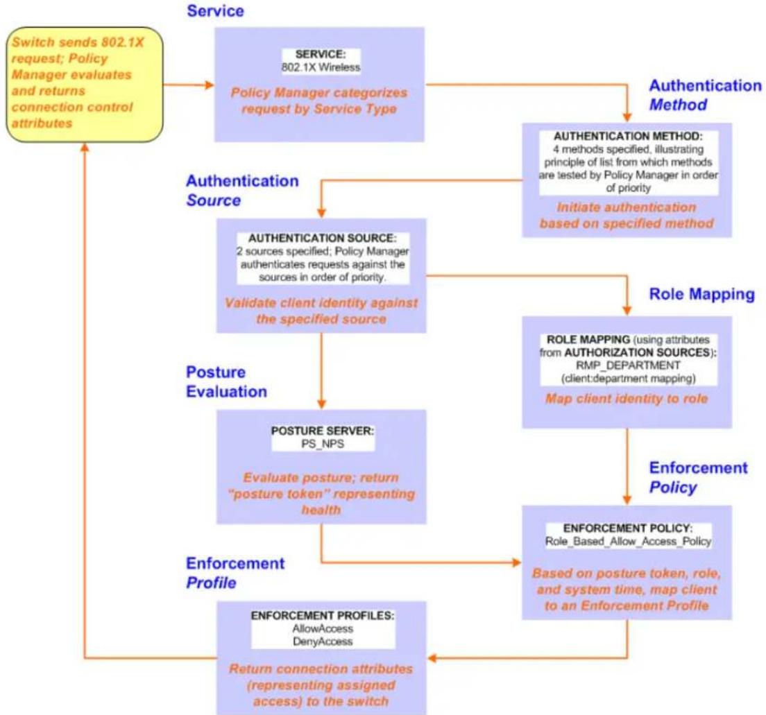
flowchart
graph TD
    A["Switch sends 802.1X request; Policy Manager evaluates and returns connection control attributes"] --> B["Service: 802.1X Wireless\nPolicy Manager categorizes request by Service Type"]
    B --> C["Authentication Method"]
    C --> D["AUTHENTICATION METHOD: 4 methods specified, illustrating principle of list from which methods are tested by Policy Manager in order of priority\nInitiate authentication based on specified method"]
    D --> E["Validation client identity against the specified source"]
    E --> F["POSTURE Evaluation"]
    F --> G["POSTURE SERVER: PS_NPS\nEvaluate posture; return "posture token" representing health"]
    G --> H["Enforcement Profile"]
    H --> I["ENFORCEMENT PROFILES: AllowAccess DenyAccess\nReturn connection attributes (representing assigned access) to the switch"]
    I --> J["Role Mapping"]
    J --> K["ROLE MAPPING (using attributes from AUTHORIZATION SOURCES): RMP_DEPARTMENT (client:department mapping)\nMap client identity to role"]
    K --> L["Enforcement Policy"]
    L --> M["ENFORCEMENT POLICY: Role_Based_Allow_Access_Policy\nBased on posture token, role, and system time, map client to an Enforcement Profile"]
    M --> I

Policy Manager ships with fourteen preconfigured services. In this use case, you select a service that sup 802.1X wireless requests. Follow the steps below to configure this basic 802.1X service that uses [EAP FAST], one of the pre-configured Policy Manager authentication methods, and Active Directory Authentication Source (AD), an external authentication source within your existing enterprise.
Policy Manager fetches attributes used for role mapping from the authorization sources (that are associated with the authentication source). In this example, the authentication and authorization source are one and the same.
Policy Manager tests client identity against role-mapping rules, appending any match (multiple roles acceptable) to the request for use by the enforcement policy. In the event of role-mapping failure, Policy Manager assigns a default role. This use case create the role mapping policy RMP_DEPARTMENT that distinguishes clients by department and the corresponding roles ROLE_ENGINEERING and ROLE_FINANCE, to which it maps.
Policy Manager can be configured for a third-party posture server, to evaluate client health based on ver specific credentials, typically credentials that cannot be evaluated internally by Policy Manager (that is, no the form of internal posture policies). Currently, Policy Manager supports the following posture server interface: Microsoft NPS (RADIUS).

For purposes of posture evaluation, you can configure a posture policy (internal to Policy Manager), a posture serve (external), or an audit server (internal or external). Each of the first three use cases demonstrates one of these options; here, the posture server.
Configuring a Service
- Navigate to Configuration > Services.
- Click the Add icon to add a service. The Configuration > Services > Add window opens.
- If it is not already selected, click the Service tab and define basic service information.
a. Enter a name for the service in the Name field.
b. Click the Type drop-down list and select 802.1X Wireless.
c. (Optional) click the Monitor Mode checkbox to allow handshakes to occur (for monitoring purposes), without enforcement.
d. Click Next to display the Authentication tab.
- Configure authentication.
a. In the Authentication Methods field, select [EAP Fast].
b. In the Authentication Sources field, click the Select to Add drop-down list and select the following sources.
■ [Local User Repository] [Local SQL DB]
■ [Guest User Repository] [Local SQL DB]
■ [Guest Device Repository] [Local SQL DB]
■ [Endpoints Repository] [Local SQL DB]
■ [Onboard Devices Repository] [Local SQL DB]
■ [Admin User Repository] [Local SQL DB]
■ [Active Directory]
c. (Optional) Select Strip Username Rules to pre-process the user name (to remove prefixes and suffixes) before sending it to the authentication source.
Creating a New Role Mapping Policy
To create a new Role Mapping policy:
- Click the Roles tab.
- Click Add new Role Mapping Policy. The Role Mappings page opens.
Figure 821: Role Mapping Navigation and Settings
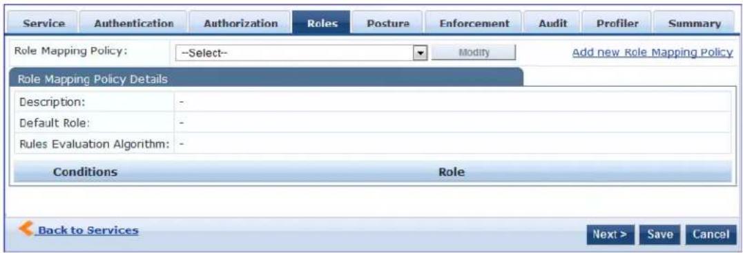
- Add a new role, navigate to the Policy tab. Enter the Policy Name, For example, ROLE_ENGINEER and click Save. Repeat the same step for ROLE_FINANCE. The following figure displays the Policy tab:
Figure 822: Policy Tab
![Configuration » Identity » Role Mappings » Add Role Mappings Policy Mapping Rules Summary Policy Name: RMP_DEPARTMENT Description: Default Role: [Guest] View Details Modify Add new Role Add New Role Name: ROLE_FINANCE Cancel Add New Role Name: ROLE_ENGINEER Description: Save Cancel](/content/2026/05/842116/images/91ef8e41f50d26b0fbe31e9da54127185b31f06d78688732c9e7c8979894997d.jpg)
- Click the Next button in the Rules Editor.
- Create rules to map client identity to a role. From the Mapping Rules tab, select the Rules Evaluation Algorithm radio button. The following figure displays the Mapping Rules tab:
Figure 823: Mapping Rules Tab
![Configuration » Identity » Role Mappings » Add Role Mappings Policy Mapping Rules Summary Rules Evaluation Algorithm: Select first match Select all matches Role Mapping Rules: Conditions Role Name 1. (Authorization: AD:department CONTAINS engineer) Role_Engineer 2. (Authorization: AD:department CONTAINS finance) ROLE_FINANCE Add Rule Move Up Move Down Edit Rule Remove Rule Rules Editor Conditions Matches ANY or ALL of the following conditions: Type Name Operator Value 1. Authorization: AD department CONTAINS finance 2. Click to add... Actions Role Name: [Contractor] [Contractor] [Employee] [Guest] [Other] [TACACS API Admin] [TACACS Help Desk] [TACACS Network Admin] [TACACS Read-only Admin] [TACACS Receptionist] [TACACS Super Admin] Back to Role Mappings Next > Save Cancel](/content/2026/05/842116/images/3cfdea5b665bf313b46ad99b075dba74263e1f3c973c683307e6193a806005e8.jpg)
- Select the Select all matches radio button.
- Match the conditions with the role name. Click the Add Rule button. The Rules Editor pop-up opens. Upon completion of each rule, click the Save button in the Rules Editor.
- Click the Save button.
- Add the new role mapping policy to the service from the Roles tab. The following figure displays the Roles tab:
Figure 824: Roles Tab
![Service Authentication Authorization Roles Posture Audit Enforcement Summary Role Mapping Policy: RMP_DEPARTMENT Modify Add new Role Mapping Policy Role Mapping Policy Details Description: - Default Role: [Guest] Rules Evaluation Algorithm: evaluate-all Conditions Role 1. (Authorization:AD:department CONTAINS engineer) Role_Engineer 2. (Authorization:AD:department CONTAINS finance) ROLE_FINANCE Back to Services Next > Save Cancel](/content/2026/05/842116/images/39c682ccc6e371c3ec2ab693f518a505e6593020cd1bda5d582a96dec8091042.jpg)
- Select Role Mapping Policy, for example, RMP_DEPARTMENT. Click Next.
- Add an Microsoft NPS external posture server to the 802.1X service. Click the Posture tab. The following figure displays the Posture tab:
Figure 825: Posture Tab
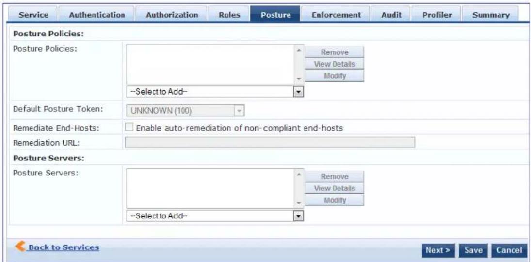
12.Click Add new Posture Server to add a new posture server.
13. Configure the following posture settings examples:
• Name (freeform): PS_NPS
• Server Type radio button: Microsoft NPS
- Default Posture Token (selector): UNKOWN
The following figure displays the Posture Server tab:
Figure 826: Posture Server Tab
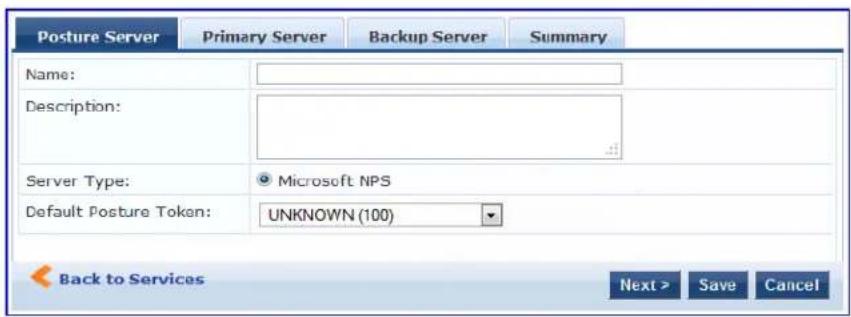
14.Click Next.
15. Configure connection settings in the Primary/ Backup Server tabs by entering the connection information for the RADIUS posture server. The following figure displays the Primary Server tab:
Figure 827: Primary Server Tab
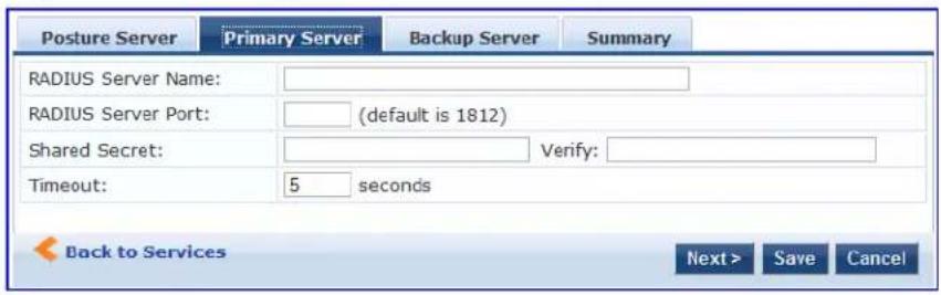
- Click Next from primary server to backup server. Click Save.
- Add the new posture server to the service. From the Posture tab, enter the Posture Servers, for example, PS_NPS, then click the Add button. The following figure displays the Posture tab:
Figure 828: Posture Tab
![Service Authentication Authorization Roles Posture Enforcement Audit Profiler Summary Posture Policies: Posture Policies: Remove Add new Posture Policy View Details Modify --Select-- Add Default Posture Token: UNKNOWN (100) Remediate End-Hosts: Enable auto-remediation of non-compliant end-hosts Remediation URL: Posture Servers: Posture Servers: PS_NPS [RADIUS] Remove Add new Posture Server --Select-- Add Back to Services Next > Save Cancel](/content/2026/05/842116/images/323e28b0067fdd0e83859204875f79e68cbeb4158f336fa935268626936ffc50.jpg)
- Click the Next button. Assign an enforcement policy.
- Enforcement policies contain dictionary-based rules for evaluation of Role, Posture Tokens, and System Time to evaluation profiles. Policy Manager applies all matching enforcement profiles to the request. In case of no match, Policy Manager assigns a default enforcement profile. The following figure displays Enforcement tab:
Table 458: Enforcement Policy Navigation and Settings
![Service Authentication Roles Posture Enforcement Audit Profiler Summary Use Cached Results: Use cached Roles and Posture attributes from previous sessions Enforcement Policy: [Sample Allow Access Policy] Modify Add new Enforcement Policy Enforcement Policy Details Description: Sample policy to allow network access Default Profile: [Allow Access Profile] Rules Evaluation Algorithm: evaluate-all Conditions Enforcement Profiles 1. (Date:Day-of-Week BELONGS_TO Monday, Tuesday, Wednesday, Thursday, Friday, Saturday, Sunday) [Allow Access Profile] Back to Services Next > Save Cancel](/content/2026/05/842116/images/ee51f517abd03bd9e5517447ff13531627da5d0714c0d325b854b0575a69acb2.jpg)
- From the Enforcement tab, select the Enforcement Policy. For instructions about how to build an enforcement policy, refer to Configuring Enforcement Policies on page 371.
21.Save the service.
Web Based Authentication Use Case
This Service supports known Guests with inadequate 802.1X supplicants or posture agents. The following figure illustrates the overall flow of control for this Policy Manager Service.
Figure 829: Flow-of-Control of Web-Based Authentication for Guests
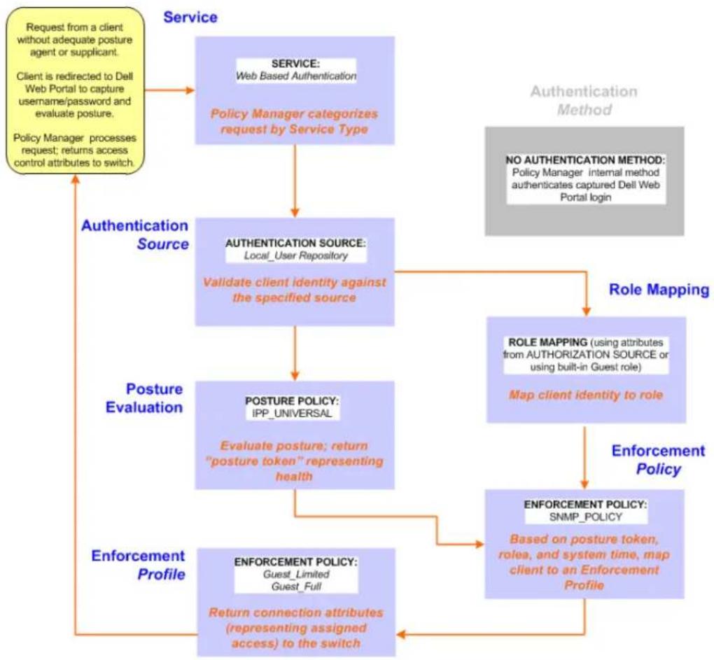
flowchart
graph TD
A["Request from a client without adequate posture agent or supplicant.<br>Client is redirected to Dell Web Portal to capture username/password and evaluate posture.<br>Policy Manager processes request; returns access control attributes to switch."] --> B["Authentication Source"]
B --> C["Validation client identity against the specified source"]
C --> D["POSTURE POLICY: IPP_UNIVERSAL"]
D --> E["Evaluate posture; return "posture token" representing health"]
E --> F["ENFORCEMENT POLICY: Guest_Limited Guest_Full"]
F --> G["Return connection attributes (representing assigned access) to the switch"]
H["Authentication Method"] --> I["No AUTHENTICATION METHOD: Policy Manager internal method authenticates captured Dell Web Portal login"]
I --> J["Role Mapping"]
J --> K["ROLE MAPPING (using attributes from AUTHORIZATION SOURCE or using built-in Guest role)"]
K --> L["Map client identity to role"]
L --> M["Enforcement Policy"]
M --> N["ENFORCEMENT POLICY: SNMP_POLICY"]
N --> O["Based on posture token, rolea, and system time, map client to an Enforcement Profile"]
O --> P["Enforcement Profile"]
Q["Posture Evaluation"] --> D
Q --> E
Q --> M
Configuring a Service
Perform the following steps to configure Policy Manager for WebAuth-based Guest access.
- Prepare the switch to pre-process WebAuth requests for the Policy Manager Dell WebAuth service.
Refer to your Network Access Device documentation to configure the switch such that it redirects HTT requests to the Dell Guest Portal, which captures username and password and optionally launches an agent that returns posture data.
- Create a WebAuth-based Service.
Table 459: Service Navigation and Settings
| Navigation Settings | |
| Create a new Service:Services>Add Service > | Configuration + Services:ServicesAddImportExport All |
| Name the Service and select a pre-configured Service Type:Service (tab) >Type (selector): Dell Web-Based Authentication >Name/Description (freeform) >Upon completion, click Next. | 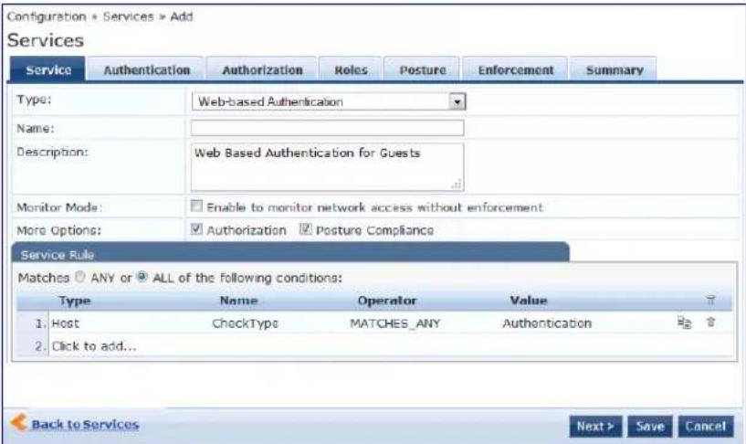 |
- Set up the Authentication.
a. Method: The Policy Manager WebAuth service authenticates WebAuth clients internally.
b. Source: Administrators typically configure Guest Users in the local Policy Manager database.
- Configure a Posture Policy.
For purposes of posture evaluation, you can configure a Posture Policy (internal to Policy Manager), a Posture Serve (external), or an Audit Server (internal or external). Each of the first three use cases demonstrates one of these options. This use case demonstrates the Posture Policy.
As of the current version, Policy Manager ships with five pre-configured posture plugins that evaluate health of the client and return a corresponding posture token.
To add the internal posture policy IPP_UNIVERSAL_XP, which (as you will configure it in this Use Case, checks any Windows® XP clients to verify the most current Service Pack).

Table 460: Local Policy Manager Database Navigation and Settings
| Navigation Settings | |
| Select the local Policy Manager database:Authentication (tab) >Sources (Select drop-down list): [Local User Repository] >Add >Strip Username Rules(check box) >Enter an example of preceding or following separators (if any), with the phrase “user” representing the username to be returned. For authentication, Policy Manager strips the specified separators and any paths or domains beyond them.Upon completion, click Next (until you reach Enforcement Policy). | 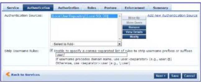 |
Table 461: Posture Policy Navigation and Settings
| Navigation Setting | |
| Create a Posture Policy:Posture(tab) >Enable Validation Check(check box) >Add new Internal Policy (link)> | 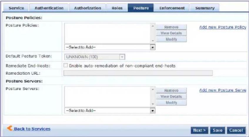 |
| Name the Posture Policy and specify a general class of operating system:Policy (tab)>Policy Name(freeform):IPP_UNIVERSAL>Host Operating System(radio buttons):Windows>When finished working in the Policy tab, click Next to open the Posture Plugins tab | 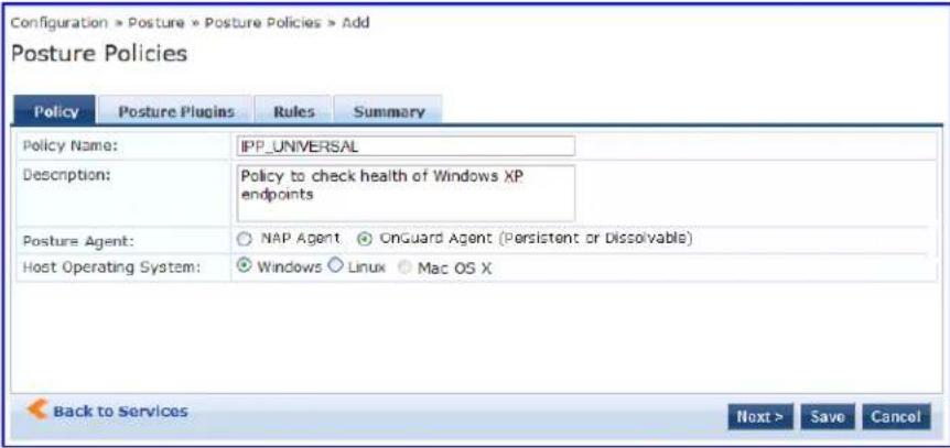 |
| Select a Validator:Posture Plugins (tab)>Enable Windows Health System Validator >Configure (button) > | 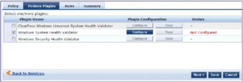 |
| Configure the Validator:Windows System Health Validator (popup) >Enable all Windows operating systems(check box) >Enable Service Pack levels for Windows 7, Windows Vista®, Windows XP Windows Server®2008, Windows Server 2008 R2, and Windows Server 2003(check boxes) >Save(button) > | 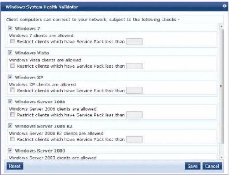 |
| When finished working in the Posture Plugin tab click Next to move to the Rules tab) | |
| Set rules to correlate validation results with posture tokens:Rules (tab) >Add Rule (button opens popup) >Rules Editor (popup) >Conditions/Actions: match Conditions (Select Plugin/ Select Plugin checks) to Actions (Posture Token)>In the Rules Editor, upon completion of each rule, click the Save button>When finished working in the Rules tab, click the Next button. | 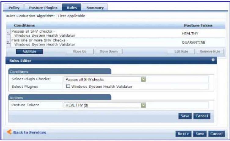 |
Table 461: Posture Policy Navigation and Settings (Continued)
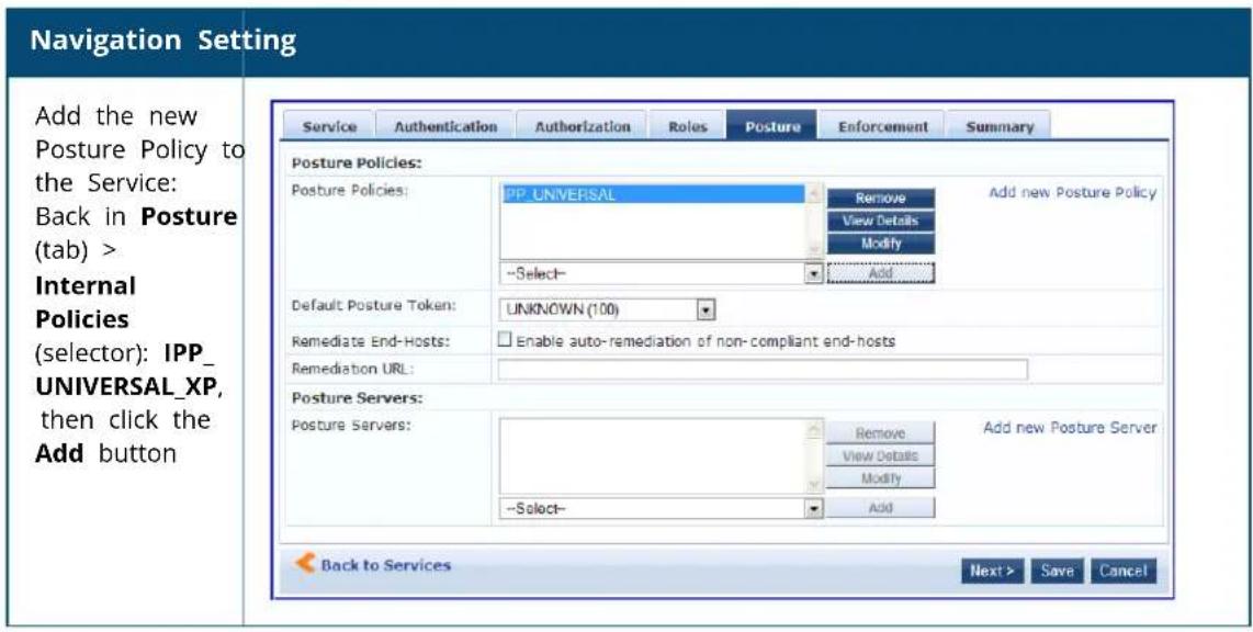
The following fields deserve special mention:
■ Default Posture Token. Value of the posture token to use if health status is not available.
- Remediate End-Hosts. When a client does not pass posture evaluation, redirect to the indicated server for remediation.
■ Remediation URL. URL of remediation server.
5. Create an Enforcement Policy.
Because this Use Case assumes the Guest role, and the Dell Web Portal agent has returned a posture token, it does not require configuration of Role Mapping or Posture Evaluation.
The SNMP_POLICY selected in this step provides full guest access to a Role of [Guest] with a Posture of Healthy, an limited guest access.
Table 462: Enforcement Policy Navigation and Settings
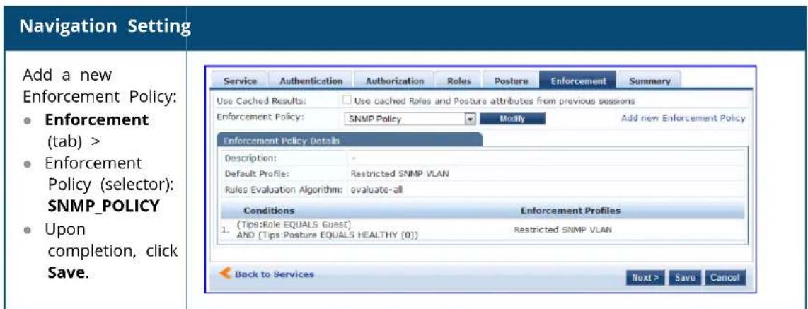
6. Save the Service.
Click Save. The Service now appears at the bottom of the Services list.

MAC Authentication Use Case
This service supports Network Devices, such as printers or hand-helds.
In this service, an audit is initiated on receiving the first MAC Authentication request. A subsequent MAC Authentication request (triggered after the audit, or triggered after a short session timeout) uses the cach results from the audit to determine the posture and role(s) for the device.
The following diagram illustrates the overall flow of control for this Policy Manager service.
Figure 830: Flow-of-Control of MAC Authentication for Network Devices
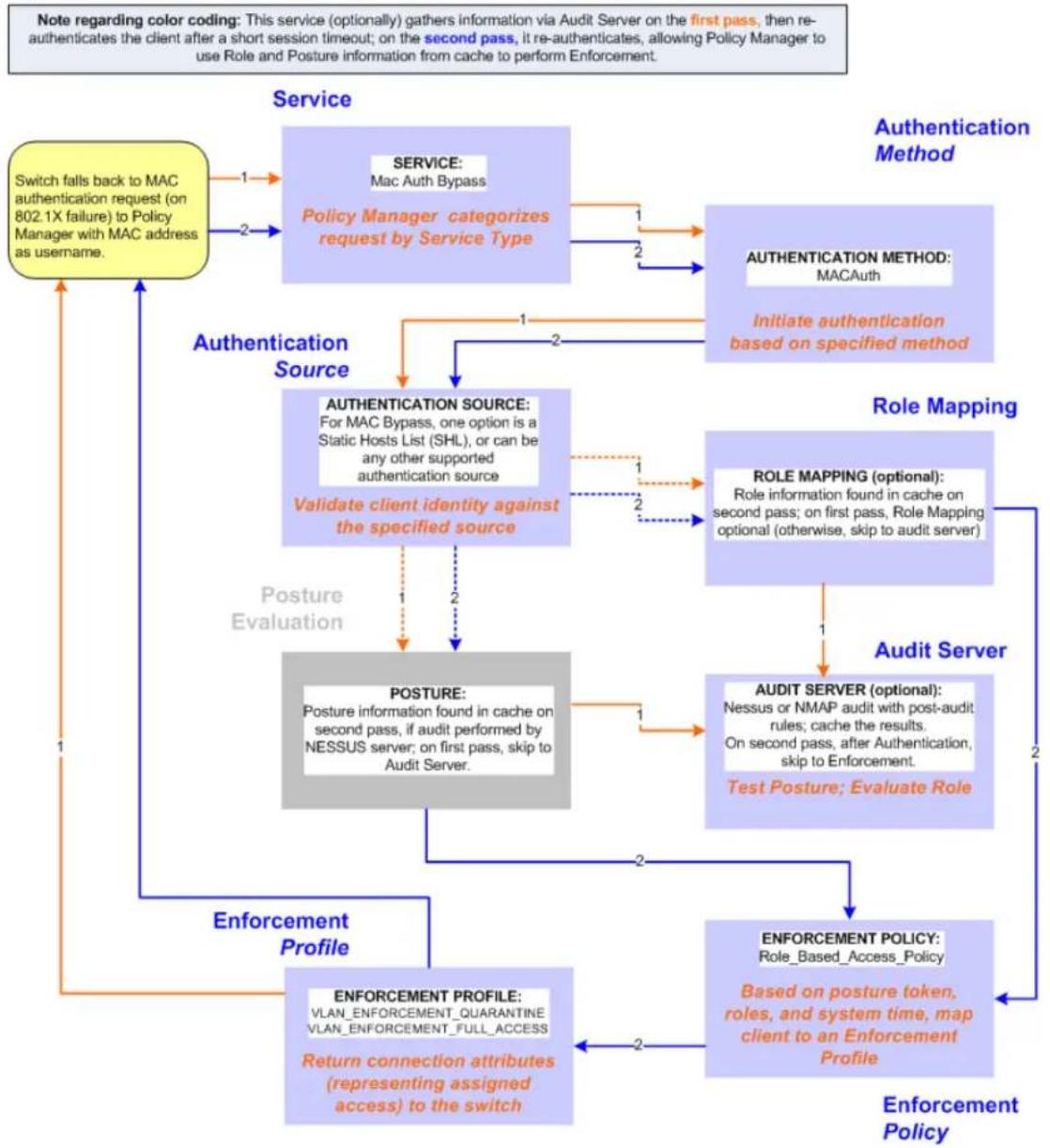
flowchart
graph TD
    A["Switch falls back to MAC authentication request (on 802.1X failure) to Policy Manager with MAC address as username."] -->|1| B["Service: Mac Auth Bypass"]
    A -->|2| C["Policy Manager categorizes request by Service Type"]
    B -->|1| D["Authentication Method: MACAuth"]
    B -->|2| E["Initiate authentication based on specified method"]
    C -->|1| F["Authentication Source: For MAC Bypass, one option is a Static Hosts List (SHL), or can be any other supported authentication source"]
    C -->|2| G["Validate client identity against the specified source"]
    F --> H["POSTURE: Posture information found in cache on second pass, if audit performed by NESSUS server; on first pass, skip to Audit Server."]
    G --> I["POSTURE: Posture information found in cache on second pass, if audit performed by NESSUS server; on first pass, skip to Audit Server."]
    H --> J["Audit Server: Role Mapping (optional): Nessus or NMAP audit with post-audit rules; cache the results. On second pass, after Authentication, skip to Enforcement."]
    I --> K["Test Posture: Evaluate Role"]
    J --> L["ENFORCEMENT POLICY: Role-Based_Access_Policy"]
    K --> M["Enforcement Policy: Based on posture token, roles, and system time, map client to an Enforcement Profile"]
    L --> M
    M --> N["Return connection attributes (representing assigned access) to the switch"]
    N --> O["Enforcement Profile: VLAN_ENFORCEMENT_QUARANTINE VLAN_ENFORCEMENT_FULL_ACCESS"]
    O --> P["Posture Evaluation"]
    P --> Q["Authentication Source"]
    Q --> R["Validation Client Identity Against the Specified Source"]
    R --> S["Posture Evaluation"]
    S --> T["Posture Information Found in Cache on second pass, if audit performed by NESSUS server; on first pass, skip to Audit Server."]
    T --> U["Posture Information Found in Cache on second pass, if audit performed by NESSUS server; on first pass, skip to Audit Server."]
    U --> V["Posture Information Found in Cache on second pass, if audit performed by NESSUS server; on first pass, skip to Audit Server."]
    V --> W["Posture Information Found in Cache on second pass, if audit performed by NESSUS server; on first pass, skip to Audit Server."]
    W --> X["Posture Information Found in Cache on second pass, if audit performed by NESSUS server; on first pass, skip to Audit Server."]
    X --> Y["Posture Information Found in Cache on second pass, if audit performed by NESSUS server; on first pass, skip to Audit Server."]
    Y --> Z["Posture Information Found in Cache on second pass, if audit performed by NESSUS server; on first pass, skip to Audit Server."]
    Z --> AA["Posture Information Found in Cache on second pass, if audit performed by NESSUS server; on first pass, skip to Audit Server."]
    AA --> AB["Posture Information Found in Cache on second pass, if audit performed by NESSUS server; on first pass, skip to Audit Server."]
    AB --> AC["Posture Information Found in Cache on second pass, if audit performed by NESSUS server; on first pass, skip to Audit Server."]
    AC --> AD["Posture Information Found in Cache on second pass, if audit performed by NESSUS server; on first pass, skip to Audit Server."]
    AD --> AE["Posture Information Found in Cache on second pass, if audit performed by NESSUS server; on first pass, skip to Audit Server."]
    AE --> AF["Posture Information Found in Cache on second pass, if audit performed by NESSUS server; on first pass, skip to Audit Server."]
    AF --> AG["Posture Information Found in Cache on second pass, if audit performed by NESSUS server; on first pass, skip to Audit Server."]
    AG --> AH["Posture Information Found in Cache on second pass, if audit performed by NESSUS server; on first pass, skip to Audit Server."]
    AH --> AI["Posture Information Found in Cache on second pass, if audit performed by NESSUS server; on first pass, skip to Audit Server."]
    AI --> AJ["Posture Information Found in Cache on second pass, if audit performed by NESSUS server; on first pass, skip to Audit Server."]
    AJ --> AK["Posture Information Found in Cache on second pass, if audit performed by NESSUS server; on first pass, skip to Audit Server."]
    AK --> AL["Posture Information Found in Cache on second pass, if audit performed by NESSUS server; on first pass, skip to Audit Server."]
    AL --> AM["Posture Information Found in Cache on second pass, if audit performed by NESSUS server; on first pass, skip to Audit Server."]
    AM --> AN["Posture Information Found in Cache on second pass, if audit performed by NESSUS server; on first pass, skip to Audit Server."]
    AN --> AO["Posture Information Found in Cache on second pass, if audit performed by NESSUS server; on first pass, skip to Audit Server."]
    AO --> AP["Posture Information Found in Cache on second pass, if audit performed by NESSUS server; on first pass, skip to Audit Server."]
    AP --> AQ["Posture Information Found in Cache on second pass, if audit performed by NESSUS server; on first pass, skip to Audit Server."]
    AQ --> AR["Posture Information Found in Cache on second pass, if audit performed by NESSUS server; on first pass, skip to Audit Server."]
    AR --> AS["Posture Information Found in Cache on second pass, if audit performed by NESSUS server; on first pass, skip to Audit Server."]
    AS --> AT["Posture Information Found in Cache on second pass, if audit performed by NESSUS server; on first pass, skip to Audit Server."]
    AT --> AU["Posture Information Found in Cache on second pass, if audit performed by NESSUS server; on first pass, skip to Audit Server."]
    AU --> AV["Posture Information Found in Cache on second pass, if audit performed by NESSUS server; on first pass, skip to Audit Server."]
    AV --> AW["Posture Information Found in Cache on second pass, if audit performed by NESSUS server; on first pass, skip to Audit Server."]
    AW --> AX["Posture Information Found in Cache on second pass, if audit performed by NESSUS server; on first pass, skip to Audit Server."]
    AX --> AY["Posture Information Found in Cache on second pass, if audit performed by NESSUS server; on first pass, skip to Audit Server."]
    AY --> AZ["Posture Information Found in Cache on second pass, if audit performed by NESSUS server; on first pass, skip to Audit Server."]
    AZ --> BA["Posture Information Found in Cache on second pass, if audit performed by NESSUS server; on first pass, skip to Audit Server."]
    BA --> BB["Posture Information Found in Cache on second pass, if audit performed by NESSUS server; on first pass, skip to Audit Server."]
    BB --> BC["Posture Information Found in Cache on second pass, if audit performed by NESSUS server; on first pass, skip to Audit Server."]
    BC --> BD["Posture Information Found in Cache on second pass, if audit performed by NESSUS server; on first pass, skip to Audit Server."]
    BD --> BE["Posture Information Found in Cache on second pass, if audit performed by NESSUS server; on first pass, skip to Audit Server."]
    BE --> BF["Posture Information Found in Cache on second pass, if audit performed by NESSUS server; on first pass, skip to Audit Server."]
    BF --> BG["Posture Information Found in Cache on second pass, if audit performed by NESSUS server; on first pass, skip to Audit Server."]
    BG --> BH["Posture Information Found in Cache on second pass, if audit performed by NESSUS server; on first pass, skip to Audit Server."]
    BH --> BI["Posture Information Found in Cache on second pass, if audit performed by NESSUS server; on first pass, skip to Audit Server."]
    BI --> BJ["Posture Information Found in Cache on second pass, if audit performed by NESSUS server; on first pass, skip to Audit Server."]
    BJ --> BK["Posture Information Found in Cache on second pass, if audit performed by NESSUS server; on first pass, skip to Audit Server."]
    BK --> BL["Posture Information Found in Cache on second pass, if audit performed by NESSUS server; on first pass, skip to Audit Server."]
    BL --> BM["Posture Information Found in Cache on second pass, if audit performed by NESSUS server; on first pass, skip to Audit Server."]
    BM --> BN["Posture Information Found in Cache on second pass, if audit performed by NESSUS server; on first pass, skip to Audit Server."]
    BN --> BO["Posture Information Found in Cache on second pass, if audit performed by NESSUS server; on first pass, skip to Audit Server."]
    BO --> BP["Posture Information Found in Cache on second pass, if audit performed by NESSUS server; on first pass, skip to Audit Server."]
    BP --> BQ["Posture Information Found in Cache on second pass, if audit performed by NESSUS server; on first pass, skip to Audit Server."]
    BQ --> BR["Posture Information Found in Cache on second pass, if audit performed by NESSUS server; on first pass, skip to Audit Server."]
    BR --> BS["Posture Information Found in Cache on second pass, if audit performed by NESSUS server; on first pass, skip to Audit Server."]
    BS --> BT["Posture Information Found in Cache on second pass, if audit performed by NESSUS server; on first pass, skip to Audit Server."]
    BT --> BU["Posture Information Found in Cache on second pass, if audit performed by NESSUS server; on first pass, skip to Audit Server."]
    BU --> BV["Posture Information Found in Cache on second pass, if audit performed by NESSUS server; on first pass, skip to Audit Server."]
    BV --> BW["Posture Information Found in Cache on second pass, if audit performed by NESSUS server; on first pass, skip to Audit Server."]
    BW --> BX["Posture Information Found in Cache on second pass, if audit performed by NESSUS server; on first pass, skip to Audit Server."]
    BX --> BY["Posture Information Found in Cache on second pass, if audit performed by NESSUS server; on first pass, skip to Audit Server."]
    BY --> BZ["Posture Information Found in Cache on second pass, if audit performed by NESSUS server; on first pass, skip to Audit Server."]
    BZ --> CA["Posture Information Found in Cache on second pass, if audit performed by NESSUS server; on first pass, skip to Audit Server."]
    CA --> CB["Posture Information Found in Cache on second pass, if audit performed by NESSUS server; on first pass, skip to Audit Server."]
    CB --> CC["Posture Information Found in Cache on second pass, if audit performed by NESSUS server; on first pass, skip to Audit Server."]
    CC --> CD["Posture Information Found in Cache on second pass, if audit performed by NESSUS server; on first pass, skip to Audit Server."]
    CD --> CE["Posture Information Found in Cache on second pass, if audit performed by NESSUS server; on first pass, skip to Audit Server."]
    CE --> CF["Posture Information Found in Cache on second pass, if audit performed by NESSUS server; on first pass, skip to Audit Server."]
    CF --> CG["Posture Information Found in Cache on second pass, if audit performed by NESSUS server; on first pass, skip to Audit Server."]
    CG --> CH["Posture Information Found in Cache on second pass, if audit performed by NESSUS server; on first pass, skip to Audit Server."]
    CH --> CI["Posture Information Found in Cache on second pass, if audit performed by NESSUS server; on first pass, skip to Audit Server."]
    CI --> CJ["Posture Information Found in Cache on second pass, if audit performed by NESSUS server; on first pass, skip to Audit Server."]
    CJ --> CK["Posture Information Found in Cache on second pass, if audit performed by NESSUS server; on first pass, skip to Audit Server."]
Configuring the Service
To configure W-ClearPass for MAC-based network device access:
- First create a MAC Authentication Service by navigating to Configuration > Services.
The Services page opens.
- Click the Add link.
The Add Services dialog opens.
Figure 831: MAC Authentication Service Configuration Dialog
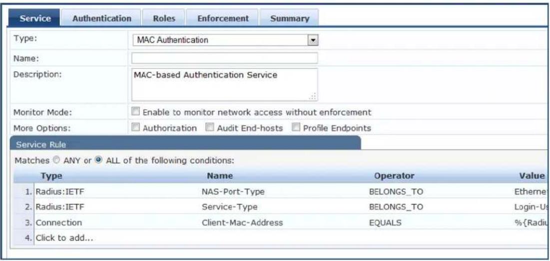
3.
Table 463: MAC Authentication Service Navigation and Settings
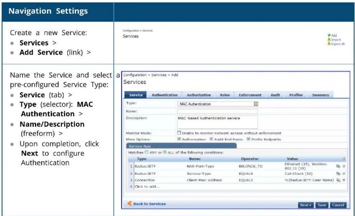
- Set up Authentication.
You can select any type of authentication/authorization source for a MAC Authentication service. Only static host list of type MAC Address List or MAC Address Regular Expression shows up in the list of authentication sources (of type Static Host List).
For more information on static host list, see Managing Static Host Lists on page 268. You can also select any other supported type of authentication source.
Table 464: Authentication Method Navigation and Settings
| Navigation Settings | |
| Select an Authentication Method and two authentication sources—one of type Static Host List and the other of type Generic LDAP server (that you have already configured in Policy Manager):Authentication (tab) >Methods (This method is automatically selected for this type of service): [MAC AUTH] >Add >Sources (Select drop-down list): Handhelds [Static Host List] and Policy Manager Clients White List [Generic LDAP] >Add >Upon completion, Next (to Audit) | 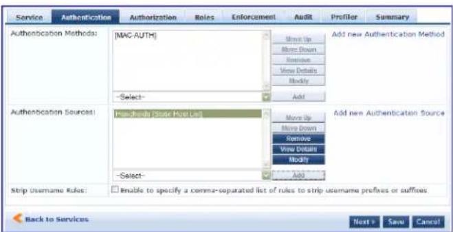 |
- Configure an Audit Server.
This step is optional if no Role Mapping Policy is provided, or if you want to establish health or roles audit. For more information, see Configuring Audit Servers on page 355.
An audit server determines health by performing a detailed system and health vulnerability analysis (Nessus).
You can also configure the audit server (Nmap or Nessus) with post-audit rules that enable Policy Ma to determine client identity.
Table 465: Audit Server Navigation and Settings
| Navigation Settings | |
| Configure the Audit Server:Audit (tab) >Audit End Hosts (enable) >Audit Server (selector):NMAPTrigger Conditions (radio button): For MAC authentication requestsReauthenticate client (check box): Enable | 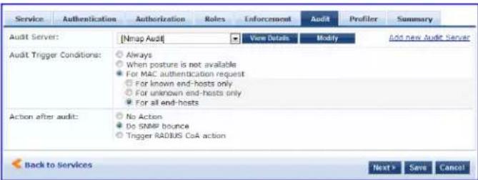 |
Upon completion of the audit, Policy Manager caches Role (Nmap and Nessus) and Posture (Nessus), it resets the connection (or the switch reauthenticates after a short session timeout), triggering a new re
which follows the same path until it reaches Role Mapping/Posture/Audit; this appends cached informa for this client to the request for passing to Enforcement.
- Select the Enforcement Policy Sample_Allow_Access_Policy:
Table 466: Enforcement Policy Navigation and Settings
| Navigation Setting | |
| Select the Enforcement Policy:Enforcement (tab) >Use Cached Results (check box): Select Use cached Roles and Posture attributes from previous sessions >Enforcement Policy (selector):UnmanagedClientPolicyWhen you are finished with your work in this tab, click Save. | 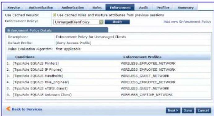 |
Unlike the 802.1X service, which uses the same Enforcement Policy (but uses an explicit Role Mapping Policy to assess Role), in this use case, Policy Manager applies post-audit rules against attributes captured by the Audit server to infer Role(s).
- Click Save.
The service now appears at the bottom of the Services list.
TACACS+ Use Case
This Service supports Administrator connections to Network Access Devices via TACACS+. The following im illustrates the overall flow of control for this Policy Manager Service.
Figure 832: Administrator connections to Network Access Devices via TACACS+
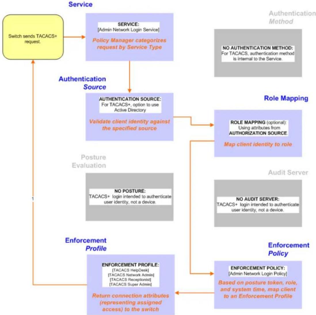
flowchart
graph TD
    A["Switch sends TACACS+ request."] --> B["SERVICE: [Admin Network Login Service"]]
    B --> C["Policy Manager categorizes request by Service Type"]
    C --> D["Authentication Source"]
    D --> E["AUTHENTICATION SOURCE: For TACACS+, option to use Active Directory"]
    E --> F["Validate client identity against the specified source"]
    F --> G["Role Mapping"]
    G --> H["ROLE MAPPING (optional): Using attributes from AUTHORIZATION SOURCE"]
    H --> I["Map client identity to role"]
    I --> J["Posture Evaluation"]
    J --> K["NO POSTURE: TACACS+ login intended to authenticate user identity, not a device"]
    K --> L["Enforcement Profile"]
    L --> M["ENFORCEMENT PROFILE: [TACACS HelpDesk"] [TACACS Network Admin] [TACACS Receptionist] [TACACS Super Admin]]
    M --> N["Return connection attributes (representing assigned access) to the switch"]
    N --> O["Enforcement Policy"]
    O --> P["ENFORCEMENT POLICY: [Admin Network Login Policy"]]
    P --> Q["Based on posture token, role, and system time, map client to an Enforcement Profile"]
Configuring the Service
Perform the following steps to configure Policy Manager for TACACS+-based access:
- Navigate to Configuration > Services.
- Click the Add icon to add a service. The Configuration > Services > Add window opens.
- If it is not already selected, click the Service tab and define basic service information.
a. Enter a name for the service in the Name field.
b. Click the Type drop-down list and select the preconfigured service type that matches your Policy Manager Admin Network Login Service.
c. Click Next to display the Authentication tab.
- Define the Authentication settings for the service. Authentication methods can be left to their default values, as the Policy Manager TACACS+ service authenticates TACACS+ requests internally.
a. In the Authentication Sources section, click the Select to Add drop-down list.
b. Select AD (Active Directory). For this use case example, Network Access Device authentication data will be stored in the Active Directory.
- Click the Enforcement tab and select an Enforcement Policy.
a. Click the Enforcement Policy drop-down list and select the Enforcement Policy [Admin Network Login Policy] that distinguishes the two allowed roles (Net Admin Limited and Device SuperAdmin).
- Click Save. The Service now appears at the bottom of the Services list.
Single Port Use Case
This Service supports all three types of connections on a single port.
The following figure illustrates both the overall flow of control for this hybrid service, in which complete switch and Policy Manager configurations allow all three types of connections on a single port:
Figure 833: Flow of the Multiple Protocol Per Port Case
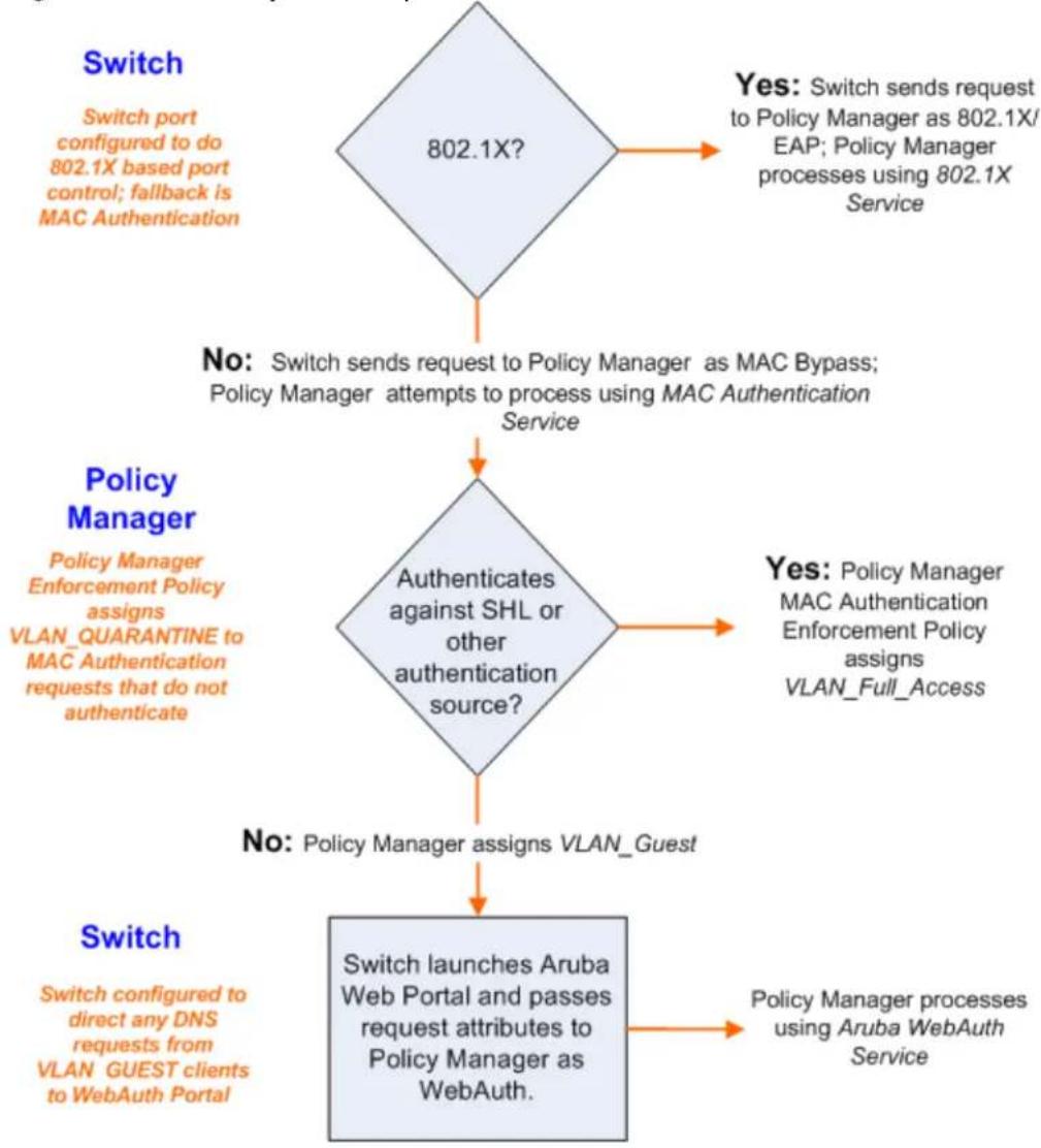
flowchart
graph TD
    A["Switch\nSwitch port configured to do 802.1X based port control; fallback is MAC Authentication"] --> B{802.1X?}
    B -->|Yes: Switch sends request to Policy Manager as 802.1X/EAP; Policy Manager processes using 802.1X Service| C["No: Switch sends request to Policy Manager as MAC Bypass; Policy Manager attempts to process using MAC Authentication Service"]
    C --> D{Authenticates against SHL or other authentication source?}
    D -->|Yes: Policy Manager MAC Authentication Enforcement Policy assigns VLAN_Full_Access| E["No: Policy Manager assigns VLAN_Guest"]
    E --> F["Switch launches Aruba Web Portal and passes request attributes to Policy Manager as WebAuth."]
    F --> G["Policy Manager processes using Aruba WebAuth Service"]
    H["Switch\nSwitch configured to direct any DNS requests from VLAN_GUEST clients to WebAuth Portal"] --> F
The Policy Manager administration User Interface allows you to create different types of objects:
- Service rules
• Role mapping policies
• Internal user policies
• Enforcement policies
• Enforcement profiles
• Post-audit rules
• Proxy attribute pruning rules
• Filters for Access Tracker and activity reports - Attributes editing for policy simulation
When editing all these elements, you are presented with a tabular interface with the same column head.
- Type - Type is the namespace from which these attributes are defined. This is a drop-down list that contains namespaces defined in the system for the current editing context.
- Name - Name is the name of the attribute. This is a drop-down list with the names of the attributes present in the namespace.
- Operator - Operator is a list of operators appropriate for the data type of the attribute. The drop-down list shows the operators appropriate for data type on the left (that is, the attribute).
- Value - The value is the value of the attribute. Again, depending on the data type of the attribute, the value field can be a free-form one-line edit box, a free-form multi-line edit box, a drop-down list containing defined values (enumerated types), or a time or date widget.
In some editing interfaces (for example, enforcement profile and policy simulation attribute editing interface) the operator does not change; it is always the EQUALS operator.
Providing a uniform tabular interface to edit all these elements enables you to use the same steps while configuring these elements. Also, providing a context-sensitive editing experience (for names, operators and values) takes the guess-work out of configuring these elements.
The following sections describe namespaces, variables, and operators:
- Namespaces on page 919
• Variables on page 929 - Operators on page 930
Namespaces
Multiple namespaces are displayed in the rules editing interfaces, depending upon what you are editing. example, multiple namespaces are displayed when you are editing posture policies you work with the po namespace; when you are editing service rules you work with, among other namespaces, the RADIUS namespace, but not the posture namespace.
For detailed information about the available namespaces, see the following topics:
• Application Namespace on page 920
• Audit Namespaces on page 921
• Authentication Namespaces on page 921
• Authorization Namespaces on page 923
• Certificate Namespaces on page 924
• Connection Namespaces on page 925
• Date Namespaces on page 926
• Device Namespaces on page 926
• Endpoint Namespaces on page 927
• Guest User Namespaces on page 927
- Host Namespaces on page 927
- Local User Namespaces on page 927
• Posture Namespaces on page 928
• RADIUS Namespaces on page 928
• TACACS Namespaces on page 929
• Tips Namespaces on page 929
Application Namespace
The Application namespace has one name attribute. This attribute is an enumerated type currently contains the following string values:
- Guest
- Insight
- PolicyManager
- Onboard
W-ClearPass
The Application: ClearPass namespace has the following string values available for the Name field:
- AssertionConsumerUrl
- Configuration-Profile-ID
• Device-Compromised
• Device-ICCID
• Device-IMEI
• Device-MAC
• Device-MDM-Managed
• Device-NAME
• Device-OS
• Device-PRODUCT
• Device-SERIAL
• Device-UDID
• Device-VERSION
• IDDP-COOKIE-TIMEOUT-MINS
IDPURL
• MDM-Data-Roaming
• MDM-Voice-Roaming - Onboard-Max-Devices
Page-Name
• Provisioning-Settings-ID
- SAMLRequest
- SAMLResponse
- Session-Timeout
- User-Email-Address
Audit Namespaces
The dictionaries in the audit namespace come pre-packaged with the product. The Audit namespace has notation Vendor:Audit, where Vendor is the name of the company that has defined attributes in the dictionary.
Examples of dictionaries in the audit namespace are AvendaSystems:Audit or Qualys:Audit.
The Audit namespace appears when editing post-audit rules. See Audit Servers for more information.
The Avenda Systems: Audit namespace appears when editing post-audit rules for NESSUS and NMAP audit servers.
The following figure displays the Audit Namespace attributes:
Table 467: Audit Namespace Attributes
| Attribute Name Values | |
| Audit-Status • AUDIT_ERROR• AUDIT_INPROGRESS• AUDIT_SUCCESS | |
| Device-Type Type of device returned by an NMAP port scan. | |
| Output-Msgs The output message returned by Nessus plugin after a vulnerability scan. | |
| Network-Apps String representation of the open network ports (http, telnet, etc.). | |
| Mac-Vendor Vendor associated with MAC address of the host. | |
| OS-Info | OS information string returned by NMAP. |
| Open-Ports | The port numbers of open applications on the host. |
Authentication Namespaces
The authentication namespace can be used in role mapping policies to define roles based on the type of authentication method used or the status of the authentication.
Authentication Namespace Editing Context
The following table describes the Authentication Namespace Attributes parameters:
Table 468: Authentication Namespace Attributes
| Attribute Name | Values |
| InnerMethod | CHAPEAP-GTCEAP-MD5EAP-MSCHAPv2EAP-TLSMSCHAPPAPNOTE:The EAP-MD5 authentication type is not supported if you use the W-ClearPass Policy Manager in the FIPS mode. |
| OuterMethod | CHAPEAP-FASTEAP-MD5EAP-PEAPEAP-TLSEAP-TTLSMSCHAPPAPNOTE:The EAP-MD5 authentication type is not supported if you use the W-ClearPass Policy Manager in the FIPS mode. |
| Phase1PAC | None-No PAC was used to establish the outer tunnel in the EAP-FAST authentication methodTunnel-A tunnel PAC was used to establish the outer tunnel in the EAP-FAST authentication methodMachine-A machine PAC was used to establish the outer tunnel in the EAP-FAST authentication method; machine PAC is used for machine authentication (See EAP-FAST Adding and Configuring Authentication Methods on page 183). |
| Phase2PAC | None-No PAC was used instead of an inner method handshake in the EAP-FAST authentication methodUserAuthPAC-A user authentication PAC was used instead of the user authentication inner method handshake in the EAP-FAST authentication methodPosturePAC-A posture PAC was used instead of the posture credential handshake in the EAP-FAST authentication method |
| Posture | Capable-The client is capable of providing posture credentialsCollected- Posture credentials were collected from the clientNot-Capable-The client is not capable of providing posture credentialsUnknown- It is not known whether the client is capable of providing credentials |
| Status | None-No authentication took placeUser-The user was authenticatedMachine-The machine was authenticatedFailed- Authentication failedAuthSource-Unreachable- The authentication source was unreachable |
| MacAuth | NotApplicable- Not a MAC Auth requestKnown Client- Client MAC address was found in an authentication sourceUnknown Client- Client MAC address was not found in an authentication source |
| Username The | username as received from the client (after the strip user name rules are applied). |
| Full-Username | The username as received from the client (before the strip user name rules are applied). |
| Source The name of the authentication source used to authenticate the user. | |
Authorization Namespaces
Policy Manager supports multiple types of authorization sources. Authorization sources from which values attributes can be retrieved to create role mapping rules have their own separate namespaces (prefixed v Authorization).
Authorization editing context
Role mapping policies
AD Instance Namespace
For each instance of an Active Directory authentication source, there is an AD instance namespace that is in the rules editing interface. The AD instance namespace consists of all the attributes that were defined the authentication source was created. These attribute names are pre-populated. For Policy Manager to find the values of attributes from Active Directory, you need to define filters for that authentication source (s Adding and Configuring Authentication Sources on page 207 for more information).
Authorization
The authorization namespace has one attribute: sources. The values are pre-populated with the authoriza sources defined in Policy Manager. Use this to check for the authorization source(s) from which attribute extracted for the authenticating entity.
LDAP Instance Namespace
For each instance of an LDAP authentication source, there is an LDAP instance namespace that appears rules editing interface. The LDAP instance namespace consists of all the attributes that were defined when authentication source was created. These attribute names are pre-populated. For Policy Manager to fetch values of attributes from an LDAP-compliant directory, you need to define filters for that authentication source (see Adding and Configuring Authentication Sources on page 207).
RSAToken Instance Namespace
For each instance of an RSA Token Server authentication source, there is an RSA Token Server instance namespace that appears in the rules editing interface. The RSA Token Server instance namespace consist attributes names defined when you created an instance of this authentication source. The attribute name pre-populated for administrative convenience.
Sources
This is the list of the authorization sources from which attributes were fetched for role mapping. Author namespaces appear in Role mapping policies.
SQL Instance Namespace
For each instance of an SQL authentication source, there is an SQL instance namespace that appears in rules editing interface. The SQL instance namespace consists of attributes names defined when you create instance of this authentication source. The attribute names are pre-populated for administrative convenient. For Policy Manager to fetch the values of attributes from a SQL-compliant database, you need to define for that authentication source.
Certificate Namespaces
The certificate namespace can be used in role mapping policies to define roles based on attributes in the certificate presented by the end host. Client certificates are presented in mutually authenticated 802.1X E methods (EAP-TLS, PEAP/TLS, EAP-FAST/TLS).
Certificate Namespace Editing Context
Role mapping policies
Table 469: Certificate Namespace Attributes
| Attribute Name Values | |
| Version Certificate version | |
| Serial-Number Certificate serial number | |
| Subject-CSubject-CNSubject-DCSubject-DNSubject-emailAddressSubject-GNSubject-LSubject-OSubject-OUSubject-SNSubject-STSubject-UID | Attributes associated with the subject (user or machine, in this case). Not all of these fields are populated in a certificate. |
| Issuer-CIssuer-CN | Attributes associated with the issuer (Certificate Authorities or the enterprise CA). Not all of these fields are populated in a certificate. |
| Issuer-DCIssuer-DNIssuer-emailAddressIssuer-GNIssuer-LIssuer-OIssuer-OUIssuer-SNIssuer-STIssuer-UID | |
| Subject-AltName-DirNameSubject-AltName-DNSSubject-AltName-EmailAddressSubject-AltName-IPAddressSubject-AltName-msUPNSubject-AltName-RegisterIDSubject-AltName-URI | Attributes associated with the subject (user or machine, in this case) alternat name. Not all of these fields are populated in a certificate. |
Connection Namespaces
The connection namespace can be used in role mapping policies to define roles based on where the pro request originated from and where it terminated.
Connection Namespace Editing Contexts
• Role mapping policies
- Service rules
The following table describes the Connection Namespace Pre-defined Attributes parameters:
Table 470: Connection Namespace Pre-defined Attributes
| Attribute Description | |
| Src-IP-Address Src-IP-Address and Src-Port are the IP address and port from which the request (RADIUS, TACACS+, etc.) originated. | |
| Src-Port | |
| Dest-IP-Address Dst-IP-Address and Dst-Port are the IP address and port at which Policy Manager received the request (RADIUS, TACACS+, etc.). | |
| Dest-Port | |
| Protocol Request protocol: RADIUS, TACACS+, WebAuth. | |
| NAD-IP-Address IP address of the network device from which the request originated. | |
| Client-Mac-Address MAC address of the client. | |
| Client-Mac-Address-ColonClient-Mac-Address-DotClient-Mac-Address-HyphenClient-Mac-Address-Nodelim | Client MAC address in different formats. |
| Client-IP-Address IP address of the client (if known). | |
Date Namespaces
The date namespace has three pre-defined attributes:
Day-of-Week
- Date-of-Year
• Time-of-Day
For Day-of-Week, the supported operators are BELONG_TO and NOT_BELONGS_TO, and the value field sh a multi-select list box with days from Monday through Sunday.
The Time-of-Day attribute shows a time icon in the value field.
The Date-of-Year attribute shows a date, month and year icon in the value field.
The operators supported for Date-of-Year and Time-of-Day attributes are the similar to the ones supported by the integer data type.
Date Namespace Editing Contexts
• Enforcement policies
• Filter rules for Access Tracker and Activity Reports
• Role mapping policies
- Service rules
Device Namespaces
The Device namespace has four pre-defined attributes:
- Location
- OS-Version
- Device-Type
• Device-Vendor
Custom attributes also appear in the attribute list if they are defined as custom tags for the device.

These attributes can be used only if you have pre-populated the values for these attributes when a network device configured.
Endpoint Namespaces
Use these attributes to look for attributes of authenticating endpoints, which are present in the Policy M endpoints list. The Endpoint namespace has the following attributes:
- Disabled By
- Disabled Reason
- Enabled By
- Enabled Reason
- Info URL
Guest User Namespaces
The GuestUser namespace has the attributes associated with the guest user (resident in the Policy Manager, guest user database) who authenticated in this session. This namespace is only applicable if a guest use is authenticated. The GuestUser namespace has six pre-defined attributes:
- Company-Name
- Designation
- Location
- Phone
- Sponsor
Custom attributes also appear in the attribute list if they are defined as custom tags for the guest user.
These attributes can be used only if you have pre-populated the values for these attributes when a guest user is configured in Policy Manager.

Host Namespaces
The Host namespace has the following predefined attributes:
Name*
- OSType*
FQDN*
- UserAgent**
- CheckType**
- UniqueID
- AgentType*
- InstalledSHAs*
* Only populated when request is originated by a Microsoft NAP-compatible agent.
** Only present if Policy Manager acts as a Web authentication portal.
Local User Namespaces
The LocalUser namespace has the attributes associated with the local user (resident in the Policy Manager user database) who authenticated in this session. This namespace is only applicable if a local user is authenticated.
The LocalUser namespace has four pre-defined attributes:
- Designation
- Phone
- Sponsor
Custom attributes also appear in the attribute list if they are defined as custom tags for the local user.
These attributes can be used only if you have pre-populated the values for these attributes when a local user is configured in Policy Manager.
Posture Namespaces
The dictionaries in the posture namespace are pre-packaged with the product. The administration interface provides a way to add dictionaries into the system (see Posture Dictionary.) Posture namespace has the notation Vendor:Application, where Vendor is the name of the Company that has defined attributes in the dictionary, and Application is the name of the application for which the attributes have been defined. The vendor typically has different dictionaries for different applications.
Some examples of dictionaries in the posture namespace are:
• W-ClearPass:LinuxSHV
• Microsoft:SystemSHV
• Microsoft:WindowsSHV
- Trend:AV
Posture Namespace Editing Context
• Filter rules for Access Tracker and Activity Reports
- Internal posture policies actions - Attributes marked with the OUT qualifier
- Internal posture policies conditions - Attributes marked with the IN qualifier
• Policy simulation attributes
RADIUS Namespaces
Dictionaries in the RADIUS namespace come pre-packaged with the product. The administration interface provide a way to add dictionaries into the system (See RADIUS Dictionary on page 685 for more information).
RADIUS namespace has the notation RADIUS:Vendor, where Vendor is the name of the Company that has defined attributes in the dictionary. Sometimes, the same vendor has multiple dictionaries, in which case "Vendor" portion has the name suffixed by the name of device or some other unique string.
IETF is a special vendor for the dictionary that holds the attributes defined in the RFC 2865 and other associated RFCs. Policy Manager comes pre-packaged with a number of vendor dictionaries.
Some examples of dictionaries in the RADIUS namespace are:
• RADIUS:Aruba
• RADIUS:IETF
• RADIUS:Juniper
• RADIUS:Microsoft

RADIUS Namespace Editing Contexts
• Filter rules for Access Tracker and Activity Reports
• Policy simulation attributes
• Post-proxy attribute pruning rules
- RADIUS Enforcement profiles: All RADIUS namespace attributes that can be sent back to a RADIUS client (the ones marked with the OUT or INOUT qualifier)
• Role mapping policies
- Service rules: All RADIUS namespace attributes that can appear in a request (the ones marked with the IN or INOUT qualifier)
TACACS Namespaces
The TACACS (Terminal Access Controller Access-Control System) namespace has the attributes associated v attributes available in a TACACS+ request. Available attributes are:
- AuthSource
• AvendaAVPair - UserName
Tips Namespaces
The pre-defined attributes for the Tips namespace are Role and Posture. Values are assigned to these attributes at run-time after Policy Manager evaluates role mapping and posture related policies.
Role
The value for the Role attribute is a set of roles assigned by either the role mapping policy or the post policy. The value of the Role attribute can also be a dynamically fetched “Enable as role” attribute from authorization source. The posture value is computed after Policy Manager evaluates internal posture policy and gets posture status from posture servers or audit servers.
Posture
The value for the Posture attribute is one of the following:
- CHECKUP
- HEALTHY
INFECTED
• QUARANTINE
TRANSITION - UNKNOWN
Tips Namespace Editing Context
Enforcement policies
Variables
Variables are populated with the connection-specific values. Variable names (prefixed with % and enclosed curly braces; for example, %{Username}") can be used in filters, role mapping, enforcement rules, and enforcement profiles.
Policy Manager does in-place substitution of the value of the variable during run-time rule evaluation. The following built-in variables are supported in Policy Manager:
Table 471: Policy Manager Variables
| Variable Description | |
| %{attribute-name} | attribute-name is the alias name for an attribute that you have configured to be from an authentication source. See Adding and Configuring Authentication Sources on 207. |
| %{RADIUS:IETF:MAC-Address-Colon} | MAC address of client in aa:bb:cc:dd:ee:ff format |
| %{RADIUS:IETF:MAC-Address-Hyphen} | MAC address of client in aa-bb-cc-dd-ee-ff format |
| %{RADIUS:IETF:MAC-Address-Dot} | MAC address of client in aabb.cddd.eeff format |
| %{RADIUS:IETF:MAC-Address-NoDelim} | MAC address of client in aabbccddeeff format |

You can also use any other dictionary-based attributes (or namespace attributes) as variables in role mapping rules, enforcement rules, enforcement profiles, and LDAP or SQL filters. For example, you can use %{RADIUS:IETF:Calling-Station-ID} or %{RADIUS:Airespace:Airespace-Wlan-Id} in rules or filters.
Operators
The rules editing interface in Policy Manager supports a rich set of operators.
The type of operators presented are based on the data type of the attribute for which the operator is I used. Where the data type of the attribute is not known, the attribute is treated as a string type.
The following table lists the operators presented for common attribute data types:
Table 472: Attribute Operators
| Attribute Type Operators | |
| String • BELONGS_TO | • NOT_BELONGS_TO• BEGINS_WITH• NOT_BEGINS_WITH• CONTAINS• NOT_CONTAINS• ENDS_WITH• NOT_ENDS_WITH• EQUALS• NOT_EQUALS• EQUALS_IGNORE_CASE• NOT_EQUALS_IGNORE_CASE• EXISTS• NOT_EXISTS• MATCHES_REGEX• NOT_MATCHES_REGEX |
| Integer • BELONGS_TO | • NOT_BELONGS_TO• EQUALS• NOT_EQUALS• EXISTS• NOT_EXISTS• GREATER_THAN• GREATER_THAN_OR_EQUALS• LESS_THAN• LESS_THAN_OR_EQUALS |
| Time or Date • EQUALS | • NOT_EQUALS• GREATER_THAN• GREATER_THAN_OR_EQUALS• LESS_THAN• LESS_THAN_OR_EQUALS• IN_RANGE |
| Day • BELONGS_TO | • NOT_BELONGS_TO |
| List (Example: Role) • EQUALS | • NOT_EQUALS• MATCHES_ALL• NOT_MATCHES_ALL• MATCHES_ANY• NOT_MATCHES_ANY• MATCHES_EXACT• NOT_MATCHES_EXACT |
| Group (Example: Calling-Station-Id, NAS-IP-Address) | • BELONGS_TO_GROUP• NOT_BELONGS_TO_GROUPand all string data types |
The following table describes all operator types:
Table 473: Operator Types
| Operator Description | |
| BEGINS_WITH | For string data type, true if the run-time value of the attribute begins with the configured value.Example:RADIUS:IETF:NAS-Identifier BEGINS_WITH "SJ-" |
| BELONGS_TO | For string data type, true if the run-time value of the attribute matches a set of configured string values.Example:RADIUS:IETF:Service-Type BELONGS_TO Login-User,Framed-User,Authenticate-OnlyFor integer data type, true if the run-time value of the attribute matches a set of configured integer values.Example:RADIUS:IETF:NAS-Port BELONGS_TO 1,2,3For day data type, true if run-time value of the attribute matches a set of configured days of the week.Example:Date:Day-of-Week BELONGS_TO MONDAY,TUESDAY,WEDNESDAYWhen Policy Manager is aware of the values that can be assigned to BELONGS_TO operator, it populates the value field with those values in a multi-select list box; you can select the appropriate values from the presented list. Otherwise, you must enter a comma separated list of values. |
| BELONGS_TO_GROUP | For group data types, true if the run-time value of the attribute belongs to the configured group (either a static host list or a network device group, depending on the attribute).Example:RADIUS:IETF:Calling-Station-Id BELONGS_TO_GROUPPrinters. |
| CONTAINS For string data type, true if the run-time value of the attribute is a substring of the configured value.Example:RADIUS:IETF:NAS-Identifier CONTAINS "VPN" | |
| ENDS_WITH For string data type, true if the run-time value of the attribute ends with the configured value.Example:RADIUS:IETF:NAS-Identifier ENDS_WITH "DEVICE" | |
| EQUALS True if the run-time value of the attribute matches the configured value. For string data type, this is a case-sensitive comparison.Example:RADIUS:IETF:NAS-Identifier EQUALS "SJ-VPN-DEVICE" | |
| EQUALS_IGNORE_CASE For string data type, true if the run-time value of the attribute matches the configured value, regardless of whether the string is upper case or low case.Example:RADIUS:IETF:NAS-Identifier EQUALS_IGNORE_CASE "sj-vpn-device" | |
| EXISTS For string data type, true if the run-time value of the attribute exists. This is a unary operator.Example:RADIUS:IETF:NAS-Identifier EXISTS | |
| GREATER_THAN For integer, time and date data types, true if the run-time value of the attribute is greater than the configured value.Example:RADIUS:IETF:NAS-Port GREATER_THAN 10 | |
| GREATER_THAN_OR_EQUALS For integer, time and date data types, true if the run-time value of the attribute is greater than or equal to the configured value.Example:RADIUS:IETF:NAS-Port GREATER_THAN_OR_EQUALS 10 | |
| IN_RANGE For time and date data types, true if the run-time value of the attribute is less than or equal to the first configured value and less than equal to the configured value.Example:Date:Date-of-Year IN_RANGE 2007-06-06,2007-06-12 | |
| LESS_THAN | For integer, time and date data types, true if the run-time value of the attribute is less than the configured value.Example:RADIUS:IETF:NAS-Port LESS_THAN 10 |
| LESS_THAN_OR_EQUALS | For integer, time and date data types, true if the run-time value of the attribute is less than or equal to the configured value.Example:RADIUS:IETF:NAS-Port LESS_THAN_OR_EQUALS 10 |
| MATCHES_ALL | For list data types, true if all of the run-time values in the list are found in the configured values.Example:Tips:Role MATCHES_ALL HR,ENG,FINANCE. In this example, ifthe run-time values of Tips:Role are HR,ENG,FINANCE,MGR,ACCT the condition evaluates to true. |
| MATCHES_ANY For list data types, true if any of the run-time values in the list match one of the configured values.Example: Tips:Role MATCHES_ANY HR,ENG,FINANCE | |
| MATCHES_EXACT For list data types, true if all of the run-time values of the attribute match all of the configured values.Example: Tips:Role MATCHES_ALL HR,ENG,FINANCE. In this example, if the run-time values of Tips:Role are HR,ENG,FINANCE,MGR,ACCT the condition evaluates to false, because there are some values in the configured values that are not present in the run-time values. | |
| MATCHES_REGEX For string data type, true if the run-time value of the attribute matches the regular expression in the configured value.Example: RADIUS:IETF:NAS-Identifier MATCHES_REGEX sj-device[1-9]-dev* | |
Applications Dictionaries
Application dictionaries define the attributes of the Onboard Policy Manager application and the type of a attribute.
When Policy Manager is used as the Policy Definition Point (PDP), it uses the information in these dictions to validate the attributes and data types sent in a WEB-AUTH request.
Viewing an Application Dictionary
To view the contents of the application dictionary:
- Navigate to Administration > Dictionaries > Applications.
The Applications Dictionaries page appears.
Figure 834: Applications Dictionaries Page
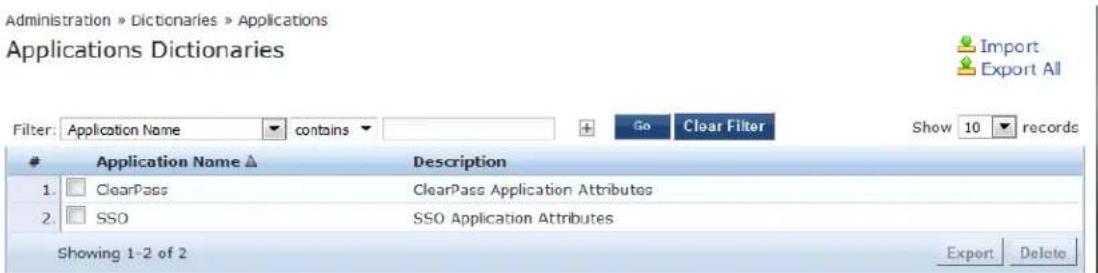
- To see the application attributes, click the name of an application.
The Application Attributes dialog box appears.
Figure 835: Application Attributes Dialog
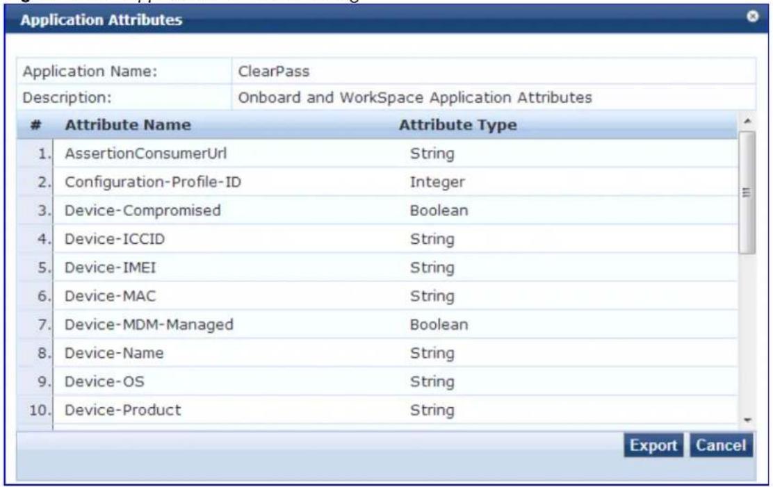
Deleting an Application Dictionary
In general, there is no need to delete an application dictionary. They have no effect on Policy Manager performance.
To delete an application dictionary:
- Navigate to Administration > Dictionaries > Applications.
- Click the check box next to an application name.
- Click Delete.
- Dell Networking W-ClearPass Policy Manager 6.6
- Copyright Information
- Open Source Code
- About W-ClearPass Policy Manager..21
- Services 35
- Monitoring 117
- Live Monitoring: OnGuard Activity 140
- Live Monitoring: Analysis and Trending 146
- Live Monitoring: System Monitor 147
- Profiler and Discovery 151
- Profiler and Discovery: Endpoint Profiler 152
- Profiler and Discovery: Network Discovery 153
- Audit Viewer 167
- Event Viewer 169
- Data Filters 172
- Restoring Blacklisted Users to the Network 177
- Authentication Methods and Sources 179
- Configuring Identity Settings 249
- Posture 279
- Configuring Enforcement Policies and Profiles 371
- Configuring Policy Simulation 425
- W-ClearPass Policy Manager Profile 447
- Network Access Devices 463
- Administration 479
- Cluster Upgrade/Update Tool 713
- Configuring Processing for Ingress Events 731
- OnGuard Dissolvable and Native Agents 739
- W-ClearPass Insight Reports 769
- Command Line Interface 821
- Cluster Commands 821
- Configure Commands 824
- Network Commands 830
- Miscellaneous Commands 836
- Rules Editing and Namespaces 919
- About the W-ClearPass Access Management System
- About This Guide
- Intended Audience
- Getting Started
- W-ClearPass Access Management System Overview
- About Policies, Profiles, and Services
- Role-Based and Device-Based Access
- Self-Service Capabilities
- Leveraging Contextual Data
- Third-Party Security and IT Systems
- Key Features
- Advanced Policy Management
- - Employee access
- • Device profiling
- - Access for unmanaged endpoints
- - Secure configuration of personal devices
- - Customizable visitor management
- • Device health checks
- W-ClearPass Specifications
- W-ClearPass Policy Manager
- Framework and Protocol Support
- Supported Identity Stores
- Using the Policy Manager Dashboard
- Accessing Configuration Information
- Introduction
- Start Here
- Services
- Authentication and Authorization
- Identity
- Posture
- Enforcement
- Network
- Policy Simulation
- Profile Settings
- Importing and Exporting Information
- Importing Information Into W-ClearPass
- Exporting Information From W-ClearPass
- Export Considerations
- Services Architecture and Flow
- Service Classification
- Service Flow Control
- Approaches to Creating a New Service
- Bottom-Up
- Top-Down
- Start Here: About Policy Manager Service Templates
- Creating Templates for W-ClearPass Services
- Service Templates Provided
- Service Templates Supported for High Capacity Guest Mode
- Viewing the List of Services
- Viewing Existing Services
- Adding and Removing Services
- Adding a New Service
- Creating a Service by Copying an Existing Service
- Modifying a Service
- Removing a Non-Default Service
- Reordering Services
- Reorder Services
- Click Save.
- Configuring Service Templates
- 802.1X Wired, 802.1X Wireless, and Dell 802.1X Wireless Service Template
- Adding a New Service for the Selected Service Template
- Deleting a Service
- Auto Sign-On Service Template
- Dell VPN Access with Posture Checks Service Template
- Certificate/Two-Factor Authentication for W-ClearPass Application Login Service Template
- Creating a New Web Login Page
- W-ClearPass Admin Access Service Template
- W-ClearPass Admin SSO Login (SAML SP Service) Service Template
- W-ClearPass Identity Provider (SAML IdP Service) Service Template
- Device MAC Authentication Service Template
- EDUROAM Service Template
- Encrypted Wireless Access via 802.1X Public PEAP Method Service Template
- Guest Access Service Template
- Guest Access Web Login Service Template
- Guest Authentication with MAC Caching Service Template
- Guest Social Media Authentication Service Template
- OAuth2 API User Access Service Template
- Onboard Service Template
- Configuring Policy Manager Services
- 802.1X Wired Service
- 802.1X Wired—Identity Only Service
- Dell 802.1X Wireless Service
- Service Configuration
- Authentication Configuration
- Authorization Configuration
- Roles Configuration
- Posture Configuration
- Enforcement Configuration
- Audit Configuration
- Profile Endpoints Configuration
- Accounting Proxy Configuration
- Summary Information
- 802.1X Wireless—Identity Only Service
- Cisco Web Authentication Proxy Service
- MAC Authentication Service
- RADIUS Authorization Service
- RADIUS Enforcement (Generic) Service
- RADIUS Proxy Service
- Dell W-Series Application Authentication Service
- Dell W-Series Application Authorization Service
- W-ClearPass OnConnect Enforcement Service
- Adding a W-ClearPass OnConnect Enforcement Service
- Associating the W-ClearPass OnConnect Service with an Enforcement Policy
- Event-Based Enforcement Service
- Associating the Service with an Enforcement Policy
- TACACS+ Enforcement Service
- Creating a TACACS+ Enforcement Service
- Configuring a TACACS+ Multi-Factor Authentication Service
- Web-Based Authentication Service
- About the Web-Based Authentication Service
- Selecting a Web-Based Authentication Service by the OS Name
- From the Service tab > Service Rule area, select Click to add.
- Specify the Host OS Architecture attribute as follows:
- Specify the Host OS Type attribute as follows:
- Specify the Host OS Name attribute as follows:
- Service Rule > Web-Based Authentication Host Attributes
- Web-based Health Check Only Service
- Web-Based Open Network Access Service
- Live Monitoring: Access Tracker
- About the Access Tracker
- Server Source Username Service Login Status Request Timestamp
- Customizing the Access Tracker
- Viewing Access Tracker Session Details
- RADIUS Session
- RADIUS > Summary Tab
- RADIUS > Input Tab
- WebAuth Session
- WebAuth Input Tab
- TACACS+ Session
- TACACS+ > Policies Tab
- Live Monitoring: Accounting
- Modifying the Accounting Page Parameters
- Specify the Edit Accounting Page parameters as described in Table 53:
- RADIUS Accounting Details > Summary Tab
- RADIUS Accounting Record Details > Auth Sessions Tab
- RADIUS Accounting Record Details > Utilization Tab
- RADIUS Accounting Record Details > Details Tab
- TACACS+ Accounting Record Details > Request Tab
- TACACS+ Accounting Record Details > Auth Sessions Tab
- TACACS+ Accounting Record Details > Details Tab
- Live Monitoring: OnGuard Activity
- About OnGuard Activity
- User Host MAC Host IP Host OS Status Date and Time Authentication Records
- Bouncing an Agent Using Non-SNMP
- Click Bounce.
- Bouncing a Client Using SNMP
- Requirements
- Bouncing a Client
- Broadcasting a Message to Active Endpoints
- Sending a Message to Selected Endpoints
- Live Monitoring: Analysis and Trending
- Live Monitoring: System Monitor
- System Monitor Page
- Process Monitor Page
- Network Monitor Page
- System Monitor
- ClearPass Monitor Page
- Profiler and Discovery
- Profiler and Discovery: Endpoint Profiler
- Profiler and Discovery: Network Discovery
- About Network Discovery
- Network Discovery High-Level Tasks
- Adding the Configurations to Query Seed Devices
- SNMP Credentials Configuration
- SSH Credentials Configuration
- WMI Credentials Configuration
- Click Add Configuration.
- Initiating a Network Discovery Scan
- About Auto-Refresh
- Seed Devices CPPM Server Start Time ▼ End Time Endpoints Devices Status Action
- Importing and Viewing Discovered Network Devices
- Importing Network Devices
- Click Import.
- Name ▲ IP or Subnet Address Description
- Viewing Details on a Discovered Device
- IP Address Name Port Device Description
- Viewing Discovered Endpoints
- Configuring Nmap-Based Endpoint Port Scans
- Audit Viewer
- Add Events
- Modify Events
- Remove Events
- Event Viewer
- About the Event Viewer
- Unsupported Admin Access Attempts Logged to the Event Viewer
- Source Level Category Action Timestamp V
- Creating an Event Viewer Report Using Default Values
- Creating an Event Viewer Report Using Custom Values
- Viewing Report Details
- Data Filters
- About Data Filters
- Preconfigured Data Filters
- Accessing the Data Filters Page
- Adding a Data Filter
- Rules Tab
- Restoring Blacklisted Users to the Network
- MAC Address User Name Authentication Source Bandwidth Limit Session Duration Timestamp △
- Supported Authentication Methods
- Tunneled EAP Authentication Methods
- Non-Tunneled Authentication Methods
- Authentication and Authorization Architecture and Flow
- Authentication Method
- Authentication Source
- Authorization Source
- Authentication and Authorization Flow of Control
- Configuring Authentication Methods for an Existing Service
- Adding and Configuring Authentication Methods
- Adding a New Authentication Method
- Name ▲ Type Description
- Modifying an Existing Authentication Method
- Authorize Authentication Method
- CHAP Authentication Method
- EAP-FAST Authentication Method
- General Tab
- Click Save.
- Inner Methods Tab
- PACs Tab
- PAC Provisioning Tab
- EAP-GTC Authentication Method
- EAP-MSCHAPv2
- EAP-PEAP
- EAP-PEAP-Public
- General
- Inner Methods
- EAP-PWD
- EAP-TLS
- EAP-TTLS
- MAC-AUTH Authentication Method
- MSCHAP
- PAP
- Adding and Configuring Authentication Sources
- Click Add.
- Generic LDAP and Active Directory
- General Configuration
- Primary Server Configuration
- Attributes Configuration
- Browse Configuration
- Filter Configuration
- Creating Filters
- Configuration Tab
- Modify Default Filters
- Generic SQL DB
- Primary Tab
- Attributes Tab
- Summary Tab
- HTTP
- Add More Filters
- Kerberos
- Okta
- RADIUS Server
- Authentication Sources
- Adding a Static Host List as an Authentication Source
- About Static Host Lists
- Click Save.
- Token Server
- Configuring Single Sign-On
- SAML Service Provider (SP) Configuration
- SAML Identity Provider (IdP) Configuration
- Managing Local Users
- Adding a Local User
- Modifying a Local User Account
- Importing and Exporting Local Users
- Setting Password Policy for Local Users
- Disabling Local User Accounts
- Adding and Modifying Endpoints
- Viewing the List of Authentication Endpoints
- Viewing Endpoint Authentication Details
- Performing Bulk Updates of Endpoint Attributes
- Triggering Actions to Be Performed on Endpoints
- Updating Device Fingerprints From a Hosted Portal
- Manually Adding an Endpoint
- Modifying an Endpoint
- Configuring the Attributes for the Selected Endpoint
- Viewing the Endpoint Fingerprint Details
- Managing Static Host Lists
- Internal Relational Database
- Role Statically Assigned
- Preconfigured Filter
- Adding a Static Host List
- Name ▲ Format Type Description
- Static Hosts Lists Configuration Summary
- Editing a Static Host List
- Importing and Exporting Static Host Lists
- Configuring a Role and Role-Mapping Policy
- Preconfigured Roles
- Identity Roles Architecture and Workflow
- A role can be:
- Adding and Modifying Roles
- Navigate to Configuration > Identity > Roles.
- Name ▲ Description
- Define the Add New Role parameters as described in the following table, then click Save.
- Adding and Modifying Role-Mapping Policies
- Adding a Role-Mapping Policy
- Name ▲ Description Default Role
- Mapping Rules
- Modifying a Role-Mapping Policy
- Posture Architecture and Flow
- Posture Policy
- Audit Servers
- Assessing Client Consistency
- Application Token
- System Token
- Unified Agent System Tray Status Icons
- About the Unified Agent
- Unified Agent System Tray Icons
- OnGuard-Only System Tray Icons
- Creating a New Posture Policy
- About W-ClearPass Posture Policies
- Configuring Posture Policy Agents and Hosts
- NAP Agent Posture Plug-ins
- OnGuard Agent Posture Plug-ins
- Configuring Posture Policy Plug-ins
- Configuring OnGuard Agent Plugins
- ClearPass Windows Universal System Health Validator > OnGuard Agent
- Defining the Service Group to Be Present
- To configure the Service Groups for Services to Run, click Add.
- Specify the Add Service Group to Be Present parameters as described in the following table:
- Specifying the Services to Be Present
- Click the Services to Be Present > Add button.
- Defining the Service Group to Be Absent
- Click Add.
- Processes
- Processes to be Present Parameters
- Processes to be Absent Parameters
- Registry Keys
- AntiVirus
- AntiSpyware
- Firewall
- Peer To Peer
- Patch Management
- Windows Hotfixes
- Configuring Windows Hotfixes Groups to Be Present
- USB Devices
- Virtual Machines
- Network Connections
- Disk Encryption
- Installed Applications
- Enabling Regular Expressions for a Windows Application
- File Check
- Defining the File Group to Be Present
- To open the File Group to be Present > Add page, click Add:
- When finished, click Save.
- Windows System Health Validator: OnGuard Agent
- Windows Security Health Validator: OnGuard Agent
- W-ClearPass Linux Universal System Health Validator Plugin
- W-ClearPass Macintosh OS X Universal System Health Validator: OnGuard Agent
- Virtual Machine
- Enabling Regular Expressions for a Mac OS X Application
- Configuring NAP Agent Plugins
- Windows System Health Validator: NAP Agent
- Windows Security Health Validator: NAP Agent
- Configuring Posture Policy Rules
- Configuring Posture for Services
- Configuring Audit Servers
- Audit Service Flow Control
- Default Audit Servers
- Adding Auditing to a Service
- Modifying Default Audit Servers
- Custom Audit Servers
- Adding a Nessus Audit Server
- Required Configuration Updates for External Nessus Servers
- Nessus Scan Profiles
- Adding an Nmap Audit Server
- Audit Tab
- Post-Audit Rules
- Configuring Enforcement Policies
- Configuring Enforcement Profile
- Adding an Enforcement Profile
- Modifying an Existing Enforcement Profile
- Agent Enforcement Profile
- Configuring Agent Enforcement Attributes
- Agent Script Enforcement Profile
- Mandatory Agent Script Attributes
- Optional Agent Script Attributes
- Configuring the Agent Script Enforcement Profile
- Configuring Agent Script Enforcement Attributes
- Viewing the Configuration Summary
- Dell Downloadable Role Enforcement Profile
- Profile Configuration
- Role Configuration Mode: Standard
- Captive Portal Profile
- Policer Profile
- QoS Profile
- VoIP Profile
- NetService Configuration
- NetDestination Configuration
- Role Configuration Mode: Advanced
- Dell RADIUS Enforcement Profile
- Cisco Downloadable ACL Enforcement Profile
- Cisco Web Authentication Enforcement Profile
- W-ClearPass Entity Update Enforcement Profile
- CLI-Based Enforcement Profile
- Filter ID Based Enforcement Profile
- Generic Application Enforcement Profile
- HTTP Based Enforcement Profile
- RADIUS Based Enforcement Profile
- RADIUS Change of Authorization (CoA) Profile
- Session Notification Enforcement Profile
- Session Restrictions Enforcement Profile
- Examples of Bandwidth-Check Enforcement Profile Configurations
- Examples of Session-Check Enforcement Profile Configurations
- SNMP-Based Enforcement Profile
- TACACS+ Based Enforcement Profile
- Services Configuration
- VLAN Enforcement Profile
- Active Directory Authentication Simulation
- Adding an Active Directory Simulation
- Viewing the Simulation Results
- Application Authentication Simulation
- Simulation Tab
- Results tab
- Audit Simulation
- Policy Simulation - audit
- Chained Simulation
- Enforcement Policy Simulation
- RADIUS Authentication Simulation
- Adding a RADIUS Authentication Simulation
- Setting the Attributes to Be Tested
- NAS Type: Aruba Wireless Controller
- NAS Type: Aruba Wired Switch Controller
- Attribute
- NAS Type: Cisco Wireless Switch
- Role Mapping Simulation
- Service Categorization Simulation
- Policy Simulation - service\_cat
- Import and Export Simulations
- Export Simulations
- W-ClearPass Profile Overview
- Enabling Endpoint Classification
- Configuring CoA for an Endpoint-Connected Device
- How W-ClearPass Profile Classifies Endpoints
- Stage 1: Deriving Device Profiles
- Stage 2: Refining Results
- Example
- Fingerprint Dictionaries
- Category △ Family Name
- Field Value
- Viewing Live Endpoint Information for a Specific Device
- About the Device Profile
- Endpoint Information Collectors
- DHCP Collector
- Sending DHCP Traffic to the W-ClearPass Server
- NetFlow Collector
- W-ClearPass Onboard Collector
- HTTP User-Agent Strings Collector
- MAC OUI Collector
- ActiveSync Plug-in Collector
- W-ClearPass OnGuard Agent
- SNMP Collector
- Setting SNMP Community Attributes
- Configuring the Device Info Poll Interval
- About the Subnet Scan Collector
- Configuring Subnet Scans
- Scheduling a Subnet Scan
- Initiating an On-Demand Subnet Scan
- SNMP Configuration for Wired Network Profiling
- Accessing SSH and WMI Configuration Information
- - SSH credentials
- • WMI credentials
- Adding and Modifying Network Devices
- Adding a Network Device
- Device Parameters
- SNMP Read Settings Parameters
- SNMP Write Settings Parameters
- CLI Settings Parameters
- Enabling W-ClearPass OnConnect Enforcement on a Network Device
- Querying and Selecting Port Names for OnConnect Enforcement
- Attributes Parameters
- Adding and Modifying Proxy Targets
- Adding a Proxy Target
- Adding and Modifying Device Groups
- Name △ Format Description
- Configuring the Ingress Event Sources
- When finished, click Add.
- - OnGuard
- • Insight Report Tool
- - Support
- - Cluster Update and Upgrade Tools
- • Ingress Events Processing
- W-ClearPass Guest Portal
- Navigate to the Administration > W-ClearPass Portal page.
- Managing Admin Users
- Changing the Administration Password
- User ID ▲ Name Privilege Level Status
- Adding an Admin User
- Disabling Admin User Accounts
- Managing Admin Privileges
- Overview
- Defining Custom Admin Privileges
- Click the Add link.
- Specify the parameters in the Basic Information tab as described in Table 272.
- Configuring Policy Manager Admin Privileges
- Configuring Insight Admin Privileges
- Creating Custom Administrator Privileges
- Administrator Privilege XML File Structure
- Administrator Privileges and Task IDs
- Sample Administrator Privilege XML File
- Read Only (R) Privileges to All Sections
- Read/Write Access
- Read/Write Permissions
- Server Configuration
- Server Name ▲ Management Port Data Port Zone Profile Cluster Sync Last Sync Time
- Editing Server Configuration Settings
- Cluster-Related Options
- Modifying W-ClearPass Server Settings
- Configuration Tasks for Disabled Nodes in a Cluster
- Synchronizing the Cluster Password
- Promoting a W-ClearPass Subscriber Node to Publisher
- Joining a W-ClearPass Server Back to the Cluster
- System Page
- Management Port Configuration
- Data/External Port Configuration
- DNS Settings Configuration
- Click Close.
- Join AD Domain
- Adding a Password Server
- Services Control Page
- Service Parameters Page
- Async Network Services Options
- W-ClearPass IPsec Service
- W-ClearPass Network Services Options
- W-ClearPass System Services Options
- Ingress Logger Service Ports
- Policy Server Options
- RADIUS Server Options
- Stats Collection Service Options
- System Monitoring Page
- Network Page
- Defining Application Access Control Restrictions
- Adding an SSH Public Key
- Creating GRE Tunnels
- Creating IPsec Tunnels
- Traffic Selectors
- Checking IPsec Tunnel Status
- Understanding the IPsec Tunnel Status Information
- Creating VLANs
- FIPS Page
- Important Points to Remember
- Server Configuration Cluster Options
- Synchronizing the Cluster Date and Time with the NTP Server
- Specifying the Time Zone on the Publisher
- Changing the Cluster-Wide Password
- Managing Policy Manager Zones
- About Policy Manager Zones
- Adding Policy Manager Zones
- Mapping Policy Manager Zones
- Configuring NetEvents Targets
- Click the NetEvents Targets link.
- Configuring Virtual IP Settings
- Clearing Machine Authentication Cache
- Making a Subscriber Node
- Cluster-Wide Parameters
- General Parameters
- Cleanup Intervals Parameters
- Notifications Parameters
- Standby Publisher Parameters
- Virtual IP Parameters
- Mode Parameters
- RADIUS Authentication Methods That Cannot Be Enabled
- Licensing Restrictions
- Cluster Restrictions
- Insight Requirement
- Service Templates Supported in High Capacity Guest Mode
- Service Types Supported in High Capacity Guest Mode
- Authentication Methods Supported in High Capacity Guest Mode
- Common Criteria Mode
- Database Parameters
- Profiler Parameters
- Collecting Logs
- Backing Up the Policy Manager Database
- Restoring Policy Manager Configuration Data
- Performing a System Cleanup
- Shutting Down or Rebooting the Server
- Dropping a Subscriber Node
- Log Configuration
- Service Log Configuration
- System Level Configuration
- Downloading Local Shared Folders
- Local Shared Folders
- License Management
- About License Usage Limits
- Managing Licenses
- License Summary Tab
- Licensing > Servers Tab
- Server IP Address Product License Type Native Number of Endpoints Duration Activation Status/License Added On
- Licensing > Applications Tab
- Product License Type Number of Endpoints Duration Activation Status License Added On
- Adding an Application License
- Click Add.
- Activating a Server License
- Online Activation
- Click Activate.
- Server IP Address Product License Type Native Number of Endpoints Duration Activation Status License Added On
- Offline Activation: Creating a Case to Receive the Activation Key
- Activating an Application License
- Product License Type Number of Endpoints Duration Activation Status License Added On
- Product License Type Number of Endpoints Duration Activation Status License Added On
- Updating a Server License
- Server IP Address Product License Type Native Number of Endpoints Duration Activation Status/License Added On
- Updating an Application License
- Product License Type Number of Endpoints Duration Activation Status/License Added On
- SNMP Trap Receivers
- SNMP Trap Receivers Main Page
- Host Address ▲ Description
- About the W-ClearPass SNMP Private MIB
- Adding an SNMP Trap Server
- Importing an SNMP Trap Server
- Exporting All SNMP Trap Servers
- Exporting an SNMP Trap Server
- Deleting an SNMP Trap Server
- Syslog Targets
- Syslog Targets Main Page
- Adding a Syslog Target
- Importing a Syslog Target
- Exporting All Syslog Target
- Exporting a Syslog Target
- Deleting a Syslog Target
- Syslog Export Filters
- About Syslog Export Filters
- Syslog Export Filters Page
- Name ▲ Description Export Template Status
- Adding a Syslog Export Filter
- Export Event Format Types—Examples
- Standard Event Format Type > Audit Events
- Standard Event Format Type > System Events
- Standard Event Format Type > Session Events
- CEF Event Format Type > Session Logs
- LEEF Event Format Type > Session Logs
- Filter and Columns Tab
- Insight Logs
- Session Logs
- Importing a Syslog Filter
- Exporting All Syslog Filter
- Exporting a Syslog Filter
- Deleting a Syslog Filter
- Messaging Setup
- Configuring Messaging
- Sending a Test Email Message
- Sending a Test SMS Message
- Endpoint Context Servers
- Endpoint Context Servers Page
- Server Name ▲ Server Type Status
- Adding an Endpoint Context Server
- Importing an Endpoint Context Server
- Exporting All Endpoint Context Servers
- Modifying an Endpoint Context Server
- Server Tab
- Actions Tab
- Polling an Endpoint Context Server
- Click Trigger Poll.
- Deleting an Endpoint Context Server
- Configuring Endpoint Context Server Actions
- Filtering an Endpoint Context Server Action Report
- Server Type ▲ Action Name HTTP Method Description
- Action Tab Parameters
- Header Tab Parameters
- Header Name Header Value
- Content Tab
- Attributes Tab Parameters
- Attribute Name Attribute Value
- Adding machine-os and host-type Endpoint Attributes
- Adding Vendor-Specific Endpoint Context Servers
- Adding an AirWatch Endpoint Context Server
- Adding an AirWave Endpoint Context Server
- Adding an Aruba Activate Endpoint Context Server
- Certificates Tab
- Adding a ClearPass Cloud Proxy Endpoint Context Server
- Adding a Google Admin Console Endpoint Context Server
- Adding a Generic HTTP Endpoint Context Server
- Integrating W-ClearPass with Infoblox
- Adding an Infoblox Endpoint Context Server
- Enter the following information:
- When finished defining the parameters in the Server page, click Save.
- Adding a Context Server Action to the Infoblox Server
- Navigate to Administration > Dictionaries > Context Server Actions.
- Server Type △ Action Name HTTP Method Description
- Attributes Sent to the Infoblox Server
- Click Cancel.
- Creating an Infoblox Enforcement Profile
- Tunnel-Private\_Group-Id
- Session-Timeout
- Tunnel-Type
- Termination-Action
- Creating an Infoblox Enforcement Policy
- Defining an Infoblox Service
- Authenticating External Devices Against the Infoblox Service
- Creating a Filter to Accept Information from the W-ClearPass Server
- Integrating W-ClearPass with Juniper Networks SRX
- Adding a Juniper Networks SRX Endpoint Context Server
- Adding a Context Server Action to the Juniper SRX Server
- Viewing or Modifying Juniper Networks SRX Endpoint Context Server Actions
- Creating a Juniper SRX Enforcement Profile
- Server Type
- Login Action
- Logout Action
- Creating a Juniper SRX Enforcement Policy
- Specify Conditions
- Defining a Juniper SRX Wireless Service
- Adding a JAMF Endpoint Context Server
- Adding a MaaS360 Endpoint Context Server
- Adding a MobileIron Endpoint Context Server
- Server Page
- Actions Page
- When satisfied with the Action settings, click Save.
- Adding a Palo Alto Networks Firewall Endpoint Context Server
- Using the ClearPass Configuration API to Load Endpoint Context Servers
- Adding a Palo Alto Networks Panorama Endpoint Context Server
- Adding an SAP Afaria Endpoint Context Server
- Adding a SOTI Endpoint Context Server
- Adding a XenMobile Endpoint Context Server
- File Backup Servers
- Server Certificates
- Server Certificate Page
- Server Certificate Type
- RADIUS Server Certificate
- HTTPS Server Certificate
- Creating a Certificate Signing Request
- Creating and Installing a Self-Signed Certificate
- Creating a Self-Signed Certificate
- Click Submit.
- Installing a Self-Signed Certificate
- Click Install.
- Importing a Server Certificate
- Exporting a Server Certificate
- Certificate Trust List
- Certificate Trust List Main Page
- Adding a Certificate
- Viewing a Certificate Detail
- Deleting a Certificate
- Certificate Revocation Lists
- About Certificate Revocation Lists
- Updating All Certificate Revocation Lists
- Adding a Certificate Revocation List
- Issuer DN ▲ Last Update Update Status
- Deleting a Certificate Revocation List
- RADIUS Dictionary
- Attribute Name ID Type In/Out
- Import RADIUS Dictionary
- TACACS+ Services Dictionary
- Device Fingerprints Dictionary
- Field Value
- Dictionary Attributes
- Name A Entity Data Type Is Mandatory Allow Multiple
- Adding a Dictionary Attribute
- Modifying Dictionary Attributes
- Importing Dictionary Attributes
- Exporting All Dictionary Attributes
- Exporting Selected Dictionary Attributes
- Software Updates and OnGuard Settings
- Software Updates
- About Software Updates
- Software Updates Page
- Install Update Dialog Box
- Webservice Operations
- Reinstalling a Patch
- Uninstalling a Skin
- OnGuard Settings and OnGuard Custom Web Pages
- About the OnGuard Custom Interface and the Remediation Process
- Enabling the Custom User Interface
- Creating Custom Web Pages
- Configuring OnGuard Settings
- Creating OnGuard Custom Web Pages
- HTML Content for OnGuard Custom Web Pages
- OnGuard Start Page
- OnGuard Progress Page
- OnGuard Finish Success Page
- OnGuard Finish Error Page
- HTML:
- OnGuard Finish Reboot Page
- Important Points
- OnGuard Custom Script Exit Codes
- Success Codes (0 to 63)
- Failure Codes (65 to 255)
- OnGuard Agent Codes (256 onwards):
- OnGuard Global Agent Settings
- About Global Agent Settings
- Global Agent Settings Parameters for OnGuard Agents
- Global Agent Settings: Run OnGuard As Parameter
- Limitations for the Run OnGuard As Parameter
- Using W-ClearPass Dictionaries
- About the Cluster Update Tool
- About the Cluster Update Feature
- Time Required for Subscriber Update
- Before Updating the Cluster
- Updating the Cluster
- Server Name Management IP Version Zone Insight(Size) Last Step Update Status View Logs
- □ Management IP Server Name Version Zone
- Viewing Update Status
- About the Cluster Upgrade Tool
- Cluster Upgrade Process Overview
- Before You Upgrade
- Installing the Cluster Upgrade Tool
- If the Publisher Is Not Set Up
- Launching the Cluster Upgrade Tool
- An Alternative Way to Open the Upgrade Tool
- Opening the Tool Via Your Web Browser
- Service Name Management IP Version Zone Insight(Blue) Last Step Upgrade Status View Logs
- Server Name Management IP Version Zone Insight(Size) Last Step Upgrade Status View Logs
- Upgrading the W-ClearPass Cluster
- Server Name Management IP Version Zone Insight(Size) Last Step Upgrade Status View Logs
- □ Management IP Server Name Version Zone
- Viewing Upgrade Status
- Steps in the Upgrade Tool's Automated Workflow
- Sample Times Required for Upgrade
- Troubleshooting Tips
- Enabling Ingress Event Dictionaries
- Vend
- Attribute Name Type
- Name ▲ Description IPAddress Type Vendor Enabled
- Configuring the Ingress Receiving Ports
- Configuring an Event-Based Enforcement Service
- Adding an Event-Based Enforcement Service
- Associating the Enforcement Service with an Enforcement Policy
- Enabling Ingress Events Processing
- Click the Enable Ingress Events Processing check box.
- To proceed with ingress events processing on this server, click Yes.
- Accessing the OnGuard Support Charts
- Upgrading From OnGuard Plugin Version 1.0 to 2.0
- Creating a New Enforcement Profile to Set the SDK Type
- Click Next.
- Modifying an Existing Enforcement Policy for OnGuard Plugin v2.0
- Change the SDK Type > Attribute Value to V4, then click Save.
- Creating a New Posture Policy for OnGuard Plugin v2.0 Agents
- Navigate to Configuration > Posture > Posture Policies.
- Click Next.
- Creating a WebAuth Service for OnGuard Plugin v2.0 Agents
- Native Agents Only Mode
- Configuring Workflow in Native Agents Only Mode
- End-to-End Flow in Native Agents Only Mode
- Auto-Login
- Troubleshooting
- Native Agents with Java Fallback Mode
- Configuring Native Agents with Java Fallback Mode
- End-to-End Flow in Native Agents with Java Fallback Mode
- Configuring Web Agent Flow - Java Only Mode
- Configuring Web Agent Flow in W-ClearPass Policy Manager
- Configuring Web Agent Flow in W-ClearPass Guest
- Native Dissolvable Agent Supported Operating Systems and Browsers
- OnGuard Dissolvable Agent Supported Browsers and Java Versions
- About W-ClearPass Insight
- Browsers Supported
- Enabling Insight and Specifying a Master Insight Node
- To enable Insight :
- Click Save.
- Launching Insight
- About the Insight Dashboard
- Dashboard Overview
- Adding a Report Widget to the Dashboard Landing Page
- Removing a Report Widget from the Dashboard Landing Page
- Creating a Report or Alert From the Dashboard
- Specifying the Date Range for Data Collection
- Authentication Dashboard
- Endpoints Dashboard
- Guest Dashboard
- Network Dashboard
- Posture Dashboard
- System Dashboard
- System Monitor Dashboard
- Searching the Insight Database
- About Insight Search
- Search Example
- Select the search object.
- Creating Alerts
- Creating New Alerts
- NAME TEMPLATE DESCRIPTION NOTIFICATION ENABLE MUTE
- Modifying the User Watchlist
- Default Watchlist Trigger Settings
- Adding or Removing Users from the Watchlist
- Adding a User to the Watchlist
- Removing a User from the Watchlist
- Creating Reports
- NAME DESCRIPTION TEMPLATE LAST RUN AT
- Run Reports Now or on a Specified Schedule
- Select Report Filters
- PDF, CSV, and HTML Report Formats Are Available
- Settings Configuration
- Report Filters Configuration
- Specifying the Logo and Branding
- Report Summary Page
- Configured Reports Page
- Viewing Reports
- Title
- Insight Report Categories Reference
- Authentication Category Reports
- Endpoint Category Reports
- Guest Authentication Category Reports
- Network Category Reports
- OnGuard Category Reports
- Onboard Category Report
- RADIUS Authentication Category Reports
- System Category Reports
- TACACS Category Reports
- Administration Operations
- Support Information
- File Transfer Settings Configuration
- Test
- Testing File Transfer Configuration
- Database Settings Configuration
- Managing Insight Admin Privileges
- Viewing the Default Insight Admin Privileges
- Defining Custom Insight Admin Privileges
- Specifying Insight Admin Privileges
- Insight UI Differences for Read-Only Users
- NAME DESCRIPTION TEMPLATE ENABLE
- Cluster Commands
- cluster drop-subscriber
- Syntax
- cluster list
- cluster make-publisher
- [appadmin]# cluster make-publisher
- cluster make-subscriber
- cluster reset-database
- cluster set-cluster-passwd
- cluster sync-cluster-passwd
- Configure Commands
- configure date
- Example 1
- Example 2
- configure dns
- Example 1: DNS Server
- Example 2: Primary and Secondary DNS Servers
- Example 3: Primary, Secondary, and Tertiary DNS Servers
- configure fips-mode
- configure hostname
- configure ip
- configure ip6
- configure mtu
- Example 3
- configure timezone
- Network Commands
- network ip6
- Syntax: network ip6 add
- Syntax: network ip6 del
- Syntax: network ip6 list
- Syntax: network ip6 reset
- network ip
- Syntax: network ip add
- Syntax: network ip del
- Syntax: network ip list
- Example: Adding a Custom Route
- Example: Listing All Custom Routes
- Syntax: network ip reset
- nslookup
- Syntax: network nslookup
- Example: Nslookup for IPv6 Address
- network ping6
- Syntax: network ping6
- network ping
- Syntax: network ping
- Example: Testing Reachability
- network reset
- Syntax: network reset
- network traceroute6
- Syntax: network traceroute6
- network traceroute
- Syntax: network traceroute
- Miscellaneous Commands
- ad auth
- ad netjoin
- ad netleave
- ad passwd-server
- ad testjoin
- alias
- backup
- dump certchain
- dump logs
- dump servercert
- exit
- help
- krb auth
- krb list
- Idapsearch
- quit
- restore
- Syntax 1
- Syntax 2
- Syntax 3
- Service Commands
- Show Commands
- show all-timezones
- show date
- show dns
- show domain
- show fipsmode
- show hostname
- show ip
- show license
- show ntp
- show sysinfo
- show timezone
- show version
- SSH Timed Account Lockout
- Node-Specific
- Account Lockout Persistence
- SSH Account Lockout Configuration
- SSH Lockout
- SSH Lockout Count
- SSH Lockout Duration
- SSH Lockout Reset
- SSH Unlock
- Show SSH
- SSH Account Lockout Alerts
- SSH Account Lockout Behavior
- System Commands
- system apps-access-reset
- system boot-image
- system cleanup
- system create-api-client
- system gen-recovery-key
- system gen-support-key
- system install-license
- system morph-vm
- system refresh-license
- system reset-server-certificate
- system restart
- system shutdown
- system sso-reset
- system start-rasession
- system status-rasession
- system terminate-rasession
- system update
- system upgrade
- Example 1: Upgrading from a Linux Server
- Example 2: Upgrading from a Web Server
- Example 3: Performing an Offline Upgrade
- W-ClearPass SNMP Private MIB
- System MIB Entries
- RADIUS Server MIB Entries
- RadiusServerTableEntry
- RadiusServerAuthTableEntry
- Policy Server MIB Entries
- PolicyServerTableEntry
- PolicyServerProtoTableEntry
- PolicyServerAutzTableEntry
- Web Authentication Server MIB Entries
- TACACS+ Server MIB Entries
- TacacsAuthTableEntry
- TacacsAutzTableEntry
- Network Traffic MIB Entries
- W-ClearPass SNMP Traps and OIDs
- W-ClearPass SNMP Traps
- SNMP Trap Details
- SNMP Daemon Traps
- Network Interface up and Down Events
- W-ClearPass Processes Stop and Start Events
- Disk Space Threshold Traps
- Disk Utilization Threshold Exceed Events
- Process Status Traps
- RADIUS server start SNMP trap
- Admin Server start SNMP trap
- System Auxiliary server stop SNMP trap
- Policy server stop SNMP trap
- Policy server start SNMP trap
- Async DB write service stop SNMP trap
- Async DB write service start SNMP trap
- DB replication service stop SNMP trap
- DB replication service start SNMP trap
- Async netd service start SNMP trap
- Multi-master Cache service stop SNMP trap
- AirGroup Notification service stop SNMP trap
- Micros Fidelio FIAS service start SNMP trap
- TACACS server stop SNMP trap
- TACACS server start SNMP trap
- Virtual IP service start SNMP trap
- Stats Aggregation service stop SNMP trap
- stats Aggregation service start SNMP trap
- CPU Load Average Exceed Events for 1, 5, and 15 Minute Thresholds
- CPU Load Average Traps
- Important System Events
- Admin User Interface Events
- Critical Events
- Info Events
- Admin Server Events
- Async Service Events
- W-ClearPass/Domain Controller Events
- W-ClearPass System Configuration Events
- W-ClearPass Update Events
- Cluster Events
- Command Line Events
- Database Replication Services Events
- Licensing Events
- Policy Server Events
- RADIUS/TACACS+ Server Events
- Service Names
- SNMP Events
- Support Shell Events
- System Auxiliary Service Events
- System Monitor Events
- Error Codes
- 802.1X Wireless Use Case
- Configuring a Service
- Creating a New Role Mapping Policy
- Web Based Authentication Use Case
- Create an Enforcement Policy.
- Save the Service.
- MAC Authentication Use Case
- Configuring the Service
- TACACS+ Use Case
- Single Port Use Case
- Namespaces
- Application Namespace
- Audit Namespaces
- Authentication Namespaces
- Authentication Namespace Editing Context
- Authorization Namespaces
- Authorization editing context
- AD Instance Namespace
- Authorization
- LDAP Instance Namespace
- RSAToken Instance Namespace
- Sources
- SQL Instance Namespace
- Certificate Namespaces
- Certificate Namespace Editing Context
- Connection Namespaces
- Connection Namespace Editing Contexts
- Date Namespaces
- Date Namespace Editing Contexts
- Device Namespaces
- Endpoint Namespaces
- Guest User Namespaces
- Host Namespaces
- Local User Namespaces
- Posture Namespaces
- Posture Namespace Editing Context
- RADIUS Namespaces
- RADIUS Namespace Editing Contexts
- TACACS Namespaces
- Tips Namespaces
- Role
- Tips Namespace Editing Context
- Variables
- Operators
- Applications Dictionaries
- Viewing an Application Dictionary
- Application Name ▲ Description
- Attribute Name Attribute Type
- Deleting an Application Dictionary
Brand : DELL
Model : W-ClearPass
Category : Uncategorized