
KVT-817DVD - Car stereo KENWOOD - Free user manual and instructions
Find the device manual for free KVT-817DVD KENWOOD in PDF.
| Product Type | Car Stereo with DVD Screen |
| Brand | KENWOOD |
| Model | KVT-817DVD |
| Power Supply | 12 V DC (car battery) |
| Output Power | 50 W x 4 (max) |
| Supported Formats | DVD, CD, MP3, WMA, JPEG |
| Screen | 7-inch Color LCD Touchscreen |
| Tuner | AM/FM |
| Inputs | Front/Rear AV, rear camera, optical (changer) |
| Outputs | Front/Rear pre-outs, subwoofer (mono), center, video |
| Connectivity | Wired remote, steering wheel control compatible |
| Installation | 2 DIN mount, max angle 30° |
| Safety | Parking brake detection, video cut while driving |
| Dimensions (approx.) | 178 x 100 x 160 mm |
| Weight (approx.) | 1.5 kg |
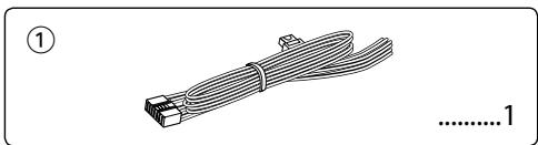
| Included Accessories | Remote control, mounting kit, optical cable, wiring harness |
| Maintenance | Clean with a soft dry cloth |
| Repairability | Replaceable fuse, reset button |
Frequently Asked Questions - KVT-817DVD KENWOOD
User questions about KVT-817DVD KENWOOD
0 question about this device. Answer the ones you know or ask your own.
Ask a new question about this device
Download the instructions for your Car stereo in PDF format for free! Find your manual KVT-817DVD - KENWOOD and take your electronic device back in hand. On this page are published all the documents necessary for the use of your device. KVT-817DVD by KENWOOD.
USER MANUAL KVT-817DVD KENWOOD
MANUEL D'INSTALLATION
MONITOR CON RECEPTOR DVD
natural_image
Illustration of a bundled cable with connectors, labeled with number 1 (no text or symbols on the cable itself)
natural_image
Simple line drawing of a metal bracket with mounting holes and slots, no text or symbols present
natural_image
Illustration of two cables with connectors, no text or symbols present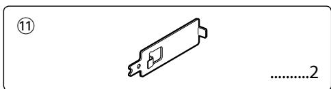
natural_image
Coiled cable with two connectors, no text or symbols visible
natural_image
Simple line drawing of a screw with no text or symbols
natural_image
Pure mechanical component diagram without any text, numbers, or symbols
natural_image
Simple line drawing of a rope tied with a clip, no text or symbols present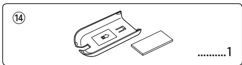
natural_image
Line drawing of a battery pack and its internal components (no text or symbols)
natural_image
Simple line drawing of a rectangular electronic component with no text or symbols
natural_image
Illustration of a cable with two connectors and a numbered label (15) at the top left, no text or symbols on the main subject.
natural_image
Technical line drawing of a mechanical tool or bracket with no visible text or symbols

natural_image
Simple line drawing of a bolt with a flange and nut, no text or symbols present
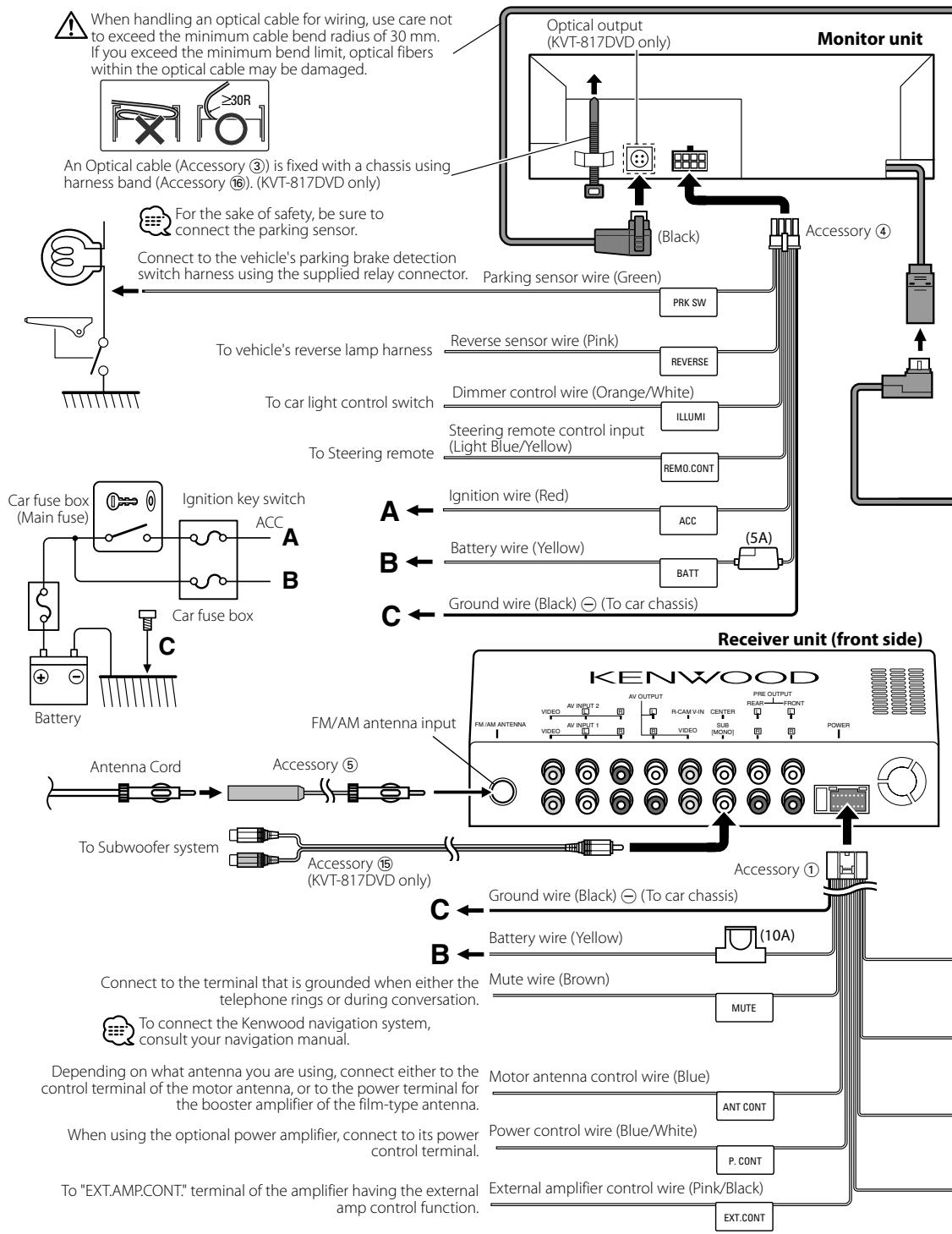
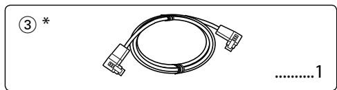
* KVT-817DVD only
Installation Procedure
- To prevent a short circuit, remove the key from the ignition and disconnect the battery.
- Make the proper input and output wire connections for each unit.
- Connect the speaker wires of the wiring harness.
- Connect the wiring harness wires in the following order: ground, battery, ignition.
- Connect the wiring harness connector to the unit.
- Install the unit in your car.
- Reconnect the battery.
- Press the reset button.
WARNING
- If you connect the ignition wire (red) and the battery wire (yellow) to the car chassis (ground), you may cause a short circuit, that in turn may start a fire. Always connect those wires to the power source running through the fuse box.
- Do not cut out the fuse from the ignition wire (red) and the battery wire (yellow). The power supply must be connected to the wires via the fuse.
CAUTION
- If the power is not turned ON (or it is ON, but will be OFF immediately), the speaker wire may have a short-circuit or touched the chassis of the vehicle and the protection function may have been activated. Therefore, the speaker wire should be checked.
- If your car's ignition does not have an ACC position, connect the ignition wires to a power source that can be turned on and off with the ignition key. If you connect the ignition wire to a power source with a constant voltage supply, as with battery wires, the battery may die.
- If the console has a lid, make sure to install the unit so that the faceplate will not hit the lid when closing and opening.
- If the fuse blows, first make sure the wires aren't touching to cause a short circuit, then replace the old fuse with one with the same rating.
- Insulate unconnected wires with vinyl tape or other similar material. To prevent a short circuit, do not remove the caps on the ends of the unconnected wires or the terminals.
- Connect the speaker wires correctly to the terminals to which they correspond. The unit may be damaged or fail to work if you share the wires or ground them to any metal part in the car.
- When only two speakers are being connected to the system, connect the connectors either to both the front output terminals or to both the rear output terminals (do not mix front and rear). For example, if you connect the connector of the left speaker to a front output terminal, do not connect the connector to a rear output terminal.
• After the unit is installed, check whether the brake lamps, blinkers, wipers, etc. on the car are working properly. - Mount the unit so that the mounting angle is 30^ or less.
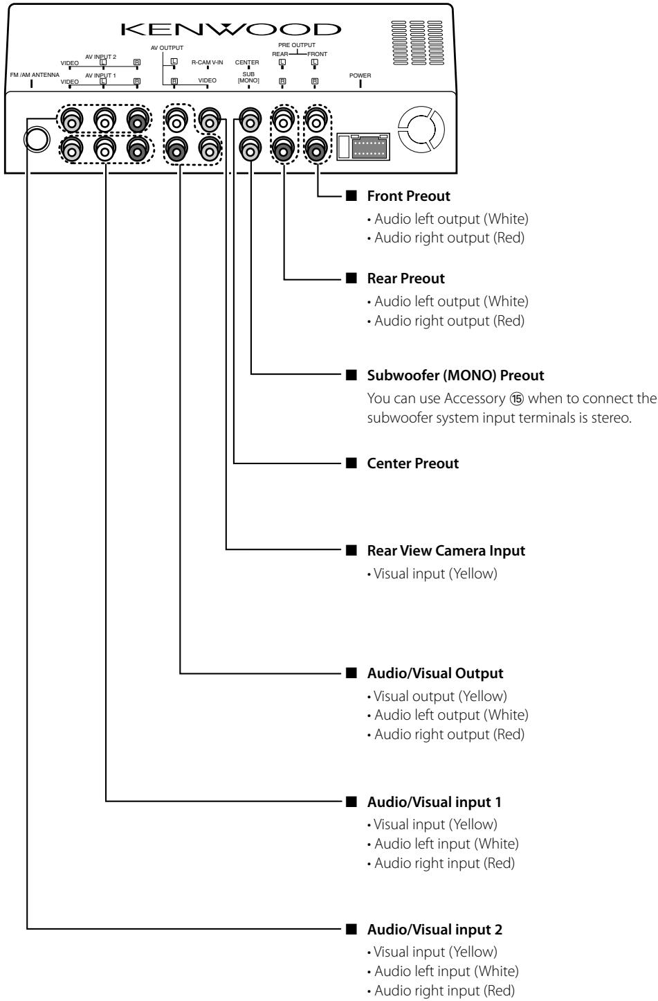
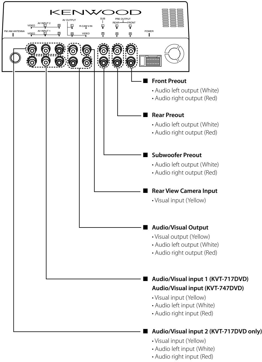
Connection
flowchart
graph TD
    A["Monitor unit"] --> B["An Optical cable (Accessory 3) is fixed with a chassis using harness band (Accessory 16). (KVT-817DVD only)"]
    B --> C["For the sake of safety, be sure to connect the parking sensor."]
    C --> D["Connect to the vehicle's parking brake detection switch harness using the supplied relay connector."]
    D --> E["To vehicle's reverse lamp harness"]
    E --> F["To car light control switch"]
    F --> G["Steering remote control input (Light Blue/Yellow)"]
    G --> H["Reversible sensor wire (Pink)"]
    H --> I["Dimmer control wire (Orange/White)"]
    I --> J["ILLUMI"]
    J --> K["REMO.CONT"]
    K --> L["Ignition wire (Red)"]
    L --> M["ACC"]
    M --> N["Battery wire (Yellow)"]
    N --> O["BATT"]
    O --> P["(5A)"]
    P --> Q["Ground wire (Black) ⊖ (To car chassis)"]
    Q --> R["Receiver unit (front side)"]
    R --> S["KENWOOD"]
    S --> T["FM/AM antenna input"]
    T --> U["Antenna Cord"]
    U --> V["Accessory ⑤"]
    V --> W["To Subwoofer system"]
    W --> X["Accessory ⑮ (KVT-817DVD only)"]
    X --> Y["Ground wire (Black) ⊖ (To car chassis)"]
    Y --> Z["Battery wire (Yellow)"]
    Z --> AA["(10A)"]
    AA --> AB["Mute wire (Brown)"]
    AB --> AC["MUTE"]
    AC --> AD["Motor antenna control wire (Blue)"]
    AD --> AE["ANT CONT"]
    AE --> AF["P. CONT"]
    AF --> AG["External amplifier control wire (Pink/Black)"]
    AG --> AH["EXT.CONT"]
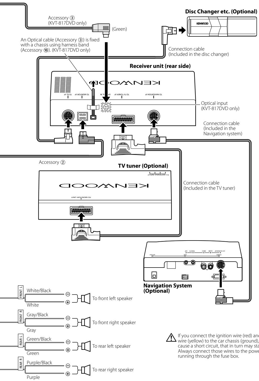
flowchart
graph TD
    A["Accessory ③ (KVT-817DVD only)"] -->|Green| B["Receiver unit (rear side)"]
    C["An Optical cable (Accessory ③) is fixed with a chassis using harness band (Accessory ⑥). (KVT-817DVD only)"] --> B
    D["Connection cable (Included in the disc changer)"] --> B
    E["KDOWN3K"] --> B
    F["Utility input (KVT-817DVD only)"] --> B
    G["Connection cable (Included in the Navigation system)"] --> B
    H["TV tuner (Optional)"] --> I["Navigation System (Optional)"]
    J["Accessory ②"] --> K["To front left speaker"]
    L["Connection cable (Included in the TV tuner)"] --> K
    M["White/Black"] --> N["To front left speaker"]
    O["White"] --> N
    P["Gray/Black"] --> Q["To front right speaker"]
    R["Gray"] --> Q
    S["Green/Black"] --> T["To rear left speaker"]
    U["Green"] --> T
    V["Purple/Black"] --> W["To rear right speaker"]
    X["Purple"] --> W
    Y["If you connect the ignition wire (red) and wire (yellow) to the car chassis (ground), cause a short circuit, that in turn may start. Always connect those wires to the power running through the fuse box."] --> Z["Navigation System (Optional)"]

If you connect the ignition wire (red) and the battery wire (yellow) to the car chassis (ground), you may cause a short circuit, that in turn may start a fire. Always connect those wires to the power source running through the fuse box.
Installation for Monitor Unit

Make sure that the unit is installed securely in place. If the unit is unstable, it may malfunction (eg, the sound may skip).
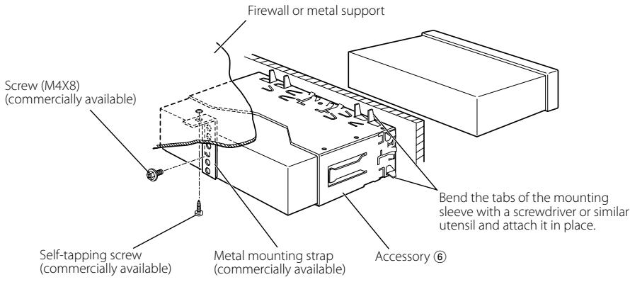
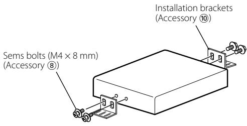
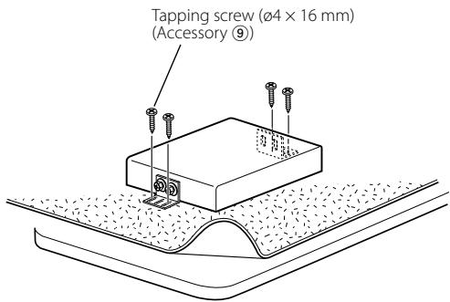
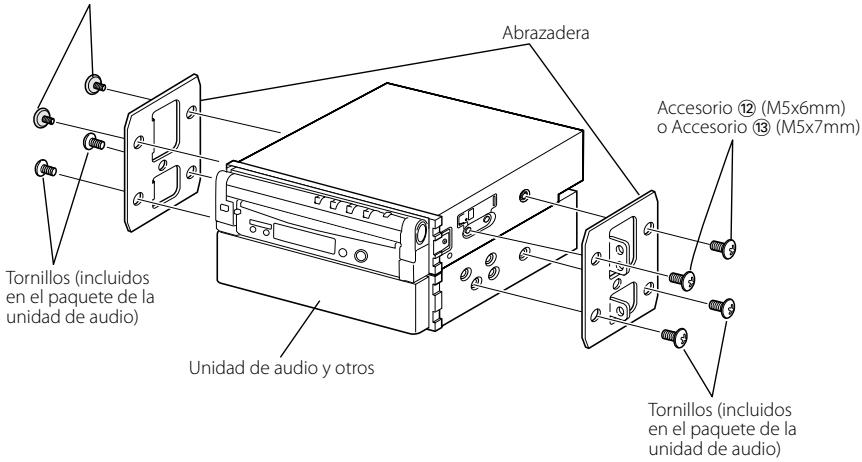
Installation for Receiver unit
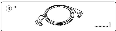
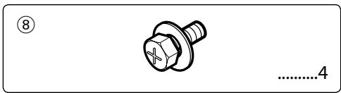
- Attach the installation brackets ⑩ to the sides of the hideaway unit using the sems bolts ⑧.
- Use the tapping screw ⑨ to secure the hideaway unit to the audio board.
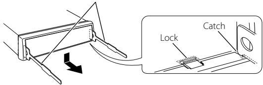
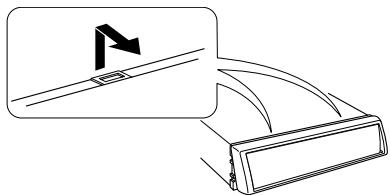
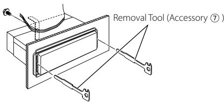
■ Removing the Hard Rubber Frame (escutcheon)
- Engage the catch pins on the removal tool ⑦ and remove the two locks on the lower level. Lower the frame and pull it forward as shown in the figure.
- When the lower level is removed, remove the upper two locations.
Removal Tool (Accessory ⑦)
natural_image
Diagram showing a mechanical component with an inset view of a bracket and a flag symbol (no text or labels)■ Removing the Unit
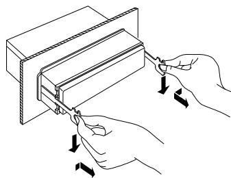
- Remove the hard rubber frame by referring to the removal procedure in the section
. - Remove the Hex-head screw with integral washer (M4 × 8) on the back panel.
- Insert the two removal tools ⑦ deeply into the slots on each side, as shown.
- Lower the removal tool toward the bottom, and pull out the unit halfway while pressing towards the inside.

Be careful to avoid injury from the catch pins on the removal tool.
- Pull the unit all the way out with your hands, being careful not to drop it.
natural_image
Illustration of hands using a tool to adjust or install a component, no text or symbols present
natural_image
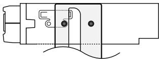
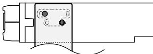
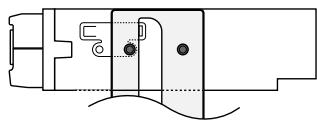
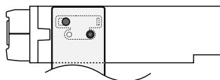
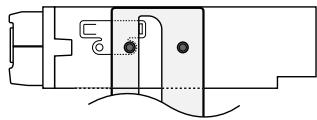
Technical line drawing of a mechanical assembly with a hand holding a bracket (no text or symbols)■ Installation on Toyota, Nissan or Mitsubishi Car using Brackets at Holes shown by "●"
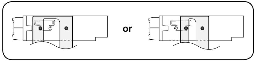
■ Installation on Toyota Car using Brackets at Holes shown by "●"
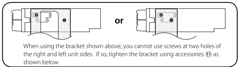
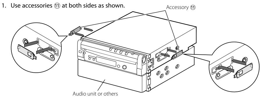
2. Mount the bracket at each side.
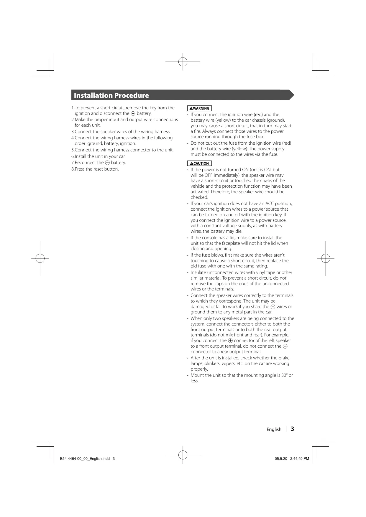
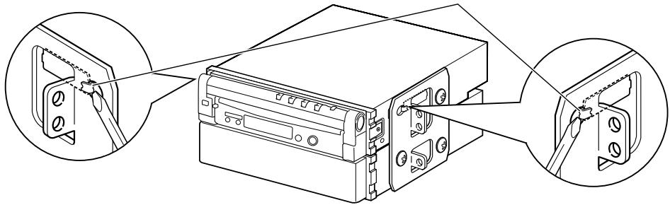
3. Bend each end of accessory ⑪ to fix the bracket.
Use a flat-blade screwdriver or pliers, and bend each accessory tab into the hole of installation bracket to fix the bracket.
natural_image
Technical line drawing of a mechanical device with three circular insets showing close-ups of components (no text or symbols)Installation of Remote control unit
■ Install the remote control unit holder (Accessory ⑭).
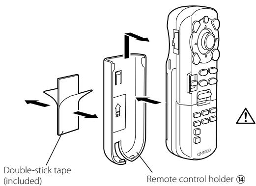

To prevent the Remote control unit from dropping down under your foot, install it using the Remote control unit holder. If the Remote control unit drops down under driving pedals, it will interfere with your driving and may result in a traffic accident.
Accessoires
natural_image
Illustration of a bundled cable with connectors, no text or symbols present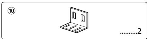
natural_image
Simple line drawing of a metal bracket with mounting holes and slots, no text or symbols present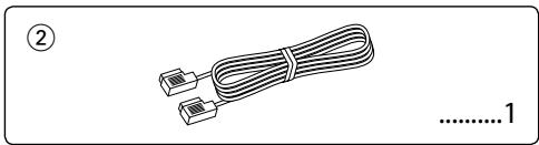
natural_image
Illustration of two cables with connectors, no text or symbols present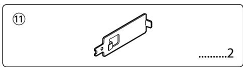
natural_image
Coiled cable with connectors, no text or symbols visible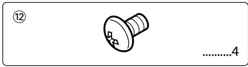
natural_image
Simple line drawing of a screw with a circular head and threaded shaft, no text or symbols present.
natural_image
Pure mechanical component diagram without any text, numbers, or symbols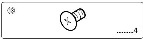

natural_image
Simple line drawing of a rope tied with a string, no text or symbols present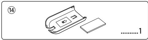
natural_image
Simple line drawing of a device with a handle and base, no text or symbols present
natural_image
Simple line drawing of a rectangular electronic component with no text or symbols
natural_image
Illustration of a coiled cable with connectors, no text or symbols present
natural_image
Simple line drawing of a tool handle with no text or symbols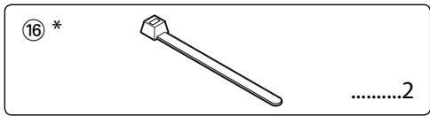

natural_image
Simple line drawing of a bolt with a flange and threaded head (no text or symbols)
natural_image
Pure mechanical diagram showing a lever mechanism without any text, numbers, or symbols
natural_image
Grid of circular target icons with varying shades of gray, no text or symbols presentAccessoire ①


natural_image
Diagram showing a mechanical component with an inset view of a bracket and a flag symbol (no text or labels)natural_image
Illustration of hands using a tool to adjust or install a component, no text or symbols present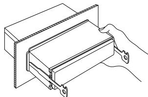
natural_image
Technical line drawing of a mechanical assembly with a hand holding a bracket (no text or symbols)natural_image
Pure mechanical component diagram without any text, numbers, or symbolsou
natural_image
Pure mechanical component diagram without any text, numbers, or symbols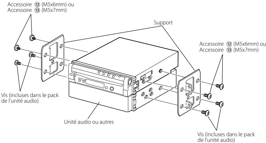
natural_image
Pure mechanical component diagram without any text, numbers, or symbolsou
natural_image
Pure mechanical component diagram without any text, numbers, or symbolsnatural_image
Illustration of a bundled cable with connectors, no text or symbols present
natural_image
Simple line drawing of a metal bracket with mounting holes, no text or symbols present
natural_image
Illustration of two cables with connectors, no text or symbols present

natural_image
Coiled cable with two connectors, no text or symbols visible
natural_image
Simple line drawing of a screw with no text or symbols
natural_image
Pure mechanical component diagram without any text, numbers, or symbols

natural_image
Simple line drawing of a rope tied with a clip, no text or symbols present
natural_image
Line drawing of a battery pack and its internal components (no text or symbols)
natural_image
Simple line drawing of a rectangular electronic component with no text or symbols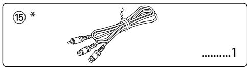
natural_image
Illustration of a cable with two connectors and a numbered label (15) at the top left, no text or symbols on the main subject.
natural_image
Technical line drawing of a mechanical tool or bracket with no visible text or symbols

natural_image
Simple line drawing of a bolt with a flange and nut, no text or symbols present
natural_image
Pure mechanical diagram showing a lever and pivot point without any text, numbers, or symbols
natural_image
Diagram showing a mechanical component with an inset view of a bracket and a flag symbol (no text or labels)natural_image
Illustration of hands using a tool to adjust or install a component, no text or symbols present
natural_image
Technical line drawing of a mechanical assembly with a hand holding a bracket (no text or symbols)natural_image
Pure mechanical component diagram without any text, numbers, or symbols0
natural_image
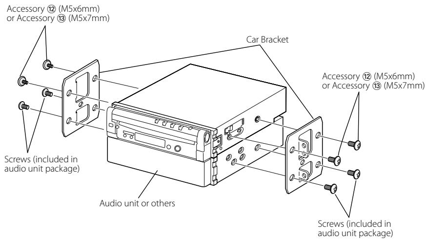
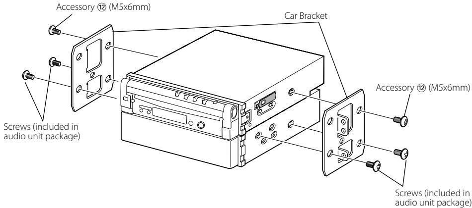
Pure mechanical assembly diagram without any text, numbers, or symbolsAccesorio ⑫ (M5x6mm)
o Accesorio ⑬ (M5x7mm)
natural_image
Pure mechanical component diagram without any text, numbers, or symbols0
natural_image
Pure mechanical component diagram without any text, numbers, or symbolsnatural_image
Technical line drawing of a mechanical device with three circular insets showing close-ups of components (no text or symbols)natural_image
Illustration of a bundled cable with connectors, labeled with number 1 (no text or symbols on the cable itself)
natural_image
Simple line drawing of a metal bracket with mounting holes, no text or symbols present
natural_image
Illustration of two cables with connectors, no text or symbols present

natural_image
Coiled cable with two connectors, no text or symbols visible
natural_image
Simple line drawing of a screw with no text or symbols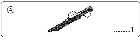
natural_image
Pure mechanical component diagram without any text, numbers, or symbols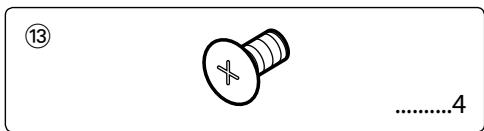

natural_image
Simple line drawing of a rope tied with a clip, no text or symbols present
natural_image
Line drawing of a battery pack and its internal components (no text or symbols)
natural_image
Simple line drawing of a rectangular electronic component with no text or symbols
natural_image
Illustration of a cable with two connectors and a numbered label (15) at the top left, no text or symbols on the main subject.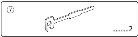
natural_image
Technical line drawing of a mechanical tool or bracket with no visible text or symbols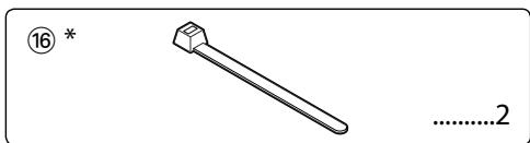
natural_image
Simple line drawing of a bolt with a flange and nut, no text or symbols present
* Apenas KVT-817DVD

natural_image
Simple line drawing of a mechanical lever system with no text or symbolsnatural_image
Diagram showing a mechanical component with an inset view of a bracket and a flag symbol (no text or labels)Retirar o aparelho
natural_image
Illustration of hands using a tool to adjust or install a component, no text or symbols present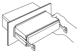
natural_image
Technical line drawing of a mechanical assembly with a hand holding a bracket (no text or symbols)natural_image
Pure mechanical component diagram without any text, numbers, or symbolsou
natural_image
Pure mechanical assembly diagram without any text, numbers, or symbols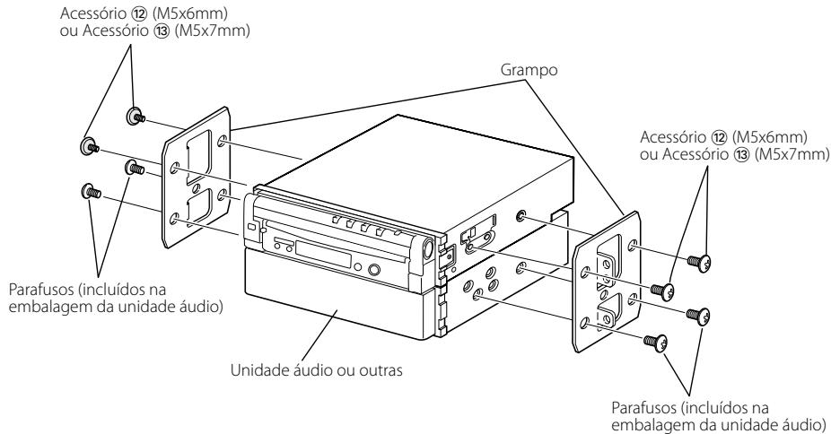
natural_image
Pure mechanical component diagram without any text, numbers, or symbolsor
