
CS0014 - Industrial electronic module IFM - Free user manual and instructions
Find the device manual for free CS0014 IFM in PDF.


| Product Type | Display and input module for controllers (DDM 100) |
| Brand | IFM |
| Model | CS0014 |
| Display | Backlit LCD, 2 lines x 16 characters each, freely programmable |
| Operating Voltage | 10...30 V DC (SELV) |
| Current Consumption | 100 mA (max. 1 A with fuse) |
| Protection Rating | IP64 / III |
| Operating Temperature | 0...+50 °C |
| Dimensions (W x H x D) | 190 x 90 mm; height: 32 mm (wall mount), 7 mm (panel mount); depth: 25 mm (panel mount) |
| Number of Keys | 9 total (3 freely assignable function keys, 6 with fixed functions) |
| LEDs | 3 yellow, freely programmable |
| Interface | CAN (2.0 A/B) at 125 kBaud |
| CAN Identifiers | Receive: 7F0 HEX...7F1 HEX; Send: 7F8 HEX...7FA HEX |
| Connections | 5 WAGO cage-clamp terminals: CAN_H, CAN_L, GND (x2), +24V |
| Mounting | Control cabinet or wall mounting |
| Programming | Via ifm controller using IEC 1131 languages (e.g., FBD, ST) |
| Text Screens | Up to 16 active, each with 2 lines of 16 characters; prioritizable |
| Process Data Integration | Up to 2 values per line, editable with limits; formats: signed, unsigned, hex |
| Cleaning | Use a soft cloth with polyester-safe cleaning agent |
| Declaration of Conformity | CE mark based on EMC directive 89/336/EEC and low voltage directive |
Frequently Asked Questions - CS0014 IFM
User questions about CS0014 IFM
0 question about this device. Answer the ones you know or ask your own.
Ask a new question about this device
Download the instructions for your Industrial electronic module in PDF format for free! Find your manual CS0014 - IFM and take your electronic device back in hand. On this page are published all the documents necessary for the use of your device. CS0014 by IFM.
USER MANUAL CS0014 IFM
2. Montage

$$ \% n X = H E X = 0 \dots F F F F $$
n = 0 ... 5; optional verwendbar:
$$ \% n X = H E X = 0 \dots F F F F $$
n = 0 ... 5; optional verwendbar:
- Functions of the DDM 100 ..... 21
- Mounting 22
2.1 Control cabinet mounting 22
2.2 Wall mounting 23
- Programming....24
3.1 Programming with data transfer ..... 24
Description 24
Programming example in FBD 26
3.2 Programming with address transfer....27
Description 27
Programming example in ST 28
3.3 Program function keys and LEDs 29
3.4 Enable the communication
between the controller and the DDM ..... 29
- Operation 30
4.1 Normal operation....30
4.2 Parameter setting mode....32
Activate parameter setting mode 32
Language selection 32
Set display time 33
Set flashing time 33
Set CAN identifier 33
Set bit rate 33
4.3 Presentation of the keys 34
- Trouble shooting 35
- Cleaning 34
- Technical data 36
- Declaration of conformity 37
1. Functions of the DDM 100
The data dialogue module DDM 100 with CAN interface is a display and input module for ifm control systems in CAN technology.
The DDM has the following features and functions:
Mounting
• Control cabinet or wall mounting
- Small compact housing with a height of only 32mm
- Mounting of the unit can be carried out before programming
Programming
- Create and control the display of the text screens for the DDM within the controller program
- Unlimited number of programmed display text screens
- 16 text screens active at any one time with 16 characters per line (max. 2 lines) for the backlit text display
• Prioritising of up to 16 active text screens - Display texts with integrated process data, if necessary
- Integrated process data can be edited
• Free assignment of the 3 function keys
• Free assignment of the 3 LEDs

2. Mounting

C-MOS components are damaged by electrostatic discharge.
Before mounting the front panel, touch the grounded part to reduce the electrostatic charging.

2.1 Control cabinet mounting
- By means of the supplied template prepare a cut-out and drill 4 holes for fixing (maximum thickness of the front panel = 2.5mm).
- Insert the housing lower part (3) into the cut-out from the inside of the control cabinet.
- Slip the supplied spring clamps (8) into the holders to the right and left in the housing lower part from the outside of the control cabinet and fasten the housing lower part in the cut-out.
- Knock out available for PG 16 cable gland (6).
- Insert the supplied PG16 cable gland.
- Insert the cable.
- Make the connections as per the label (7) in the housing lower part (3). The unit must be connected by qualified personnel.
- Place the housing upper part (1) onto the housing lower part (3) in such a way that the contact pins (2) of the housing upper part engage with the terminals (5) in the housing lower part.
- Screw the housing upper part with the housing lower part.
2.2 Wall mounting
See the mounting sketch on page 22.
- Knock out available for PG 16 cable gland (6), or make a cable gland hole in the lower side wall within the connection chamber (see supplied template) and cut a suitable PG7 thread.
- Insert the supplied PG16 cable gland, if necessary.
- Insert the cable.
- Fasten the housing lower part with four screws or similar elements (4) to the wall.
- Make the connections as per the label (7) in the housing lower part (3). The unit must be connected by qualified personnel.
- Place the housing upper part (1) onto the housing lower part (3) in such a way that the contact pins (2) of the housing upper part engage with the terminals (5) in the housing lower part.
- Screw the housing upper part with the housing lower part.
3. Programming
To integrate the DDM 100 in an ifm controller you have to program the following in the user program of the controller:
• Text screens to be displayed
- Display priority of the text screens
- Process data to be integrated into the texts, if necessary
- If necessary, enable the integrated process data for editing
- Assignment of the function keys
- Assignment of the LEDs
- Enable the communication between the controller and the DDM by means of the system variable TEXT_MODE.
Write the user program of the controller in the ecolog 100 ^plus . You can use the programming languages to IEC 1131. For the description of how to program the controller please refer to the ecolog 100 ^plus manual.
There are two strategies to program the texts for the DDM:
• Data transfer (see chapter 3.1)
- Address transfer (see chapter 3.2, recommended for run time critical applications and for applications with many texts)
3.1 Programming with data transfer
Description
In the device-specific library of the controller you find the function block "TEXTD". Create an instance of the function block "TEXTD" for each display text. Assign the text data for the corresponding display text screen to each instance.
- ENABLE : BOOL; enable text
- PRIORITY : BYTE; display priority 1 ... 7, 7 = highest
- LINE1 : STRING(20); display text line 1, if necessary with wildcard "%" and formatting character for process data to be integrated
- LINE1_VALUE1 : INT1; from left to right the first integrated value in line 1
• LINE1_MIN1 : INT; the lower edit limit, value 1
• LINE1_MAX1 : INT; the upper edit limit, value 1
• LINE_EDIT1 : BOOL; edit enable for value 1
• LINE1_VALUE2 : INT; the second value
• LINE1_MIN2 : INT; the lower edit limit, value 2
• LINE1_MAX2 : INT, the upper edit limit, value 2
• LINE1_EDIT2 : BOOL; edit enable for value 2
- LINE2 : STRING(20); display text line 2, if necessary with wildcard "%" and formatting character for process data to be integrated
- LINE2_VALUE1 : INT; from left to right the first integrated value in line 2
• LINE2_MIN1 : INT; the lower edit limit, value 1
• LINE2_MAX1 : INT; the upper edit limit, value 1
• LINE2_EDIT1 : BOOL; edit enable for value 1
• LINE2_VALUE2 : INT; the second value
• LINE2_MIN2 : INT; the lower edit limit, value 2
• LINE2_MAX2 : INT; the upper edit limit, value 2
• LINE2_EDIT2 : BOOL; edit enable for value 2
Flashing indication of text lines is possible.
Flashing indication is activated by entering "\" as first character (backslash, ASCII 5Chex).
In each line of the display text maximum two values (process data / variable) can be integrated.
Allowed display formats for the integrated values:
%nd = SIGNED INT = -32767 ... 0 ... 32767
%nu = UNSIGNED INT = 0 ... 65535
%nx = HEX = 0 ... ffff
Number of the represented places of the process data, without n all places are represented (without leading zeros).
Each instance provides its outputs with the following information:
- CHANGED : BOOL = TRUE, if one of the values for editing was changed
• LINE1_RES1; the changed first value of line 1
• LINE1_RES2; the changed second value of line 1
• LINE2_RES1; the changed first value of line 2
• LINE2_RES2; the changed second value of line 2
All instances of the function block "TEXTD" must be called cyclically.
Programming example in FBD
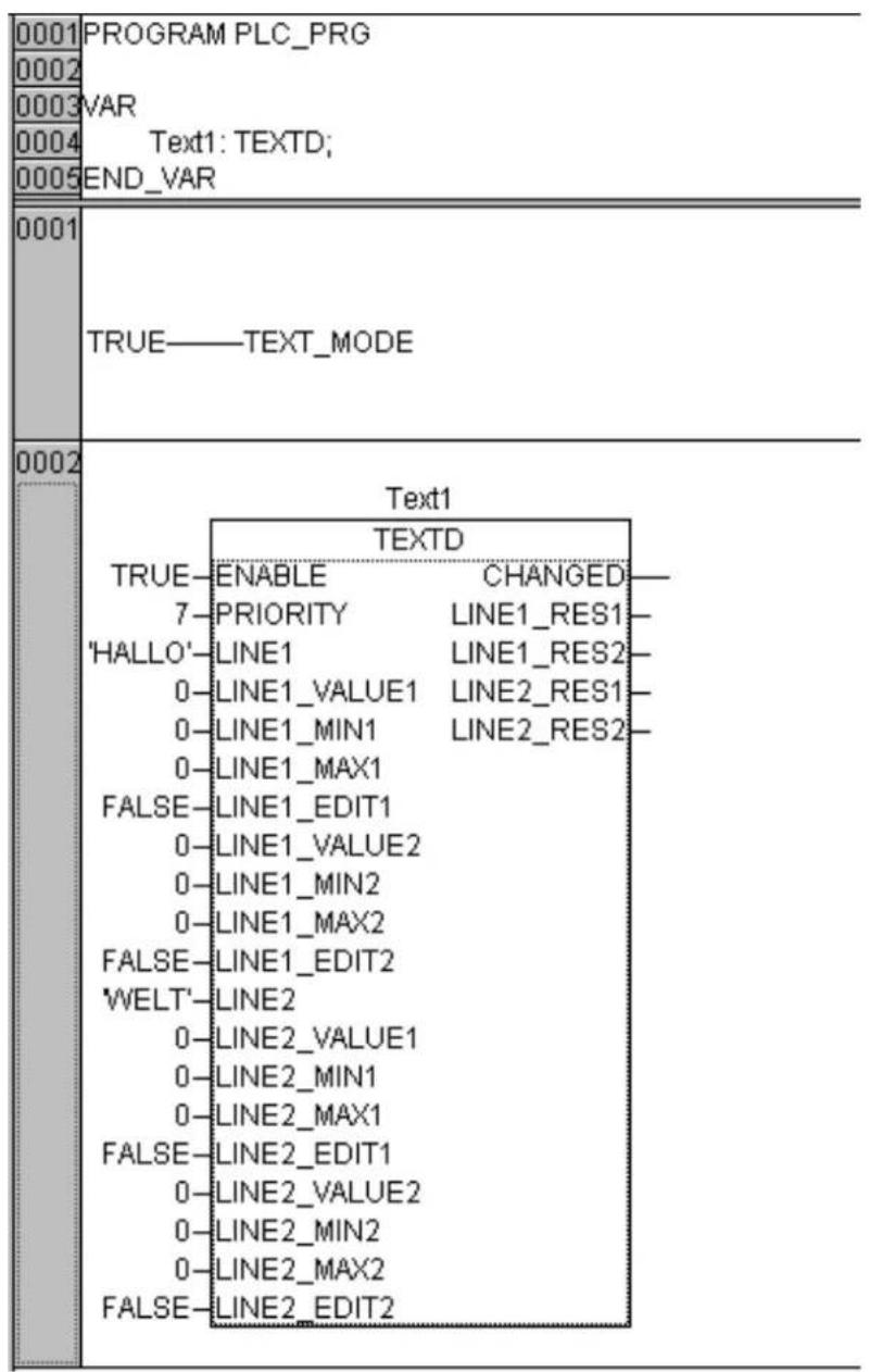
The program extract shows an instance Text1 of the function block "TEXTD" with assigned text data in the programming language Function Block Diagram (FBD). The program displays the text "HALLO WELT".
3.2 Programming with address transfer
Description
In the device-specific library of the controller you find the data structure "text_struct". For each display text screen define a variable type "text_struct". Assign the text data to the variables type "text_struct" by initialising the components of the structure with the corresponding data.
- .enable : BOOL; text enable
• .priority : BYTE; display priority 1 ... 7, 7 = highest - .line1 : STRING(20); display text line 1, if necessary with wildcard "%" and formatting character for process data to be integrated
• .line1_value1 : INT, from left to right the first integrated value in line 1
• .line1_min1 : INT; the lower edit limit, value 1
• .line1_max1 : INT; the upper edit limit, value 1
• .line1_edit1: BOOL; edit enable for value 1
• .line1_value2 : INT; the second value
• .line1_min2 : INT; the lower edit limit, value 2
• .line1_max2 : INT; the upper edit limit, value 2
• .line1_edit2: BOOL; edit enable for value 2 - .line2 : STRING(20); display text line 2, if necessary with wildcard "%" and formatting character for process data to be integrated
• .line2_value1 : INT; from left to right the first integrated value in line 2
• .line2_min1 : INT; the lower edit limit, value 1
• .line2_max1 : INT; the upper edit limit, value 1
• .line2_edit1: BOOL; edit enable for value 1
• .line2_value2 : INT; the second value
• .line2_min2 : INT; the lower edit limit, value 2
• .line2_max2 : INT; the upper edit limit, value 2
• .line2_edit2: BOOL; edit enable for value 2
The default of the components of the structure is 0 or FALSE.
In each line of the text display screen a maximum of two values (process data / variable) can be integrated.
Allowed display formats for the integrated values:
$$ \% \text {nd} = \text {SIGNED INT} = - 3 2 7 6 7 \dots 0 \dots 3 2 7 6 7 $$
$$ \% \mathrm{nu} = \text { UNSIGNED INT } = 0 \dots 65535 $$
$$ \% \mathrm{nx} = \mathrm{HEX} = 0 \dots \mathrm{ffff} $$
$$ \% n X = H E X = 0 \dots F F F F $$
n = 0 ... 5; option:
Number of the represented places of the process data, without n all places are represented (without leading zeros).
In the device-specific library of the controller you find the function block "TEXTA". Create an instance of this function block. The instance sends the text data of a display text to the DDM 100. So the instance must be called cyclically with the addresses of all defined variables type "text_struct". To do so, the address of the text variable is determined with the function "ADR()". The address type "DINT" is converted with the function "DINT_TO_INT" into a variable type "INT" and transferred to an instance of TEXTA.
Programming example in ST
Note: Below you find a commented program extract with address transfer in the programming language Structured Text (ST).
The program displays the text "HALLO WELT".
3.3 Program function keys and LEDs
The 3 function keys (F1, F2, F3) and the 3 LEDs (F1, F2, F3) can be freely assigned. The assignment of the edit keys is fixed.
In the controller configuration you find the following variables which include the key and LED status:
| Function keys | |
| Variable Type | |
| TEXT_KEYS WORD | |
| TEXT_KEY_F1 BOOL (TEXT_KEYS, Bit 0) | |
| TEXT_KEY_F2 BOOL (TEXT_KEYS, Bit 1) | |
| TEXT_KEY_F3 BOOL (TEXT_KEYS, Bit 2) | |
| Edit keys | |
| Variable Type | |
| TEXT_KEYS WORD | |
| TEXT_KEY_ESC BOOL (TEXT_KEYS, Bit 3) | |
| TEXT_KEY_LEFT BOOL (TEXT_KEYS, Bit 4) | |
| TEXT_KEY_RIGHT BOOL (TEXT_KEYS, Bit 5) | |
| TEXT_KEY_DOWN BOOL (TEXT_KEYS, Bit 6) | |
| TEXT_KEY_UP BOOL (TEXT_KEYS, Bit 7) | |
| TEXT_KEY_ENTER BOOL (TEXT_KEYS, Bit 8) | |
| LEDs | |
| Variable Type | |
| TEXT_LEDS WORD | |
| TEXT_LED_F1 BOOL (TEXT_LEDS, Bit 0) | |
| TEXT_LED_F2 BOOL (TEXT_LEDS, Bit 1) | |
| TEXT_LED_F3 BOOL (TEXT_LEDS, Bit 2) | |
3.4 Enable the communication between the controller and the DDM
In the device-specific library of the controller the global variable TEXT_MODE : BOOL is defined for the communication between the controller and the DDM.
Enable the communication between the controller and the DDM:
- Set the system variable TEXT_MODE to TRUE in the controller program.

4. Operation
4.1 Normal operation
After switch-on of the controller the DDM displays
ecomat 100
CS 0014
The DDM is ready for operation.
Then the text with the highest display priority is indicated. If no text is active,
no messages
is indicated.
If there is no communication with the controller, for example because the controller is not switched on,
ERROR communication
is displayed
As soon as the DDM100 and the controller communicate, the error message disappears and the text with the highest display priority is indicated.
Call another active text:
→Scroll with ☐r ↑
The texts are displayed in the order of priority.
If no key is pressed, the selected text is displayed for the set display time (see the section "Set the display time" on page 32). Then the current text with the highest priority is displayed again.
Before the display time has elapsed, pressing of the ⬤ will display the highest priority screen.
Edit process data in a text:
→Get the cursor displayed with or


→Move the cursor to the requested position of the value to be changed with
→Decrement or increment the place above the cursor with

When 9 is exceeded or in the case of 0 a carry is made to the next decade.
→If or ↓ ↑
is pressed for more than 1s, decrementing or incrementing is performed automatically
→Cancel editing with

→End edit with
The cursor disappears from the display. Changed values, if any, are not saved.
4.2 Parameter setting mode
In the parameter setting mode the following unit settings can be made:
- language of the stored texts in English/German.
- display time of a text with low priority until the text with the highest priority is displayed again when no button is pressed. It is also the time until the edit mode is left when no button is pressed.
- flashing time (for a flashing indication of a text line).
- CAN identifier of the messages the controller transfers to the DDM 100. The communication from the controller to the DDM 100 comprises 2 CAN messages. The identifier of the first message is set.
The identifier of the second message is calculated as follows: ID1 message + 1. The identifiers for the communication from DDM 100 to the controller are transferred to the DDM100 by the controller.
Caution: The identifier of the CAN messages must be changed in the controller and in the DDM 100. Depending on the operating system of the controller this is not always possible. In this case the identifier to be set is 7F0 hex.
- bit rate of the CAN interface. You can select from a list of 8 stored bit rates. The bit rate of the DDM 100 must be the same as the bit rate of the controller.
Activate parameter setting mode
After application of the supply voltage the following text is displayed:
ecomat 100
CS0014
Press the ➕ buttons simultaneously once while this text is displayed.
Language selection
When the or button is pressed, the following text is displayed:
PARAMETER
Language English / Sprache Deutsch
Set the desired language by pressing the or button.
Confirm setting by pressing the button.
Cancel setting by pressing the button.
Set display time
When the or button is pressed, the following text is displayed:
PARAMETER
display time xx s/ Meldezeit xx s
By pressing the ☐ button start changing the value and position the cursor to the desired position.
By pressing the or button set the desired value.
Confirm setting by pressing the button. Cancel setting by pressing the button.
Set flashing time
When the or button is pressed, the following text is displayed:
PARAMETER
blink xxxx ms/ Blinker xxxx ms
By pressing the ☐ button start changing the value and position the cursor to the desired position.
By pressing the or button set the desired value.
Confirm setting by pressing the button. Cancel setting by pressing the button.
Set CAN identifier
When the or button is pressed, the following text is displayed:
PARAMETER
By pressing the ☐ button start changing the value and position the cursor to the desired position.
By pressing the or button set the desired value.
Confirm setting by pressing the button. Cancel setting by pressing the button.
Set bit rate
When the or button is pressed, the following text is displayed:
PARAMETER
By pressing the or button scroll the list of stored bit rates.
When the CAN identifier or the bit rate has been changed, press the x button for indication of the following text:
PARAMETER
load / übernehmen
The changed CAN parameters are activated by pressing the button.
As after application of the supply voltage the unit then displays the following text:
ecomat 100
CS0014
4.3 Presentation of keys

 | Function key F1 and LED, function according to the program |
 | Function key F2 and LED, function according to the program |
 | Function key F3 and LED, function according to the program |
 | Escape key, cancels editing or display text screen with the highest priority |
 | Edit key, moves the cursor to the left |
 | Edit key, moves the cursor to the right |
 | Edit key, decreases the value at the cursor position or display text screen with lower priority |
 | Edit key, increases the value at the cursor position or display text screen with higher priority |
 | Enter key, confirms the edited value |
5. Trouble-shooting
| Problem Possible solutions | |
| The DDM does not react Check | wiring and the supply |
| A function key does not react | Check the program code that has been written in the controller for this type of operation. Return the front panel to the manufacturer for inspection. |
| An Edit key does not react | Return the front panel to the manufacturer for inspection |
| The message "no messages" is indicated | Enable the text display screens in the controller program |
| The message "ERROR communication" is indicated | Check in the controller program whether the communication between the controller and DDM has been enabled. If necessary, set the variable TEXT_MODE to TRUE. Check wiring and the controller. |
6. Cleaning

The membrane keys can be scratched by improper cleaning thus becoming unusable.
Clean the membrane keys of the DDM with a cleaning agent which does not attack polyester. Use a soft cloth.
7. Technical data
Application
Display
| Operating voltage | [V] |
| Current consumption | [mA] |
Protection rating
| Operating temperature | [°C] |
Housing dimensions [mm]
Operating keys
LEDs
Interface
Function keys with LEDs
Baud rate:
Identifiers:
Connections
Wiring
Display and input module for controllers
| backlit LCD display2 lines with 16 characters each, freely programmable |
| 10 ... 30 DC (SELV) |
| 100(In case of a fault the current consumption must be limited to max. 1 A by an appropriate fuse) |
| IP64 / III |
| 0 ... +50 |
| 190 x 90 (length x width)height for wall mounting = 32mmheight for control cabinet mounting = 7mminstallation depth for control cabinet mounting = 25mmmaximum thickness of the front panel = 2.5mm |
| a total of 9, of which,3 function keys, can be freely assigned,6 keys with defined function |
| freely programmable via the application program |
| 3 x yellow, freely programmable |
| CAN: specification 2.0 A/B |
| 125 kBaud, High speed to ISO/DIS 11898 |
| 7F0 HEX ... 7F1 HEX (DDM receives text list/text data)7F8 HEX ... 7FA HEX (DDM sends text call, edited process data, key status) |
| 5 WAGO cage-clamp terminals |
| 1: CAN_H2: CAN_L3: GND4: GND5: +24 V |
8. Declaration of conformity
The CE mark is granted on the basis of the EMC guideline EMC 89/336/EEC which has been considered in the standards EN 50081-1 and EN 61000-6-2 and also on the basis of the low voltage guideline considered in the standards EN 61010 and EN 61010 / A1:1995.




- Montage
- Functions of the DDM 100
- Mounting
- Programming
- Mounting
- Control cabinet mounting
- Wall mounting
- Programming
- Programming with data transfer
- Description
- Programming example in FBD
- Programming with address transfer
- Programming example in ST
- Program function keys and LEDs
- Enable the communication between the controller and the DDM
- Operation
- Normal operation
- Parameter setting mode
- Activate parameter setting mode
- Language selection
- Set display time
- Set flashing time
- Set CAN identifier
- Set bit rate
- Presentation of keys
- Trouble-shooting
- Cleaning
- Technical data
- Declaration of conformity
Brand : IFM
Model : CS0014
Category : Industrial electronic module