
Z1J-TD12-13E2 - Drill Cocraft - Free user manual and instructions
Find the device manual for free Z1J-TD12-13E2 Cocraft in PDF.


| Product Type | Impact Drill |
| Model | Z1J-TD12-13E2 |
| Brand | Cocraft |
| Power Supply | 230 V ~ 50 Hz |
| Power Consumption | 500 W |
| No-Load Speed | 0-3000 rpm |
| Max Drilling Diameter (Wood) | 25 mm |
| Max Drilling Diameter (Steel) | 13 mm |
| Max Drilling Diameter (Concrete) | 13 mm |
| Chuck Type | Keyless, 1.5-13 mm |
| Impact Rate | 0-48000 bpm |
| Variable Speed | Yes |
| Reversible | Yes |
| Weight | 1.4 kg |
| Dimensions (L x W x H) | 260 x 65 x 180 mm |
| Cable Length | 2.5 m |
| Protection Class | II (Double insulated) |
| Accessories Included | Depth stop, auxiliary handle, carrying case |
| Maintenance | Keep ventilation slots clean, regularly check carbon brushes |
| Safety Features | Lock-on button, safety switch side handle |
| Repairability | Replaceable carbon brushes, spare parts available |
Frequently Asked Questions - Z1J-TD12-13E2 Cocraft
User questions about Z1J-TD12-13E2 Cocraft
0 question about this device. Answer the ones you know or ask your own.
Ask a new question about this device
Download the instructions for your Drill in PDF format for free! Find your manual Z1J-TD12-13E2 - Cocraft and take your electronic device back in hand. On this page are published all the documents necessary for the use of your device. Z1J-TD12-13E2 by Cocraft.
USER MANUAL Z1J-TD12-13E2 Cocraft
Read the entire instruction manual carefully and make sure that you fully understand it before you use the equipment. Keep the manual for future reference.
Viktig information:
natural_image
Blue and black Cocralf 850-T drill put tool against a textured gray background (no text or symbols visible on the tool body)Art.no Model
18-3175
40-7964
Z1J-TD12-13E2-UK
Z1J-TD12-13E2
Ver. 20160303
Original instructions
Bruksanvisning i original
Originalbruksanvisning
Please read the entire instruction manual before using and save for future use.
We apologise for any text or photo errors and any changes of technical data. If you have any questions concerning technical problems please contact our Customer Service Department (see address on reverse.)
Safety
General safety instructions
Warning! Read all the instructions. Failure to adhere to the following instructions may lead to electric shocks, fires and/or serious injury. The term “power tools” in the warning text below refers to your handheld mains operated or battery operated tool.
SAVE THESE INSTRUCTIONS.
1) The work space
a) Keep the work space clean and well illuminated. Cluttered and areas invite accidents.
b) Do not use electrical hand tools in explosive environments, i.e. nearby flammable liquids, gas or dust. Electrical hand tools generate sparks that could easily ignite dust or fumes.
c) Keep away from children and other spectators while using the electrical hand tool. Interference can make you loose your concentration and control.
2) Electrical safety
a) The electrical hand tools plug must fit correctly in the wall socket. Never modify the plug in any way. Never use an adaptor together with earthed electrical hand tools. Unmodified plugs and suitable wall sockets decreases the risk of electric shock.
b) Avoid body contact with earthed objects, such as pipes, radiators, ovens or refridgerators. There is an increased risk of electrical shock if your body is earthed.
c) Do not expose the electrical hand tool to rain or other wet conditions. If water gets inside an electrical hand tool it increases the risk of electrical shock.
d) Do not misuse the lead. Never use the lead to carry, drag or pull the plug out of the wall socket. Keep the lead away from heat, oil, sharp edges and movable parts. Damaged or tangled leads increases the risk of electrical shock.
e) When you use an electrical hand tool outdoors; use an extension cord suitable for this purpose. Use of an extension cord for outdoor use decreases the risk of electrical shock.
f) If for some reason you must use a power tool in a wet environment, always connect it to the mains via an earth-fault circuit breaker such as an RCD (residual current device). Using an RCD significantly reduces the chances of you receiving an electric shock.
3) Personal safety
a) Pay attention to what you do and use common sense when using electrical hand tools. Never use an electrical hand tool if you are tired or under the influence of drugs, alcohol or medication. One moment of not paying attention while using an electrical hand tool may result in serious injury.
b) Use protective equipment. Always use safety glasses. Using protective equipment such as a face mask, slip resistant protection shoes, a helmet and ear defenders when needed decreases the risk of injury.
c) Avoid accidental starting. Make sure that the switch is set to OFF before you connect the device to the wall socket. Never carry an electrical hand tool with one finger on the trigger or never connect the hand tool to a wall socket when the switch is set to ON, since it may result in injury.
d) Remove all service tools/keys before switching on the hand tool. A service tool forgotten on a rotating part of the electrical hand tool may result in injury.
e) Do not overreach. Make sure you stand steady and well balanced at all times. This gives better control in unexpected situations.
f) Wear suitable clothing. Do not wear loose fitting clothes or jewellery.
Keep hair, clothes and gloves away from movable parts. Loose fitting clothes,
jewellery or long hair could get caught in movable parts.
g) If the equipment for suctioning or collecting dust is available make sure it is connected and used properly. Using technical aid may decrease dust related hazards.
4) Use and maintenance of the electrical hand tools
a) Do not overdrive the hand tool. Use a hand tool suitable for the work you are to perform. The correct electrical hand tool will perform the task better and safer if used at the correct feed rate.
b) Never use the electrical hand tool if the switch does not work properly to turn on and shut off the tool. All electrical hand tools that can not be operated by the switch are dangerous and must be repaired.
c) Unplug the lead from the wall socket before making any adjustments, changes of accessories or storing the electrical hand tool away.
These precautions reduces the risk of unexpected start of the electrical hand tool.
d) Store electrical hand tools that are not being used out of reach from children. Electrical hand tools can be dangerous if they get in the hands of inexperienced users.
e) Maintenance of electrical hand tools. Check if something is incorrectly set, if movable parts are getting jammed, or parts are broken or something else that might cause dysfunction to the electrical hand tool. If something is damaged it must be repaired before use. Many accidents are caused by poorly maintained electrical hand tools.
f) Keep the tools sharp and clean. Properly maintained cutting tools with sharp blades are less disposed to getting jammed and easier to control.
g) Use the electrical hand tool, accessories and such according to the instructions and in a way suitable for the type of electrical hand tool used.
Using the electrical hand tool for work other than suitable work could result in a dangerous situation.
5) Service
a) Repairs and service should only be performed by qualified persons, and only with original spare parts. This guarantees the safety on the electrical hand tool.
Specific Safety Regulations for Impact Drills
- Ear protectors should be worn when using the impact drill.
Exposure to high levels of noise can cause hearing impairment. - Use the supplied side handle when using the impact drill.
Losing control of the drill could result in personal injury.
Safety symbols

Read the entire instruction.

Always use protective glasses or a visor.
Always use ear protection.
Product Description
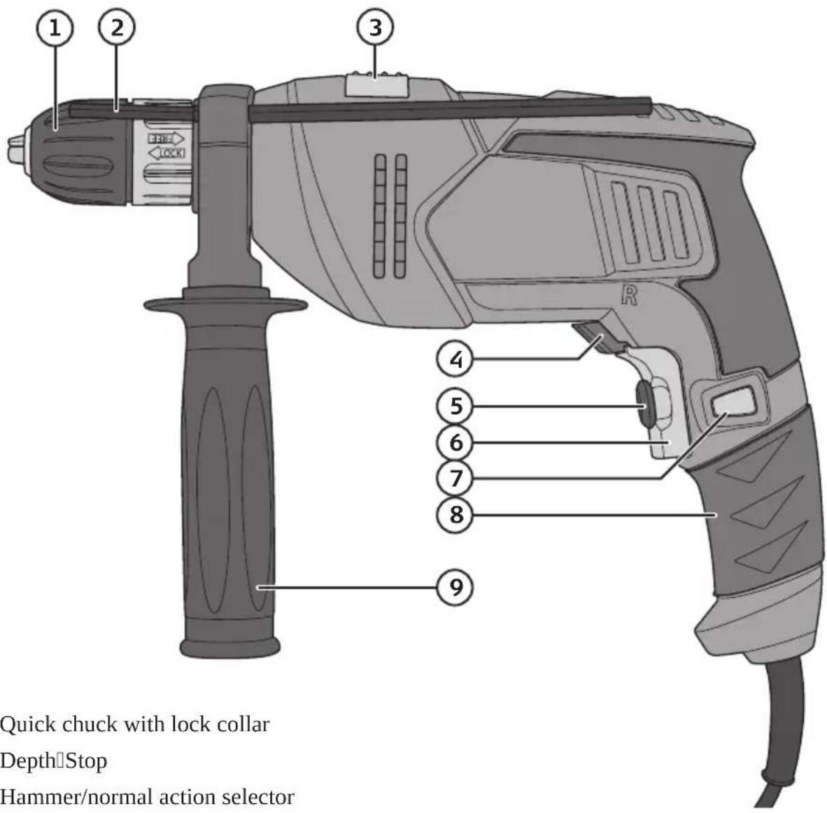
- Quick chuck with lock collar
- DepthStop
- Hammer/normal action selector
- Forward/Reverse Selector
- Stepless Variable Speed Control
- Power Switch
- Safety lock button
- Handle
- Side handle
Use
Chuck
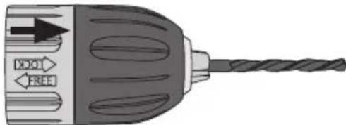
Note: The hammer drill has a new type of keyless quick chuck (1.5–13 mm). The keyless chuck's rear lock collar is slid forwards for locking tools into placed and slid backwards for releasing tools during tool changes.
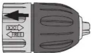
- Pull the rear collar backwards to release the chuck.
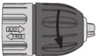
- Twist the front collar clockwise (as seen from the back) until the jaws are wide enough apart to allow the tool to enter.
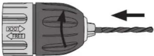
-
Insert a drill bit or other tool.
-
Screw the front collar anti-clockwise (as seen from the back) until the jaws grasp the tool tightly and securely.
natural_image
Illustration of a drill bit with directional arrows indicating power and free direction (no text or symbols)- Slide the rear collar forwards to lock the chuck. Warning: Do not try to tighten the chuck by holding the rear collar whilst starting the drill; this could result in personal injury.
Side handle
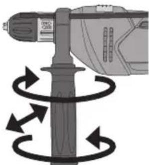
- Screw the side handle anticlockwise to undo it.
- Set the side handle in the desired position, set the depth stop if necessary.
- Screw the side handle clockwise to lock both the handle and depth stop.
Power Switch
- Plug the lead into a wall socket after inserting a tool into the chuck and tightening it.
- Start the impact drill by gently pulling the power switch (6), check that the tool rotates in the correct direction. Release the power switch to stop the drill.
- When the chuck is rotating, the power switch can be locked by pressing the lock button (7) and releasing the power switch. To stop the drill, pull the power switch and then release it.
natural_image
Diagram of a drill bit with motion arrows indicating rotational motion (no text or symbols)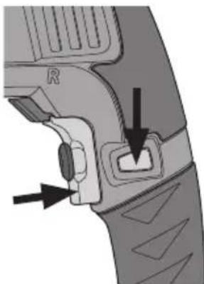
natural_image
Close-up of a mechanical component with arrows indicating a step or adjustment (no text or symbols visible)Changing Direction of Rotation
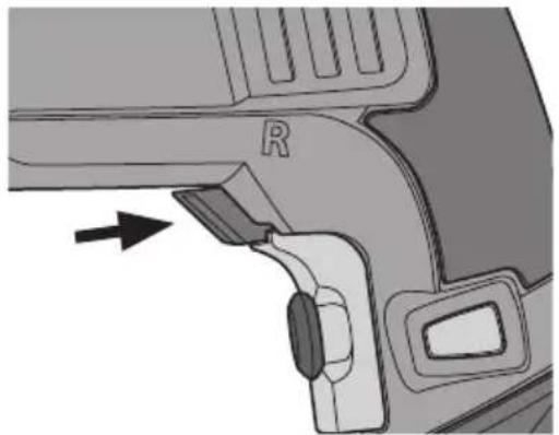
- Stop the drill.
- Turn the selector (4) to the right or left to select the direction of rotation.
Note: The drill will not work if the selector is between settings. The selector switch must be fully turned in the desired direction.
Stepless Variable Speed Control
- Start the drill by pulling the power switch (6).
- Turn the speed selector (5) anticlockwise to reduce speed or clockwise to increase speed.
- The speed selector limits how far the power switch can be pulled in.
Note: Always start drilling at a low speed if drilling without a pilot hole or centre-punch mark. As a rule, use higher speeds with thin drill bits and lower speeds with thicker bits. Cleaning and polishing usually require a high speed.
Impact Drilling or Normal Drilling
- Stop the drill completely.
- Set the selector switch (3) to the desired drill action. Select impact drilling for hard materials (concrete, stone, etc) and normal drilling for steel, aluminium and wood, etc.
- When the hammer symbol can be seen, the drill is set on impact drill mode.
- When the drill bit symbol can be seen, the drill is set on normal drill mode.
Warning: Do not move the selector unless the chuck is completely stationary. Make sure that the selector is set correctly, a click can be heard when it locks into place.
natural_image
Mechanical component diagram showing a bracket with a labeled 'R' and an arrow indicating direction (no text or symbols beyond basic labels)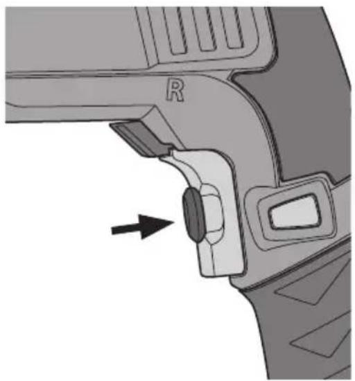
natural_image
Mechanical component diagram showing a lever mechanism with an arrow indicating direction (no text or symbols present)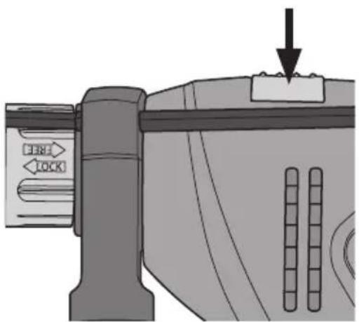
Useful Tips
- After having worked the drill hard for a while let the motor run without load for a few minutes (until the air leaving the ventilation slits is at room temperature) to allow it to cool it down.
- Use the side handle to help maintain full control when drilling.
- Only use sharp tools.
- Use Titanium coated drill bits for hard metals and Tungsten Carbide tipped drill bits for concrete/tiles. If in doubt read the packet.
- Fasten the workpiece down securely. Use clamps or vices when you can, this will leave you with both hands free to manoeuvre the machine with, which increases precision.
- If you are drilling into thin materials it is important that you place a small piece of waste material behind the hole to be drilled, otherwise there is a risk of burring on the back.
- Hold the drill perpendicular to the workpiece before you start drilling (look from several directions) make sure that you do not tilt the drill when drilling.
- Do not press too hard (so that the machine loses speed), let the tool do the job! Reduce pressure before the drill breaks through the material.
- Let the drill bit spin and lift it up after drilling through, it allows the machine to cool down and the drill bit is freed of dust and wood chips.
Things to consider when drilling into wood and plastic
- For wood and other soft materials there are several types of tools, choose the tool most suitable for the work to be done. Test drill on a piece of waste first.
- The tool can overheat if you don't pull it up often to free it of sawdust.
- Place a small piece of waste material behind the hole to be drilled before starting to drill otherwise there is a risk of burring around the edges of the hole on the back.
Things to consider when drilling into metal
• Mark the hole using a centre punch.
- The tool can overheat if you use the wrong speed. Use cooling liquid suitable for your material e.g. methylated spirit for aluminium (cast iron and brass are cut dry).
- Use a low gear and low speed for big holes.
- Be extra careful with the clamping of thin or sharp metal objects so that they do not come loose and cause damage or injury, use a vice if possible.
Things to consider when drilling into concrete, tile or brick
- Use Tungsten carbide tipped drill bits.
- Use a drill with hammer/impact action and work carefully, applying constant pressure.
- The material residue comes out of the drilled hole as powder or dust, wear a dust mask.
- Use the hammer function when working on concrete or brick by carefully applying constant pressure. DO NOT use the hammer drill for tile.
Care and Maintenance
- Before using the drill, make sure that all screws are tightened. When hammer drilling the machine will vibrate considerably.
- Make sure the cool air vents on the machine are free and open.
- Clean with a damp cloth and mild washing up liquid when needed. Never use solvents or strong cleaning agents.
- Store the instruction manual together with the drill.
Responsible disposal
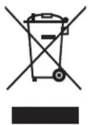
This symbol indicates that this product should not be disposed of with general household waste. This applies throughout the entire EU. In order to prevent any harm to the environment or health hazards caused by incorrect waste disposal, the product must be handed in for recycling so that the material can be disposed of in a responsible manner. When recycling your product, take it to your local collection facility or contact the place of purchase. They will ensure that the product is disposed of in an environmentally sound manner.
natural_image
Symbol of a trash bin crossed with no text or labels, accompanied by a black rectangular block below (no readable text or symbols)Specifications
Mains Supply 230–240 V AC, 50 Hz
Power 850 W
No-Load Speed 0–2800 rpm
Chuck Capacity 1.5–13 mm
Drilling Capacity Steel: 13 mm
Concrete: 13 mm
Wood: 25 mm
Weight 2.35 kg
Sound power LwA: 97 dB(A), K: 3 dB
LpA: 86 dB(A), K: 3 dB
Vibration Drilling in concrete: a
Drilling in metal: a
h, ID: 7.19 m/s², K: 1.5 m/s² h, ID: 2.32 m/s², K: 1.5 m/s²
Slagborrmaskin
Art.nr 18-3175
40-7964
Modell Z1J-TD12-13E2-UK
Z1J-TD12-13E2
natural_image
Illustration of a drill bit with directional arrows indicating tool movement (no text or symbols)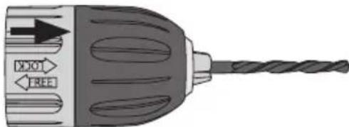
natural_image
Illustration of a drill bit with directional arrows indicating tool movement (no text or symbols)natural_image
Diagram of a drill bit with motion arrows indicating rotational motion (no text or symbols)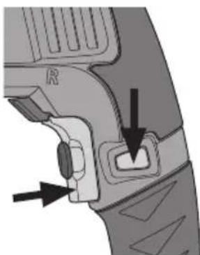
natural_image
Close-up of a mechanical component with arrows indicating a step or adjustment (no text or symbols visible)natural_image
Mechanical component diagram showing a curved bracket with labeled part 'R' and an arrow pointing to a specific feature (no text or symbols beyond the label)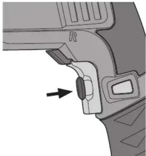
natural_image
Mechanical component diagram showing a lever mechanism with an arrow indicating direction (no text or symbols present)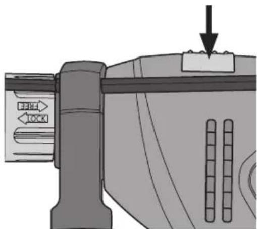
natural_image
Mechanical component diagram showing a lever mechanism with directional arrows and a downward arrow (no text or symbols)Användningstips
natural_image
Symbol of a trash bin crossed with no visible text or labelsSpecifikationer
Nätspänning 230–240 V AC, 50 Hz
Effekt 850 W
Varvtal, obelastad 0–2800 v/min
Chuckkapacitet 1,5–13 mm
Borrkapacitet Stål: 13 mm
Betong: 13 mm
Trä: 25 mm
Vikt 2,35 kg
Ljudnivåer LwA: 97 dB(A), K: 3 dB
LpA: 86 dB(A), K: 3 dB
Vibration Borrning i betong: a
Borrning i metall: a
h, ID: 7,19 m/s², K: 1,5 m/s² h, ID: 2,32 m/s², K: 1,5 m/s²
Slagbormaskin
Art.nr. 18-3175
40-7964
Modell Z1J-TD12-13E2-UK
Z1J-TD12-13E2
natural_image
Illustration of a drill bit with motion arrows indicating rotational motion (no text or symbols)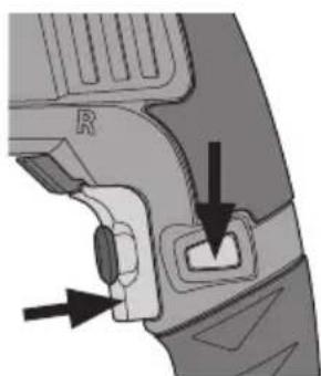
natural_image
Close-up of a mechanical component with arrows indicating a step or adjustment (no text or symbols visible)natural_image
Mechanical component diagram showing a bracket with labeled part 'R' and an arrow indicating direction (no text or symbols beyond basic labels)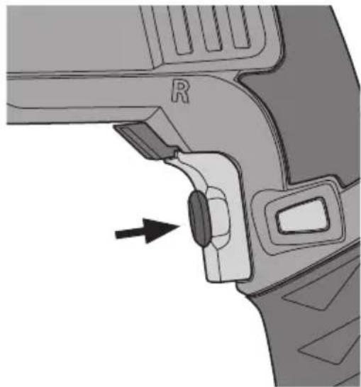
natural_image
Mechanical component diagram showing a lever mechanism with an arrow indicating direction (no text or symbols present)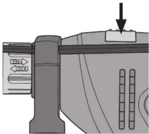
natural_image
Mechanical component diagram showing a lever mechanism with directional arrows and a load applied (no text or symbols)Brukertips
natural_image
Symbol of a trash bin crossed with no text or numbers, representing waste sorting or disposal (no text present)Spesifikasjoner
Spenning 230–240 V AC, 50 Hz
Effekt 850 W
Turtall (ubelastet) 0–2800 o/min
Chuck-kapasitet 1,5–13 mm
Borekapasitet Stål: 13 mm
Betong: 13 mm
Tre: 25 mm
Vekt 2,35 kg
Lydnivåer LwA: 97 dB(A), K: 3 dB
LpA: 86 dB(A), K: 3 dB
natural_image
Illustration of a drill bit with labeled arrows (no text or symbols beyond directional indicators)natural_image
Diagram of a drill bit with motion arrows indicating rotational motion (no text or symbols)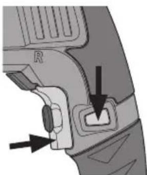
natural_image
Close-up of a mechanical component with arrows indicating direction (no text or symbols)natural_image
Mechanical component diagram showing a bracket with labeled part 'R' and an arrow indicating direction (no text or symbols beyond the label)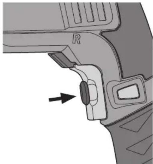
natural_image
Mechanical component diagram showing a lever mechanism with an arrow indicating direction (no text or symbols present)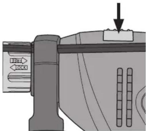
natural_image
Mechanical component diagram showing a lever mechanism with directional arrows and a downward arrow (no text or symbols)Käyttövinkkejä
natural_image
Symbol of a trash bin with crossed lines indicating no waste or restriction, and a solid rectangle below (no text or labels)Tekniset tiedot
natural_image
Illustration of a drill bit with no text or symbols on the drill facenatural_image
Diagram of a drill bit with motion arrows indicating rotational motion (no text or symbols)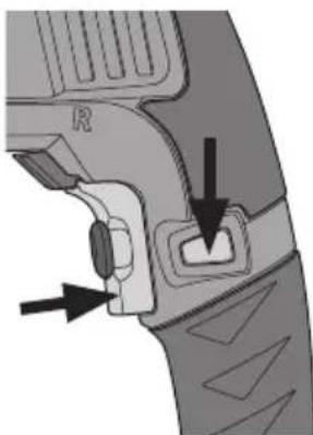
natural_image
Close-up of a mechanical component with arrows indicating a step or adjustment (no text or symbols visible)natural_image
Mechanical component diagram showing a lever and adjustment knob with an arrow indicating direction (no text or symbols present)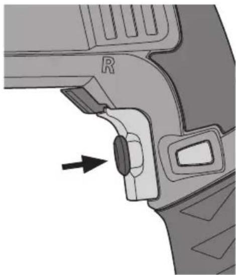
natural_image
Mechanical component diagram showing a bracket with a labeled 'R' and an arrow pointing to a button (no text or symbols beyond the label)natural_image
Symbol of a trash bin crossed out by two crossed lines, with no text or labels present.Technische Daten
Declaration of Conformity
Declares that this product complies with the requirements of the following directives and standards
Machinery Directive 2006/42/EC
EN 60745-1:2009
+A11:2010
EN 60745-2-1:2010
EMC Directive 2004/108/EC
EN 55014-1:2006
EN 55014-2:1997
+A1:2001+A2:2008
EN 61000-3-2:2006
EN 61000-3-3:2008
Henrik Alfredsson
Manager Technique & Quality
Insjön, Sweden, 2016-02-17
Sverige
Postal 10 - 13 Market Place
Kingston Upon Thames
Surrey
KT1 1JZ
Deutschland
Kundenservice
- Viktig information:
- Safety
- General safety instructions
- SAVE THESE INSTRUCTIONS.
- 1) The work space
- 2) Electrical safety
- 3) Personal safety
- 4) Use and maintenance of the electrical hand tools
- 5) Service
- Specific Safety Regulations for Impact Drills
- Safety symbols
- Product Description
- Use
- Chuck
- Side handle
- Power Switch
- Changing Direction of Rotation
- Stepless Variable Speed Control
- Impact Drilling or Normal Drilling
- Useful Tips
- Things to consider when drilling into wood and plastic
- Things to consider when drilling into metal
- Things to consider when drilling into concrete, tile or brick
- Care and Maintenance
- Responsible disposal
- Specifications
- Slagborrmaskin
- Användningstips
- Specifikationer
- Slagbormaskin
- Brukertips
- Spesifikasjoner
- Käyttövinkkejä
- Tekniset tiedot
- Technische Daten
- Declaration of Conformity
- Sverige
- Deutschland
Brand : Cocraft
Model : Z1J-TD12-13E2
Category : Drill