
HD 285 - Drill Cocraft - Free user manual and instructions
Find the device manual for free HD 285 Cocraft in PDF.


| Product Type | Pillar Drill (Bench Drill Press) |
| Brand | Cocraft |
| Model | HD 285 |
| Motor Power | 230 W input, 350 W output, 50 Hz |
| Chuck Capacity | 13 mm (0.51 in) |
| Spindle Speeds | 5 speeds: 580, 850, 1220, 1650, 2650 rpm |
| Max Distance Chuck to Table | 285 mm (11.2 in) |
| Max Distance Chuck to Base | 370 mm (14.6 in) |
| Max Spindle Travel | 50 mm (2.0 in) |
| Distance Column to Spindle Center | 100 mm (3.9 in) |
| Overall Dimensions (L x W x H) | 403 x 180 x 690 mm (15.9 x 7.1 x 27.2 in) |
| Net Weight | 19 kg (41.9 lb) |
| Table Tilt | Yes, adjustable via bolt |
| Depth Stop | Yes, adjustable with lock nuts |
| Chuck Type | Keyed chuck with chuck key |
| Feed Handles | 3 included |
| Safety Features | Belt cover safety switch, emergency stop, safety instructions |
| Construction Material | Metal (cast iron/steel) and plastic components |
| Included Accessories | Chuck key, feed handles, locking lever, base plate, column, table support, instruction manual |
| Warranty | Refer to manual for details |
Frequently Asked Questions - HD 285 Cocraft
User questions about HD 285 Cocraft
0 question about this device. Answer the ones you know or ask your own.
Ask a new question about this device
Download the instructions for your Drill in PDF format for free! Find your manual HD 285 - Cocraft and take your electronic device back in hand. On this page are published all the documents necessary for the use of your device. HD 285 by Cocraft.
USER MANUAL HD 285 Cocraft
natural_image
Cocraft HD 285 drill press machine with blue and black components (no visible text or symbols)Art.no Model
18-3054
ZJ4113H-UK
30-9540
ZJ4113H

Important!
Read the entire instruction manual carefully and make sure that you fully understand it before you use the equipment. Keep the manual for future reference.
Viktig information:
Original instructions
Bruksanvisning i original
Originalbruksanvisning
Please read the entire instruction manual before use and save it for future reference. We reserve the right for any errors in text or images and for making any necessary technical changes to this document. If you should have any questions concerning technical problems please contact our Customer Services.
Safety
General safety instructions
Warning! When using this tool all basic safety precautions must be followed to avoid the risk of fire, electric shock and personal injury. Read these instructions carefully before using the product and keep them for future reference.
- Keep the working area tidy.
Cluttered areas and benches invite accidents.
• Take stock of your working environment.
Do not expose the tool to rain. Do not use the tool in moist or wet areas. Keep the working area well lit. Never operate the tool near flammable liquid or gas.
- Avoid electric shocks.
Avoid body contact with earthed objects, such as pipes, radiators, ovens or refrigerators.
- Keep other people at a safe distance.
Do not allow anyone not involved in the work process to touch the tool or its electric cable, especially children. Keep all bystanders at a distance.
-
Store the tool in a safe place.
When your tools are not in use, keep them in a locked, dry area, away from children. -
Do not overload the tool.
Correct feed rate makes the work better and safer.
- Use the correct tool for the job. Do not try to use small tools to perform jobs requiring more powerful tools. Do not use a tool for a purpose for which it was not designed, e.g. using a circular saw for lopping branches off trees.
- Wear suitable clothing. Do not wear loose-fitting clothing or jewellery, they could get caught in moving parts. Non-slip shoes are recommended for outdoor work. Wear a hairnet or similar if you have long hair.
- Always use safety wear. Wear safety glasses. Use a face mask or dust filter when working in dusty environments.
- Use dust extractors. If the tool is equipped with or connected to a dust extractor/collector, make sure that it is turned on and used correctly.
- Do not misuse the lead. Do not jerk the lead, grip the plug itself when disconnecting the power. Make sure that the mains lead does not come into contact with heat, oil, or sharp edges.
- Clamp the workpiece down tightly.
If possible use vices or clamps to hold the workpiece in place. This is much safer than holding the workpiece in one hand.
- Do not reach too far.
Make sure that you stand steady and balanced all the time.
- Look after you tools.
Make sure that they are clean and that the edges are sharp for maximum effect and best results. Follow the manuals recommendations regarding lubrication and replacement of accessories. Inspect the mains lead regularly. If it is damaged it should be replaced by a qualified service technician. Inspect all leads and cables regularly to check for any damage. Make sure that the machine's/tool's handles and controls are clean, dry and free from oil and grease.
- Turn the power off.
Pull out the plug and push in the emergency stop button before servicing or changing any blades, drill bits, cutters or sanding discs.
- Remove all spanners and repair tools.
Make a habit of checking to make sure that the machine is free of all spanners and tools before turning the power on.
- Avoid unwanted starting.
Do not walk around with your finger on the trigger of a power tool if it is plugged in. Make sure that the on/off switch is set to OFF before plugging in any power tool.
- Use the correct extension leads.
If you use extension leads outdoors, only use those designed for outdoor use. Only use extension leads with thick enough diameter core wires and roll out the whole lead.
- Use your common sense and be careful.
Think before carrying out any task, so that it is carried out safely. Never operate machines/power tools when you are tired or under the influence of medicine.
- Check the following before turning the tool on:
- That all guards and other parts are intact and in working order.
- That moving parts are free and correctly aligned.
- That no moving parts can get caught.
- That no defects are apparent.
- Other factors that can influence the execution of the work.
- A safety guard or any other part that is damaged should be repaired by a tradesman or replaced. Damaged power leads and switches must always be replaced by a tradesman. Never operate a tool if you cannot stop or start the tool comfortably.
- Use only recommended accessories.
The use of non-recommended accessories can cause accidents and personal injury.
- Should only be repaired by a qualified technician.
The tool conforms to current safety requirements. Repairs to the tool should only be carried out by a tradesman using original spares; otherwise the tool could cause accidents and personal injury.
Safety instructions specific to Pillar Drills
- Pillar drills may only be used indoors in dry areas.
- Do not work on a workpiece that is too small to fasten down safely.
- Keep your hands away from the end of the drill.
- Do not use drill bits longer than 175 mm or which protrude more than 150 mm from the chuck. They might bend or break.
- Only use drill bits intended for the material of the workpiece. Do not use circular wire brushes, routers, shapers, hole cutters or rotary planes in this pillar drill.
- When drilling large workpieces, support them at table level.
- Do not drill freehand, use clamps or vices to secure the workpiece.
- Avoid overloading the drill. Do not press down too hard.
- Make sure that there are no nails or foreign objects in the workpiece.
- If the workpiece is hanging over the side of the table and there is a danger of it falling off, clamp it down or support the other end of the workpiece.
- If using a drill vice, clamp it onto the table.
- Make sure that all clamps are properly tightened before you start drilling.
- Do not place any other tools on or move the workpiece on the table whilst the drill is running.
Guide to safety symbols
The symbols below apply when using this pillar drill. Read them and make sure that you understand what they mean before using the drill.

Read the instruction manual.

Use ear defenders.

Use safety glasses or a visor and wear a face mask.
Unpacking and checking all parts
- Remove all the contents from the package and make sure that everything is there before you throw the packaging away.
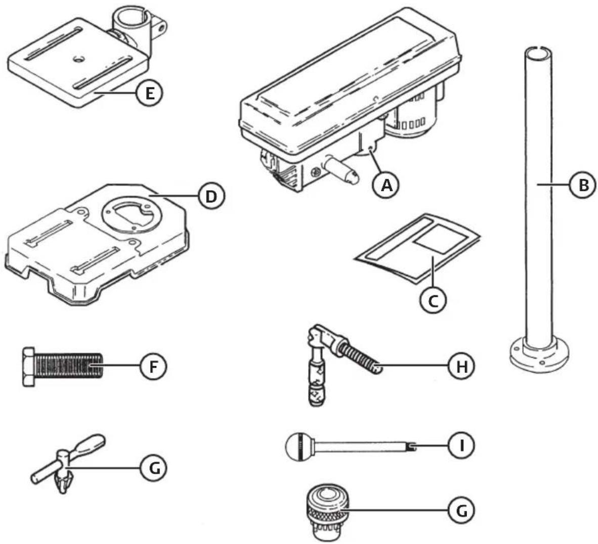
A) 1 × main body
F) 3× socket set screw M8 × 20
B) 1× column
G) 1× chuck and chuck key
C) 1× instruction manual
H) 1× locking lever
D) 1× base plate
1) 3× feed handles
E) 1× table support
-
Wipe the film of oil off the table and column. Use a regular cleaning agent to remove grease and dirt.
-
Wax the table and column to prevent them from rusting. Wipe all parts carefully with a clean, dry rag.
Description
Table removed for better view.
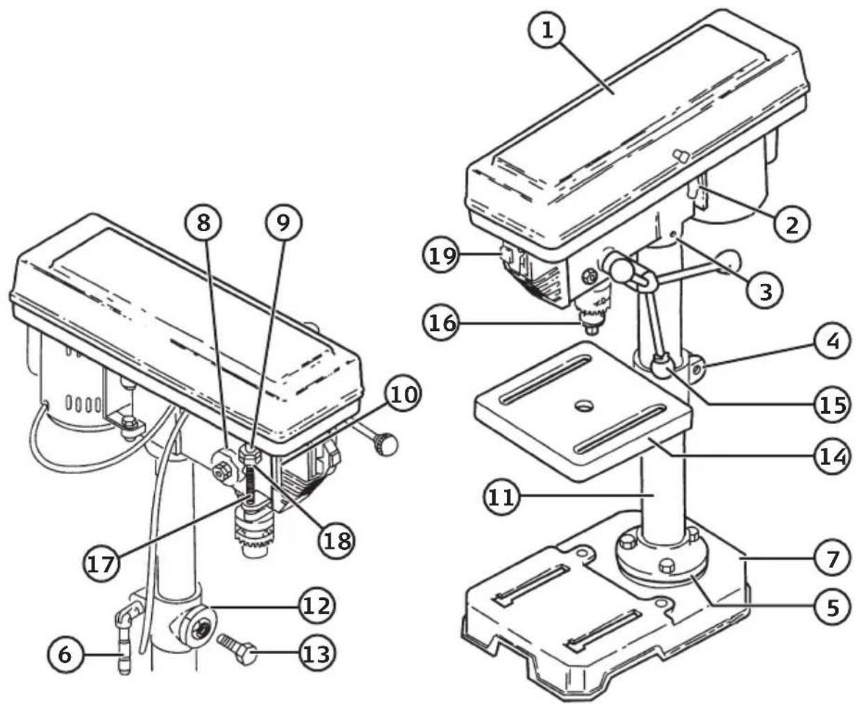
- Belt housing
- Locking lever
- Set screws
- Table clamp
- Column clamp
- Locking lever
- Base plate
- Return spring
- Depth indicator
-
Depth scale
-
Column
- Tilt angle scale
- Bolt for table
- Table
- Feed handle
- Chuck
- Depth stop
- Lock nuts
- On/off switch
Assembly
All the parts are individually wrapped.
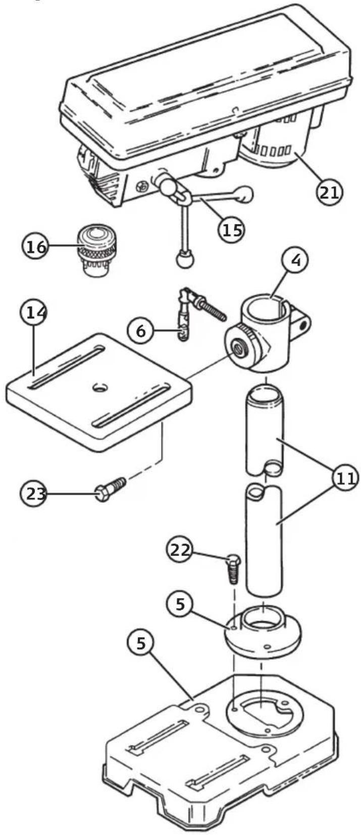
Assemble the pillar drill as shown in the diagram:
- Table clamp (4)
- Locking lever (6)
- Column (11)
- Base plate (7)
- Column clamp (5)
- Bolt M8 × 20 (22)
- Bolt for table (23)
- Table (14)
- Main unit (21)
- Chuck (16)
- Feed handle (15)
Use
Changing the spindle speed
The spindle speed can be altered by moving the belt between the pulleys. The machine is equipped with a safety switch which automatically shuts off the machine if the belt cover is opened.
Move the belt like this
- Open the belt cover by loosening the screws on the right side of the cover.
- Undo the locking lever (2).
- Move the belt to the position giving you the desired speed. Use the table on the inside of the belt cover.
- The belt is automatically tensioned by a spring but may tensioned a little more by pushing the motor away from the main body. Lock the locking lever (2). The belt is correctly tensioned when you can flex it approx. 1 cm.
- Close the belt cover and screw it down so that the machine can be used.
Spindel Speeds
Belt Position Rpm
| A. | 2650 |
| B. | 1880 |
| C. | 1370 |
| D. | 900 |
| E. | 580 |
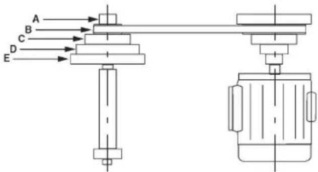
Table depth stop
The table is fitted with a depth stop (17) which can be adjusted using 2 lock nuts (18).
Chuck
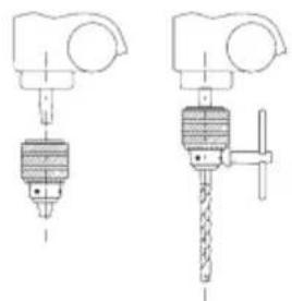
Drills and cylindrical shafted tools up to 13 mm in diameter can be fastened in the chuck with the chuck key.
Securing the workpiece
The table is slotted so that the drill press vices can be bolted to it.
Adjusting the table
The table can be moved up and down the column when the locking lever (6) on the back of the table support (4) is undone.
Adjust the table (14) so that there is enough room between the drill and the table for the workpiece. The table can also be moved to the side if you wish to fix a workpiece directly to the base of the drill (7).
natural_image
Technical line drawing of two mechanical components with no visible text or symbols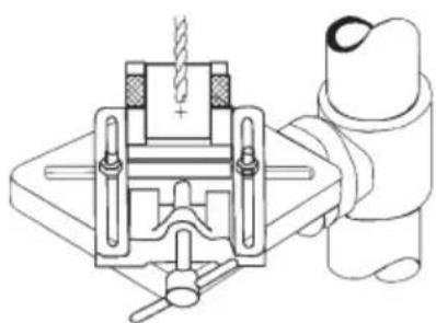
natural_image
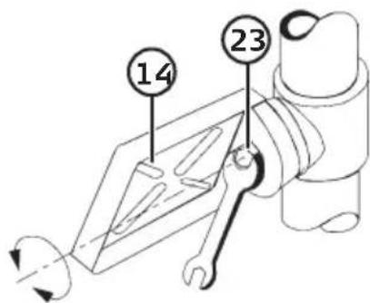
Technical line drawing of a mechanical clamp or vise assembly (no text or symbols)If you wish to drill at an angle, the table can be tilted and the workpiece clamped to the table. In that case undo the bolt (23). Move the table (14) to the desired position and then tighten the bolt (23) again.
Rpm and rate of feed
The drill is fed using the three feed levers (15). The spindle speed is determined by the size of drill bit and the type of material being drilled. The rate of feed is a crucial factor for the life of the drill bit and quality of result.
Follow these basic rules:
- The bigger the diameter drill bit, the lower the speed.
- If the material being drilled is hard there is a natural urge to apply more pressure to the drill, but to avoid overheating the drill bit on such occasions one should apply less pressure and lower the speed of the spindle. Moreover, the drill bit needs to be cooled with a suitable cooling solution depending on the type of material.
When drilling into thin material be careful not to apply too much pressure or feed too quickly. When drilling deep holes (twice the diameter of the drill bit) it can be difficult to get rid of the waste, which can lead to the drill bit becoming hot. It is therefore a good idea to reduce the feed rate and remove the waste by lifting the drill out of the hole from time to time. When drilling holes larger than 8 mm you should first drill a pilot hole so the tip of the drill bit is not overloaded.
Lubrication
All bearings are permanently lubricated and there is no need for extra lubrication. The rack and pinion gears and the spindle should be regularly lubricated.
Care and maintenance
• From time to time all the dust that has accumulated in the motor should be blown out.
- A layer of car polish on the column and table top help keep them clean.
Responsible disposal
This symbol indicates that this product should not be disposed of with general household waste. This applies throughout the entire EU. In order to prevent any harm to the environment or health hazards caused by incorrect waste disposal, the product must be handed in for recycling so that the material can be disposed of in a responsible manner. When recycling your product, take it to your local collection facility or contact the place of purchase. They will ensure that the product is disposed of in an environmentally sound manner.
natural_image
Symbol of a trash bin crossed out by two crossed lines, with no text or labels present.Troubleshooting
| Problem Possible cause | Action | |
| Noise when running. Wrong | g belt tension. Adjust the tension. | |
| Dry spindle. Lubricate the spindle. | ||
| Loose spindle pulley. Make sure that the lock nut is tight. Tighten the screws if needed. | ||
| Loose drive belt pulley. Tighten the pulley screws. | ||
| The drill bit overheats. Wrong | speed. Change speed. | |
| No waste coming from hole. Lift the drill to clean it often. | ||
| Blunt drill bit. Sharpen the drill bit. | ||
| Feed rate too slow. Increase rate of feed. | ||
| No lubricant/coolant. Lubricate/cool the drill bit. | ||
| Drill bit wanders. Knot in w | wood or incorrectly ground drill bit. | Sharpen the drill bit correctly. |
| Bent drill bit. | Replace drill bit. | |
| Splintering on the back of the workpiece. | No waste wood under workpiece. | Place a piece or waste wood under. |
| The workpiece is loose. | It needs clamping. | Support or clamp the workpiece. |
| The drill bit sticks in the workpiece. | The workpiece is “snatching” or too much pressure on the drill bit. | Support or clamp the workpiece. |
| Belt tension too low. | Adjust the tension. | |
| The drill bit “wobbles”. | Bent drill bit. | Use a straight drill bit. |
| Worn spindle bearing. | Replace bearing. | |
| Drill bit not straight. | Insert drill bit correctly. | |
| Chuck mounted incorrectly. | Mount chuck correctly. | |
| The spindle returns too slowly or too quickly. | Wrong spring tension. | Adjust the tension. |
| The chuck won’t stay in place. | Dirt, grease or oil on the chuck taper or on the spindle. | Clean the taper and the spindle with a suitable cleaning agent. |
Specifications
| Motor | 230 W, 50 Hz, 350 W |
| Chuck capacity | 13 mm |
| Distance from column to spindle centre | 100 mm |
| Max. spindle travel | 50 mm |
| Max. distance from chuck to table | 285 mm |
| Max. distance from chuck to base | 370 mm |
| Spindle speeds | 580–850–1220–1650–2650 rpm |
| Overall size (L × W × H) | 403 × 180 × 690 mm |
| Net weight | 19 kg |
Pelarborrmaskin
Art.nr 18-3054 Modell ZJ4113H-UK
30-9540
ZJ4113H
A) 1 st. huvud
F) 3 st. sexkantskruv M8 × 20
B) 1 st. pelare
natural_image
Technical line drawing of two mechanical components with no visible text or symbols
natural_image
Technical line drawing of a mechanical clamp or vise assembly (no text or symbols)natural_image
Symbol of a trash bin crossed with no text or labels, accompanied by a black rectangle below (no readable text or symbols)Felsökning
Bruk
Forandre turtall på spindelen
natural_image
Technical line drawing of two mechanical components with no visible text or symbols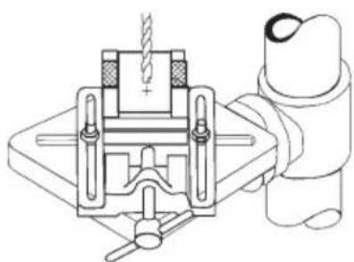
natural_image
Technical line drawing of a mechanical clamp or vise assembly (no text or symbols)natural_image
Symbol of a trash bin with crossed lines indicating no waste or discharge (no text or labels)Feilsøking
Maks. Innvendig diameter (chuck)
Avstand søyle - spindelsentrum
Käyttö
natural_image
Technical line drawing of two mechanical components with no visible text or symbols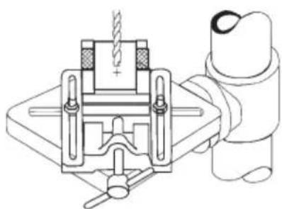
natural_image
Technical line drawing of a mechanical clamp or vise assembly (no text or symbols)natural_image
Symbol of a trash bin crossed with no visible text or labelsVirheenetsintä
Bedienung
natural_image
Technical line drawing of two mechanical components with no visible text or symbols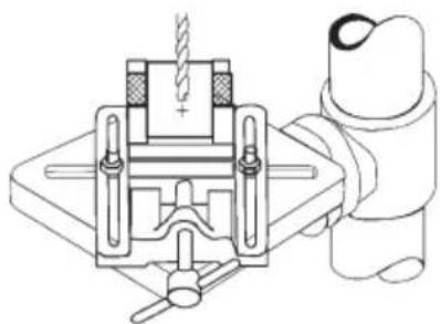
natural_image
Technical line drawing of a mechanical clamp or vise assembly (no text or symbols)natural_image
Symbol of a trash bin with crossed lines indicating no waste or restriction, and a solid black rectangle below (no text or labels)Fehlersuche
Declaration of Conformity
Declares that this product complies with the requirements of the following directives and standards
Machinery Directive 2006/42/EC
EMC Directive 2014/30/EU
EN 61029-1: 2009/A11:2010
EN ISO 12100:2010
EN 55014-1: 2006/A2:2011
EN 55014-2: 1997/A2:2008
EN 61000-3-2: 2014
EN 61000-3-3: 2013
Henrik Alfredsson
Manager Technique & Quality
Insjön, Sweden, 2017-08-15
CLAS OHLSON AB, SE-793 85 INSJÖN, SWEDEN
Sverige
Postal 10 - 13 Market Place
Kingston Upon Thames
Surrey
KT1 1JZ
Deutschland
Kundenservice Hotline: 040 2999 78111
E-Mail: kundenservice@clasohlson.de
Homepage
www.clasohlson.de
- Safety
- General safety instructions
- Safety instructions specific to Pillar Drills
- Guide to safety symbols
- Unpacking and checking all parts
- Description
- Assembly
- Use
- Changing the spindle speed
- Move the belt like this
- Spindel Speeds
- Table depth stop
- Chuck
- Securing the workpiece
- Adjusting the table
- Rpm and rate of feed
- Follow these basic rules:
- Lubrication
- Care and maintenance
- Responsible disposal
- Pelarborrmaskin
- Bruk
- Forandre turtall på spindelen
- Käyttö
- Bedienung
- Declaration of Conformity
- Sverige
- Deutschland
Brand : Cocraft
Model : HD 285
Category : Drill