
TH-F7E - Ham Radio KENWOOD - Free user manual and instructions
Find the device manual for free TH-F7E KENWOOD in PDF.
| Product Type | FM Portable Amateur Radio |
| Brand | KENWOOD |
| Model | TH-F7E |
| Transmission Bands | 144-146 MHz (2 m) and 430-440 MHz (70 cm) |
| Wide Band Receiver | 0.1 - 1300 MHz (all modes up to 470 MHz, FM/WFM up to 1.3 GHz) |
| Number of Memory Channels | 400 channels + 34 special channels |
| Output Power (max) | 5 W (external power 13.8 V), 5 W (Li-ion battery 7.4 V) |
| Power Supply | Li-ion battery (PB-42L, 7.4 V) or 4 AA batteries (BT-13) or external 12-16 V DC |
| Battery Life (estimated) | Approximately 6.5 hours charging for Li-ion battery |
| Dimensions (W x H x D) | 58 x 87 x 30 mm (with PB-42L) |
| Weight | Approx. 250 g (with PB-42L) |
| Antenna Impedance | 50 Ω (SMA connector) |
| Key Features | VOX, CTCSS/DCS, multiple scan (band, program, memory, priority), independent dual receiver, narrow FM mode |
| External Connector | SP/MIC jack (compatible with TNC 1200/9600 bps) |
| Operating Temperature | -10°C to +50°C (with Li-ion battery) |
| Maintenance | Clean with a soft dry cloth; do not use solvents |
| Safety | Avoid exposure to moisture, do not transmit continuously at high power, use only recommended accessories |
| Repairability | No user-serviceable parts; contact an authorized KENWOOD service center |
| Supplied Accessories | Antenna, Li-ion battery, charger, belt clip, wrist strap, line filter, manual |
| Military Standards | MIL-STD 810C/D/E compliant (rain, humidity, vibration, shock) |
Frequently Asked Questions - TH-F7E KENWOOD
User questions about TH-F7E KENWOOD
0 question about this device. Answer the ones you know or ask your own.
Ask a new question about this device
Download the instructions for your Ham Radio in PDF format for free! Find your manual TH-F7E - KENWOOD and take your electronic device back in hand. On this page are published all the documents necessary for the use of your device. TH-F7E by KENWOOD.
USER MANUAL TH-F7E KENWOOD
MODELS COVERED BY THIS MANUAL
The models listed below are covered by this manual.
TH-F6A: 144/220/440MHz FM Tri-band Portable Transceiver
TH-F7E: 144/430MHzFM Dual-band Portable Transceiver
MARKET CODES
K-type: The Americas
E-type: Europe/ General
T-type: The United Kingdom
The market code is shown on the carton box.
Refer to the specifications {pages 53, 54} for the information on available operating frequencies within each model.
NOTICE TO THE USER
One or more of the following statements may be applicable for this equipment.
FCC WARNING
This equipment generates or uses radio frequency energy. Changes or modifications to this equipment may cause harmful interference unless the modifications are expressly approved in the instruction manual. The user could lose the authority to operate this equipment if an unauthorized change or modification is made.
INFORMATION TO THE DIGITAL DEVICE USER REQUIRED BY THE FCC
This equipment has been tested and found to comply with the limits for a Class B digital device, pursuant to Part 15 of the FCC Rules. These limits are designed to provide reasonable protection against harmful interference in a residential installation.
This equipment generates, uses and can generate radio frequency energy and, if not installed and used in accordance with the instructions, may cause harmful interference to radio communications. However, there is no guarantee that the interference will not occur in a particular installation. If this equipment does cause harmful interference to radio or television reception, which can be determined by turning the equipment off and on, the user is encouraged to try to correct the interference by one or more of the following measures:
Reorient or relocate the receiving antenna.
- Increase the separation between the equipment and receiver.
- Connect the equipment to an outlet on a circuit different from that to which the receiver is connected.
- Consult the dealer for technical assistance.
PRECAUTIONS
Please observe the following precautions to prevent fire, personal injury, or transceiver damage:
- Do not transmit with high output power for extended periods. The transceiver may overheat.
- Do not modify this transceiver unless instructed by this manual or by KENWOOD documentation.
- When using a regulated power supply, connect the specified DC cable (option) to the DC IN jack on the transceiver. The supply voltage must be between 12V and 16V to prevent damaging the transceiver.
- When connecting the transceiver to a cigarette lighter socket in a vehicle, use the specified cigarette lighter cable (option).
- Do not expose the transceiver to long periods of direct sunlight nor place the transceiver close to heating appliances.
- Do not place the transceiver in excessively dusty areas, humid areas, wet areas, nor on unstable surfaces.
- If an abnormal odor or smoke is detected coming from the transceiver, turn OFF the power immediately and remove the battery case or the battery pack from the transceiver. Contact your authorized KENWOOD dealer, customer service, or service station.
THANK YOU
Thank you for choosing this KENWOOD TH-F6A/TH-F7E transceiver. It has been developed by a team of engineers determined to continue the tradition of excellence and innovation in KENWOOD transceivers.
First, don't let the size fool you. This small FM portable transceiver features 2 m, 1.25 m (TH-F6A only), and 70 cm amateur radio band operation plus another all-mode 100 kHz to 1.3 GHz receiver (SSB and CW are up to 470 MHz). In the meantime, as you learn how to use this transceiver, you will also find that KENWOOD is pursuing "user friendliness". For example, each time you change the Menu No. in Menu mode, you will see a text message on the display that lets you know what you are configuring.
Though user friendly, this transceiver is technically sophisticated and some features may be new to you. Consider this manual to be a personal tutorial from the designers. Allow the manual to guide you through the learning process now, then act as a reference in the coming years.
FEATURES
- Ultra compact design
- 2 m, 1.25 m (TH-F6A only), and 70 cm amateur radio band FM transceiver operation
- A separate wide band, all-mode receiver, built-in
- Dual-frequency receive within the same amateur radio bands
400 memory channels plus 34 special function memory channels (35 channels for TH-F6A) - Long operation period with a Li-ion battery pack
High output power (up to 5 W operation) - Easy to control and select various functions with MultiScroll key
9600 bps Packet-ready data (Speaker/ Mic.) jack
Built-in VOX function - Meets MIL-STD 810C/ D/E, Rain, Humidity, Vibration, and Shock
SUPPLIED ACCESSORIES
After carefully unpacking the transceiver, identify the items listed in the table below. We recommend you keep the box and packing material in case you need to repack the transceiver in the future.
| Accessory | Part Number | Quantity | ||
| TH-F6A(K) | TH-F7E | |||
| (E) | (T) | |||
| Belt hook | J29-0623-XX | 1 | 1 | 1 |
| Antenna | T90-0781-XX | 1 | - | - |
| T90-0789-XX | - | 1 | 1 | |
| Strap | J69-0342-XX | 1 | 1 | 1 |
| Line Filter | L79-1417-XX | - | 1 | 1 |
| Li-ion battery | W09-0979-XX | 1 | 1 | 1 |
| Charger | W08-0927-XX | 1 | - | - |
| W08-0928-XX | - | 1 | - | |
| W08-0929-XX | - | - | 1 | |
| Instruction Manual | B62-1441-XX(E/S) | 1 | 1 | 1 |
| B62-1442-XX(F/I) | - | 1 | - | |
| B62-1443-XX(D/G) | - | 1 | - | |
| R&TTE Notice | B59-2267-XX | - | 1 | 1 |
| Warranty card | - | 1 | 1 | 1 |
WRITING CONVENTIONS FOLLOWED
The writing conventions described below have been followed to simplify instructions and avoid unnecessary repetition.
| Instruction | What to Do |
| Press [KEY]. | Press and release KEY. |
| Press [KEY1], [KEY2]. | Press KEY1 momentarily, release KEY1, then press KEY2. |
| Press [KEY] (1 s). | Press and hold KEY down for a second. |
| Press [KEY1]+[KEY2]. | Press and hold KEY1 down, then press KEY2. If there are more than two keys, press and hold down each key in turn until the final key has been pressed. |
| Press [KEY]+[ ⌒ ]. | With the transceiver OFF, press and hold KEY, then switch ON the transceiver power by pressing [ ⌒ ] (POWER). |
Since the amateur radio bands are slightly different from country to country, the following meter band descriptions are used in this manual.
- 2 m band : 144 ~ 148 MHz or 144 ~ 146 MHz
1.25 m band: 222 ~ 225 MHz - 70 cm band : 420 ~ 450 MHz or 430 ~ 440 MHz
MODELS COVERED BY THIS MANUAL
MARKET CODES
NOTICE TO USER
PRECAUTIONS
THANK YOU
FEATURES
SUPPLIED ACCESSORIES
WRITING CONVENTIONS FOLLOWED
CONTENTS
CHAPTER 1 PREPARATION
INSTALLING THE Li-ion BATTERY PACK 1
INSTALLING ALKALINE BATTERIES 1
INSTALLING THE ANTENNA 1
ATTACHING THE HAND STRAP 1
INSTALLING THE BELT CLIP 1
CHARGING THE Li-ion BATTERY PACK. 2
CONNECTING TO A CIGARETTE LIGHTER SOCKET 2
CONNECTING TO A REGULATED POWER SUPPLY 2
CHAPTER 2 YOUR FIRST QSO
FIRST QSO 3
CHAPTER 3 GETTING ACQUAINTED
KEYS AND CONTROLS 4
DISPLAY 5
BASIC OPERATION
SWITCHING POWER ON/ OFF 6
ADJUSTING VOLUME 6
ADJUSTING SQUEELCH 6
SELECTING A BAND 6
MULTI-SCROLL KEY 6
TRANSMITTING 7
Selecting Output Power 7
SELECTING A FREQUENCY 7
VFO mode 7
MHz mode 7
Direct Frequency Entry 7
CHAPTER 4 MENU SETUP
WHAT IS A MENU? 9
MENU ACCESS 9
SELECTING A MENU LANGUAGE 9
MENUFUNCTIONLIST 9
ALPHABETICAL FUNCTION LIST 11
CHAPTER 5 OPERATING THROUGH REPEATERS
OFFSET PROGRAMMING FLOW 12
PROGRAMMING OFFSET 12
Selecting Offset Direction 12
Selecting Offset Frequency 12
Activating Tone Function 13
Selecting a Tone Frequency 13
AUTOMATIC REPEATER OFFSET 13
REVERSE FUNCTION 14
AUTOMATIC SIMPLEX CHECK (ASC) 14
TONE FREQ. ID SCAN 14
CHAPTER 6 MEMORY CHANNELS
SIMPLEX & REPEATER OR ODD-SPLIT MEMORY
CHANNEL? 15
STORING SIMPLEX FREQUENCIES OR STANDARD REPEATER FREQUENCIES 15
STORING ODD-SPLIT REPEATER FREQUENCIES 15
RECALLING A MEMORY CHANNEL 16
Using the Tuning Control or / keys 16
Using a Numeric Keypad 16
CLEARING A MEMORY CHANNEL 16
MEMORY RECALL MODE 16
NAMING A MEMORY CHANNEL 17
MEMORY CHANNEL GROUPS 18
RECALLING A MEMORY CHANNEL USING MEMORY GROUP FUNCTION 18
ERASING MEMORY CHANNELS USING MEMORY GROUP DELETE FUNCTION 18
MEMORY CHANNEL TRANSFER 18
MEMORY VFO TRANSFER 18
CHANNEL CHANNEL TRANSFER 18
CALL CHANNEL 19
RECALLING THE CALL CHANNEL 19
REPROGRAMMING THE CALL CHANNEL ....... 19
INFORMATION CHANNELS 20
RECALLING AN INFORMATION CHANNEL .... 20
REPROGRAMMING THE INFORMATION CHANNEL 20
CHANNEL DISPLAY 21
CHAPTER 7 SCAN
NORMAL SCAN 22
BAND SCAN 22
PROGRAM SCAN 23
Storing Program Scan Frequency Range..... 23
Performing the Program Scan 23
MHz SCAN 23
MEMORY SCAN 24
ALL-CHANNEL SCAN 24
GROUP SCAN 24
Memory Group Link 24
CALL SCAN 25
PRIORITY SCAN 25
PROGRAMMING PRIORITY CHANNELS 25
USING PRIORITY SCAN 25
INFORMATION CHANNEL SCAN 26
VISUAL SCAN 26
USING VISUAL SCAN (VFO) 26
USING VISUAL SCAN (MEMORY CHANNEL) 27
MEMORY CHANNEL LOCKOUT 27
SCAN RESUME METHOD 27
CHAPTER 8 SELECTIVE CALL
CTCSS and DCS 28
CTCSS 28
USING CTCSS 28
SELECTING A CTCSS FREQUENCY 28
CTCSS FREQ. ID SCAN 29
DCS 29
USING DCS 29
SELECTING A DCS CODE 29
DCS CODE ID SCAN 30
CHAPTER 9 DTMF FUNCTIONS
MANUAL DIALING 31
DTMF TX HOLD 31
AUTOMATIC DIALER 31
STORING A DTMF NUMBER IN MEMORY .... 31
TRANSMITTING A STORED DTMF NUMBER 32
ADJUSTING THE DTMF TONE TRANSMISSION SPEED 32
ADJUSTING THE PAUSE DURATION 32
DTMF LOCK 32
CHAPTER 10 UTILIZING THE B-BAND
ABOUT THE B-BAND 33
B-BAND FREQUENCY 33
B-band Frequency Coverage (TH-F6A) 33
B-band Frequency Coverage (TH-F7E) 34
SELECTING A MODE FOR THE B-BAND 34
LSB/USB/CW/AM/FM/WFM 34
BAR ANTENNA 34
FINE TUNING 35
ACTIVATING FINE TUNING 35
Selecting a Fine Tuning Frequency Step 35
CHAPTER 11 OPERATOR CONVENIENCES
APO (Auto Power OFF) 36
ATTENUATOR 36
BATTERY LIFE 36
BATTERY REMAINING 36
BATTERY TYPE 36
BATTERYSAVER 37
BEAT SHIFT 37
BEEP FUNCTION 37
DISPLAY CONTRAST 37
FREQUENCY STEP SIZE 37
LAMP 38
LOCK FUNCTION 38
TUNE ENABLE 38
MICROPHONE PF KEYS (OPTIONAL) 38
MOTOR 39
NARROW BAND FM OPERATION 39
POWER-ONMESSAGE 39
PROGRAMMABLE VFO 39
CHAPTER 14 INTERFACING TO PERIPHERALS
SP/MIC JACK 45
SELECTING SP/MIC JACK FUNCTION 45
SP/MIC 45
TNC 45
PC 46
CHAPTER 15 TROUBLESHOOTING
GENERAL INFORMATION 47
SERVICE 47
SERVICE NOTE 47
CLEANING 47
BACKUP BATTERY 47
TROUBLESHOOTING 48
MICROPROCESSOR RESET 50
INITIAL SETTINGS 50
VFO RESET 50
MENURERET 50
FULLRESET 50
PERFORMING RESET 50
OPERATIONNOTICES 51
Internal Beats Frequency Formula 52
CHAPTER 16 SPECIFICATIONS
SPECIFICATIONS 53
CHAPTER 17 APPENDIX
TV CHANNELS (VHF) 55
TV CHANNELS (UHF) 56
MARINE CHANNELS (VHF) 57
CITIZEN BAND CHANNELS 57
CHAPTER 18 INDEX
INDEX 58
INSTALLING THE Li-ion BATTERY PACK
Note: Because the battery pack is provided uncharged, you must charge the battery pack before using it with the transceiver. To charge the battery pack, refer to "CHARGING THE Li-ion BATTERY PACK" {page 2}.
1 Position the two grooves on the edge and two hooks at the bottom of the battery pack over the corresponding guides on the back of the transceiver.

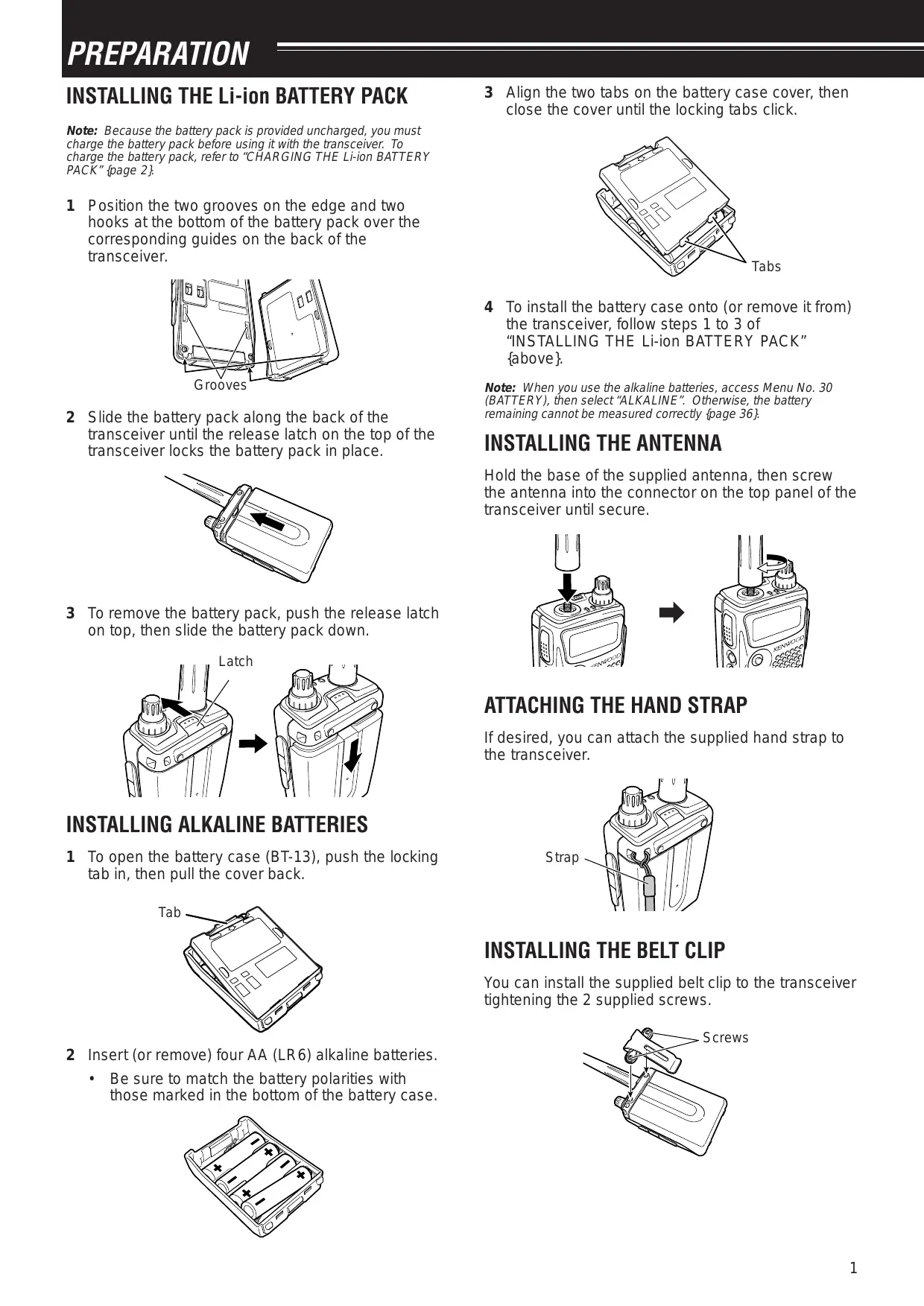
2 Slide the battery pack along the back of the transceiver until the release latch on the top of the transceiver locks the battery pack in place.
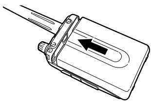
3 To remove the battery pack, push the release latch on top, then slide the battery pack down.
INSTALLING ALKALINE BATTERIES
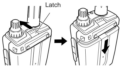
1 To open the battery case (BT-13), push the locking tab in, then pull the cover back.
2 Insert (or remove) four AA (LR6) alkaline batteries.
- Be sure to match the battery polarities with those marked in the bottom of the battery case.
3 Align the two tabs on the battery case cover, then close the cover until the locking tabs click.
4 To install the battery case onto (or remove it from) the transceiver, follow steps 1 to 3 of "INSTALLING THE Li-ion BATTERY PACK" {above}.
Note: When you use the alkaline batteries, access Menu No. 30 (BATTERY), then select "ALKALINE". Otherwise, the battery remaining cannot be measured correctly {page 36}.
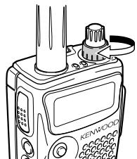
INSTALLING THE ANTENNA
Hold the base of the supplied antenna, then screw the antenna into the connector on the top panel of the transceiver until secure.
ATTACHING THE HAND STRAP
If desired, you can attach the supplied hand strap to the transceiver.
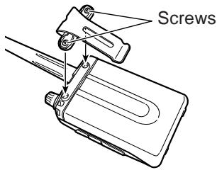
INSTALLING THE BELT CLIP
You can install the supplied belt clip to the transceiver tightening the 2 supplied screws.
1 PREPARATION
CHARGING THE Li-ion BATTERY PACK
The Li-ion battery pack can be charged after it has been installed onto the transceiver. The battery pack is provided uncharged for safety purposes.
1 Confirm that the transceiver power is OFF.
While charging the battery pack, leave the transceiver power OFF.
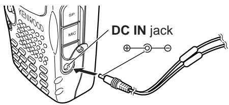
2 Insert the charger plug into the DC IN jack of the transceiver.
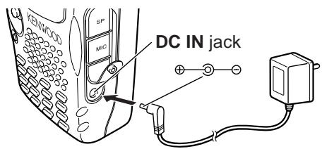
3 Plug the charger into an AC wall outlet.
- Charging starts and 2 LEDs on the top panel lights orange.
4 It takes approximately 6.5 hours to charge an empty PB-42L Li-ion battery pack. When charging completes, the LEDs unlight; remove the charger plug from the transceiver DC IN jack.
5 Unplug the charger from the AC wall outlet.
Note:
If you turn the transceiver ON and press [F], [LOW/BATT] while charging the battery pack, "CHARGING" appears. "STANDBY" appears when the charging completes.
The transceiver becomes warm while charging the battery pack.
If the charger plug is plugged into the DC IN jack before the battery pack is attached, turn the transceiver ON and then OFF again to initiate the charging.
CAUTION
Exceeding the specified charge period shortens the useful life of the Li-ion battery pack.
The provided charger is designed to charge only the provided PB-42L Li-ion battery pack. Charging other models of battery packs may damage the charger and battery pack.
Do not press [PTT] while charging.
The battery pack must be kept in cool and dry place.
Never leave the battery pack in the direct sun light.
CONNECTING TO A CIGARETTE LIGHTER SOCKET
To connect the transceiver to the cigarette lighter socket in your vehicle, use an optional PG-3J Cigarette Lighter cable.
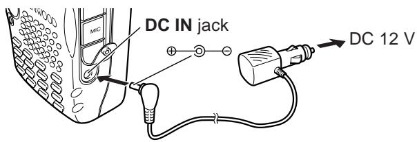
While the PG-3J is connected to the cigarette lighter plug, the transceiver automatically start charging the Li-ion battery pack (PB-42L). When you operate the transceiver, it charges the Li-ion battery pack in back
ground. If the transceiver is turned OFF, the 2 LEDs light orange while charging. When the charging completes, they turn OFF {above}.
CAUTION
To connect with an external 24 V power source via a DC-DC converter, only use the optional PG-3J Cigarette Lighter cable. Using the PG-2W DC cable in this situation may cause a fire.
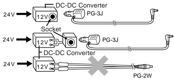
Note: If the input voltage exceeds approximately 16.5 V, warning beeps sound and "VOLTAGE ERROR" appears.
CONNECTING TO A REGULATED POWER SUPPLY
To connect the transceiver to an appropriate regulated power supply, use an optional PG-2W DC cable.
1 Confirm that the power of both the transceiver and the power supply are OFF.
2 Connect the optional PG-2W DC cable to the power supply; the red lead to the positive (+) terminal, and the black lead to the negative (-) terminal.
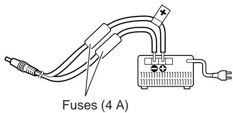
3 Connect the barrel plug on the DC cable to the DC IN jack of the transceiver.
If the transceiver is turned OFF while a regulated power supply is connected with the DC IN jack, it automatically initiates charging the Li-ion battery pack (PB-42L) {above}.
Note:
If the DC power supply voltage is below 12.0 V DC, you may not be able to charge the Li-ion battery pack (PB-42L).
The supply voltage must be between 12.0V and 16.0V to prevent damaging the transceiver. If input voltage exceeds approximately 16.5V , warning beeps sound and "VOLTAGE ERROR" appears. Remove the DC IN jack plug immediately.
If the DC power supply voltage is above 14.5 V DC and "H" (High Power) is selected, "H" icon blinks and the output power is reduced to "L" level (Low Power) automatically {page 41}.
FIRST QSO
Are you ready to give your transceiver a quick try? Reading this page should get your voice on the air right away. The instructions below are intended only for a quick guide. If you encounter problems or there is something you would like to know more, read the detailed explanations given later in this manual.
Press and hold [ 念 ] (POWER) briefly to switch the transceiver power ON.
- A high pitched double beep sounds and then "KENWOOD" and "HELLO !!" appear momentarily. The various indicators and 2 frequencies appear on the LCD.
- The transceiver stores the parameters when it is turned OFF. It automatically recalls these parameters next time you turn the transceiver ON again.
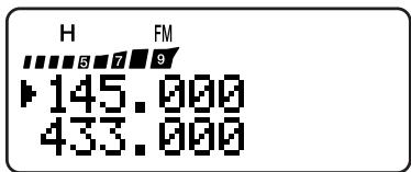
Press [A/B] to select the frequency band on top.
Each time you press [A/B], the “▶” icon moves, indicating which frequency band is currently selected for operation.

③ Turn the VOL control clockwise to the 11 o'clock position.
Press [BAND] until you select the amateur radio band you wish to operate.
⑤ Turn the Tuning control to select the receive frequency.
- You may further turn the VOL control to adjust the volume level of the signal.
To transmit, hold the transceiver approximately 5 cm (2 inches) from your mouth.
Press and hold the PTT switch, then speak in your normal tone of voice.
Release the PTT switch to receive.
Repeat steps 6, 7 and 8 to continue communication.
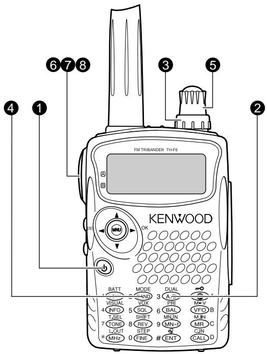
KEYS AND CONTROLS
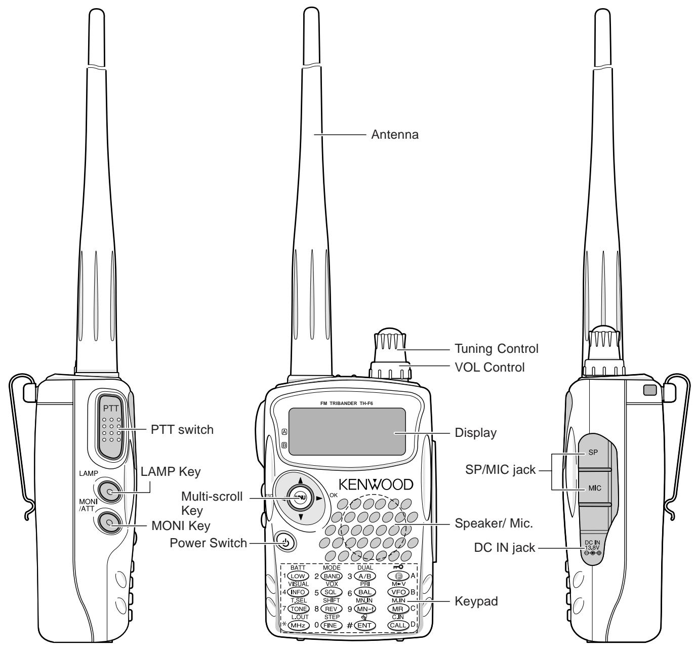
A/B-band status LEDs
Green:Busy
Red : Transmitting
Orange: Charging
DISPLAY
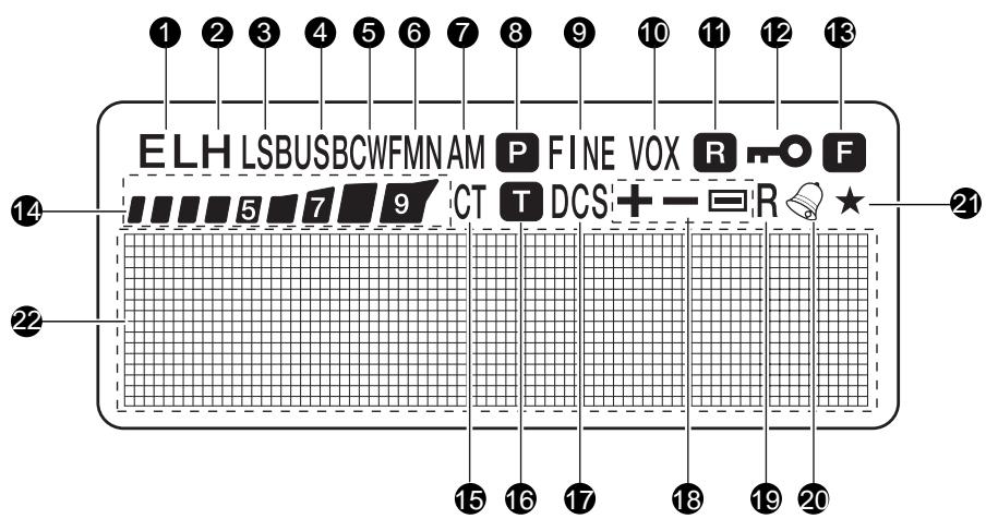
1 EL
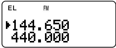
Appears when the transmit output power is set to Low ("L") or Economic Low ("EL") {pages 7, 41}.
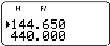
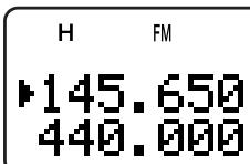
2 H
Appears when the transmit output power is set to High ("H") {pages 7, 41}.
③ LSB
Appears when lower side band (LSB) is selected for B-band {page 34}.
4 USB
Appears when upper side band (USB) is selected for B-band {page 34}.
CW
Appears when CW is selected for B-band {page 34}.
WFMN
"WFM" appears when wide FM mode is selected {page 34}. "FM" appears when normal FM mode is selected. "FMN" appears when narrow FM mode is selected {page 39}.
7 AM
"AM" appears when AM mode is selected {page 34}.
8 P
Appears when a Priority Scan is activated {page 25}.
9 FINE
Appears when a Fine Tuning function is activated {page 35}.
10 VOX
Appears when the VOX function is activated {page 41}.
11 R
Appears when the Automatic Simplex Check (ASC) is activated {page 14}.
12 m0
Appears when the Lock function is ON{page 38}.
13 F
Appears when the function key is pressed.
14 579
S-meter (RX) and relative RF power meter (TX).
15 CT
"CT" appears when the CTCSS function is activated {page 28}.
16 T
Appears when the Tone function is activated {page 13}.
DCS
Appears when the DCS function is activated {page 29}.
16 +/ -
Appears when the repeater shift function is activated {page 12}.
19 R
Appears when the Reverse function is activated {page 14}.
20
Appears when the Tone Alert function is activated {page 40}.
21
Appears when the displayed memory channel has been locked out {page 27}.
Dot-matrix display
76 x 16 dot-matrix display. It displays various information, such as the operating frequencies, menu settings, and etc.
3 GETTING ACQUAINTED
1 Press [ ] (POWER) briefly to switch the transceiver power ON.
- Upon power up, a high pitched double beep sounds, followed by the frequencies and other indicators.

2 To switch the transceiver OFF, press [ ] (POWER) again.
- When you turn the transceiver OFF, a low pitched double beep sounds.
- The transceiver stores the parameters when it is turned OFF. It recalls these parameters next time you turn the transceiver ON again.
ADJUSTING VOLUME
Turn the VOL control clockwise to increase the audio output level and counterclockwise to decrease the output level.
- If you are not receiving a signal, press and hold [MONI] to unmute the speaker, then adjust the VOL control to a comfortable audio output level.
ADJUSTING SQUELCH
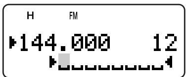
The purpose of the Squelch is to mute the speaker when no signals are present. With the squelch level correctly set, you will hear sound only while actually receiving signals. The higher the selected squelch level, the stronger the signals must be, to receive. The appropriate squelch level depends on the ambient RF noise conditions. You can configure independent threshold squelch levels for the A-band and B-band.
1 Press [SQL].
- The current squelch level appears.
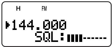
2 Turn the Tuning control or press [] / [] to adjust the level.
-
Select the level at which the background noise is just eliminated when no signal is present.
-
The higher the level, the stronger the signals must be, to receive.
- 6 different levels can be set -- -- -- --: level 0 ~ || || || || || level 5).
3 Press [▶] or [MNU] to store the new settings or press [▶] to cancel without changing the current setting.
Note: When operating in USB, LSB and CW modes, the squelch unmutes up to level 2.
SELECTING A BAND
By default, two frequencies are displayed on the LCD. The frequency on top is called the A-band. The bottom frequency is called the B-band.
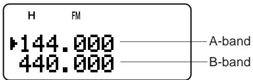
Press [A/B] to select the A-band or B-band for operation. Each time you press [A/B], the “▶” icon moves, indicating which band is currently selected for operation. Usually, select the A-band to operate the amateur band and select the B-band to receive the various broadcasting stations, such as AM, FM, TV (audio only) or another amateur band {page 33}.
MULTI-SCROLL KEY
This transceiver has a 4-way cursor key with a MENU ("MNU") key in the center.
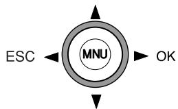
A/v keys
The / keys function in the same way as the Tuning control. These keys change the frequencies, memory channels, and other selections.
Note: You can use the Tuning control in place of the / keys for most of the controls.
OKkey
Press to move to the next step or complete the setting in various modes, such as Menu mode, CTCSS frequency selection, and DCS code selection.
/ ESC key
Press to move back or cancel the entry in various modes, such as Menu mode, CTCSS frequency selection, and direct frequency entry.
MNU key
Press to enter the Menu mode.
In Menu mode, you can select the desired menu number by turning the Tuning control or pressing [A]/[V]. It also functions as [OK] key.
TRANSMITTING
1 To transmit, hold the transceiver approximately 5 cm (2 inches) from your mouth, then press and hold the PTT switch and speak into the microphone in your normal tone of voice.
- The status LED on the top panel lights red and bar-graph meter appears.
- If you press [PTT] while you are outside of the transmission coverage, a high pitched error beep sounds.
2 When you finish speaking, release the PTT switch.
Note: If you transmit continuously for more than 10 minutes, the internal time-out timer generates a warning beep and the transceiver stops transmitting. In this case, release the PTT switch and let the transceiver cool down for a while, then press the PTT switch again to resume transmitting {pages 40, 51}.
Selecting Output Power
Selecting lower transmission power is the best way to reduce the battery consumption, if communication is still reliable. You can configure different power levels for transmission {page 41}.
Press [LOW].
Each time you press [LOW], the indicator cycles between "H" (high), "L" (low), and "EL" (economic low).
Note:
You can store different output power setting for the A and B-band.
When you change the output power, it is reflected to all available amateur bands for A or B-band.
SELECTING A FREQUENCY
VFO Mode
This is the basic mode for changing the operating frequency. Turn the Tuning control clockwise to increase the frequency. Turn the Tuning control counterclockwise to decrease the frequency. Or, press [▲]/[▼] to change the frequency.
MHz Mode
If the desired operating frequency is far away from the current frequency, it is quicker to use the MHz tuning mode.
To adjust the MHz digit:
1 Press [MHz].
- A MHz digit blinks.
2 Turn the Tuning control or press [A]/[V] to select the desired MHz digit.
3 After selecting the desired MHz digit, press [MHz] to exit the mode and return to normal VFO mode {above}.
4 You may further adjust the frequency using the Tuning control or [ ] / [ ]
Note: MHz mode does not function in AM band.
Direct Frequency Entry
In addition to turn the Tuning control or press [A]/[V], there is another way of selecting the frequency. When the desired frequency is far away from the current frequency, you can directly enter a frequency from the numeric keypad.
1 Press [VFO].
- You must be in the VFO mode to make the direct frequency entry.
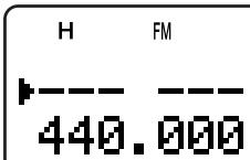
2 Press [ENT].
- "---" appears.
3 Press the numeric keys ([0] to [9]) to enter your desired frequency. [MHz] can be used to complete the MHz digits entry.
- Pressing [ENT] fills the remaining digits (the digits you did not enter) with 0 and completes the entry.
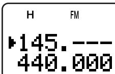
To select 145.000 MHz for example, press [1], [4], [5] then press [ENT] to complete the entry.
If you want to revise the MHz digits only, press [VFO] in place of [ENT].
3 GETTING ACQUAINTED
Example 1 (100 MHz < f < 1000 MHz)
To enter 438.320 MHz:
Key in Display
[ENT]
[4], [3], [8] 438. - - -
[3], [2], [0] 438.320
Note: You do not have to press [MHz] when you are entering 3-digit MHz number.
Example 2
To enter 439.000 MHz:
Key in Display
[ENT]
[4], [3], [9] 439. - - -
[ENT] 439.000
Example 3
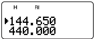
To revise 144.650 MHz to 145.650 MHz:
Key in Display 144.650
[ENT]
[1], [4], [5] 145. - - -
[VFO] 145.650
Example 4 (f > 1000 MHz)
To enter 1250.500 MHz (B-band only):
Key in Display
[ENT]
[1], [2], [5], [0] 1250. --
[5] 1250.5--
[ENT] 1250.500
Example 5 (f < 100 MHz)
To enter 10.500 MHz (B-band only):
Key in Display
[ENT]
[1], [0] 10- - - -
[MHz] 10. - - -
[5] 10.5--
[ENT] 10.5000
Note: When pressing the last [ENT], the Fine Tuning function is automatically activated for 10.5000 MHz.
Example 6
To enter 810kHz (B-band only):
Key in Display
[ENT]
[0] 0--
[MHz] 0. - - -
[8], [1], [0] 0.810
Note:
If the entered frequency does not match the current frequency step size, the frequency is automatically rounded down to the next available frequency.
When the desired frequency cannot be entered exactly, check whether the Fine Tuning function is ON or not {page 35}, and then confirm the frequency step size {page 37}.
Some frequency ranges are blocked, due to government regulations. Refer to the specifications {pages 53, 54} for the T/RX coverage.
If you turn the Tuning control or press [A]/[V] while entering the frequency, the transceiver clears the entry and recovers the previous frequency and mode.
WHAT IS A MENU?
Many functions on this transceiver are selected or configured via a software-controlled Menu, rather than through the physical controls of the transceiver. Once familiar with the Menu system, you will appreciate the versatility it offers. You can customize the various timings, settings, and programming functions on this transceiver to meet your needs without using many controls and switches.
MENU ACCESS
1 Press [MNU].
- The Menu No. and setting appear on the display, along with a brief explanation of the Menu No.
2 Turn the Tuning control or press [▲]/[▼] to select your desired Menu No. - As you change the Menu No., a brief explanation of each Menu No. appears.
3 Press [▶] or [MNU] to configure the parameter of the currently selected Menu No.
![KENWOOD TH-F7E - Press [MNU]. - 1](/content/2025/01/83302/images/1c00611abf34b96b6b1b98ad94536634a83aa6f946ca5d0420f81eaa0e20aa01.jpg)
4 Turn the Tuning control or press [] / [] to select your desired parameter.
5 Press [▶] or [MNU] to store the setting. Otherwise, press [←] or [PTT] to cancel.
MENUFUNCTIONLIST
| On the Display | Menu No. | Function | Selections | Default | Ref. Page |
| SCAN RESUME | 1 | Scan resume method TIME: Time-Operated mode CARRIER: Carrier-Operated mode SEEK: Seek and stop mode | TIME/ CARRIER/ SEEK | TIME | 27 |
| M.GRP LINK | 2 | Memory Group Link configuration | 0 1 2 3 4 5 6 7 | No Links | 24 |
| MR METHOD | 3 | Memory Recall condition | ALL BANDS/ CURRENT BAND | ALL BANDS | 16 |
| PROG VFO | 4 | Programmable VFO frequency range (A-band only) | — | See Reference Page | 39 |
| AUTO OFFSET | 5 | Auto Repeater Offset function | ON/ OFF | ON | 13 |
| OFFSET | 6 | Repeater offset frequency | 0.00 ~ 59.95 MHz in steps of 0.05 MHz | See Reference Page | 12 |
| TUNE ENABLE | 7 | Permit use of the Tuning control when the keys are locked | ON/ OFF | OFF | 38 |
| TX INHIBIT | 8 | Inhibit the transmission | ON/ OFF | OFF | 40 |
| SP/MIC JACK | 9 | Select the SP/MIC jack function | SP/MIC / TNC/ PC | SP/MIC | 45 46 |
SELECTING A MENU LANGUAGE
You can select either English or Japanese (Katakana) for the menu description. To switch the language:
1 Press [MNU].
2 Turn the Tuning control or press [▲]/[▼] to select Menu No. 27.
3 Press [▶] or [MNU].
4 Turn the Tuning control or press [▲]/[▼] to select either "ENGLISH" or "JAPANESE".

5 Press [▶] or [MNU] to store the setting. Otherwise, press [<] or [PTT] to cancel.
- When you select "JAPANESE" in step 3 and press [▶] or [MNU], all Menu explanations are displayed in Japanese (Katakana). To return to English mode, repeat step 1, 2 and 3 {above} to access Menu No. 27, then select "ENGLISH". Press [▶] or [MNU] to display the Menu mode in English.
Note: The menu language selection does not affect any other modes, such as memory name {page 17} or DTMF name {page 31}.
4 MENU SETUP
| On the Display | Menu No. | Function | Selections | Default | Ref. Page |
| DTMF STORE | 10 | Store DTMF numbers in DTMF memories | — | No Data | 31 |
| DTMF SPD | 11 | DTMF tone transmission speed | FAST/ SLOW | FAST | 32 |
| DTMF HOLD | 12 | Hold the transmission for 2 seconds between DTMF key entries | ON/ OFF | OFF | 31 |
| DTMF PAUSE | 13 | The pause duration while transmitting DTMF tones | 100/ 250/ 500/ 750/ 1000/ 1500/ 2000 ms | 500 ms | 32 |
| DTMF LOCK | 14 | Disable DTMF transmission with keys | ON/ OFF | OFF | 32 |
| PWR-ON MSG | 15 | Power-on message | 8 characters | HELLO !! | 39 |
| CONTRAST | 16 | LCD display contrast1: minimum ~ 16: maximum | 1 ~ 16 | 8 | 37 |
| BAT Saver | 17 | Battery saver receiver shut-off period | OFF/ 0.2/ 0.4/ 0.6/0.8/ 1.0/ 2.0/ 3.0/4.0/ 5.0 sec. | 1.0 sec. | 37 |
| APO | 18 | Automatic Power Off function | OFF/ 30/ 60 min. | 30 min. | 36 |
| KEY BEEP | 19 | Beep function | ON/ OFF | ON | 37 |
| VOXonBUSY | 20 | Allow VOX transmission when the receiver is busy | ON/ OFF | OFF | 42 |
| VOX GAIN | 21 | Set the VOX gain sensitivity0: least sentisive ~ 9: most sensitive | 0 ~ 9 | 4 | 41 |
| VOX DELAY | 22 | Adjust the VOX delay time | 250/ 500/ 750/1000/ 1500/ 2000/3000 ms | 500 ms | 41 |
| CALL KEY | 23 | Select a function for the CALL key | CALL/ 1750 Hz | CALL(TH-F6A)1750 Hz(TH-F7E) | 19 |
| 1750 HOLD | 24 | Hold the TX status when a 1750 Hz tone is transmitted | ON/ OFF | OFF | 13 |
| BEAT SHIFT | 25 | Shift the internal CPU clock frequency | ON/ OFF | OFF | 37 |
| BAR ANT | 26 | Enable an internal bar antenna below 10.1 MHz | ENABLED/ DISABLED | ENABLED | 34 |
| LANGUAGE | 27 | Select the menu language | ENGLISH/JAPANESE | ENGLISH | 9 |
| PACKET | 28 | Select an external TNC packet speed | 1200/ 9600 bps | 1200 bps | 45 |
| FM NARROW | 29 | FM narrow band operation | ON/ OFF | OFF | 39 |
| BATTERY | 30 | Select a battery type | LITHIUM/ALKALINE | LITHIUM | 36 |
| RESET? | 31 | Select a reset mode | NO/ VFO RESET/MENU RESET/FULL RESET | NO | 50 |
ALPHABETICAL FUNCTION LIST
| On the Display | Menu No. | Selections | Default | Ref. Page |
| APO | 18 | OFF/ 30/ 60 minutes | 30 min. | 36 |
| AUTO OFFSET | 5 | ON/ OFF | ON | 13 |
| BAR ANT | 26 | ENABLED/ DISABLED | ENABLED | 34 |
| BATTERY | 30 | LITHIUM/ ALKALINE | LITHIUM | 36 |
| BAT Saver | 17 | OFF/ 0.2/ 0.4/ 0.6/ 0.8/ 1.0/ 2.0/ 3.0/ 4.0/ 5.0 sec. | 1.0 sec. | 37 |
| BEAT SHIFT | 25 | ON/ OFF | OFF | 37 |
| CALL KEY | 23 | CALL/ 1750 Hz | CALL (TH-F7E)/ 1750 Hz (TH-F6A) | 19 |
| CONTRAST | 16 | 1 ~ 16 | 8 | 37 |
| DTMF HOLD | 12 | ON/ OFF | OFF | 31 |
| DTMF LOCK | 14 | ON/ OFF | OFF | 32 |
| DTMF PAUSE | 13 | 100/ 250/ 500/ 750/ 1000/ 1500/ 2000 ms | 500 ms | 32 |
| DTMF SPD | 11 | FAST/ SLOW | FAST | 32 |
| DTMF STORE | 10 | — | No Data | 31 |
| FM NARROW | 29 | ON/ OFF | OFF | 39 |
| KEY BEEP | 19 | ON/ OFF | ON | 37 |
| LANGUAGE | 27 | ENGLISH/ JAPANESE | ENGLISH | 9 |
| MR METHOD | 3 | ALL BANDS/ CURRENT BAND | ALL BANDS | 16 |
| M.GRP LINK | 2 | 0 1 2 3 4 5 6 7 | No Links | 24 |
| OFFSET | 6 | 0.00 ~ 59.95 MHz in steps of 0.05 MHz | See Reference Page | 12 |
| PACKET | 28 | 1200/ 9600 bps | 1200 bps | 45 |
| PROG VFO | 4 | — | — | 39 |
| PWR-ON MSG | 15 | 8 characters | HELLO !! | 39 |
| RESET? | 31 | NO/ VFO RESET/ MENU RESET/ FULL RESET | NO | 50 |
| SCAN RESUME | 1 | TIME/ CARRIER/ SEEK | TIME | 27 |
| SP/MIC JACK | 9 | SP/MIC / TNC/ PC | SP/MIC | 45, 46 |
| TUNE ENABLE | 7 | ON/ OFF | OFF | 38 |
| TX INHIBIT | 8 | ON/ OFF | OFF | 40 |
| VOX DELAY | 22 | 250/ 500/ 750/ 1000/ 1500/ 2000/ 3000 ms | 500 ms | 41 |
| VOX GAIN | 21 | 0 ~ 9 | 4 | 41 |
| VOXonBUSY | 20 | ON/ OFF | OFF | 42 |
| 1750 HOLD | 24 | ON/ OFF | OFF | 13 |
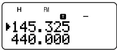
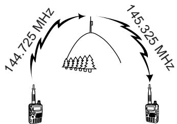
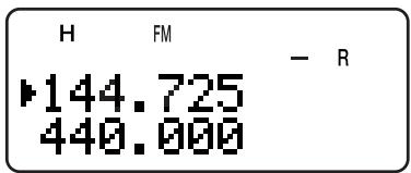
Repeaters, which are often installed and maintained by radio clubs, are usually located on mountain tops or other elevated locations. Generally they operate at higher ERP (Effective Radiated Power) than a typical station. This combination of elevation and high ERP allows communications over much greater distances than communications without using repeaters.
Most repeaters use a receive and transmit frequency pair with a standard or non-standard offset (odd-split). In addition, some repeaters must receive a tone from the transceiver to allow it to access. For details, consult your local repeater reference.
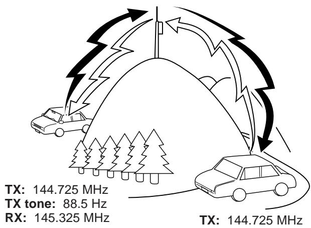
TX: 144.725 MHz
TX tone: 88.5 Hz
RX: 145.325 MHz
OFFSET PROGRAMMING FLOW
1 Select a band.
Select a receive frequency.
3 Select an offset direction.
4 Select an offset frequency. (only when programming odd-split repeater frequencies)
Activate the Tone function. (If necessary)
Select a tone frequency. (If necessary)
If you store the above data in a memory channel, you need not reprogram every time. See "MEMORY CHANNELS" {page 15}.
PROGRAMMING OFFSET
First select an amateur radio repeater downlink frequency on the A-band or B-band as described in "SELECTING A FREQUENCY" {page 7}.
Selecting Offset Direction
Select whether the transmit frequency will be higher (+) or lower (-) than the receive frequency.
Press [F], [REV] to select the offset direction.
- “+” or “-” appears, indicating which offset direction is selected.
- To program -7.6MHz offset on the TH-F7E (430 MHz only), repeatedly press [F], [REV] until “ ” appears.
If the offset transmit frequency falls outside the allowable range, transmitting is inhibited. In this case, adjust the receive frequency so that the transmit frequency is within the band limits.
Note: While using an odd-split memory channel or transmitting, you cannot change the offset direction.
Selecting Offset Frequency
To access a repeater which requires an odd-split frequency pair, change the offset frequency from the default which is used by most repeaters. The default offset frequency on the 2m band is 600 kHz (all models); the default on the 70 cm band is 5.0 MHz (TH-F6A) or 1.6 MHz (TH-F7E); the default on the 1.25 m band is 1.6 MHz (TH-F6A).
1 Press [BAND] to select an amateur radio band you want to change the offset frequency.
2 Press [MNU].
3 Turn the Tuning control or press [▲]/[▼] to select Menu No. 6 (OFFSET).
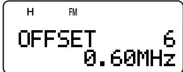
4 Press [▶] or [MNU].
5 Turn the Tuning control or press [] / [] to select the appropriate offset frequency.
- The selectable range is from 0.00 MHz to 59.95 MHz in steps of 50 kHz.
6 Press [▶] or [MNU] to store the setting. Otherwise, press [PTT] to cancel.
TH-F7E only: If you have selected " " for the offset direction, you cannot change the default (-7.6 MHz) offset frequency.
Note: After changing the offset frequency, the new offset frequency will also be used by Automatic Repeater Offset.
Activating Tone Function
Press [TONE] to switch the Tone function ON (or OFF).
- “T” appears when the Tone function is ON.
Note: You cannot use the Tone and CTCSS/ DCS functions at the same time. Switching the Tone function ON after activating the CTCSS/ DCS deactivates the CTCSS/ DCS function.
TH-F7E only: When you access repeaters that require 1750 Hz tones, you need not activate the Tone function. Press [CALL] without pressing the PTT switch to transmit a 1750 Hz tone (default setting).
Selecting a Tone Frequency
1 While the Tone function is ON, press [F], [TONE].
2 Turn the Tuning control or press [] / [] to select the desired tone frequency.

3 Press [▶] or [MNU] to complete the setting. Otherwise, press [PTT] to cancel.
Available Tone Frequencies
| No. | Freq. (Hz) | No. | Freq. (Hz) | No. | Freq. (Hz) | No. | Freq. (Hz) |
| 01 | 67.0 | 12 | 97.4 | 23 | 141.3 | 34 | 206.5 |
| 02 | 69.3 | 13 | 100.0 | 24 | 146.2 | 35 | 210.7 |
| 03 | 71.9 | 14 | 103.5 | 25 | 151.4 | 36 | 218.1 |
| 04 | 74.4 | 15 | 107.2 | 26 | 156.7 | 37 | 225.7 |
| 05 | 77.0 | 16 | 110.9 | 27 | 162.2 | 38 | 229.1 |
| 06 | 79.7 | 17 | 114.8 | 28 | 167.9 | 39 | 233.6 |
| 07 | 82.5 | 18 | 118.8 | 29 | 173.8 | 40 | 241.8 |
| 08 | 85.4 | 19 | 123.0 | 30 | 179.9 | 41 | 250.3 |
| 09 | 88.5 | 20 | 127.3 | 31 | 186.2 | 42 | 254.1 |
| 10 | 91.5 | 21 | 131.8 | 32 | 192.8 | ||
| 11 | 94.8 | 22 | 136.5 | 33 | 203.5 |
Note: 42 different tones are available for the transceiver. These 42 tones include 37 EIA standard tones and 5 non-standard tones.
TH-F7E only:
To transmit a 1750Hz tone, simply press [CALL] without pressing the PTT switch (default setting). Release [CALL] to quit transmitting. You can also make the transceiver remain in the transmit mode for 2 seconds after releasing [CALL]; a 1750Hz tone is not continuously transmitted. Access Menu No. 24 (1750 HOLD) and select "ON".
If you desire to assign [CALL] for recalling the Call channel in place of transmitting the 1750 Hz tone, access Menu No. 23 (CALL KEY) and select "CALL".
AUTOMATIC REPEATER OFFSET
This function automatically selects an offset direction, according to the frequency that you select on the 2 m and 1.25 m (TH-F6A only) bands. The transceiver is programmed for offset direction as shown below. To obtain an up-to-date band plan for repeater offset direction, contact your national Amateur Radio association.
TH-F6A (U.S.A. and Canada)
This complies with the standard ARRL band plan.
S: Simplex
| 144.0 | 145.5 | 146.4 | 147.0 | 147.6 | |||
| 145.1 | 146.0 | 146.6 | 147.4 | 148.0 MHz | |||
| S | - | S | + | S | - | + | S |
S: Simplex
| 222.0 | 223.920 | 225.0 MHz |
| S | - |
TH-F7E (Europe/Others)
S: Simplex
| 144.0 S | - | S |
Note: Automatic Repeater Offset does not function when Reverse is ON. However, pressing [REV] after Automatic Repeater Offset has selected an offset (split) status, exchanges the receive and transmit frequencies.
1 Press [MNU].
2 Turn the Tuning control or press [▲]/[▼] to select Menu No. 5 (AUTO OFFSET).
3 Press [▶] or [MNU].
4 Turn the Tuning control or press [▲]/[▼] switch the function ON or OFF.

5 Press [▶] or [MNU] to store the setting. Otherwise, press [PTT] to cancel.
Note: If you select the frequency within the amateur radio band on the B-band, the Automatic Repeater Offset function is also activated in any modes.
5 OPERATING THROUGH REPEATERS
REVERSE FUNCTION
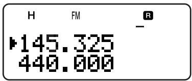
The reverse function exchanges a separate receive and transmit frequency. So, while using a repeater, you can manually check the strength of a signal that you receive directly from the other station. If the station's signal is strong, both stations should move to a simplex frequency and free up the repeater.
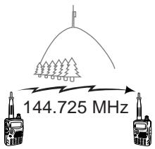
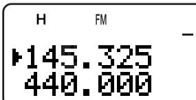
TX: 144.725 MHz TX: 144.725 MHz TX: 144.725 MHz RX: 145.325 MHz RX: 145.325 MHz RX: 145.325 MHz RX: 144.725 MHz
To swap the transmit and receive frequencies:
Press [REV] to switch the Reverse function ON (or OFF).
- "R" appears when the function is ON.
Note: You can turn the Reverse function ON when you are operating in Simplex mode. However, it does not change the TX/ RX frequency.
AUTOMATIC SIMPLEX CHECK (ASC)
While using a repeater, the ASC function periodically checks the strength of a signal that you are receiving directly from the other station. If the station's signal is strong enough to allow direct contact without a repeater, “R” indicator on the display starts blinking.
Press [REV] (1 s) to switch the function ON.
- “R” appears when the function is ON.
While direct contact is possible, "R" blinks.
To quit the function, press [REV].
Note:
Pressing the PTT switch causes "R" icon to quit blinking.
ASC can be activated while operating in Simplex mode. However, it does not change the TX/ RX frequencies.
ASC does not function while scanning.
Activating ASC while using Reverse switches Reverse OFF.
If you recall a memory channel or the Call channel that contains a Reverse ON status, ASC is switched OFF.
ASC causes received audio to be momentarily intermitted every 3 seconds.
ASC does not function when the band is not selected for operation.
TONE FREQ. ID SCAN
This function scans through all tone frequencies to identify the incoming tone frequency on a received signal. You may use the function to find which tone frequency is required by accessing your local repeater.
1 While the Tone function is ON, press [F], [TONE] (1 s) to start the Tone Freq. ID scan.
- When the transceiver receives the signal, the scan starts.

Note: Some repeaters do not re-transmit the access tone in the downlink signal. In this case, check the other station's uplink signal to detect the repeater access tone.
- To reverse the scan direction, turn the Tuning control or press [▲]/[▼].
To quit the function, press [PTT] or [] . - When the tone frequency is identified, a beep sounds and the identified frequency appears.
2 Press [▶] to program the identified frequency in place of the current tone frequency.
- Press [<] if you do not want to program the identified frequency.
- Press [▲]/[▼] while the identified frequency is blinking, to resume scanning.
In memory channels, you can store frequencies and related data that you often use. Then you need not reprogram those data every time. You can quickly recall a programmed channel through simple operation. A total of 400 memory channels are available for storing the frequencies, modes and other operating conditions of the A and B-bands.
SIMPLEX & REPEATER OR ODD-SPLIT MEMORY CHANNEL?
You can use each memory channel as a simplex & repeater channel or an odd-split channel. Store only one frequency to use as a simplex & repeater channel or two separate frequencies to use as an odd-split channel. Select either application for each channel depending on the operations you have in mind.
Simplex & repeater channels allow:
- Simplex frequency operation
- Repeater operation with a standard offset (if an offset direction is stored)
Odd-split channels allow:
- Repeater operation with a non-standard offset
Note: Not only can you store data in memory channels, but you can also overwrite existing data with new data.
The data listed below can be stored in each memory channel:
| Parameter | Simplex & Repeater | Odd-Split |
| Receive frequency | Yes | Yes |
| Transmit frequency | Yes | |
| Tone frequency | Yes | Yes |
| Tone ON | Yes | Yes |
| CTCSS frequency | Yes | Yes |
| CTCSS ON | Yes | Yes |
| DCS code | Yes | Yes |
| DCS ON | Yes | Yes |
| Offset direction | Yes | N/A |
| Offset frequency | Yes | N/A |
| Reverse ON | Yes | N/A |
| Frequency step size | Yes | Yes |
| Memory channel lockout | Yes | Yes |
| Memory channel name | Yes | Yes |
| FINE tuning ON | Yes | Yes |
| Mode selection | Yes | Yes |
Yes: Can be stored in memory.
N/A: Cannot be stored in memory.
Note: The transmit frequency must be on the same band as the receive frequency band (Odd-split channel).
STORING SIMPLEX FREQUENCIES OR STANDARD REPEATER FREQUENCIES
1 Press [VFO].
2 Turn the Tuning control or press [▲]/[▼] to select your desired frequency in the amateur radio bands.
- You can also directly enter desired frequency using the keypad {page 7}.
3 If storing a standard repeater frequency, select the following data:
- Offset direction {page 12}
- Tone function, if necessary {page 13}
CTCSS/ DCS function, if necessary {pages 28, 29}
If storing a simplex frequency, you may select other related data (CTCSS or DCS settings, etc.).
4 Press [F].
- A memory channel number appears and blinks.
- "F" indicates the current channel is empty; "F" appears if the channel contains data.
- Memory channel number L0/U0 ~ L9/U9 {page 23}, I-0 ~ I-9 {page 20}, and Pr1 and Pr2 {page 25} are reserved for other functions.
5 Turn the Tuning control or press [▲]/[▼] to select the memory channel in which you want to store the data.
6 Press [MR] ([▶] or [MNU]) to store the data to the channel.
STORING ODD-SPLIT REPEATER FREQUENCIES
Some repeaters use a receive and transmit frequency pair with a non-standard offset. If you store two separate frequencies in a memory channel, you can operate on those repeaters without programming the offset frequency and direction.
1 Store the desired receive frequency and related data by the procedure given for simplex or standard repeater frequencies {above}.
2 Turn the Tuning control or press [▲]/[▼] to select the desired transmit frequency.
3 Press [F].
4 Turn the Tuning control or press [▲]/[▼] to select the memory channel you programmed in step 1.
5 Press [PTT]+[MR] ([PTT]+[or [PTT]+[MNU]).
- The transmit frequency is stored in the memory channel.
Note:
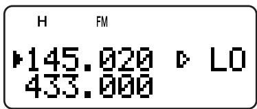
When you recall an odd-split memory channel, “+” and “-” appear on the display. To confirm the transmit frequency, press [REV].
When you revise only the transmission frequency for the odd-split channel, the frequency step size must be the same as the original odd-split channel memory data.
6 MEMORY CHANNELS
RECALLING A MEMORY CHANNEL
There are 2 ways of recalling the desired memory channel.
Using the Tuning Control or / Keys
1 Press [MR] to enter Memory Recall mode.
- The memory channel used last is recalled.
2 Turn the Tuning control or press [▲]/[▼] to select your desired memory channel.
- You cannot recall an empty memory channel.
To restore VFO mode, press [VFO].
Note: If the "CURRENT BAND" is selected for Menu No. 3 (MR METHOD), only memory channels that have the same band data can be recalled {below}.
Using a Numeric Keypad
You can also recall a memory channel by entering a desired memory channel number with the keypad.
1 Press [MR] to enter Memory Recall mode.
2 Press [ENT], then enter the channel number using 3 digits.
- For example, to recall channel 12, press [ENT], [0], [1], [2].
- You can shorten the entry for memory channels that are less than 100 by pressing [ENT] after entering the channel number. For example, to recall memory channel 9, press [ENT], [9], [ENT].
Note:
You cannot recall an empty memory channel. An error beep sounds.
You cannot recall the Program Scan memory channels (L0/U0 ~ L9/U9), Priority channels (Pr1 and Pr2), and Information Channels (I-0 ~ I-9), using the numeric keypad.
When you recall an odd-split memory channel, “+” and “-” appear on the display. Press [REV] to display the transmit frequency.
After recalling a memory channel, you may modify data such as Tone or CTCSS. These settings, however, are cleared once you select another channel or the VFO mode. To permanently store the data, overwrite the channel contents {page 15}.
CLEARING A MEMORY CHANNEL
To clear an individual memory channel:
1 Recall the memory channel you want to erase.
2 Press and hold [ ] (POWER) to switch the transceiver OFF.
3 Press [MR] + [] (POWER).
- An erase confirmation message appears.

4 Press [MR] ([▶] or [MNU]) to erase the channel data.
- The contents of the memory channel are erased.
- To quit clearing the memory channel, press any key other than [MR], [▶] and [MNU].
Note:
If you clear the information channel data, the data will be set to the factory default values.
You can also clear the Priority channel data and L0/U0 ~ L9/U9 data.
To clear all memory channels contents, perform the Full Reset {page 50}.
MEMORY RECALL MODE
Since the transceiver has more than 400 memory channels, it sometimes takes time to search for your desired memory channel. By default, the transceiver can recall all memory channels when [MR] is pressed, regardless of the current operating band. However, you can configure the transceiver to recall only the memory channels that have the same band information. For example, when you operate on the 2m band in VFO mode, pressing [MR] recalls only the memory channels that have 2m band information. To change the memory recall mode:
1 Press [MNU].
2 Turn the Tuning control or press [▲]/[▼] to select Menu No. 3 (MR METHOD).
3 Press [▶] or [MNU].
4 Turn the Tuning control or press [] / [] to select "CURRENT BAND".
5 Press [▶] or [MNU] to store the setting. Otherwise, press [←] or [PTT] to cancel.
When you press [MR] in VFO mode, only memory channels that have the same band data are recalled. To return to the default memory recall mode, repeat step 1 to 5 {above} and select "ALL BANDS" in step 4.
Note:
All Information Channels are recalled regardless of Memory Recall mode selection.
Memory Recall mode selection does not change the Memory Group scan channels {page 24}.
NAMING A MEMORY CHANNEL
You can name memory channels using up to 8 alphanumeric characters. When you recall a named memory channel, its name appears on the display in place of the stored frequency. Names can be call signs, repeater names, cities, names of people, etc.
1 Press [MR] to recall your desired memory channel.
2 Press [F], [MN<->f] to enter memory name input mode.
The entry cursor appears.
3 Turn the Tuning control or press [A]/[V] to select the first character.
- You can enter alphanumeric characters plus special ASCII characters. Refer to the following table for the available characters.
- Press [MONI] to delete the character at the cursor position.
- You can also use the numeric keypad to enter a character (Special ASCII characters are not available). For example, each press of [2] switches entry as a, b, c, 2, A, B, C and then back to a.
While pressing and holding [LAMP], turn the Tuning control to jump to the first character of each ASCII character group.
4 Press [▶].
- The cursor moves to the next digit.
5 Repeat steps 3 and 4 to enter up to 8 digits.
- Pressing [▶] after selecting the 8th digit completes the programming.
- To complete programming before entering less than 8 digits, press [MNU] or press twice.
- Press [←] to move the cursor back.
- Press [PTT] ([F], [VFO], [MR], or [CALL]) to cancel the entry.
After storing a memory name, pressing [MN<-->f] switches the display between the memory name and the frequency.
Note:
You can also name the DTMF memory channels {page 31} and Information Channels {page 20} but you cannot name the Call channel {page 19}.
You cannot assign a memory name to a channel that does not contain data.
You can overwrite stored names by repeating steps 1 to 5.
The stored name is erased when you clear the memory channel data.
Available Characters Using the Tuning Control
| Available Characters | |||||||||
| A | B | C | D | E | F | G | H | I | J |
| K | L | M | N | O | P | Q | R | S | T |
| U | V | W | X | Y | Z | [ | ] | ^ | _ |
| ` | a | b | c | d | e | f | g | h | i |
| j | k | l | m | n | o | p | q | r | s |
| t | u | v | w | x | y | z | { | | | } |
| ~ | \ | SP | ! | " | # | $ | % | & | ' |
| ( | ) | * | + | , | - | . | / | 0 | 1 |
| 2 | 3 | 4 | 5 | 6 | 7 | 8 | 9 | : | ; |
| < | = | > | ? | @ | |||||
| Additional Characters for the TH-F7E | |||||||||
| À | Á | À | Á | Ä | À | Æ | Ç | È | É |
| Ê | ë | ì | Í | Î | ï | Ø | Ñ | Ó | Ó |
| Ó | Ó | Ö | ð | ø | Ü | Ü | Ü | Ü | Y |
| Š | β | ÖE | à | á | ã | ã | ä | à | æ |
| ç | è | é | ê | ë | ì | í | í | ü | ð |
| ñ | ò | ó | ô | ö | ö | øe | ø | ù | ú |
| ú | ü | ý | Ö | þ | |||||
Available Characters Using the Numeric Keypad
| DTMF Key | Available Characters | ||||||
| 1 | q | z | 1 | Q | Z | ||
| 2 | a | b | c | 2 | A | B | C |
| 3 | d | e | f | 3 | D | E | F |
| 4 | g | h | i | 4 | G | H | I |
| 5 | j | k | l | 5 | J | K | L |
| 6 | m | n | o | 6 | M | N | O |
| 7 | p | r | s | 7 | P | R | S |
| 8 | t | u | v | 8 | T | U | V |
| 9 | w | x | y | 9 | W | X | Y |
| 0 | space | 0 | |||||
| # | ? | ! | ' | . | , | - | / |
| & | # | ( | ) | < | > | ; | |
| : | " | @ | |||||
6 MEMORY CHANNELS
MEMORY CHANNEL GROUPS
400 memory channels have been divided into 8 groups of 50. Group 0 contains memory channel numbers 0 49 , group 1 is 50 99 , group 2 is 100 149 , and so on. You can categorize each group to store similar data, same frequency bands or same modes for ease of use.
| Group # | Memory Channel | Group # | Memory Channel |
| Group 0 | 0 ~ 49 | Group 4 | 200 ~ 249 |
| Group 1 | 50 ~ 99 | Group 5 | 250 ~ 299 |
| Group 2 | 100 ~ 149 | Group 6 | 300 ~ 349 |
| Group 3 | 150 ~ 199 | Group 7 | 350 ~ 399 |
RECALLING A MEMORY CHANNEL USING MEMORY GROUP FUNCTION
It is sometimes a tedious endeavor to scroll through 400 memory channels sequentially. However, using a Group memory recall function, you can access your desired memory channel numbers more quickly.
1 Press [MR] to enter Memory Recall mode.
2 While pressing and holding [LAMP], turn the Tuning control to select a group.
Each click of the Tuning control, the lowest memory channel number of each group is recalled. For example, if you have the following memory channels that contain data:
| Group # | Memory Channels that Contain Data | |||||
| Group 0 | 0 | 2 | 10 | 15 | 30 | 45 |
| Group 1 | 50 | 61 | 65 | 78 | 98 | |
| Group 2 | 103 | 111 | 123 | |||
| Group 3 | 152 | 166 | ||||
| Group 4 | ||||||
| Group 5 | 260 | 280 | ||||
| Group 6 | 305 | 322 | 333 | 345 | ||
| Group 7 | 399 | |||||
Memory channels 0, 50, 103, 152, 260, 305, 399, and then 0 are recalled sequentially while pressing and holding [LAMP].
3 Release [LAMP] and turn the Tuning control to select the desired memory channels within the selected group.
Note: If you have configured Menu No. 3 (MR METHOD) as "CURRENT BAND" {page 16}, only memory channels that have the same frequency band data are recalled.
ERASING MEMORY CHANNELS USING MEMORY GROUP DELETE FUNCTION
Instead of erasing each unnecessary channel one by one, you can erase an entire group of memory channels at once. For example, if you erase group 2 memory channels, all the data in memory channels 100 149 are erased.
1 Press [MR].
- Turn the Tuning control or press [] / [] to select a memory channel in the group you want to erase (for example, memory channel No. 111, in Group 2).
2 Press [ 日 ] (POWER) to turn the transceiver OFF.
3 Press [MHz] + [ ] (POWER).
- An erase confirmation message appears.

4 Press [MR] ([▶] or [MNU]) to proceed. Otherwise, press any other key to cancel the erase.
MEMORY CHANNEL TRANSFER MEMORY VFO TRANSFER
After retrieving frequencies and associated data from Memory Recall mode, you can copy the data to the VFO. This function is useful, for example, when the frequency you want to monitor is near the frequency stored in a memory channel.
1 Press [MR], then turn the Tuning control to recall a desired memory channel.
2 Press [F], [VFO] to copy the memory channel data to the VFO.
Note:
To copy an odd-split channel data {page 15}, turn the Reverse function ON {page 14} before performing the transfer.
You can also transfer the Program Scan memory channels (L0 / U0 L9 / U9) , Priority Channels (Pr1 and Pr2), and Information Channels (I - 0 I - 9) to the VFO.
CHANNEL CHANNEL TRANSFER
You can also copy channel information from one memory channel to another. This function is useful when storing frequencies and associated data that you temporarily change in Memory Recall mode.
1 Press [MR], then turn the Tuning control to recall a desired memory channel.
2 Press [F].
3 Select the memory channel where you would like the data copied, using the Tuning control.
4 Press [MR] ([▶] or [MNU]).
| Channel 0 ~ 399 | → | Channel 0 ~ 399 |
| Receive frequency | → | Receive frequency |
| Transmit frequency | → | Transmit frequency |
| Tone frequency | → | Tone frequency |
| Offset direction | → | Offset direction |
| CTCSS frequency | → | CTCSS frequency |
| DCS code | → | DCS code |
| Tone/ CTCSS/ DCS ON/ OFF status | → | Tone/ CTCSS/ DCS ON/ OFF status |
| Offset frequency | → | Offset frequency |
| Reverse ON | → | Reverse ON |
| Frequency step size | → | Frequency step size |
| Memory channel name | → | Memory channel name |
| Fine Tuning ON | → | Fine Tuning ON |
| Mode selection | → | Mode selection |
| Memory Channel Lockout ON/ OFF | → | Memory Channel Lockout ON/ OFF |
| Channel 0 ~ 399 | → | L0/U0 ~ L9/U9, Pr1, Pr2 and I-0 ~ I-9 |
| Receive frequency | → | Receive frequency |
| Transmit frequency | → | Transmit frequency |
| Tone frequency | → | Tone frequency |
| Offset direction | → | Offset direction |
| CTCSS frequency | → | CTCSS frequency |
| DCS code | → | DCS code |
| Tone/ CTCSS/ DCS ON/ OFF status | → | Tone/ CTCSS/ DCS ON/ OFF status |
| Offset frequency | → | Offset frequency |
| Reverse ON | → | Reverse ON |
| Frequency step size | → | Frequency step size |
| Memory channel name | → | Memory channel name |
| Fine Tuning ON | → | Fine Tuning ON |
| Mode selection | → | Mode selection |
| Memory Channel Lockout ON | → | Memory Channel Lockout OFF |
The tables above illustrate how data is transferred between memory channels.
Note: When transferring an odd-split channel, the Reverse status, Offset direction, and Offset frequency are not transferred {page 15}.
CALL CHANNEL
The Call channel can be recalled instantly no matter what frequency the transceiver is operating on. For instance, you may use the Call channel as an emergency channel within your group. In this case, the Call Scan {page 25} will be useful.
The default Call channel frequencies are 144.000 MHz for the 2 m band, 223.000 MHz for 1.25 m band (TH-F6A), 430.000 MHz (TH-F7E)/ 440.000 MHz (TH-F6A) for the 70 cm band. Each Call channel can be reprogrammed either as a simplex or odd-split channel.
Note: Unlike Memory channels 0 to 399, the Call channel cannot be cleared. Clearing the Call channel will set it to the factory default values.
RECALLING THE CALL CHANNEL
1 Press [BAND] to select an amateur radio band.
2 Press [CALL] to recall the Call channel for that operating band.
- The Call channel frequency and "C" appear.
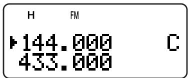
- To return to the previous frequency, press [CALL] again.
REPROGRAMMING THE CALL CHANNEL
1 Press [BAND] to select your desired amateur radio band.
2 Select your desired frequency and related data (Tone, CTCSS, DCS, or offset direction, etc.).
- When you program the Call channel as an odd-split channel, select a receive frequency first.
3 Press [F], [CALL].
- The selected frequency and related data are stored in the Call channel for the selected band.
To also store a separate transmit frequency, continue with the following steps.
4 Select the desired transmit frequency.
5 Press [F].
6 Press [PTT]+[CALL].
- The separate transmit frequency is stored in the Call channel.
Note:
The transmit frequency must be on the same band as the receive frequency band.
Call channel data is shared between the A and B-band.
The Reverse status cannot be not stored in the Call channel.
When you recall an odd-split Call channel, “+” and “-” appear on the display.
Transmit offset status and Reverse status are not stored in an odd-split Call channel.
When you revise only the transmission frequency for the odd-split Call channel, the frequency step size must be the same as the original odd-split Call channel memory data.
6 MEMORY CHANNELS
INFORMATION CHANNELS
10 Information channels are available for storing radio broadcasting service frequencies, such as weather radio stations and community FM broadcasting stations. For your conveniences, pressing [INFO] instantly recalls the Information channel to B-band. The following frequency data is stored by default.
| Channel Number | Frequency/ Mode/ Memory Name | |
| TH-F6A | TH-F7E | |
| I-1 | 162.550 MHz/ FM/ WEATHER | No data (Empty) |
| I-2 | 162.400 MHz/ FM/ WEATHER | |
| I-3 | 162.475 MHz/ FM/ WEATHER | |
| I-4 | 162.425 MHz/ FM/ WEATHER | |
| I-5 | 162.450 MHz/ FM/ WEATHER | |
| I-6 | 162.500 MHz/ FM/ WEATHER | |
| I-7 | 162.525 MHz/ FM/ WEATHER | |
| I-8 | 161.650 MHz/ FM/ WEATHER | |
| I-9 | 161.775 MHz/ FM/ WEATHER | |
| I-0 | 163.275 MHz/ FM/ WEATHER | |
You can revise the default channel data, such as the receiving frequencies, modes, and memory names.
RECALLING AN INFORMATION CHANNEL
Press [INFO] to recall the Information channels.
- "I-n" appears, where "n" represents the Information channel number from "0" ~ "9".

- If the B-band is selected for operation, you can turn the Tuning control or press [A]/[V] to select other Information channels. If the A-band is selected for operation, press [A/B] to move the operation band to the B-band and then select a different Information channel.
- To exit the Information channel mode, press [A/B] to select the B-band then press [VFO] or [MR].
Note: If you press [MN<>f], you can display the receiving frequency in place of the memory name.
TH-F7E only: As default, no frequency data is stored in the Information channel. Store the frequency data before using the Information channels. Otherwise, an error beep sounds.
REPROGRAMMING THE INFORMATION CHANNEL
1 Press [VFO].
2 Select a desired frequency and mode.
3 Press [F].
4 Turn the Tuning control or press [A]/[V] to select the memory channel (I-0 to I-9) in which you want to store the data.
5 Press [MR] ([▶] or [MNU]).
- A long beep sounds and the Information channel data is now revised.
Note:
When you perform the Full reset {page 50}, all the Information channels recover the factory default values.
If you clear an Information Channel data {page 16}, the factory default value is recovered.
You can also transfer the Information Channel data to the VFO or another memory channel.
CHANNEL DISPLAY
While in this mode, the transceiver displays only memory channel numbers (or memory names if stored) instead of frequencies.
1 Press [A / B] + [] (POWER).
- The transceiver displays the memory channel number in place of the operating frequencies.
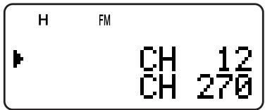
2 Turn the Tuning control or press [] / [] to select your desired memory channel number.
While in the Channel Display mode, only the following keys can be operated.
[KEY]
| LAMP | MONI | LOW | BAND | A/B | INFO |
| SQL | BAL | REV | ENT | F | MR |
| CALL1 | PTT | ▲ | ▼ | ▲ | ▲ |
| Tuning control | ∅ | ||||
1 When the "1750" is selected for the CALL key.
[F] then
| LAMP1 | LOW | A/B | ENT | F |
1 The light stays ON until the key is pressed again.
[KEY] (1 s)
| LAMP | INFO | MHz | F | MR |
While transmitting:
| LAMP | MNU | 1 | 2 | 3 | 4 |
| 5 | 6 | 7 | 8 | 9 | 0 |
| * | # | A | B | C | D |
When the transceiver is turned OFF, [ ] (POWER) and
| A/B | F |
To recover normal operation, turn the transceiver OFF and press [A / B] + [] (POWER) again.
Note:
To enter the Channel Display mode, you must have at least one memory channel that contains the data.
If the memory channel contains the memory name data, the memory name is displayed in place of the "CH" characters.
Scan is a useful function for hands-off monitoring of your favorite frequencies. By becoming comfortable with all types of Scan, you will increase your operating efficiency.
This transceiver provides the following types of scans.
| Scan Type | Purpose | |
| Normal Scan | Band Scan | Scans the entire band of the frequency you selected |
| Program Scan | Scans the specified frequency ranges stored in Memory channels L0/U0 ~ L9/U9 | |
| MHz Scan | Scans the frequencies within a 1 MHz range | |
| Memory Scan | All-Channel Scan | Scans all Memory channels from 0 to 399, based on your Menu No. 3 (MR METHOD) settings |
| Group Scan | Scans the specified Memory channel groups, based on your Menu No. 2 (M.GPR LINK) settings | |
| Call Scan | VFO | Scans the Call channel and the current VFO frequency |
| Memory Channel | Scans the Call channel and the selected Memory channel | |
| Priority Scan | Checks the activities on the specified priority channels (Pr1/ Pr2) every 3 seconds | |
| Information Channel Scan | Scans the Information channels | |
| Visual Scan* | VFO | Scans ± 5 frequencies in the programmed step size near the current operating frequency. The signal strength of each frequency is displayed in a bar-graph |
| Memory Channel | Scans the Memory channels and displays the signal strength of each channel in a bar-graph | |
- Visual Scan graphically shows the busy status of frequencies in a specific range.
Note:
When the CTCSS or DCS function is activated, the transceiver stops at a busy frequency and decodes the CTCSS tone or DCS code. If the tone or code matches, the transceiver unmutes. Otherwise, it resumes scanning.
Press and hold [MONI] to pause the Scan in order to monitor the scanning frequency. Release [MONI] to resume scanning.
Pressing and holding [PTT] causes Scan, excluding the Priority scan and Visual scan, to stop.
Pressing [MNU] causes Scan to stop except the Visual Scan.
Starting Scan switches OFF the Automatic Simplex Check (ASC) {page 14}.
If you press any key other than the following keys during the scan, the transceiver exits the Scan (excluding the Priority scan and Visual scan). The Priority scan stops while "Pr1" or "Pr2" is blinking: [F], [F] (1 s), [LAMP], [MONi], [SQL], [BAL], [A/B], Tuning control, [▲]/[▼], [F] then [SQL], and [F] then [LOW].
NORMAL SCAN
When you are operating the transceiver in VFO mode, 3 types of scanning are available: Band Scan, Program Scan, and MHz Scan.
BAND SCAN
The transceiver scans the entire band of the frequency you selected. For example, if you are operating and receiving at 144.525 MHz on the A-band, it scans all the frequencies available for the 2m band. (Refer to receiver VFO frequency range in the specifications {page 54}.) When the current VFO receive frequency is outside of the Program Scan frequency range {page 23}, the transceiver scans the entire frequency range available for the current VFO.
1 Press [VFO].
2 Press [BAND] to select your desired band.
3 Turn the Tuning control or press [▲]/[▼] to select the frequency outside of the Program Scan frequency range {page 23}.
4 Press [VFO] (1 s) to start the Band Scan.
5 To stop the Band Scan, press [VFO] or [PTT].
Note:
While scanning, you can change the scan frequency direction by turning the Tuning control or press [] / [] .
The transceiver scans the frequency range that is stored in Menu No. 4 (PROG VFO) {page 39} on the A-band.
If you select a frequency within the L0 / U0 L9 / U9 range in step 3, the Program Scan {page 23} starts.
If you press [MONI], Band Scan temporarily pauses. Release [MONI] to resume scanning.
The transceiver stops scanning in all modes when it detects a signal.
If the Fine Tuning function is ON, scanning does not stop at the busy channels.
PROGRAM SCAN
You can limit the scanning frequency range. There are 10 memory channel pairs (L0/U0 ~ L9/U9) available for specifying the start and end frequencies. It monitors the range between the start and end frequencies that you have stored in memory channels L0/U0 to L9/U9. Before performing the Program Scan, store the Program Scan frequency range to one of the memory channel pairs L0/U0 ~ L9/U9.
Storing Program Scan Frequency Range
1 Press [VFO].
2 Press [BAND] to select your desired band.
3 Turn the Tuning control or press []/[] to select your desired start frequency.
4 Press [F], then turn the Tuning control or press [▲]/[▼] to select a memory channel from L0 ~ L9.
5 Press [MR] ([▶] or [MNU]) to store the start frequency in the memory channel.
6 Turn the Tuning control or press [▲]/[▼] to select your desired end frequency.
7 Press [F], then Turn the Tuning control or press [ ] / [ ] to select the corresponding channel from U0 ~ U9 (you must select the same numeric value as in step 4).
- For example, if you selected L0 in step 4, you must select U0 in this step.
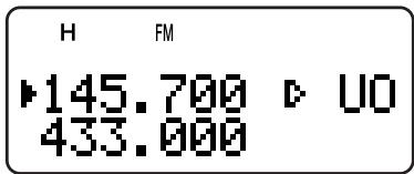
8 Press [MR] ([▶] or [MNU]) to store the end frequency in the memory channel.
Performing the Program Scan
1 Press [VFO].
2 Turn the Tuning control or press [▲]/[▼] to select a frequency within the frequency range of memory channel L0/U0 ~ L9/U9.
3 Press [VFO] (1 s) to start the Program Scan.
4 To stop the Program Scan, press [VFO] or [PTT].
Note:
If you press [MONI], Program Scan temporarily pauses. Release [MONI] to resume scanning.
If the Fine Tuning function is ON, the scanning does not stop at the busy channels.
The transceiver stops scanning in all modes when it detects a signal.
If more than 2 Program Scan channel pairs are stored and overlaps the frequency range among the pairs, the smaller Program Scan memory channel number has the priority.
To perform the Program Scan, the following conditions must be met. Otherwise, the Band scan starts {page 22}.
- The upper and lower limit frequencies are in the same frequency band.
- Ln < Un (where "n" is the Program Scan channel number).
MHz SCAN
MHz Scan allows you to scan an entire 1 MHz frequency range within the current VFO frequency.
1 Press [VFO].
2 Turn the Tuning control or press [▲]/[▼] to select a frequency in which to perform the MHz Scan. If you want to scan the entire 145 MHz frequency, select any frequency between 145.000 and 149.995 MHz (for example, select 145.650 MHz). Scan will operate between 145.000 MHz and 145.999 MHz.
3 Press [MHz] (1 s) to start the MHz Scan.
4 To stop the MHz Scan, press [MHz] or [PTT].
Note:
If the Fine Tuning function is ON, you cannot perform the MHz Scan.
If you press [MONI], MHz Scan temporarily pauses. Release [MONI] to resume scanning.
7 SCAN
MEMORY SCAN
Memory Scan monitors all memory channels in which you have stored frequencies (All-Channel Scan) or only a desired group of memory channels (Group Scan).
ALL-CHANNEL SCAN
The transceiver scans all of the memory channels in which you have stored frequencies.
1 Press [MR] (1 s).
- Scan starts from the last memory channel number and ascends up through the channel numbers (default). Turn the Tuning control or press [▲]/[▼] to change the scanning direction.
- To jump to a desired channel while scanning, quickly turn the Tuning control.
2 To stop the All-Channel Scan, press [MR] or [PTT].
Note:
You must have 2 or more memory channels that contain the data, excluding the special function memory channels.
If "CURRENT BAND" is selected for Menu No. 3 (MR METHOD), it scans only Memory channels that have the same frequency band data.
The transceiver stops scanning in all modes when it detects a signal.
GROUP SCAN
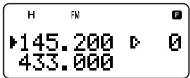
In order to easily manage all 400 memory channels, they are divided into 8 groups {page 18}. For the purpose of Group Scan, you can select a particular memory group to be scanned, depending on the situation. Using the Memory Group Link function {below}, you can scan all the linked memory groups.
1 Press [MR].
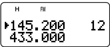
2 Turn the Tuning control or press [▲]/[▼] to select a memory channel in the group you want to scan. For example, if you want to scan the group 0 memory channels, recall memory channel 12 (group 0 contains memory channels 0 ~ 49).
![KENWOOD TH-F7E - Press [MR]. - 1](/content/2025/01/83302/images/abf68e6c386352bda72d51b0526ed4e23ee8680f51b13952cbfc7b88a38022a9.jpg)
3 Press [MHz] (1 s).
- The memory channels within the selected group are scanned.
- If the group is linked to other groups {below}, all the linked groups are also scanned.
4 To stop the Group Scan, press [MHz] or [PTT].
Note:
You must have 2 or more memory channels that contain the data, excluding the special function memory channels.
The Group Scan scans all available memory channels, regardless of Menu No. 3 (MR METHOD) selection {page 16}.
The transceiver stops scanning in all modes when it detects a signal.
Memory Group Link
Although the 400 memory channels are divided into 8 groups {page 18}, you may sometimes want to scan two or more groups. In this case, use the Memory Group Link function.
1 Press [MNU] to enter Menu mode.
2 Turn the Tuning control or press [▲]/[▼] to select Menu No. 2 (M.GRP LINK).
3 Press [▶] or [MNU].
- The memory group numbers appear.

4 Move the cursor using [] / [] , then turn the Tuning control or press [] / [] to select or deselect the group to be linked.
- Linked groups appear at the bottom of the display (in the example below, groups 0, 1, 3 and 5 are linked).

5 Press [▶] or [MNU] to store the setting. Otherwise, press [<] or [PTT] to cancel.
- You can press [MONI] to cancel the all links at once.
- You can also press [0] ~ [7] to select or deselect the group to be linked.
CALL SCAN
A Call channel can be stored for each amateur radio band, such as the 2m , 70cm , and 1.25m (TH-F6A only) bands {page 19}. You can monitor one of these Call channels and the current operating frequency alternatively.
1 Select the frequency (in VFO, Memory Recall, or Information Channel mode) you want to monitor.
- In VFO mode, press [A/B] to select the A or B-band. Then, turn the Tuning control or press [▲]/[▼] to select the desired frequency.
- In Memory Recall mode, turn the Tuning control or press [▲]/[▼] to select a memory channel you want to monitor.
- Press [INFO] to recall the last Information Channel you monitored.
2 Press [CALL] (1 s) to start the Call Scan.
3 The Call channel for the band and the selected VFO frequency, memory channel or Information Channel are monitored alternately.
4 To stop the Call Scan, press [PTT] or [CALL].
Note:
The transceiver stops scanning in all modes when it detects a signal.
You can perform the Call Scan even if the recalled memory channel or Information channel has been locked out (page 27).
If the Call channel is not available for the current operating frequency, an error beep sounds.
PRIORITY SCAN
You may sometimes want to check your favorite frequency activities while monitoring the A and B-bands. In this case, use the Priority Scan function. It checks the activities of Pr1 and Pr2 channels every 3 seconds, alternately, using the B-band receiver. If the transceiver detects a signal on Pr1 or Pr2, it recalls the frequency to the B-band receiver.
Note: If you do not operate any control or key for 3 seconds after the signal drops, the transceiver returns to the original frequency and resumes Priority Scan.
PROGRAMMING PRIORITY CHANNELS
1 Press [VFO].
2 Turn the Tuning control or press [A]/[V] to select your desired priority channel frequency.
3 Select the mode and selective call functions, if necessary.
4 Press [F].
- The memory channel number appears.
5 Turn the Tuning control or press [] / [] to select "Pr1".
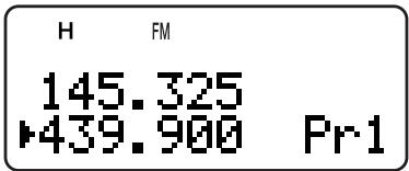
6 Press [MR] ([▶] or [MNU]) to store the data on the priority channel.
- If you want to store a second priority channel, repeat steps 1 ~ 6 and select "Pr2" in step 5.
Note: You can program any frequency available on the B-band as a priority channel.
USING PRIORITY SCAN
1 Press [F], [BAL].
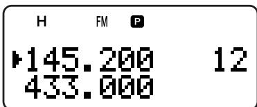
- “P” appears.
- The transceiver checks for a signal on the Pr1 and Pr2 channels every 3 seconds, alternately.
- When the transceiver detects a signal on the priority channel, "Pr1" or "Pr2" blinks and the B-band frequency changes to the priority channel.
- If you do not operate any control or key for 3 seconds after the signal drops, the transceiver returns to the original frequency and resumes Priority Scan.
2 To quit Priority Scan, press [F], [BAL] again.
7 SCAN
Note:
The signal being received on the B-band may become intermittent because the Priority Scan uses the B-band receiver to check the priority channel(s) activities.
When a signal is received on a Priority channel with a CTCSS or DCS code programmed, the Priority channel is recalled even if a different selective tone/ code is detected. However, the transceiver only unmutes if the signal has the same CTCSS tone or DCS code.
If the Tone Alert function {page 40} is ON for the B-band, it overrides the Priority Scan function. This means that you cannot monitor the received signal on the Priority Channels nor transmit on the Priority Channels.
Press and hold [MONI] to pause the Priority Scan when the transceiver is not displaying a priority channel. Release [MONI] to resume the Priority Scan.
If you clear the Priority Channels {page 16}, the Priority Scan stops.
If you press any key other than the following keys while "Pr1" or "Pr2" is blinking, the transceiver exits the Priority Scan: [LAMP], [MONI], [A/B], [SQL], [BAL], [F] (1 s), and [PTT].
If you perform the Visual Scan {below} while Priority Scan is activated, the Priority Scan temporarily pauses.
INFORMATION CHANNEL SCAN
Information Channel Scan is similar to Group Scan. However, it scans only Information channels.
1 Press [INFO].
- The last Information channel you used is recalled.
2 Press [INFO] (1 s) to start the Information Channel Scan.
3 To stop the Information Channel Scan, press [INFO].
- If necessary, press [A/B] to select the B-band and then press [VFO] or [MR] to select another frequency (channel) for the B-band.
Note: The transceiver stops scanning in all modes when it detects a signal.
VISUAL SCAN
While you are receiving, Visual Scan allows you to monitor frequencies near the current operating frequency. Visual Scan graphically displays the busy status of all frequencies in the selected range on the other band display area. You will see 6 different bar-graph levels, for each frequency (channel) point that represent relative S-meter levels.
The Visual Scan monitors ± 5 channels (frequencies) by centering on the current channel (frequency). In this way, a total of 11 channels' (frequencies') signal strength status are graphically displayed.
Note:
When you perform the Visual Scan on the A-band, the transceiver can output the audio. However, when you perform the Visual Scan on the B-band, it cannot output the audio. The S-meter does not reflect the signal strength, neither.
When the VOX function is activated, you cannot perform the Visual Scan.
When the Visual Scan is in progress, the other scan functions.
USING VISUAL SCAN (VFO)
1 Select your desired band for Visual Scan.
2 Press [VFO].
3 Turn the Tuning control or press [] / [] to select your desired center frequency.
- The transceiver scans the 5 upper frequencies and 5 lower frequencies using the current VFO frequency step {page 37}.
4 Press [F], [INFO] to start Visual Scan (VFO).
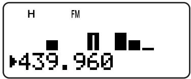
- The scanning frequency is displayed on the current operating band and the relative S-meter level of each frequency appears on the other band display.
- To pause Scan, press and hold [MONI]. While the Visual Scan is paused, the center frequency bar-graph blinks and you can monitor the frequency. Release [MONI] to resume the Visual Scan.
5 To change the current scanning frequency, Turn the Tuning control or press [▲]/[▼].
- The displayed frequency changes and the cursor moves.
6 To stop the Visual Scan, press [F], [INFO].
Note:
You can press [PTT] (or [CALL] if 1750 Hz is programmed) to transmit during the scan if the center frequency is within the transmission frequency range. The center bar-graph blinks while transmitting.
If the Fine Tuning function is ON, the Visual Scan cancels the Fine Tuning function and automatically adjusts the frequency to the next available frequency.
USING VISUAL SCAN (MEMORY CHANNEL)
1 Press [MR] to enter Memory Recall mode.
2 Turn the Tuning control or press [] / [] to select your desired center memory channel.
3 Press [F], [INFO] to start the Visual Scan.
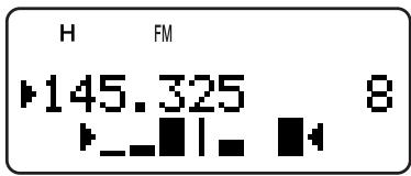
- The transceiver start scanning the 5 upper memory channels and 5 lower memory channels, by centering the selected memory channel.
- The current scanning memory channel number and frequency are displayed on the current operating band. On the other hand, the relative S-meter level of each frequency channel is displayed.
- To pause Scan, press and hold [MONI]. While the Visual Scan is paused, the center frequency bar-graph blinks and you can monitor the frequency. Release [MONI] to resume the Visual Scan.
4 To change the current scanning channel, turn the Tuning control or press [] / [] .
5 To stop the Visual Scan, press [F], [INFO].
Note:
You can press [PTT] (or [CALL] if 1750 Hz is programmed) to transmit during the scan if the center frequency is within the transmission frequency range. The center bar-graph blinks while transmitting.
If 11 or more memory channels are stored, "▶" and "↓" do not appear.
Even if the Fine Tuning ON status is stored in the memory channels, the Visual Scan (Memory Channel) starts.
MEMORY CHANNEL LOCKOUT
You can lock out memory channels that you prefer not to monitor during Memory Scan.
1 Press [MR] to enter Memory Recall mode.
2 Turn the Tuning control or press [] / [] to select the memory channel to be locked out.
3 Press [F], [MHz].
- “ ” appears at the top right of the memory channel number, indicating the channel is locked out.
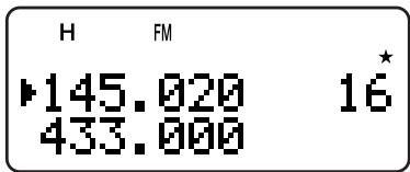
4 To unlock the memory channel, repeat steps 1 3
- “ ” disappears.
Note:
The Program Scan memories (L0/U0 ~ L9/U9) and Priority channels (Pr1 and Pr2) cannot be locked out.
Even if a memory channel is locked out, you can perform the Call Scan {page 25} between the Call channel and memory channel.
If the same memory channel is recalled to the A and B-band, you cannot lock out the channel.
SCAN RESUME METHOD
The transceiver stops scanning at the frequency (or memory channel) where a signal is detected. It then continues or stops scanning according to which resume mode you have selected.
Time-Operated mode (default)
The transceiver remains on a busy frequency (or memory channel) for approximately 5 seconds, then continues to scan, even if the signal is still present.
- Carrier-Operated mode
The transceiver remains on the busy frequency (or memory channel) until the signal drops out. There is a 2-second delay between signal dropout and scan resumption.
- Seek mode
The transceiver moves to a frequency or memory channel where a signal is present and stops.
To change the scan resume method:
1 Press [MNU].
2 Turn the Tuning control or press [▲]/[▼] to select Menu No. 1 (SCAN RESUME).

3 Press [▶] or [MNU].
4 Turn the Tuning control or press [▲]/[▼] to select "TIME" (Time-Operated mode), "CARRIER" (Carrier-Operated mode), or "SEEK" (Seek mode).
5 Press [▶] or [MNU] to store the setting. Otherwise, press [<] or [PTT] to cancel.
CTCSS and DCS
You may sometimes want to hear calls from only specific persons or groups. In this case, use the selective call function. This transceiver is equipped with CTCSS (Continuous Tone Coded Squelch System) and DCS (Digital Coded Squelch). These selective calls allow you to ignore (not hear) unwanted calls from other persons who are using the same frequency. The transceiver unmutes only when it receives the signal having the same CTCSS tone or DCS code.
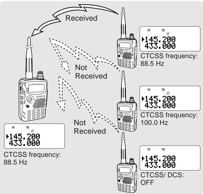
Note:
CTCSS and DCS do not cause your conversation to be private or scrambled. It only relieves you from listening to unwanted conversations.
CTCSS and DCS function in only FM mode.
CTCSS
A CTCSS tone is a sub-audible tone and is selectable from among the 42 tone frequencies listed in the table on the following page. The list includes 37 EIA standard tones and 5 non-standard tones. You can select one of the tones to use as a CTCSS tone.
USING CTCSS
Press [TONE] until "CT" appears.
Each time you press [TONE], the icon cycles as follows: "T" (TONE) "CT" (CTCSS) "DCS" (DCS) "T" (OFF) "T" (TONE).

When the CTCSS function is ON, you will hear calls only when the selected CTCSS tone is received. To answer the call, press and hold the PTT switch, then speak into the microphone.
Note:
You cannot use the CTCSS and Tone/ DCS functions simultaneously. Switching the CTCSS function ON after having activated the Tone/ DCS functions deactivates the Tone/ DCS functions.
If you select a high CTCSS frequency, receiving audio or noise that contains the same frequency portions may cause CTCSS to function incorrectly. To prevent noise from causing this problem, select an appropriate squelch level {page 6}.
While transmitting the 1750Hz tone by pressing [CALL] {page 13}, the transceiver does not transmit the CTCSS tone.
SELECTING A CTCSS FREQUENCY
1 While in CTCSS mode {above}, press [F], [TONE].
- The current CTCSS frequency appears.
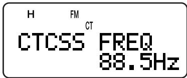
2 Turn the Tuning control or press [▲]/[▼] to select your desired CTCSS frequency.
- The selectable CTCSS frequencies are the same as those for the Tone frequency. Refer to the table on the following page for the available CTCSS frequencies.
3 Press [▶] or [MNU] to store the new setting. Otherwise, press [▶] or [PTT] to cancel.
CTCSS FREQ. ID SCAN
This function scans through all CTCSS frequencies to identify the incoming CTCSS frequency on the received signal. You may find this useful when you cannot recall the CTCSS frequency that the other persons in your group are using.
1 While the CTCSS function is ON, press [F], [TONE] (1 s) to start the CTCSS Freq. ID Scan function.

- To reverse the scan direction, turn the Tuning control or press [▲]/[▼].
- To quit the function, press [←] or [PTT].
- When a CTCSS frequency is identified, the identified frequency appears and blinks.
2 Press [▶] or [MNU] to program the identified frequency in place of the current CTCSS frequency. Otherwise, press [▶] if you do not want to program the identified frequency.
- Turn the Tuning control or press [▲]/[▼] while the identified frequency is blinking to resume scanning.
Available CTCSS frequencies
| No. | Freq. (Hz) | No. | Freq. (Hz) | No. | Freq. (Hz) | No. | Freq. (Hz) |
| 01 | 67.0 | 12 | 97.4 | 23 | 141.3 | 34 | 206.5 |
| 02 | 69.3 | 13 | 100.0 | 24 | 146.2 | 35 | 210.7 |
| 03 | 71.9 | 14 | 103.5 | 25 | 151.4 | 36 | 218.1 |
| 04 | 74.4 | 15 | 107.2 | 26 | 156.7 | 37 | 225.7 |
| 05 | 77.0 | 16 | 110.9 | 27 | 162.2 | 38 | 229.1 |
| 06 | 79.7 | 17 | 114.8 | 28 | 167.9 | 39 | 233.6 |
| 07 | 82.5 | 18 | 118.8 | 29 | 173.8 | 40 | 241.8 |
| 08 | 85.4 | 19 | 123.0 | 30 | 179.9 | 41 | 250.3 |
| 09 | 88.5 | 20 | 127.3 | 31 | 186.2 | 42 | 254.1 |
| 10 | 91.5 | 21 | 131.8 | 32 | 192.8 | ||
| 11 | 94.8 | 22 | 136.5 | 33 | 203.5 |
Note:
Received signals are monitored through the speaker while scanning is in progress.
CTCSS Freq. ID Scan does not scan the tone if a signal is not detected.
If the CTCSS function is activated for both the A and B-band, the scan speed may be slower.
DCS
DCS is similar to CTCSS. However, instead of using an analog audio tone, it uses a continuous subaudible digital waveform that represents a 3-digit octal number. You can select a DCS code from among the 104 DCS codes listed in the table below.
USING DCS
Press [TONE] until "DCS" appears.
Each time you press [TONE], the icon cycles as follows: "T" (TONE) "CT" (CTCSS) "DCS" (DCS) "T" (OFF) "T" (TONE).
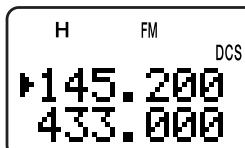
When the DCS function is ON, you will hear calls only when the selected DCS code is received. To answer the call, press and hold the PTT switch, then speak into the microphone.
Note: You cannot use the DCS function and CTCSS/ Tone functions simultaneously. Switching the DCS function ON after having activated the CTCSS/ Tone functions deactivate the CTCSS/ Tone functions.
SELECTING A DCS CODE
1 While in DCS mode {above}, press [F], [TONE].
- The current DCS code appears.
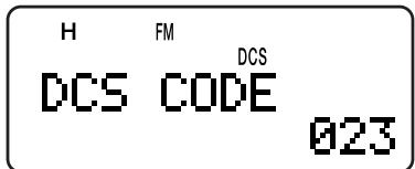
2 Turn the Tuning control or press [▲]/[▼] to select your desired DCS code.
- The available DCS codes are shown in the following table.
| 023 | 065 | 132 | 205 | 255 | 331 | 413 | 465 | 612 | 731 |
| 025 | 071 | 134 | 212 | 261 | 332 | 423 | 466 | 624 | 732 |
| 026 | 072 | 143 | 223 | 263 | 343 | 431 | 503 | 627 | 734 |
| 031 | 073 | 145 | 225 | 265 | 346 | 432 | 506 | 631 | 743 |
| 032 | 074 | 152 | 226 | 266 | 351 | 445 | 516 | 632 | 754 |
| 036 | 114 | 155 | 243 | 271 | 356 | 446 | 523 | 654 | |
| 043 | 115 | 156 | 244 | 274 | 364 | 452 | 526 | 662 | |
| 047 | 116 | 162 | 245 | 306 | 365 | 454 | 532 | 664 | |
| 051 | 122 | 165 | 246 | 311 | 371 | 455 | 546 | 703 | |
| 053 | 125 | 172 | 251 | 315 | 411 | 462 | 565 | 712 | |
| 054 | 131 | 174 | 252 | 325 | 412 | 464 | 606 | 723 |
3 Press [▶] or [MNU] to store the new setting. Otherwise, press [<] or [PTT] to cancel.
DCS CODE ID SCAN
This function scans through all DCS codes to identify the incoming DCS code on the received signal. You may find this useful when you cannot recall the DCS code that the other persons in your group are using.
1 While in DCS mode, press [F], [TONE] (1 s) to start the DCS Code ID Scan function.
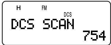
- To reverse the scan direction, turn the Tuning control or press [A]/[V].
To quit the function, press [<] or [PTT]. - When a DCS code is identified, the identified code appears and blinks.
2 Press [▶] or [MNU] to program the identified frequency in place of the current DCS code. Otherwise, press [▶] if you do not want to program the identified code.
- Turn the Tuning control or press [▲]/[▼] while the identified DCS code is blinking to resume scanning.
Note:
Received signals are monitored through the speaker while scanning is in progress.
DCS Code ID Scan does not scan the code if a signal is not detected.
If the DCS function is activated for both the A and B-band, the scan speed may be slower.
The keys on the keypad also function as DTMF keys; the 12 keys found on a touch-tone phone plus 4 additional keys (A, B, C, D). This transceiver also provides 10 dedicated DTMF memory channels. You can store a DTMF number (16 digits max.) with a memory name (8 digits max.) in each of the channels to recall later for speed dialing.
Many repeaters in the U.S.A. and Canada offer a service called Autopatch. You can access the public telephone network via such a repeater by sending DTMF tones. For further information, consult your local repeater reference.
MANUAL DIALING
Manual Dialing requires only two steps to send DTMF tones.
1 Press and hold the PTT switch to transmit.
2 While transmitting, press the keys in sequence on the keypad to send DTMF tones.
- The corresponding DTMF tones are transmitted and monitored through the speaker.
While pressing keys on the keypad, the transceiver remains in the TX mode. You do not have to press [PTT] at the same time.
| Freq. (Hz) | 1209 | 1336 | 1477 | 1633 |
| 697 | 1 | 2 | 3 | A |
| 770 | 4 | 5 | 6 | B |
| 852 | 7 | 8 | 9 | C |
| 941 | * | 0 | # | D |
DTMF TX HOLD
This function causes the transceiver to remain in transmit mode for 2 seconds after you release each key. So, you can release the PTT switch while sending the DTMF tones.
1 Press [MNU] to enter Menu mode.
2 Turn the Tuning control or press [▲]/[▼] to select Menu No. 12 (DTMF HOLD).
3 Press [▶] or [MNU].
4 Turn the Tuning control or press [A]/[V] to select "ON".

5 Press [▶] or [MNU] to store the setting. Otherwise, press [<] or [PTT] to cancel.
AUTOMATIC DIALER
If you use the 10 dedicated memory channels to store DTMF numbers, you need not remember a long string of digits.
STORING A DTMF NUMBER IN MEMORY
Note: Audible DTMF tones from other transceivers near you (or from your own speaker) may be picked up by your microphone. If so, you may fail to correctly program a DTMF number.
1 Press [MNU] to enter Menu mode.
2 Turn the Tuning control or press [▲]/ [▼] to select Menu No. 10 (DTMF STORE).
3 Press [▶] or [MNU].

4 Turn the Tuning control or press [▲]/[▼] to select your desired DTMF memory channel number from 0 to 9.
5 Press [▶] or [MNU].
- The display for entering a memory name appears; the first digit blinks.
- To skip naming the channel, press [▶] or [MNU] again; jump to step 9.

6 Turn the Tuning control or press [▲]/ [▼] to select a character. Refer to "NAMING A MEMORY CHANNEL" {page 17} for the available characters and the input method.
- You can enter alphanumeric characters plus special ASCII characters.
- Press [MONI] to delete the character at the cursor.
- You can also use the numeric keypad to enter a character (special ASCII characters are not available). For example, each press of [2] switches entry as a, b, c, 2, A, B, C and then back to a.
While pressing and holding [LAMP], turn the Tuning control to jump to the first character of each ASCII character group {page 17}.
7 Press [▶] to move the cursor to the next digit.
8 Repeat steps 6 and 7 to enter up to 8 digits.

9 DTMF FUNCTIONS
- Pressing [▶] after selecting the 8th digit completes the programming.
To complete programming a name with less than 8 digits, press [MNU] or [ ] twice.
Each press of [] causes the cursor to move backward.
9 Press the keys in sequence on the keypad to enter a DTMF number with up to 16 digits.

- You can also turn the Tuning control or press [▲]/[▼] to select the required DTMF number for each digit. Select a space if you want to put a pause.
- Press [MONI] to delete a number at the cursor.
10 Press [▶] or [MNU] to complete the programming.

You can confirm the stored DTMF number by using steps 1 to 4.
TRANSMITTING A STORED DTMF NUMBER
1 While pressing and holding [PTT], press [MNU].
2 Release only [MNU], then turn the Tuning control or press [] / [] to select the desired DTMF memory channel.
3 While still holding [PTT], press or [MNU] to transmit the DTMF tones.

- The number stored in the channel scrolls across the display accompanied by DTMF tones from the speaker.
After transmission, the frequency display is restored.
If you do not need to confirm the memory channel contents, press [0] to [9] instead of turning the Tuning control or pressing []/[] in step 2 to select a channel number. The stored DTMF number will be immediately transmitted. You need not press [] or [MNU] in step 3.
Note: If you select an empty DTMF memory channel and press [MNU] or [▶], an error beep sounds and the frequency display is restored.
ADJUSTING THE DTMF TONE TRANSMISSION SPEED
This transceiver allows you to configure the DTMF number transmission speed between Fast (default) and Slow. If a repeater cannot respond to the fast speed, adjust this parameter.
1 Press [MNU] to enter Menu mode.
2 Turn the Tuning control or press [▲]/[▼] to select Menu No. 11 (DTMF SPD).
3 Press [▶] or [MNU].
4 Turn the Tuning control or press [] / [] to select "FAST" (default) or "SLOW".
- The tone duration of FAST is 50~ms and SLOW is 100~ms .
5 Press [▶] or [MNU] to store the setting. Otherwise, press [←] or [PTT] to cancel.
ADJUSTING THE PAUSE DURATION
You can also change the pause duration (a space digit) stored in memory channels; the default is 500 ms.
1 Press [MNU] to enter Menu mode.
2 Turn the Tuning control or press [▲]/[▼] to select Menu No. 13 (DTMF PAUSE).
3 Press [▶] or [MNU].
4 Turn the Tuning control or press [▲]/[▼] to select 100/250/500 (default)/750/1000/1500/2000 ms.
5 Press [▶] or [MNU] to store the setting. Otherwise, press [←] or [PTT] to cancel.
DTMF LOCK
Assuming you have a transceiver with the optional speaker microphone installed and you are carrying it in the holder or bag, you sometimes may want to disable the keypad DTMF transmission to avoid accidental DTMF transmission. In this case, turn the DTMF Lock function ON.
1 Press [MNU] to enter Menu mode.
2 Turn the Tuning control or press [▲]/[▼] to select Menu No. 14 (DTMF LOCK).
3 Press [▶] or [MNU].
4 Turn the Tuning control or press [▲]/[▼] to select "ON".
5 Press [▶] or [MNU] to store the setting. Otherwise, press [←] or [PTT] to cancel.
When this function is activated, you cannot transmit DTMF tones using the DTMF keypad (including [MNU]) during transmission.
ABOUT THE B-BAND
Usually you can communicate with other amateur radio stations using A-band frequencies for receiving and transmitting. This transceiver also features another receiver in addition to the A-band transceiver. The frequency for the B-band appears on the bottom part of the display. Although the A-band transceiver covers only the 2m/1.25m (TH-F6A only)/70 cm amateur radio bands in FM mode, the B-band receiver can receive signals from 100 kHz to 470 MHz in SSB, CW, FM, or AM mode, and from 470 MHz to 1.3 GHz in FM or AM mode.
In this way, you can monitor 2 different frequencies at the same time. For example, you can listen to a local FM broadcasting station on the B-band while you are monitoring your club channel on the A-band.
If one of the A-band amateur radio bands is selected for the B-band receiver in FM mode, you can also transmit on the B-band frequency.
B-BAND FREQUENCY
Since the B-band frequency coverage is so wide, the default frequency band, mode, and frequency step size are preprogrammed as shown below.
1 Press [A/B] to select B-band.
- The “ ” icon moves, indicating which band is currently selected for operation.
2 Press [BAND] until the desired frequency band appears.
Each time you press [BAND], the frequency band cycles from the last band you selected to the upper band frequency. When it reaches the 23 cm band, it returns to the AM band.
- You can also press []/[] to select your desired band in VFO mode {page 7}.

3 Turn the Tuning control or press [A]/[V] to tune to a desired frequency.
Note: You can also select one of the amateur radio bands to transmit on the B-band frequency. However, you must be operating in FM mode to transmit.
B-band Frequency Coverage (TH-F6A)
| Band | Frequency | Step | Mode |
| AM band | 100 kHz ~ 520 kHz | 5 kHz | AM |
| 520 kHz ~ 1.8 MHz | 10 kHz | AM | |
| HF | 1.8 MHz ~ 3.5 MHz | 100 Hz(FINE ON) | AM |
| 3.5 MHz ~ 4.0 MHz | LSB | ||
| 4.0 MHz ~ 7.0 MHz | AM | ||
| 7.0 MHz ~ 7.3 MHz | LSB | ||
| 7.3 MHz ~ 10.1 MHz | AM | ||
| 10.1 MHz ~ 10.15 MHz | CW | ||
| 10.15 MHz ~ 14.0 MHz | AM | ||
| 14.0 MHz ~ 14.35 MHz | USB | ||
| 14.35 MHz ~ 18.068 MHz | AM | ||
| 18.068 MHz ~ 18.168 MHz | USB | ||
| 18.168 MHz ~ 21.0 MHz | AM | ||
| 21.0 MHz ~ 21.45 MHz | USB | ||
| 21.45 MHz ~ 24.89 MHz | AM | ||
| 24.89 MHz ~ 24.99 MHz | USB | ||
| 24.99 MHz ~ 28.0 MHz | AM | ||
| 28.0 MHz ~ 29.7 MHz | USB | ||
| 6 m | 29.7 MHz ~ 50.0 MHz | 25 kHz | FM |
| 50.0 MHz ~ 54.0 MHz | 10 kHz | ||
| FM band | 54.0 MHz ~ 108.0 MHz | 100 kHz | FMW |
| Air band | 108.0 MHz ~ 137.0 MHz | 12.5 kHz | AM |
| 2 m | 137.0 MHz ~ 144.0 MHz | 5 kHz | FM |
| 144.0 MHz ~ 148.0 MHz | 5 kHz | ||
| 148.0 MHz ~ 174.0 MHz | 5 kHz | ||
| VHF TV | 174.0 MHz ~ 216.0 MHz | 50 kHz | FMW |
| 1.25 m | 216.0 MHz ~ 220.0 MHz | 12.5 kHz | FM |
| 220.0 MHz ~ 225.0 MHz | 20 kHz | ||
| 225.0 MHz ~ 400.0 MHz | 12.5 kHz | ||
| 70 cm | 400.0 MHz ~ 420.0 MHz | 12.5 kHz | |
| 420.0 MHz ~ 450.0 MHz | 25 kHz | ||
| 450.0 MHz ~ 470.0 MHz | 12.5 kHz | ||
| UHF TV | 470.0 MHz ~ 806.0 MHz | 50 kHz | FMW |
| 23 cm | 806.0 MHz ~ 1240.0 MHz | 12.5 kHz | FM |
| 1240.0 MHz ~ 1300.0 MHz | 25 kHz |
Note:
By default, the Fine Tuning function is activated automatically for 1.8MHz 29.7MHz
Cellular band is blocked due to government regulations.
10 UTILIZING THE B-BAND
B-band Frequency Coverage (TH-F7E)
| Band | Frequency | Step | Mode |
| AM band | 100 kHz ~ 520 kHz | 5 kHz | AM |
| 520 kHz ~ 1.71 MHz | 10 kHz | AM | |
| HF | 1.71 MHz ~ 3.5 MHz | 100 Hz(FINE ON) | AM |
| 3.5 MHz ~ 4.0 MHz | LSB | ||
| 4.0 MHz ~ 7.0 MHz | AM | ||
| 7.0 MHz ~ 7.3 MHz | LSB | ||
| 7.3 MHz ~ 10.1 MHz | AM | ||
| 10.1 MHz ~ 10.15 MHz | CW | ||
| 10.15 MHz ~ 14.0 MHz | AM | ||
| 14.0 MHz ~ 14.35 MHz | USB | ||
| 14.35 MHz ~ 18.068 MHz | AM | ||
| 18.068 MHz ~ 18.168 MHz | USB | ||
| 18.168 MHz ~ 21.0 MHz | AM | ||
| 21.0 MHz ~ 21.45 MHz | USB | ||
| 21.45 MHz ~ 24.89 MHz | AM | ||
| 24.89 MHz ~ 24.99 MHz | USB | ||
| 24.99 MHz ~ 28.0 MHz | AM | ||
| 28.0 MHz ~ 29.7 MHz | USB | ||
| 6 m | 29.7 MHz ~ 46.0 MHz | 5 kHz | FM |
| 46.0 MHz ~ 50.0 MHz | 50 kHz | FMW | |
| 50.0 MHz ~ 52.0 MHz | 10 kHz | FM | |
| 52.0 MHz ~ 68.0 MHz | 50 kHz | FMW | |
| 68.0 MHz ~ 87.5 MHz | 5 kHz | FM | |
| FM band | 87.5 MHz ~ 108.0 MHz | 50 kHz | FMW |
| Air band | 108.0 MHz ~ 137.0 MHz | 25 kHz | AM |
| 2 m | 137.0 MHz ~ 144.0 MHz | 5 kHz | FM |
| 144.0 MHz ~ 146.0 MHz | 12.5 kHz | ||
| 146.0 MHz ~ 174.0 MHz | 5 kHz | ||
| VHF TV | 174.0 MHz ~ 230.0 MHz | 50 kHz | FMW |
| 1.25 m | 230.0 MHz ~ 400.0 MHz | 12.5 kHz | FM |
| 70 cm | 400.0 MHz ~ 430.0 MHz | 12.5 kHz | FM |
| 430.0 MHz ~ 440.0 MHz | 25 kHz | ||
| 440.0 MHz ~ 470.0 MHz | 12.5 kHz | ||
| UHF TV | 470.0 MHz ~ 862.0 MHz | 50 kHz | FMW |
| 23 cm | 862.0 MHz ~ 1240.0 MHz | 12.5 kHz | FM |
| 1240.0 MHz ~ 1300.0 MHz | 25 kHz |
Note: By default, the Fine Tuning function is activated automatically for 1.71 MHz ~ 29.7 MHz.
SELECTING A MODE FOR THE B-BAND
When using the B-band receiver, the following receiving mode is available.
| Receiving Mode | Available Frequency Ranges |
| LSB/ USB | 100 kHz ≤ f < 470 MHz |
| CW | 100 kHz ≤ f < 470 MHz |
| AM | 100 kHz ≤ f < 1.3 GHz |
| FM | 100 kHz ≤ f < 1.3 GHz |
| WFM | 29.7 MHz ≤ f < 1.3 GHz |
LSB/USB/CW/AM/FM/WFM
To select the receiving mode for the B-band:
1 Press [VFO].
2 Press [A/B] to select the B-band.
3 Press [BAND], then turn the Tuning control or press []/[] to select the desired frequency.
4 Press [F], [BAND] repeatedly until you select the desired receiving mode. The mode icon cycles from FM WFM AM LSB USB CW, and then goes back to FM.
Note:
"FMN" appears in place of "FM" when you select "ON" for the Menu No. 29 (FM NARROW) {page 39}.
Select "WFM" when you receive the audio signal of the broadcasting stations, such as FM or TV stations.
If the Fine Tuning function is ON {page 35}, you cannot select FM mode (FM/NFM/WFM). To select FM mode, turn the Fine Tuning function OFF.
BAR ANTENNA
Although the supplied wide-band helical antenna is used for receiving B-band frequencies, due to the size and length limitation, it may not be suitable for low HF band (below 10.1 MHz) reception. The transceiver features a built-in bar antenna for the reception frequency below 10.1 MHz. The transceiver automatically switches to the bar antenna when you select a frequency below 10.1 MHz for the B-band. However, you can connect an external antenna to the antenna connector instead.
To disable the built-in bar antenna below 10.1 MHz:
1 Press [MNU].
2 Turn the Tuning control or press [▲]/[▼] to select Menu No. 26 (BAR ANT).
3 Press [▶] or [MNU].
4 Turn the Tuning control or press [▲]/[▼] to select "DISABLED".
5 Press [▶] or [MNU] to store the setting.
Note: The bar antenna is embedded in the base of the transceiver, horizontally. The antenna has the same characteristics as a dipole antenna. If the target station's signal is weak, rotate the transceiver to find the best receiving position.
FINE TUNING
When you operate the B-band in LSB, USB, CW, or AM mode, you can turn the Fine Tuning function ON. You can further configure the Fine Tuning frequency step size from 33Hz , 100Hz (default), 500Hz , or 1000Hz .
ACTIVATING FINE TUNING
To activate the Fine Tuning function:
1 Press [VFO].
2 Select a frequency (below 470 MHz) on the B-band.
- The operating mode must be LSB, USB, CW or AM.
3 Press [FINE].
100 Hz digit appears.

4 Turn the Tuning control or press [A]/[V] to tune to a station.
Note:
The Fine Tuning function works only when you operate the frequency below 470 MHz.
You cannot activate the Fine Tuning function on the A-band.
The Fine Tuning function does not work in FM mode (FM/ WFM/NFM).
While in Fine Tuning mode, you cannot change the frequency step size {page 37}, MHz mode {page 7}, and MHz Scan {page 23}.
When you perform the Visual Scan {page 26} or direct frequency entry (excluding the same frequency band) {page 7}, the transceiver exits Fine Tuning mode.
Simply turning the Fine Tuning function OFF will not change the current frequency or display. However, when you change the frequency, the transceiver will use the currently selected frequency step size {page 37} and adjust the frequency accordingly, removing the transceiver from a finely tuned frequency.
Selecting a Fine Tuning Frequency Step
You can select Fine Tuning frequency step from 33 Hz, 100 Hz (default), 500 Hz, or 1000 Hz.
To select the Fine Tuning frequency step size:
1 Select a frequency on the B-band.
2 While the Fine Tuning mode is activated, press [F], [FINE].
- The current frequency step size appears.
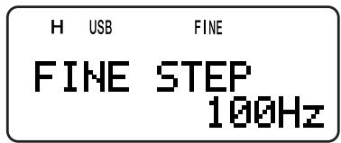
3 Turn the Tuning control or press [▲]/[▼] to select your desired frequency step from 33 Hz, 100 Hz (default), 500 Hz, or 1000 Hz.
4 Press [▶] or [MNU] to store the new setting.
Note: The Fine Tuning frequency step size reflects all available frequencies below 470 MHz for the B-band.
APO (Auto Power OFF)
The transceiver switches OFF automatically if no keys or controls are pressed or adjusted, and no signal is received for 30 minutes (default). 1 minute before the transceiver switches OFF, warning beeps sound for a few seconds and "APO" blinks. Then, the transceiver turns OFF automatically. You can select the APO time from OFF (disable), 30 (default), and 60 minutes.
1 Press [MNU].
2 Turn the Tuning control or press [▲]/[▼] to select Menu No. 18 (APO).
3 Press [▶] or [MNU].
4 Turn the Tuning control or press [] / [] to select the APO time from OFF, 30, or 60 minutes.
5 Press [▶] or [MNU] to store the setting. Otherwise, press [←] or [PTT] to cancel.
Note:
The APO function does not work if the transceiver is scanning.
When Tone Alert is ON, APO does not turn the power OFF.
The APO timer starts counting down the time when no key presses, no control adjustments, and no command (SP/MIC jack) sequences are detected.
The APO warning beep sounds even if Menu No. 19 (KEY BEEP) {page 37} is selected "OFF".
ATTENUATOR
The attenuator function is useful when extremely strong signals exist nearby your receiving frequency. When these type of signals are present, the receiver gain control may be erroneously controlled and overloaded by the strong signals, rather than by the target receiving signal. If this happens, the target receiving signal can be masked and buried by the strong signals. In this case, turn the Attenuator (approx. 20 dB) function ON. However, as a side effect, the target signal is also attenuated. You may have to adjust the VOL control to increase the audio output level when it is ON.
1 Press [F], [MONI].
![KENWOOD TH-F7E - Press [F], [MONI]. - 1](/content/2025/01/83302/images/96970cfcc0ed812840ce93045e69c752876728301c324c5b7c6ecb0975dbe046.jpg)
- "ATT ON" appears for 2 seconds on the display and the mode indicator starts blinking.
2 To turn the attenuator function OFF, press [F], [MONI] again.
- The mode indicator quits blinking.
Note:
When the attenuator function is ON, both A and B-band, are attenuated. You cannot set the attenuator function independently for each band.
"ATT ON" does not appear while scanning.
BATTERY LIFE
Before you operate the transceiver outside using a battery pack, it is important to know how long you can operate the transceiver. The following operating time is measured under the condition of TX: 6 seconds, RX: 6 seconds, and Stand-by: 48 seconds cycles. We recommend you carrying extra battery packs, in case the battery pack is discharged.
| Battery Type | Output Power | Operating Time/ Hours (Approx.) | ||
| 2 m | 1.25 m | 70 cm | ||
| PB-42L (7.4 V) | H | 6.5 | 6.0 | 6.0 |
| L | 12.0 | 11.5 | 11.5 | |
| EL | 16.0 | 15.5 | 14.5 | |
| BT-13 (6.0 V) | H | 5.0 | ||
| L | 6.0 | |||
| EL | 8.0 | |||
BATTERY REMAINING
You can confirm the remaining battery capacity using this function. Confirm the battery type {below} prior to use this function. To check the remaining capacity:
1 Press [F], [LOW].
![KENWOOD TH-F7E - Press [F], [LOW]. - 1](/content/2025/01/83302/images/b9edabd8123fc37b624dad9711d152ee6e14ddf64de162362efe53af08a253a0.jpg)
- The battery remaining indicator appears.
: High battery power
Medium battery power
Low battery power
1: Needs recharging or replace the batteries
2 Press [▶] or [MNU] to exit the Battery remaining display mode.
Note: If you press [F], [LOW] while charging, "CHARGE" or "STANDBY" appears {page 2}.
BATTERY TYPE
Before estimating the remaining battery capacity, set the battery type in Menu No. 30 (BATTERY) to the same type of battery that your are using (either Lithium or alkaline).
1 Press [MNU].
2 Turn the Tuning control or press [▲]/[▼] to select Menu No. 30 (BATTERY).
3 Press [▶] or [MNU].
4 Turn the Tuning control or press [▲]/ [▼] to select the battery type from "LITHIUM" and "ALKALINE".
5 Press [▶] or [MNU] to store the setting. Otherwise, press [<] or [PTT] to cancel.
Note: Use the PB-42L (Lithium battery pack) within the temperature range of -10^ 50^ 14^ 122^
BATTERYSAVER
Battery Saver extends the operating time of the transceiver. It automatically activates when the squelch is closed and no key is pressed for more than 10 seconds. To reduce the battery consumption, it shuts the receiver circuit OFF for the programmed time then momentarily turn it back ON to detect a signal. To program the receiver shut-off period for the battery saver:
1 Press [MNU].
2 Turn the Tuning control or press [▲]/[▼] to select Menu No. 17 (BAT Saver).
3 Press [▶] or [MNU].
4 Turn the Tuning control or press [▲]/[▼] to select the receiver shut-off period from OFF, 0.2, 0.4, 0.6, 0.8, 1.0 (default), 2.0, 3.0, 4.0, and 5.0 seconds.
5 Press [▶] or [MNU] to store the setting. Otherwise, press [<] or [PTT] to cancel.
Note:
The longer the period, the more you can save the battery consumption. However, there is a greater chance of missing a signal.
When the DC IN jack is used, the Battery Saver function is automatically turned OFF.
The Battery Saver function does not work while scanning.
The Battery Saver function does not work in USB/ LSB/ CW.
BEAT SHIFT
Since the transceiver uses a microprocessor to control various functions of the transceiver, the CPU clock oscillator's harmonics or image may appear on some spots of the receiving frequencies. In this case, turn the Beat Shift function ON.
1 Press [MNU].
2 Turn the Tuning control or press [▲]/[▼] to select Menu No. 25 (BEAT SHIFT).
3 Press [▶] or [MNU].
4 Turn the Tuning control or press [] / [] to select "ON".
5 Press [▶] or [MNU] to store the setting. Otherwise, press [←] or [PTT] to cancel.
BEEP FUNCTION
The Beep function provides you confirmation of entry, error status, and malfunctions of the transceiver. We recommend you leave it ON in order to detect erroneous operations and malfunctions.
However, to turn the beep function OFF:
1 Press [MNU].
2 Turn the Tuning control or press [▲]/[▼] to select Menu No. 19 (KEY BEEP).
3 Press [▶] or [MNU].
4 Turn the Tuning control or press [▲]/[▼] to select "OFF".
5 Press [▶] or [MNU] to store the setting. Otherwise, press [<] or [PTT] to cancel.
The transceiver generates the following warning beeps even if the beep function is turned OFF.
APO warning beeps {page 36}
DC voltage error {page 2}
PLL circuit malfunctions
Time-Out timer warning beep{page 40}
Note: The beep output level is linked to the VOL control position.
DISPLAY CONTRAST
You can adjust the LCD contrast level from 1 (weakest) to 16 (strongest) by accessing Menu No. 16 (CONTRAST). The default level is 8.
1 Press [MNU].
2 Turn the Tuning control or press [▲]/[▼] to select Menu No. 16 (CONTRAST).
3 Press [▶] or [MNU].
4 Turn the Tuning control or press [▲]/[▼] to adjust the LCD contrast.

- The relative contrast level appears on the bar-graph.
5 Press [▶] or [MNU] to store the setting. Otherwise, press [<] or [PTT] to cancel.
Note: If you continuously transmit or leave the transceiver sitting in a hot atmosphere, the background of the LCD display may turn grey and the contrast will become reduced. In this case, turn the transceiver OFF or let the transceiver cool down for a while. After the transceiver cools down, the LCD display returns normal.
FREQUENCY STEP SIZE
Choosing the correct frequency step size is essential in order to select your exact receive frequency using the Tuning control or pressing [▲]/[▼]. You can select your desired frequency step size from:
5 kHz, 6.25 kHz, 8.33 kHz (Air band only),
9 kHz (AM band only), 10 kHz, 12.5 kHz, 15 kHz,
20 kHz, 25 kHz, 30 kHz, 50 kHz, 100 kHz.
Note: 5 KHz, 6.25 kHz, and 15 kHz step size cannot be used on the frequency above 470 MHz.
11 OPERATOR CONVENIENCES
The default step size for the amateur radio bands are as follows.
| Band | Amateur Radio Band | TH-F6A | TH-F7E |
| A-band | 2 m | 5 kHz | 12.5 kHz |
| 1.25 m | 20 kHz | — | |
| 70 cm | 25 kHz | 25 kHz | |
| B-band | 2 m | 5 kHz | 12.5 kHz |
| 1.25 m | 20 kHz | 12.5 kHz | |
| 70 cm | 25 kHz | 25 kHz | |
| 23 cm | 25 kHz | 25 kHz |
For the B-band, refer to pages 33 and 34 for the default frequency step size in the various frequency bands. The transceiver stores the frequency step size parameter for each band independently. You can also further fine tune the frequency in LSB, USB, AM, and CW modes on the B-band {page 34}.
To change the frequency step size:
1 Press [F], [FINE].
- The current frequency step size appears.
2 Turn the Tuning control or press [A]/[V] to select your desired frequency step size.
3 Press [▶] or [MNU] to store the setting. Otherwise, press [←] or [PTT] to cancel.
Note: If you change to a frequency step size that does not match the current operating frequency, the transceiver automatically adjusts the frequency to match the new frequency step size.
LAMP
To illuminate the transceiver:
Press [LAMP].
- Approximately 5 seconds after releasing [LAMP], the light goes OFF if no other key is pressed.
- Pressing any key, including [PTT] other than [LAMP] while the display is lit, restarts the 5-second timer.
- Pressing [LAMP] turns the light OFF immediately.
To keep the light ON continuously:
Press [F], [LAMP].
- The light remains ON until you press [F], [LAMP] again.
LOCK FUNCTION
The lock function disables most of the keys to prevent you from accidentally activating a function.
1 Press [F] (1 s).
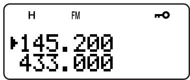
-
"n-o" appears when this function is ON.
-
The following keys cannot be locked:
[LAMP], [MONI], [SQL], [PTT], [F] (1 s), [∅] (POWER) and [F] then [LAMP].
2 Press [F] (1 s) to unlock the keys.
Note:
The Tuning control is also locked. To unlock the Tuning control while the Lock function is ON, access Menu No. 7 (TUNE ENABLE) and select "ON".
You cannot perform the Microprocessor reset {page 50} while the Lock function is ON.
Microphone PF keys {below} work even if the Lock function is ON.
TUNE ENABLE
Even if the Lock function is ON, you sometimes may want to turn the Tuning control to change the frequency. In this case, turn the Tune Enable function ON.
1 Press [MNU].
2 Turn the Tuning control or press [▲]/[▼] to select Menu No. 7 (TUNE ENABLE).
3 Press [▶] or [MNU].
4 Turn the Tuning control or press [▲]/[▼] to select "ON".
5 Press [▶] or [MNU] to store the setting. Otherwise, press [←] or [PTT] to cancel.
MICROPHONE PF KEYS (OPTIONAL)
If you have an optional SMC-33 or SMC-34 speaker microphone, you can access many transceiver settings without using transceiver keys or controls. The 1, 2, and 3 keys located on the top of the microphone are programmable with the transceiver key (or key combination) functions. The default assignments are as follows.
Mic [1]: A/B
Mic [2]: VFO/ MR
Mic [3]:CALL (TH-F6A)/1750 Hz (TH-F7E)
Note:
Turn the transceiver OFF before connecting the optional speaker microphone.
If the LOCK switch on the rear of the microphone is ON, you must move the switch to the OFF position to program the keys.
1 Press one of the following key combinations to reprogram the keys on the speaker microphone.
Press Mic [1]+[ 念 ] (POWER) to re-program Mic [1]
- Press Mic [2]+[ 念 ] (POWER) to re-program Mic [2]
Press Mic [3] + [O] (POWER) to re-program Mic [3]
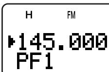
2 Press a key or key combination you want to assign to the function key.
| [KEY] | |
| LAMP | REV |
| MONI | MN<-f |
| LOW | MHz |
| BAND | FINE |
| A/B | VFO |
| INFO | MR |
| SQL | CALL3 |
| BAL | 1750 Hz3 |
| TONE | ▲/▼1 |
| MNU | ▲/▲ |
| [F] + [KEY] | |
| LAMP2 | MN.IN |
| BATT | L.OUT |
| MODE | STEP |
| DUAL | ♀ |
| VISUAL | M>V |
| VOX | M.IN |
| PRI | C.IN |
| T.SEL | ATT |
| SHIFT | |
1 Tuning control (Up or Down) can be also programmed.
2 The light stays ON until you press the key again {above}.
3 Both keys cannot be assigned to the PF keys at the same time (TH-F7E only).
You can also press [PTT] to assign a function key to alternate VFO and Memory Recall mode.
MONITOR
When you are receiving while the squelch function is ON, weak signals may become intermittent.
Or, if the CTCSS or DCS function is ON, you may want to disable the squelch function temporarily to monitor the current channel activities.
In these cases, use the Monitor function to disable the squelch function temporarily.
To activate the Monitor function:
1 Press and hold [MONI].
- The speaker is unmuted and you can monitor the signals.
2 Release [MONI] key to return to normal operation.
By default, if you select FM mode, the transceiver operates in normal FM deviation (± 5kHz) mode for both transmission and reception. You can also operate the transceiver in narrow band FM deviation (± 2.5kHz) mode on 2m , 1.25m (TH-F6A only), and 70cm bands for both A and B-bands. To operate the transceiver in narrow band FM:
1 Press [MNU].
2 Turn the Tuning control or press [▲]/[▼] to select Menu No. 29 (FM NARROW).
3 Press [▶] or [MNU].
4 Turn the Tuning control or press [] / [] to select "ON".
5 Press [▶] or [MNU] to store the setting. Otherwise, press [<] or [PTT] to cancel.
When narrow band FM operation is ON, "FMN" appears instead of "FM".
Note:
When you select "9600" bps for the Menu No. 28 (PACKET), the operating mode temporarily returns to a normal FM mode.
You can store the narrow band FM operation status to each amateur radio band.
POWER-ONMESSAGE
You can change the greeting message (a maximum of 8 characters) when the transceiver is turned ON.
1 Press [MNU].
2 Turn the Tuning control or press [▲]/ [▼] to select Menu No. 15 (PWR-ON MSG).
3 Press [▶] or [MNU].
- The current message and entry cursor appear.

4 Turn the Tuning control or press [A]/[V] to select the first character.
- You can enter alphanumeric characters plus special ASCII characters. Refer to the table on page 17 for the available characters.
- For other method of selecting characters, refer to "NAMING A MEMORY CHANNEL" step 3 on page 17.
5 Press [▶].
- The cursor moves to the next digit.
6 Repeat steps 4 and 5 to enter up to 8 digits.
- Pressing [▶] after selecting the 8th digit completes the programming.
- To complete programming before entering the characters less than 8 digits, press [MNU] or [▶] twice. To cancel, press [<] or [PTT].
- Press [←] to move the cursor backward.
PROGRAMMABLE VFO
If you want to limit the operating frequencies within a certain range, program the upper and lower frequency limits to the program VFO parameters. For example, if you select 144 MHz for the lower limit and 145 MHz for the upper limit, the tunable range will be limited from 144.000 MHz to 145.995 MHz.
1 Press [A/B] to select the A-band.
2 Press [VFO].
3 Press [BAND] until you select the desired amateur radio band to configure the programmable VFO frequency range.
4 Press [MNU].
5 Turn the Tuning control or press [▲]/[▼] to select Menu No. 4 (PROG VFO).
11 OPERATOR CONVENIENCES
- The current programmable frequency range for the band appears.
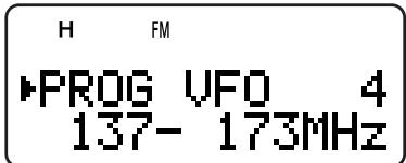
6 Press [▶] or [MNU].
7 Turn the Tuning control or press [] / [] to select the lower limit frequency in MHz.
8 Press [▶] or [MNU] to store the lower limit frequency. To cancel, press [<] or [PTT].
- The cursor moves to the right and the upper limit frequency blinks.
9 Turn the Tuning control or press [▲]/[▼] to select the upper limit frequency in MHz.
10 Press [▶] or [MNU] to store the upper limit frequency. To cancel, press [<] or [PTT].
Note:
Programmable VFO is available only for A-band.
You cannot program the 100kHz or lower digits.
The upper limit frequency cannot be selected lower than the selected lower limit frequency.
If you do not want to use the A and B-band receivers at the same time, you can turn the A or B-band receiver OFF.
1 Press [A/B] to select the band you want to operate.
2 Press [F], [A/B].
- The frequency of the selected band appears in large font and the other band receiver is turned OFF and muted.
- You can also press [A/B] to alternate the A and B-band.

3 To return to normal dual-band operation, press [F], [A/B] again.
TIME-OUT TIMER
The Time-out Timer limits the time of each transmission. The built-in time-out timer limits each transmission time to a maximum of 10 minutes. Just before the transceiver stops the transmission, a warning beep sounds. It is necessary to protect the transceiver from thermal damage. You cannot turn this function OFF.
Note: A warning beep sounds even if you select Menu No. 19 (KEY BEEP) OFF.
TONE ALERT
Tone Alert provides an audible alarm when signals are received on the frequency you are monitoring. In addition, it shows the number of hours and minutes elapsed after signals have been received. If you use Tone Alert with CTCSS or DCS, it sounds only when a received CTCSS tone or DCS code matches the tone or code you selected.
1 Select your desired frequency or memory channel.
2 Press [F], [ENT].
- “ 空 ” icon appears.
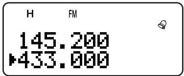
- When a signal is received, an alarm sounds for 10 seconds and “ ” icon starts blinking.
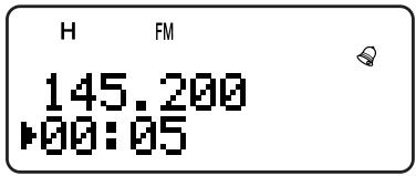
- Press [PTT] while “ 空 ” icon is blinking to turn the Tone Alert function OFF.
- When 99 hours and 59 minutes pass after a signal has been received, counting stops.
Each time a new signal is received, the elapsed time resets to 00:00.
Note:
While Tone Alert is ON, there is no speaker output when a signal is received. To monitor the signal, press and hold [MONI].
When Tone Alert is ON, APO does not turn the power OFF.
If you switch the transceiver OFF while ^ icon is blinking, the transceiver does not back the elapsed time.
When Tone Alert is ON, you can use only the following functions: [LAMP], [MONI], [SQL], [A/B], [F] then [LAMP], and [F] then [ENT].
TX INHIBIT
You can inhibit the transmission to prevent unauthorized individuals from transmitting, or to eliminate accidental transmissions while carrying the transceiver.
1 Press [MNU].
2 Turn the Tuning control or press [▲]/[▼] to select Menu No. 8 (TX INHIBIT).
3 Press [▶] or [MNU].
4 Turn the Tuning control or press [] / [] to select "ON".
5 Press [▶] or [MNU] to store the setting. Otherwise, press [<] or [PTT] to cancel.
- "TX INHIBIT!" appears and an error beep sounds if you press [PTT] while TX Inhibit is activated.
TX POWER
To change the transmission output power:
Press [LOW].
Each time you press [LOW], the icon cycles from H → L → EL, and then goes back to H.
The output power varies depending on the battery type and operating voltage. The table below shows the approximate output power when the transceiver operates with different types of battery or DC power source.
| Battery Type | Output Power Selection | Output Power (Approx.) |
| TH-F6A/ TH-F7E | ||
| BT-14 (6.0 V) | H | 0.5 W |
| L | 0.3 W | |
| EL | 0.05 W | |
| PB-42L (7.4 V) | H | 5.0 W |
| L | 0.5 W | |
| EL | 0.05 W | |
| DC IN (13.8 V) | H | 5.0 W |
| L | 2.0 W | |
| EL | 0.5 W |
Note:
You can store the TX Power settings independently for A and B-band.
If the DC IN voltage exceeds 14.5 V DC and "H" (High Power) is selected, "H" icon blinks and the output power is reduced to "L" level (Low Power) automatically.
VOLUME BALANCE
While you are receiving on the A and B-bands at the same time, you may sometimes feel that the audio output on either band is too loud. You can adjust the volume balance level of the bands.
1 Press [BAL].
- The balance scale and blinking cursor appear.
![KENWOOD TH-F7E - Press [BAL]. - 1](/content/2025/01/83302/images/286fc88e664a0fcdd4c6609a9de6d8d8301eb81448bd0cf878f0b509baa12679.jpg)
2 Turn the Tuning control or press [] / [] to change the volume balance level of the bands.
![KENWOOD TH-F7E - Press [BAL]. - 2](/content/2025/01/83302/images/b9ea1eb389a839166dff54643f9c63dacd03c2ded80c7c9c058959163614e806.jpg)
A-band
B-band
![KENWOOD TH-F7E - Press [BAL]. - 3](/content/2025/01/83302/images/8f295353b86fd7dda51119e5dbec29131b9f04df7c71cb5eceb742cff81462d0.jpg)
Max
Att
![KENWOOD TH-F7E - Press [BAL]. - 4](/content/2025/01/83302/images/ec45e597f6a42a964ca133440ccaaaf949085b756fac9175a15147fcc6d355ec.jpg)
Max
Max
![KENWOOD TH-F7E - Press [BAL]. - 5](/content/2025/01/83302/images/cd0a9bde30742057ad114bd1f884e67dde73991381abcb30448f26bd8e4bc57f.jpg)
Att
Max
![KENWOOD TH-F7E - Press [BAL]. - 6](/content/2025/01/83302/images/b25184c42f1ed714a6b03a8a1c330de3ec631ba7a4bcee7925bba237145f0870.jpg)
Mute
Max
Max: Maximum, Mute: Muted, Att: Attenuated
3 Press [▶] or [MNU] to store the setting.
Otherwise, press [<] to cancel without changing the current settings.
Note:
If TNC is selected for Menu No. 9 (SP/MIC JACK), the squelch status (REM/ SQ) changes based on your volume balance settings {pages 45, 46}.
You can also set the volume balance while in Single Band Operation{page 40}.
VOX (VOICE-OPERATED TRANSMIT)
VOX eliminates the necessity of manually switching to the transmit mode each time you want to transmit. The transceiver automatically switches to transmit mode when the VOX circuitry senses that you have begun speaking into the microphone.
When you operate the VOX function, you must use an optional accessory, HMC-3 or KHS-21. Because both the internal speaker and microphone are too near to be used for the VOX function.
To turn the VOX function ON:
Press [F], [SQL].
- "VOX" appears.
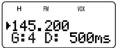
- To exit VOX mode, press [F], [SQL] again.
Note:
You cannot turn the VOX function ON while the Visual Scan {pages 26, 27} is activated.
While the VOX function is ON, the Menu No. 28 (PACKET) settings return to 1200 bps {page 45}.
While the VOX function is ON, you cannot use [] / [] / [] / [] to adjust other settings, such as the frequency and operating band.
While in the Menu mode {page 9}, the VOX function is disabled temporarily.
Since the VOX circuit must detect the presence of your voice, you may notice a slight delay in transmission. The very first part of your message may not be transmitted.
Turn the HMC-3's VOX function OFF when you use the internal VOX function.
VOX GAIN
To enjoy the VOX function, take the time to properly adjust the VOX Gain. This level controls the VOX circuit to detect the presence or absence of your voice. There are 2 ways of adjusting the VOX Gain.
When the VOX function is already ON:
1 Press [] / [] to select the desired VOX Gain from 0 (least sensitive) to 9 (most sensitive).
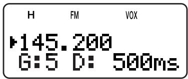
- The VOX Gain level numbers, "G: 4" changes accordingly (default is 4).
2 While speaking into the microphone using your normal tone of voice, adjust the VOX Gain by pressing [▲]/[▼] until the transceiver reliably switches to transmit mode each time you speak.
- The setting should not allow background noise to switch the transceiver to transmit mode.
11 OPERATOR CONVENIENCES
From the Menu:
1 Press [MNU].
2 Turn the Tuning control or press [▲]/[▼] to select Menu No. 21 (VOX GAIN).
3 Press [▶] or [MNU].
4 Turn the Tuning control or press [] / [] to select the desired VOX Gain (default is 4).
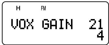
- The selectable gain range is from 0 (least sensitive) to 9 (most sensitive).
- The setting should not allow background noise to switch the transceiver to transmit mode.
5 Press [▶] or [MNU] to store the setting. Otherwise, press [←] or [PTT] to cancel.
VOX DELAY TIME
If the transceiver returns to receive mode too quickly after you stop speaking, your final word may not be transmitted. To avoid this, select an appropriate delay time that allows all of your words to be transmitted. However, do not make the delay overly long. There are 2 ways of adjusting the VOX Delay Time.
When the VOX function is already ON:
Press [←]/ [▶] to select the desired delay time from 250, 500 (default), 750, 1000, 1500, 2000 and 3000 ms.
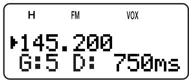
- The VOX Delay Time, "D: 500ms" changes accordingly.
From the Menu:
1 Press [MNU].
2 Turn the Tuning control or press [▲]/[▼] to select Menu No. 22 (VOX DELAY).
3 Press [▶] or [MNU].
4 Turn the Tuning control or press [▲]/[▼] to select the desired delay time from 250, 500 (default), 750, 1000, 1500, 2000 and 3000 ms.

5 Press [▶] or [MNU] to store the setting. Otherwise, press [←] or [PTT] to cancel.
Note:
If you press [PTT] while the VOX function is ON, the VOX Delay Time is not reflected to the transmission.
If you press [CALL] (if 1750 Hz is programmed) {page 13} to transmit 1750 Hz tone, the VOX Delay Time is not reflected.
If the DCS function {page 29} is ON, the transceiver remains in the transmission mode for the VOX Delay Time, then it sends "Turn-Off Code" to close the receiving parties squelch.
VOX ON BUSY
You can configure the transceiver to force VOX transmission even if the transceiver is receiving a signal on A or B-band.
1 Press [MNU].
2 Turn the Tuning control or press [▲]/[▼] to select Menu No. 20 (VOXonBUSY).
3 Press [▶] or [MNU].
4 Turn the Tuning control or press [▲]/[▼] to select "ON".

- To suppress the VOX transmission when the transceiver is receiving a signal, select "OFF".
5 Press [▶] or [MNU] to store the setting. Otherwise, press [←] or [PTT] to cancel.
Note: You can press [PTT] or [CALL] (if 1750 Hz is programmed) to transmit, regardless of Menu No. 20 (VOXonBUSY) settings.
If you also have a KENWOOD multi-band mobile transceiver, you can control one of its bands by sending DTMF tones from this portable transceiver. You will find this function useful when you want to control your mobile transceiver from a location outside your vehicle.
Note:
You can remotely control only mobile transceivers that have both the DTSS and Remote Control functions.
The FCC rules permit you to send control codes only on the 70 cm band.
PREPARATION
Let us assume the 2m band of the mobile transceiver will be controlled.
On the portable transceiver:
1 Press [PTT]+[VFO]+[Φ] (POWER).
- The current secret access code number appears. The default is 000.

2 Press a numeric key (0 to 9) to enter a 3-digit secret number.
-
You can also turn the Tuning control or press [▲]/[▼] to select each digit. Press [▶] (or [▲]) to move the cursor to the next (or previous) digit.
3 When the cursor is at the right most position, press [▶] to complete the setting.
4 Press [BAND] to select the 70 cm band.
5 Turn the Tuning control to select the transmit frequency.
6 Turn a transceiver power OFF.
7 Press [PTT]+[MR]+[ 念 ] (POwER). -
The transceiver enters Remote Control mode. "MOBILE CTRL" appears.

- To exit Remote Control mode, repeat steps 6 and 7.
On the mobile transceiver:
8 Program the DTSS code on the 70 cm band as the secret number.
- Select the same number as you selected in step 2.
- For the programming method, refer to the instruction manual of the mobile transceiver.
9 Select the receive frequency on the 70~cm band.
- Mate this frequency with the transmit frequency on the portable transceiver.
10 Make the transceiver enter Remote Control mode.
- For the method, refer to the instruction manual of the mobile transceiver.
CONTROL OPERATION
When in the Remote Control mode, the keys of the transceiver will function as below. Each time you press a key, the transceiver will automatically enter transmit mode and send the corresponding command to the mobile transceiver.
| 1 | 2 | 3 | A |
| REV ON¹ | TONE ON | CTCSS ON | ENT |
| 4 | 5 | 6 | B |
| REV OFF¹ | TONE OFF | CTCSS OFF | TONE SEL |
| 7 | 8 | 9 | C |
| CALL | VFO | MR | (REP ON)² |
| * | 0 | # | D |
| DOWN | LOW | UP | (REP OFF)² |
1 TM-V7A/ TM-D700A: REV ON/ OFF TS-2000/ TS-B2000: DCS ON/ OFF Other mobile transceiver: TONE ALERT ON/ OFF
Switches Repeater function ON/ OFF if the mobile transceiver supports this function.
To change the transmit/ receive frequency:
$$ \begin{array}{l} \text {[ V F O ]} \Rightarrow \text {[ E N T ]} \Rightarrow \text {[ 0 ]} \sim \text {[ 9 ] (e n t e r t h e n e c e s s a r y} \ \text {d i g i t s)} \Rightarrow \text {[ E N T ]} \end{array} $$
Or
$$ [ V F O ] \Rightarrow [ U P ] / [ D O W N ] $$
To recall a memory channel:
$$ \begin{array}{l} \text {[ M R ]} \Rightarrow \text {[ E N T ]} \Rightarrow \text {[ 0 ]} \sim \text {[ 9 ]} (\text {e n t e r t h e n e c e n s a r y d i g i t s}) \ \Rightarrow \text {[ E N T ]} \end{array} $$
Or
$$ [ \mathrm {M R} ] \Rightarrow [ \mathrm {U P} ] / [ \mathrm {D O W N} ] $$
To change the tone (or CTCSS) frequency:
$$ \begin{array}{l} \text {[ T O N E S E L ]} \Rightarrow [ 0 ] \sim [ 9 ] \text {(e n t e r 2 d i g i t s ; e x . [ 0 ] , [ 5 ])} \Rightarrow \ \text {[ T O N E S E L ]} \end{array} $$
- Refer to the Tone frequency table on your mobile transceiver for the Tone number.
- Your mobile transceiver may require you to first activate the Tone or CTCSS function. It may also allow you to program a separate tone and CTCSS frequency. Refer to the instruction manual of the mobile transceiver.
BT-13
Battery Case (4 AA/ LR6)

EMC-3
Clip Microphone with Earphone
HMC-3
Headset (with VOX/ PTT)

KHS-21
Headset
PB-42L
Li-ion Battery Pack (7.4 V, 1550 mAh)

PG-2W
DC Power Cable
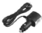
PG-3J
Cigarette Lighter Power Cable
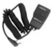
SMC-32
Speaker Microphone
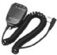
SMC-33
Speaker Microphone (with PF keys)
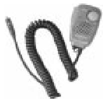
SMC-34
Speaker Microphone (with PF keys and VOL control)
SP/MIC JACK
The SP/MIC jack on the transceiver can be configured to interface to various kinds of the peripherals available for the transceiver, such as a speaker microphone (SMC-32/ 33/ 34), PC interface cable and a TNC. Access Menu No. 9 (SP/MIC JACK) and select the peripheral type from "SP/MIC", "TNC", and "PC".
You can further configure the transceiver to interface to a high speed (9600 bps) TNC that requires a direct FM modulation {below}.
SELECTING SP/MIC JACK FUNCTION
Unless you connect the transceiver to a TNC or PC, the default setting of the SP/MIC jack function (Menu No. 9), "SP/MIC" works fine. However, if you want to interface to a different type of peripheral, configure the SP/MIC jack function:
1 Press [MNU] to enter Menu mode.
2 Turn the Tuning control or press [▲]/[▼] to select Menu No. 9 (SP/MIC JACK).
3 Press [▶] or [MNU].
4 Turn the Tuning control or press [] / [] to select the appropriate peripheral type from "SP/MIC" (default), "TNC", and "PC".
| SP/MIC Function | Peripheral Type |
| SP/MIC | Speaker microphone, headset,earphone, TNC without a squelchstatus support |
| TNC | TNC with a squelch status support |
| PC | PC with the memory channel controlsoftware for the transceiver |
5 Press [▶] or [MNU] to store the setting. Otherwise, press [<] or [PTT] to cancel.
If necessary, configure and select the additional settings.
6 Press [ ] (POWER) to turn the transceiver OFF.
7 Connect a peripheral to the SP/MIC jack.
8 Press [ ] (POWER) to turn the transceiver ON.
SP/MIC
If you plug the speaker microphone or headset into the SP/MIC jack, access Menu No. 9 and select "SP/MIC" (default). To emulate the programmable function keys using external keys in order to control the transceiver, refer to the circuit diagram below {page 38}.
Note 1:
Voltage is developed across a 100 resistor on the 3.5 V line in the transceiver. When 2 mA flows, approximately 3.3 V is developed.
Note 2:
A 10~ F capacitor is not required in the following cases.
- When other equipment has DC blocking capacitors.
- When a 2-terminal electret condenser microphone is used.
TNC
If you want to utilize the squelch status on your TNC, access Menu No. 9 and select "TNC". From the TNC, make the interface cable that connects to SP/PRD, MIC/PKD, PTT, REM/SQ, and GND on the transceiver SP/MIC jack terminal. In addition, if your TNC supports 9600 bps packet (G3RUH/ GMSK 9600 bps modem), access Menu No. 28 (PACKET) and select "9600" bps. This option allows you to transmit/ receive packet signals in a direct FM modulation/ quadrature detector output. You must use the A-band to transmit and receive 9600 bps packet signal. The following diagram shows the available terminals on the SP/MIC jack for the TNC.
Note:
When you select 9600 bps for Menu No. 28 (PACKET), you cannot monitor the sound from the speaker. Select 1200 bps for Menu No. 28 (PACKET) when you return to normal operation.
While the VOX function is turned ON, Menu No. 28 (PACKET) returns to 1200 bps {page 41}.
14 INTERFACING TO PERIPHERALS
Since the transceiver can receive 2 different frequencies, it outputs the squelch status (REM/SQ) as shown the table below.
Press [BAL] to set the Volume balance {page 41}.
| VOL Balance | REM/SQ Sensing Band |
| A-band | A-band and/or B-band (logic sum) |
| B-band | B-band |
PC
If you want to connect the transceiver to a PC in order to manage the memory channels in the transceiver, you need an interface cable. You will also need the supported software to download, upload, and edit the memory channel contents of the transceiver.
To manage the memory contents in the transceiver from a PC, access Menu No. 9 and select "PC".
For your information, the following diagram shows how the TH-F6A/ TH-F7E communicates to the PC using a serial (COM) port.
Note: Contact an authorized dealer for the PC Interface cable availability.
GENERAL INFORMATION
Your transceiver has been factory aligned and tested to specification before shipment. Under normal circumstances, the transceiver will operate in accordance with these operating instructions. All adjustable trimmers, coils and resistors in the transceiver were preset at the factory. They should only be readjusted by a qualified technician who is familiar with this transceiver and has the necessary test equipment. Attempting service or alignment without factory authorization can void the transceiver warranty.
When operated properly, the transceiver will provide years of service and enjoyment without requiring further realignment. The information in this section gives some general service procedures requiring little or no test equipment.
SERVICE
If it is ever necessary to return the equipment to your dealer or service center for repair, pack the transceiver in its original box and packing material. Include a full description of the problems experienced. Include your telephone number, fax number, and email address (if available) along with your name and address in case the service technician needs to contact you for further explanation while investigating your problem. Do not return accessory items unless you feel they are directly related to the service problem.
You may return your transceiver for service to the authorized KENWOOD dealer from whom you purchased it or any authorized KENWOOD service center. A copy of the service report will be returned with the transceiver. Please do not send subassemblies or printed circuit boards. Send the complete transceiver.
Tag all returned items with your name and call sign for identification. Please mention the model and serial number of the transceiver in any communication regarding the problem.
SERVICE NOTE
If you desire to correspond on a technical or operational problem, please make your note short, complete, and to the point. Help us help you by providing the following:
1 Model and serial number of equipment.
2 Question or problem you are having.
3 Other equipment in your station pertaining to the problem.
4 Meter readings.
5 Other related information (menu setup, mode, frequency, key sequence to induce malfunction, etc).
CAUTION
DO NOT PACK THE EQUIPMENT IN CRUSHED NEWSPAPERS FOR SHIPMENT! EXTENSIVE DAMAGE MAY RESULT DURING ROUGH HANDLING OR SHIPPING.
Note:
Record the date of purchase, serial number and dealer from whom the transceiver was purchased.
For your own information, retain a written record of any maintenance performed on the transceiver.
When claiming warranty service, please include a photocopy of the bill of sale, or other proof-of-purchase showing the date of sale.
CLEANING
The keys, controls, and case of the transceiver are likely to become soiled after extended use. Remove the controls from the transceiver and clean them with a neutral detergent and warm water. Use a neutral detergent (no strong chemicals) and a damp cloth to clean the case.
BACKUP BATTERY
This transceiver uses an EEPROM to store memory channel data, menu configurations, and all necessary operation parameters. So, you never have to worry about replacing back-up batteries to operate the transceiver.
15 TROUBLESHOOTING
TROUBLESHOOTING
The problems described in the following table are commonly encountered operational malfunctions. These types of difficulties are usually caused by improper hook-up, accidental incorrect control settings, or operator error due to incomplete programming. These problems are usually not caused by circuit failure. Please review this table, and the appropriate section(s) of this instruction manual, before assuming your transceiver is defective.
Note: Placing powered PC peripherals near this transceiver may cause noise in the transceiver.
| Problem | Probable Cause | Corrective Action | Ref. Page |
| Nothing appears on the display when the transceiver is switched ON, or the display is blinking ON and OFF. | 1 The battery pack is discharged. | 1 Recharge the battery pack or replace the batteries. | 2 |
| 2 The protection circuit for the Li-ion battery pack is activated. | 2 Release the Li-ion battery pack once, then recharge the battery pack. | 2 | |
| 3 If using the optional DC cable: a) Bad power cable or connections | 3 a) Check the power cable and connections, then correct/ replace as necessary. | 2 | |
| b) Open (blown) power supply fuse | b) Investigate the cause for the open fuse. Replace the fuse. | 2 | |
| Most keys and the Tuning control do not function. | 1 Transceiver Lock is ON (the “-” icon is visible). | 1 Press [F] (1 s) to switch OFF Transceiver Lock. | 38 |
| 2 The transceiver is in Channel Display mode. | 2 Press [A/B]+[∅] (POWER) to exit Channel Display mode. | 21 | |
| 3 Tone Alert is ON (the “♀” icon is visible). | 3 Press [F], [ENT] to switch OFF Tone Alert. | 40 | |
| You cannot select the exact desired frequency using [4]/[7] or the Tuning control. | 1 The current frequency step size does not allow the frequency to be selected. | 1 Press [F], [FINE] to select an appropriate frequency step size. | 37 |
| 2 The Fine Tuning function is not activated. | 2 Press [FINE] to activate the Fine Tuning function. | 35 | |
| 3 The Fine Tuning frequency step size is wrong. | 3 While the Fine Tuning function is ON, press [F], [FINE] to select an appropriate Fine Tuning frequency steps size. | 35 | |
| 4 Programmable VFO frequency range is programmed. | 4 Access Menu No. 4 (PROG VFO) to expand the frequency range. | 39 | |
| You cannot recall any memory channels. | 1 You have stored no data in any of the memory channels using the current band. | 1 Store the desired frequencies in memory channels using the current band. | 15 |
| 2 “CURRENT BAND” is selected for Menu No. 3 (MR METHOD). | 2 Access Menu No. 3 (MR METHOD) and select “ALL BANDS”. | 16 | |
| The receiving sound volume is weak even if the signal is strong. | 1 Attenuator function is ON. | 1 Press [F], [MONI] to turn the Attenuator function OFF. | 36 |
| 2 The receiving station may be operating in narrow band FM bandwidth. | 2 Access Menu No. 29 (FM NARROW) and select “ON”. | 39 | |
| Turning the VOL control does not allow you to hear audio. | 1 The speaker for the band you want to monitor is muted. | 1 Press [BAL], then turn the Tuning control to adjust the volume balance between A and B-bands. | 41 |
| 2 The 9600 bps is selected for Menu No. 28 (PACKET) | 2 Select 1200 bps for Menu No. 28 (PACKET). | 45 | |
| You cannot transmit by pressing the PTT switch. | 1 You selected a frequency outside the allowable range. | 1 Select a frequency within the allowable transmit frequency range. | 7, 53 |
| 2 You selected a transmit offset that places the transmit frequency outside the limit. | 2 Press [F], [REV] repeatedly so neither “+” nor “-” is visible. | 12 | |
| 3 TX Inhibit is ON. | 3 Access Menu No. 8 (TX INHIBIT) and select “OFF”. | 40 | |
| 4 Tone Alert is ON. | 4 Press [F], [ENT] to switch OFF Tone Alert. | 40 | |
| 5 The battery pack voltage is too low to transmit. | 5 Charge or replace the battery pack. | 2, 36 | |
| Repeater cannot be accessed. | 1 Wrong tone frequency is selected. | 1 Press [F], [TONE] to select a proper repeater access tone. | 13 |
| 2 Wrong repeater offset frequency is selected. | 2 Access Menu No. 6 (OFFSET) and select an appropriate shift frequency. | 12 | |
| 3 Wrong shift direction is selected. | 3 Try other shift directions. | 12 | |
| DTMF tone cannot be transmitted. | DTMF Lock is ON. | Access Menu No. 14 (DTMF LOCK) and select “OFF”. | 32 |
| Repeater does not accept your DTMF tones. | DTMF tone duration is too short. | Access Menu No. 11 (DTMF SPD) and select “SLOW”. | 32 |
| Transceiver trasmits without pressing the PTT switch. | VOX function is ON. | Press [F], [SQL] to turn the VOX function OFF. | 41 |
| The transceiver switches OFF for no apparent reason. | The Automatic Power Off (APO) function is programmed. | Access Menu No. 18 (APO) and turn the APO function OFF. | 36 |
| The output power is reduced and the “H” icon blinks. | The temperature of the transceiver's chassis becomes too high to transmit at high output power. The internal thermal protection circuits lowered the output power level. | Turn the transceiver OFF or let the transceiver cool down in the receive mode for a while. | 51 |
| The transceiver returns to receive mode after a long transmission. | The transmission time exceeded 10 minutes. | The built-in time-out timer cancels the transmission if you continuously transmit for over 10 minutes. You cannot turn this function OFF. It is necessary to protect the transceiver from the thermal damage. | 40 |
| The scan function does not resume the scanning after the transceiver detects a signal. | You have selected “SEEK” for Menu No. 1 (SCAN RESUME). | Select either “TIME” or “CARRIER” for Menu No. 1 (SCAN RESUME). | 27 |
15 TROUBLESHOOTING
MICROPROCESSOR RESET
If your transceiver seems to be malfunctioning, resetting the microprocessor may solve the problem. The following 3 reset modes are available. When performing the reset, you may lose memory data and stored information. Back up or write down important data before performing the reset.
INITIAL SETTINGS
For each VFO, the factory defaults for the operating frequency and mode are as follows.
A-band: 144.000 MHz/ FM
B-band: 440.000 MHz/ FM (TH-F6A)
B-band: 430.000 MHz/ FM (TH-F7E)
The Memory channels have no data stored. Refer to pages 19 and 20 for the Call Channels and Information Channels default values.
VFO RESET
This resets the transceiver parameters excluding the Menu contents and Memory channel contents.
Note: Menu No. 4 (PROG VFO) and No. 6 (OFFSET) return to the factory default values.
MENURESET
This resets the parameters only in the Menu items to factory default values.
FULL RESET
This resets all transceiver parameters to the factory default values.
PERFORMING RESET
There are 2 ways to enter the reset mode selection. However, the transceiver must be configured to the Lock function OFF {page 38}.
When the transceiver is turned OFF:
1 Press [F] + [∅] (POWER).
- All indicators are lit.
2 Release [F].
- Proceed to step 3 {below}.
From the Menu:
1 Press [MNU].
2 Turn the Tuning control or press [▲]/[▼] to select Menu No. 31 (RESET?). Press [▶] or [MNU].
3 Select the reset mode by turning the Tuning control or press [▲]/[▼]. If you select "NO", the transceiver exits the reset mode.

4 Press [▶] or [MNU] to proceed.
- If you press any keys, other than [LAMP] and [MONI], the transceiver exits the reset mode.
- A reset confirmation message appears.

5 Press [▶] or [MNU] to reset the transceiver.
- If you press any keys, other than [LAMP] and [MONI], the transceiver exits the reset mode.
OPERATIONNOTICES
The transceiver has been designed and engineered to avoid possible hardware glitches. However, you may notice the following symptoms when you operate the transceiver. These symptoms are not malfunctions.
OPERATING VOLTAGE
As stated in "SPECIFICATIONS" {page 53}, this transceiver operates on a DC voltage from 5.5V 7.5V DC (battery terminal) or 12.0V 16.0V DC (DC IN jack). If you find that the transceiver cannot be switched ON, or "VOLTAGE ERROR" appears, the supplied power source may be outside of the specified range.
In such a case, remove the DC power cable from the transceiver immediately and confirm that the supplied voltage is within the specified range.
TUNING IN SSB/ CW MODE
The transceiver uses a general purpose IF filter to receive signals in LSB, USB, CW and AM modes. So, when you receive signals in LSB or USB mode, the opposite side band signal is not fully attenuated. At the same time, since the same filter is used for CW reception, you may have difficulties seperating the CW signal from other signals in the crowded band.
To best tune in to a SSB signal, follow the instruction below.
When you receive signals in USB mode:
1 Turn the Fine Tuning function ON {page 35}.
2 Tune to the target signal while starting at a lower frequency, using the Tuning control.
When you receive signals in LSB mode:
1 Turn the Fine Tuning function ON {page 35}.
2 Tune to the target signal while starting at a higher frequency, using the Tuning control.
RECEIVING IN AM BAND
If you receive a weak signal in AM band, you may notice a high pitched squealing noise in the background. This noise is generated by the internal DC/DC converter and it cannot be removed.
RECEIVING SIGNALS IN CITIES
When you receive signals in cities, the receiver's entire S-meter may light up without receiving any strong signals. This happens when the RF amplifier in the receiver is overloaded by strong interference signals that are nearby. In this case, turn the Attenuator function ON {page 36} to reduce the interference signal level. You may further have to adjust the volume level while receiving the target signal.
BEAT AND NOISE
When you have the same 2 m, 1.25 m (TH-F6A only), and 70 cm band frequencies for both A and B-band receivers, the Visual Scan may indicate the signals on the bar-graph display even if no signal is monitored on the A-band receiver. This error occurs due to the internal spurious harmonics that are generated by the B-band-receiver. Refer to "INTERNAL BEATS" {below} for the frequencies.
You may also hear some noise in the receiving signal in the following cases.
- You perform any scan on the other receiver.
- You perform the Visual Scan on the B-band receiver.
TRANSMISSION
If you continuously transmit for more than 3 minutes at high power (5 W), the transceiver becomes warm. If you continue or repeat the transmission before the transceiver cools down, the thermal protector automatically decreases the output power to 0.5 W. "H" also blinks at the same time. If this happens, let the transceiver cool down for a while before transmitting again.
INTERNAL BEATS
If one of the formulas on the next page is true, the S-meter moves without receiving any signals or you cannot receive any signals. This is inevitable when you use superheterodyne receivers.
15 TROUBLESHOOTING
Internal Beats Frequency Formula
When you receive a signal on the A-band within the 2m band;
(A-band receive freq. + 59.85 MHz) x 10 - (2 m band receive freq. on the B-band + 57.6 MHz) x 10 = ±59.85 MHz or ±57.6 MHz
(A-band receive freq. + 59.85 MHz) x 3 - (1.25 m band receive freq. on the B-band + 57.6 MHz) x 2 = ±59.85 MHz or ±57.6 MHz
(A-band receive freq. + 59.85 MHz) x 8 - (1.25 m band receive freq. on the B-band + 57.6 MHz) x 6 = ±59.85 MHz or ±57.6 MHz
(A-band receive freq. + 59.85 MHz) x 4 - (70 cm band receive freq. on the B-band - 57.6 MHz) x 2 = ±59.85 MHz or ±57.6 MHz
(A-band receive freq. + 59.85 MHz) x 6 - (70 cm band receive freq. on the B-band - 57.6 MHz) x 3 = ±59.85 MHz or ±57.6 MHz
(A-band receive freq. + 59.85 MHz) x 7 - (70 cm band receive freq. on the B-band - 57.6 MHz) x 4 = ±59.85 MHz or ±57.6 MHz
(A-band receive freq. + 59.85 MHz) x 9 - (70 cm band receive freq. on the B-band - 57.6 MHz) x 5 = ±59.85 MHz or ±57.6 MHz
(A-band receive freq. + 59.85 MHz) x 11 - (70 cm band receive freq. on the B-band - 57.6 MHz) x 6 = ±59.85 MHz or ±57.6 MHz
within the 1.25m band;
(A-band receive freq. + 59.85 MHz) x 6 - (2 m band receive freq. on the B-band + 57.6 MHz) x 8 = ±59.85 MHz or ±57.6 MHz
(A-band receive freq. + 59.85 MHz) x 7 - (2 m band receive freq. on the B-band + 57.6 MHz) x 10 = ±59.85 MHz or ±57.6 MHz
(A-band receive freq. + 59.85 MHz) x 8 - (2 m band receive freq. on the B-band + 57.6 MHz) x 11 = ±59.85 MHz or ±57.6 MHz
(A-band receive freq. + 59.85 MHz) x 11 - (1.25 m band receive freq. on the B-band + 57.6 MHz) x 11 = ±57.6 MHz
(A-band receive freq. + 59.85 MHz) x 12 - (1.25 m band receive freq. on the B-band + 57.6 MHz) x 12 = ±59.85 MHz or ±57.6 MHz
(A-band receive freq. + 59.85 MHz) x 7 - (70 cm band receive freq. on the B-band - 57.6 MHz) x 5 = ±59.85 MHz or ±57.6 MHz
(A-band receive freq. + 59.85 MHz) x 8 - (70 cm band receive freq. on the B-band - 57.6 MHz) x 6 = ±59.85 MHz or ±57.6 MHz
(A-band receive freq. + 59.85 MHz) x 11 - (70 cm band receive freq. on the B-band - 57.6 MHz) x 8 = ±59.85 MHz or ±57.6 MHz
(A-band receive freq. + 59.85 MHz) x 12 - (70 cm band receive freq. on the B-band - 57.6 MHz) x 9 = ±59.85 MHz or ±57.6 MHz
within the 70~cm band;
(A-band receive freq. - 59.85 MHz) x 2 - (2 m band receive freq. on the B-band + 57.6 MHz) x 4 = ±59.85 MHz or ±57.6 MHz
(A-band receive freq. - 59.85 MHz) x 3 - (2 m band receive freq. on the B-band + 57.6 MHz) x 6 = ±59.85 MHz or ±57.6 MHz
(A-band receive freq. - 59.85 MHz) x 4 - (2 m band receive freq. on the B-band + 57.6 MHz) x 7 = ±59.85 MHz or ±57.6 MHz
(A-band receive freq. - 59.85 MHz) x 4 - (2 m band receive freq. on the B-band + 57.6 MHz) x 8 = ±59.85 MHz or ±57.6 MHz
(A-band receive freq. - 59.85 MHz) x 5 - (2 m band receive freq. on the B-band + 57.6 MHz) x 9 = ±59.85 MHz or ±57.6 MHz
(A-band receive freq. - 59.85 MHz) x 6 - (2 m band receive freq. on the B-band + 57.6 MHz) x 11 = ±59.85 MHz or ±57.6 MHz
(A-band receive freq. - 59.85 MHz) x 2 - (1.25 m band receive freq. on the B-band + 57.6 MHz) x 3 = ±59.85 MHz
(A-band receive freq. - 59.85 MHz) x 5 - (1.25 m band receive freq. on the B-band + 57.6 MHz) x 7 = ±59.85 MHz or ±57.6 MHz
(A-band receive freq. - 59.85 MHz) x 6 - (1.25 m band receive freq. on the B-band + 57.6 MHz) x 8 = ±59.85 MHz or ±57.6 MHz
(A-band receive freq. - 59.85 MHz) x 8 - (1.25 m band receive freq. on the B-band + 57.6 MHz) x 11 = ±59.85 MHz or ±57.6 MHz
(A-band receive freq. - 59.85 MHz) x 5 - (70 cm band receive freq. on the B-band - 57.6 MHz) x 5 = ±59.85 MHz or ±57.6 MHz
(A-band receive freq. - 59.85 MHz) x 6 - (70 cm band receive freq. on the B-band - 57.6 MHz) x 6 = ±59.85 MHz or ±57.6 MHz
(A-band receive freq. - 59.85 MHz) x 7 - (70 cm band receive freq. on the B-band - 57.6 MHz) x 7 = ±59.85 MHz or ±57.6 MHz
(A-band receive freq. - 59.85 MHz) x 8 - (70 cm band receive freq. on the B-band - 57.6 MHz) x 8 = ±59.85 MHz or ±57.6 MHz
(A-band receive freq. - 59.85 MHz) x 9 - (70 cm band receive freq. on the B-band - 57.6 MHz) x 9 = ±59.85 MHz or ±57.6 MHz
(A-band receive freq. - 59.85 MHz) x 10 - (70 cm band receive freq. on the B-band - 57.6 MHz) x 10 = ±59.85 MHz or ±57.6 MHz
1 TH-F6A only
2 Excluding the TH-F6A
| General | TH-F6A | TH-F7E | |
| Number of memory channels | 400 channels + 35 special function memories | 400 channels + 34 special function memories | |
| Antenna impedance (Connector type) | 50Ω (SMA) | ||
| Operating Voltage | DC IN jack | DC 12.0 ~ 16.0 V (13.8 V nominal) | |
| Battery terminal | DC 5.5 ~ 7.5 V (7.4 V nominal) | ||
| Grounding method | Negative ground | ||
| Current | Transmit with H, 13.8 V (DC IN) | 2.0 A or less | |
| Transmit with H, 7.4 V (PB-42L) | 2.0 A or less | ||
| Transmit with L, 7.4 V (PB-42L) | 0.8 A or less | ||
| Transmit with EL, 7.4 V (PB-42L) | 0.5 A or less | ||
| Receive (no signal) | 100 mA (single band)/ 170 mA or less (dual-band) | ||
| Battery Saver ON (Average) | 30 mA (single band)/ 35 mA or less (dual-band) | ||
| Usable temperature range | -20°C ~ 60°C (-4°F ~ 140°F) -10°C ~ 50°C (+14°F ~ 122°F) with PB-42L | ||
| Frequency stability | Within ±8ppm (-20°C ~ 60°C) Within ±5ppm (-10°C ~ 50°C) | ||
| Dimensions (W x H x D Projections not included) | 58 x 87 x 30 mm/ 2.3" x 3.4" x 1.2" with the PB-42L 58 x 87 x 38 mm/ 2.3" x 3.4" x 1.5" with the BT-13 | ||
| Weight | Approx. 250 g/ 0.55 lb with the PB-42L Approx. 280 g/ 0.62 lb with the BT-13 | ||
| Transmitter | TH-F6A | TH-F7E | ||
| Transmit Mode | F3E (FM)/ F2D (FM) | |||
| Frequency range | 2 m band | 144 ~ 148 MHz | 144 ~ 146 MHz | |
| 1.25 m band | 222 ~ 225 MHz | N/A | ||
| 70 cm band | 430 ~ 450 MHz1 | 430 ~ 440 MHz | ||
| Output Power | 2 m band/1.25 m band/70 cm band | DC IN jack(13.8 V) | H: 5.0 W (approx.)L: 2.0 W (approx.)EL: 0.5 W (approx.) | |
| PB-42L(7.4 V) | H: 5.0 W (approx.)L: 0.5 W (approx.)EL: 0.05 W (approx.) | |||
| BT-14(6.0 V) | H: 0.5 W (approx.)L: 0.3 W (approx.)EL: 0.05 W (approx.) | |||
| Modulation | Reactance | |||
| Maximum frequency deviation | ±5 kHz (FM)/ ±2.5 kHz (NFM) | |||
| Spurious emissions (at high transmit power) | -60 dB or less | |||
| Microphone impedance | 2kΩ | |||
1 Specifications are guaranteed within 438 ~ 450 MHz.
16 SPECIFICATIONS
| Receiver | TH-F6A | TH-F7E | |
| Receive mode | A-band | F3E (FM)/ F2D (FM)/ F1D (FM) | |
| B-band | J3E (LSB, USB)/ A1A (CW): 0.1 MHz ≤ f < 470 MHzA3A (AM)/ F3E (FM)/ F2D (FM): 0.1 MHz ≤ f < 1.3 GHz | ||
| Circuit type | LSB/ USB/ CW/ AM/ FM | Double superheterodyne | |
| WFM | Single superheterodyne | ||
| Frequency range | A-band | 137 ~ 174 MHz216 ~ 260 MHz410 ~ 470 MHz | 144 ~ 146 MHz430 ~ 440 MHz |
| B-band | 0.1 ~ 1.8 MHz1.8 ~ 29.7 MHz29.7 ~ 54 MHz54 ~ 108 MHz108 ~ 137 MHz137 ~ 174 MHz174 ~ 216 MHz216 ~ 400 MHz400 ~ 470 MHz470 ~ 806 MHz806 ~ 824 MHz849 ~ 869 MHz894 ~ 1300 MHz | 0.1 ~ 1.71 MHz1.71 ~ 29.7 MHz29.7 ~ 87.5 MHz87.5 ~ 108 MHz108 ~ 137 MHz137 ~ 174 MHz174 ~ 230 MHz230 ~ 400 MHz400 ~ 470 MHz470 ~ 862 MHz862 ~ 1300 MHz | |
| Intermediate Frequency (IF) | A-band | 1st IF: 59.85 MHz2nd IF: 450 kHz | |
| B-band | 1st IF0.1 MHz ~ 1.3 GHz: 57.60 MHz (LSB/ USB/ CW/ AM/ FM)29.7 MHz ~ 1.3 GHz: 10.8 MHz (WFM)2nd IF0.1 MHz ~ 1.3 GHz: 450 kHz (LSB/ USB/ CW/ AM/ FM) | ||
| Sensitivity | A-band | FM (12 dB SINAD)2m/ 1.25 m (TH-F6A only)/ 70 cm amateur radio bands:0.18 μV or less | |
| B-band | FM (12 dB SINAD)5 ~ 108 MHz: 0.40 μV118 ~ 144 MHz: 0.28 μV144 ~ 225 MHz: 0.22 μV225 ~ 250 MHz: 0.89 μV380 ~ 400 MHz: 0.40 μV400 ~ 450 MHz: 0.22 μV450 ~ 520 MHz: 0.40 μV520 ~ 700 MHz: 7.08 μV800 ~ 950 MHz: 1.26 μV950 ~ 1300 MHz: 0.40 μVWFM (30 dB S/N)50 ~ 108 MHz: 3.16 μV150 ~ 222 MHz: 2.82 μV400 ~ 500 MHz: 3.98 μV | AM (10 dB S/N)0.3 ~ 0.52 MHz: 7.08 μV0.52 ~ 1.8 MHz: 2.24 μV1.8 ~ 50 MHz: 0.89 μV118 ~ 250 MHz: 0.40 μV380 ~ 500 MHz: 0.40 μVLSB/ USB (10 dB S/N)3 ~ 30 MHz: 0.45 μV30 ~ 50 MHz: 0.40 μV144 ~ 148 MHz: 0.22 μV430 ~ 450 MHz: 0.22 μV* All values are approximate | |
| Squelch sensitivity | 0.13 μV or less(within 2m/ 1.25 m/ 70 cm amateur radio bands) | ||
| Selectivity | -6 dB/ 12 kHz or less-40 dB/ 28 kHz or less(within 2m/ 1.25 m/ 70 cm amateur radio bands) | ||
| Audio output (10% distortion) | 300 mW or higher (7.4 V, 8Ω load) | ||
TV CHANNELS (VHF)
U.S.A.
| CH No. | V Freq. (MHz) | A Freq. (MHz) |
| 2 | 55.25 | 59.75 |
| 3 | 61.25 | 65.75 |
| 4 | 67.25 | 71.75 |
| 5 | 77.25 | 81.75 |
| 6 | 83.25 | 87.75 |
| 7 | 175.25 | 179.75 |
| 8 | 181.25 | 185.75 |
| 9 | 187.25 | 191.75 |
| 10 | 193.25 | 197.75 |
| 11 | 199.25 | 203.75 |
| 12 | 205.25 | 209.75 |
| 13 | 211.25 | 215.75 |
United Kingdom
| CH No. | V Freq. (MHz) | A Freq. (MHz) |
| 1 | 45.00 | 41.50 |
| 2 | 51.75 | 48.25 |
| 3 | 56.75 | 53.25 |
| 4 | 61.75 | 58.25 |
| 5 | 66.75 | 63.25 |
| 6 | 179.75 | 176.25 |
| 7 | 184.75 | 181.25 |
| 8 | 189.75 | 186.25 |
| 9 | 194.75 | 191.25 |
| 10 | 199.75 | 196.25 |
| 11 | 204.75 | 201.25 |
| 12 | 209.75 | 206.25 |
| 13 | 214.75 | 211.25 |
France
| CH No. | V Freq. (MHz) | A Freq. (MHz) |
| A | 47.75 | 41.25 |
| B | 55.75 | 49.25 |
| C1 | 60.50 | 54.00 |
| C | 63.75 | 57.25 |
| 1 | 176.00 | 182.50 |
| 2 | 184.00 | 190.50 |
| 3 | 192.00 | 198.50 |
| 4 | 200.00 | 206.50 |
| 5 | 208.00 | 214.50 |
| 6 | 216.00 | 222.50 |
Italy
| CH No. | V Freq. (MHz) | A Freq. (MHz) |
| A | 53.75 | 59.25 |
| B | 62.25 | 67.75 |
| C | 82.25 | 87.75 |
| D | 175.25 | 180.75 |
| E | 183.75 | 189.25 |
| F | 192.25 | 197.75 |
| G | 201.25 | 206.75 |
| H | 210.25 | 215.75 |
| H1 | 217.25 | 222.75 |
| H2 | 224.25 | 229.75 |
Western Europe
| CH No. | V Freq. (MHz) | A Freq. (MHz) |
| 1 | 41.25 | 46.75 |
| 2 | 48.25 | 53.75 |
| 3 | 55.25 | 60.75 |
| 4 | 62.25 | 67.75 |
| 5 | 175.25 | 180.75 |
| 6 | 182.25 | 187.75 |
| 7 | 189.25 | 194.75 |
| 8 | 196.25 | 201.75 |
| 9 | 203.25 | 208.75 |
| 10 | 210.25 | 215.75 |
| 11 | 217.25 | 222.75 |
| 12 | 224.25 | 229.75 |
Ireland
| CH No. | V Freq. (MHz) | A Freq. (MHz) |
| A | 45.75 | 51.75 |
| B | 53.75 | 59.75 |
| C | 61.75 | 67.75 |
| D | 175.25 | 181.25 |
| E | 183.25 | 189.25 |
| F | 191.25 | 197.25 |
| G | 199.25 | 205.25 |
| H | 207.25 | 213.25 |
| J | 215.25 | 221.25 |
Eastern Europe
| CH No. | V Freq. (MHz) | A Freq. (MHz) |
| 1 | 49.75 | 56.25 |
| 2 | 59.25 | 65.75 |
| 3 | 77.25 | 83.75 |
| 4 | 85.25 | 91.75 |
| 5 | 93.25 | 99.75 |
| 6 | 175.25 | 181.75 |
| 7 | 183.25 | 189.75 |
| 8 | 191.25 | 197.75 |
| 9 | 199.25 | 205.75 |
| 10 | 207.25 | 213.75 |
| 11 | 215.25 | 221.75 |
| 12 | 223.25 | 229.75 |
French Affiliated Countries
| CH No. | V Freq. (MHz) | A Freq. (MHz) |
| 4 | 175.25 | 181.75 |
| 5 | 183.25 | 189.75 |
| 6 | 191.25 | 197.75 |
| 7 | 199.25 | 205.75 |
| 8 | 207.25 | 213.75 |
| 9 | 215.25 | 221.75 |
Morocco
| CH No. | V Freq. (MHz) | A Freq. (MHz) |
| 4 | 163.25 | 168.75 |
| 5 | 171.25 | 176.75 |
| 6 | 179.25 | 184.75 |
| 7 | 187.25 | 192.75 |
| 8 | 195.25 | 200.75 |
| 9 | 203.25 | 208.75 |
| 10 | 211.25 | 216.75 |
Angola
| CH No. | V Freq. (MHz) | A Freq. (MHz) |
| 1 | 43.25 | 49.25 |
| 2 | 52.25 | 58.25 |
| 3 | 60.25 | 66.25 |
| 4 | 175.25 | 181.25 |
| 5 | 183.25 | 189.25 |
| 6 | 191.25 | 197.25 |
| 7 | 199.25 | 205.25 |
| 8 | 207.25 | 213.25 |
| 9 | 215.25 | 221.25 |
| 10 | 223.25 | 229.25 |
South Africa
| CH No. | V Freq. (MHz) | A Freq. (MHz) |
| 4 | 175.25 | 181.25 |
| 5 | 183.25 | 189.25 |
| 6 | 191.25 | 197.25 |
| 7 | 199.25 | 205.25 |
| 8 | 207.25 | 213.25 |
| 9 | 215.25 | 221.25 |
| 10 | 223.25 | 229.25 |
| 11 | 231.25 | 237.25 |
| 12 | — | — |
| 13 | 247.43 | 253.43 |
China
| CH No. | V Freq. (MHz) | A Freq. (MHz) |
| 1 | 49.75 | 56.25 |
| 2 | 57.75 | 64.25 |
| 3 | 65.75 | 72.25 |
| 4 | 77.25 | 83.75 |
| 5 | 85.25 | 91.75 |
| 6 | 168.25 | 174.75 |
| 7 | 176.25 | 182.75 |
| 8 | 184.25 | 190.75 |
| 9 | 192.25 | 198.75 |
| 10 | 200.25 | 206.75 |
| 11 | 208.25 | 214.75 |
| 12 | 216.25 | 222.75 |
Japan
| CH No. | V Freq. (MHz) | A Freq. (MHz) |
| 1 | 91.25 | 95.75 |
| 2 | 97.25 | 101.75 |
| 3 | 103.25 | 107.75 |
| 4 | 171.25 | 175.75 |
| 5 | 177.25 | 181.75 |
| 6 | 183.25 | 187.75 |
| 7 | 189.25 | 193.75 |
| 8 | 193.25 | 197.75 |
| 9 | 199.25 | 203.75 |
| 10 | 205.25 | 209.75 |
| 11 | 211.25 | 215.75 |
| 12 | 217.25 | 221.75 |
Indonesia
| CH No. | V Freq. (MHz) | A Freq. (MHz) |
| 1A | 44.25 | 49.75 |
| 2 | 55.25 | 60.75 |
| 3 | 62.25 | 67.75 |
| 4 | 175.25 | 180.75 |
| 5 | 182.25 | 187.75 |
| 6 | 189.25 | 194.75 |
| 7 | 196.25 | 201.75 |
| 8 | 203.25 | 208.75 |
| 9 | 210.25 | 215.75 |
| 10 | 217.25 | 222.75 |
| 11 | 224.25 | 229.75 |
Australia
| CH No. | V Freq. (MHz) | A Freq. (MHz) |
| 0 | 46.25 | 51.75 |
| 1 | 57.25 | 62.75 |
| 2 | 64.25 | 69.75 |
| 3 | 86.25 | 91.75 |
| 4 | 95.25 | 100.75 |
| 5 | 102.25 | 107.75 |
| 5A | 138.25 | 143.75 |
| 6 | 175.25 | 180.75 |
| 7 | 182.25 | 187.75 |
| 8 | 189.25 | 194.75 |
| 9 | 196.25 | 201.75 |
| 10 | 209.25 | 214.75 |
| 11 | 216.25 | 221.75 |
New Zealand
| CH No. | V Freq. (MHz) | A Freq. (MHz) |
| 1 | 45.25 | 50.75 |
| 2 | 55.25 | 60.75 |
| 3 | 62.25 | 67.75 |
| 4 | 175.25 | 180.75 |
| 5 | 182.25 | 187.75 |
| 6 | 189.25 | 194.75 |
| 7 | 196.25 | 201.75 |
| 8 | 203.25 | 208.75 |
| 9 | 210.25 | 215.75 |
| 10 | 217.25 | 222.75 |
| 11 | 224.25 | 229.75 |
17 APPENDIX
TV CHANNELS (UHF)
U.S.A./Japan
| CH No. (U.S.A.) | CH No. (Japan) | V Freq. (MHz) | A Freq. (MHz) |
| 14 | 13 | 471.25 | 475.75 |
| 15 | 14 | 477.25 | 481.75 |
| 16 | 15 | 483.25 | 487.75 |
| 17 | 16 | 489.25 | 493.75 |
| 18 | 17 | 495.25 | 499.75 |
| 19 | 18 | 501.25 | 505.75 |
| 20 | 19 | 507.25 | 511.75 |
| 21 | 20 | 513.25 | 517.75 |
| 22 | 21 | 519.25 | 523.75 |
| 23 | 22 | 525.25 | 529.75 |
| 24 | 23 | 531.25 | 535.75 |
| 25 | 24 | 537.25 | 541.75 |
| 26 | 25 | 543.25 | 547.75 |
| 27 | 26 | 549.25 | 553.75 |
| 28 | 27 | 555.25 | 559.75 |
| 29 | 28 | 561.25 | 565.75 |
| 30 | 29 | 567.25 | 571.75 |
| 31 | 30 | 573.25 | 577.75 |
| 32 | 31 | 579.25 | 583.75 |
| 33 | 32 | 585.25 | 589.75 |
| 34 | 33 | 591.25 | 595.75 |
| 35 | 34 | 597.25 | 601.75 |
| 36 | 35 | 603.25 | 607.75 |
| 37 | 36 | 609.25 | 613.75 |
| 38 | 37 | 615.25 | 619.75 |
| 39 | 38 | 621.25 | 625.75 |
| 40 | 39 | 627.25 | 631.75 |
| 41 | 40 | 633.25 | 637.75 |
| 42 | 41 | 639.25 | 643.75 |
| 43 | 42 | 645.25 | 649.75 |
| 44 | 43 | 651.25 | 655.75 |
| 45 | 44 | 657.25 | 661.75 |
| 46 | 45 | 663.25 | 667.75 |
| 47 | 46 | 669.25 | 673.75 |
| 48 | 47 | 675.25 | 679.75 |
| 49 | 48 | 681.25 | 685.75 |
| 50 | 49 | 687.25 | 691.75 |
| 51 | 50 | 693.25 | 697.75 |
| 52 | 51 | 699.25 | 703.75 |
| 53 | 52 | 705.25 | 709.75 |
| 54 | 53 | 711.25 | 715.75 |
| 55 | 54 | 717.25 | 721.75 |
| 56 | 55 | 723.25 | 727.75 |
| 57 | 56 | 729.25 | 733.75 |
| 58 | 57 | 735.25 | 739.75 |
| 59 | 58 | 741.25 | 745.75 |
| 60 | 59 | 747.25 | 751.75 |
| 61 | 60 | 753.25 | 757.75 |
| 62 | 61 | 759.25 | 763.75 |
| 63 | 62 | 765.25 | 769.75 |
| 64 | 771.25 | 775.75 | |
| 65 | 777.25 | 781.75 | |
| 66 | 783.25 | 787.75 | |
| 67 | 789.25 | 793.75 | |
| 68 | 795.25 | 799.75 | |
| 69 | 801.25 | 805.75 | |
| 70 | 807.25 | 811.75 | |
| 71 | 813.25 | 817.75 | |
| 72 | 819.25 | 823.75 | |
| 73 | 825.25 | 829.75 | |
| 74 | 831.25 | 835.75 | |
| 75 | 837.25 | 841.75 | |
| 76 | 843.25 | 847.75 | |
| 77 | 849.25 | 853.75 | |
| 78 | 855.25 | 859.75 | |
| 79 | 861.25 | 865.75 | |
| 80 | 867.25 | 871.75 | |
| 81 | 873.25 | 877.75 | |
| 82 | 879.25 | 883.75 | |
| 83 | 885.25 | 889.75 |
Europe and Africa
| CH No. | V Freq. (MHz) | A Freq. (MHz) |
| 21 | 471.25 | 476.75 |
| 22 | 479.25 | 484.75 |
| 23 | 487.25 | 492.75 |
| 24 | 495.25 | 500.75 |
| 25 | 503.25 | 508.75 |
| 26 | 511.25 | 516.75 |
| 27 | 519.25 | 524.75 |
| 28 | 527.25 | 532.75 |
| 29 | 535.25 | 540.75 |
| 30 | 543.25 | 548.75 |
| 31 | 551.25 | 556.75 |
| 32 | 559.25 | 564.75 |
| 33 | 567.25 | 572.75 |
| 34 | 575.25 | 580.75 |
| 35 | 583.25 | 588.75 |
| 36 | 591.25 | 596.75 |
| 37 | 599.25 | 604.75 |
| 38 | 607.25 | 612.75 |
| 39 | 615.25 | 620.75 |
| 40 | 623.25 | 628.75 |
| 41 | 631.25 | 636.75 |
| 42 | 639.25 | 644.75 |
| 43 | 647.25 | 652.75 |
| 44 | 655.25 | 660.75 |
| 45 | 663.25 | 668.75 |
| 46 | 671.25 | 676.75 |
| 47 | 679.25 | 684.75 |
| 48 | 687.25 | 692.75 |
| 49 | 695.25 | 700.75 |
| 50 | 703.25 | 708.75 |
| 51 | 711.25 | 716.75 |
| 52 | 719.25 | 724.75 |
| 53 | 727.25 | 732.75 |
| 54 | 735.25 | 740.75 |
| 55 | 743.25 | 748.75 |
| 56 | 751.25 | 756.75 |
| 57 | 759.25 | 764.75 |
| 58 | 767.25 | 772.75 |
| 59 | 775.25 | 780.75 |
| 60 | 783.25 | 788.75 |
| 61 | 791.25 | 796.75 |
| 62 | 799.25 | 804.75 |
| 63 | 807.25 | 812.75 |
| 64 | 815.25 | 820.75 |
| 65 | 823.25 | 828.75 |
| 66 | 831.25 | 836.75 |
| 67 | 839.25 | 844.75 |
| 68 | 847.25 | 852.75 |
| 69 | 855.25 | 860.75 |
Note: 3 different types exist.
1: V Freq. + 5.5 MHz = A Freq. (above)
2:V Freq. +6.0MHz = A Freq.
3: V Freq. + 6.5 MHz = A Freq.
China
| CH No. | V Freq. (MHz) | A Freq. (MHz) |
| 13 | 471.25 | 477.75 |
| 14 | 479.25 | 485.75 |
| 15 | 487.25 | 493.75 |
| 16 | 495.25 | 501.75 |
| 17 | 503.25 | 509.75 |
| 18 | 511.25 | 517.75 |
| 19 | 519.25 | 525.75 |
| 20 | 527.25 | 533.75 |
| 21 | 535.25 | 541.75 |
| 22 | 543.25 | 549.75 |
| 23 | 551.25 | 557.75 |
| 24 | 559.25 | 565.75 |
| 25 | 607.25 | 613.75 |
| 26 | 615.25 | 621.75 |
| 27 | 623.25 | 629.75 |
| 28 | 631.25 | 637.75 |
| 29 | 639.25 | 645.75 |
| 30 | 647.25 | 653.75 |
| 31 | 655.25 | 661.75 |
| 32 | 663.25 | 669.75 |
| 33 | 671.25 | 677.75 |
| 34 | 679.25 | 685.75 |
| 35 | 687.25 | 693.75 |
| 36 | 695.25 | 701.75 |
| 37 | 703.25 | 709.75 |
| 38 | 711.25 | 717.75 |
| 39 | 719.25 | 725.75 |
| 40 | 727.25 | 733.75 |
| 41 | 735.25 | 741.75 |
| 42 | 743.25 | 749.75 |
| 43 | 751.25 | 757.75 |
| 44 | 759.25 | 765.75 |
| 45 | 767.25 | 773.75 |
| 46 | 775.25 | 781.75 |
| 47 | 783.25 | 789.75 |
| 48 | 791.25 | 797.75 |
| 49 | 799.25 | 805.75 |
| 50 | 807.25 | 813.75 |
| 51 | 815.25 | 821.75 |
| 52 | 823.25 | 829.75 |
| 53 | 831.25 | 837.75 |
| 54 | 839.25 | 845.75 |
| 55 | 847.25 | 853.75 |
| 56 | 855.25 | 861.75 |
| 57 | 863.25 | 869.75 |
| 58 | 871.25 | 877.75 |
| 59 | 879.25 | 885.75 |
| 60 | 887.25 | 893.75 |
| 61 | 895.25 | 901.75 |
| 62 | 903.25 | 909.75 |
| 63 | 911.25 | 917.75 |
| 64 | 919.25 | 925.75 |
| 65 | 927.25 | 933.75 |
| 66 | 935.25 | 941.75 |
| 67 | 943.25 | 949.75 |
| 68 | 951.25 | 957.75 |
Australia
| CH No. | V Freq. (MHz) | A Freq. (MHz) |
| 28 | 527.25 | 532.75 |
| 29 | 534.25 | 539.75 |
| 30 | 541.25 | 546.75 |
| 31 | 548.25 | 553.75 |
| 32 | 555.25 | 560.75 |
| 33 | 562.25 | 567.75 |
| 34 | 569.25 | 574.75 |
| 35 | 576.25 | 581.75 |
| 36 | 583.25 | 588.75 |
| 37 | 590.25 | 595.75 |
| 38 | 597.25 | 602.75 |
| 39 | 604.25 | 609.75 |
| 40 | 611.25 | 616.75 |
| 41 | 618.25 | 623.75 |
| 42 | 625.25 | 630.75 |
| 43 | 632.25 | 637.75 |
| 44 | 639.25 | 644.75 |
| 45 | 646.25 | 651.75 |
| 46 | 653.25 | 658.75 |
| 47 | 660.25 | 665.75 |
| 48 | 667.25 | 672.75 |
| 49 | 674.25 | 679.75 |
| 50 | 681.25 | 686.75 |
| 51 | 688.25 | 693.75 |
| 52 | 695.25 | 700.75 |
| 53 | 702.25 | 707.75 |
| 54 | 709.25 | 714.75 |
| 55 | 716.25 | 721.75 |
| 56 | 723.25 | 728.75 |
| 57 | 730.25 | 735.75 |
| 58 | 737.25 | 742.75 |
| 59 | 744.25 | 749.75 |
| 60 | 751.25 | 756.75 |
| 61 | 758.25 | 763.75 |
| 62 | 765.25 | 770.75 |
| 63 | 772.25 | 777.75 |
| 64 | 779.25 | 784.75 |
| 65 | 786.25 | 791.75 |
| 66 | 793.25 | 798.75 |
| 67 | 800.25 | 805.75 |
| 68 | 807.25 | 812.75 |
| 69 | 814.25 | 819.75 |
MARINE CHANNELS (VHF)
International
| CH No. | Frequency (MHz) | |
| TX | RX | |
| 1 | 156.050 | 160.650 |
| 2 | 156.100 | 160.700 |
| 3 | 156.150 | 160.750 |
| 4 | 156.200 | 160.800 |
| 5 | 156.250 | 160.850 |
| 6 | 156.300 | |
| 7 | 156.350 | 160.950 |
| 8 | 156.400 | |
| 9 | 156.450 | |
| 10 | 156.500 | |
| 11 | 156.550 | |
| 12 | 156.600 | |
| 13 | 156.650 | |
| 14 | 156.700 | |
| 15 | 156.750 | |
| 16 | 156.800 | |
| 17 | 156.850 | |
| 18 | 156.900 | 161.500 |
| 19 | 156.950 | 161.550 |
| 20 | 157.000 | 161.600 |
| 21 | 157.050 | 161.650 |
| 22 | 157.100 | 161.700 |
| 23 | 157.150 | 161.750 |
| 24 | 157.200 | 161.800 |
| 25 | 157.250 | 161.850 |
| 26 | 157.300 | 161.900 |
| 27 | 157.350 | 161.950 |
| 28 | 157.400 | 162.000 |
| CH No. | Frequency (MHz) | |
| TX | RX | |
| 60 | 156.025 | 160.625 |
| 61 | 156.075 | 160.675 |
| 62 | 156.125 | 160.725 |
| 63 | 156.175 | 160.775 |
| 64 | 156.225 | 160.825 |
| 65 | 156.275 | 160.875 |
| 66 | 156.325 | 160.925 |
| 67 | 156.375 | |
| 68 | 156.425 | |
| 69 | 156.475 | |
| 70 | 156.525 | |
| 71 | 156.575 | |
| 72 | 156.625 | |
| 73 | 156.675 | |
| 74 | 156.725 | |
| 76 | 156.825 | |
| 77 | 156.875 | |
| 78 | 156.925 | 161.525 |
| 79 | 156.975 | 161.575 |
| 80 | 157.025 | 161.625 |
| 81 | 157.075 | 161.675 |
| 82 | 157.125 | 161.725 |
| 83 | 157.175 | 161.775 |
| 84 | 157.225 | 161.825 |
| 85 | 157.275 | 161.875 |
| 86 | 157.325 | 161.925 |
| 87 | 157.375 | 161.975 |
| 88 | 157.425 | 162.025 |
Canada
| CH No. | Frequency (MHz) | |
| TX | RX | |
| 1 | 156.050 | 160.650 |
| 2 | 156.100 | 160.700 |
| 3 | 156.150 | 160.750 |
| 4 | 156.200 | |
| 5 | 156.250 | |
| 6 | 156.300 | |
| 7 | 156.350 | |
| 8 | 156.400 | |
| 9 | 156.450 | |
| 10 | 156.500 | |
| 11 | 156.550 | |
| 12 | 156.600 | |
| 13 | 156.650 | |
| 14 | 156.700 | |
| 15 | 156.750 | |
| 16 | 156.800 | |
| 17 | 156.850 | |
| 18 | 156.900 | |
| 19 | 156.950 | |
| 20 | 157.000 | 161.600 |
| 21 | 157.050 | |
| 22 | 157.100 | |
| 23 | 157.150 | 161.750 |
| 24 | 157.200 | 161.800 |
| 25 | 157.250 | 161.850 |
| 26 | 157.300 | 161.900 |
| 27 | 157.350 | 161.950 |
| 28 | 157.400 | 162.000 |
| CH No. | Frequency (MHz) | |
| TX | RX | |
| 60 | 156.025 | 160.625 |
| 61 | 156.075 | |
| 62 | 156.125 | |
| 63 | 156.175 | |
| 64 | 156.225 | 160.825* |
| 65 | 156.275 | |
| 66 | 156.325 | |
| 67 | 156.375 | |
| 68 | 156.425 | |
| 69 | 156.475 | |
| 70 | 156.525 | |
| 71 | 156.575 | |
| 72 | 156.625 | |
| 73 | 156.675 | |
| 74 | 156.725 | |
| 76 | 156.825 | |
| 77 | 156.875 | |
| 78 | 156.925 | |
| 79 | 156.975 | |
| 80 | 157.025 | |
| 81 | 157.075 | |
| 82 | 157.125 | |
| 83 | 157.175 | |
| 84 | 157.225 | |
| 85 | 157.275 | 161.875 |
| 86 | 157.325 | 161.925 |
| 87 | 157.375 | 161.975 |
| 88 | 157.425 | 162.025 |
U.S.A.
| CH No. | Frequency (MHz) | |
| TX | RX | |
| 1 | 156.050 | |
| 5 | 156.250 | |
| 6 | 156.300 | |
| 7 | 156.350 | |
| 8 | 156.400 | |
| 9 | 156.450 | |
| 10 | 156.500 | |
| 11 | 156.550 | |
| 12 | 156.600 | |
| 13 | 156.650 | |
| 14 | 156.700 | |
| 15 | 156.750 | |
| 16 | 156.800 | |
| 17 | 156.850 | |
| 18 | 156.900 | |
| 19 | 156.950 | |
| 20 | 157.000 | 161.600 |
| 21 | 157.050 | |
| 22 | 157.100 | |
| 23 | 157.150 | |
| 24 | 157.200 | 161.800 |
| 25 | 157.250 | 161.850 |
| 26 | 157.300 | 161.900 |
| 27 | 157.350 | 161.950 |
| 28 | 157.400 | 162.000 |
| CH No. | Frequency (MHz) | |
| TX | RX | |
| 63 | 156.175 | |
| 64 | 160.825 | |
| 65 | 156.275 | |
| 66 | 156.325 | |
| 67 | 156.375 | |
| 68 | 156.425 | |
| 69 | 156.475 | |
| 70 | 156.525 | |
| 71 | 156.575 | |
| 72 | 156.625 | |
| 73 | 156.675 | |
| 74 | 156.725 | |
| 77 | 156.875 | |
| 78 | 156.925 | |
| 79 | 156.975 | |
| 80 | 157.025 | |
| 81 | 157.075 | |
| 82 | 157.125 | |
| 83 | 157.175 | |
| 84 | 157.225 | |
| 85 | 157.275 | 161.875 |
| 86 | 157.325 | 161.925 |
| 87 | 157.375 | 161.975 |
| 88 | 157.425 | |
CITIZEN BAND CHANNELS
U.S.A.
| CH No. | Frequency (MHz) |
| 1 | 26.965 |
| 2 | 26.975 |
| 3 | 26.985 |
| 4 | 27.005 |
| 5 | 27.015 |
| 6 | 27.025 |
| 7 | 27.035 |
| 8 | 27.055 |
| 9 | 27.065 |
| 10 | 27.075 |
| 11 | 27.085 |
| 12 | 27.105 |
| 13 | 27.115 |
| 14 | 27.125 |
| 15 | 27.135 |
| 16 | 27.155 |
| 17 | 27.165 |
| 18 | 27.175 |
| 19 | 27.185 |
| 20 | 27.205 |
| CH No. | Frequency (MHz) |
| 21 | 27.215 |
| 22 | 27.225 |
| 23 | 27.255 |
| 24 | 27.235 |
| 25 | 27.245 |
| 26 | 27.265 |
| 27 | 27.275 |
| 28 | 27.285 |
| 29 | 27.295 |
| 30 | 27.305 |
| 31 | 27.315 |
| 32 | 27.325 |
| 33 | 27.335 |
| 34 | 27.345 |
| 35 | 27.355 |
| 36 | 27.365 |
| 37 | 27.375 |
| 38 | 27.385 |
| 39 | 27.395 |
| 40 | 27.405 |
- Pacific coast only
A-band 6
All-channel Scan 24
Alkaline Batteries, Installing 1
APO (Auto Power OFF) 36
AM 34
AM Band 33, 34
ASC 14
Attenuator 36
Automatic Dialer 31
Automatic Repeater Offset 13
Automatic Simplex Check 14
B-band Frequency 6,33
Band Scan 22
Bar Antenna 34
Battery
Installing the Alkaline 1
Installing the Li-ion, pack 1
Life 36
Remaining 36
Saver 37
Type 36
Beat Shift 37
Beep Function 37
Belt Clip, Installing the 1
Call Channel, Recalling 19
Call Scan 25
Carrier-operated Mode 27
Channel Display 21
Charging the Li-ion Battery Pack ... 2
Cigarette Lighter Socket 2
Citizen Band Channels 57
COM Port 46
CTCSS
Freq. ID Scan 29
Selecting a, Frequency 28
Using 28
CW 34,51
DC IN jack 2,51
DCS
Code ID Scan 30
Selecting a, Code 29
Using 29
Delete
Memory Channel 16
Memory Group 18
Direct Frequency Entry 7
Display
LCD 5
Contrast 37
DTMF
Adjusting the Pause
Duration 32
Adjusting the, Tone Transmission
Speed 32
Automatic Dialer 31
Manual Dialing 31
Lock 32
Storing a, Number
in memory 31
Transmitting a Stored,
Number 32
TX hold 31
Fine Tuning
Activating 35
Selecting, Frequency Step .... 35
First QSO 3
FM 34
Frequency Step Size 37
Full Reset 50
Groups, Memory Channel 18
Information Channel
Recalling 20
Reprogramming 20
Scan 26
Installing
the Alkaline Batteries 1
the Antenna 1
the Belt Clip 1
the Li-ion Battery Pack . 1
Internal Beats 51
Keys and Control 4
Language, Selecting a Menu. 9
Lamp 38
Li-ion Battery Pack
Installing 1
Charging 2
Lock Function 38
Manual Dialing 31
Marine Channels, VHF 57
Memory Channel
Groups 18
Group Link 24
Lockout 27
Naming a 17
Recall Mode 16
Transfer 18
Menu
Access 9
Function List 9
Reset 50
Meter
MHz Mode 7
MHz Scan 23
Microphone PF Keys (optional) ... 38
Microprocessor Reset 50
Monitor 39
Narrow Band FM Operation 39
Normal Scan 22
Odd-split Frequency 12, 15
Offset
Programming 12
Programming Flow 12
Selecting, Direction 12
Selecting, Frequency 12
Operating Voltage 2, 51
Optional Accessories 44
Output Power
Selecting 7,41
Power ON/OFF 3,6
Priority Channel
Programming 25
Using, Scan 25
Priorit
Program Scan 23
Storing, Frequency Range .... 23
Programmable VFO 39
Recalling
Call Channel 19
Memory Channel 16
Information Channel 20
Regul
Repeater Offset, Automatic 13
Repeater Operation 12
Reprogramming
the Call Channel 19
the Information Channel 20
Reset
Full 50
Menu 50
VFO 50
Reverse Function 14
Scan
All-Channel 24
Band 22
Call 25
Carrier-operated Mode 27
Group 24
Program 23
Resume Method 27
Seek Mode 27
Time-operated Mode 27
Visual 26
Simplex
Storing, Frequencies or Standard
Repeater Frequencies 15
Specifications 53, 54
Squelch, Adjusting 6
Supplied Accessories
SP/MIC jack Function 45
Switching Power ON/ OFF 3,6
Time-operated Mode 27
Time-out Timer 40
TNC 45
Tone
Activating, Function 13
Freq. ID Scan 14
Selecting a, Frequency 13
Transmit a 1750 Hz 13
Transmitting 7
Transmit Power, Selecting .... 7, 41
Troubleshooting 48, 49
Tune Enable 38
TV Channels 55, 56
TXInhibit 40
TX Power 41
USB 34
VFO
Mode 7
Programmable 39
Reset 50
Visual Scan
(Memory channel) 27
(VFO) 26
Volume
Adjusting 6
Balance 41,46
VOX (Voice-Operated Transmit)
Delay Time 42
Gain 41
On busy 42
1750 Hz, Transmitting a 13
9600 bps 45
KENWOOD
- MODELS COVERED BY THIS MANUAL
- MARKET CODES
- NOTICE TO THE USER
- FCC WARNING
- INFORMATION TO THE DIGITAL DEVICE USER REQUIRED BY THE FCC
- PRECAUTIONS
- THANK YOU
- FEATURES
- SUPPLIED ACCESSORIES
- WRITING CONVENTIONS FOLLOWED
- CHAPTER 1 PREPARATION
- CHAPTER 2 YOUR FIRST QSO
- CHAPTER 3 GETTING ACQUAINTED
- CHAPTER 4 MENU SETUP
- CHAPTER 5 OPERATING THROUGH REPEATERS
- CHAPTER 6 MEMORY CHANNELS
- CHAPTER 7 SCAN
- CHAPTER 8 SELECTIVE CALL
- CHAPTER 9 DTMF FUNCTIONS
- CHAPTER 10 UTILIZING THE B-BAND
- CHAPTER 11 OPERATOR CONVENIENCES
- CHAPTER 14 INTERFACING TO PERIPHERALS
- CHAPTER 15 TROUBLESHOOTING
- CHAPTER 16 SPECIFICATIONS
- CHAPTER 17 APPENDIX
- CHAPTER 18 INDEX
- INSTALLING THE Li-ion BATTERY PACK
- INSTALLING ALKALINE BATTERIES
- INSTALLING THE ANTENNA
- ATTACHING THE HAND STRAP
- INSTALLING THE BELT CLIP
- PREPARATION
- CHARGING THE Li-ion BATTERY PACK
- Note:
- CAUTION
- CONNECTING TO A CIGARETTE LIGHTER SOCKET
- CONNECTING TO A REGULATED POWER SUPPLY
- FIRST QSO
- KEYS AND CONTROLS
- DISPLAY
- EL
- H
- ③ LSB
- USB
- CW
- WFMN
- AM
- P
- FINE
- VOX
- R
- m0
- F
- 579
- CT
- T
- DCS
- +/ -
- R
- 20
- 21
- Dot-matrix display
- GETTING ACQUAINTED
- ADJUSTING VOLUME
- ADJUSTING SQUELCH
- SELECTING A BAND
- MULTI-SCROLL KEY
- A/v keys
- OKkey
- / ESC key
- MNU key
- TRANSMITTING
- Selecting Output Power
- SELECTING A FREQUENCY
- VFO Mode
- MHz Mode
- Direct Frequency Entry
- Example 2
- Example 3
- Example 4 (f > 1000 MHz)
- Example 5 (f < 100 MHz)
- Example 6
- WHAT IS A MENU?
- MENU ACCESS
- Press [MNU].
- SELECTING A MENU LANGUAGE
- OFFSET PROGRAMMING FLOW
- PROGRAMMING OFFSET
- Selecting Offset Direction
- Selecting Offset Frequency
- Activating Tone Function
- Selecting a Tone Frequency
- TH-F7E only:
- AUTOMATIC REPEATER OFFSET
- TH-F6A (U.S.A. and Canada)
- OPERATING THROUGH REPEATERS
- REVERSE FUNCTION
- AUTOMATIC SIMPLEX CHECK (ASC)
- TONE FREQ. ID SCAN
- SIMPLEX & REPEATER OR ODD-SPLIT MEMORY CHANNEL?
- STORING SIMPLEX FREQUENCIES OR STANDARD REPEATER FREQUENCIES
- STORING ODD-SPLIT REPEATER FREQUENCIES
- MEMORY CHANNELS
- RECALLING A MEMORY CHANNEL
- Using the Tuning Control or / Keys
- Using a Numeric Keypad
- CLEARING A MEMORY CHANNEL
- MEMORY RECALL MODE
- NAMING A MEMORY CHANNEL
- MEMORY CHANNEL GROUPS
- RECALLING A MEMORY CHANNEL USING MEMORY GROUP FUNCTION
- ERASING MEMORY CHANNELS USING MEMORY GROUP DELETE FUNCTION
- MEMORY CHANNEL TRANSFER MEMORY → VFO TRANSFER
- CHANNEL → CHANNEL TRANSFER
- CALL CHANNEL
- RECALLING THE CALL CHANNEL
- REPROGRAMMING THE CALL CHANNEL
- INFORMATION CHANNELS
- RECALLING AN INFORMATION CHANNEL
- REPROGRAMMING THE INFORMATION CHANNEL
- CHANNEL DISPLAY
- NORMAL SCAN
- BAND SCAN
- PROGRAM SCAN
- Storing Program Scan Frequency Range
- Performing the Program Scan
- MHz SCAN
- SCAN
- MEMORY SCAN
- ALL-CHANNEL SCAN
- Press [MR] (1 s).
- To stop the All-Channel Scan, press [MR] or [PTT].
- GROUP SCAN
- Press [MR].
- Press [MHz] (1 s).
- To stop the Group Scan, press [MHz] or [PTT].
- Memory Group Link
- CALL SCAN
- PRIORITY SCAN
- PROGRAMMING PRIORITY CHANNELS
- USING PRIORITY SCAN
- INFORMATION CHANNEL SCAN
- VISUAL SCAN
- USING VISUAL SCAN (VFO)
- USING VISUAL SCAN (MEMORY CHANNEL)
- MEMORY CHANNEL LOCKOUT
- SCAN RESUME METHOD
- CTCSS and DCS
- CTCSS
- USING CTCSS
- SELECTING A CTCSS FREQUENCY
- CTCSS FREQ. ID SCAN
- USING DCS
- SELECTING A DCS CODE
- DCS CODE ID SCAN
- MANUAL DIALING
- DTMF TX HOLD
- AUTOMATIC DIALER
- STORING A DTMF NUMBER IN MEMORY
- DTMF FUNCTIONS
- TRANSMITTING A STORED DTMF NUMBER
- ADJUSTING THE DTMF TONE TRANSMISSION SPEED
- ADJUSTING THE PAUSE DURATION
- DTMF LOCK
- ABOUT THE B-BAND
- B-BAND FREQUENCY
- UTILIZING THE B-BAND
- SELECTING A MODE FOR THE B-BAND
- LSB/USB/CW/AM/FM/WFM
- BAR ANTENNA
- FINE TUNING
- ACTIVATING FINE TUNING
- Selecting a Fine Tuning Frequency Step
- APO (Auto Power OFF)
- ATTENUATOR
- Press [F], [MONI].
- BATTERY LIFE
- BATTERY REMAINING
- Press [F], [LOW].
- BATTERY TYPE
- BATTERYSAVER
- BEAT SHIFT
- BEEP FUNCTION
- DISPLAY CONTRAST
- FREQUENCY STEP SIZE
- OPERATOR CONVENIENCES
- LAMP
- LOCK FUNCTION
- TUNE ENABLE
- MICROPHONE PF KEYS (OPTIONAL)
- MONITOR
- POWER-ONMESSAGE
- PROGRAMMABLE VFO
- TIME-OUT TIMER
- TONE ALERT
- TX INHIBIT
- TX POWER
- VOLUME BALANCE
- Press [BAL].
- VOX (VOICE-OPERATED TRANSMIT)
- VOX GAIN
- VOX DELAY TIME
- From the Menu:
- VOX ON BUSY
- PREPARATION
- CONTROL OPERATION
- SP/MIC JACK
- SELECTING SP/MIC JACK FUNCTION
- SP/MIC
- Note 1:
- Note 2:
- TNC
- INTERFACING TO PERIPHERALS
- PC
- GENERAL INFORMATION
- SERVICE
- SERVICE NOTE
- CLEANING
- BACKUP BATTERY
- TROUBLESHOOTING
- TROUBLESHOOTING
- MICROPROCESSOR RESET
- INITIAL SETTINGS
- VFO RESET
- MENURESET
- FULL RESET
- PERFORMING RESET
- OPERATIONNOTICES
- OPERATING VOLTAGE
- TUNING IN SSB/ CW MODE
- RECEIVING IN AM BAND
- RECEIVING SIGNALS IN CITIES
- BEAT AND NOISE
- TRANSMISSION
- INTERNAL BEATS
- Internal Beats Frequency Formula
- APPENDIX
- TV CHANNELS (UHF)
- KENWOOD
Brand : KENWOOD
Model : TH-F7E
Category : Ham Radio