
TM-V71E - Ham Radio KENWOOD - Free user manual and instructions
Find the device manual for free TM-V71E KENWOOD in PDF.
| Product type | Dual-band FM amateur radio 144/430 MHz |
| Brand | Kenwood |
| Model | TM-V71E |
| Dimensions (panel) | 140 x 43 x 38.2 mm |
| Dimensions (body with panel) | 140 x 43 x 180.7 mm |
| Weight (body with panel) | Approx. 1.5 kg |
| Power supply | 13.8 V DC ±15% |
| Transmit current (VHF high power) | Less than 13.0 A |
| Receive current | Less than 1.2 A (audio 2 W) |
| RF output power (high) | 50 W |
| RF output power (medium) | Approx. 10 W |
| RF output power (low) | Approx. 5 W |
| Number of memory channels | 1000 channels + 5 programmable memories |
| Main functions | CTCSS, DCS, dual receive, scan, nameable memories, repeater function, inversion, 1750 Hz, EchoLink, remote control (type K) |
| Display | Color backlight (amber/green), adjustable brightness |
| Maintenance and cleaning | Use a neutral detergent and a damp cloth. Avoid solvents. |
| Safety | Do not expose to moisture, dust, excessive heat. Use fuses of specified type and rating. Turn off if abnormal odor occurs. |
| Spare parts and repairability | Optional accessories available (microphone, cables, panel kit, VGS-1). Repair by an authorized Kenwood center. |
| General information | Guaranteed frequency ranges: 144-146 MHz and 430-440 MHz. Antenna impedance: 50 Ω. Frequency stability: ±5 ppm. |
Frequently Asked Questions - TM-V71E KENWOOD
User questions about TM-V71E KENWOOD
0 question about this device. Answer the ones you know or ask your own.
Ask a new question about this device
Download the instructions for your Ham Radio in PDF format for free! Find your manual TM-V71E - KENWOOD and take your electronic device back in hand. On this page are published all the documents necessary for the use of your device. TM-V71E by KENWOOD.
USER MANUAL TM-V71E KENWOOD
144/440 MHz FM DUAL BANDER
TM-V71A
144/430 MHz FM DUAL BANDER
TM-V71A/ TM-V71E
NOTIFICATION
This equipment complies with the essential requirements of Directive 1999/5/EC.
The use of the warning symbol ⚠️ means the equipment is subject to restrictions of use in certain countries.
This equipment is requires a licence and is intended for use in the countries as below.
| AT | BE | DK | FI | FR | DE | GR | IS |
| IE | IT | LI | LU | NL | NO | PT | ES |
| SE | CH | GB | CY | CZ | EE | HU | LV |
| LT | MT | PL | SK | SI | BG | RO |
ISO3166
Kenwood Corporation
THANK YOU
We are grateful you decided to purchase this Kenwood FM transceiver.
Kenwood always provides Amateur Radio products which surprise and excite serious hobbyists. This transceiver is no exception. Kenwood believes that this product will satisfy your requirements for both voice and data communications.
FEATURES
This transceiver has the following main features:
- Enhanced Programmable Memory (PM) channels store virtually entire current operating environments for your quick recall.
- Contains a total of 1000 Memory channels to program frequencies and other various data. Allows each Memory channel to be named using up to 6 alphanumeric characters.
- Continuous Tone Coded Squelch System (CTCSS) or Digital Code Squelch (DCS) rejects unwanted calls from other stations.
WRITING CONVENTIONS FOLLOWED IN THIS MANUAL
The writing conventions described below have been followed to simplify instructions and avoid unnecessary repetition.
| Instruction | Action |
| Press [KEY]. | Momentarily press KEY. |
| Press [KEY] (1s). | Press and hold KEY for 1 second or longer. |
| Press [KEY1], [KEY2]. | Press KEY1 momentarily, release KEY1, then press KEY2. |
| Press [F], [KEY]. | Press the F key to enter Function mode, then press KEY to access its secondary function. |
| Press [KEY] + Power ON. | With the transceiver power OFF, press and hold KEY while turning the transceiver power ON. |

Information on Disposal of Old Electrical and Electronic Equipment (applicable for EU countries that have adopted separate waste collection systems)
Products with the symbol (crossed-out wheeled bin) cannot be disposed as household waste. Old electrical and electronic equipment should be recycled at a facility capable of handling these items and their waste byproducts. Contact your local authority for details in locating a recycle facility nearest to you. Proper recycling and waste disposal will help conserve resources whilst preventing detrimental effects on our health and the environment.
NOTICES TO THE USER
One or more of the following statements may be applicable:
FCC WARNING
This equipment generates or uses radio frequency energy. Changes or modifications to this equipment may cause harmful interference unless the modifications are expressly approved in the instruction manual. The user could lose the authority to operate this equipment if an unauthorized change or modification is made.
INFORMATION TO THE DIGITAL DEVICE USER REQUIRED BY THE FCC
This equipment has been tested and found to comply with the limits for a Class B digital device, pursuant to Part 15 of the FCC Rules. These limits are designed to provide reasonable protection against harmful interference in a residential installation.
This equipment generates, uses and can generate radio frequency energy and, if not installed and used in accordance with the instructions, may cause harmful interference to radio communications. However, there is no guarantee that the interference will not occur in a particular installation. If this equipment does cause harmful interference to radio or television reception, which can be determined by turning the equipment off and on, the user is encouraged to try to correct the interference by one or more of the following measures:
• Reorient or relocate the receiving antenna.
- Increase the separation between the equipment and receiver.
- Connect the equipment to an outlet on a circuit different from that to which the receiver is connected.
- Consult the dealer for technical assistance.
WHEN CONDENSATION OCCURS INSIDE THE TRANSCEIVER
Condensation may occur inside the transceiver in such a case where the room is warmed using a heater on cold days or where the transceiver is quickly moved from a cold room to a warm room. When condensation occurs, the microcomputer and/or the transmit/receive circuits may become unstable, resulting in transceiver malfunction. If this happens, turn OFF the transceiver and just wait for a while. When the condensation droplets disappear, the transceiver will function normally.

WARNING
◆ EXPLOSIVE ATMOSPHERES (GASES, DUST, FUMES, etc.)
Turn OFF your transceiver while taking on fuel or while parked in gasoline service stations. Do not carry spare fuel containers in the trunk of your vehicle if your transceiver is mounted in the trunk area.
◆ INJURY FROM RADIO FREQUENCY TRANSMISSIONS
Do not operate your transceiver when somebody is either standing near to or touching the antenna, to avoid the possibility of radio frequency burns or related physical injury.
◆ DYNAMITE BLASTING CAPS
Operating the transceiver within 150 m (500 feet) of dynamite blasting caps may cause them to explode. Turn OFF your transceiver when in an area where blasting is in progress, or where "TURN OFF TWO-WAY RADIO" signs have been posted. If you are transporting blasting caps in your vehicle, make sure they are carried in a closed metal box with a padded interior. Do not transmit while the caps are being placed into or removed from the container.
PRECAUTIONS
Observe the following precautions to prevent fire, personal injury, and transceiver damage.
- When operating mobile, do not attempt to configure the transceiver while driving; it is too dangerous.
- Do not transmit with high output power for extended periods. The transceiver may overheat.
- Do not disassemble or modify the transceiver for any reason, unless instructed by this manual or by Kenwood documentation.
- Do not expose the transceiver to long periods of direct sunlight, nor place it near heating appliances.
- Do not place the transceiver in excessively dusty, humid, or wet areas, nor on unstable surfaces.
- If an abnormal odor or smoke is detected coming from the transceiver, switch the transceiver power off immediately, and contact a Kenwood service station or your dealer.
- Use of the transceiver while you are driving may be against traffic laws. Please check and observe the vehicle regulations in your area.
- Do not use options not specified by Kenwood.

CAUTION
The transceiver is designed for a 13.8 V DC ( ± 15%) power source! Never use a 24 V battery to power the transceiver. Check the battery polarity and voltage of the vehicle before installing the transceiver.
◆ Use only the supplied DC power cable or a Kenwood optional DC power cable.
◆ Do not insert metal objects into the cooling fan.

WARNING
Do not cut and/or remove the fuse holder on the DC power cable. Improper connections and/or current surges may cause smoke or fire.
For passenger safety, install the transceiver securely using the supplied mounting bracket and screw set so the transceiver will not break loose in the event of a collision.
Various electronic equipment in your vehicle may malfunction if they are not properly protected from the radio frequency energy which is present while transmitting. Electronic fuel injection, anti-skid braking, and cruise control systems are typical examples of equipment that may malfunction. If your vehicle contains such equipment, consult the dealer for the make of vehicle and enlist his/her aid in determining if they will perform normally while transmitting.
CONTENTS
PREPARATION ....1
SUPPLIED ACCESSORIES ....1
MOBILE INSTALLATION....1
POWER CABLE CONNECTION ....2
ANTENNA CONNECTION....5
FRONT PANEL ORIENTATION......6
ACCESSORY CONNECTIONS....7
GETTING ACQUAINTED....8
FRONT PANEL......8
DISPLAY....10
REAR PANEL 12
SUB-PANEL 12
MICROPHONE (MC-59) 13
BASIC OPERATIONS....14
SWITCHING THE POWER ON/ OFF 14
ADJUSTING THE VOLUME 14
ADJUSTING THE SQUELCH....15
SELECTING A BAND....15
SELECTING DUAL BAND MODE/ SINGLE BAND MODE .....16
SELECTING A FREQUENCY BAND .....17
SELECTING AN OPERATING MODE ....18
TRANSMITTING 19
MENU MODE 20
MENU ACCESS....20
MENU CONFIGURATION ....20
CHARACTER ENTRY 24
OPERATING THROUGH REPEATERS....26
REPEATER ACCESS....26
TRANSMITTING A 1750 Hz TONE ....30
REVERSE FUNCTION....30
AUTOMATIC SIMPLEX CHECKER (ASC) 30
TONE FREQUENCY ID 31
MEMORY CHANNELS 32
SIMPLEX & REPEATER OR ODD-SPLIT
MEMORY CHANNEL? 32
STORING SIMPLEX AND STANDARD REPEATER
FREQUENCIES ....33
STORING ODD-SPLIT REPEATER FREQUENCIES ....33
RECALLING A MEMORY CHANNEL....34
CLEARING A MEMORY CHANNEL ....35
NAMING A MEMORY CHANNEL ....35
SWITCHING THE MEMORY NAME/ FREQUENCY DISPLAY ....36
MEMORY-TO-VFO TRANSFER....36
CHANNEL DISPLAY FUNCTION....36
PROGRAMMABLE MEMORY (PM)......38
APPLICATION EXAMPLES 39
STORING DATA IN PM CHANNELS......40
RECALLING PM CHANNELS 40
AUTO PM CHANNEL STORE....41
PM CHANNEL RESET 41
SCAN 42
SELECTING A SCAN RESUME METHOD 43
VFO SCAN......43
MEMORY SCAN 44
GROUP SCAN 45
PROGRAM SCAN 46
MHz SCAN 48
CALL SCAN......48
CONTINUOUS TONE CODED SQUELCH SYSTEM (CTCSS) ......49
USING CTCSS....49
CTCSS FREQUENCY ID 51
DIGITAL CODED SQUELCH (DCS)......52
USING DCS 52
DCS CODE ID....54
DUAL TONE MULTI-FREQUENCY (DTMF) 55
MANUAL DIALING....55
AUTOMATIC DIALER 56
DTMF KEY LOCK....58
EchoLink ^® 59
WHAT IS EchoLink?......59
STORING EchoLink MEMORY....59
SETTING UP EchoLink Sysop MODE 61
AUXILIARY FUNCTIONS....62
POWER-ON MESSAGE 62
DISPLAY BRIGHTNESS....62
KEY LOCK....63
KEY BEEP 64
PROGRAMMABLE VFO 64
CHANGING THE FREQUENCY STEP SIZE......65
PROGRAMMABLE FUNCTION KEYS 66
FREQUENCY DIRECT ENTRY 67
AUTOMATIC POWER OFF (APO)......67
S-METER SQUELCH....68
ADVANCED INTERCEPT POINT (AIP) 68
SWITCHING FM/AM MODE 69
BEAT SHIFT 69
SPEAKER MUTE....69
SELECTING AN OUTPUT POWER ....70
TIME-OUT TIMER (TOT) 70
EXTERNAL SPEAKER CONFIGURATION ....71
MASKING A BAND ....71
DISPLAY PARTITION BAR....72
WEATHER ALERT (K TYPE MODELS ONLY)....73
POWER ON PASSWORD ....74
VGS-1 OPTIONAL VOICE GUIDE & STORAGE UNIT....75
VOICE ANNOUNCEMENTS....75
REPEATER HOLD......82
REPEATER ID 82
SQC OUTPUT SETTING 84
CONNECTING THE PG-5G/ PG-5H INTERFACE CABLES......90
INSTALLING THE DFK-3D PANEL KIT ....90
CONNECTING THE PG-5F EXTENSION CABLE .....92
INSTALLING THE VGS-1 UNIT 93
MAINTENANCE....94
GENERAL INFORMATION ......94
SERVICE....94
SERVICE NOTE....94
CLEANING....94
TROUBLESHOOTING....95
SPECIFICATIONS 96
SUPPLIED ACCESSORIES
Note: A type code (K, E, or M4) can be found on the label attached to the package box.
| Item | Part Number | Quantity | |
| Microphone | T91-0657-XX | 1 | |
| Microphone hanger | J19-1584-XX | 1 | |
| DC power cable (with 20 A fuses) | K, M4 types | E30-7628-XX | 1 |
| E type | E30-3452-XX | 1 | |
| Mounting bracket | J29-0628-XX | 1 | |
| Screw set | N99-0331-XX | 1 | |
| Fuse (15 A) | K, M4 types | F51-0079-XX | 1 |
| E type | F52-0024-XX | 1 | |
| Warranty Card | K, E types only | — — | 1 |
| Instruction manual | B62-1926-XX | 1 | |
MOBILE INSTALLATION
Select a safe, convenient location inside your vehicle that will minimize danger to your passengers and yourself while the vehicle is in motion. Consider installing the transceiver under the dash in front of the passenger seat so that knees or legs will not strike the radio during sudden braking of your vehicle. Try to a pick well-ventilated location that is shielded from direct sunlight.
Note: You may experience interference on your GPS receiver when using in or around 438.8 MHz (A band) and/or 443.8 MHz (B band). To eliminate the interference, ensure that the transceiver is installed at a location separate from your GPS receiver.
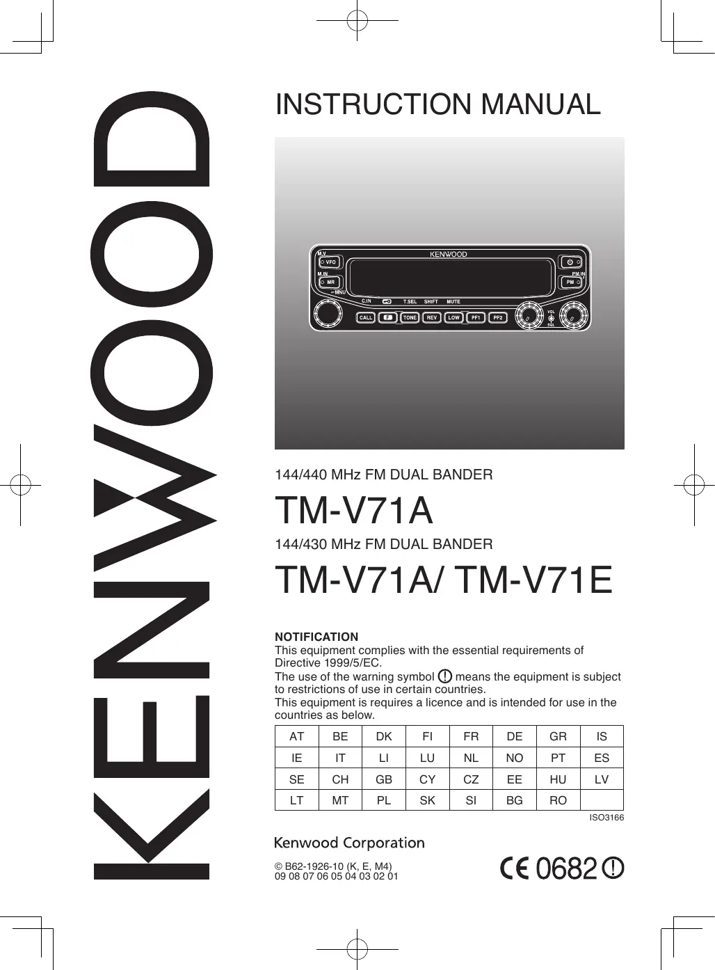
1 Install the mounting bracket in the vehicle using the supplied self-tapping screws and flat washers (4 of each are supplied).
- The bracket can be mounted with the bracket opening facing down, for underdash mounting, or facing up.
- The bracket must be installed so that the 3 screw slots on the edge of each bracket side are facing the back.
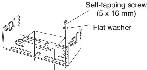
2 Position the transceiver, then insert and tighten the supplied hexagon SEMS screws and flat washers (4 of each are supplied, 2 for each side of the bracket).
- Ensure that all hardware is tightened, to prevent vehicle vibration from loosening the bracket or transceiver.
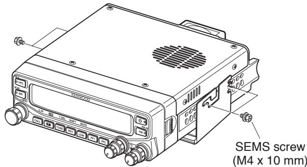
- Set an appropriate angle for the main unit, using the 3 screw slots on the rear edge of each bracket side.
natural_image
Three technical line drawings of mechanical components with no visible text or symbolsBe sure to use a 12 V vehicle battery that has sufficient current capacity. If the current to the transceiver is insufficient, the display may darken during transmission or the transmit output power may drop excessively. Never connect the transceiver to a 24 V battery
Note: If you use the transceiver for a long period when the vehicle battery is not fully charged or when the engine is OFF, the battery may become discharged and will not have sufficient reserves to start the vehicle. Avoid using the transceiver under these conditions.
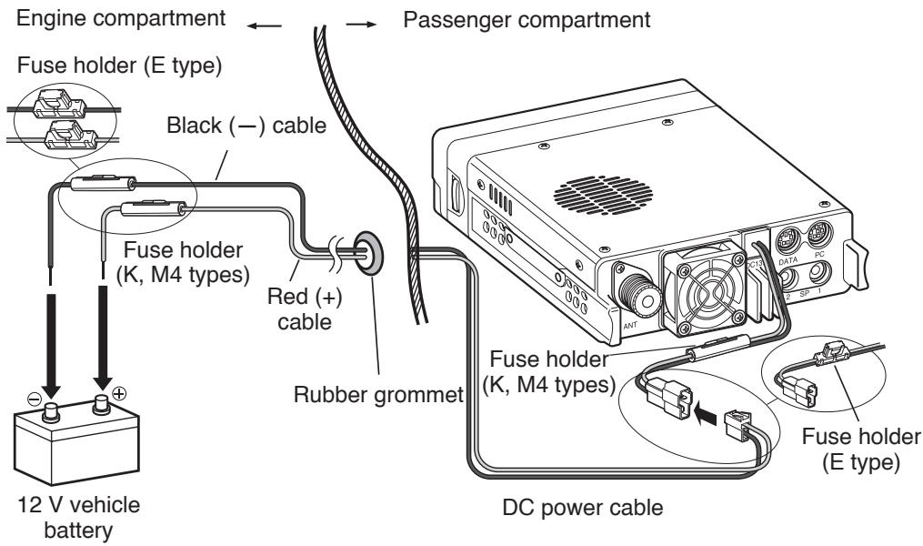
1 Route the DC power cable supplied with the transceiver directly to the vehicle's battery terminals using the shortest path from the transceiver.
- When using a noise filter, it should be installed with an insulator to prevent it from touching metal on the vehicle.
- We do not recommend using a cigarette lighter socket as some cigarette lighter sockets introduce an unacceptable voltage drop.
- If the power cable must be routed through a hole in the vehicle chassis or body, for example in the firewall at the front of the passenger compartment, use a rubber grommet to protect the cable from abrasion. Dismantle the fuse holder to pass the cable through the firewall.
- The entire length of the cable must be dressed so it is isolated from heat, moisture, and the engine secondary (high voltage) ignition system/ cables.
2 After the cable is in place, wind heat-resistant tape around the fuse holder to protect it from moisture. Tie down the full run of cable.
3 To prevent the risk of short circuits, disconnect other wiring from the negative (−) battery terminal before connecting the transceiver.
4 Confirm the correct polarity of the connections, then attach the power cable to the battery terminals; red connects to the positive (+) terminal and black connects to the negative (−) terminal.
- Use the full length of the cable without cutting off excess, even if the cable is longer than required. In particular, never remove the fuse holders from the cable.
5 Reconnect any wiring removed from the negative terminal.
6 Connect the DC power cable to the transceiver.
- Press the connectors firmly together until the locking tab clicks.
■ Fixed Station Operation
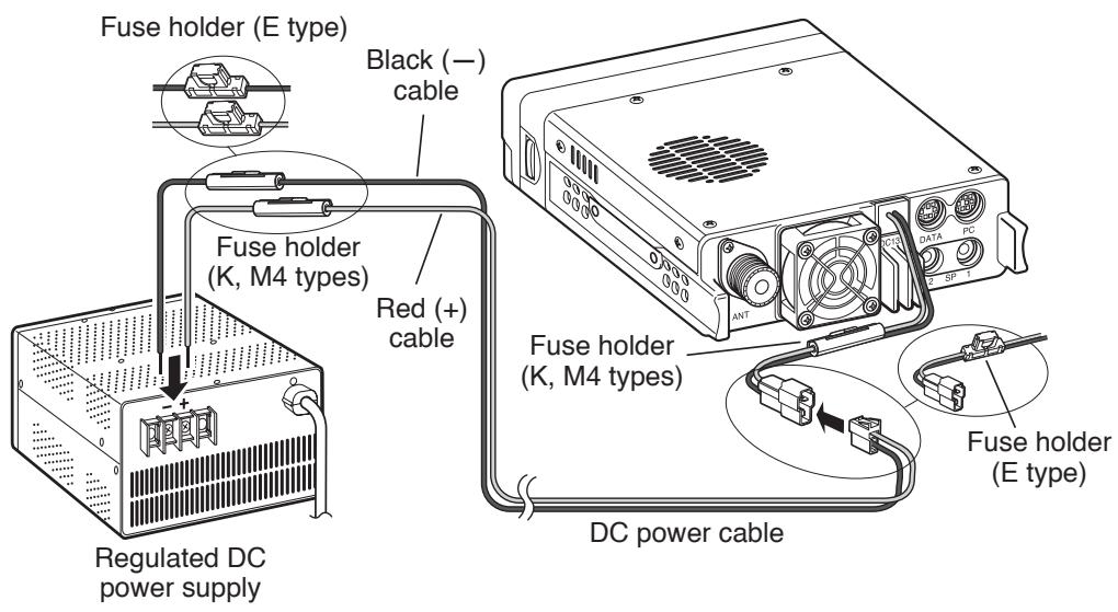
In order to use this transceiver for fixed station operation, you will need a separate 13.8 V DC power supply that must be purchased separately. The recommended current capacity of the power supply is 13 A.
Note: Do not plug the DC power supply into an AC outlet until you make all connections.
1 Ensure that the transceiver and DC power supply are both OFF. 2 Connect the DC power cable to the regulated DC power supply and ensure that the polarities are correct (Red: positive, Black: negative).
- Use the supplied DC power cable to connect the transceiver to a regulated power supply. Do not directly connect the transceiver to an AC outlet.
- Do not substitute the cable with smaller gauge wires.
3 Connect the DC power cable to the transceiver.
- Press the connectors firmly together until the locking tab clicks.
Note: For your transceiver to fully exhibit its performance capabilities, we recommend using an optional PS-33 (20.5 A, 25% duty cycle) power supply.
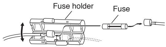
■ Replacing Fuses
If the fuse blows, determine the cause, then correct the problem. After the problem is resolved, replace the fuse. If newly installed fuses continue to blow, disconnect the power cable and contact your authorized Kenwood dealer or an authorized Kenwood service center for assistance.
| Fuse Location | Fuse Current Rating |
| Transceiver(located on the DC connector) | 15 A |
| Supplied DC power cable | 20A |

Only use fuses of the specified type and rating; otherwise the transceiver could be damaged.
Fuse holder (E type)
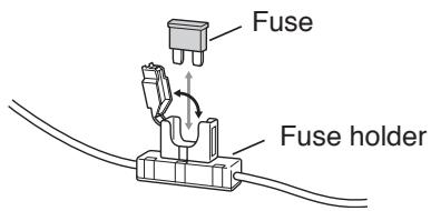
Fuse holder (K, M4 types)
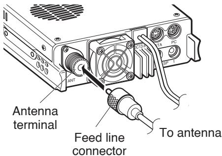
ANTENNA CONNECTION
Before operating, you must first install an efficient, well-tuned antenna. The success of your installation will depend largely on the type of antenna and its correct installation. The transceiver can give excellent results if the antenna system and its installation are given careful attention.
Use a low-loss coaxial feed line that also has a characteristic impedance of 50 , to match the transceiver input impedance. Coupling the antenna to the transceiver via feed lines having an impedance other than 50 reduces the efficiency of the antenna system and can cause interference to nearby broadcast television receivers, radio receivers, and other electronic equipment.

CAUTION
Transmitting without first connecting an antenna or other matched load may damage the transceiver. Always connect the antenna to the transceiver before transmitting.
All fixed stations should be equipped with a lightning arrester to reduce the risk of fire, electric shock, and/or transceiver damage.
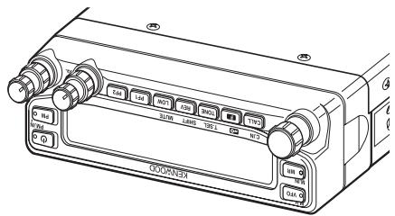
FRONT PANEL ORIENTATION
This transceiver allows you to change the orientation of the front panel. Depending on where/how you installed the transceiver you may wish to flip the front panel upside-down for easier operation.
1 On the right side of the front panel, pull the panel release latch forward.
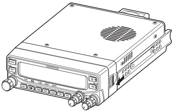
2 Slide the front panel to the left, then pull it away from the main body of the transceiver.
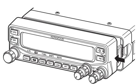
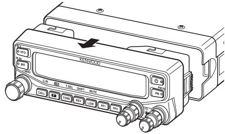
3 Flip the front panel upside-down, then reattach it to the main body of the transceiver.
ACCESSORY CONNECTIONS
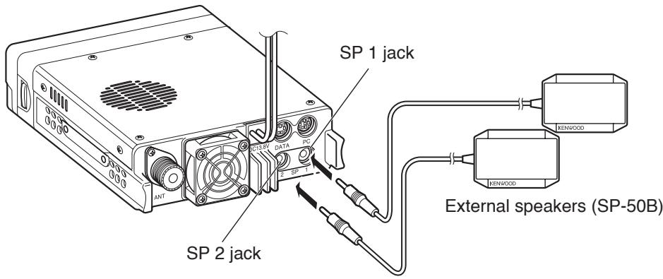
■ External Speakers
If you plan to use external speakers, choose speakers with an impedance of 8 Ω. The external speaker jacks accept a 3.5 mm (1/8") mono (2-conductor) plug. We recommend using SP-50B speakers.
There are 2 speaker jacks on the rear of the transceiver: SP 1 and SP 2. Refer to page 71 to determine how the speakers will be used.
■ Microphone
To communicate using voice, connect the supplied microphone to the MIC jack on the left side of the transceiver. Press firmly on the plug until the locking tab clicks.
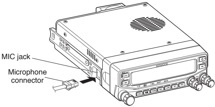
- Attach the microphone hanger to an appropriate position using the screws included in the screw set.

FRONT PANEL
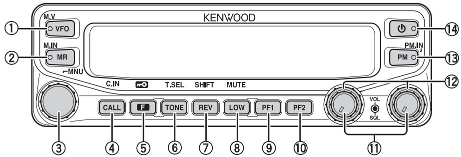
① VFO
Press [VFO] to enter VFO mode {page 18}, then rotate the Tuning control to select an operating frequency. Press [VFO] (1s) to start VFO scan {page 43}. Press F, [VFO] to copy the current Memory channel or Call channel to the VFO (memory shift) {page 36}.
② MR
Press [MR] to enter Memory Channel mode {page 18}, then rotate the Tuning control to select a Memory channel. Press [MR] (1s) to start Memory scan {page 44}. Select a Memory channel, then press F, [MR] to store the current operating frequency in the Memory channel {page 33}.
③ Tuning Control
Rotate to select an operating frequency or Memory channel, change the scan direction, select a tone frequency, etc. Press the Tuning control to enter MHz mode (while in VFO or Call mode) or to toggle the display between the channel name and frequency (while in Memory Channel mode). Press F, then press the Tuning control to enter Menu mode {page 20}. Press the Tuning control (1s) to start MHz scan {page 48} or Group scan {page 45}.
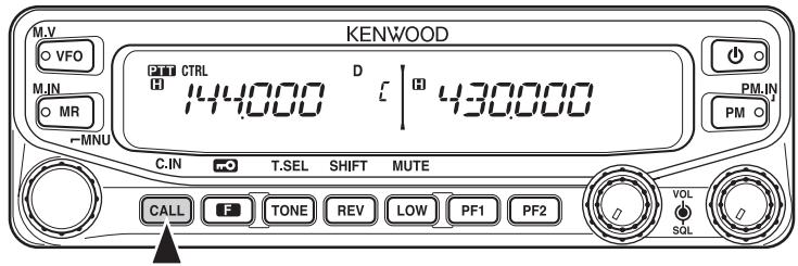
④ CALL
Press [CALL] to select the Call channel. Press [CALL] (1s) to start Call scan {page 48}. Press F, [CALL] to store the current operating frequency to the Call channel {page 33}.
⑤ F
Press F to enter Function mode. Press F (1s) to turn the transceiver key lock function ON or OFF {page 63}.
⑥ TONE
Press TONE to turn the Tone function ON. Continually press TONE to toggle the functions as follows: Tone ON >> CTCSS ON >> DCS ON >> OFF. While Tone, CTCSS, or DCS is ON, press F, TONE to enter CTCSS or DCS setup mode.
⑦ REV
Press REV to turn the Reverse function ON or OFF {page 30}. Press REV (1s) to turn the Automatic Simplex Checker ON {page 30}. Press F, REV to enter Offset Direction selection mode. Each time you press F, REV, the offset direction toggles as follows:
plus (+) direction -> minus (−) direction -> -7.6 MHz (E type only) -> OFF.
⑧ LOW
Press LOW to toggle the transmit output power as follows: High Power (K, E types only) -> Middle Power -> Low Power {page 70}. Press F, LOW to turn the Mute function ON or OFF {page 69}.
⑨ PF1
Press PF1 to activate its programmable function {page 66}. The default function is “Weather Channel” (K type)/ “Frequency Band Select” (E, M4 types).
⑩ PF2
Press [PF2] to activate its programmable function {page 66}. The default function is “Operation Band Select”.
⑪ BAND SEL (VOL) Control
Rotate the [BAND SEL] control to adjust the speaker volume {page 14}. Press the left [BAND SEL] to select the A band. Press the right [BAND SEL] to select the B band. Press [BAND SEL] (1s) to toggle between single and dual-band mode.
⑫ SQL Control
Rotate the [SQL] control to adjust the squelch level. Clockwise opens the squelch and counterclockwise tightens the squelch {page 68}.
⑬ PM
Press [PM] to enters the PM (Programmable Memory) channel selection mode {page 40}. Press F, [PM] to enter PM Channel registration mode {page 40}.
⑭
Press [∅] to turn the transceiver power ON and OFF.
< B Band >

| Indicator | Description |
| PTT | Appears when there is a transmission band available. Blinks when the cross-band repeater is ON (K type only). |
| CTRL | Appears when there is an operation band available. Blinks when the wireless remote control is ON (K type only). |
| T | Appears when the Tone function is ON. |
| CT | Appears when the CTCSS function is ON. |
| DCS | Appears when the DCS function is ON. |
| + | Appears when the Shift function is set to plus. |
| - | Appears when the Shift function is set to minus. |
| R | Appears when the Reverse function is ON. |
| R | Appears when the ASC function is ON. Blinks when the ASC function is performing an OK check. |
| AM | Appears while in AM mode. |
| N | Appears while in Narrow FM mode. |
| ▲ | Appears when the selected channel is registered while in Memory Input mode. |
| 888 | Displays the Memory channel and Menu number. |
| ★ | Appears when the Memory Channel Lockout function is ON. |
| H | Appears while using High output power. Blinks when the temperature protection circuit (transmit power save) turns on. (K, E types only) |
| M | Appears while using Middle output power. Blinks when the temperature protection circuit (transmit power save) turns on. |
| L | Appears while using Low output power. |
| 123456789 | Displays the operating frequency, Memory channel name, and Menu. |
| BUSY | Appears when receiving a busy signal. |
| 123456789 | Performs as an S meter when receiving a signal and displays the selected power level while transmitting. |
| ONAR | Appears while transmitting. |
| D | Appears while using the data band. |
| 96 | Appears when the data terminal is set as 9600 (bps). |
| 25 | Appears when the frequency is set to ***, **, 250 Hz. |
| 5 | Appears when the frequency is set to ***, **, 500 Hz. |
| 75 | Appears when the frequency is set to ***, **, 750 Hz. |
| 33 | Appears when the frequency is set to ***, **, 333 Hz. |
| 67 | Appears when the frequency is set to ***, **, 666 Hz. |
| F | Appears when the F key is pressed. |
| MUTE | Appears when mute function is ON. |
| Appears while making a continuous recording. | |
| Appears while in EchoLink Sysop mode. | |
| mO | Appears when the Key Lock function is ON. |
| OFF | Appears when making a PM channel call. |
| ESC | Appears while in Menu mode and when the Tone/CTCSS/DCS code is selected. |
| PM1◀ | Blinks when recalling a PM channel and while writing to memory. Only the “1” will blink while recording or in playback mode. |
| BACK | Appears while accessing the Menu. |
| PM2◀ | Blinks when recalling a PM channel and while writing to memory. Only the “2” will blink while recording or in playback mode. |
| ← | Appears when entering characters in Menu mode or entering a code. |
| PM3◀ | Blinks when recalling a PM channel and while writing to memory. Only the “3” will blink while recording or in playback mode |
| → | Appears when entering characters in Menu mode or entering a code. |
| PM4◀ | Blinks when recalling a PM channel and while writing to memory. Only the “4” will blink while recording or in playback mode. |
| CLR | Appears when entering characters in Menu mode or entering a code. |
| PM5◀ | Blinks when recalling a PM channel and while writing to memory. |
| WX | Appears when Weather Alert is ON. Blinks when receiving a signal. (K type only) |
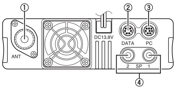
REAR PANEL
① ANT
Connect an M-type (TM-V71A) or N-type (TM-V71E) external antenna to this terminal {page 5}. When making test transmissions, connect a dummy load in place of the antenna. The antenna system or load should have an impedance of 50 Ω.
② DATA
Connect a TNC unit to this terminal, via a 6-pin mini DIN connector.
③ PC
Connect a personal computer to this terminal, via an 8-pin mini DIN connector.
④ SP (SP 1/ SP 2)
If desired, connect 1 or 2 external speakers for clearer audio. These jacks accept 3.5 mm (1/8") diameter, 2-conductor plugs {page 7}. Refer to page 71 to determine how the speakers will be used.
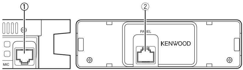
SUB-PANEL
① MIC
Connect the supplied microphone to this jack {page 7}.
② PANEL
When using an optional panel kit, attach the panel to this terminal using the
cable that comes with the panel kit.
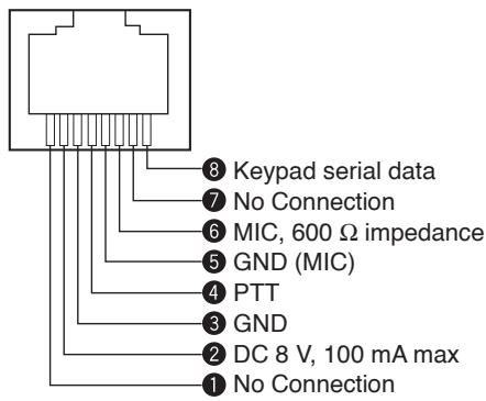
Microphone Jack
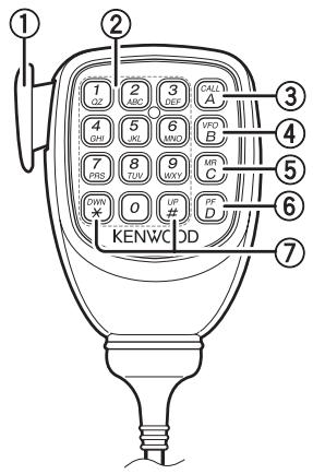
MICROPHONE (MC-59)
① PTT switch
Press and hold, then speak into the microphone to transmit.
② DTMF keypad
Press these keys to make DTMF calls, enter frequencies, or enter characters.
③ CALL/A
Functions the same as the transceiver front panel [CALL] key. This is also the PF4 key and can be reprogrammed with a programmable function {page 66}.
④ VFO/ B
Functions the same as the transceiver front panel [VFO] key. This is also the PF3 key and can be reprogrammed with a programmable function {page 66}.
⑤ MR/ C
Functions the same as the transceiver front panel [MR] key. This is also the PF2 key and can be reprogrammed with a programmable function {page 66}.
⑥ PF/D
Press to toggle between bands A and B. This is also the PF1 key and can be reprogrammed with a programmable function {page 66}.
⑦ UP/ DWN
Functions the same as the transceiver Tuning control.
SWITCHING THE POWER ON/ OFF
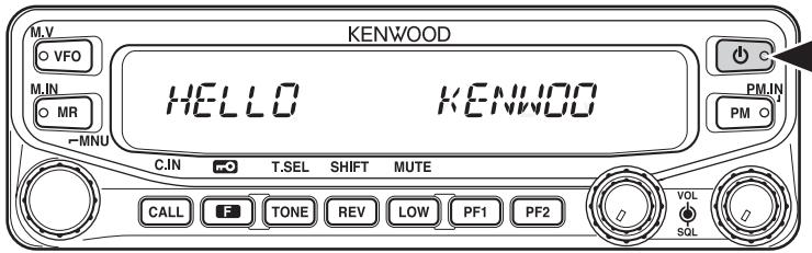
Press the [⏻] switch to switch the transceiver ON.
- The power on message momentarily appears on the display.
- If the transceiver power on password has been activated {page 74}, you must first enter your password before you can operate the transceiver.
Press the [∅] switch again to switch the transceiver OFF.
ADJUSTING THE VOLUME
Rotate the [BAND SEL] (VOL) control of your selected band clockwise to increase the volume and counterclockwise to decrease the volume.
Note: Some functions of this transceiver, such as the beep and voice announcements, have their own volume settings. Adjust those settings to your desired values.
ADJUSTING THE SQUELCH
Squelch is used to mute the speaker when no signals are present. With the squelch level set correctly, you will hear sound only while actually receiving a signal. The higher the squelch level selected, the stronger the signals must be in order to hear them.
Rotate the [SQL] control of your selected band, when no signals are present, and select the squelch level at which the background noise is just eliminated.
SELECTING A BAND
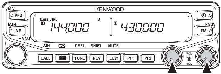
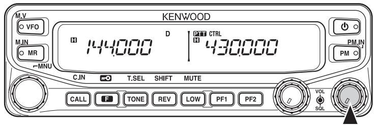
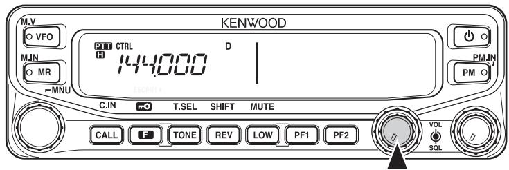
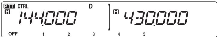
Press the left [BAND SEL] control to select band A and the right [BAND SEL] control to select band B.
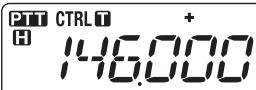
- The CTRL icon appears at the top of the band on which you are operating and the 📄️ button icon appears at the top of the band on which you are currently set to transmit.
Band A (left [BAND SEL] control):
Band B (right [BAND SEL] control):
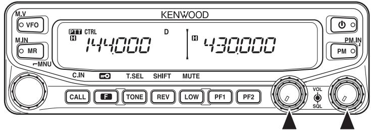
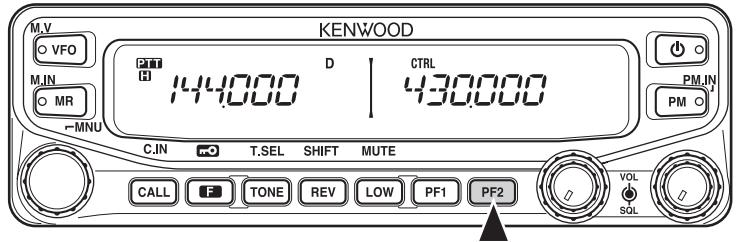
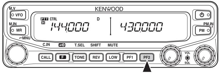
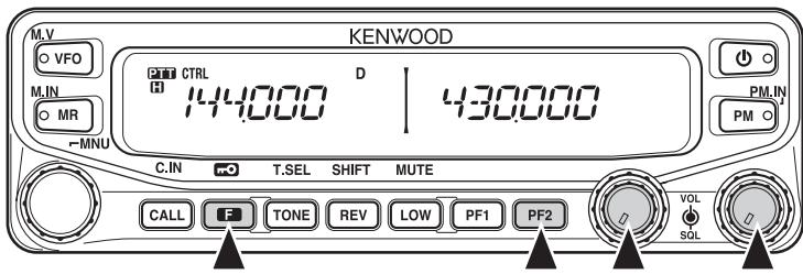
Pressing [PF2] allows you to switch the operating band between bands A and B, while maintaining the original band as the transmit band.
Band A is the transmit band and band B is the operating band:
Band A is both the transmit and operating band:
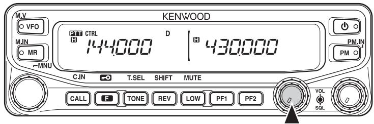
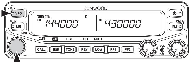
You can switch the transceiver between dual band operation and single band operation by pressing [BAND SEL] (1s) of your selected band.
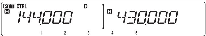
Dual band mode:
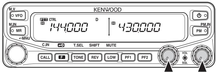
Single band mode (band A only):
Note: You can also turn the center partion bar display off {page 72}.
SELECTING A FREQUENCY BAND
You can change the default frequency bands for bands A and B.
1 Select band A or B by pressing the [BAND SEL] control or [PF2].
2 Press F, [BAND SEL] of your selected band.
• Each time you press F, [BAND SEL], you cycle to the next frequency band.
- The default setting of the PF1 key also allows you to cycle to the next frequency band (E, M4 types).
- When masking a band {page 71}, you are restricted to using only the selectable band.
- When receiving 2 signals on the same band, the image interference, sensitivity, etc., performance will decrease.
- Band A: 118 >> 144 (default) >> 220 >> 300 >> 430/440 (MHz).
- Band B: 144 >> 220 >> 300 >> 430/440 (default) >> 1200 (MHz).
Note:
◆ M4 type models do not have the following frequency bands available: 118, 220, 300, or 1200 (MHz).
◆ E and M4 type models use the 430 MHz band and K type models use the 440 MHz band.
Frequency ranges:
• 118 MHz: 118 \~ 135.995 MHz
• 144 MHz: 136 \~ 199.995 MHz
• 220 MHz: 200 \~ 299.995 MHz
• 300 MHz: 300 \~ 399.995 MHz
• 430/440 MHz: 400 \~ 523.995 MHz
• 1200 MHz: 800 \~ 1299.990 MHz (excluding cellular band)
SELECTING AN OPERATING MODE
There are 3 operating modes available to choose from: VFO mode, Memory Channel mode, and Call Channel mode.
VFO Mode
VFO mode allows you to manually change the operating frequency.
1 Press [VFO] to enter VFO mode.
2 Rotate the Tuning control to select your desired operating frequency.
- You can also adjust the frequency by using the microphone [UP]/[DWN] keys.
- The default step frequency for the Tuning control varies according to the type and operating band:
| Type | 144 MHz | 430/440 MHz |
| K | 5 kHz | 25 kHz |
| E | 12.5 kHz | 25 kHz |
| M4 | 10 kHz | 10 kHz |
- To adjust the frequency by a larger amount, you can press the Tuning control to enter MHz mode. While in MHz mode, rotate the Tuning control to adjust the frequency in steps of 1 MHz. Press the Tuning control again to exit MHz mode and adjust the frequency using the normal step frequency. Using the MCP-2A (Memory Control Program), you can set the MHz mode step frequency to 10 MHz. Pressing the Tuning control will switch between 10 MHz, 1MHz, and off.
■ Memory Channel Mode
Memory Channel mode allows you to quickly select a frequently used frequency and related data which you have saved in the transceiver memory.
1 Press [MR] to enter Memory Channel mode.
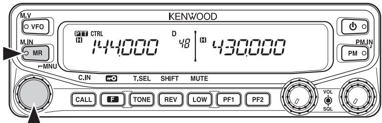
2 Rotate the Tuning control to select your desired Memory channel.
■ Call Channel Mode
Call Channel mode allows you to quickly select a preset channel to allow immediate calls on that frequency. The Call channel can be conveniently used as an emergency channel within your group.
1 Select your desired band (A or B).
- The Call channel has a dedicated frequency for both bands A and B. The default frequency for band A is 144 MHz. The default frequency for band B is 430/440 MHz.
2 Press [CALL] to enter Call Channel mode.
- “C” appears on the display.
3 Press [CALL] again to return to your previous operating frequency.
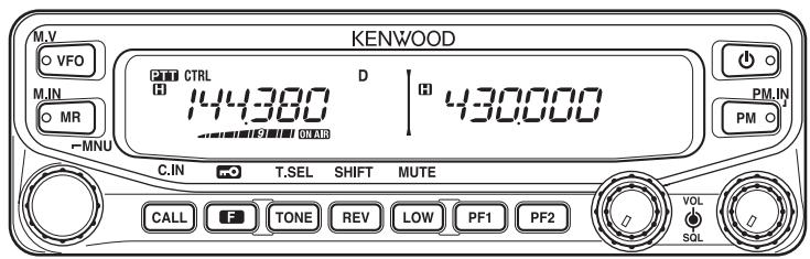
TRANSMITTING
1 Select your desired band and frequency/channel.
2 Press and hold the microphone [PTT] switch and speak into the microphone to transmit.
- The ONAIR icon and the RF power meter appear on the display for the selected transmit band. The RF power meter shows the relative transmit output power.
- The H/ M/ L icon appears on the display, depending on what output power you have selected {page 70}.
- Speak into the microphone in your normal voice, while keeping the microphone approximately 5 cm from your mouth. Speaking too close to the microphone or too loudly may increase distortion and reduce intelligibility of your signal at the receiving station.
3 When you finish speaking, release the [PTT] switch.
Many functions on this transceiver are selected or configured through the Menu instead of physical controls. Once you become familiar with the Menu system, you will appreciate the versatility it offers.
MENU ACCESS
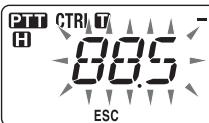
1 Press F, Tuning control to access the Menu.
- The Menu name and number appears on the display.

ESC


2 Rotate the Tuning control to select your desired Menu.
3 Press the Tuning control to set up the current Menu.

ESC


4 Rotate the Tuning control to select your desired value for the selected Menu.
5 Press the Tuning control to set the selected value.
6 Repeat steps 2 to 5 to set up additional Menus.
- Press F (ESC) at any time to exit Menu mode.
- Press TONE (BACK) at any time to cancel the Menu setup and return to the Menu selection.
MENU CONFIGURATION
| Menu No. | Display | Description | Setting Values | Default Setting | Ref. Page |
| 000 | BEEP | Beep sound | OFF/ ON | ON | 64 |
| 001 | BP.VOL | Beep volume level | 1 ~ 7 | 5 | 64 |
| 002 | EXT.SP | External speaker output mode | MODE 1/MODE 2 | MODE 1 | 71 |
| 003^1 | ANN | Voice announcement mode | OFF/ AUTO/MANUAL | AUTO | 75 |
| 004^1 | ANN.LNG | Voice announcement language | ENG/ JPN | ENG | 77 |
| 005^1 | ANN.VOL | Voice announcement volume | 1 ~ 7 | 5 | 77 |
| 006^1 | ANN.SPD | Voice announcement speed | 0 ~ 4 | 1 | 77 |
| 007^1 | PLAY.BK | Recording playback repeat | OFF/ ON | OFF | 80 |
| 008^1 | P.BK.INT | Playback repeat interval time | 0 ~ 60 (seconds) | 10 | 80 |
| 009^1 | CON.REC | Continuous recording | OFF/ ON | OFF | 79 |
| 100 | PRG.VFO | Programmable VFO setup | Varies with the selected frequency band | - | 64 |
| 101 | STEP | Step frequency | Varies with the selected frequency band | - | 65 |
| 102 | MODLAT | Modulation/demodulation mode | Varies with the selected frequency band | - | 69 |
| 103 | VHF.AIP | VHF band AIP | OFF/ ON | OFF | 68 |
| 104 | UHF.AIP | UHF band AIP | OFF/ ON | OFF | 68 |
| 105 | S.SQL | S-meter squelch | OFF/ ON | OFF | 68 |
| 106 | S.SQ.HNG | S-meter squelch hangup time | OFF/ 125/ 250/ 500 (ms) | OFF | 68 |
| 107 | MUT.HNG | Mute hangup time setup | OFF/ 125/ 250/ 500/ 750/ 1000 (ms) | OFF | 70 |
| 108 | B.SHIFT | Beat shift | OFF/ ON | OFF | 69 |
| 109 | TOT | Time-out timer | 3/ 5/ 10 (minutes) | 10 | 70 |
| 110^2 | WX.ALT | Weather alert | OFF/ ON | OFF | 73 |
| 200^3 | M.NAME | Memory name setup | Up to 6 characters | - | 35 |
| 201 | RECALL | Memory channel recall method | ALL/ CURRENT | ALL | 34 |
| 202^3 | L.OUT | Memory channel lockout | OFF/ ON | OFF | 44 |
| 203 | GR.LINK | Memory group link registration | Up to 10 digits (0 ~ 9) | - | 45 |
| 204 | ELK.MEM | EchoLink memory setting | Up to 8 digits for DTMF code | - | 59 |
| 205 | ELK.SPD | EchoLink memory transmission speed | FAST/ SLOW | FAST | 60 |
| 300 | DT.HOLD | DTMF transmission hold | OFF/ ON | OFF | 55 |
| 301 | DT.MEM | DTMF memory | Up to 16 cdigits for DTMF code | - | 56 |
| 302 | DT.SPD | DTMF memory transmission speed | FAST/ SLOW | FAST | 57 |
| 303 | DT.PAUS | DTMF pause code time | 100/ 250/ 500/ 750/ 1000/ 1500/ 2000 (ms) | 500 | 58 |
| 304 | DT.LOCK | DTMF key lock | OFF/ ON | OFF | 58 |
| 400 | OFFSET | Offset frequency | See reference page | - | 27 |
| 401^4 | ARO | Auto Repeater Offset | OFF/ ON | ON | 29 |
| 402 | 1750.HD | Transmission hold when transmitting a 1750 Hz tone | OFF/ ON | OFF | 30 |
| 403^2 | RPT.MOD | Repeater mode | CROSS/ A-TX/ B-TX | CROSS | 81 |
| 404^2 | RPT.HLD | Repeater transmission hold | ON/ OFF | OFF | 82 |
| 405^2 | RPT.ID | Repeater ID registration | Up to 6 characters | - | 82 |
| 406^2 | ID.TX | Repeater ID transmission | OFF/ MORSE/ VOICE | OFF | 82 |
| 500 | P.ON.MSG | Power on message setup | Up to 6 characters | HELLO | 62 |
| 501 | BRIGHT | Display brightness | OFF/ 1 ~ 8 | 8 | 62 |
| 502 | AUTO.BR | Display auto brightness | OFF/ ON | OFF | 62 |
| 503 | COLOR | Backlight color | AMBER/ GREEN | AMBER | 63 |
| 507 | PF1 | PF1 key programmable function value | See reference page | FR.BAND | 66 |
| 508 | PF2 | PF2 key programmable function value | See reference page | CTRL | 66 |
| 509 | MIC.PF1 | Microphone PF1 key programmable function value | See reference page | A/B | 66 |
| 510 | MIC.PF2 | Microphone PF2 key programmable function value | See reference page | MR | 66 |
| 511 | MIC.PF3 | Microphone PF3 key programmable function value | See reference page | VFO | 66 |
| 512 | MIC.PF4 | Microphone PF4 key programmable function value | See reference page | CALL (K/ M4 types) 1750 (E types) | 66 |
| 513 | MIC.LCK | Microphone key lock | OFF/ ON | OFF | 63 |
| 514 | SC.RESM | Scan resume method | TO/ CO/ SEEK | TO | 43 |
| 516 | APO | Auto Power Off time | OFF/ 30/ 60/90/ 120/ 180(minutes) | OFF | 67 |
| 517 | DAT.BND | Data Band mode | A/ B/ ATX.BRX/ARX.BTX | A | 83 |
| 518 | DAT.SPD | Data communications speed | 1200/ 9600 (bps) | 1200 | 83 |
| 519 | PC .SPD | PC terminal baud rate speed | 9600/ 19200/38400/ 57600(bps) | 9600 | 84 |
| 520 | SQC.SRC | SQC output type | OFF/ BUSY/SQL/ TX/BUSY.TX/SQL.TX | BUSY.TX | 84 |
| 521 | AUTO.PM | Automatic PM entry | OFF/ ON | ON | 41 |
| 522^2 | REM.ID | Personal Identificaton Number | 000 ~ 999 | 000 | 85 |
| 523^2 | ANS.BK | Answer back | OFF/ ON | ON | 85 |
| 527 | DP.BAR | Display partition bar | OFF/ ON | ON | 72 |
| 998 | PASSWD | Power on password | OFF/ ON | OFF | 74 |
| 999 | RESET | Reset | VFO/ PART/ PM/FULL | VFO | 88 |
^1 Menu numbers 03 \~ 09 are available only when the optional VGS-1 unit is installed in the transceiver.
^2 Menu numbers 110, 403 \~ 406, 522, and 523 are available only for K type models.
^3 Menu numbers 200 and 202 are available only if a Memory Channel has been stored in the transceiver.
^4 Menu number 401 is available only for K and E type models.
CHARACTER ENTRY
Certain menus require you to enter characters, such as the power on message and memory names. When character entry is required, a cursor will appear on the display.
1 Press the Tuning control.
• The cursor will blink.
2 Rotate the Tuning control to select your desired character.
- You can enter characters as described below:
- Power on message, memory name, and repeater ID (K type only): 0 \~ 9, A \~ Z, -, /, @, and space
- DTMF memory code: 0 \~ 9, A \~ F, and space
- EchoLink memory code: 0 \~ 9, A \~ F
- Memory group link and wireless remote ID (K type only): 0 \~ 9
3 Press the Tuning control to set the selected character.
• The cursor will move to the next digit.

- You can move the cursor to the left or right by pressing REV (←) or LOW (→).
- You can delete the selected character by pressing PF1 (CLR).
4 Repeat steps 2 and 3 to enter the remaining characters.
- Press F (ESC) at any time to exit Menu mode.
- Press TONE (BACK) at any time to cancel the Menu setup and return to the Menu selection.
■ Microphone Keypad Character Entry
The microphone keys can also be used to enter characters. Refer to the table below for characters corresponding to microphone keys.
| Key | Character Display (with each press of the key) | |||
| 1 | Q | Z | 1 | |
| 2 | A | B | C | 2 |
| 3 | D | E | F | 3 |
| 4 | G | H | I | 4 |
| 5 | J | K | L | 5 |
| 6 | M | N | O | 6 |
| 7 | P | R | S | 7 |
| 8 | T | U | V | 8 |
| 9 | W | X | Y | 9 |
| 0 | (space) | 0 | ||
| * | Not used | |||
| # | - | / | @ | |
The microphone [A] \~ [D] keys have special functions assigned to them:
[A]: Functions the same as PF1 (CLR)
[B]: Functions the same as REV ( )
[C]: Functions the same as LOW ( )
[D]: Functions the same as the Tuning control
Repeaters are often installed and maintained by radio clubs, sometimes with the cooperation of local businesses involved in the communications industry.
Compared to simplex communication, you can usually transmit over much greater distances by using a repeater. Repeaters are typically located on mountain tops or other elevated locations. They generally operate at higher ERP (Effective Radiated Power) than a typical station. This combination of elevation and high ERP allows communications over considerable distances.
TX: 144.725 MHz TX tone: 88.5 Hz RX: 145.325 MHz
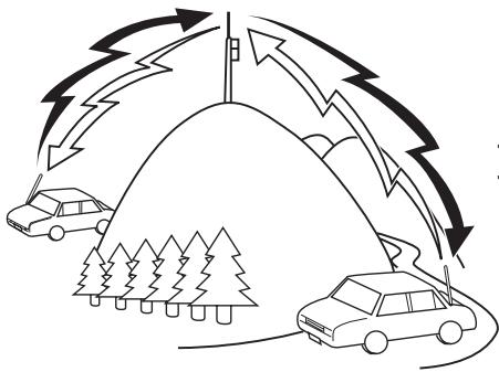
natural_image
Diagram showing cars approaching a road with lightning bolts and trees, no text or symbols presentTX: 144.725 MHz
TX tone: 88.5 Hz
RX: 145.325 MHz
REPEATER ACCESS
Most repeaters use a receive and transmit frequency pair with a standard or non-standard offset (odd-split). In addition, some repeaters must receive a tone from the transceiver in order to gain access to the repeater. For details, consult your local repeater reference.
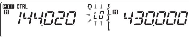
■ Selecting an Offset Direction
The offset direction allows your transmit frequency to be higher (+) or lower (−) than the receive frequency.
1 Select your desired band (A or B).
2 Press F, REV to select an offset direction.
- Each time you press F, REV, the offset direction changes as follows: Simplex operation >> + >> - >> Simplex operation
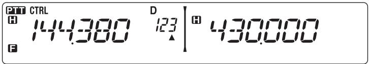
D
$$ \left| ^ {8} 4 3 0. 0 0 0 \right. $$

D
$$ \left| ^ {\text {H}} 4 3 0. 0 0 0 \right. $$
- If you are using an E type transceiver, when operating on the 430 MHz band, the offset direction changes as follows:
Simplex operation >> + >> - >> = (-7.6 MHz) >> Simplex operation
If the offset transmit frequency falls outside the allowable range, transmitting is inhibited. Use one of the following methods to bring the transmit frequency within the band limits:
- Move the receive frequency further inside the band.
- Change the offset direction.
Note: While using an odd-split memory channel or transmitting, you cannot change the offset direction.
■ Selecting an Offset Frequency
The offset frequency is the value which the transmit frequency will be offset from the receive frequency. The default offset frequency on the 144 MHz band is 600 kHz for all type versions. The default on the 430/440 MHz band is 5 MHz.
1 Select your desired band (A or B).
2 Enter Menu mode and access Menu 400 (OFFSET) {page 20}.


3 Set the appropriate offset frequency value.
- The selectable range is from 00.00 MHz to 29.95 MHz, in steps of 50 kHz.
Note: After changing the offset frequency, the new offset frequency will also be used by Automatic Repeater Offset {page 29}.
■ Activating the Tone Function
To turn the Tone function on:
1 Select your desired band (A or B).
2 Press TONE to turn the Tone function ON.
• Each time you press TONE, the selection changes as follows:
None >> T (Tone) >> CT (CTCSS) >> DCS (DCS) >> None
- The icon appears on the display when the tone function is ON.

Note: When accessing a repeater that requires a 1750 Hz tone, you do not need to activate the Tone function. Simply press the key assigned to the 1750 Hz tone {page 66} to transmit the tone.
■ Selecting a Tone Frequency
To select the tone frequency required to access your desired repeater:
1 Turn the Tone function ON.
2 Press F, TONE.
- The current tone frequency appears on the display. The default frequency is 88.5 Hz.


3 Rotate the Tuning control to select your desired frequency.
• To exit the tone frequency selection, press F (ESC).
4 Press any key other than the Tuning control and F (ESC) to set the selected frequency.
Note: If you have set up a Memory channel with a tone setting, simply recall the Memory channel instead of setting up the tone frequency every time.
| No. | Frequency (Hz) | No. | Frequency (Hz) | No. | Frequency (Hz) | No. | Frequency (Hz) |
| 01 | 67.0 | 12 | 97.4 | 23 | 141.3 | 34 | 206.5 |
| 02 | 69.3 | 13 | 100.0 | 24 | 146.2 | 35 | 210.7 |
| 03 | 71.9 | 14 | 103.5 | 25 | 151.4 | 36 | 218.1 |
| 04 | 74.4 | 15 | 107.2 | 26 | 156.7 | 37 | 225.7 |
| 05 | 77.0 | 16 | 110.9 | 27 | 162.2 | 38 | 229.1 |
| 06 | 79.7 | 17 | 114.8 | 28 | 167.9 | 39 | 233.6 |
| 07 | 82.5 | 18 | 118.8 | 29 | 173.8 | 40 | 241.8 |
| 08 | 85.4 | 19 | 123.0 | 30 | 179.9 | 41 | 250.3 |
| 09 | 88.5 | 20 | 127.3 | 31 | 186.2 | 42 | 254.1 |
| 10 | 91.5 | 21 | 131.8 | 32 | 192.8 | ||
| 11 | 94.8 | 22 | 136.5 | 33 | 203.5 |
■ Automatic Repeater Offset (K and E Types Only)
This function automatically selects an offset direction and activates the Tone function, according to the frequency that you have selected. To obtain an up-to-date band plan for repeater offset direction, contact your national Amateur Radio association.
1 Enter Menu mode and access Menu 401 (ARO) {page 20}.
2 Set the ARO to ON.

ESC

BACK

3 Press [BAND SEL A] to select the A band.
4 Press [VFO] to select VFO mode.
5 Rotate the Tuning control to select your desired frequency.

H


6 Press [PTT] to start a call.
- You will be transmitting on an offset frequency value determined from your offset setting value {page 27} and an offset direction depending on your selected frequency. Refer to the settings below for offset directions:
K Type:
Under 145.100 MHz: No offset (Simplex operation)
145.100 \~ 145.499 MHz: Minus (−) offset
145.500 \~ 145.999 MHz: No offset (Simplex operation)
146.000 \~ 146.399 MHz: Plus (+) offset
146.400 \~ 146.599 MHz: No offset (Simplex operation)
146.600 \~ 146.999 MHz: Minus (−) offset
147.000 \~ 147.399 MHz: Plus (+) offset
147.400 \~ 147.599 MHz: No offset (Simplex operation)
147.600 \~ 147.999 MHz: Minus (−) offset
148.000 MHz and higher: No offset (Simplex operation)
E Type:
Under 145.000 MHz: No offset (Simplex operation)
145.600 \~ 145.799 MHz: Minus (−) offset
145.800 MHz and higher: No offset (Simplex operation)
TRANSMITTING A 1750 Hz TONE
Most repeaters in Europe require that a transceiver transmit a 1750 Hz tone. On a E type model, simply pressing Microphone [CALL] causes it to transmit a 1750 Hz tone. It is also possible to program [1750] on the front panel as a PF key for transmitting a 1750 Hz tone.
Note: The transceiver continuously transmits a 1750 Hz tone until you release Microphone [CALL] or PF key(1750).
Some repeaters in Europe must receive continuous signals for a certain period of time, following a 1750 Hz tone. This transceiver is also capable of remaining in the transmit mode for 2 seconds after transmitting a 1750 Hz tone.
1 Enter Menu mode and access Menu 402 (1750.HD) {page 20}.

ESC

2 Set the tone to ON or OFF.
- When set to ON, the 1750 Hz tone will transmit. When set to OFF, the tone will not be transmitted.
REVERSE FUNCTION
After setting a separate receive and transmit frequency, you can exchange these frequencies using the Reverse function. This allows you to manually check the strength of signals you receive directly from other stations, while using a repeater. If the station's signal is strong, move to a simplex frequency to continue the contact and free up the repeater.
Press REV to turn the Reverse function ON or OFF.
- When the Reverse function is ON, the R icon will appear on the display.

Note:
If the transmit frequency is outside the allowable transmit frequency range when using Reverse, pressing [PTT] will cause an error tone to sound and transmission will be inhibited.
If the receive frequency is outside the receive frequency range when using Reverse, an error tone will sound and Reverse will not operate.
◆ The ARO (Automatic Repeater Offset) will not function when Reverse is ON.
◆ You cannot switch Reverse ON or OFF while transmitting.
AUTOMATIC SIMPLEX CHECKER (ASC)
While using a repeater, ASC periodically monitors the strength of signals you receive directly from the other stations. If the station's signal is strong enough to allow direct contact without a repeater, the icon blinks.
Press REV (1s) to turn the ASC ON.
- When the ASC is ON, the R icon will appear on the display.

- While direct contact is possible, without the use of a repeater, the R icon will begin blinking.
• To exit ASC, press REV.
Note:
◆ Pressing [PTT] will cause the R icon to stop blinking.
◆ ASC does not function if you are using simplex operation.
◆ ASC does not function while scanning.
◆ Activating ASC while using Reverse will switch the Reverse function OFF.
If you recall a Memory channel or the Call channel, and those channels are set up with the Reverse function switched ON, the ASC will switch OFF.
ASC causes received signals to be momentarily intermitted every 3 seconds.
TONE FREQUENCY ID
This function scans through all tone frequencies to identify the incoming tone frequency on a received signal. You can use this function to find which tone frequency is required by your local repeater.
1 Press TONE to switch the Tone function ON.
• The 📊 icon appears on the display.
2 Press F, TONE (1s) to run the Tone Frequency ID scan.
- The icon blinks and SCAN appears on the display.

- To reverse the scan direction, turn the Tuning control clockwise (upward scan) or counterclockwise (downward scan).
• To quit the function, press F (ESC). - When the tone frequency is identified, the identified frequency appears on the display and blinks. Press any key other than the Tuning control while the identified frequency is blinking, to resume scanning.


3 Press the Tuning control to program the identified frequency in place of the currently set tone frequency.
- The Tone function will remain ON. You can press TONE to switch the Tone function OFF.
- Press F (ESC) if you do not want to program the identified frequency.
In Memory channels, you can store frequencies and related data that you often use. Then you need not reprogram the data every time. You can quickly recall a programmed channel by simple operation. A total of 1000 Memory channels are available for bands A and B.
SIMPLEX & REPEATER OR ODD-SPLIT MEMORY CHANNEL?
You can use each memory channel as a simplex & repeater channel or as an odd-split channel. Store only one frequency to use as a simplex & repeater channel or two separate frequencies to use as an odd-split channel. Select either application for each channel depending on the operations you have in mind.
Simplex & repeater channels allow:
- Simplex frequency operation
- Repeater operation with a standard offset (if an offset direction is stored)
Odd-split channels allow:
• Repeater operation with a non-standard offset
The data listed below can be stored in each Memory channel:
| Parameter | Simplex & Repeater | Odd-split |
| Receive frequency | Yes | Yes |
| Transmit frequency | Yes | |
| Receive frequency step size | Yes | Yes |
| Transmit frequency step size | Yes | |
| Offset direction | Yes | No |
| Tone ON/OFF | Yes | Yes |
| Tone frequency | Yes | Yes |
| CTCSS ON/OFF | Yes | Yes |
| CTCSS frequency | Yes | Yes |
| DCS ON/OFF | Yes | Yes |
| DCS code | Yes | Yes |
| Reverse ON/OFF | Yes | No |
| Memory channel lockout | Yes | Yes |
| Memory channel name | Yes | Yes |
| Modulation/Demodulation mode | Yes | Yes |
STORING SIMPLEX AND STANDARD REPEATER FREQUENCIES
1 Press [VFO] to enter VFO mode.
2 Rotate the Tuning control to select your desired frequency.
- Additionally, you can press the microphone [UP]/[DWN] keys to select a frequency.
3 Set up any additional data desired for the frequency.
- Offset direction, Tone ON/OFF, Tone frequency, CTCSS ON/OFF, CTCSS frequency, DCS ON/OFF, DCS code, etc.
4 Press F.
• A memory channel number appears.

5 Rotate the Tuning control to select your desired channel number.
- Additionally, you can press the microphone [UP]/[DWN] keys to select a channel.
6 Press [MR] to store the data in the selected Memory channel.
Note: If you store the data in a Memory channel that already has data stored in it, the old data will be cleared and the new data will be stored.
■ Call Channel Memory (Simplex)
The Call channel can be used to store any frequency and related data that you will recall often. You may want to dedicate the Call channel as an emergency channel within your group.
To store a simplex frequency and related data as the Call channel instead of in a Memory channel, after step 4 (above), press [CALL].
Note: Storing new data in the Call channel will clear the old data. (The Call channel itself cannot be cleared, but data can be replaced with new data.)
STORING ODD-SPLIT REPEATER FREQUENCIES
Some repeaters use a receive and transmit frequency pair with a non-standard offset. To access those repeaters, store two separate frequencies in a memory channel. You can then operate on those repeaters without changing the offset frequency you stored in the menu.
1 Set up a simplex channel by following steps 1 to 6 of "STORING SIMPLEX AND STANDARD REPEATER FREQUENCIES", above.
2 Press [VFO] to enter VFO mode.
3 Rotate the Tuning control to select your desired transmit frequency.
- Additionally, you can press the microphone [UP]/[DWN] keys to select a frequency.
4 Set up any additional data desired for the transmit frequency.
- Tone ON/OFF, Tone frequency, CTCSS ON/OFF, CTCSS frequency, DCS ON/OFF, DCS code, etc.
5 Press F.
• A memory channel number appears.
6 Rotate the Tuning control to select your desired channel number.
• Additionally, you can press the microphone [UP]/[DWN] keys to select a channel.

7 Press [PTT], [MR] to store the data in the selected Memory channel.
■ Call Channel Memory (Odd-Split)
The Call channel can be used to store any frequency and related data that you will recall often. You may want to dedicate the Call channel as an emergency channel within your group.
To store an odd-split frequency and related data as the Call channel instead of in a Memory channel, after step 6 (above), press [PTT], [CALL].
Note: You cannot store the transmit offset status and Reverse status in an odd-split Call channel.
RECALLING A MEMORY CHANNEL
1 Press [MR] to enter Memory Recall mode.
2 Rotate the Tuning control to select your desired Memory channel.
- Additionally, you can press the microphone [UP]/[DWN] keys to select a channel, or you can enter a channel number using the microphone keypad.
■ Memory Recall Method
The transceiver Menu also provides you with the option to recall Memory channels with stored frequencies in your current band, or all Memory channels:
1 Enter Menu mode and access Menu 201 (RECALL) {page 20}.

ESC
201

2 Set the recall method to CURRENT (current band) or ALL (all bands).
- CURRENT allows you to recall only those memory channels that have stored frequencies within the current band {page 17}. ALL allows you to recall all programmed memory channels.
- When the recalled memory channel is an AM channel, you cannot recall on the B band.
CLEARING A MEMORY CHANNEL
1 Press [MR] to enter Memory Recall mode.
2 Rotate the Tuning control to select your desired Memory channel.
- Additionally, you can press the microphone [UP]/[DWN] keys to select a channel, or you can enter a channel number using the microphone keypad.

3 Turn the transceiver power OFF.
4 Press [MR] + Power ON.
• A confirmation message appears on the display.

ESC

5 Press the Tuning control to clear the Memory channel.
• To exit without clearing the channel, press F (ESC).
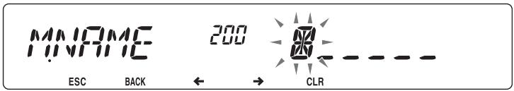
NAMING A MEMORY CHANNEL
You can name Memory channels using up to 6 alphanumeric characters. When you recall a named Memory channel, its name appears on the display instead of the stored frequency. Names can be call signs, repeater names, cities, people, etc.
1 Press [MR] to enter Memory Recall mode.
2 Rotate the Tuning control to select your desired Memory channel.
3 Enter Menu mode and access Menu 200 (M.NAME) {page 20}.

ESC

←

CLR
4 Enter your desired name for the channel {page 24}.
Note: You can overwrite a Memory channel name by performing the steps above. You can also clear a Memory channel name by clearing the Memory channel.
SWITCHING THE MEMORY NAME/ FREQUENCY DISPLAY
After storing memory names, you can switch the display between the memory name and the stored frequency. This can be useful if you need to confirm the frequency stored in named Memory channels.
1 Press [MR] to enter Memory Recall mode.
2 Press the Tuning control to toggle between the memory name and the stored frequency.

MEMORY-TO-VFO TRANSFER
Transferring the contents of a Memory channel or the Call channel to the VFO can be useful if you want to search for other stations or a clear frequency, near the selected Memory channel or Call channel frequency.
1 Press [MR] or [CALL] to enter Memory Recall mode or select the Call channel.
2 Rotate the Tuning control to select your desired channel. (This step is not necessary when selecting the Call channel.)
3 Press F, [VFO].
- The entire contents of the Memory channel or Call channel are copied to the VFO, and VFO mode is selected after the transfer is complete.
- When copying a transmit frequency from an odd-split Memory or Call channel, you must first turn the Reverse function ON before pressing F, [VFO].
CHANNEL DISPLAY FUNCTION
Use this function when you want to use only Memory channels. When this function is switched ON, the transceiver displays only a Memory channel number instead of a frequency.
1 Turn the transceiver power OFF.
2 Press LOW + Power ON to turn the channel display ON or OFF.

Note:
◆ If no Memory channels have saved data in them, channel display will not function.
If a channel has a stored name, the name will appear on the display in place of the channel number.
◆ When using Channel Display, you cannot reset the transceiver.
While in Channel Display mode, the transceiver keys function as shown below:
| Key Name | [KEY] | [F], [KEY] | [KEY] (1s) | While Transmitting | [KEY] + Power ON |
| ∅ | Power ON/OFF | Power ON/OFF | Power ON/OFF | Power ON/OFF | X |
| PM | - | - | - | - | - |
| VFO | - | - | - | - | - |
| MR | MR mode | - | Memory Scan | - | - |
| CALL | Call mode | Store in Call channel | Call Scan | - | - |
| F | Function mode | Exit Function mode | Key Lock | - | - |
| TONE | - | - | - | - | - |
| REV | Reverse ON/OFF | - | - | - | - |
| LOW | Change output power | Mute | - | Change output power | Change channel display |
| PF1 | Select the Weather channel (K type) | - | - | - | - |
| PF2 | Change control band | - | - | - | - |
| Tuning control | Change between the CH number and the channel name | - | Group Scan | - | - |
| BAND SEL A | A band | - | Change Single/Dual | - | - |
| BAND SEL B | B band | - | Change Single/Dual | - | - |
Programmable Memory (PM) stores virtually all settings currently set on the transceiver. This transceiver provides 5 PM channels to store 5 sets of transceiver configurations. Later, you can quickly recall any one of these channels, depending on the operations you have in mind or the operating environment.
The following programmable settings cannot be stored:
- Memory name
• Memory channel lockout - Channel Display mode
- Locked-band/ Cross-band Repeater ON/OFF ^1
- Repeater mode ^1
- Repeater hold ^1
- Repeater ID transmit ^1
- Registered repeater ID ^1
- Wireless remote control ^1
- Answer back ^1
- Remote control ID ^1
- Key lock
- Power on password ^2
- Memory channel/ Call channel/ Program scan memory
- Weather channel ^1
- DTMF memory
- EchoLink memory
- PC port speed
- 10 MHz mode ^2
- Mic sensitivity ^2
- SQC data output logic ^2
^1 K type only ^2 Can be set only by using the MCP-2A software.
APPLICATION EXAMPLES
The following are examples of how you might use Programmable Memory. These examples may not represent applications useful to you, but you will understand the flexibility of this function.
Situation: You share your transceiver with other members in your family or club. However, each individual has personal preferences for how they like to set various functions. You have to keep changing many settings each time you use the transceiver.
Solution: Because 5 PM channels are available, up to 5 persons can separately program the transceiver and store their customized environment. Then each person can quickly change to his or her favorite settings, simply by recalling a PM channel. It is too much trouble to change back the settings after somebody else has reconfigured them. So this application may avoid having a feature-rich transceiver but never using many useful features.
Situation: While operating mobile on the way to work every morning, you prefer a silent transceiver that does not interrupt the morning calm. In addition, you feel that a bright display is useless in the sunlight. At night when driving home, you realize the Beep function truly does serve a purpose and you acknowledge it is nice to see a bright display after dark.
Solution: In 2 PM channels, store the same operating data such as frequency, offset, tone, etcl, and store different settings for the Display brightness and Beep functions. Then you can quickly recall the best settings for day or night operation.
Situation: You cannot figure out how to exit the current transceiver mode.
Solution: Simply recall PM channel 1, which contains an exact copy of the transceiver default environment. You will not lose the contents of any memory channels.
STORING DATA IN PM CHANNELS
1 Confirm that the following conditions have been satisfied:
• The transceiver is in receive mode.
- Scan is not being used.
• Microphone Control is OFF.
2 Configure the transceiver with your desired settings.
3 Press F, [PM].
- PM channel numbers 1 to 5 appear and blink at the bottom of the display.
4 Enter a channel number ([1] to [5]) corresponding to your desired PM channel.
- The settings are stored in the PM channel.
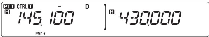
RECALLING PM CHANNELS
1 Press [PM].
- PM channel numbers 1 to 5 and OFF appear on the bottom of the display.
2 Enter a channel number ([1] to [5]) corresponding to your desired PM channel.
- The settings stored in the PM channel are recalled.
- The selected channel number appears on the display.
- When selecting [OFF], the PM channels turn off.
AUTO PM CHANNEL STORE
After you recall a PM channel, this function automatically overwrites the current PM channel with the present operating environment when:
- You recall another PM channel.
- You press [PM].
- You switch the transceiver power OFF.
Follow the steps below to activate the Auto PM storage function.
1 Enter Menu mode and access Menu 521 (AUTO.PM) {page 20}.

ESC

2 Set AUTO.PM to ON.
Note: If you do not recall a PM channel (1 - 5), Menu No. 521 will not appear on the display.
PM CHANNEL RESET
To reset the PM channels to their default settings:
1 Turn the transceiver power OFF.
2 Press F + Power ON.
3 Release F.
4 Rotate the Tuning control and select PM.

ESC

5 Press the Tuning control.
• A confirmation message appears on the display.

ESC

6 Press the Tuning control again to reset the PM channels.
- Press TONE (BACK) to return to the previous display.
• To exit without resetting the PM channels, press F (ESC).
Scan is a useful feature for hands-off monitoring of your favorite frequencies. Becoming comfortable with all types of Scan will increase your operating efficiency.
This transceiver provides the following types of scans:
| Scan Type | Scan Range |
| VFO Scan | Scans all frequencies on the current band. |
| Memory Scan | Scans all frequencies stored in the Memory channels. |
| Group Scan | Scans the frequencies in the Memory channels which belong to the group you have specified. |
| Program Scan | Scans all frequencies within the programmed range, on the current band. |
| MHz Scan | Scans all frequencies within a 1 MHz range from the originating frequency. |
| Call Scan | Scans the Call channel as well as the currently selected VFO frequency or Memory channel. |
Note:
Adjust the squelch level before using Scan. Selecting a squelch level too low could cause Scan to stop immediately.
While using CTCSS or DCS, Scan stops for any signal received; however, you will hear audio only when the signal contains the same CTCSS tone or DCS code that you selected.
When using S-meter Squelch, Scan stops when the received signal strength matches or exceeds the S-meter setting. Scan resumes 2 seconds after the signal level drops below the S-meter setting.
◆ Pressing and holding [PTT] causes Scan to temporarily stop if it is functioning on a non TX band.
◆ Starting Scan switches the Automatic Simplex Checker OFF.
SELECTING A SCAN RESUME METHOD
The transceiver stops scanning at a frequency or Memory channel on which a signal is detected. It then continues scanning according to which resume mode you have selected. You can choose one of the following modes. The default is Time-operated mode.
• Time-Operated mode
The transceiver remains on a busy frequency or Memory channel for approximately 5 seconds, and then continues to scan even if the signal is still present.
• Carrier-Operated mode
The transceiver remains on a busy frequency or Memory channel until the signal drops out. There is a 2 second delay between signal drop-out and scan resumption.
- Seek mode
The transceiver remains on a busy frequency or Memory channel even after the signal drops out and does not automatically resume scanning.
Note: To temporarily stop scanning and monitor weak signals, press the microphone PF key assigned to the Monitor function {page 66}. Press the PF key again to resume scanning.
1 Enter Menu mode and access Menu 514 (SC.RESM) {page 20}.

ESC

2 Set the Scan Resume mode to TO (Time-Operated), CO (Carrier-Operated) or SEEK.
VFO SCAN
VFO Scan monitors all frequencies tunable on the band, using the current frequency step size.
1 Select your desired band.
2 Press [VFO] (1s).
- Scan starts at the current frequency.
- The 1 MHz decimal blinks while scanning is in progress.
- To reverse the scan direction, turn the Tuning control clockwise (upward scan) or counterclockwise (downward scan). You can also press microphone [UP]/ [DWN].

3 To quit VFO Scan, press [VFO] again.
MEMORY SCAN
Use Memory Scan to monitor all Memory channels programmed with frequency data.
1 Select your desired band.
2 Press [MR] (1s).
- Scan starts at the current frequency.
- The 1 MHz decimal blinks while scanning is in progress.
- To reverse the scan direction, turn the Tuning control clockwise (upward scan) or counterclockwise (downward scan). You can also press microphone [UP]/ [DWN].
3 To quit Memory Scan, press [MR] again.
Note:
◆ At least 2 Memory channels must contain data and must not be locked out of scan.
◆ The L0/U0 to L9/U9 Memory channels will not be scanned.
You can also start Memory Scan when in Channel Display mode. While Scan is paused on a channel, the channel number blinks.
■ Locking Out a Memory Channel
You can select Memory channels that you prefer not to monitor while scanning.
1 Press [MR], then rotate the Tuning control to select your desired channel.
2 Enter Menu mode and access Menu 202 (L.OUT) {page 20}.

ESC


3 Set the lockout to ON to lock the channel out of the scanning sequence.
- To cancel lockout, set the lockout to OFF.
- The ★ icon appears on the display for a channel that has been locked out.


H

Note: The L0/U0 to L9/U9 Memory channels cannot be locked out.
GROUP SCAN
For the purpose of Group Scan, the 1000 Memory channels are divided into 10 groups, with each group containing 100 channels. Group Scan monitors only the 100 channels which belong to the specific group you are scanning. The channels are grouped as follows:
| Memory Group | Channel Range | Memory Group | Channel Range |
| 0 | 0 ~ 99 | 5 | 500 ~ 599 |
| 1 | 100 ~ 199 | 6 | 600 ~ 699 |
| 2 | 200 ~ 299 | 7 | 700 ~ 799 |
| 3 | 300 ~ 399 | 8 | 800 ~ 899 |
| 4 | 400 ~ 499 | 9 | 900 ~ 999 |
1 Press [MR], then rotate the Tuning control to select a channel in your desired group.
2 Press the Tuning control (1s).
- Scan starts at the current channel.
- The 1 MHz decimal blinks while scanning is in progress.
- To reverse the scan direction, turn the Tuning control clockwise (upward scan) or counterclockwise (downward scan). You can also press microphone [UP]/ [DWN].
3 To quit Group Scan, press the Tuning control again.
Note:
At least 2 Memory channels in the selected group must contain data and must not be locked out of scan.
You can also start Memory Scan when in Channel Display mode. While Scan is paused on a channel, the channel number blinks.
■ Memory Group Link
Memory Group Link provides you with the ability to link 2 or more Memory channel groups together to act as a single group when scanning. You can link up to 6 separate groups together, or even add multiple instances of the same group to the group link, to ensure that one group is scanned more often than the other groups.
1 Enter Menu mode and access Menu 203 (GR.LINK) {page 20}.
2 Press the Tuning control.
• The cursor will begin blinking.

3 Rotate the Tuning control to select a group to link.
4 Press the Tuning control to set the group and move the cursor to the right.
- Press REV ( ) to move the cursor back or LOW ( ) to move the cursor to the right.
5 Repeat steps 3 and 4 to link additional groups together.

6 When you have entered your desired groups, press LOW (→) to move the cursor to the right, then press the Tuning control to complete the entry and exit Menu mode.
- If you have entered the maximum of 6 groups, simply press the Tuning control to complete the entry and exit Menu mode.
PROGRAM SCAN
Program Scan is identical to VFO Scan except that you select a frequency range for the scan.
■ Setting Scan Limits
You can store up to 10 scan ranges in Memory channels L0/U0 to L9/U9.
1 Press [VFO].
2 Select your desired band.
3 Rotate the Tuning control to select your desired frequency for the lower limit.

4 Press F.
• A memory channel number appears and blinks.
5 Rotate the Tuning control to select a channel from L0 to L9.
6 Press [MR] to set the channel number.
- The lower limit is stored in the channel.
7 Rotate the Tuning control to select your desired frequency for the lower limit.
8 Press F.
9 Rotate the Tuning control to select a matching channel number from U0 to U9.
- For example, if you selecte channel L3 in step 5, select channel U3 here.
10 Press [MR] to set the channel number.
- The upper limit is stored in the channel.
- To confirm the stored scan limits, press [MR], then select the L and U channels.
Note:
◆ The lower limit must be lower in frequency than the upper limit.
◆ The lower and upper frequency step sizes must be equal.
◆ The lower and upper limits must be selected on the same band.
■ Using Program Scan
1 Select your desired band.
2 Press [VFO].
3 Rotate the Tuning control to select a frequency within your desired scan range.
4 Press [VFO] (1s).
- Scan starts at the current frequency.
- The 1 MHz decimal blinks while scanning is in progress.
- To reverse the scan direction, turn the Tuning control clockwise (upward scan) or counterclockwise (downward scan). You can also press microphone [UP]/[DWN].
5 To quit Program Scan, press [VFO] again.
Note:
If the step size differs between the lower limit and upper limit, VFO scan will begin instead of Program Scan.
If the current VFO frequency is within more than one Program Scan range, the range stored in the smallest channel number is used.
MHz SCAN
MHz Scan monitors a 1 MHz segment of the band, using the current frequency step size. The current 1 MHz digit determines the limits of the scan. For example, if the current frequency is 145.400 MHz, then the scan range would be from 145.000 MHz to 145.995 MHz (the exact upper limit depends on the current frequency step size).
1 Select your desired band.
2 Press [VFO].
3 Rotate the Tuning control to select a frequency within your desired 1 MHz range.
4 Press and hold the Tuning control for 1 second to start scanning.
- Scan starts at the current frequency.
- The 1 MHz decimal blinks while scanning is in progress.
- To reverse the scan direction, turn the Tuning control clockwise (upward scan) or counterclockwise (downward scan). You can also press microphone [UP]/ [DWN].
5 To quit MHz Scan, press the Tuning control again.
CALL SCAN
Use Call Scan to monitor both the Call channel and either the currently selected VFO frequency or the currently selected Memory channel.
1 Select your desired VFO frequency or Memory channel.
2 Press [CALL] (1s) to start Call Scan.
- The 1 MHz decimal blinks while scanning is in progress.
- When scanning a Memory channel, the Call channel on the same band as the selected Memory channel is used for scan.
3 To quit Call Scan, press [CALL] again.
Note: The Memory channel selected is scanned even if it has been locked out of scan.
You may sometimes want to hear calls only from specific persons. The Continuous Tone Coded Squelch System (CTCSS) allows you to ignore (not hear) unwanted calls from other persons who are using the same frequency. To do so, select the same CTCSS tone as selected by the other persons in your group. A CTCSS tone is subaudible and is selectable from among 42 tone frequencies.
Note: CTCSS does not cause your conversation to be private. It only relieves you from listening to unwanted conversations.
USING CTCSS
1 Select your desired band.
2 Press TONE 2 times to activate the CTCSS function.
- The CT icon appears on the display when the CTCSS function is ON.
- Each press of TONE changes the selection as follows: Tone (T) -> CTCSS (CT) -> DCS (DCS) -> Off (no display).

D
$$ \left| ^ {8} 4 3 0. 0 0 0 \right. $$
- The current CTCSS frequency appears on the display and blinks.


H

4 Rotate the Tuning control to select your desired CTCSS frequency.
• Refer to the table below for the available frequencies.
• To exit the CTCSS frequency selection, press F (ESC).
5 Press any key other than the Tuning control and F (ESC) to complete the setting.
6 When you are called: The transceiver squelch opens only when the selected CTCSS tone is received.
When you make a call: Press and hold [PTT], then speak into the microphone.
- To cancel CTCSS, press TONE until CT no longer appears on the display.
You can also select a CTCSS frequency by using the microphone:
1 Select your desired band.
2 Press TONE 2 times to activate the CTCSS function.
- The CT icon appears on the display when the CTCSS function is ON.
- Each press of TONE changes the selection as follows: Tone (T) -> CTCSS (CT) -> DCS (DCS) -> Off (no display).
- The current CTCSS frequency appears on the display and blinks.
4 Press the key programmed as [ENTER].

5 Enter a frequency reference number (01 \~ 42) using the microphone keypad.
• Refer to the table below for frequencies and their reference numbers.
| No. | Frequency (Hz) | No. | Frequency (Hz) | No. | Frequency (Hz) | No. | Frequency (Hz) |
| 01 | 67.0 | 12 | 97.4 | 23 | 141.3 | 34 | 206.5 |
| 02 | 69.3 | 13 | 100.0 | 24 | 146.2 | 35 | 210.7 |
| 03 | 71.9 | 14 | 103.5 | 25 | 151.4 | 36 | 218.1 |
| 04 | 74.4 | 15 | 107.2 | 26 | 156.7 | 37 | 225.7 |
| 05 | 77.0 | 16 | 110.9 | 27 | 162.2 | 38 | 229.1 |
| 06 | 79.7 | 17 | 114.8 | 28 | 167.9 | 39 | 233.6 |
| 07 | 82.5 | 18 | 118.8 | 29 | 173.8 | 40 | 241.8 |
| 08 | 85.4 | 19 | 123.0 | 30 | 179.9 | 41 | 250.3 |
| 09 | 88.5 | 20 | 127.3 | 31 | 186.2 | 42 | 254.1 |
| 10 | 91.5 | 21 | 131.8 | 32 | 192.8 | ||
| 11 | 94.8 | 22 | 136.5 | 33 | 203.5 |
CTCSS FREQUENCY ID
This function scans through all CTCSS frequencies to identify the incoming CTCSS frequency on a received signal. You may find this useful when you cannot recall the CTCSS frequency that the other persons in your group are using.
1 Press TONE 2 times to activate the CTCSS function.
- The CT icon appears on the display when the CTCSS function is ON.
- Each press of TONE changes the selection as follows: Tone (T) -> CTCSS (CT) -> DCS (DCS) -> Off (no display).
- The CT icon blinks and "SCAN" appears on the display.
- Scan starts when a signal is received.
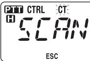
D

- To reverse the scan direction, turn the Tuning control clockwise (upward scan) or counterclockwise (downward scan). You can also press microphone [UP]/ [DWN].
• To quit the scan, press F (ESC). - When a CTCSS frequency is identified, the identified frequency appears on the display and blinks.


3 Press the Tuning control to program the identified frequency in place of the currently set CTCSS frequency.
- The CTCSS function will remain ON. To cancel CTCSS, press TONE until CT no longer appears on the display.
- Press F (ESC) if you do not want to program the identified frequency.
- Rotate the Tuning control while an identified frequency is blinking, to resume scanning.
Digital Code Squelch (DCS) is another application which allows you to ignore (not hear) unwanted calls. It functions the same way as CTCSS. The only differences are the encode/decode method and the number of selectable codes. For DCS, you can select from 104 different codes.
USING DCS
1 Select your desired band.
2 Press TONE 3 times to activate the DCS function.
- The DCS icon appears on the display when the DCS function is ON.
- Each press of TONE changes the selection as follows: Tone (T) -> CTCSS (CT) -> DCS (DCS) -> Off (no display).
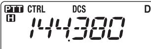
$$ \left| ^ {\text {田}} 4 3 0. 0 0 0 \right. $$
- The current DCS code appears on the display and blinks.

D
$$ \left| ^ {\text {田}} 4 3 0. 0 0 0 \right. $$
4 Rotate the Tuning control to select your desired DCS code.
• Refer to the table below for the available codes.
• To exit the DCS code selection, press F (ESC).
5 Press any key other than the Tuning control and F (ESC) to complete the setting.
6 When you are called: The transceiver squelch opens only when the selected DCS code is received.
When you make a call: Press and hold [PTT], then speak into the microphone.
- To cancel DCS, press TONE until DCS no longer appears on the display.
You can also select a DCS code by using the microphone:
1 Select your desired band.
2 Press TONE 3 times to activate the DCS function.
- The DCS icon appears on the display when the DCS function is ON.
- Each press of TONE changes the selection as follows: Tone (T) -> CTCSS (CT) -> DCS (DCS) -> Off (no display).
- The current DCS code appears on the display and blinks.
4 Press the key programmed as [ENTER].

5 Enter your desired DCS code using the microphone keypad.
• Refer to the table below for DCS codes.
| DCS Code | |||||||
| 023 | 025 | 026 | 031 | 032 | 036 | 043 | 047 |
| 051 | 053 | 054 | 065 | 071 | 072 | 073 | 074 |
| 114 | 115 | 116 | 122 | 125 | 131 | 132 | 134 |
| 143 | 145 | 152 | 155 | 156 | 162 | 165 | 172 |
| 174 | 205 | 212 | 223 | 225 | 226 | 243 | 244 |
| 245 | 246 | 251 | 252 | 255 | 261 | 263 | 265 |
| 266 | 271 | 274 | 306 | 311 | 315 | 325 | 331 |
| 332 | 343 | 346 | 351 | 356 | 364 | 365 | 371 |
| 411 | 412 | 413 | 423 | 431 | 432 | 445 | 446 |
| 452 | 454 | 455 | 462 | 464 | 465 | 466 | 503 |
| 506 | 516 | 523 | 565 | 532 | 546 | 565 | 606 |
| 612 | 624 | 627 | 631 | 632 | 654 | 662 | 664 |
| 703 | 712 | 723 | 731 | 732 | 734 | 743 | 754 |
DCS CODE ID
This function scans through all DCS codes to identify the incoming DCS code on a received signal. You may find it useful when you cannot recall the DCS code that the other persons in your group are using.
1 Press TONE 3 times to activate the DCS function.
- The DCS icon appears on the display when the DCS function is ON.
- Each press of TONE changes the selection as follows: Tone (T) -> CTCSS (CT) -> DCS (DCS) -> Off (no display).
- The DCS icon blinks and "SCAN" appears on the display.
- Scan starts when a signal is received.
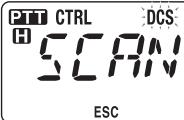
D

- To reverse the scan direction, turn the Tuning control clockwise (upward scan) or counterclockwise (downward scan). You can also press microphone [UP]/ [DWN].
• To quit the scan, press F (ESC). - When a DCS code is identified, the identified code appears on the display and blinks.
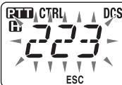
D
$$ \left| ^ {\text {田}} 4 3 0. 0 0 0 \right. $$
3 Press the Tuning control to program the identified code in place of the currently set DCS code.
- The DCS function will remain ON. To cancel DCS, press TONE until DCS no longer appears on the display.
- Press F (ESC) if you do not want to program the identified code.
- Rotate the Tuning control while an identified code is blinking, to resume scanning.
The keys on the microphone keypad function as DTMF keys; the 12 keys found on a push-button telephone plus 4 additional keys (A, B, C, D). This transceiver provides 10 dedicated memory channels. You can store a DTMF code with up to 16 digits.
Some repeaters in the U.S.A. and Canada offer a service called Autopatch. You can access the public telephone network via such a repeater by sending DTMF tones. For further information, consult your local repeater reference.
MANUAL DIALING
Manual Dialing requires only two steps to send DTMF tones.
1 Press and hold the microphone [PTT].
2 Press the keys in sequence on the keypad to send DTMF tones.
- The corresponding DTMF tones are transmitted.
- If the DTMF Hold function is activated, you need not hold down [PTT] while pressing keys. After transmitting the first tone (by pressing [PTT] and the first key), pressing additional keys will keep the transceiver in transmit mode for 2 seconds.
| Frequency (Hz) | 1209 | 1336 | 1447 | 1633 |
| 697 | [1] | [2] | [3] | [A] |
| 770 | [4] | [5] | [6] | [B] |
| 852 | [7] | [8] | [9] | [C] |
| 941 | [*] | [0] | [#] | [D] |
DTMF Hold
Activate this function to remain in transmit mode, after beginning to press keys when making a call.
1 Enter Menu mode and access Menu 300 (DT.HOLD) {page 20}.

ESC BACK

2 Set DTMF Hold to ON to continue transmitting when pressing keys.
- Set this menu to OFF to stop the 2 second continuous transmission.
AUTOMATIC DIALER
There are 10 dedicated DTMF Memory channels available to store DTMF codes. You can store up to 16 digits in each channel.
Storing a DTMF Code in Memory
1 Enter Menu mode and access Menu 301 (DT.MEM) {page 20}.

ESC
301

2 Rotate the Tuning control to select a channel number.
3 Press the Tuning control to set the selected channel number.
• The name entry display appears.

ESC
301


CLR
CH2
4 Enter a name for the channel {page 24}, the press the Tuning control to set it.
• The code entry display appears.

ESC
301


CLR
CH2
5 Enter a DTMF code for the channel {page 24}, then press the Tuning control to set it.
■ Transmitting Stored DTMF Codes
1 Press and hold the microphone [PTT].
2 While transmitting, press the Tuning control.
- The last called DTMF Memory channel name and number appear on the display. If no name has been saved for the channel, the DTMF code appears.

3 While still transmitting, rotate the Tuning control to select your desired DTMF Memory channel, then press the Tuning control to set the channel.
- Additionally, you can press a DTMF key corresponding to your desired channel ([0] \~ [9]) to select the channel and begin transmission.
- The stored DTMF code scrolls across the display and is transmitted.
- The code will be transmitted even if you release [PTT] before the entire code has scrolled across the display.
- If no DTMF code is stored in the selected channel, the frequency display is restored.
![PIT CTRL H D [CH2] H 430.000 ON AIR](/content/2025/01/83320/images/0eec16bae7e84c83c71a4b815af4a218e5d64e681f91a0c6a69e52b5c5f54f53.jpg)


■ Selecting a Transmit Speed
Some repeaters may not respond correctly if a DTMF code is transmitted at fast speed. If this happens, change the DTMF code transmission speed from FAST (default) to SLOW.
1 Enter Menu mode and access Menu 302 (DT.SPD) {page 20}.

2 Set the speed to FAST or SLOW.
■ Selecting a Pause Duration
You can change the pause duration stored in DTMF Memory channels; the default is 500 msec.
1 Enter Menu mode and access Menu 303 (DT.PAUS) {page 20}.

ESC

2 Select a speed (in msec) from the available list: 100/250/500/750/1000/1500/2000.
DTMF KEY LOCK
This function will lock the DTMF transmission keys so that they will not transmit if they are accidentally pressed. To lock the DTMF keys, turn this function ON.
1 Enter Menu mode and access Menu 304 (DT.LOCK) {page 20}.

ESC

2 Set the key lock to ON or OFF.
WHAT IS EchoLink?
EchoLink allows you to communicate with other amateur radio stations over the internet, using VoIP (voice-over-IP) technology. The EchoLink software program allows worldwide connections to be made between stations, or from computer to station, greatly enhancing your communications capabilities.
To use EchoLink, you must register using your call sign on their website and download the EchoLink software program (free of charge). Refer to the website for PC hardware and other requirements.
Official EchoLink Website: http://www.echolink.org
Note: EchoLink is a registered trademark of Synergenics, LLC.
STORING EchoLink MEMORY
There are 10 dedicated EchoLink DTMF Memory channels available to store DTMF codes. You can store up to 8 digits in each channel.
1 Enter Menu mode and access Menu 204 (ELK.MEM) {page 20}.

2 Rotate the Tuning control to select an EchoLink channel number from EL0 \~ EL9.
3 Press the Tuning control to set the selected channel number.
• The name entry display appears.
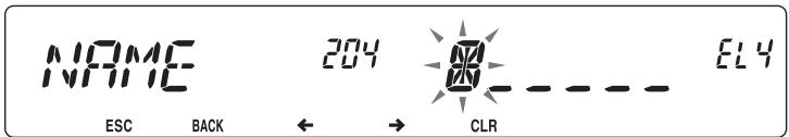
4 Enter the name for the channel {page 24}, then press the Tuning control to set it.
- The call sign and conference name (for board rooms that can do round QSO) of the other station which is connected via EchoLink, or the control command name, etc., are entered into the EchoLink memory name.
• The code entry display appears.
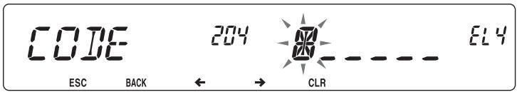
5 Enter a DTMF code for the channel {page 24}, then press the Tuning control to set it.
- The node number of the other station and conference which are connected via EchoLink, or the DTMF code of the control command, etc., are entered into the EchoLink code.
■ Transmitting EchoLink Memory
1 Press and hold the microphone [PTT].
2 While transmitting, press the Tuning control.
- The last called EchoLink DTMF Memory channel name and number appears on the display.

3 While still transmitting, rotate the Tuning control to select your desired EchoLink Memory channel, then press the Tuning control to set the channel.
- The stored code scrolls across the display and is transmitted.
Note:
In step 2, press the microphone [C] key before pressing the Tuning control, to transmit the converted DTMF code of the EchoLink "Connect by Call" function. (example: JA1YKX) "C" "51 21 10 93 52 92 #" (# is automatically added to the end of the DTMF code)
In step 2, press the microphone [0] [7] keys before pressing the Tuning control, to transmit the converted DTMF code of the EchoLink “Query by Call” function. (example: JA1YKX)
"0" "7" "51 21 10 93 52 92 #" (# is automatically added to the end of the DTMF code)
When only the EchoLink memory name has been registered, the EchoLink "Connect Call" function transmits the converted DTMF code. (example: JA1YKX)
"C 51 21 10 93 52 92 #" (C is automatically added to the beginning of the DTMF code and # is automatically added to the end)
◆ Call Sign/ DTMF Code Conversion Table
When a character other than an alphanumeric character is used (such as “-” and “/”), the DTMF conversion stops at the character before that non-standard character.
| 1 | 2 | 3 | 4 | 5 | 6 | 7 | 8 | 9 | 0 | |
| 0 | 1 | 2 | 3 | 4 | 5 | 6 | 7 | 8 | 9 | 0 |
| 1 | Q | A | D | G | J | M | P | T | W | |
| 2 | Z | B | E | H | K | N | R | U | X | |
| 3 | C | F | I | L | O | S | V | Y |
■ Selecting a Transmit Speed
Some repeaters may not respond correctly if a code is transmitted at fast speed. If this happens, change the EchoLink transmission speed from FAST (default) to SLOW.
1 Enter Menu mode and access Menu 205 (ELK.SPD) {page 20}.

ESC

2 Set the speed to FAST or SLOW.
SETTING UP EchoLink Sysop MODE
Connect the TM-V71 to a personal computer to use the system as a node station for EchoLink relaying.
When connecting to a personal computer and using the EchoLink Sysop mode, the hard flow control operation RTS and CTS computer terminals operate the same as and are changed with the SQC (squelch control signal output to the computer) and PKS (transmit control signal input from the computer) data terminals.
The current band becomes the same as the data band which is selected in menu No. 517, regardless of the transmission band and operation band.
Use the PG-5H (interface cable kit) when connecting to a personal computer.
1 Turn the transceiver power OFF.
2 Press [PF2] + Power ON to turn EchoLink Sysop Mode ON.
- The icon appears on the display when EchoLink Sysop mode is ON.
- When the audio signal is output to the PC side, the icon blinks.
PTT
H

D
H

[NO TEXT]
• To turn EchoLink Sysop Mode OFF, press [PF2] + Power ON again.
| EchoLink Sysop Mode ON | ||
| PC terminal | PC | |
| TxD | -> | RxD |
| RxD | <-- | TxD |
| SQC | -> | CTS |
| PKS | <-- | RTS |
| GND | <--> | GND |
| EchoLink Sysop Mode ON | ||
| PC terminal | PC | |
| TxD | -> | RxD |
| RxD | <-- | TxD |
| RTS | -> | CTS |
| CTS | <-- | RTS |
| GND | <--> | GND |
Note:
- We recommend you set Menu 520's SQC output setting to SQL when using EchoLink Sysop mode.
When using CTCSS or DCS, set the EchoLink “RX Monitor” function to “Busy only” (this can only be set with the MCP-2A) to verify the usage condition of the operating frequency. Because of this, when EchoLink Sysop mode is ON, all received signals on the DATA band side are output through the speaker, regardless of CTCSS and DCS mismatch. (Only when CTCSS or DCS matches, the voice signal is output from the data terminal.)
When EchoLink Sysop mode is ON, it cannot communicate with the MCP-2A. When using the MCP-2A, be sure to turn EchoLink Sysop mode OFF.
POWER-ON MESSAGE
Each time you switch the transceiver ON, "HELLO" (default) appears on the display for approximately 2 seconds. You can program your favorite message in place of the default message.
1 Enter Menu mode and access Menu 500 (P.ON.MSG) {page 20}.

2 Enter your desired message {page 24}.
- Press PF1 (CLR) to clear the entire message, if necessary.
DISPLAY BRIGHTNESS
You can manually change the display illumination to suit the lighting conditions where you are operating.
1 Enter Menu mode and access Menu 501 (BRIGHT) {page 20}.

2 Set your desired brightness level from 1 to 8, or OFF.
■ Auto Display Brightness
When Auto Brightness is activated, the display will light up every time a key is pressed.
1 Enter Menu mode and access Menu 502 (AUTO.BR) {page 20}.

2 Set the Auto Brightness function to ON or OFF.
■ Backlight Color
You can manually change the display illumination to suit the lighting conditions where you are operating.
1 Enter Menu mode and access Menu 503 (COLOR) {page 20}.

ESC
503

2 Set the backlight color to AMBER or GREEN.
KEY LOCK
The Key Lock function ensures that your transceiver settings will remain unchanged if you accidentally press a key. When activated, the following functions can still be used:
• [⏻]
• [PTT]
To turn Key Lock ON or OFF, press F (1s).
- When Key Lock is activated, the no icon will appear on the display.

D
$$ \left[ \begin{array}{l} 4 3 0 0 0 0 \end{array} \right] $$
#
■ Microphone Key Lock
The Microphone Key Lock function will lock the microphone PF (Progammable Function) keys.
1 Enter Menu mode and access Menu 513 (MIC.LCK) {page 20}.

ESC
5 13

2 Turn the Micrphone Key Lock function ON or OFF.
KEY BEEP
You can turn the transceiver beep function ON or OFF as desired.
1 Enter Menu mode and access Menu 000 (BEEP) {page 20}.

ESC

BACK

2 Turn the beep function ON or OFF.
- Even with the beep function turned OFF, the transceiver will emit a beep tone under the following conditions:
1) When Auto Power Off is activated, the transceiver will beep 1 minute before the power turns off.
2) After transmitting for the maximum time duration according to the Time-out Timer, the transceiver will beep
Beep Volume
Each time you press a key, the beep tone will sound. If you have left the beep function turned ON, you may wish to adjust the volume level of the beep.
1 Enter Menu mode and access Menu 001 (BP.VOL) {page 20}.

ESC


2 Set the beep volume to a level from 1 to 7.
• The default is level 5.
PROGRAMMABLE VFO
If you always check frequencies within a certain range, you can set upper and lower limits for frequencies that are selectable. For example, if you select 144 MHz for the lower limit and 145 MHz for the upper limit, the tunable range will be from 145.000 MHz to 146.995 MHz.
1 Press the left or right [BAND SEL] to set band A or B as the operating band, then press [VFO].
2 Enter Menu mode and access Menu 100 (PRG.VFO) {page 20}.
(Example: E type)


ESC
3 Press the Tuning control.
• The lower frequency limit blinks.

ESC

BACK

4 Rotate the Tuning control to select your desired lower frequency limit, then press the Tuning control to set the selected value.
• The upper frequency limit blinks.

ESC

BACK

- When setting the limit for the 1200 MHz band, the 1 MHz digit appears on the 7-segment display to the right of the main display.

ESC

BACK

5 Rotate the Tuning control to select your desired upper frequency limit, then press the Tuning control to set the selected value.
6 Press [CALL] (ESC) to exit Menu mode.
CHANGING THE FREQUENCY STEP SIZE
Choosing the correct frequency step size is essential in selecting your exact frequency. The default step size on the 144 MHz band is 5 kHz (K type) or 12.5 kHz (E, M4 types). The default on the 430/440 MHz band is 25 kHz. For K type models, the default on the 118, 220, or 300 MHz band is 12.5 kHz and the default on the 1200 MHz band is 25 kHz.
1 Press the left or right [BAND SEL] to select band A or B, then press [VFO].
2 Enter Menu mode and access Menu 101 (STEP) {page 20}.

ESC

BACK

3 Set the step size to 5.0*, 6.25*, or 8.33 kHz (118 MHz band only) or to 10.0, 12.5, 15.0*, 20.0, 25.0, 30.0, 50.0, or 100.0 kHz.
* These step sizes are not available for the 1200 MHz band.
PROGRAMMABLE FUNCTION KEYS
■ Transceiver Front Panel
There are 2 PF (Programmable Function) keys on the transceiver front panel: PF1 and PF2. You can assign your own desired functions to these 2 keys.
1 Enter Menu mode and access Menu 507 (PF1) and/or Menu 508 (PF2) {page 20}.

ESC
507

2 Set your desired function for the key. Programmable functions available are: WX CH (Weather Channel)/ FR.BAND (Frequency bands)/ CTRL (Control)/ MONI (Monitor)/ VGS (Voice recorder)/ VOICE (Voice announcement)/ GRP.UP (Memory group up)/ MENU (Menu mode)/ MUTE (Speaker Mute)/ SHIFT (Shift)/ DUAL (Dual Mode)/ M>V (Memory to VFO Copy)/ 1750 (1750 Hz Tone).
■ Microphone Keys
There are 4 microphone PF (Programmable Function) keys: [PF] (PF1), [MR] (PF2), [VF0] (PF3) and [CALL] (PF4). You can assign your own desired functions to these 4 keys.
1 Enter Menu mode and access Menu 509 (MIC.PF1) and/or Menu 510 (MIC. PF2) and/or Menu 511 (MIC. PF3) and/or Menu 512 (MIC. PF4) {page 20}.

ESC

2 Set your desired function for the key. Programmable functions available are: WX CH (Weather Channel)/ FR.BAND (Frequency bands)/ CTRL (Control)/ MONI (Monitor)/ VGS (Voice recorder)/ VOICE (Voice announcement)/ GRP.UP (Memory group up)/ MENU (Menu mode)/ MUTE (Speaker Mute)/ SHIFT (Shift)/ DUAL (Dual Mode)/ M>V (Memory to VFO Copy)/ VFO/ MR/ CALL/ MHz/ TONE/ REV (Reverse)/ LOW/ LOCK/ A/B (Band Select A/ Band Select B)/ ENTER/ 1750 (1750 Hz Tone).
FREQUENCY DIRECT ENTRY
If the desired operating frequency is far from the current frequency, using the microphone keypad is the quickest way to change the frequency. One of the microphone PF keys must first be programmed as ENTER {page 66},
1 Press the left or right [BAND SEL] to select band A or B, then press [VFO] or [CALL].
2 Press the key programmed as [ENTER].
• The Direct Frequency Entry display appears.
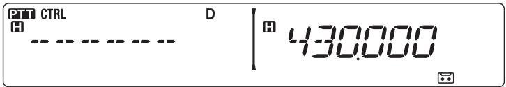
3 Press the microphone keys ([0] \~ [9]) to enter your desired frequency.
4 To set the entered frequency, press [ENTER] or [VFO].
- Pressing [ENTER] before entering all of the digits will set the remaining digits to 0.
- Pressing [VFO] before entering all of the digits will leave the remaining digits at their previous values.
- Entering all digits for a frequency will automatically set the frequency without pressing [ENTER] or [VFO].
- If you need to only change the MHz digit, press the Tuning control, then enter the new value.
AUTOMATIC POWER OFF (APO)
Automatic Power Off is a background function that monitors whether or not any operations have been performed (keys pressed, Tuning control turned, etc.), and turns the transceiver power OFF if it has not been in use.
1 Enter Menu mode and access Menu 516 (APO) {page 20}.

2 Set the APO time limit to 30, 60, 90, 120, 180 minutes, or OFF.
- After the time limit passes with no operations (default is 180 minutes), APO turns the transceiver power OFF. However, 1 minute before the power turns OFF, “APO” appears on the display and blinks, and a warning tone sounds.
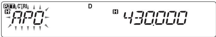
Note: If any settings are changed during while APO is ON, the timer resets. When you stop changing the settings, the timer begins counting again from 0.
S-METER SQUELCH
S-meter Squelch causes the squelch to open only when a signal with the same or greater strength than the S-meter setting is received. This function relieves you from constantly resetting the squelch when receiving weak stations that you have no interest in.
1 Enter Menu mode and access Menu 105 (S.SQL) {page 20}.

ESC


2 Set the S-Meter squelch to ON or OFF.
3 To select the desired S-meter setting, rotate the left (band A) or right (band B) SQL control depending on which band you have selected.
- The squelch will open only at the level you have selected (for example, level 9).

D
$$ \left| ^ {H} 4 3 0 0 0 0 \right. $$
■ Squelch Hang Time
When using S-meter Squelch, you may want to adjust the time interval between when the received signals drop and when the squelch closes.
1 Enter Menu mode and access Menu 106 (S.SQ.HNG) {page 20}.

ESC


2 Set the hang time to 125, 250, or 500 ms, or OFF.
ADVANCED INTERCEPT POINT (AIP)
The VHF/UHF band is often crowded in urban areas. AIP helps eliminate interference and reduce audio distortion caused by intermodulation. You can use this function only while operating on the VHF/UHF band.
1 Enter Menu mode and access Menu 103 (VHF.AIP) and/or Menu 104 (UHF.AIP) {page 20}.

ESC


2 Set the AIP to ON or OFF.
SWITCHING FM/AM MODE
This transceiver is also capable of receiving (not transmitting) in AM on band A. The default mode on the 118 MHz band is AM while the default on the 144, 220, 300, or 430/440 MHz band is FM.
1 Enter Menu mode and access Menu 102 (MODLAT) {page 20}.

ESC


2 Set the mode to AM, FM, or NFM.
Note: You cannot switch between FM and AM to receive on band B.
BEAT SHIFT
Since the transceiver uses a microprocessor to control various transceiver functions, the CPU clock oscillator's harmonics or image may appear on some spots of the reception frequencies. In this case, we recommend you turn the Beat Shift function ON.
1 Enter Menu mode and access Menu 108 (B.SHIFT) {page 20}.

ESC


2 Set the Beat Shift to ON or OFF.
SPEAKER MUTE
While receiving or transmitting on the TX band, you may not want to hear audio received on the other band. Use this function to mute the speaker allocated to that band (not the TX band).
While receiving, press F, LOW to switch the mute function ON or OFF.
- The MUTE icon appears on the display when the function is ON.
PTT
H

D
H

MUTE
■ Mute Hang Time
When using Speaker Mute, you may want to adjust the time interval between when you receive a signal and when the speaker is muted.
1 Enter Menu mode and access Menu 107 (MUT.HNG) {page 20}.
MUTHING 107
ESC
BACK

2 Set the hang time to 125, 250, 500, 750, or 1000 ms.
SELECTING AN OUTPUT POWER
It is a good idea to select lower transmit power if communications is still reliable. This lowers the risk of interfering with others on the band. When operating from battery power, you will enjoy more operating time before a recharge is necessary.
Press LOW to select high (H) (K, E types only), medium (M), or low (L) power.
- You can program different power settings for bands A and B.

$$ \left\lvert \begin{array}{l} \texttt {M} 4 3 0. 0 0 0 \end{array} \right. $$
Note: When the transceiver overheats because of ambient high temperature or continuous transmission, the protective circuit may function to lower transmit output power.
TIME-OUT TIMER (TOT)
It is sometimes necessary or desirable to restrict a single transmission to a specific maximum time. You may use this function to prevent repeater time-outs when accessing repeaters, or to conserve battery power.
When TOT times out (default is 10 minutes), the transceiver generates beeps and automatically returns to receive mode. To resume transmitting, release and then press the microphone [PTT] again.
1 Enter Menu mode and access Menu 109 (TOT) {page 20}.
TOT
ESC
BACK
109

2 Set the timer to 3, 5, or 10 minutes.
EXTERNAL SPEAKER CONFIGURATION
This transceiver has two speaker jacks for external speakers, as well as an internal speaker. You can enjoy a variety of speaker configurations by using one or two external speakers. Received signals on bands A and B are output depending on how you want the internal and/or external speakers to function.
1 Enter Menu mode and access Menu 002 (EXT.SP) {page 20}.

ESC


2 Set the speaker mode to MODE 1 or MODE 2.
• Refer to the table below for configurations based on the mode selected.
| Mode | Speaker Setup | Band Output | ||
| Internal Speaker | External SP1 | External SP2 | ||
| MODE 1 | None | A, B | - | - |
| SP1 only | x | A, B | - | |
| SP2 only | A | - | B | |
| SP1, SP2 | x | A | B | |
| MODE 2 | None | A, B | - | - |
| SP1 only | x | A, B | - | |
| SP2 only | B | - | A | |
| SP1, SP2 | x | B | A | |
MASKING A BAND
If you have no plans to use band A or B, you can hide the frequency display on the unused band. This saves power consumption and makes it simpler to read the information you need.
1 Turn the transceiver power OFF.
2 Press the left or right [BAND SEL] + Power ON.
• The band mask display appears.


3 Rotate the Tuning control to select the band you want to hide (or return to normal).
4 Press the Tuning control to set the selected band.
5 Rotate the Tuning control to set the band to select USE or MASK.
- USE allows you to see and use the band as normal. MASK hides the band on the display.

ESC

BACK

6 Press the Tuning control to set the selection.
7 Press the [CALL] (ESC) to exit.
Note: You cannot operate the masked band nor use it to receive or transmit.
DISPLAY PARTITION BAR
The partition bar that appears between bands A and B can be removed if desired.
1 Enter Menu mode and access Menu 527 (DP.BAR) {page 20}.

ESC


2 Set the partition bar display to ON or OFF.

H

D


H

D


WEATHER ALERT (K TYPE MODELS ONLY)
The Weather Alert is available only in the USA and Canada. When activated, this function will check for a received NOAA 1050 Hz tone. When the tone is received, the weather alert tone will sound.
1 Enter Menu mode and access Menu 110 (WX.ALT) {page 20}.

ESC BACK


2 Set the Weather Alert to ON or OFF.
- When activated, the WX icon appears on the display.
- When a signal is being received, the WX icon blinks.
■ Weather Channel
Whether or not the Weather Alert is activated, you can still access the weather channels. The Weather Alert simply notifies you of activity on the weather channels.
1 Press the key programmed with the WX function.
2 Rotate the Tuning control to select your desired channel.
| Channel No. | Frequency (MHz) | Memory Name | Location |
| A1 | 162.550 | WX 1 | NOAA/ Canada |
| A2 | 162.400 | WX 2 | NOAA/ Canada |
| A3 | 162.475 | WX 3 | NOAA/ Canada |
| A4 | 162.425 | WX 4 | NOAA |
| A5 | 162.450 | WX 5 | NOAA |
| A6 | 162.500 | WX 6 | NOAA |
| A7 | 162.525 | WX 7 | NOAA |
| A8 | 161.650 | WX 8 | Canada |
| A9 | 161.775 | WX 9 | Canada |
| A10 | 163.275 | WX 10 | - |
POWER ON PASSWORD
If power on password is activated, you cannot operate the transceiver without first entering your password, after turning the transceiver power ON. Your password can be changed using the MCP-2A software, and can contain up to 6 digits.
1 Enter Menu mode and access Menu 998 (PASSWD) {page 20}.

ESC BACK

2 Set the power on password to ON or OFF.
- When set to ON, "PASSWD" appears on the display.

1

3
5
3 Enter your password.

1

3
5
4 After entering up to 6 digits, press the Tuning control to set the password.
Note: Even with Menu 998 turned ON, the power on password function will not be activated unless you first program a password using the MCP-2A software.
When using the optional VGS-1 voice guide & storage unit, you gain access to the voice recorder and voice announcement functions.
Note: The VGS-1 is sold depending upon area.
VOICE ANNOUNCEMENTS
When changing modes, frequencies, settings, etc., an audio voice will announce the new information.
1 Enter Menu mode and access Menu 003 (ANN) {page 20}.

ESC
003

2 Set the announcement function to MANUAL, AUTO, or OFF.
• Refer to the tables below for announcements based on settings.
| MANUAL:A microphone PF key must be programmed as [VOICE] to use MANUAL voice announcement. | |
| Operation | Announcement |
| While in VFO mode | Press [VOICE]:Operating band frequency |
| While in MR mode | Press [VOICE]:“Channel” + Channel number + operating band frequency |
| While in Call mode | Press [VOICE]:“Call channel” + operating band frequency |
| While in Menu mode | Press [VOICE]:Menu number or setting value (some selections have no voice announcement) |
| Tone frequency setup | Press [VOICE]:“Tone frequency” + frequency value |
| CTCSS frequency setup | Press [VOICE]:“CTCSS frequency” + frequency value |
| DCS code setup | Press [VOICE]:“DCS” + code value |
| AUTO:Announcements are made automatically when changing a mode/frequency/setting. | |
| Operation | Announcement |
| Press [VFO] | “VFO” |
| Press [MR] | “MR” |
| Press [CALL] | “Call” |
| Press [F] | “Function” |
| Press [MENU] | “Menu” + menu number |
| Press [PM] | “PM” |
| Press [ENT] | “Enter” |
| Change the operating band/turn the power ON | “A”/“B” + “Channel” (for MR only) + “Call”/channel number + “Channel” (for CALL only) + operating band frequency + output power level |
| Change the frequency band | New receive frequency |
| Frequency direct entry | Entered key number |
| Memory Direct Entry mode | Channel number |
| Press [F] in VFO mode | “Memory in” + channel number + frequency |
| Press [F], [M.IN] in VFO mode | “Memory in” + channel number + “Blank” |
| Press [A/B] in VFO mode | “A”/“B” + frequency + output power level |
| Press [F] and then the Tuning control in VFO mode | “Menu” + menu number |
| Press the Tuning control in Menu mode | Setting value |
| Perform a Full Reset | “Full reset?” |
| Perform a Partial Reset | “Partial reset?” |
| Perform a VFO Reset | “VFO reset?” |
| Perform a PM Reset | “PM reset?” |
| Press [LOCK] (to turn the Lock function ON) | “Lock on” |
| Press [LOCK] (to turn the Lock function OFF) | “Lock off” |
| Tone frequency setup | “Tone frequency” + frequency value |
| CTCSS frequency setup | “CTCSS frequency” + frequency value |
| DCS code setup | “DCS” + code value |
| MHz step frequency setup | “MHz Step” + frequency value |
| 10 MHz setup | “10” + “MHz setup” + frequency value |
| Output power setup | “TX Power” + power level |
■ Voice Announcement Language
1 Enter Menu mode and access Menu 004 (ANN.LNG) {page 20}.

ESC BACK

2 Set the language to ENG (English) or JPN (Japanese).
■ Voice Announcement Volume
1 Enter Menu mode and access Menu 005 (ANN.VOL) {page 20}.

ESC BACK

2 Set the announcement volume level from 1 to 7.
• To turn the volume OFF, turn the announcement function OFF.
■ Voice Announcement Speed
1 Enter Menu mode and access Menu 006 (ANN.SPD) {page 20}.

ESC BACK

2 Set the announcement speed level from 0 to 4.
• The speed settings are as follows:
0: 0.85 times normal speed
1: Normal speed
2: 1.15 times normal speed
3: 1.30 times normal speed
4: 1.45 times normal speed
VOICE RECORDER
The voice recorder provides you with 3 VGS channels for recording voice memos, along with a single VGS channel for continuous recording. You can also prepare automated message responses to received calls.
Each recording can last for up to 30 seconds.
■ Voice Memos
To record a voice memo, for later playback:
1 Press the PF key programmed as [VGS].

2 Press and hold the key for the VGS channel number you want to store the memo in: F (1), TONE (2), or REV (3).
- A beep will sound and the transceiver will enter Recording mode.

3 Press and hold the VGS channel number key again (the same key you pressed in the previous step), then speak into the microphone to record your memo.
- Recording begins as soon as you press the VGS channel number key, and a timer appears on the display.
- Pressing the microphone PTT switch at this time will transmit your message as well as record it. Do not press the microphone PTT switch if you do not want to transmit your message.

4 Release the VGS channel number key to end the recording at any time and store it into the selected VGS channel.
- If the memory becomes full, recording will stop automatically and store the voice memo to memory.
- “WRITING” appears on the display while the recording is being stored to memory.

• To exit, press [VGS] again.
■ Continuous Recording
Received signals on the control band are continuously recorded, with the memory retaining the last 30 seconds of recorded signals.
1 Enter Menu mode and access Menu 009 (CON.REC) {page 20}.

ESC

BACK

2 Set the Continuous Recording to ON (or OFF).
- The 📄 icon appears on the display when this function is activated. The 📄 icon does not appear during playback, in Repeater mode, or in Remote Control mode.
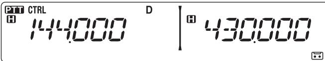
3 Press the PF key programmed as [VGS].

4 Press LOW (4) (1s) to store the recorded signals in VGS channel 4.

■ Playback
1 Press the PF key programmed as [VGS].
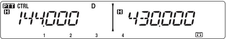
- When preparing to transmit, press the [PTT] switch before pressing the channel number (1 - 3) key.
2 Press the key for the VGS channel number you want to play back: F (1), TONE (2), REV (3), or LOW (4) (when the Continuous Recording is ON.)
- The recording saved in the channel you selected is played back.

• To end playback at any time, press PF1 (CLR).
• To exit, press [VGS] again.
- During playback, you can switch to any of recordings 1, 2, 3, or 4 by pressing the appropriate key.
■ Playback Repeat
You can set messages to be repeatedly played back.
1 Enter Menu mode and access Menu 007 (PLAY.BK) {page 20}.

2 Set the the Playback Repeat function to ON or OFF.
■ Playback Repeat Interval
If the Playback Repeat function is activated, you can set a time interval for how often the memo/message is played back.
1 Enter Menu mode and access Menu 008 (P.BK.INT) {page 20}.

2 Set the interval from 0 to 60 seconds.
This transceiver is capable of receiving signals on one band and retransmitting signals on the other band. This function repeats signals originating from one band, using the other band. For example, a signal received on band A (VHF) is retransmitted on band B (UHF). Similarly, a signal received on band B (UHF) is retransmitted on band A (VHF).
Locked-band Repeater: The transceiver uses the same band to receive or transmit a signal. You can set either the A band (A-TX) or B band (B-TX) as the transmit band.
Cross-band Repeater: If receiving a signal on the TX band, the transceiver switches the current RX only band to the TX band. This is useful when joining in a group talk. Participants in a group talk need to set a receive and transmit frequency on different bands so as not to miss any conversation within the group.
1 Enter Menu mode and access Menu 403 (RPT.MOD) {page 20}.
$$ R P T M O I 4 0 3 $$
ESC

2 Set the Repeater operation mode to CROSS (cross-band), A-TX (A band), or B-TX (B band).
3 Turn the transceiver power OFF.
4 Press TONE + Power ON.
- The Repeater mode is ON and the PTT and no icons blink on the display.
- You are unable to perform any transceiver functions while in Repeater mode.
- To return to normal operation, turn the transceiver power OFF, then press TONE + Power ON.
Note:
You cannot activate the Repeater function while in single band operating mode or Weather Channel mode.
◆ Activating the Repeater function switches OFF the Automatic Simplex Checker (ASC).
◆ The Time-Out Timer is locked at 3 minutes.
◆ Resetting the transceiver {page 88} will not cancel the Repeater mode.
REPEATER HOLD
If necessary, you can set the transceiver to remain in the transmit mode for 500 ms after a signal drops.
1 Enter Menu mode and access Menu 404 (RPT.HLD) {page 20}.

ESC

2 Set the Repeater Hold function to ON or OFF.
REPEATER ID
If necessary, you can set the transceiver to transmit your call sign every 10 minutes.
1 Enter Menu mode and access Menu 406 (ID.TX) {page 20}.

ESC


2 Set the ID Trasmit function to OFF, MORSE, or VOICE.
- To use VOICE transmission, you must have the VGS-1 option installed. When using the VGS-1 option, the ID Transmit function will use VGS channel 3 as the call sign {page 78}.
- When selecting MORSE, the call sign stored in Menu 405 {see below} will be transmitted at 20 wpm (words per minute).
■ Entering your Repeater ID
1 Enter Menu mode and access Menu 405 (RPT.ID) {page 20}.

ESC

←

natural_image
Simple graphic with a starburst and a dashed line, no text or symbols present.CLR
2 Enter your call sign {page 24}.
Connect this transceiver to your personal computer via a Terminal Node Controller (TNC). You can send messages or commands to far away stations, obtain a variety of information via your local bulletin boards, or enjoy other Packet applications. Reference material for starting Packet operation should be available at any store that handles Amateur Radio equipment.
Note:
When the distance between the radio antenna and your personal computer is too close, interference may occur.
Do not share a power source between the transceiver and the TNC. When the distance between the TNC and your personal computer is too close, interference may occur.
Data terminal pins:
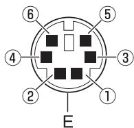
| No. | Name | I/O | Function |
| 1 | PKD | Input | Audio signal for packet transmission |
| 2 | DE | — | PKD terminal ground |
| 3 | PKS | Input | ‘L’ is transmitted and the microphone is muted |
| 4 | PR9 | Output | 9600 (bps) repeat signal |
| 5 | PR1 | Output | 1200 (bps) repeat signal |
| 6 | SQC | Output | Squelch control signal; Closed: ‘L’, Open: ‘H’(The default settings can be changed in Menu 520) |
| E | — | Common ground |
DATA BAND
Select how data will be transmitted and received on your transceiver.
1 Enter Menu mode and access Menu 517 (DAT.BND) {page 20}.

2 Set the data band to A (A band receives and transmits), B (B band receives and transmits), ATX.BRX (A band transmits and B band receives), or ARX.BTX (A band receives and B band transmits).
DATA TERMINAL SPEED
Select 1200 or 9600 bps for the data transfer rate, depending on your TNC.
1200 bps: Transmit data input (PKD) sensitivity is 40 mV _p-p , input impedance is 10 kΩ.
9600 bps: Transmit data input (PKD) sensitivity is 2 V_p-p , input impedance is 10 kΩ.
1 Enter Menu mode and access Menu 518 (DAT.SPD) {page 20}.

ESC BACK

2 Set the data speed to 1200 or 9600 bps.
PC PORT SPEED
You can adjust the speed at which the computer and transceiver exchange information, when the transceiver is connected to your computer.
1 Enter Menu mode and access Menu 519 (PC.SPD) {page 20}.

ESC BACK

2 Set the PC port speed to 9600, 19200, 38400, or 57600 bps.
- Turning the power ON/OFF will change the port speed setting.
SQC OUTPUT SETTING
You can set the condition for which the SQC output terminal becomes active.
1 Enter Menu mode and access Menu 520 (SQC.SRC) {page 20}.

ESC BACK

2 Set the SQC output activation method to one of the following:
• OFF: SQC output remains inactive.
- BUSY: When a signal is received on the data band, the SQC output becomes active.
- SQL: While CTCSS/DCS is ON and a matching signal is received, the SQC output becomes active. While CTCSS/DCS is OFF, the SQC output becomes active when a busy signal is received.
• TX: While transmitting, the SQC output becomes active.
- BUSY.TX: When the conditions of BUSY and TX (above) are met, the SQC output becomes active.
- SQL.TX: When the conditions of SQL and TX (above) are met, the SQC output becomes active.
Note: The activation type (logic) can be changed using the MCP-2A software.
If you also have a compatible Kenwood handy transceiver, you may use it as a remote control for this mobile transceiver. You will control one band on the mobile while sending DTMF tones to the other band from the handheld. This function is useful, for example, when you want to control the mobile from a location outside your vehicle.
Note:
As a remote control, you can also use a handy transceiver which does not have a remote control function but a DTMF function. However, you must manually send DTMF tones for control code strings. Skip steps 1 and 3 in “PREPARATION”.
◆ The FCC rules permit you to send control codes only on the 440 MHz band.
PREPARATION
Let us assume band A (VHF) of the mobile transceiver will be controlled.
On the handy transceiver:
1 Program a 3-digit secret number.
- For the programming method, see the instruction manual for the handheld.
2 Select the transmit frequency on the UHF band.
3 Make the handheld enter Remote Control mode.
- For the method, see the instruction manual for the handheld. If not described, consult your dealer.
On the mobile transceiver:
4 Enter Menu mode and access Menu 522 (REM.ID) {page 20}.

5 Set the ID code to the same secret number you set on the handy transceiver.
6 Select the receive frequency on band B (UHF).
- Match this frequency with the transmit frequency on the handheld.
7 Select band A (VHF) as the TX band or Control band.
8 To cause the mobile to send a control acknowledgment to the handheld, enter Menu 523 (ANS.BK) and set it to ON.
- DTMF tones which represent the secret number will be used as an acknowledgment.

9 Turn the transceiver power OFF.
10 Press [REV] + Power ON to enter Remote Control mode.
- The CTRL and mo icons appear on the display.
- To exit Remote Control operation, turn the transceiver power OFF, then press REV + Power ON again.
CONTROL OPERATION
While in Remote Control mode, the DTMF keys of the handheld will function as shown in the table below. Each time you press the desired key, the handheld will automatically enter transmit mode and send the corresponding command to the mobile.
Note: If using a handheld without a remote control function, manually send "AXXX#YA#" where "XXX" is a 3-digit secret number and "Y" is a single-digit control command. If you do not add "A#" to the end, you can skip sending "AXXX#" next time; however, the mobile may be accidentally controlled by other stations.
| Operation | DTMF Command |
| Access your mobile via the remote unit (where *** is your 3-digit secret number) | A *** # |
| End access of your mobile via the remote unit | A # |
| DCS ON | 1 |
| Tone ON | 2 |
| CTCSS ON | 3 |
| DCS OFF (all signalling OFF) | 4 |
| Tone OFF (all signalling OFF) | 5 |
| CTCSS OFF (all signalling OFF) | 6 |
| Call mode ON | 7 |
| VFO mode ON | 8 |
| Memory mode ON | 9 |
| Transmit power (press to toggle between High, Medium, and Low) | 0 |
| Frequency (in VFO mode) or Memory channel (in Memory mode) directly entry | A XXXXXXX |
| DCS code (when DCS is ON), Tone frequency (when Tone is ON), or CTCSS frequency (when CTCSS is ON) setup | B XXX(DCS code)BA XXX (Tone/CTCSS frequency |
| Repeater (Cross-band or Locked-band) ON | C |
| Repeater OFF | D |
| Step the frequency or Memory channel down | * |
| Step the frequency or Memory channel up | # |
There are 4 types of transceiver reset available:
VFO Reset
Use to initialize the VFO and accompanying settings.
PART (Partial) Reset
Use to initialize all settings other than the Memory channels, the DTMF memory, and the PM channels.
PM Reset
Use to reset only the Programmable Memory channels to their default values.
FULL Reset
Use to initialize all transceiver settings that you have customized.
There are 2 ways to perform a reset on the transceiver: by key operation and by accessing Menu mode.
Key Operation:
1 Turn the transceiver power OFF.
2 Press F + Power ON.
3 Rotate the Tuning control and select your desired reset type: VFO, PART, PM, or FULL.

ESC

4 Press the Tuning control to set the reset type.
• A confirmation message appears on the display.

ESC

- Press TONE (BACK) to return to the previous display or F (ESC) to cancel the reset.
5 Press the Tuning control again to perform the reset.


Note: When in Remote Control or Repeater mode, you cannot reset the transceiver using the Key Operation method.
Menu Mode:
1 Enter Menu mode and access Menu 999 (RESET) {page 20}.

ESC


2 Set the reset type to VFO, PART, PM, or FULL.
3 Press the Tuning control to set the reset type.
• A confirmation message appears on the display.

ESC


- Press TONE (BACK) to return to the previous display or F (ESC) to cancel the reset.
4 Press the Tuning control again to perform the reset.


Note: When the Channel Display function or Key Lock function is ON, the transceiver reset cannot be performed.
The following options are available for use with this transceiver:
| DFK-3D | Detachable Front Panel Kit (3 m) | PG-3B | Noise Filter |
| MC-45 | Microphone | PG-5A | Data Cable |
| MC-59 | Microphone with keypad | PG-5G | Programming Interface Cable (2 m) |
| MCP-2A | Memory Control Program (web download software) | PG-5H | PC Interface Cable Kit (2 m) |
| MJ-88 | Microphone Plug Adapter | PG-5F | Extension Cable Kit (4 m) |
| MJ-89 | Modular Plug Microphone Switch | PS-33 | DC Power Supply |
| PS-53 | DC Power Supply | ||
| PG-2N | DC Cable (2 m) | SP-50B | External Speaker |
| PG-20 | DC Cable (7 m) | VGS-1 | Voice Guide & Storage Unit |
Note: Optional accessories for use with this transceiver may change, post-production. (New options may become available and/or current options may be discontinued.) Please refer to the options catalog(s) for applicable transceivers.
MEMORY CONTROL PROGRAM MCP-2A
The following functions can be set only by using the MCP-2A software:
- SQC active condition
• Microphone sensitivity level
• 10 MHz mode selection
• Power on password value
Using the MCP-2A software, you can:
• View memory channel groups
• Name memory groups
• Name PM channels
- Save/load settings
- Read exported TravelPlus for Repeaters™ files issued from the ARRL™
• Print/export memory and various settings in html
(TravelPlus for Repeaters is a trademark of ARRL.)
To download the MCP-2A software, go to:
http://www.kenwood.com/i/products/info/amateur/software_download.html
Note: This URL may change without notice.
■ Using the MCP-2A Software
1 Follow the directions of the installer to install the software.
2 Set up the PC COM port and baud rate.
3 The transceiver data is read from the MCP-2A software.
4 Select your desired settings, then write the data to the transceiver.
CONNECTING THE PG-5G/PG-5H INTERFACE CABLES
The PG-5G package comes with cable ② (below).
The PG-5H packages comes with cables ① and ② (below).
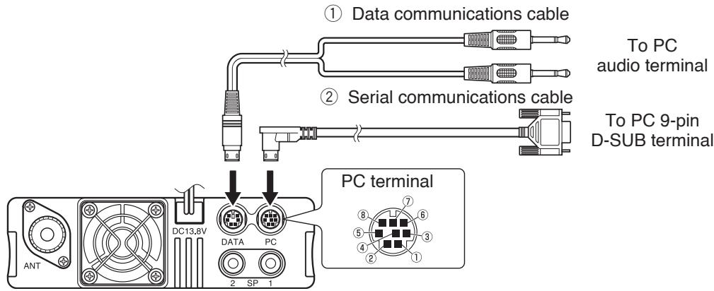
PC terminal pins:
| No. | Name | I/O | Function |
| 1 | RTS | O | Request to Send |
| 2 | CTS | I | Clear to Send |
| 3 | TXD | O | Transmit Data |
| 4 | GND | — | GND |
| 5 | RXD | I | Receive Data |
| 6 | NC | — | — |
| 7 | NC | — | — |
| 8 | NC | — | — |
• For DATA terminal, refer to page 83.
Data communications cable pin configuration
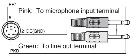
Serial communications cable pin configuration (cross connection)
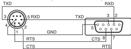
Note: When connecting the regular cable in your vehicle, the terminal may disconnect due to vibrations. Be sure to lock the cable in place.
INSTALLING THE DFK-3D PANEL KIT
■ Installing the Sub-Panel
1 Detach the front operation panel from the base unit, then remove the modular cable from both sides.
2 Connect the 4-pin connector of the supplied modular cable to the operation panel.
- Align the cable with the cable guide.
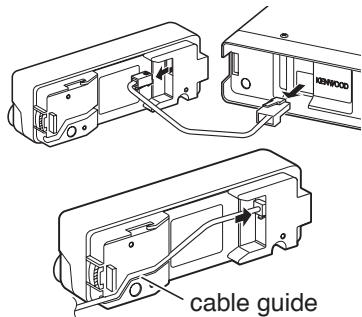
3 Connect the supplied sub-panel to the operation panel.
- Install the sub-panel in a manner so as not to disrupt the cable.
4 Connect the 8-pin connector of the supplied modular cable to the base unit.
- The line filter is pre-installed onto the cable.
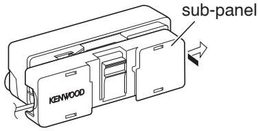
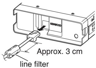
Installing the Panel Bracket
1 Clean and dry the installation location.

Do not install the bracket close to an air bag.
2 Remove the release paper from the base of the panel bracket, then secure it in place using the 3 supplied self-tapping screws.
- Allow the panel to set for a while, to ensure it remains fast. Otherwise, vibrations may occur.
- After removing the release paper, it cannot be reused.
3 Attach the panel holder to the base bracket using the 2 supplied SEMS screws.
4 Attach the operation panel to the panel holder so that it locks in place.
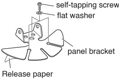
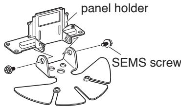
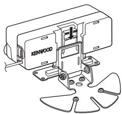
natural_image
Technical line drawing of a Kenwood industrial machine with mounting flanges (no text or symbols)CONNECTING THE PG-5F EXTENSION CABLE
If necessary, the PG-5F extension cable kit can be used with the DFK-3D panel kit. Using two PG-5F kits, you can extend the cables to the maximum length. (Components marked with an asterisk * are included in the PG-5F kit.)
Connecting Using a Single Extension Kit
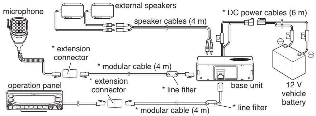
flowchart
graph TD
    A["microphone"] --> B["external speakers"]
    B --> C["speaker cables (4 m)"]
    C --> D["DC power cables (6 m)"]
    D --> E["12 V vehicle battery"]
    F["operation panel"] --> G["extension connector"]
    G --> H["extension connector"]
    H --> I["modular cable (4 m)"]
    I --> J["* line filter"]
    J --> K["base unit"]
    K --> L["* line filter"]
    L --> M["modular cable (4 m)"]
Connecting Using Two Extension Kits
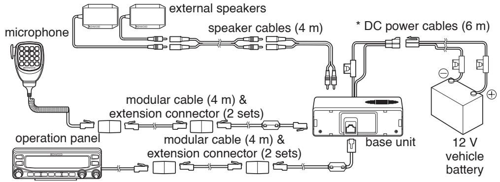
flowchart
graph TD
    A["microphone"] --> B["external speakers"]
    B --> C["speaker cables (4 m)"]
    C --> D["* DC power cables (6 m)"]
    D --> E["base unit"]
    E --> F["12 V vehicle battery"]
    G["operation panel"] --> H["modular cable (4 m) & extension connector (2 sets)"]
    H --> I["modular cable (4 m) & extension connector (2 sets)"]
    I --> J["bus"]
    J --> K["bus"]
    K --> L["bus"]
    L --> M["bus"]
    M --> N["bus"]
    N --> O["bus"]
    O --> P["bus"]
    P --> Q["bus"]
    Q --> R["bus"]
    R --> S["bus"]
    S --> T["bus"]
    T --> U["bus"]
    U --> V["bus"]
    V --> W["bus"]
    W --> X["bus"]
    X --> Y["bus"]
    Y --> Z["bus"]
Installing the Line Filter
Install the line filter approximately 3 cm from the connector which attaches to the base unit.
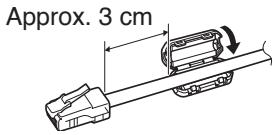
■ Affixing the Microphone Cable
Lock the microphone cable down as shown in the illustration.
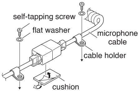
INSTALLING THE VGS-1 UNIT
Follow the instructions below to install the VGS-1 unit.
1 Remove the 8 screws from the cover of the base unit, then remove the cover itself from the unit.
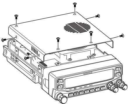
2 From the 5 black cushions supplied with the VGS-1, select the thickest rectangular cushion (20 x 30 x 12 mm) and attach it to the top surface of the VGS-1 unit.
- To prevent interference to the terminal of the VGS-1, ensure that you attach the thick square cushion to the baseplate surface.
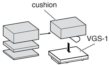
3 From the remaining cushions, select the thickest square cushion (21 x 21 x 2.5 mm) and attach it to the printed circuit board.
- The remaining cushions are not used with this transceiver.
- Ensure that the cushion is placed within the guidelines on the PCB.
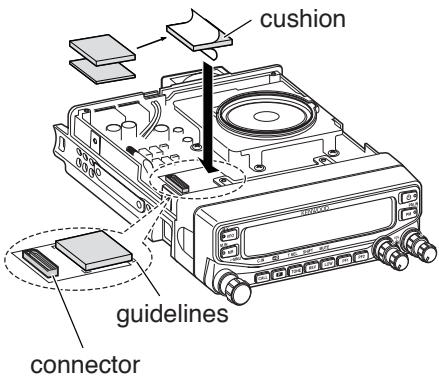
4 Insert the VGS-1 unit into the connector on the transceiver.
- Press down on the top of the VGS-1 unit to ensure that it is securely attached to the connector.
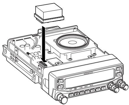
natural_image
Technical line drawing of a CD or DVD drive with ports and a box, no text or symbols present5 Replace the cover on the base unit and secure it using the 8 screws.
GENERAL INFORMATION
This product has been factory aligned and tested to specification before shipment. Attempting service or alignment without factory authorization can void the product warranty.
SERVICE
When returning this product to your dealer or service center for repair, pack it in its original box and packing material. Include a full description of the problem(s) experienced. Include your telephone number along with your name and address in case the service technician needs to contact you; if available, also include your fax number and e-mail address. Don't return accessory items unless you feel they are directly related to the service problem.
You may return this product for service to the authorized Kenwood dealer from whom you purchased it, or any authorized Kenwood service center. Please do not send subassemblies or printed circuit boards; send the complete product. A copy of the service report will be returned with the product.
SERVICE NOTE
If you desire to correspond on a technical or operational problem, please make your note legible, short, complete, and to the point. Help us help you by providing the following:
- Model and serial number of equipment
• Question or problem you are having - Other equipment in your station pertaining to the problem

Do not pack the equipment in crushed newspapers for shipment! Extensive damage may result during rough handling or shipping.
Note:
◆ Record the date of purchase, serial number and dealer from whom this product was purchased.
For your own information, retain a written record of any maintenance performed on this product.
When claiming warranty service, please include a photocopy of the bill of sale or other proof-of-purchase showing the date of sale.
CLEANING
To clean the case of this product, use a neutral detergent (no strong chemicals) and a damp cloth.
TROUBLESHOOTING
The problems described in this table are commonly encountered operational malfunctions and are usually not caused by circuit failure.
| Problem | Probable Cause | Corrective Action |
| The transceiver will not power up after connecting a 13.8 V DC power supply and pressing [⏻]. Nothing appears on the display. | 1 The power cable was connected backwards.2 One or more of the power cable fuses are open. | 1 Connect the supplied DC power cable correctly (red to + terminal and black to - terminal).2 Look for the cause of the blown fuse(s). After inspecting and correcting any problems, install a new fuse(s) with the same ratings. |
| The frequency cannot be selected by turning the Tuning control or by pressing microphone [UP]/[DWN]. | Memory Recall was selected. | Press [VFO]. |
| Most keys and the Tuning control do not function. | 1 One of the Lock functions is ON.2 The transceiver is in Channel Display mode. | 1 Unlock all of the Lock functions.2 With the transceiver power OFF, press [LOW] + Power ON to exit Channel Display mode. |
| Memory channels cannot be selected by turning the Tuning control or by pressing microphone [UP]/[DWN]. | No data has been stored in any Memory channel. | Store data in some Memory channels. |
| You cannot transmit even though you are pressing [PTT]. | 1 The microphone plug was not inserted completely into the transceiver.2 You selected a transmit offset that places the transmit frequency outside the allowable range.3 The external TNC is transmitting. | 1 Switch the power OFF, then insert the microphone plug until the locking tab clicks in place.2 Turn the offset shift function OFF.3 Press [PTT] after the TNC has finished transmitting. |
Specifications are subject to change without notice due to advancements in technology.
| General | TM-V71A | TM-V71E | TM-V71A | |||
| K Type | E Type | M4 Type | ||||
| Guaranteed range | Band A & B | TX & RX | 144 ~ 148 MHz | 144 ~ 146 MHz | ||
| 438 ~ 450 MHz | 430 ~ 440 MHz | |||||
| Frequency range | Band A | RX | 118 ~ 524 MHz | — | ||
| Band B | 136 ~ 524 MHz | — | ||||
| 800 ~ 1300 MHz(K type: excluding cellular band) | — | |||||
| Mode | F2D/ F3E | |||||
| Antenna impedance | 50 Ω | |||||
| Operating temperature range | -20°C ~ +60°C (-4°F ~ +140°F) | |||||
| Power requirement | 13.8 V DC ±15% (Negative ground) | |||||
| Frequency stability | Within ±5 ppm (-10°C ~ +50°C) | |||||
| Current | TX | VHF | Hi | Less than 13.0 A | — | |
| Mid | Less than 5.5 A | Less than 9.0 A | ||||
| Low | Less than 4.0 A | |||||
| UHF | Hi | Less than 13.0 A | — | |||
| Mid | Less than 6.5 A | Less than 9.0 A | ||||
| Low | Less than 5.0 A | |||||
| RX | Less than 1.2 A (at 2W audio output) | |||||
| Dimensions (W x H x D) | Without projections | Panel: 140 x 43 x 38.2 mm (5.51" x 1.69" x 1.50")Body (with Panel): 140 x 43 x 180.7 mm (5.51" x 1.69" x 7.11") | ||||
| With projections | Panel: 140 x 43 x 55.4 mm (5.51" x 1.69" x 2.18")Body (with Panel): 140 x 43 x 213.1 mm (5.51" x 1.69" x 8.39") | |||||
| Weight (approx.) | Body (with Panel): 1.5 kg (3.3 lbs) | |||||
Concerning the received frequency display, an unmodulated signal may be received. This is according to the set intrinsic frequency form.
| <Band A> | <Band B> | |||
| VxU reception | (144 MHz + 45.05 MHz) x 2 | - | (430 MHz - 49.95 MHz) | = 45.05 MHz, 49.95 MHz |
| (144 MHz + 45.05 MHz) x 4 | - | (430 MHz - 49.95 MHz) x 2 | = 45.05 MHz, 49.95 MHz | |
| UxV reception | (430 MHz - 45.05 MHz) | - | (144 MHz + 49.95 MHz) x 2 | = 45.05 MHz, 49.95 MHz |
| (430 MHz - 45.05 MHz) x 2 | - | (144 MHz + 49.95 MHz) x 4 | = 45.05 MHz, 49.95 MHz | |
| Transmitter | TM-V71A | TM-V71E | TM-V71A | |
| K Type | E Type | M4 Type | ||
| RF power output | Hi | 50 W | — | |
| Mid | Approx. 10 W | 25W | ||
| Low | Approx. 5 W | |||
| Modulation | Reactance modulation | |||
| Maximum frequency deviation | Within ±5 kHz | |||
| Spurious radiation | Less than -60 dB | |||
| Modulation distortion (300 Hz ~ 3 kHz) | Less than 3% | |||
| Microphone impedance | 600 Ω | |||
| Receiver | TM-V71A | TM-V71E | TM-V71A | |
| K Type | E Type | M4 Type | ||
| Circuitry | Double super heterodyne | |||
| Intermediate frequency | 1st (Band A/ Band B) | 45.05 MHz/ 49.95 MHz | ||
| 2nd (Band A/ Band B) | 455 kHz/ 450 kHz | |||
| Sensitivity (144, 430/440 MHz band) | Less than 0.16 μV | |||
| Squelch sensitivity(144, 430/440 MHz band) | Less than 0.1 μV | |||
| Selectivity | -6 dB | More than 11 kHz | ||
| -50 dB | Less than 30 kHz | |||
| Low frequency output (8 Ω) | More than 2 W (at 5% distortion) | |||
Sensitivity (approx.)
| Frequency range | Band A | Band B | |
| FM: 12 dB SINAD | AM: 10 dB S/N | FM: 12 dB SINAD | |
| 118 ~ 135.995 MHz | 0.32 μV | 0.40 μV | — |
| 136 ~ 173.995 MHz | 0.32 μV | 0.40 μV | 0.32 μV |
| 174 ~ 229.995 MHz | 0.40 μV | 0.50 μV | 0.40 μV |
| 230 ~ 299.995 MHz | 5.6 μV | 5.6 μV | 5.6 μV |
| 300 ~ 349.995 MHz | 1.0 μV | 1.0 μV | 1.0 μV |
| 350 ~ 399.995 MHz | 0.56 μV | 0.56 μV | 0.56 μV |
| 400 ~ 499.995 MHz | 0.28 μV | 0.36 μV | 0.28 μV |
| 500 ~ 523.995 MHz | 0.56 μV | 0.71 μV | 0.56 μV |
| 800 ~ 1239.99 MHz | — | — | 7.08 μV |
| 1240 ~ 1299.99 MHz | — | — | 2.24 μV |