13.8 V DC (range 11.7-15.8 V), max current approx 12 A
Dimensions (W x H x D)
140 x 40 x 185 mm (approx)
Weight
Approx 1.3 kg (without microphone)
Display
Backlit LCD with level indicator
Connections
Antenna (SO-239), microphone (8-pin), serial/GPS port (RJ45), external speaker, power
Maintenance and cleaning
Clean with a soft dry cloth, avoid harsh solvents
Safety
Use a regulated power source, do not expose to moisture, avoid overvoltages
Spare parts and repairability
Parts available from authorized Kenwood dealers; repair by qualified technician recommended
Operating temperature
-20 °C to +60 °C
Frequently Asked Questions - TM-D710GA KENWOOD
What frequency bands does the Kenwood TM-D710GA cover?
The TM-D710GA covers VHF 144-148 MHz and UHF 430-450 MHz, with an output power of 50 W on VHF and 35 W on UHF.
How do I configure APRS with the built-in GPS?
Enable APRS via the menu, then configure the grid format and SmartBeaconing™. Ensure GPS is on and receiving satellites. You can also manually enter coordinates.
Can I listen to APRS packets without transmitting?
Yes, the Packet Monitor mode allows passive listening to APRS packets on the selected frequency without transmitting.
How do I use the DX PacketCluster function?
Access the DX PacketCluster Monitor mode via the menu. You can follow DX spots live if connected to a cluster via a TNC or network.
What type of antenna is recommended?
A VHF/UHF dual band antenna with SO-239 connector is recommended. For best performance, use an external roof-mounted antenna.
How do I store a frequency into memory?
Navigate to the desired frequency, press and hold the MR key, then turn the knob to select a memory channel. Press MR again to confirm.
Can the TM-D710GA receive two frequencies simultaneously?
Yes, it has two independent receivers (VHF and UHF) allowing simultaneous monitoring on both bands.
How do I update the firmware?
Download the latest version from Kenwood's website, transfer it to an SD card (if compatible) or via the serial port using dedicated software. Follow the provided instructions.
What accessories are included with the radio?
The radio comes with a microphone, power cable, mounting bracket, and instruction manual. GPS is built-in.
How do I reset the radio to factory settings?
Turn off the radio, press and hold the CALL and MR keys simultaneously, then turn it back on. Confirm the reset when prompted on the screen.
User questions about TM-D710GA KENWOOD
0 question about this device. Answer the ones you know or ask your own.
Ask a new question about this device
No questions yet. Be the first to ask one.
Download the instructions for your Ham Radio in PDF format for free! Find your manual TM-D710GA -
KENWOOD and take your electronic device back in hand. On this page are published all the documents necessary for the use of your device. TM-D710GA by KENWOOD.
USER MANUAL TM-D710GA KENWOOD
OPERATING THROUGH REPEATERS....REPEATER-
REPEATER ACCESS....1
Selecting an Offset Direction....1
Selecting an Offset Frequency .... 1
Activating the Tone Function .... 1
Selecting a Tone Frequency 2
Automatic Repeater Offset 2
TRANSMITTING A 1750 Hz TONE 3
REVERSE FUNCTION....3
AUTOMATIC SIMPLEX CHECKER (ASC) 3
TONE FREQUENCY ID 3
MEMORY CHANNELS......MEMORY CH-
SIMPLEX & REPEATER OR ODD-SPLIT MEMORY CHANNEL? 1
STORING SIMPLEX AND STANDARD REPEATER FREQUENCIES....1
Call Channel Memory (Simplex)....1
STORING ODD-SPLIT REPEATER FREQUENCIES 2
Call Channel Memory (Odd-Split) 2
RECALLING A MEMORY CHANNEL .... 2
Memory Recall Method 2
CLEARING A MEMORY CHANNEL 2
NAMING A MEMORY CHANNEL 3
MEMORY-TO-VFO TRANSFER 3
CHANNEL DISPLAY FUNCTION....3
PROGRAMMABLE MEMORY (PM).... PM-
APPLICATION EXAMPLES....1
STORING DATA IN PM CHANNELS 2
RECALLING PM CHANNELS 2
AUTO PM CHANNEL STORE 2
PM CHANNEL RESET 2
SCAN .... SCAN-
SELECTING A SCAN RESUME METHOD....1
Time-Operate Resume Time....1
Carrier-Operated Resume Time....1
VFO SCAN 2
MEMORY SCAN 2
Locking Out a Memory Channel....2
GROUP SCAN 2
Memory Group Link....2
PROGRAM SCAN 3
Setting Scan Limits....3
Using Program Scan .... 3
MHz SCAN 3
CALL SCAN 3
VISUAL SCAN....4
Selecting the Number of Channels....4
CONTENTS-1
Using Visual Scan .... 4
CTCSS/ DCS/ CROSS TONE....SIGNALING-
USING CTCSS....1
CTCSS FREQUENCY SCAN....2
USING DCS 2
DCS CODE SCAN .... 3
USING CROSS TONE....3
Selecting a Cross Tone mode....3
DUAL TONE MULTI-FREQUENCY (DTMF) ....DTMF-
MANUAL DIALING .... 1
DTMF Hold....1
AUTOMATIC DIALER....1
Storing a DTMF Code in Memory .... 1
Transmitting Stored DTMF Codes 2
Selecting a Transmit Speed....2
Selecting a Pause Duration....2
DTMF KEY LOCK 2
EchoLink ^ ....EchoLink-
STORING EchoLink MEMORY .... 1
Transmitting EchoLink Memory .... 1
Selecting a Transmit Speed....2
SETTING UP EchoLink SYSOP MODE 2
OTHER OPERATIONS.... OTHER OP-
SELECTING AN OUTPUT POWER....1
MASKING A BAND .... 1
KEY BEEP....1
Beep Volume 1
EXTERNAL SPEAKER CONFIGURATION....2
PROGRAMMABLE VFO....2
CHANGING THE FREQUENCY STEP SIZE 2
SWITCHING FM/AM MODE 3
ADVANCED INTERCEPT POINT (AIP) 3
S-METER SQUELCH....3
Squelch Hang-up Time....3
SPEAKER MUTE 3
Mute Hang-up Time....3
BEAT SHIFT 3
TIME-OUT TIMER (TOT) 4
MICROPHONE SENSITIVITY 4
POWER ON MESSAGE....4
DISPLAY ILLUMINATION....4
Auto Display Brightness 4
Backlight Color 4
Display Contrast 4
Positive/ Negative Reversal....4
PROGRAMMABLE FUNCTION KEYS....5
Transceiver Front Panel....5
Microphone Keys....5
Frequency Direct Entry 5
KEY LOCK 5
Microphone Key Lock 5
AUTOMATIC POWER OFF (APO) 6
PC PORT SPEED 6
DISPLAY PARTITION BAR....6
POWER ON PASSWORD 6
GPS (GLOBAL POSITIONING SYSTEM)...... GPS-1
INTERNAL GPS FUNCTION ON/OFF 2
GPS DATA SETUP (1)....2
Land Survey System Datum 2
SBAS 2
GPS Data PC Output 2
GPS DATA SETUP (2)....2
Sentence 2
TRACK LOG....3
Track Log All Clear 3
Overwriting the Track Log....3
LOG SETUP 3
Record Method 3
Interval Time 3
Distance 3
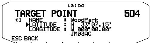
TARGET POINT 4
MARK WAY POINT....4
Mark Way Point List....5
Copying the Mark Way Point to the Target Point....5
Detailed Display of a Mark Waypoint....5
PACKET ...... PACKET-1
PACKET MODE....1
DATA BAND 2
COM PORT SPEED 2
USING EXTERNAL TNC 2
External Data Band 2
DATA Terminal Speed....2
SQC Output Setting....2
TNC COMMANDS LIST 3
APRS ^ ....APRS-
CONNECTING WITH A EXTERNAL GPS RECEIVER OR WEATHER STATION 2
Repeaters are often installed and maintained by radio clubs, sometimes with the cooperation of local businesses involved in the communications industry.
Compared to simplex communication, you can usually transmit over much greater distances by using a repeater. Repeaters are typically located on mountain tops or other elevated locations. They generally operate at higher ERP (Effective Radiated Power) than a typical station. This combination of elevation and high ERP allows communications over considerable distances.
TX: 144.725 MHz
TX tone: 88.5 Hz
RX: 145.325 MHz
TX: 144.725 MHz
TX tone: 88.5 Hz
RX: 145.325 MHz
REPEATER ACCESS
Most repeaters use a receive and transmit frequency pair with a standard or non-standard offset (odd-split). In addition, some repeaters must receive a tone from the transceiver in order to gain access to the repeater. For details, consult your local repeater reference.
■ Selecting an Offset Direction
The offset direction allows your transmit frequency to be higher (+) or lower (−) than the receive frequency.
1 Select your desired band (A or B).
2 Press [F], [SHIFT] to select an offset direction.
• Each time you press [SHIFT], the offset direction changes as follows:
Simplex operation + - Simplex operation
- If you are using an E type transceiver, when operating on the 430 MHz band, the offset direction changes as follows:
If the offset transmit frequency falls outside the allowable range, transmitting is inhibited. Use one of the following methods to bring the transmit frequency within the band limits:
Move the receive frequency further inside the band.
• Change the offset direction.
Note: While using an odd-split memory channel or transmitting, you cannot change the offset direction.
■ Selecting an Offset Frequency
The offset frequency is the value which the transmit frequency will be offset from the receive frequency. The default offset frequency on the 144 MHz band is 600 kHz for all type versions. The default on the 430/440 MHz band is 5 MHz.
1 Select your desired band (A or B).
2 Enter Menu mode and access Menu 400.
3 Set the appropriate offset frequency value.
- The selectable range is from 00.00 MHz to 29.95 MHz, in steps of 50 kHz.
Note: After changing the offset frequency, the new offset frequency will also be used by Automatic Repeater Offset.
■ Activating the Tone Function
To turn the Tone function on:
1 Select your desired band (A or B).
2 Press [TONE] to turn the Tone function ON.
Each press of [TONE] changes the selection as follows:
Tone (T) → CTCSS (CT) → DCS (DCS) → Cross Tone (D↓0 : default) → Off (no display).
The icon appears on the display when the tone function is ON.
Note: When accessing a repeater that requires a 1750 Hz tone, you do not need to activate the Tone function. Simply press the key assigned to the 1750 Hz tone {Menu 906 \~ 911} to transmit the tone.
■ Selecting a Tone Frequency
To select the tone frequency required to access your desired repeater:
1 Turn the Tone function ON.
2 Press [F], [T.SEL].
- The current tone frequency appears on the display. The default frequency is 88.5 Hz.
3 Rotate the Tuning control to select your desired frequency.
• To exit the tone frequency selection, press [ESC].
4 Press any key other than the Tuning control and [ESC] to set the selected frequency.
Note: If you have set up a Memory channel with a tone setting, simply recall the Memory channel instead of setting up the tone frequency every time.
No.
Frequency (Hz)
No.
Frequency (Hz)
No.
Frequency (Hz)
01
67.0
16
110.9
31
186.2
02
69.3
17
114.8
32
192.8
03
71.9
18
118.8
33
203.5
04
74.4
19
123.0
34
206.5
05
77.0
20
127.3
35
210.7
06
79.7
21
131.8
36
218.1
07
82.5
22
136.5
37
225.7
08
85.4
23
141.3
38
229.1
09
88.5
24
146.2
39
233.6
10
91.5
25
151.4
40
241.8
11
94.8
26
156.7
41
250.3
12
97.4
27
162.2
42
254.1
13
100.0
28
167.9
14
103.5
29
173.8
15
107.2
30
179.9
■ Automatic Repeater Offset
This function automatically selects an offset direction and activates the Tone function, according to the frequency that you have selected. To obtain an up-to-date band plan for repeater offset direction, contact your national Amateur Radio association.
1 Enter Menu mode and access Menu 401.
2 Set the ARO to ON.
3 Press [BAND SEL A] to select the A band.
4 Press [VFO] to select VFO mode.
5 Rotate the Tuning control to select your desired frequency.
6 Press [PTT] to start a call.
- You will be transmitting on an offset frequency value determined from your offset setting value and an offset direction depending on your selected frequency. Refer to the settings below for offset directions:
TM-D710GA
Under 145.100 MHz:
No offset(Simplex operation)
145.100 ~ 145.499 MHz:
-600 kHz offset
145.500 ~ 145.999 MHz:
No offset(Simplex operation)
146.000 ~ 146.399 MHz:
+600 kHz offset
146.400 ~ 146.599 MHz:
No offset(Simplex operation)
146.600 ~ 146.999 MHz:
-600 kHz offset
147.000 ~ 147.399 MHz:
+600 kHz offset
147.400 ~ 147.599 MHz:
No offset(Simplex operation)
147.600 ~ 147.999 MHz:
-600 kHz offset
148.000 MHz and higher:
No offset(Simplex operation)
Under 442.000 MHz:
No offset(Simplex operation)
442.000 ~ 444.999 MHz:
+5 MHz offset
445.000 ~ 446.999 MHz:
No offset(Simplex operation)
447.000 ~ 449.999 MHz:
-5 MHz offset
450.000 MHz and higher:
No offset(Simplex operation)
TM-D710GE
Under 145.600 MHz:
No offset(Simplex operation)
145.600 ~ 145.799 MHz:
- 600 KHz offset
145.800 MHz and higher:
No offset(Simplex operation)
TRANSMITTING A 1750 Hz TONE
Most repeaters in Europe require that a transceiver transmit a 1750 Hz tone. On a E type model, simply pressing Microphone [CALL] causes it to transmit a 1750 Hz tone. It is also possible to program [1750] on the front panel as a PF key for transmitting a 1750 Hz tone.
Note: The transceiver continuously transmits a 1750 Hz tone until you release Microphone [CALL] or PF key(1750).
Some repeaters in Europe must receive continuous signals for a certain period of time, following a 1750 Hz tone. This transceiver is also capable of remaining in the transmit mode for 2 seconds after transmitting a 1750 Hz tone.
1 Enter Menu mode and access Menu 402.
2 Set the tone to ON or OFF.
Note: While remaining in the transmit mode, the transceiver does not continuously transmit a 1750 Hz tone.
REVERSE FUNCTION
After setting a separate receive and transmit frequency, you can exchange these frequencies using the Reverse function. This allows you to manually check the strength of signals you receive directly from other stations, while using a repeater. If the station's signal is strong, move to a simplex frequency to continue the contact and free up the repeater.
Press [REV] to turn the Reverse function ON or OFF.
- When the Reverse function is ON, the R icon will appear on the display.
Note:
If the transmit frequency is outside the allowable transmit frequency range when using Reverse, pressing [PTT] will cause an error tone to sound and transmission will be inhibited.
If the receive frequency is outside the receive frequency range when using Reverse, an error tone will sound and Reverse will not operate.
◆ The ARO (Automatic Repeater Offset) will not function when Reverse is ON.
◆ You cannot switch Reverse ON or OFF while transmitting.
AUTOMATIC SIMPLEX CHECKER (ASC)
While using a repeater, ASC periodically monitors the strength of signals you receive directly from the other stations. If the station's signal is strong enough to allow direct contact without a repeater, the R icon blinks.
Press [REV] (1s) to turn the ASC ON.
- When the ASC is ON, the F icon will appear on the display.
While direct contact is possible, without the use of a repeater, the icon will begin blinking.
• To exit ASC, press [REV].
Note:
◆ Pressing [PTT] will cause the F icon to stop blinking.
◆ ASC does not function if you are using simplex operation.
◆ ASC does not function while scanning.
◆ Activating ASC while using Reverse will switch the Reverse function OFF.
If you recall a Memory channel or the Call channel, and those channels are set up with the Reverse function switched ON, the ASC will switch OFF.
◆ You cannot use ASC when the built-in TNC is turned ON.
ASC causes received signals to be momentarily intermitted every 3 seconds.
TONE FREQUENCY ID
This function scans through all tone frequencies to identify the incoming tone frequency on a received signal. You can use this function to find which tone frequency is required by your local repeater.
1 Press [TONE] to switch the Tone function ON.
• The icon appears on the display.
2 Press [F], [T.SEL] (1s) to run the Tone Frequency ID scan.
• The T icon blinks and SCAN appears on the display.
To reverse the scan direction, turn the Tuning control clockwise (upward scan) or counterclockwise (downward scan).
• To quit the function, press [ESC].
When the tone frequency is identified, the identified frequency appears on the display and blinks. Press any key other than the Tuning control while the identified frequency is blinking, to resume scanning.
other
| Metric | Value |
|--------|---------|
| Current | 123.0 |
| iGPS | 440.000 |
3 Press the Tuning control to program the identified frequency in place of the currently set tone frequency.
The Tone function will remain ON. You can press [TONE] to switch the Tone function OFF.
Press [ESC] if you do not want to program the identified frequency.
In Memory channels, you can store frequencies and related data that you often use. Then you need not reprogram the data every time. You can quickly recall a programmed channel by simple operation. A total of 1000 Memory channels are available for bands A and B.
SIMPLEX & REPEATER OR ODD-SPLIT MEMORY CHANNEL?
You can use each memory channel as a simplex & repeater channel or as an odd-split channel. Store only one frequency to use as a simplex & repeater channel or two separate frequencies to use as an odd-split channel. Select either application for each channel depending on the operations you have in mind.
Simplex & repeater channels allow:
Simplex frequency operation
Repeater operation with a standard offset (if an offset direction is stored)
Odd-split channels allow:
• Repeater operation with a non-standard offset
The data listed below can be stored in each Memory channel:
Parameter
Simplex & Repeater
Odd-split
Receive frequency
Yes
Yes
Transmit frequency
Yes
Receive frequency step size
Yes
Yes
Transmit frequency step size
Yes
Offset direction
Yes
No
Tone ON/OFF
Yes
Yes
Tone frequency
Yes
Yes
CTCSS ON/OFF
Yes
Yes
CTCSS frequency
Yes
Yes
DCS ON/OFF
Yes
Yes
DCS code
Yes
Yes
Reverse ON/OFF
Yes
No
Memory channel lockout
Yes
Yes
Memory channel name
Yes
Yes
Modulation/ Demodulation mode
Yes
Yes
STORING SIMPLEX AND STANDARD REPEATER FREQUENCIES
1 Press [VF0] to enter VFO mode.
2 Rotate the Tuning control to select your desired frequency.
- Additionally, you can press the microphone [UP]/[DWN] keys to select a frequency.
3 Set up any additional data desired for the frequency.
- Offset direction, Tone ON/OFF, Tone frequency, CTCSS ON/OFF, CTCSS frequency, DCS ON/OFF, DCS code, etc.
4 Press [F].
• A memory channel number appears.
5 Rotate the Tuning control to select your desired channel number.
When the selected channel number does not have stored data, the “▶” icon appears. When the channel does have stored data, the “▶” icon appears.
Additionally, you can press the microphone [UP]/[DWN] keys to select a channel.
6 Press [M.IN] to store the data in the selected Memory channel.
Note: If you store the data in a Memory channel that already has data stored in it, the old data will be cleared and the new data will be stored.
■ Call Channel Memory (Simplex)
The Call channel can be used to store any frequency and related data that you will recall often. You may want to dedicate the Call channel as an emergency channel within your group.
To store a simplex frequency and related data as the Call channel instead of in a Memory channel, after step 4 (above), press [C.IN].
Note: Storing new data in the Call channel will clear the old data. (The Call channel itself cannot be cleared, but data can be replaced with new data.)
STORING ODD-SPLIT REPEATER FREQUENCIES
Some repeaters use a receive and transmit frequency pair with a non-standard offset. To access those repeaters, store two separate frequencies in a memory channel. You can then operate on those repeaters without changing the offset frequency you stored in the menu.
1 Set up a simplex channel by following steps 1 to 6 of "STORING SIMPLEX AND STANDARD REPEATER FREQUENCIES", above.
2 Press [VFO] to enter VFO mode.
3 Rotate the Tuning control to select your desired transmit frequency.
- Additionally, you can press the microphone [UP]/[DWN] keys to select a frequency.
4 Set up any additional data desired for the transmit frequency.
- Tone ON/OFF, Tone frequency, CTCSS ON/OFF, CTCSS frequency, DCS ON/OFF, DCS code, etc.
5 Press [F].
• A memory channel number appears.
6 Rotate the Tuning control to select your desired channel number.
- Additionally, you can press the microphone [UP]/[DWN] keys to select a channel.
7 Press [PTT], [M.IN] to store the data in the selected Memory channel.
■ Call Channel Memory (Odd-Split)
The Call channel can be used to store any frequency and related data that you will recall often. You may want to dedicate the Call channel as an emergency channel within your group.
To store an odd-split frequency and related data as the Call channel instead of in a Memory channel, after step 6 (above), press [PTT], [C.IN].
Note:
You cannot set the transmission and reception frequencies on different bands.
You cannot set a different frequency step size for the transmission and reception frequencies.
You cannot store the transmit offset status and Reverse status in an odd-split Call channel.
RECALLING A MEMORY CHANNEL
1 Press [MR] to enter Memory Recall mode.
2 Rotate the Tuning control to select your desired Memory channel.
- Additionally, you can press the microphone [UP]/[DWN] keys to select a channel, or you can enter a channel number using the microphone keypad.
■ Memory Recall Method
The transceiver Menu also provides you with the option to recall Memory channels with stored frequencies in your current band, or all Memory channels:
1 Enter Menu mode and access Menu 201.
2 Set the recall method to CURRENT (current band) or ALL BANDS (all bands).
CURRENT allows you to recall only those memory channels that have stored frequencies within the current band. ALL allows you to recall all programmed memory channels.
When the recalled memory channel is an AM channel, you cannot recall on the B band.
1 Press [MR] to enter Memory Recall mode.
2 Rotate the Tuning control to select your desired Memory channel.
- Additionally, you can press the microphone [UP]/[DWN] keys to select a channel, or you can enter a channel number using the microphone keypad.
3 Turn the transceiver power OFF.
4 Press [MR] + Power ON.
• A confirmation message appears on the display.
5 Press the Tuning control to clear the Memory channel.
• To exit without clearing the channel, press [ESC].
NAMING A MEMORY CHANNEL
You can name Memory channels using up to 8 characters. When you recall a named Memory channel, its name appears on the display. Names can be callsigns, repeater names, cities, people, etc.
1 Press [MR] to enter Memory Recall mode.
2 Rotate the Tuning control to select your desired Memory channel.
3 Enter Menu mode and access Menu 200.
4 Enter your desired name for the channel.
Note: You can overwrite a Memory channel name by performing the steps above. You can also clear a Memory channel name by clearing the Memory channel.
MEMORY-TO-VFO TRANSFER
Transferring the contents of a Memory channel or the Call channel to the VFO can be useful if you want to search for other stations or a clear frequency, near the selected Memory channel or Call channel frequency.
1 Press [MR] or [CALL] to enter Memory Recall mode or select the Call channel.
2 Rotate the Tuning control to select your desired channel. (This step is not necessary when selecting the Call channel.)
3 Press [F], [M>V].
The entire contents of the Memory channel or Call channel are copied to the VFO, and VFO mode is selected after the transfer is complete.
When copying a transmit frequency from an odd-split Memory or Call channel, you must first turn the Reverse function ON before pressing [F], [M>V].
CHANNEL DISPLAY FUNCTION
Use this function when you want to use only Memory channels. When this function is switched ON, the transceiver displays only a Memory channel number instead of a frequency.
1 Turn the transceiver power OFF.
2 Press [LOW] + Power ON to turn the channel display ON or OFF.
Note:
◆ If no Memory channels have saved data in them, channel display will not function.
When using Channel Display, you cannot reset the transceiver.
While in Channel Display mode, the transceiver keys function as shown next page:
Key Name
[KEY]
[F], [KEY]
[KEY] (1s)
While Transmitting
[KEY] + Power ON
∅
Power ON/OFF
Power ON/OFF
Power ON/OFF
Power ON/OFF
X
PM
-
-
-
-
-
TNC
-
DX PacketClusters Monitor ON/OFF
-
-
-
CALL
Call mode
-
Call Scan
-
-
VFO
-
-
-
-
-
MR
MR mode
-
Memory Scan
-
-
KEY
-
-
-
-
-
F
Function mode
Exit Function mode
Key Lock
-
Reset
TONE
-
-
-
-
-
REV
Reverse ON/OFF
-
-
-
-
LOW/ MUTE
Change output power
Mute
-
Change output power
Change channel display
PF1
Select the Weather channel (TM-D710GA)
-
-
-
-
PF2
Change control band (default)
-
-
-
-
Tuning control
-
-
Group Scan
-
-
BAND SEL A
A band
-
Change Single/Dual
-
-
BAND SEL B
B band
-
Change Single/Dual
-
-
Programmable Memory (PM) stores virtually all settings currently set on the transceiver. This transceiver provides 5 PM channels to store 5 sets of transceiver configurations. Later, you can quickly recall any one of these channels, depending on the operations you have in mind or the operating environment.
The following programmable settings cannot be stored:
Memory name
• Memory channel lockout
Channel Display mode
Locked-band/ Cross-band Repeater ON/OFF ^1
Repeater mode ^1
Repeater hold ^1
Repeater ID transmit ^1
Registered repeater ID ^1
Wireless remote control ^1
Answer back ^1
Remote control ID ^1
Key lock
• Power on password ^2
• Memory channel/ Call channel/ Program scan memory
^1 TM-D710GA only
^2 Can be set only by using the MCP-6A software.
APPLICATION EXAMPLES
The following are examples of how you might use Programmable Memory. These examples may not represent applications useful to you, but you will understand the flexibility of this function.
Situation: You share your transceiver with other members in your family or club. However, each individual has personal preferences for how they like to set various functions. You have to keep changing many settings each time you use the transceiver.
Solution: Because 5 PM channels are available, up to 5 persons can separately program the transceiver and store their customized environment. Then each person can quickly change to his or her favorite settings, simply by recalling a PM channel. It is too much trouble to change back the settings after somebody else has reconfigured them. So this application may avoid having a feature-rich transceiver but never using many useful features.
Situation: While operating mobile on the way to work every morning, you prefer a silent transceiver that does not interrupt the morning calm. In addition, you feel that a bright display is useless in the sunlight. At night when driving home, you realize the Beep function truly does serve a purpose and you acknowledge it is nice to see a bright display after dark.
Solution: In 2 PM channels, store the same operating data such as frequency, offset, tone, etc, and store different settings for the Display brightness and Beep functions. Then you can quickly recall the best settings for day or night operation.
Situation: You cannot figure out how to exit the current transceiver mode.
Solution: Simply recall PM channel 1, which contains an exact copy of the transceiver default environment. You will not lose the contents of any memory channels.
STORING DATA IN PM CHANNELS
1 Confirm that the following conditions have been satisfied:
• The transceiver is in receive mode.
- Scan is not being used.
• Microphone Control is OFF.
2 Configure the transceiver with your desired settings.
3 Press [F], [P.IN].
- PM channel numbers 1 to 5 appear and blink at the bottom of the display.
other
| Channel | Value |
|---------|---------|
| PTI | 144.000 |
| iGPS | 440.000 |
4 Enter a channel number ([1] to [5]) corresponding to your desired PM channel.
• The settings are stored in the PM channel.
RECALLING PM CHANNELS
1 Press [PM].
- PM channel numbers 1 to 5 and OFF appear on the bottom of the display.
other
| Signal | Value |
|--------|---------|
| PITT | 144.000 |
| CTRL | 12:00 |
| iGPS | 440.000 |
2 Enter a channel number ([1] to [5]) corresponding to your desired PM channel.
• The settings stored in the PM channel are recalled.
• The selected channel number appears on the display.
- When selecting [OFF], the PM channels turn off.
AUTO PM CHANNEL STORE
After you recall a PM channel, this function automatically overwrites the current PM channel with the present operating environment when:
• You recall another PM channel.
- You press [PM].
• You switch the transceiver power OFF.
Follow the steps below to activate the Auto PM storage function.
1 Enter Menu mode and access Menu 922.
2 Set to ON.
Note: If you do not recall a PM channel (1 - 5), Menu No. 922 will not appear on the display.
PM CHANNEL RESET
To reset the PM channels to their default settings:
1 Turn the transceiver power OFF.
2 Press [F] + Power ON.
3 Release [F].
4 Rotate the Tuning control and select PM RESET.
5 Press the Tuning control.
• A confirmation message appears on the display.
6 Press the Tuning control again to reset the PM channels.
Press [BACK] to return to the previous display.
• To exit without resetting the PM channels, press [ESC].
Scan is a useful feature for hands-off monitoring of your favorite frequencies. Becoming comfortable with all types of Scan will increase your operating efficiency.
This transceiver provides the following types of scans:
Scan Type
Scan Range
VFO Scan
Scans all frequencies on the current band.
Memory Scan
Scans all frequencies stored in the Memory channels.
Group Scan
Scans the frequencies in the Memory channels which belong to the group you have specified.
Program Scan
Scans all frequencies within the programmed range, on the current band.
MHz Scan
Scans all frequencies within a 1 MHz range from the originating frequency.
Call Scan
Scans the Call channel as well as the currently selected VFO frequency or Memory channel.
Note:
Adjust the squelch level before using Scan. Selecting a squelch level too low could cause Scan to stop immediately.
While using CTCSS or DCS, Scan stops for any signal received; however, you will hear audio only when the signal contains the same CTCSS tone or DCS code that you selected.
When using S-meter Squelch, Scan stops when the received signal strength matches or exceeds the S-meter setting. Scan resumes 2 seconds after the signal level drops below the S-meter setting.
◆ Pressing and holding [PTT] causes Scan to temporarily stop if it is functioning on a non TX band.
◆ Starting Scan switches the Automatic Simplex Checker OFF.
SELECTING A SCAN RESUME METHOD
The transceiver stops scanning at a frequency or Memory channel on which a signal is detected. It then continues scanning according to which resume mode you have selected. You can choose one of the following modes. The default is Time-operated mode.
• Time-Operated mode
The transceiver remains on a busy frequency or Memory channel for approximately 5 seconds, and then continues to scan even if the signal is still present.
• Carrier-Operated mode
The transceiver remains on a busy frequency or Memory channel until the signal drops out. There is a 2 second delay between signal drop-out and scan resumption.
- Seek mode
The transceiver remains on a busy frequency or Memory channel even after the signal drops out and does not automatically resume scanning.
Note: To temporarily stop scanning and monitor weak signals, press the microphone PF key assigned to the Monitor function. Press the PF key again to resume scanning.
1 Enter Menu mode and access Menu 913.
2 Set the Scan Resume mode to TIME (Time-Operated), CARRIER (Carrier-Operated) or SEEK.
■ Time-Operate Resume Time
Set the hold time for the Time-Operate scan method. When a signal is received, scan will pause at that frequency for the duration of the hold time you set. When the set time elapses, scan will resume (even if the signal is still being received).
1 Enter Menu mode and access Menu 914.
2 Set the resume time to 1 \~ 10 sec.
■ Carrier-Operated Resume Time
Set the hold time for the Carrier-Operate scan method. When a signal is received, scan will pause at that frequency. When the signal stops, scan will resume after the duration of the hold time you set.
1 Enter Menu mode and access Menu 915.
2 Set the resume time to 1 \~ 10 sec.
VFO Scan monitors all frequencies tunable on the band, using the current frequency step size.
1 Select your desired band.
2 Press [VFO] (1s).
Scan starts at the current frequency.
• The 1 MHz decimal blinks while scanning is in progress.
To reverse the scan direction, turn the Tuning control clockwise (upward scan) or counterclockwise (downward scan). You can also press microphone [UP]/ [DWN].
3 To quit VFO Scan, press [VFO] again.
MEMORY SCAN
Use Memory Scan to monitor all Memory channels programmed with frequency data.
1 Select your desired band.
2 Press [MR] (1s).
- Scan starts at the current frequency.
• The 1 MHz decimal blinks while scanning is in progress.
- To reverse the scan direction, turn the Tuning control clockwise (upward scan) or counterclockwise (downward scan). You can also press microphone [UP]/ [DWN].
3 To quit Memory Scan, press [MR] again.
Note:
◆ At least 2 Memory channels must contain data and must not be locked out of scan.
◆ The L0/U0 to L9/U9 Memory channels will not be scanned.
You can also start Memory Scan when in Channel Display mode. While Scan is paused on a channel, the channel number blinks.
■ Locking Out a Memory Channel
You can select Memory channels that you prefer not to monitor while scanning.
1 Press [MR], then rotate the Tuning control to select your desired channel.
2 Enter Menu mode and access Menu 202.
3 Set the lockout to ON to lock the channel out of the scanning sequence.
• To cancel lockout, set the lockout to OFF.
- The ★ icon appears on the display for a channel that has been locked out.
Note: The L0/U0 to L9/U9 Memory channels cannot be locked out.
GROUP SCAN
For the purpose of Group Scan, the 1000 Memory channels are divided into 10 groups, with each group containing 100 channels. Group Scan monitors only the 100 channels which belong to the specific group you are scanning. The channels are grouped as follows:
Memory Group
Channel Range
Memory Group
Channel Range
0
0 ~ 99
5
500 ~ 599
1
100 ~ 199
6
600 ~ 699
2
200 ~ 299
7
700 ~ 799
3
300 ~ 399
8
800 ~ 899
4
400 ~ 499
9
900 ~ 999
1 Press [MR], then rotate the Tuning control to select a channel in your desired group.
2 Press the Tuning control (1s).
- Scan starts at the current channel.
• The 1 MHz decimal blinks while scanning is in progress.
- To reverse the scan direction, turn the Tuning control clockwise (upward scan) or counterclockwise (downward scan). You can also press microphone [UP]/ [DWN].
3 To quit Group Scan, press the Tuning control again.
Note:
◆ At least 2 Memory channels in the selected group must contain data and must not be locked out of scan.
You can also start Memory Scan when in Channel Display mode. While Scan is paused on a channel, the channel number blinks.
■ Memory Group Link
Memory Group Link provides you with the ability to link 2 or more Memory channel groups together to act as a single group when scanning. You can link up to 10 separate groups together, or even add multiple instances of the same group to the group link, to ensure that one group is scanned more often than the other groups.
1 Enter Menu mode and access Menu 203.
2 Press the Tuning control.
• The cursor will begin blinking.
3 Rotate the Tuning control to select a group to link.
4 Press the Tuning control to set the group and move the cursor to the right.
- Press [←] to move the cursor back or [→] to move the cursor to the right.
5 Repeat steps 3 and 4 to link additional groups together.
6 When you have entered your desired groups, press [→] to move the cursor to the right, then press the Tuning control to complete the entry and exit Menu mode.
• You can insert a character by pressing [INS].
• You can delete the selected character by pressing [CLR].
- If you have entered the maximum of 6 groups, simply press the Tuning control to complete the entry and exit Menu mode.
Program Scan is identical to VFO Scan except that you select a frequency range for the scan.
■ Setting Scan Limits
You can store up to 10 scan ranges in Memory channels L0/U0 to L9/U9.
1 Press [VFO].
2 Select your desired band.
3 Rotate the Tuning control to select your desired frequency for the lower limit.
4 Press [F].
• A memory channel number appears and blinks.
5 Rotate the Tuning control to select a channel from L0 to L9.
6 Press [M.IN] to set the channel number.
• The lower limit is stored in the channel.
7 Rotate the Tuning control to select your desired frequency for the lower limit.
8 Press [F].
9 Rotate the Tuning control to select a matching channel number from U0 to U9.
- For example, if you select channel L3 in step 5, select channel U3 here.
10 Press [M.IN] to set the channel number.
• The upper limit is stored in the channel.
- To confirm the stored scan limits, press [MR], then select the L and U channels.
Note:
◆ The lower limit must be lower in frequency than the upper limit.
◆ The lower and upper frequency step sizes must be equal.
◆ The lower and upper limits must be selected on the same band.
■ Using Program Scan
1 Select your desired band.
2 Press [VFO].
3 Rotate the Tuning control to select a frequency within your desired scan range.
4 Press [VFO] (1s).
Scan starts at the current frequency.
• The 1 MHz decimal blinks while scanning is in progress.
To reverse the scan direction, turn the Tuning control clockwise (upward scan) or counterclockwise (downward scan). You can also press microphone [UP]/ [DWN].
5 To quit Program Scan, press [VFO] again.
Note:
◆ If the step size differs between the lower limit and upper limit, VFO scan will begin instead of Program Scan.
◆ If the current VFO frequency is within more than one Program Scan range, the range stored in the smallest channel number is used.
MHz SCAN
MHz Scan monitors a 1 MHz segment of the band, using the current frequency step size. The current 1 MHz digit determines the limits of the scan. For example, if the current frequency is 145.400 MHz, then the scan range would be from 145.000 MHz to 145.995 MHz (the exact upper limit depends on the current frequency step size).
1 Select your desired band.
2 Press [VFO].
3 Rotate the Tuning control to select a frequency within your desired 1 MHz range.
4 Press and hold the Tuning control for 1 second to start scanning.
Scan starts at the current frequency.
• The 1 MHz decimal blinks while scanning is in progress.
To reverse the scan direction, turn the Tuning control clockwise (upward scan) or counterclockwise (downward scan). You can also press microphone [UP]/ [DWN].
5 To quit MHz Scan, press the Tuning control again.
CALL SCAN
Use Call Scan to monitor both the Call channel and either the currently selected VFO frequency or the currently selected Memory channel.
1 Select your desired VFO frequency or Memory channel.
2 Press [CALL] (1s) to start Call Scan.
• The 1 MHz decimal blinks while scanning is in progress.
- When scanning a Memory channel, the Call channel on the same band as the selected Memory channel is used for scan.
3 To quit Call Scan, press [CALL] again.
Note: The Memory channel selected is scanned even if it has been locked out of scan.
VISUAL SCAN
While you are receiving, Visual Scan allows you to monitor frequencies near the current operating frequency. Visual Scan graphically and simultaneously shows how all frequencies in the selected range are busy. You will see up to 21 segments, for each channel, that represent 7 S-meter levels (3 segments per level).
Determine the scan range by selecting the center frequency and the number of channels. The default number of channels is 61.
■ Selecting the Number of Channels
1 Enter Menu mode and access Menu 916.
2 Set the number of channels to MODE 1 (31ch), MODE 2 (61ch), MODE 3 (91ch), or MODE 4 (181ch).
■ Using Visual Scan
1 Select your desired band.
2 Rotate the Tuning control select the operating frequency.
• This frequency will be used as the center frequency.
3 Press [F], [VISUAL] to start Visual Scan.
bar
| Category | Value |
| -------- | ------- |
| PTT | 144.000 |
| CTRL | 144.000 |
| H D | 144.000 |
| FM | 144.000 |
| BUSY | 144.000 |
| ESC | 144.000 |
| RESET | 144.000 |
| PAUSE SET| 144.000 |
| ESC | 144.000 |
- To halt Scan, press [PAUSE]. "PAUSE" appears and blinks. Press [PAUSE] again to resume.
4 To change the operating frequency, rotate the Tuning control.
The displayed frequency changes and the cursor moves.
Press [SET] to use the changed operating frequency as the center frequency.
Press [RESET] to restore the previous operating frequency.
5 To exit Visual Scan, press [ESC].
Note:
◆ You cannot use the Visual Scan Function under the following circumstances:
- When the APRS/NAVITRA or Packet mode is turned ON.
- When only 1 channel has been stored in the memory channels.
- When using Weather Alert (K models only).
◆ If you start Visual Scan in Memory Recall mode, the memory channel frequencies will be scanned.
◆ If you start Visual Scan after recalling the Call channel, the Call channel frequency will be used as the center frequency.
If the frequency range specified for Program Scan or Program VFO is narrower than the range specified for Visual Scan, the range for Program Scan or VFO will be used for Visual Scan.
◆ Visual Scan stops while transmitting.
If you start Visual Scan in one of the following conditions, you cannot receive in the current operating frequency. To use this frequency, press [PAUSE] to halt Scan.
• Memory Recall or Call Channel mode.
- A frequency in the 118, 220, 300, or 1200 MHz band was selected in VFO mode.
◆ Depending on the transceiver conditions, Visual Scan and the conventional S-meter may indicate different signal strength levels.
CTCSS
You may sometimes want to hear calls only from specific persons. The Continuous Tone Coded Squelch System (CTCSS) allows you to ignore (not hear) unwanted calls from other persons who are using the same frequency. To do so, select the same CTCSS tone as selected by the other persons in your group. A CTCSS tone is subaudible and is selectable from among 42 tone frequencies.
DCS
Digital Coded Squelch (DCS) is another application which allows you to ignore (not hear) unwanted calls. It functions the same way as CTCSS. The only differences are the encode/ decode method and the number of selectable codes. For DCS, you can select from 104 different codes.
Note: CTCSS/ DCS does not cause your conversation to be private. It only relieves you from listening to unwanted conversations.
USING CTCSS
1 Select your desired band.
2 Press [TONE] 2 times to activate the CTCSS function.
The CT icon appears on the display when the CTCSS function is ON.
Tone (T) → CTCSS (CT) → DCS (DCS) → Cross Tone (D,0: default) → Off (no display).
3 Press [F], [T.SEL].
- The current CTCSS frequency appears on the display and blinks.
scatter
| Label | Value |
|-------|---------|
| PTT | 88.5 |
| CTRL CT | 121.00 |
| H | 9 |
| FM | 440.000 |
4 Rotate the Tuning control to select your desired CTCSS frequency.
• Refer to the table below for the available frequencies.
• To exit the CTCSS frequency selection, press [ESC].
5 Press any key other than the Tuning control and [ESC] to complete the setting.
6 When you are called: The transceiver squelch opens only when the selected CTCSS tone is received.
When you make a call: Press and hold [PTT], then speak into the microphone.
- To cancel CTCSS, press [TONE] until CT no longer appears on the display.
5 Enter a frequency reference number (01 \~ 42) using the microphone keypad.
- Refer to the table below for frequencies and their reference numbers.
No.
Frequency (Hz)
No.
Frequency (Hz)
No.
Frequency (Hz)
01
67.0
16
110.9
31
186.2
02
69.3
17
114.8
32
192.8
03
71.9
18
118.8
33
203.5
04
74.4
19
123.0
34
206.5
05
77.0
20
127.3
35
210.7
06
79.7
21
131.8
36
218.1
07
82.5
22
136.5
37
225.7
08
85.4
23
141.3
38
229.1
09
88.5
24
146.2
39
233.6
10
91.5
25
151.4
40
241.8
11
94.8
26
156.7
41
250.3
12
97.4
27
162.2
42
254.1
13
100.0
28
167.9
14
103.5
29
173.8
15
107.2
30
179.9
You can also select a CTCSS frequency by using the microphone:
1 Select your desired band.
2 Press [TONE] 2 times to activate the CTCSS function.
The CT icon appears on the display when the CTCSS function is ON.
Each press of [TONE] changes the selection as follows:
Tone (T) → CTCSS (CT) → DCS (DCS) → Cross Tone (D,0: default) → Off (no display).
3 Press [F], [T.SEL].
- The current CTCSS frequency appears on the display and blinks.
4 Press the key programmed as [ENTER].
This function scans through all CTCSS frequencies to identify the incoming CTCSS frequency on a received signal. You may find this useful when you cannot recall the CTCSS frequency that the other persons in your group are using.
1 Press [TONE] 2 times to activate the CTCSS function.
The CT icon appears on the display when the CTCSS function is ON.
Each press of [TONE] changes the selection as follows:
Tone (T) → CTCSS (CT) → DCS (DCS) → Cross Tone (D,0: default) → Off (no display).
2 Press [F], [T.SEL] (1s).
The CT icon blinks and "SCAN" appears on the display.
Scan starts when a signal is received.
To reverse the scan direction, turn the Tuning control clockwise (upward scan) or counterclockwise (downward scan). You can also press microphone [UP]/ [DWN].
• To quit the scan, press [ESC].
When a CTCSS frequency is identified, the identified frequency appears on the display and blinks.
3 Press the Tuning control to program the identified frequency in place of the currently set CTCSS frequency.
The CTCSS function will remain ON. To cancel CTCSS, press [TONE] until CT no longer appears on the display.
Press [ESC] if you do not want to program the identified frequency.
Rotate the Tuning control while an identified frequency is blinking, to resume scanning.
USING DCS
1 Select your desired band.
2 Press [TONE] 3 times to activate the DCS function.
The DCS icon appears on the display when the DCS function is ON.
Each press of [TONE] changes the selection as follows:
Tone (T) → CTCSS (CT) → DCS (DCS) → Cross Tone (D:0:default) → Off (no display).
3 Press [F], [T.SEL].
• The current DCS code appears on the display and blinks.
4 Rotate the Tuning control to select your desired DCS code.
• Refer to the table below for the available codes.
• To exit the DCS code selection, press [ESC].
5 Press any key other than the Tuning control and [ESC] to complete the setting.
6 When you are called: The transceiver squelch opens only when the selected DCS code is received.
When you make a call: Press and hold [PTT], then speak into the microphone.
- To cancel DCS, press [TONE] until DCS no longer appears on the display.
You can also select a DCS code by using the microphone:
1 Select your desired band.
2 Press [TONE] 3 times to activate the DCS function.
The DCS icon appears on the display when the DCS function is ON.
• Each press of [TONE] changes the selection as follows:
$$
\begin{array}{l}\text { Tone } (\mathbf {T}) \rightarrow \text { CTCSS } (\mathbf {C T}) \rightarrow \text { DCS } (\mathbf {D C S}) \rightarrow \text { Cross Tone } (\mathbf {D A O}:\\text { default }) \rightarrow \text { Off (no display) }.\end{array}
$$
3 Press [F], [T.SEL].
• The current DCS code appears on the display and blinks.
4 Press the key programmed as [ENTER].
5 Enter your desired DCS code using the microphone keypad.
• Refer to the table below for DCS codes.
DCS Code
023
025
026
031
032
036
043
047
051
053
054
065
071
072
073
074
114
115
116
122
125
131
132
134
143
145
152
155
156
162
165
172
174
205
212
223
225
226
243
244
245
246
251
252
255
261
263
265
266
271
274
306
311
315
325
331
332
343
346
351
356
364
365
371
411
412
413
423
431
432
445
446
452
454
455
462
464
465
466
503
506
516
523
526
532
546
565
606
612
624
627
631
632
654
662
664
703
712
723
731
732
734
743
754
DCS CODE SCAN
This function scans through all DCS codes to identify the incoming DCS code on a received signal. You may find it useful when you cannot recall the DCS code that the other persons in your group are using.
1 Press [TONE] 3 times to activate the DCS function.
The DCS icon appears on the display when the DCS function is ON.
Each press of [TONE] changes the selection as follows:
Tone (T) → CTCSS (CT) → DCS (DCS) → Cross Tone (DAD0: default) → Off (no display).
2 Press [F], [T.SEL] (1s).
The DCS icon blinks and "SCAN" appears on the display.
Scan starts when a signal is received.
To reverse the scan direction, turn the Tuning control clockwise (upward scan) or counterclockwise (downward scan). You can also press microphone [UP]/ [DWN].
• To quit the scan, press [ESC].
When a DCS code is identified, the identified code appears on the display and blinks.
scatter
| Label | Value |
|---|---|
| 12:00 FM | 440.000 |
| iGPS FM | 440.000 |
| ESC | 223 |
3 Press the Tuning control to program the identified code in place of the currently set DCS code.
The DCS function will remain ON. To cancel DCS, press [TONE] until DCS no longer appears on the display.
Press [ESC] if you do not want to program the identified code.
Rotate the Tuning control while an identified code is blinking, to resume scanning.
USING CROSS TONE
You can set separate signaling types by TX and RX for when you access a repeater that uses different Encode/ decode signaling.
To turn the Cross Tone function On:
Press [TONE] 4 times to activate the Cross Tone function.
- The “☐☐” (default) icon appears on the display when the Cross Tone function is On.
- Each press of [TONE] changes the selection as follows:
Tone (T) → CTCSS (CT) → DCS (DCS) → Cross Tone (D,0: default) → Off (no display).
■ Selecting a Cross Tone mode
To select the cross tone/code frequency required to access your desired repeater:
1 Turn the Cross Tone function On.
2 Press [F], [T.SEL].
• The Cross Tone setting appears on the display.
3 Rotate the Tuning control to select your desired Cross Tone setting.
Setting
Encode
Decode
Icon
DCS OFF
DCS
off
D↓O
TO DCS
Tone
DCS
T↓D
DCS CT
DCS
CTCSS
D↓C
TO CT
Tone
CTCSS
T↓C
• To exit the Cross Tone setting selection, press [ESC].
4 Press any key other than the Tuning control and [ESC] to complete the setting.
DUAL TONE MULTI-FREQUENCY (DTMF)
The keys on the microphone keypad function as DTMF keys; the 12 keys found on a push-button telephone plus 4 additional keys (A, B, C, D). This transceiver provides 10 dedicated memory channels. You can store a DTMF code with up to 16 digits.
Some repeaters in the U.S.A. and Canada offer a service called Autopatch. You can access the public telephone network via such a repeater by sending DTMF tones. For further information, consult your local repeater reference.
MANUAL DIALING
Manual Dialing requires only two steps to send DTMF tones.
1 Press and hold the microphone [PTT].
2 Press the keys in sequence on the keypad to send DTMF tones.
• The corresponding DTMF tones are transmitted.
- If the DTMF Hold function is activated, you need not hold down [PTT] while pressing keys. After transmitting the first tone (by pressing [PTT] and the first key), pressing additional keys will keep the transceiver in transmit mode for 2 seconds.
Frequency (Hz)
1209
1336
1447
1633
697
[1]
[2]
[3]
[A]
770
[4]
[5]
[6]
[B]
852
[7]
[8]
[9]
[C]
941
[*]
[0]
[#]
[D]
DTMF Hold
Activate this function to remain in transmit mode, after beginning to press keys when making a call.
1 Enter Menu mode and access Menu 300.
2 Set DTMF Hold to ON to continue transmitting when pressing keys.
- Set this menu to OFF to stop the 2 second continuous transmission.
AUTOMATIC DIALER
There are 10 dedicated DTMF Memory channels available to store DTMF codes. You can store up to 16 digits in each channel.
■ Storing a DTMF Code in Memory
1 Enter Menu mode and access Menu 301.
2 Rotate the Tuning control to select a channel number.
3 Press the Tuning control to set the selected channel number.
• The name entry display appears.
4 Enter a name for the channel, the press the Tuning control to set it.
• The code entry display appears.
5 Enter a DTMF code for the channel, then press the Tuning control to set it.
- When a space is entered, it becomes a “Pause” code.
■ Transmitting Stored DTMF Codes
1 Press and hold the microphone [PTT].
2 While transmitting, press the Tuning control.
- The last called DTMF Memory channel name and number appear on the display. If no name has been saved for the channel, the DTMF code appears.
3 While still transmitting, rotate the Tuning control to select your desired DTMF Memory channel, then press the Tuning control to set the channel.
Additionally, you can press a DTMF key corresponding to your desired channel ([0] \~ [9]) to select the channel and begin transmission.
The stored DTMF code scrolls across the display and is transmitted.
The code will be transmitted even if you release [PTT] before the entire code has scrolled across the display.
If no DTMF code is stored in the selected channel, the frequency display is restored.
■ Selecting a Transmit Speed
Some repeaters may not respond correctly if a DTMF code is transmitted at fast speed. If this happens, change the DTMF code transmission speed from FAST (default) to SLOW.
1 Enter Menu mode and access Menu 302.
2 Set the speed to FAST or SLOW.
■ Selecting a Pause Duration
You can change the pause duration stored in DTMF Memory channels; the default is 500 msec.
1 Enter Menu mode and access Menu 303.
2 Select a speed (in msec) from the available list: 100/250/500/750/1000/1500/2000.
DTMF KEY LOCK
This function will lock the DTMF transmission keys so that they will not transmit if they are accidentally pressed. To lock the DTMF keys, turn this function ON.
1 Enter Menu mode and access Menu 304.
2 Set the key lock to ON or OFF.
WHAT IS EchoLink?
EchoLink allows you to communicate with other amateur radio stations over the internet, using VoIP (voice-over-IP) technology. The EchoLink software program allows worldwide connections to be made between stations, or from computer to station, greatly enhancing your communications capabilities.
To use EchoLink, you must register using your callsign on their website and download the EchoLink software program (free of charge). Refer to the website for PC hardware and other requirements.
Official EchoLink Website: http://www.echolink.org
Note: EchoLink is a registered trademark of Synergenics, LLC.
STORING EchoLink MEMORY
There are 10 dedicated EchoLink DTMF Memory channels available. You can store up to 8 digits in each channel.
1 Enter Menu mode and access Menu 204.
2 Rotate the Tuning control to select an EchoLink channel number from EL0 \~ EL9.
3 Press the Tuning control to set the selected channel number.
• The name entry display appears.
4 Enter the name for the channel, then press the Tuning control to set it.
- The callsign and conference name (for board rooms that can do round QSO) of the other station which is connected via EchoLink, or the control command name, etc., are entered into the EchoLink memory name.
• The code entry display appears.
5 Enter a DTMF code for the channel, then press the Tuning control to set it.
- The node number of the other station and conference which are connected via EchoLink, or the DTMF code of the control command, etc., are entered into the EchoLink code.
■ Transmitting EchoLink Memory
1 Press and hold the microphone [PTT].
2 While transmitting, press the Tuning control.
- The last called EchoLink DTMF Memory channel name and number appears on the display.
3 While still transmitting, rotate the Tuning control to select your desired EchoLink Memory channel, then press the Tuning control to set the channel.
- The stored code scrolls across the display and is transmitted.
Note:
In step 2, press the microphone [C] key before pressing the Tuning control, to transmit the converted DTMF code of the EchoLink “Connect by Call” function. (example: JA1YKX)
“C” “51 21 10 93 52 92 #” (# is automatically added to the end of the DTMF code)
In step 2, press the microphone [0] [7] keys before pressing the Tuning control, to transmit the converted DTMF code of the EchoLink "Query by Call" function. (example: JA1YKX)
"0" "7" "51 21 10 93 52 92 #" (# is automatically added to the end of the DTMF code)
When only the EchoLink memory name has been registered, the EchoLink "Connect Call" function transmits the converted DTMF code. (example: JA1YKX)
"C 51 21 10 93 52 92 #" (C is automatically added to the beginning of the DTMF code and # is automatically added to the end)
◆ Callsign/ DTMF Code Conversion Table
When a character other than an alphanumeric character is used (such as “-” and “/”), the DTMF conversion stops at the character before that non-standard character.
1
2
3
4
5
6
7
8
9
0
0
1
2
3
4
5
6
7
8
9
0
1
Q
A
D
G
J
M
P
T
W
2
Z
B
E
H
K
N
R
U
X
3
C
F
I
L
O
S
V
Y
■ Selecting a Transmit Speed
Some repeaters may not respond correctly if a code is transmitted at fast speed. If this happens, change the EchoLink transmission speed from FAST (default) to SLOW.
1 Enter Menu mode and access Menu 205.
2 Set the speed to FAST or SLOW.
SETTING UP EchoLink Sysop MODE
Connect the TM-D710G to a personal computer to use the system as a node station for EchoLink relaying.
When connecting to a personal computer and using the EchoLink Sysop mode, the hard flow control operation RTS and CTS computer terminals operate the same as and are changed with the SQC (squelch control signal output to the computer) and PKS (transmit control signal input from the computer) data terminals.
The current band becomes the same as the data band which is selected in menu No. 918 regardless of the transmission band and operation band.
Use the PG-5H (interface cable kit) when connecting to a personal computer.
flowchart
graph TD
    A["Data communications cable"] --> B["To PC audio terminal"]
    A --> C["Pink: To microphone input terminal"]
    A --> D["Green: To line out terminal"]
    E["Serial communications cable"] --> F["To PC 9-pin D-SUB terminal"]
    G["Data/PC"] --> H["2 SP 1"]
1 Turn the transceiver power OFF.
2 Press [PF2] + Power ON to turn EchoLink Sysop Mode ON.
The icon appears on the display when EchoLink Sysop mode is ON.
When the audio signal is output to the PC side, the 📄 icon blinks.
- To turn EchoLink Sysop Mode OFF, press [PF2] + Power ON again.
EchoLink Sysop Mode ON
PC terminal
PC
TxD
→
RxD
RxD
←
TxD
SQC
→
CTS
PKS
←
RTS
GND
⇔
GND
EchoLink Sysop Mode OFF
PC terminal
PC
TxD
→
RxD
RxD
←
TxD
RTS
→
CTS
CTS
←
RTS
GND
↔
GND
Note:
When using EchoLink Sysop mode, perform the following settings (1) \~ (4).
(1) Set the SQC output setting (Menu No. 921) to "SQL".
(2) When unnecessary noise signals, etc., are sent from the link station to the internet while CTCSS and DCS are active, use can verify the usage condition of the operating frequency by setting "EchoLink RX Monitor" ([Edit] > [Menu] > [Transmit/Receive]) via the MCP-6A to "Busy Only".
Because of this, when EchoLink Sysop mode is ON, all received signals on the DATA band are output from the speaker irregularness of a matching CTCSS or DCS signal.
(Voice signals are output from the DATA terminal only when the CTCSS or DCS signals match.)
(3) To avoid having the EchoLink software detecting a busy state even when the transceiver power is turned OFF, set the "SQC Output Logic" ([Edit] > [Data Terminal]) via the MCP-6A to "High".
(When performing this setting, ensure that the EchoLink's software "Invert Sense" setting in the RX Ctrl tab of the Sysop Setup window is not checked.)
(4) When the audio level adjustment range on your personal computer is insufficient, adjust the AF output level "PR1 Pin Output Level" ([Edit] > [Data Terminal]) and AF input sensitivity "PKD Pin Input Level" ([Edit] > [Data Terminal]) of the transceiver via the MCP-6A. Adjustments can be made in steps of 6dB.
◆ The settings in numbers 2 \~ 4 (above) can be performed only using a MCP-6A.
When EchoLink Sysop mode is ON, it cannot communicate with the MCP-6A. When using the MCP-6A, be sure to turn EchoLink Sysop mode OFF.
SELECTING AN OUTPUT POWER
It is a good idea to select lower transmit power if communications is still reliable. This lowers the risk of interfering with others on the band. When operating from battery power, you will enjoy more operating time before a recharge is necessary.
Press [LOW] to select high (H), medium (M), or low (L) power.
• You can program different power settings for bands A and B.
Note: When the transceiver overheats because of ambient high temperature or continuous transmission, the protective circuit may function to lower transmit output power.
MASKING A BAND
If you have no plans to use band A or B, you can hide the frequency display on the unused band. This saves power consumption and makes it simpler to read the information you need.
1 Turn the transceiver power OFF.
2 Press the left or right [BAND SEL] + Power ON.
• The band mask display appears.
3 Rotate the Tuning control to select the band you want to hide (or return to normal).
4 Press the Tuning control to set the selected band.
5 Rotate the Tuning control to set the band to select USE or MASK.
- USE allows you to see and use the band as normal. MASK hides the band on the display.
6 Press the Tuning control to set the selection.
7 Press the [ESC] to exit.
Note: You cannot operate the masked band nor use it to receive or transmit.
KEY BEEP
You can turn the transceiver beep function ON or OFF as desired.
1 Enter Menu mode and access Menu 000.
2 Turn the beep function ON or OFF.
- Even with the beep function turned OFF, the transceiver will emit a beep tone under the following conditions:
1) When Auto Power Off is activated, the transceiver will beep 1 minute before the power turns off.
2) After transmitting for the maximum time duration according to the Time-out Timer, the transceiver will beep.
■ Beep Volume
Each time you press a key, the beep tone will sound. If you have left the beep function turned ON, you may wish to adjust the volume level of the beep.
1 Enter Menu mode and access Menu 001.
2 Set the beep volume to a level from 1 to 7.
• The default is level 5.
EXTERNAL SPEAKER CONFIGURATION
This transceiver has two speaker jacks for external speakers, as well as an internal speaker. You can enjoy a variety of speaker configurations by using one or two external speakers. Received signals on bands A and B are output depending on how you want the internal and/or external speakers to function.
1 Enter Menu mode and access Menu 002.
2 Set the speaker mode to MODE 1 or MODE 2.
- Refer to the table below for configurations based on the mode selected.
Mode
Speaker Setup
Band Output
Internal Speaker
External SP1
External SP2
MODE 1
None
A, B
-
-
SP1 only
x
A, B
-
SP2 only
A
-
B
SP1, SP2
x
A
B
MODE 2
None
A, B
-
-
SP1 only
x
A, B
-
SP2 only
B
-
A
SP1, SP2
x
B
A
PROGRAMMABLE VFO
If you always check frequencies within a certain range, you can set upper and lower limits for frequencies that are selectable. For example, if you select 144 MHz for the lower limit and 145 MHz for the upper limit, the tunable range will be from 144.000 MHz to 145.995 MHz.
1 Select your desired VFO frequency.
2 Enter Menu mode and access Menu 100.
(Example: E type)
3 Press the Tuning control.
• The lower frequency limit blinks.
4 Rotate the Tuning control to select your desired lower frequency limit, then press the Tuning control to set the selected value.
• The upper frequency limit blinks.
5 Rotate the Tuning control to select your desired upper frequency limit, then press the Tuning control to set the selected value.
6 Press [ESC] to exit Menu mode.
Note: You cannot program the 100 kHz and subsequent digits. The exact 100 kHz and subsequent digits of the upper limit depend on the frequency step size you are using.
CHANGING THE FREQUENCY STEP SIZE
Choosing the correct frequency step size is essential in selecting your exact frequency. The default step size on the 144 MHz band is 5 kHz (TM-D710GA) or 12.5 kHz (TM-D710GE). The default on the 430/440 MHz band is 25 kHz.
1 Press the left or right [BAND SEL] to select band A or B, then press [VFO].
2 Enter Menu mode and access Menu 101.
3 Set the step size to 5.0*, 6.25*, or 8.33 kHz (118 MHz band only) or to 10.0, 12.5, 15.0*, 20.0, 25.0, 30.0, 50.0, or 100.0 kHz.
* These step sizes are not available for the 1200 MHz band.
Note: Changing between step sizes may correct the displayed frequency. For example, if
144.995 MHz is displayed with a 5 kHz step size selected, changing to a 12.5
kHz step size corrects the displayed frequency to 144.9875 MHz.
SWITCHING FM/AM MODE
This transceiver is also capable of receiving (not transmitting) in AM on band A. The default mode on the 118 MHz band is AM while the default on the 144, 220, 300, or 430/440 MHz band is FM.
1 Enter Menu mode and access Menu 102.
2 Set the mode to AM, FM, or NFM.
Note: You cannot switch between FM and AM to receive on band B.
ADVANCED INTERCEPT POINT (AIP)
The VHF/UHF band is often crowded in urban areas. AIP helps eliminate interference and reduce audio distortion caused by inter modulation. You can use this function only while operating on the VHF/UHF band.
1 Enter Menu mode and access Menu 103 (VHF.AIP) and/or Menu 104 (UHF.AIP).
2 Set the AIP to ON or OFF.
S-METER SQUELCH
S-meter Squelch causes the squelch to open only when a signal with the same or greater strength than the S-meter setting is received. This function relieves you from constantly resetting the squelch when receiving weak stations that you have no interest in.
1 Enter Menu mode and access Menu 105.
2 Set the S-Meter squelch to ON or OFF.
3 To select the desired S-meter setting, rotate the left (band A) or right (band B) SQL control depending on which band you have selected.
- The squelch will open only at the level you have selected (for example, level 9).
■ Squelch Hang-up Time
When using S-meter Squelch, you may want to adjust the time interval between when the received signals drop and when the squelch closes.
1 Enter Menu mode and access Menu 106.
2 Set the hang-up time to 125, 250 or 500 ms, or OFF.
SPEAKER MUTE
While receiving or transmitting on the TX band, you may not want to hear audio received on the other band. Use this function to mute the speaker allocated to that band (not the TX band).
While receiving, press [F], [MUTE] to switch the mute function ON or OFF.
• The MUTE icon appears on the display when the function is ON.
■ Mute Hang-up Time
When using Speaker Mute, you may want to adjust the time interval between when you receive a signal and when the speaker is muted.
1 Enter Menu mode and access Menu 107.
2 Set the hang-up time to 125, 250, 500, 750, or 1000 ms.
BEAT SHIFT
Since the transceiver uses a microprocessor to control various transceiver functions, the CPU clock oscillator's harmonics or image may appear on some spots of the reception frequencies. In this case, we recommend you turn the Beat Shift function ON.
1 Enter Menu mode and access Menu 108.
2 Set the Beat Shift to ON or OFF.
TIME-OUT TIMER (TOT)
It is sometimes necessary or desirable to restrict a single transmission to a specific maximum time. You may use this function to prevent repeater time-outs when accessing repeaters, or to conserve battery power.
When TOT times out (default is 10 minutes), the transceiver generates beeps and automatically returns to receive mode. To resume transmitting, release and then press the microphone [PTT] again.
1 Enter Menu mode and access Menu 109.
2 Set the timer to 3, 5, or 10 minutes.
MICROPHONE SENSITIVITY
The input level to the microphone can be configured.
1 Enter Menu mode and access Menu 110.
2 Set the Microphone Sensitivity to HIGH, MEDIUM or LOW.
Note: The higher the input level to the microphone is configured, the easier to gain the surrounded sounds.
POWER ON MESSAGE
Each time you switch the transceiver ON, "HELLO !!" (default: PM OFF) appears on the display for approximately 2 seconds. You can program your favorite message (for PM OFF, PM 1 \~ 5) in place of the default message.
1 Enter Menu mode and access Menu 900.
2 Enter your desired message.
- Press [CLR] to clear the entire message, if necessary.
DISPLAY ILLUMINATION
You can manually change the display illumination to suit the lighting conditions where you are operating.
1 Enter Menu mode and access Menu 901.
2 Set your desired brightness level from 1 to 8, or OFF.
■ Auto Display Brightness
When Auto Brightness is activated, the display will light up every time a key is pressed.
1 Enter Menu mode and access Menu 902.
2 Set the Auto Brightness function to ON or OFF.
■ Backlight Color
You can manually change the display illumination to suit the lighting conditions where you are operating.
1 Enter Menu mode and access Menu 903.
2 Set the backlight color to AMBER or GREEN.
■ Display Contrast
The display visibility changes depending on the ambient conditions, for example between daytime and night. When you find the display is not clear, use this function to select the optimum display contrast.
1 Enter Menu mode and access Menu 904.
2 Set your desired contrast level from 1 to 16.
Note: The display contrast may be affected by a change in temperature. Adjust the contrast as necessary.
■ Positive/ Negative Reversal
You can change the display status between Negative and Positive (default).
1 Enter Menu mode and access Menu 905.
2 Set the backlight color to NEGATIVE or POSITIVE.
■ Transceiver Front Panel
There are 2 PF (Programmable Function) keys on the transceiver front panel: PF1 and PF2. You can assign your own desired functions to these 2 keys.
1 Enter Menu mode and access Menu 906 (PF1) and/or Menu 907 (PF2).
2 Set your desired function for the key. Programmable functions available are: WX CH (Weather Channel)/FRQ.BAND (Frequency bands)/CTRL (Control)/MONITOR (Monitor)/VGS (Voice recorder)/VOICE (Voice announcement)/GROUP UP (Memory group up)/MENU (Menu mode)/MUTE (Speaker Mute)/SHIFT (Shift)/DUAL (Dual Mode)/M>V (Memory to VFO Copy)/1750 (1750 Hz Tone).
■ Microphone Keys
There are 4 microphone PF (Programmable Function) keys: [PF] (PF1), [MR] (PF2), [VF0] (PF3) and [CALL] (PF4). You can assign your own desired functions to these 4 keys.
1 Enter Menu mode and access Menu 908 (MIC.PF1) and/or Menu 909 (MIC. PF2) and/or Menu 910 (MIC. PF3) and/or Menu 911 (MIC. PF4).
2 Set your desired function for the key. Programmable functions available are: WX CH (Weather Channel)/FRQ.BAND (Frequency bands)/ CTRL (Control)/MONITOR (Monitor)/ VGS (Voice recorder)/ VOICE (Voice announcement)/ GROUP UP (Memory group up)/ MENU (Menu mode)/ MUTE (Speaker Mute)/ SHIFT (Shift)/DUAL (Dual Mode)/ M>V (Memory to VFO Copy)/ VFO/MR/ CALL/ MHz/ TONE/ REV (Reverse)/ LOW/ LOCK/A/B (Band Select A/ Band Select B)/ ENTER/ 1750 (1750 Hz Tone)/ M.LIST (Message list)/ S.LIST (Station list)/MSG.NEW/ REPLY/ POS/ P.MONI/ BEACON/ DX/ WXi.
■ Frequency Direct Entry
If the desired operating frequency is far from the current frequency, using the microphone keypad is the quickest way to change the frequency. One of the microphone PF keys must first be programmed as [ENTER].
1 Press the left or right [BAND SEL] to select band A or B, then press [VFO] or [CALL].
2 Press the key programmed as [ENTER].
• The Direct Frequency Entry display appears.
3 Press the microphone keys ([0] \~ [9]) to enter your desired frequency.
4 To set the entered frequency, press [ENTER] or [VFO].
Pressing [ENTER] before entering all of the digits will set the remaining digits to 0.
Pressing [VFO] before entering all of the digits will leave the remaining digits at their previous values.
Entering all digits for a frequency will automatically set the frequency without pressing [ENTER] or [VFO].
If you need to only change the MHz digit, press the Tuning control, then enter the new value.
KEY LOCK
The Key Lock function ensures that your transceiver settings will remain unchanged if you accidentally press a key. When activated, the following functions can still be used:
• [⏻]
• [PTT]
To turn Key Lock ON or OFF, press [F] (1s).
- When Key Lock is activated, the LOCK icon will appear on the display.
other
| Label | Value |
|-------|---------|
| PTT | 144.000 |
| CTRL | 12:00 |
| Lock | 440.000 |
iGPS | (no label visible on image) |
■ Microphone Key Lock
The Microphone Key Lock function will lock the microphone PF (Programmable Function) keys.
1 Enter Menu mode and access Menu 912.
2 Turn the Microphone Key Lock function ON or OFF.
AUTOMATIC POWER OFF (APO)
Automatic Power Off is a background function that monitors whether or not any operations have been performed (keys pressed, Tuning control turned, etc.), and turns the transceiver power OFF if it has not been in use.
1 Enter Menu mode and access Menu 917 (APO).
2 Set the APO time limit to 30, 60, 90, 120, 180 minutes, or OFF.
- After the time limit passes with no operations (default is OFF), APO turns the transceiver power OFF. However, 1 minute before the power turns OFF, "APO" appears on the display and blinks, and a warning tone sounds.
Note: If any settings are changed during while APO is ON, the timer resets. When you stop changing the settings, the timer begins counting again from 0.
PC PORT SPEED
Select 9600, 19200, 38400, or 57600 bps for the PC port speed.
1 Enter Menu mode and access Menu 920.
2 Set the PC port speed to 9600, 19200, 38400, or 57600 bps.
- Turning the power ON/OFF will change the port speed setting.
DISPLAY PARTITION BAR
The partition bar that appears between bands A and B can be removed if desired.
1 Enter Menu mode and access Menu 928.
2 Set the partition bar display to ON or OFF.
POWER ON PASSWORD
If power on password is activated, you cannot operate the transceiver without first entering your password, after turning the transceiver power ON. Your password can be changed using the MCP-6A software, and can contain up to 6 digits.
1 Enter Menu mode and access Menu 998.
2 Set the power on password to ON or OFF.
- When set to ON, "PASSWD" appears on the display.
3 Enter your password.
4 After entering up to 6 digits, press the Tuning control to set the password.
Note: Even with Menu 998 turned ON, the power on password function will not be activated unless you first program a password using the MCP-6A software.
WHAT IS GPS?
GPS stands for Global Positioning System, and is common nowadays. Following is a brief introduction.
Although the American Defense Department originally developed GPS for military operations, the system is available for use by the general public. Anybody can use GPS in association with modern vehicle navigation systems.
Position precision for public use is approximately 15 meters. Precision can be improved when a vehicle is used for navigation and aboard ships through use of map matching technology and differential GPS techniques.
A total of 24 or more GPS satellites are at a high-level altitude of approximately 20,000 km on six circular tracks with an orbital radius of approximately 26,000 km. Therefore, there are four or more satellites located in each orbital track. For civilian use, the RF carrier frequency of the satellites is 1575.42 MHz. Spread spectrum (SS) technology is used over a bandwidth of 2.046 MHz to prevent interference among all the satellite signals on a common carrier frequency.
POSITION DETERMINATION PRINCIPLE
The GPS receiver receives radio signals transmitted from GPS satellites. The receiver measures the time duration between when the signal leaves the satellite and when the signal arrives at the GPS receiver. Knowing this time allows calculation of the distance that the signal traveled from that particular satellite. By receiving multiple signals from different satellites and performing this distance calculation multiple times, the intersection of the spherical surfaces that represent the respective radius distances to the various satellites will determine a single point.
The precision of the determination of the intersecting point relies on the satellites and the data collected.
DATUM (GEODETIC SURVEY SYSTEM)
The latitude and longitude information required by the GPS receiver does not allow for accurate representation of the unevenness of the Earth's surface. For use with GPS, the current standard that defines the precise shape of the Earth is called WGS-84. By using this standard in conjunction with mapping standards for each country, devices can create accurate position plotting on a map.
GPS AND APRS POSITION FORMAT
Although position can be described in many different formats, such as degrees, degrees and minutes, and degrees, minutes and seconds, the GPS system and APRS have standardized on the degrees and decimal minutes format. Just like it is important to use proper international phonetics when spelling on the air, it is important in APRS as in any communications system to have a default standard for position. All operators should be trained to use the DDD MM.mm format by default in voice communications just like in data formats. Using these standards on the air will prevent communication errors, confusion, repeats, and conversions.
Interval and Total Distance
Geographic Coordinates
Format
Example
Latitude
DD MM.mm(degrees and minutes)
39 49.31N+39 49.31
Longitude
DDD MM.mm(degrees and minutes)
84 15.39W-84 15.39
Press [GPS] to turn the Internal GPS receiver ON or OFF.
When the Internal GPS receiver is ON, the "iGPS" indicator appears on the display.
When the Internal GPS receiver is On, the internal clock is automatically configured with the time data from the internal GPS receiver. When determining your position for the first time after the power supply is turned On, the clock data is automatically set and is updated once per day thereafter.
• You must set the time zone beforehand, through Menu No. 927.
When the Internal GPS receiver is On, pressing [POS] will display “Latitude longitude, Time, Altitude, Travel direction, Speed, Grid square locator, PTT frequency”. Press [→] to cycle the display between “Target point name, Target point distance, Target direction” → “Log meter” → “GPS satellite information”.
- Press [] to return to the previous display.
①: Speed ②: Time ③: Travel direction ④: Latitude longitude
⑤: Altitude ⑥: Grid square locator ⑦: PTT frequency
①: Name ②: Target point distance ③: Target direction
④: PTT frequency
- While the target point is displayed, press [N/H] to toggle the display between North up and Heading up. North Up displays North as the top and Heading Up displays the current travel direction as the top. In the Heading Up display, a “+” or “−” sign is used to help indicate the target direction.
① Sky view
② 2D: Latitude/Longitude positioning
3D: Latitude/Longitude and Altitude positioning
③ Satellite signal-strength bars
The sky view shows the satellites you are receiving. The satellite signal-strength bars indicate the strength of each satellite you are receiving. A solid bar indicates that the GPS satellite is ready for use.
- When only the frame of the signal-strength bar is displayed, no contact with the satellite has yet been made.
Note:
When GPS cannot be received, turn the power ON in a clear environment (Open Sky).
◆ While the above screen is displayed (the GPS satellite information screen is positioning) press [MARK] (1s) to register a Mark Waypoint.
GPS DATA SETUP (1)
Enter Menu mode and access Menu 500.
■ Land Survey System Datum
When using the Internal GPS receiver, set up the necessary land surveying system.
For APRS, select "WGS-84" (world land surveying system).
- This function does not work when using an external GPS receiver.
■ SBAS
Through the SBAS (Satellite Based Augmentation System) geostationary satellite, when using a system which offers information of wide scope reinforcement, set this function to "ON".
■ GPS Data PC Output
Turn this function on when you want to send the Internal GPS receiver data (NMEA) from the PC terminal.
GPS DATA SETUP (2)
Enter Menu mode and access Menu 501.
■ Sentence
Adds an NMEA sentence to the Internal GPS receiver data output from the PC.
Set the sentence to “\GPGGA”, “\GPGLL”, “\GPGSA”, “\GPGSV”, “\GPRMC”, “\GPVTG”, or “\$GPZDA”.
With BEACON transmission, the "\GPGGA" and "\GPRMC" check
(✝) cannot be removed from necessary information and satellite image information.
You cannot output an NMEA sentence from an external GPS receiver to a PC.
TRACK LOG
All movement is saved in the GPS Logger (Internal GPS only). Saved information includes latitude, longitude, altitude, travel direction, speed, time, and date. The log can retain up to 5000 points of data.
Press [LOG] to turn the Track Log function On or Off.
When turning the Track Log function On, "LOG START" appears for approximately 5 seconds, followed by the "iLOG" icon.
- When turning the Track Log function Off, "LOG STOP" appears on the display for approximately 5 seconds.
- With the Track Log function On, even if the power source is turned Off during a Log acquisition, the log is backed up so that when the power is turned back on, the log acquisition resumes.
• You can verify the Log activity ratio in the GPS pinpointing screen.
Note:
When the Track Log is turned On while the GPS is Off, the GPS will also turn On.
◆ When the GPS is not pinpointing, data is not saved to the log.
◆ You can read the Track Log using the MCP-6A.
If the Track Log overwriting configuration is turned Off (see below), "LOG FULL" appears when the log memory is full.
When the APRS is On, Log operation will begin only when the APRS menu COM terminal input is Off.
■ Track Log All Clear
1 Press [ALLCLR].
- "CLEAR ALL?" appears. Press the Tuning Control to clear all Track Logs.
■ Overwriting the Track Log
When the Track Log becomes full, new data will begin overwriting the oldest Track Log data.
1 Enter Menu mode and access Menu 502.
2 Select "ON" or "OFF".
- Selecting "ON" will allow old data to be overwritten with new data.
LOG SETUP
Enter Menu mode and access Menu 503.
■ Record Method
You can set the conditions for saving Track information as GPS Logger.
You can change the settings for travel speed, etc.
Select "TIME", "DISTANCE", or "BEACON" for the Record Method.
■ Interval Time
Select an Interval time from 2 \~ 1800 seconds (in steps of 1 second).
- The Interval setting is available only if the Record Method has been set to "TIME".
■ Distance
Select a Distance from 0.01 \~ 9.99 (in steps of 0.01).
The Distance setting is available only if the Record Method has been set to "DISTANCE".
The units used for Distance can be set to miles (mi), kilometers (km), or nautical miles (nm).
Interval and Log Total Time:
Point Qty
Interval time (seconds)
2
5
10
15
30
1800
5000
166.7
416.7
833.3
1250
2500
150000 (min)
2.8
6.9
13.9
20.8
41.7
2500 (hour)
Interval and Total Distance:
Point Qty
Interval distance (km)
0.01
0.10
2.00
4.00
6.00
8.00
9.99
5000
50
500
10000
20000
30000
40000
49950 (km)
You can register positional information for a target point.
1 Enter Menu mode and access Menu 504.
2 Select a Target Point (from 1 \~ 5).
3 Press [USE].
- The “in use” target point mark (✝) appears to the left of the channel number.
4 Enter a Target Point name (up to 9 characters).
5 Enter the north/south latitude.
Other manuals KENWOOD
Discover other manuals and user guides for the brand KENWOOD
💬 Hi! I'm your manual assistant.I know your KENWOOD TM-D710GA.
How can I help you? (use, settings, error codes, maintenance, explaining a step from the manual, etc.)💡 Examples :
• How do I use it ?
• Error code E3 ?
• How do I clean it ?

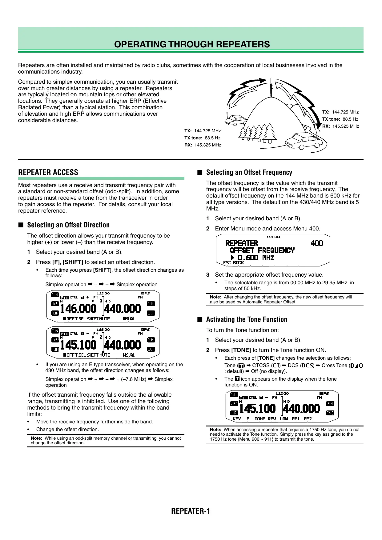
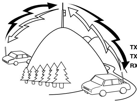
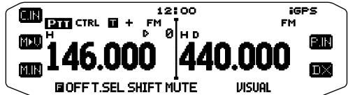
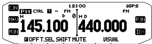
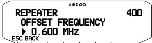
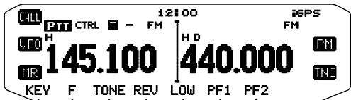
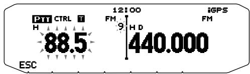
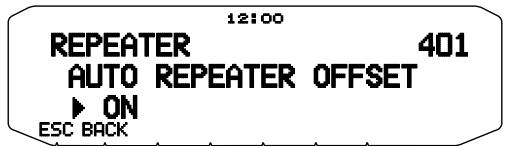
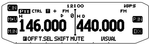
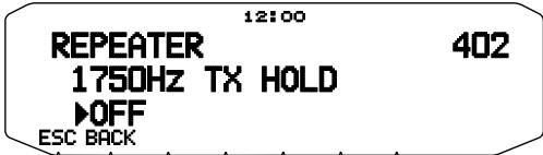
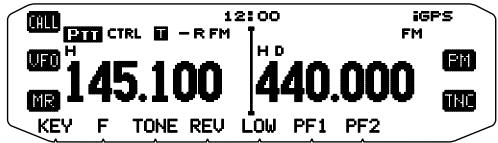
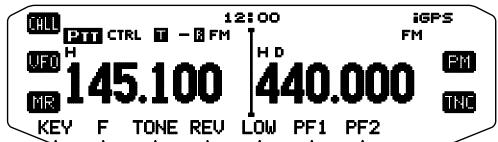
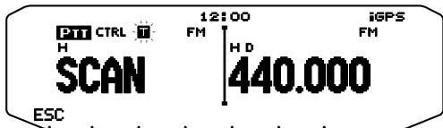
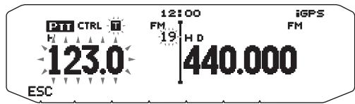

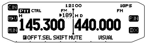

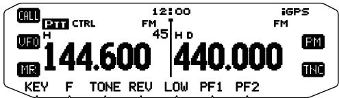

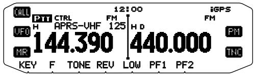

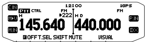
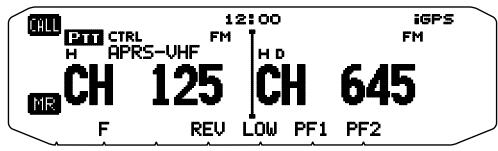

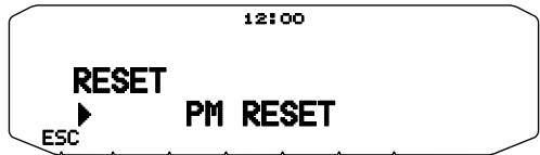


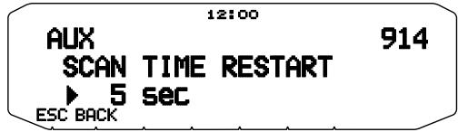
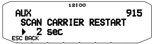
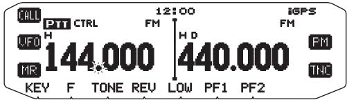
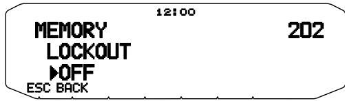
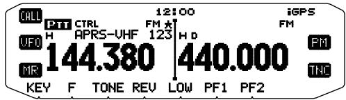
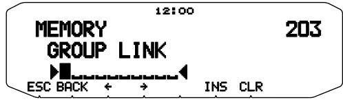
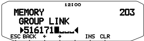
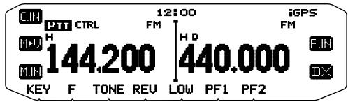
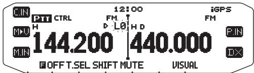
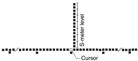

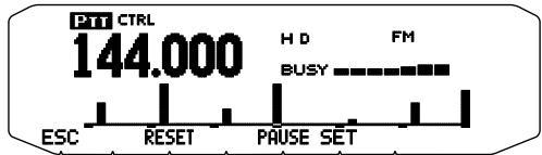
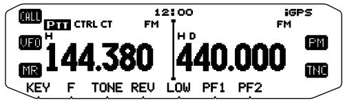
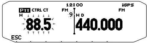
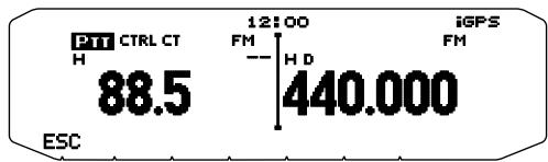

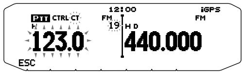
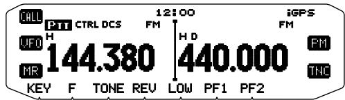
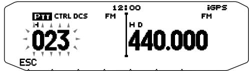
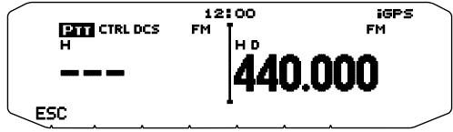

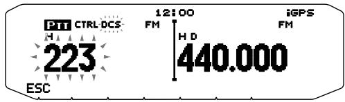


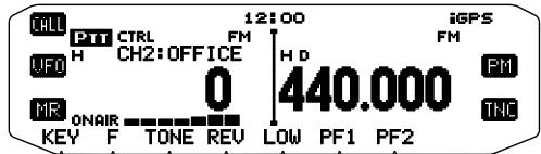
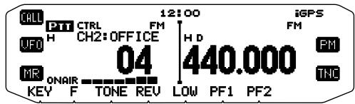
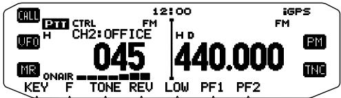
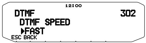
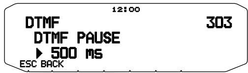
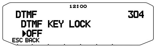


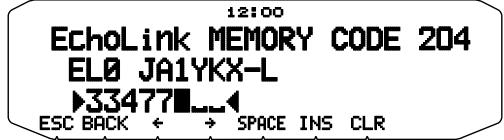
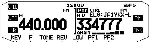

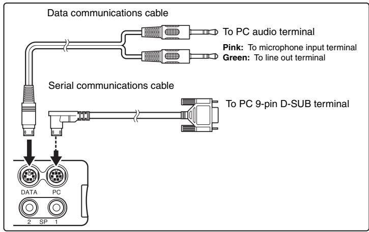
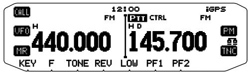
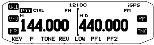
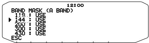
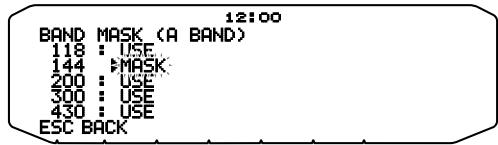
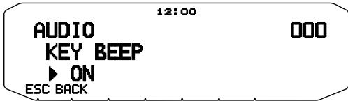

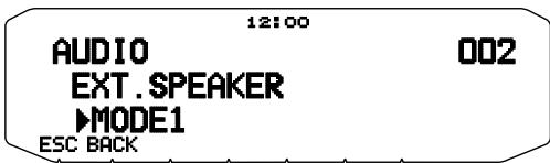
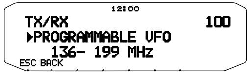
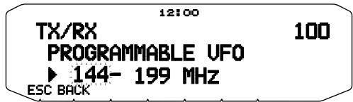
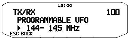
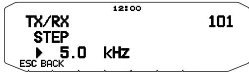
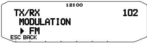
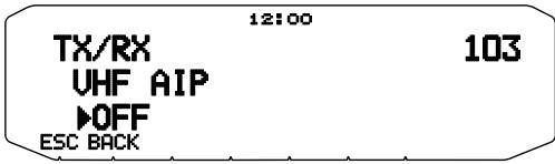
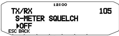
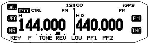
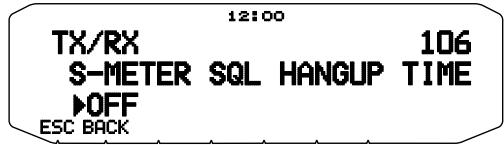
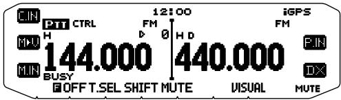
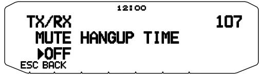
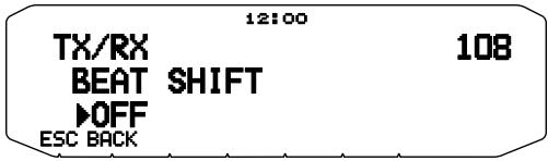
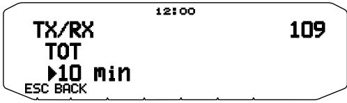
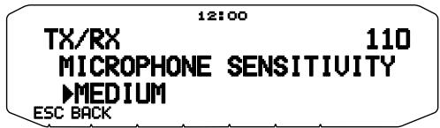


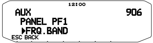
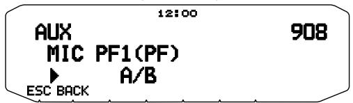
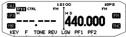
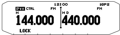
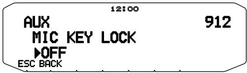
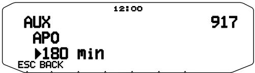
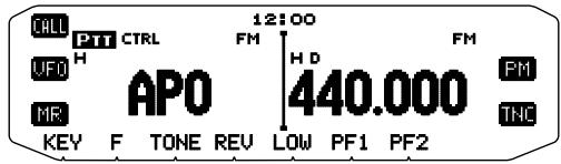
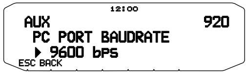

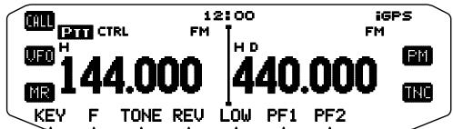
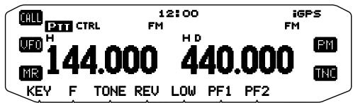

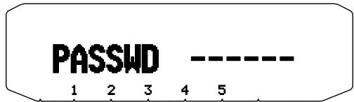
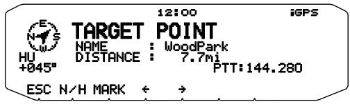
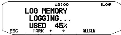
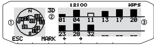
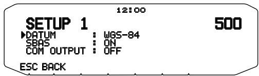
![12:00 SETUP 2 ►SENTENCE :[**GPGGA] [**GPRMC] ►GPGLLGPVT6 **GPGSA $GPZDA **GPGSU ESC BACK SELECT 501](/content/2025/01/83316/images/46479cc03aa6561e47392b16480e9fc8867c7fb249affb4749699a16907ab8c0.jpg)