
CR1071 - Industrial electronic module IFM - Free user manual and instructions
Find the device manual for free CR1071 IFM in PDF.


| Type | Process and dialogue module (PDM360 smart) for mobile machines |
| Display | Monochrome COG, transflective, 128 x 64 pixels, 59 x 30.5 mm (2.5") |
| Backlight | LED, adjustable brightness (0-100%) |
| Keys | 12 short-stroke backlit function keys, freely programmable |
| Contrast | Adjustable in 26 steps via configuration menu |
| Processor | Infineon C167CR, 20 MHz |
| Memory | 576 KB Flash (program/data), 48 KB SRAM, 1536 bytes FRAM (remanent), 128 bytes FRAM (retain) |
| Power Supply | 10...32 V DC, max. 240 mA at 24 V DC |
| Protection | IP 67 |
| Operating Temperature | -20...+70 °C |
| Storage Temperature | -30...+80 °C |
| Weight | 1.24 kg |
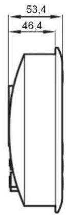
| Dimensions (W x H x D) | 109 x 165 x 53.4 mm |
| Cutout for Panel Mounting | 103 ± 0.5 x 154 ± 0.5 mm |
| Housing Material | Die-cast zinc, powder coated (RAL 9006) |
| Protective Film | Polyester with embossed keys |
| Interfaces | CAN (ISO 11898, CANopen), RS-232 |
| Inputs (CR1071) | 4 configurable: digital (NAMUR), frequency (max. 30 kHz) |
| Outputs (CR1071) | 4 configurable: high-side or PWM (max. 1 A per output, total 3 A) |
| Programming | CODESYS V2.3 (IEC 61131-3) with target visualisation |
| Mounting Options | Panel (clips), control cabinet (brackets), surface (RAM mount) |
| Approvals | CE, E1 (UN/ECE-R10), EN 61000-6-2/4, EN 61010-1, ISO 7637-2, EN 60068 |
Frequently Asked Questions - CR1071 IFM
User questions about CR1071 IFM
0 question about this device. Answer the ones you know or ask your own.
Ask a new question about this device
Download the instructions for your Industrial electronic module in PDF format for free! Find your manual CR1071 - IFM and take your electronic device back in hand. On this page are published all the documents necessary for the use of your device. CR1071 by IFM.
USER MANUAL CR1071 IFM
natural_image
Technical diagram showing a hand pressing a button into a mechanical component (no text or symbols present)
natural_image
Technical diagram of a mechanical joint or bracket with cross-hatching and a downward arrow indicating force or direction (no text or symbols present)
natural_image
Technical line drawing of a mechanical joint or bracket (no text or symbols)natural_image
Technical diagram showing a screwdriver inserted into a mechanical component with directional arrows indicating movement (no text or symbols present)Entnahmeschritte:

This description is part of the unit. It contains texts and drawings concerning the correct handling of the module and must be read before installation or use.
Observe the information of the description. Non-observance of the notes, operation which is not in accordance with use as prescribed below, wrong installation or handling can result in serious harm concerning the safety of persons and plant.
The instructions are for authorised persons according to the EMC and low voltage guidelines. The process and dialogue modules must be installed and commissioned by a skilled electrician (programmer or service technician).
If the unit is not supplied by the mobile on-board system (12/24 V battery operation) it must be ensured that the external voltage is generated and supplied according to the criteria for safety extra-low voltage (SELV) as this is supplied without further measures to the connected controller, the sensors, and the actuators.
The wiring of all signals in connection with the SELV circuit of the unit must also comply with the SELV criteria (safe extra-low voltage, safe electrical separation from other electric circuits).
If the supplied SELV voltage has an external connection to ground (SELV becomes PELV) the responsibility lies with the user and the respective national regulations for installation must be complied with. All statements in these operating instructions refer to the unit the SELV voltage of which is not grounded.
The connectors may only be supplied with the signals indicated in the technical data or on the unit label and only the approved accessories of ifm electronic gmbh may be connected.
The unit can be operated within a wide temperature range according to the technical specification indicated below. Due to the additional self-heating the housing walls can have high perceptible temperatures when touched in hot environments.
In case of malfunctions or uncertainties please contact the manufacturer. Tampering with the unit can lead to considerable risks for the safety of persons and plant. It is not permitted and leads to the exclusion of any liability and warranty claims.
Electromagnetic compatibility
This is a class A installation. It can cause radio interference in domestic areas. In this case the operator is requested to take appropriate measures.
Contents
- Function and features ...... page 20
Features at a glance . . . . . . . . . . . . . . . . . . . . . . . . . . . . . . . . . . . . . . . . . . . . page 20
Accessories. . . . . . . . . . . . . . . . . . . . . . . . . . . . . . . . . . . . . . . . . . . . . . . page 20
- Programming ...... page 21
Configuration and online help. . . . . . . . . . . . . . . . . . . . . . . . . page 21
- Mounting
Mounting accessories . . . . . . . . . . . . . . . . . . . . . . . . . . . . . . . . . . . . . . page 22
Seal/vibration absorber . . . . . . . . . . . . . . . . . . . . . . . . . . . . . . page 22
Control cabinet mounting with mounting brackets (fixing set). page 23
Panel mounting with clips (snap-in set) . . . . . . . . . . . . . . . page 24
Surface mounting with RAM ^ mount system . . . . . . . . . . . page 25
-
Electrical connection .... page 26
-
Maintenance, repair and disposal . . . . . . . . . . . . . . . . . . . . . . . page 27
-
Approvals/standards . . . . . . . . . . . . . . . . . . . . . . . . . . . . . . . . . . . . . . . . . page 27
Annex
Technical data CR1070
Dimension . . . . . . . . . . . . . . . . . . . . . . . . . . . . . . . . . . . . . . . . . . . . . . . . page 28
Display.... page 28
Mechanical data . . . . . . . . . . . . . . . . . . . . . . . . . . . . . . . . . . . . . . . . . . . . . . page 28
Electrical data.... page 28
Interfaces . . . . . . . . . . . . . . . . . . . . . . . . . . . . . . . . . . . . . . . . . . . . . . . . . . . . . . . page 29
Software / Programming . . . . . . . . . . . . . . . . . . . . . . . . . . . . . . . . . . page 29
Other features . . . . . . . . . . . . . . . . . . . . . . . . . . . . . . . . . . . . . . . . . page 29
Tests / Approvals. . . . . . . . . . . . . . . . . . . . . . . . . . . . . . . . . . . . . . . . . . . . page 29
Wiring . . . . . . . . . . . . . . . . . . . . . . . . . . . . . . . . . . . . . . . . . . . . . . . . page 29
Technical data CR1071
Dimension . . . . . . . . . . . . . . . . . . . . . . . . . . . . . . . . . . . . . . . . . . . . . . . . . page 30
Display.... page 30
Mechanical data . . . . . . . . . . . . . . . . . . . . . . . . . . . . . . . . . . . . . . . . . . . . page 30
Electrical data.... page 30
Interfaces . . . . . . . . . . . . . . . . . . . . . . . . . . . . . . . . . . . . . . . . . . . . . . . . page 31
Software / Programming . . . . . . . . . . . . . . . . . . . . . . . . . . . . page 31
Other features . . . . . . . . . . . . . . . . . . . . . . . . . . . . . . . . . . . . . . . . . . page 31
Tests / Approvals. . . . . . . . . . . . . . . . . . . . . . . . . . . . . . . . . . . . . . . . . . . . . page 31
Wiring . . . . . . . . . . . . . . . . . . . . . . . . . . . . . . . . . . . . . . . . . . . . . . . . . . . . . page 31
Characteristics of the inputs / outputs . . . . . . . . . . . . . . . . page 32
This device manual applies to devices as from the production status CR107...AJ
1. Function and features
The process and dialogue module PDM360 smart smart is a programmable graphic display for controlling, parameter-setting and operation of mobile machines and plants.
Communication with other system components, e.g. decentralised I/O modules, is handled via a CAN interface using the CANopen protocol.
The RS-232 interface and the inputs/outputs (only CR1071) form a universal platform for networking and communication with other units.

The process and dialogue module PDM360 smart is not approved for safety-related tasks in the sense of the safety of persons.
Features at a glance
- Display 128 x 64 pixels with 12 backlit function keys
- Closed metal housing (IP 67) suitable for panel mounting and surface mounting outside or in the cabin
• Freely programmable in accordance with IEC 61131-3 with target visualisation
• CAN interface with CANopen protocol - RS-232 interface
2. Programming
The application software can be easily created by the user with the ifm programming system CODESYS (version 2.3.5 or higher) according to IEC 61131-3.
As download file (HTML file) the ifm online help CODESYS V2.3 is available on the internet:
www.ifm.com
→ Data sheet direct → CR107... → Download/Software 1)
The user is responsible for the safe functioning of the application programs which he creates himself. If necessary, he must additionally obtain an approval according to the corresponding national regulations by the corresponding testing and supervisory organisations.
Configuration and online help
Pressing the F1 and F5 keys simultaneously at power on opens the configuration menu:
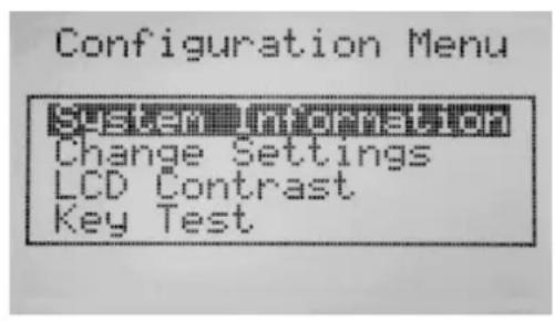
- System Information
- Download identifier for CODESYS
- Transmission rate CAN interface
- Transmission rate RS-232 interface
- Contrast setting of the display
- Version number of the loaded runtime system (if no runtime system is loaded, "no" is indicated)
-
Application loaded (yes/no)
-
Change Settings
- Download ID, CAN baud rate, etc.
• LCD Contrast (0...25)
• Key Test (function check of the keys)
You can find more information about programming and use in the PDM online help on the CD-ROM "ecomatmobile software, tools and documentation" (art. no. CP9008).
The PDM online help contains descriptions for the following topics:
- PDM 360 smart device configuration
- Communication and programming interfaces
- Loading of the operating system
- System messages
- General system flags
• Diagnostic information and error flags - First steps for creating a new project
- Integration of bitmaps into visualisation pages
• Description of the PDM specific libraries
3. Mounting
■Mounting accessories
The unit is supplied without mounting accessories.
Depending on the intended location and type of mounting the following mounting accessories are available:
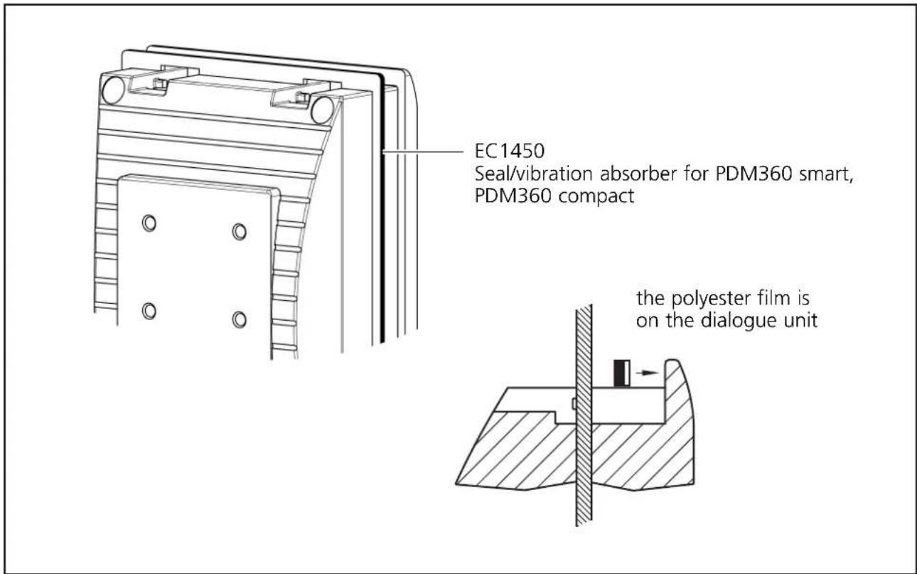
• EC1450, seal/vibration absorber for panel/control cabinet mounting
• EC1452, snap-in set for panel mounting*
• EC1453, fixing set for control cabinet mounting*
- EC1410...EC1414, RAM ^ mount system for surface mounting
You can find more information about the available accessories at:
www.ifm.com → Data sheet direct → e.g. CR1070 → Accessories
*) Use the snap-in set (EC1452) and the fixing set (EC1453) only in conjunction with the seal/vibration absorber (EC1450).
■Seal/vibration absorber
Slide the seal/vibration absorber over the unit from the back.
■Control cabinet mounting with mounting brackets (fixing set EC1453)
The mounting brackets enable the horizontal, vertical or upside-down mounting of the dialogue module. This type of mounting is suited for materials with a thickness of max. 8 mm.
Please take into account the required clearance space for the mounting brackets!
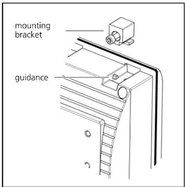

Mounting steps:
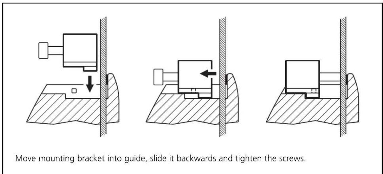
■Panel mounting with clips (snap-in set EC1452)
Preferably select this type of mounting when the unit is to be laid in the horizontal position as it is only held by the force of the clips.
The angle of inclination of the panel must not exceed 45^ .

Note when selecting the mounting location:
To loosen the clips the back of the unit must be accessible.
This type of mounting is suited for materials with a thickness of max. 5 mm.
Mounting steps:

natural_image
Technical diagram showing a hand operating a valve with an arrow indicating motion (no text or symbols present)
natural_image
Cross-sectional diagram of a mechanical joint or bracket with hatched shading and a downward arrow indicating force or direction (no text or symbols present)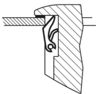
natural_image
Technical drawing of a mechanical joint or bracket with hatched fill (no text or symbols)Insert clips Press the unit into the cutout end position
Removing the unit from the panel
To insert the screwdriver between the cut-out of the panel and the clip, the grooved chamfer of the clips must be fitted with a slot.
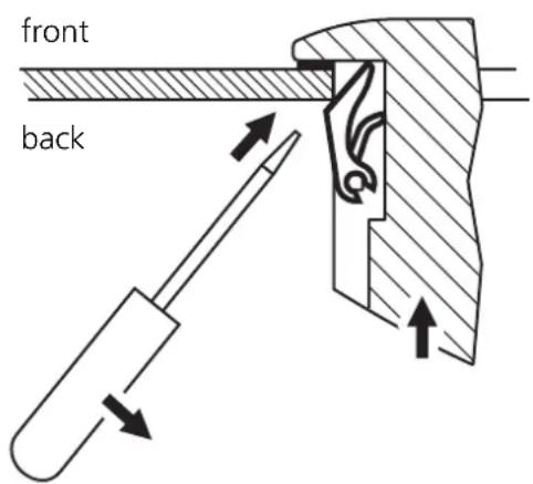
Steps for removal:
- Insert the screwdriver into the slot of the clips on the back.
- Angle the screwdriver and compress the springs of the clips.
- Remove the unit from the cutout.
■Surface mounting with RAM ^ mount system (EC1410...EC1414)
Using the RAM ^® mount components, available as accessories, the dialogue unit can be used as a firmly mounted desktop unit. Two balls allow variable orientation of the unit.
The back of the unit has been prepared for fixing the mounting plate. 4 x M5 (useable thread depth: 8 mm)

You can find more information about the available RAM ^® mount components at: www.ifm.com → Data sheet direct → e.g. CR1070 → Accessories
4. Electrical connection
To guarantee the electrical interference protection of the module, the housing must be connected to GND (e.g. to the ground of the vehicle).
To protect the whole system (dialogue unit and wiring) the supply cables must be protected using a 7.5 A fuse.
Connector 1, pin 2 and socket 3, pin 5 (only CR1071)
The supply cables, interfaces and inputs/outputs (CR1071) are connected via M12 connectors on the back of the unit.
Connector 1 (male): supply, CAN interface
Connector 2 (female): RS232 interface, CAN interface
Connector 3 (female): inputs
Connector 4 (female): outputs
CR1070CR1071

natural_image
Technical line drawing of a rectangular device with two labeled ports (1 and 2), no text or symbols present.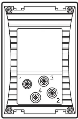
For the pin connection of the connector see the "technical data", CR1070 (page 29) and CR1071 (page 31).
Screen signal cables in EMC-critical applications or provide all connection cables with ferrite sleeves.
Recommendation: impedance 321 Ohm (100 MHz)
The ferrite sleeves ensure CE conformity and suppress conducted interference.
To prevent corrosion between the connectors and the diecast zinc housing of the unit, do not use any sockets with stainless steel fitting.
Do not connect or disconnect the serial interface while live. Connecting or disconnecting the serial interface while live can lead to undefined states, causing damage to the RS-232 driver module.
5. Maintenance, repair and disposal
The process and dialogue module is maintenance-free and may only be repaired by the manufacturer. The unit must be disposed of in accordance with the national environmental regulations.
6. Approvals/standards
The EC declaration of conformity and approvals can be found at:
www.ifm.com → Data sheet search → e.g. CR1070 → More information
CR1070
Process and dialogue module
PDM 360 smart
128 x 64 pixels
monochrome display
12 freely programmable backlit function keys
10...32 V DC
CE


Technical data Intelligent compact di
| for use in mobile machines | |
| Display | |
| Display COG, monochrome, transflective | with graphics capabilities, 128 x 64 pixels, 59 x 30.5 mm (2.5") |
| Background illumination LED | |
| Contrast adjustable in 26 steps via the configuration menu | |
| Sets of characters can be uploaded individually | |
| Mechanical data | |
| Mounting variants • panel mounting | support from the front via lip around the cover, fixing with clips when mounted into a panel or mounting brackets when mounted into a control cabinet• surface mounting via RAM® mount system (mounting accessories not included) |
| Dimensions (W x H x D) 109 x 165 x 53.4 mm | |
| Cutout for panel mounting (W x H) | 103 ± 0.5 x 154 ± 0.5 mm |
| Housing material | die-cast zinc, powder coated (RAL 9006) |
| Protective film | polyester with embossed keys |
| Keys | 12 short-stroke keys, with tactile feedback backlit (brightness 0...100% adjustable) freely programmable (softkey function) |
| Encoder | - |
| Protection | IP 67 |
| Operating temperature | -20...+70°C |
| Storage temperature | -30...+80°C |
| Weight | 1.20 kg |
| Electrical data | |
| Operating voltage | 10...32 V DC |
| Current consumption | 240 mA (at 24 V DC) |
| Short-circuit / reverse polarity protection | external fuse |
| Processor | Infineon C167CR, 20 Mhz |
| Program and data memory | 576 Kbytes (Flash) |
| Data memory | 48 Kbytes (SRAM) |
| Data memory (remanent) | 1536 bytes (FRAM) |
| Data memory (retain) | 128 bytes (FRAM) |
ifm electronic gmbh • Friedrichstraße 1 • 45128 Essen
We reserve the right to make technical alterations without prior notice. CR1070 / page 1
17.09.2014
| CR1070 Technical data | ||
| Interfaces | ||
| CAN 1 interface in accordance with ISO | 11898 version 2.0 Bprotocol CANopen (CiA DS 301 V4), profile DS 401baud rate: 50...500 Kbits/s (default 125 Kbits/s)connection via 5-pole M12 connector | |
| RS 232 transmission rate up to 57,6 Kbaud | connection via 5-pole M12 connectorsignals: RxD, TxD, GND | |
| Software/Programming | ||
| Programming system CODESYS version | 2.3 (IEC 61131-3) | |
| Graphic functions via integrated target visualisation | ||
| Other features | ||
| Temperature monitoring sensor for measuring the temperature inside the housing | ||
| Tests/Approvals | ||
| CE marking | EN 61000-6-2 (Electromagnetic compatibility (EMC), Immunity)EN 61000-6-4 (Electromagnetic compatibility (EMC), Emission standard)EN 61010-1 (Safety requirements for electrical equipment for measurement, control and laboratory use) | |
| E1 marking UN/ECE-R10 (noise emission and noise immunity) | ||
| Noise immunity ISO 7637-2 | ||
| Other tests | EN 60068 for climatic and mechanical testing | |
| Back of the unit | ||
| Wiring | 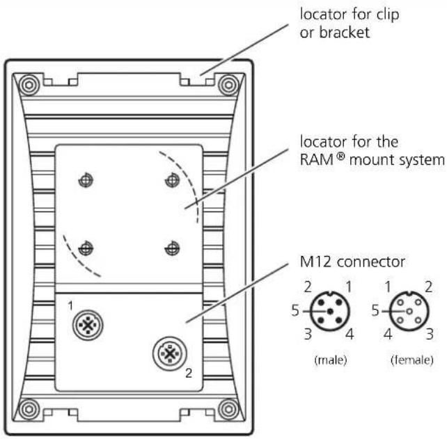 | |
| *) electrically connected | Connector 1Supply, CAN*Pin Potential1 Shield2 10...32 V DC3 GND4 CAN_H5 CAN_L | Connector 2RS232, CAN*Pin Potential1 RS232_TxD2 RS232_RxD3 GND4 CAN_H5 CAN_L |
ifm electronic gmbh • Friedrichstraße 1 • 45128 Essen
We reserve the right to make technical alterations without prior notice.
CR1070 / page 2 17.09.2014
CR1071
Process and dialogue module
PDM 360 smart
128 x 64 pixels
monochrome display
12 freely programmable backlit function keys
4 inputs / 4 outputs
10...32 V DC
CE


Technical data Intelligent compact d
Display
| Display COG, monochrome, transflective |
| Background illumination LED |
| Contrast adjustable in 26 steps via the c |
| Sets of characters can be uploaded indiv |
Mechanical data
| Mounting variants • panel mounting |
| Dimensions (W x H x D) 109 x 165 x 53. |
| Cutout for panel mounting (W x H) |
| Housing material |
| Protective film |
| Keys |
| Encoder |
| Protection |
| Operating temperature |
| Storage temperature |
| Weight |
| Electrical data |
| Operating voltage |
| Current consumption |
| Short-circuit / reverse polarity protection |
| Processor |
| Program and data memory |
| Data memory |
| Data memory (remanent) |
| Data memory (retain) |
play
for use in mobile machines
, with graphics capabilities,
128 x 64 pixels, 59 x 30.5 mm (2.5")
configuration menu
idually
support from the front via lip around the cover,
fixing with clips when mounted into a panel
or mounting brackets when mounted into a control cabinet
- surface mounting
via RAM ^® mount system
(mounting accessories not included)
mm
103 ± 0.5 × 154 ± 0.5 mm
die-cast zinc, powder coated (RAL 9006)
polyester with embossed keys
12 short-stroke keys, with tactile feedback
backlit (brightness 0...100% adjustable)
freely programmable (softkey function)
-
IP 67
-20...+70°C
-30...+80°C
1.24 kg
We reserve the right to make technical alterations without prior notice. CR1071 / page 1
17.09.2014
| CR1071 Technical data | ||||
| Interfaces | ||||
| CAN 1 interface in accordance with ISO | 11898 version 2.0 Bprotocol CANopen (CiA DS 301 V4), profile DS 401baud rate: 50...500 Kbits/s (default 125 Kbits/s)connection via 5-pole M12 connector | |||
| RS 232 transmission rate up to 57,6 Kbaud | connection via 5-pole M12 connectorsignals: RxD, TxD, GND | |||
| Software/Programming | ||||
| Programming system CODESYS version | 2.3 (IEC 61131-3) | |||
| Graphic functions via integrated target visualisation | ||||
| Other features | ||||
| Temperature monitoring sensor for measuring the temperature inside the housing | ||||
| Tests/Approvals | ||||
| CE marking | EN 61000-6-2 (Electromagnetic compatibility (EMC), Immunity)EN 61000-6-4 (Electromagnetic compatibility (EMC), Emission standard)EN 61010-1 (Safety requirements for electrical equipment for measurement, control and laboratory use) | |||
| E1 marking UN/ECE-R10 (noise emission and noise immunity) | ||||
| Noise immunity ISO 7637-2 | ||||
| Other tests | EN 60068 for climatic and mechanical testing | |||
| Back of the unit | ||||
| Wiring |  | |||
| (*) electrically connected | Connector 1Supply, CAN*Pin Potential1 Shield2 10...32 V DC3 GND4 CAN_H5 CAN_L | Connector 2RS232, CAN*Pin Potential1 RS232_TxD2 RS232_RxD3 GND4 CAN_H5 CAN_L | Connector 3InputsPin Potential1 IN 12 IN 23 IN 34 IN 45 +VBB(out) | Connector 4OutputsPin Potential1 OUT 12 OUT 23 OUT 34 OUT 45 GND |
| Connector 1Supply, CAN* | |
| Pin | Potential |
| 1 | Shield |
| 2 | 10...32 V DC |
| 3 | GND |
| 4 | CAN_H |
| 5 | CAN_L |
| Connector 2RS232, CAN* | |
| Pin | Potential |
| 1 | RS232_TxD |
| 2 | RS232_RxD |
| 3 | GND |
| 4 | CAN_H |
| 5 | CAN_L |
| Connector 3Inputs | |
| Pin | Potential |
| 1 | IN 1 |
| 2 | IN 2 |
| 3 | IN 3 |
| 4 | IN 4 |
| 5 | +VBB(out) |
| Connector 4Outputs | |
| Pin | Potential |
| 1 | OUT 1 |
| 2 | OUT 2 |
| 3 | OUT 3 |
| 4 | OUT 4 |
| 5 | GND |
We reserve the right to make technical alterations without prior notice.
CR1071 / page 2 17.09.2014
| CR1071 Characteristics of the inputs | outputs |
| Inputs | |
| %IX0.00...03 ( B_L , I_L )can be configured as ... switch-on level | ■ Digital inputs for positive sensor signals, with diagnostic capability *)0.7 U Bswitch-off level 0.4 U Binput resistance 3.2 kΩinput frequency max. 50 Hz |
| ■Frequency inputs for positive sensor signalswith diagnostic capability, evaluation with integrated comparatorswitch-on level 0.43...0.73 U Bswitch-off level 0.29 U Binput resistance 3.2 kΩinput frequency max. 30 kHz | |
| *) NAMUR inputs Digital inputs with diagnostic capability can be used as NAMUR inputs when usedwith an external resistor connection.supply voltage 5...25 V; e.g. ifm NAMUR sensors NT5001...NN5002 | |
| Outputs | |
| %QX0.00...03 ( B_H , PWM) ■Semiconductor outputscan be configured as ... | positive switching (high side), short-circuit and overload protectedswitching voltage 10...32 V DCSwitching current max. 1 Atotal current max. 3 Aoutput frequency max. 100 Hz (depending on the load) |
| ■PWM outputsPWM frequency max. 250 Hzpulse ratio 1...99 %resolution depends on the PWM frequencyload current max. 1 Atotal current max. 3 A | |
| AbbreviationsA = analogue B_H = binary High Side B_L = binary Low SideFRQ/CYL = frequency inputs I_H = pulse High Side I_L = pulse Low SidePWM = pulse width modulation PWM_I = current-controlled output%IW... = IEC address for analogue input%IX... = IEC address for binary input%QX... = IEC address for binary output | |
ifm electronic gmbh • Friedrichstraße 1 • 45128 Essen
We reserve the right to make technical alterations without prior notice.
CR1071 / page 3 17.09.2014




- Entnahmeschritte:
- Electromagnetic compatibility
- Contents
- Annex
- Function and features
- Features at a glance
- Programming
- Configuration and online help
- Mounting
- ■Mounting accessories
- ■Seal/vibration absorber
- ■Control cabinet mounting with mounting brackets (fixing set EC1453)
- ■Panel mounting with clips (snap-in set EC1452)
- Removing the unit from the panel
- ■Surface mounting with RAM ^ mount system (EC1410...EC1414)
- Electrical connection
- Maintenance, repair and disposal
- Approvals/standards
- CR1070
- CR1071
Brand : IFM
Model : CR1071
Category : Industrial electronic module