
CEP-12 - Angle Grinder Truper - Free user manual and instructions
Find the device manual for free CEP-12 Truper in PDF.


| Product Type | Portable Planer |
| Brand | Truper |
| Model | CEP-12 |
| Code | 16240 |
| Dimensions (L x W x H) | 22.8" x 27" x 18.2" |
| Weight | 68 lbs |
| Voltage | 127 V~ |
| Frequency | 60 Hz |
| Current | 15 A |
| Power | 2 1/4 Hp |
| Feed Speed | 26.2 ft/min |
| Maximum Cutting Depth | 1/8" |
| Minimum Workpiece Length | 5" |
| Maximum Workpiece Width | 12-1/2" |
| Workpiece Thickness Range | 0.2" - 6" |
| Work Cycle | 120 min work / 30 min rest, max 6 hrs daily |
| Insulation Class | Class I |
| Thermal Insulation Motor Winding | Class B |
| Power Cord Grip Type | Type "Y" |
| Recommended Extension Cord (0-49 ft) | 14 AWG, 3-conductor grounded |
| Cutter Head Adjustment | 0.05" per gear tooth step |
| Blade Replacement | Both blades simultaneously, height set to 1/16" using gauge |
| Safety Features | Switch with removable safety key, overload protection |
| Included Accessories | Anti-chip guard, table extensions, blade height gauge |
| Warranty | 1 year |
Frequently Asked Questions - CEP-12 Truper
User questions about CEP-12 Truper
0 question about this device. Answer the ones you know or ask your own.
Ask a new question about this device
Download the instructions for your Angle Grinder in PDF format for free! Find your manual CEP-12 - Truper and take your electronic device back in hand. On this page are published all the documents necessary for the use of your device. CEP-12 by Truper.
USER MANUAL CEP-12 Truper
natural_image
3D technical illustration of a TRUPER industrial machine with open base and control panel (no text or symbols on the device itself)natural_image
3D technical illustration of a mechanical device with no visible text or symbols


natural_image
3D technical illustration of a mechanical assembly with wooden components and a dashed arc indicating motion (no text or symbols)Puesta en marcha

TRUPER®
Mantenimiento
natural_image
3D technical illustration of a TRUPER industrial machine with mounting base and control panel (no text or symbols on the device itself)Applies for:
Model Code
CEP-12
16240
Technical data 3
Power Requirements 3

General Power Tool Safety Warnings 4

Safety Warnings for Power Planers 5
Parts 6
Assembly 7
Adjustments 8
Start Up 9
Maintenance....11
Troubleshooting 12
Notes 13
Authorized Service Centers 15
Warranty Policy 16

CAUTION
To gain the best performance of the tool, prolong the duty life, make the Warranty valid if necessary, and to avoid hazards of fatal injuries please read and understand this Manual before using the tool.
Keep this manual for future references.
The illustrations in this manual are for reference only. They might be different from the real tool.

CEP-12
| Code | 16240 |
| Description | Portable Planer |
| Measurements Weight | 22,8" x 27" x 18,2" 68 lbs |
| Voltage | 127 V~ |
| Frequency | 60 Hz |
| Current | 15 A |
| Power | 2 1/4 Hp |
| Speed Cutting Speed | |
| Work Cycle | 120 minutes' work and 30 minutes' rest. Maximum 6 hours daily. |
| Conductors | 14 AWG x 3C with 221 °F insulation. |
| Insulation | Class I |
Power Cord Grips used in this product: Type "Y".
Tool Build Quality: Basic insulation
Thermal insulation on motor winding: Class B
WARNING Avoid the risk of electric shock or severe injury. When the power cable gets damaged
it should only be replaced by the manufacturer or at a TRUPER Authorized Service Center.
The build quality of the electric insulation is altered if spills or liquid gets into the tool while in use.
Do not expose to rain, liquids and/or dampness.
WARNING Before gaining access to the terminals all power sources should be disconnected.

Power Requirements
WARNING The tool shall be grounded while in use to prevent an electric shock. • Connect the plug into a properly grounded outlet as shown in example A. Not all the outlets are properly grounded. If in doubt verify with a certified electrician. • If the outlet you plan to be using for the tool has two poles (2 orifices). FOR NO REASON AT ALL DO NOT REMOVE OR ALTER THE GROUND CONDUCTOR IN THE PLUG. Use a temporary adaptor as shown in example B and always connect the ground lug as indicated.

CAUTION When using an extension cable, verify the gauge is enough
for the power that the tool needs. A lower gauge cable will cause voltage drop in the line, resulting in power loss and the motor will overheat. The following table shows the right size to use depending on cable's length and the ampere capability shown in the tool's nameplate. When in doubt use the next higher gauge.

Ampere Capacity
| From 0 and up to 10 A |
| From 10 and up to 13 A |
| From 13 and up to 15 A |
| From 15 and up to 20 A |
Number of Conductors
| 3 (one grounded) |
Extension Gauge
| From 5,9 ft to 49 ft | | Higher than 49 ft |
| 18 AWG | 16 AWG |
| 16 AWG | 14 AWG |
| 14 AWG | 12 AWG |
| 8 AWG | 6 AWG |
* It is safe to use only if the extensions themselves have an artifact for over current protection. AWG = American Wire Gauge. Reference: NMX-J-195-ANCE
WARNING When operating power tools outdoors use a grounded extension cable labeled "Outdoor Use" volteck. brand. These extension cables are specially designed to be used outdoors and reduce the risk of an electric shock.
WARNING! Read carefully all safety warnings and instructions listed below. Failure to comply with any of these warnings may result in electric shock, fire and / or severe damage. Save all warnings and instructions for future references.
Work area
Keep your work area clean, and well lit.
Cluttered and dark areas may cause accidents.

Never use the tool in explosive atmospheres, such as in the presence of flammable liquids, gases or dust.
Sparks generated by power tools may ignite the flammable material.

Keep children and bystanders at a safe distance while operating the tool.
Distractions may cause loosing control.

Electrical Safety
The tool plug must match the power outlet. Never modify the plug in any way. Do not use any adapter plugs with grounded power tools.
Modified plugs and different power outlets increase the risk of electric shock.

Avoid body contact with grounded surfaces, such as pipes, radiators, electric ranges and refrigerators.
The risk of electric shock increases if your body is grounded.
Do not expose the tool to rain or wet conditions.
Water entering into the tool increases the risk of electric shock.
Do not force the cord. Never use the cord to carry, lift or unplug the tool. Keep the cord away from heat, oil, sharp edges or moving parts.
Damaged or entangled cords increase the risk of electric shock.
When operating a tool outdoors, use an extension cord suitable for outdoor use.
Using an adequate outdoor extension cord reduces the risk of electric shock.
If operating the tool in a damp location cannot be avoided, use a ground fault circuit interrupter (GFCI) protected supply.
Using a GFCI reduces the risk of electric shock.
Personal safety
Stay alert, watch what you are doing and use common sense when operating a tool. Do not use a power tool while you are tired or under the influence of drugs, alcohol or medication.
A moment of distraction while operating the tool may result in personal injury.
Use personal protective equipment. Always wear eye protection.
Protective equipment such as safety glasses, anti-dust mask, non-skid shoes, hard hats and hearing protection used in the right conditions significantly reduce personal injury.


Prevent unintentional starting up. Ensure the switch is in the "OFF" position before connecting into the power source and / or battery as well as when carrying the tool.
Transporting power tools with the finger on the switch or connecting power tools with the switch in the "ON" position may cause accidents.
Remove any wrench or vice before turning the power tool on.
Wrenches or vices left attached to rotating parts of the tool may result in personal injury.
Do not overreach. Keep proper footing and balance at all times.
This enables a better control on the tool during unexpected situations.
Dress properly. Do not wear loose clothing or jewelry. Keep hair, clothes and gloves away from the moving parts.
Loose clothes or long hair may get caught in moving parts.

If you have dust extraction and recollection devices connected onto the tool, inspect their connections and use them correctly.
Using these devices reduce dust-related risks.
Power Tools Use and Care
Do not force the tool. Use the adequate tool for your application.

The correct tool delivers a better and safer job at the rate for which it was designed.
Do not use the tool if the switch is not working properly.
Any power tool that cannot be turned ON or OFF is dangerous and should be repaired before operating.
Disconnect the tool from the power source and / or battery before making any adjustments, changing accessories or storing.
These measures reduce the risk of accidentally starting the tool.
Store tools out of the reach of children. Do not allow persons that are not familiar with the tool or its instructions to operate the tool.

Power tools are dangerous in the hands of untrained users.
Service the tool. Check the mobile parts are not misaligned or stuck. There should not be broken parts or other conditions that may affect its operation. Repair any damage before using the tool.
Most accidents are caused due to poor maintenance to the tools.

Keep the cutting accessories sharp and clean.
Cutting accessories in good working conditions are less likely to bind and are easier to control.
Use the tool, components and accessories in accordance with these instructions and the projected way to use it for the type of tool when in adequate working conditions.
Using the tool for applications different from those it was designed for, could result in a hazardous situation.
Service
Repair the tool in a TRUPER Authorized Service Center using only identical spare parts.
This will ensure that the safety of the power tool is maintained.
Children or people with reduced physical, sensory or mental capabilities shall not operate the tool, neither inexperienced people or without knowledge in the use of the tool, unless supervised by a person responsible of their safety or if receiving previous instructions about the tool operation.
Children shall be kept under supervision to double-check they will not play with the tool. Tight supervision shall be used with children or disabled persons to prevent from using or being close to any household tool.

Before Operating the Tool
- The extension cable shall be entirely unrolled to prevent a potential overheating.
- Double check the voltage in the power outlet is equal to the rated power described in the equipment nameplate.
CAUTION • Remove from the workplace all types of rags, clothes, cables, ropes or any other object that could get trapped in the planer blades.
WARNING • Remove nails, screws or any other object from the work piece. These objects may damage the blades and the tool. Also, represent a safety hazard.
CAUTION • The blades are sharp and can easily cause wounds. Use care when handling the blades and when assembling the cutter head.
CAUTION • Before starting any job, make sure the installation screws in the blades are perfectly tight.
- Before operating the tool, turn it ON leave it running a couple of minutes. Look for vibrations indicating a faulty installation or an unbalanced blade.
- Double check the blades are correctly mounted as described in the instructions.
While Operating the Tool
CAUTION • Hold the work piece firmly with both hands and keep them away from the cutter head.
- Do not force the work piece into the machine. Allow the brush to gain the proper feed speed.
- Verify the feeding rollers occasionally to make sure wood chips and burrs are not housed into the components. If the bearings are not sitting firmly, the feeding rolls will not keep the work piece against the bed, causing it to travel back.
WARNING • Plan only wood pieces.
- Use solid wood, with no loose knots and as few firm knots as possible.
- Never stand directly in the entryway or exit of the piece. Stand always aside the machine.
CAUTION • Make sure the blades are not in contact with the workpiece when connecting the machine.
- Before cutting, wait for the blades to reach full speed.
CAUTION • Never leave the tool ON unsupervised.
• After long periods or running, the metallic parts can be very hot. - When possible, use a dust extraction system.
After Operating the Tool
- Before trying to carry out adjustments, turn OFF the tool and wait for the blades to come to a complete stop.
DANGER • Never try to retrieve stuck work pieces from the cutter head using your hands. To retrieve a stuck piece, turn OFF and disconnect the tool. Use a stick to remove the shavings. - When necessary, replace both blades at the same time. Otherwise, the resulting unbalance will cause vibrations and will shorten the useful life of the blades and the tool. Handle blades with extreme care.

Assembly
Fixing the Planer to a Surface
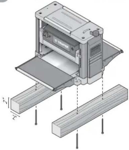
- The planer shall be fixed on a flat, leveled, stable surface that will support safely the planer weight along with the work pieces.
- The planer shall be secured to this surface using four M8 x 2" Allen screws
- If the planer is not mounted onto a base, mount it onto two pieces of wood to assure stability.

Orifice for the screws with bores in the base

TRUPER®
natural_image
Technical illustration of a machine with wooden base and two feet side supports, showing internal components (no text or symbols)Blades Replacement and Mounting
CAUTION • Wear safety gloves to handle the cutter head and the blades to prevent cuts and lacerations in your hands.
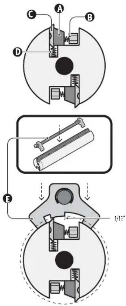
• To replace worn blades set the cutter head and turn it manually until gaining access to one of the blades. To carry out this operation the anti-woods guard shall not be mounted.
- Loosen the blocking bar (A) turning the fastening screws (B) in a clockwise direction. The blades (C) rest against the spring (D) and will be expelled when the blocking bar is loose.
- Remove the blade and turn it around so the sharp edge that was making contact with the spring faces outwards from the cutter head. If both sharp edges are damaged, install a new blade.
- To mount back the blade in the cutter head, fix the blocking bar (A) in the cutter head slot.
- Insert the blade in the slot so that it makes contact with the springs (D) and turn the screws in a counter clockwise direction but not tightening all the way. Make sure the blade is facing the right direction as shown in the image.
- Adjust the blade height to 1/16" using the gauge (E). Set both bases firmly in the cutter head cylinder and making contact with the blade. The gauge will push the blade towards the springs into the adequate height. Tighten firmly the screws to secure the blade in place and prevent accidents.
CAUTION • The blade height shall be calibrated each time it is removed, no matter the reason.
CAUTION • The blade edge is very delicate. Use care not to damage the blade with the gauge.
- Make sure to set back the anti-chips guard after the blades are set.
Anti-chip Guard Assembly
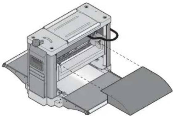
- The anti-chip guard is mounted in the rear of the planer and is fixed with the butterfly nuts.
Table Extensions Assembly
- The table extensions are factory aligned, however, can be misaligned with use.
- Adjust the two hex screws (A) that act as stoppers for both extensions (front and rear). Previously, loosen the safety nuts (B).
- Set one straight edge piece through the main table, and the extension to be adjusted to verify alignment.
Work Table and Cutter Head Alignment
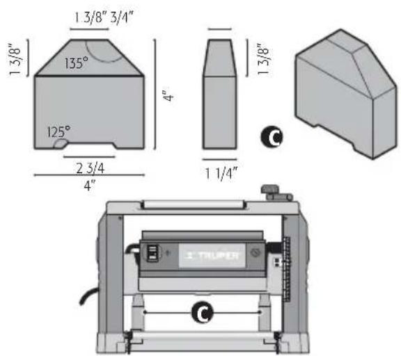
- Plan a wood piece and measure thickness after cutting. If the thickness is not even in both sides of the piece, is because the cutter head and the work piece are not properly aligned.
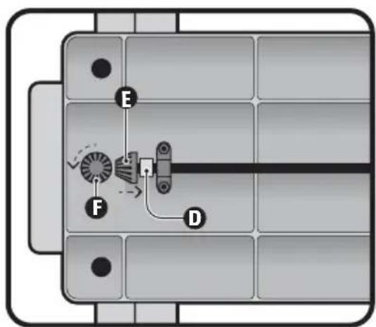
- To align, use two identical pieces of hard wood with the shape and measurements shown in the image (C) to level the cutter head with the table.
• Using care, lean the planer on its rear side.
• Under the main table, loosen the lock (D) horizontal cone gear (E). - Disengage the cone gears and turn the vertical cone gear (F) to adjust height in the appropriate side. Turning the gear one step of a tooth in a counter clockwise direction equals an increase of 0,05" planning thickness.
• After making adjustments, couple and secure the cone gears. - If necessary, repeat the procedure in the opposite side.
natural_image
3D technical illustration of a mechanical device with internal components and a curved arrow indicating rotation (no text or symbols)
Depth Scale Adjustment
- Feed a piece of scrap wood to plan (see page 10).
- Compare the measured thickness in the planned piece with the reading in the cutting depth scale.
- If there is no match, loosen the scale guide screws (G) and adjust to the thickness measurement in the planned piece.
- Test again using another piece of scrap wood and, if necessary, repeat the procedure until the measurement indicated in the scale guide matches the planned piece thickness.

Start Up
Turning ON
- The planer is built with a switch (H) with a safety key (REMOVE TO LOCK) to prevent unauthorized use. If not working with the machine for a long period of time and there is the possibility that third parties, especially children could use it, remove the safety key (REMOVE
TO LOCK) with the switch in the OFF position. Leave the key in a safe place. Do not lose it because you will not be able to use the planner. - To turn ON the planner, insert the safety key (REMOVE TO LOCK) and lift the switch in the ON position.
- To turn OFF the planner, lower the switch onto the OFF position.
WARNING • Double check the switch is in the OFF position before connecting the planer into the power supply.
Power Overload Protection
- The planer is built with an overload protection switch (I). If overloaded, the switch will trigger. To restart the motor, follow these steps:
1.- Set the switch (H) in the OFF position.
2.- Leave it cooling down at least 5 minutes.
3.- Press the overload protection switch (I).
4.- Set the switch (H) in the ON position to start the equipment.
NOTE: If the equipment shuts down again, please go to a
TRUPER Authorized Service Center.


Cutting Depth Adjustment
• Thickness in the work piece will depend on the distance of the cutter head and the work piece.
• To adjust the distance, turn the cutting depth control hand shank (J).
- The cutting depth adjustment can be read in the depth scale (K). The grading of the adjustment is 1/16" per hand shank turn.
- Always start the job making a light planning cut. Cutting depth in the subsequent steps may be increased up to 1/8". However, remember that a light cut produces a finer finish than a thick cut.
WARNING • Never carry out planning above 1/8" in one step. Neither try to work wood smaller than 5" long. Always wear protective face mask. Do not work on pieces with a thickness smaller than 3/16". Do not work pieces with a thickness greater than 6".

Feeding the Work Piece
- Feeding direction is pushing towards the planer front as indicated in the graph. Do not try to do it from the rear.
- Support the work piece on the table extension using both hands. Push the piece inside the planner. Do not take it off the table.
WARNING • Use care. Do not put hands inside the planer to avoid severe injuries.
- The outward pieces can be set on return rollers to return the pieces to the operator and facilitate making gradual cuts in the same piece.
CAUTION • Consider the following table to get a quality job and prevent accidents:
Feeding length (minimum): 5"
Feeding width (maximum): 12-1/2"
Feeding thickness: 0,2" - 6"
Cutting depth (maximum): 1/8"
Feeding speed: 26,2 fpm*
*(feet per minute)

natural_image
3D technical illustration of a mechanical assembly with wooden components and a dashed arc indicating motion (no text or symbols)Start Up
TRUPER®
For a good finish
• To get a good finish, make small consecutive cuts until getting the thickness you need.
- Feed the work piece with the wood fibers in the planer direction to gain a clean work and to prevent the fibers to get lifted or torn giving wood surface a hairy appearance.
- Feeding the piece in a transversal way can also cause big splinters to detach giving a very unpleasant appearance.
• Take notice of the piece depth and width, its harness, humidity, if is straight, direction and structure of grain. With time and experience, you will gain advantage of these factors.
• Work with pieces in good repair, without loose knots and with the least number of firm knots. When working with a new type of wood, carry out tests in scrap wood before working the final product.
- Every deep cut shall be made gradually. Move the depth control hand shank so that the cutter head descends no more than 1/8" and complete another step. Repeat this process until getting the desired depth.

Maintenance
WARNING Disconnect the power cable from the power supply before carrying out adjustments, service or maintenance in the machine.
- Accumulation of saw dust and other particles may cause the machine working with little precision. Periodic cleansing is not only advisable but mandatory to gain fine planning.
- Small parts like blocking bars wedges and the cutter head shall be cleaned with a brush and prevent foreign materials getting stuck and be possible to set them in their positions. Oil lightly those parts.
- Remove resin and other materials accumulated in the feeding rollers. Use a non-flammable solvent.
- Carbon brush replacement. Replace carbon bushes when their size of approximately 1/4" long. Both carbon brushes shall be replaced always at the same time.
Lubrication Service
- Lubrication recommended for the rollers' chains, running with a medium to low operation speed consists in only keeping the chains clean.
- When there is a considerable accumulation of dust and dirt, or wood shavings, cover the chain with a light film or oil. Never apply oil directly on the chain. Oil in excess may hinder the main purpose of lubrication because it accelerates the accumulation of dust, wood shavings, etc., and get into the chain grooves. This shortens the useful life of the chain leading to a premature replacement.
- This applies to speed reduction and chain height adjustment, as well as elevation screws.
- The cutter head bearings are factory lubricated and sealed. There is no need of further attention.
Servicing the machine shall only be carried out by certified personnel in a TRUPER Authorized Service Center. Service and maintenance carried out by non-certified personnel may result dangerous and can cause personal injuries and makes the Warranty void.
Problem Cause Solution
| Hairy finish. | ·Wood has too much humidity.·Dull blades. | ·Dry the wood.·Sharpen the blades. |
| Torn fibers. | ·Cut is too thick.·Blades cutting against the fibers.·Dull blades. | ·Check the right cutting depth.·Feed the wood piece in the fibers direction or turn around the piece 180°.·Sharpen the blades. |
| Rough or raised fibers. | ·Dull blades.·The cut is too thick.·High contents of humidity.·Damaged cutter head bearings. | ·Sharpen the blades.·Check the right cutting depth.·Dry the wood.·Go to a TRUPER Authorized Service Center to replace the bearings. |
| Poor wood feed. | ·The planer table is dirty.·Damaged feed rollers.·Damaged sprocket.·Damaged bearing box. | ·Remove dirt or residues. Lubricate table.·Go to a TRUPER Authorized Service Center.·Go to a TRUPER Authorized Service Center.·Go to a TRUPER Authorized Service Center. |
| Stuck work piece. | ·Incorrect blade height adjustment. | ·Adjust the blade to the right height. |
| Uneven cutting depth from side to side. | ·Misaligned blade.·The cutter head is misaligned to the table. | ·Adjust the blade.·Adjust the cutter head and the table. |
| The piece thickness in not matching the scale reading. | ·The cutting scale guide in not adjusted. | ·Adjust the cutting depth scale. |
| The chain jumps. | ·Misaligned sprockets.·Worn sprockets. | ·Align sprockets.·Go to a TRUPER Authorized Service Center |
| The machine does not start. | ·It is unplugged.·The protection switch fuse is broken.·Motor failure.·Loose connections.·Protection switch restarting. | ·Connect the plug.·Go to a TRUPER Authorized Service Center.·Go to a TRUPER Authorized Service Center.·Go to a TRUPER Authorized Service Center.·Allow the machine to cool down before starting again. |
| The motor stops repeatedly. | ·The power extension is too long or the gauge is low.·Dull blades.·Working with low voltage. | ·Use a shorter power extension or with a higher gauge.·Sharpen or replace the blades.·Verify the feeding voltage. |
In the event of any problem contacting a Service Center, please see our webpage www.truper.com to get an updated list, or call our toll-free numbers 01(800) 690-6990 or 01 (800) 018-7873 to get information about the nearest TRUPER Authorized Service Center.
AGUASCALIENTES
This product, its parts and components have a 1 year warranty against defects in its manufacture, operation and workmanship, except when: the product has been used in conditions other than those recommended, or has not been operated according to the instructions, or has been altered or repaired by personnel not authorized by ☑ TRUPER. In order to make the warranty valid or to purchase components and spare parts, you must present the product and its proof of purchase at Av. San Isidro #110, Col. Industrial San Antonio, ALC. Azcapotzalco, C.P. 02760, CDMX, Mex. or at the store where you bought it, or at a ☑ TRUPER service center listed in the attached warranty policy and/or at www.truper.com. Transportation costs resulting from compliance of this warranty will be covered by ☑ TRUPER. For questions or comments, call 01-800-690-6990.
Imported by: Truper, S.A. de C.V. Parque Industrial #1, Jilotepec, Edo. de Mex., Mex. C.P. 54240. Made in China.
Stamp of the business:

1 YEAR
Delivery date:
- Puesta en marcha
- TRUPER®
- Mantenimiento
- CAUTION
- Power Requirements
- Work area
- Electrical Safety
- Personal safety
- Power Tools Use and Care
- Service
- Before Operating the Tool
- While Operating the Tool
- After Operating the Tool
- Assembly
- Fixing the Planer to a Surface
- Blades Replacement and Mounting
- Anti-chip Guard Assembly
- Table Extensions Assembly
- Work Table and Cutter Head Alignment
- Depth Scale Adjustment
- Start Up
- Turning ON
- Power Overload Protection
- Cutting Depth Adjustment
- Feeding the Work Piece
- For a good finish
- Maintenance
- Lubrication Service
- AGUASCALIENTES
Brand : Truper
Model : CEP-12
Category : Angle Grinder