
SA808 - TV wall mount SANUS - Free user manual and instructions
Find the device manual for free SA808 SANUS in PDF.


| Product Type | TV Wall Mount |
| Model | SA808 |
| Brand | Sanus |
| Weight Capacity | Up to 50 lbs (22.7 kg) |
| VESA Compatible | 100x100mm to 400x400mm |
| Screen Size | 26" to 55" |
| Material | Steel |
| Profile | Low profile - 1.5" from wall |
| Level Adjustment | ±2° after installation |
| Installation Type | Fixed mount |
| Wall Plate Dimensions | 18.5" x 4.5" (470 x 114 mm) |
| Mounting Hardware | Included (screws, spacers, anchors) |
| Tools Required | Stud finder, drill, socket wrench (not included) |
| Safety Features | Secure locking mechanism, safety tested |
| Cleanability | Wipe with dry cloth |
| Warranty | 5 years |
| Compliance | UL listed |
Frequently Asked Questions - SA808 SANUS
User questions about SA808 SANUS
0 question about this device. Answer the ones you know or ask your own.
Ask a new question about this device
Download the instructions for your TV wall mount in PDF format for free! Find your manual SA808 - SANUS and take your electronic device back in hand. On this page are published all the documents necessary for the use of your device. SA808 by SANUS.
USER MANUAL SA808 SANUS
natural_image
Technical line drawing of a rectangular device with internal compartments and mounting points (no text or symbols)SA808 INSTRUCTION MANUAL
We'll Make It Stress-Free
If you have any questions along the way, just give us a call.
1-800-359-5520. We're ready to help!
Scan for more information
san.us/447

IMPORTANT SAFETY INSTRUCTIONS – SAVE THESE INSTRUCTIONS – PLEASE READ ENTIRE MANUAL PRIOR TO USE
Before getting started, let's make sure this product is perfect for you!
1
Will your accessories weigh more than 10 lb (4.5 kg)?

No—Perfect!
Yes— This product is NOT compatible. Visit Sanus.com or call 1-800-359-5520 [UK: 0800 056 2853] to find a compatible product.
2
What is your wall made of?

Drywall with wood studs
Perfect!

Unsure? Call 1-800-359-5520 [UK: 0800 056 2853]
3
Do you have all of the tools needed?


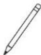


4
Ready to begin?
Please read through these instructions completely to be sure you're comfortable with this easy install process.
If you do not understand these instructions or have doubts about the safety of the installation, assembly or use of this product, contact Customer Service at 1-800-359-5520 [UK: 0800 056 2853].
CAUTION: Avoid potential personal injuries and property damage!
- Do not use this product outdoors
- This in-wall system is for use with ITE or Audio/Video equipment only
- The maximum specified ambient temperature of the cabinet system is 40o - 120oF (4o - 49oC)
- Do not use this product for any purpose not explicitly specified by manufacturer
● Manufacturer is not responsible for damage or injury caused by incorrect assembly or use
Supplied Parts
⚠ WARNING: This product contains small items that could be a choking hazard if swallowed.
Before starting assembly, verify all parts are included and undamaged. If any parts are missing or damaged, do not return the damaged item to your dealer; contact Customer Service. Never use damaged parts!


STEP 1 Cut Hole for Housing
CAUTION: Avoid potential personal injuries and property damage!
- Drywall covering the wall must not exceed 16 mm (5/8 in.).
- Box must be mounted between studs that are at least 406 mm (16 in.) apart. After installation there will not be enough space between the SA808 and the studs for electrical wires/cables, plumbing, ductwork, or insulation. Choose your SA808 location carefully.
- Locate the studs using an edge-to-edge stud finder. Verify the edges of the studs using an awl or thin nail. Mark the inner edges of the studs with pencil.
- The open area on the left of the template 01 should line up the the inner edge of the left stud. This will allow space for the placement of a power box on the right side of the housing 02. Level the template 01 and use a pencil to mark the open area of the template 01.


STEP 1 Cut Hole for Housing cont.
- Use a drywall saw or similar tool to cut the drywall where marked. Remove cut section of drywall.
WARNING! ELECTRICAL SHOCK HAZARD! CUTTING OR DRILLING INTO ELECTRICAL WIRES OR CABLES CAN CAUSE DEATH OR SERIOUS PERSONAL INJURY! Always make certain the area behind mounting surfaces is free of electrical wires and cables before cutting, drilling, or installing fasteners.
WARNING! EXPLOSION AND FIRE HAZARD! CUTTING OR DRILLING INTO GAS PLUMBING CAN CAUSE DEATH OR SERIOUS PERSONAL INJURY! Always make certain the area behind mounting surfaces is free of gas, water, waste, or any other plumbing before cutting, drilling, or installing fasteners.
4. Install wires and cables.
natural_image
Technical illustration of a cable being inserted into a housing, with an inset showing the same component (no text or symbols present)
natural_image
Diagram of an electrical component mounted on a wall, showing a connected cable and connector (no text or symbols present)STEP 2 Install Housing
- Break out the sections of the housing 02 that are required to install the power and cable outlets that are needed.
NOTE: Knockouts are provided for ease of installation. Any unused knockouts that have been punched are to be closed up with a metal plug. - Thread the elastic-velcro strap into the housing 02.
1
natural_image
Technical line drawing of a mechanical device with internal components and labeled section '02' (no text or symbols beyond label)2
STEP 2 Install Housing cont.
- Optionally, install a UL Listed 120 VAC electrical outlet box (not included) capable of attaching to the SA808 housing 02 following the instructions included with the outlet box. Slide cables and additional wires through the hole in the bottom of the housing 02 and the rubber cable grommet 04. Fit the cable grommet 04 into the hole.
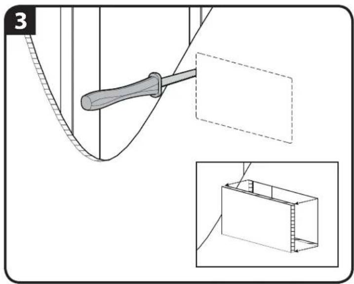
- Using a screwdriver, turn the screws in the corners of the housing 02. These will raise the locking tabs in the rear of the housing 02 to secure it to the wall. Tighten only until secure. Do not over-tighten screws.


STEP 3 Install Components
ECO-Mini (purchased separately) with the SA808 - Optional
NOTE: Minimum spacings between the accessories and components and the housing for Information Technology Communication Equipment shall be maintained for safe operation of the equipment when installed in accordance with the National Electric Code, ANSI/NFPA 70-1999. Refer to communication equipment manufacturer's specifications for minimum spacings.
- To use the ECO-Mini (purchased separately) in the SA808, first remove feet.
- Fit the ECO-Mini into the ECO-Mini bracket 05 supplied with the SA808.

natural_image
Mechanical assembly diagram showing a screwdriver inserted into a rectangular housing with mounting holes (no text or symbols)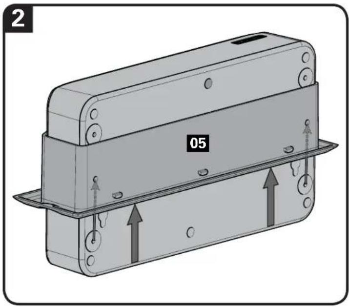
STEP 3 Install Components cont.
ECO-Mini (purchased separately) with the SA808 - Optional
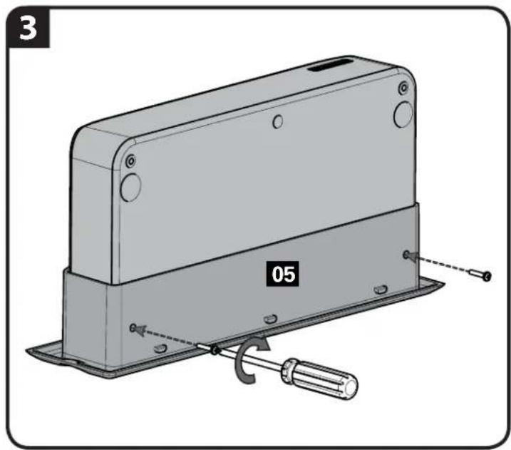
- Use two of the screws from the feet to secure the ECO-Mini in the bracket 05.
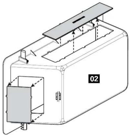
- Slide the ECO-Mini and bracket 05 into the top of the housing 02. Lock the bracket 05 into the housing 02 by sliding it towards the corner until you feel it catch.
natural_image
Technical illustration of a mechanical device with labeled components and a tool (no text or symbols beyond labels)
STEP 3 Install Components cont.
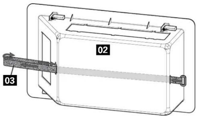
- Use the elastic-velcro strap 03 to attach components to the housing 02.
- Power the ECO-Mini with the power cord supplied with the ECO-Mini.
5

6

Positioning
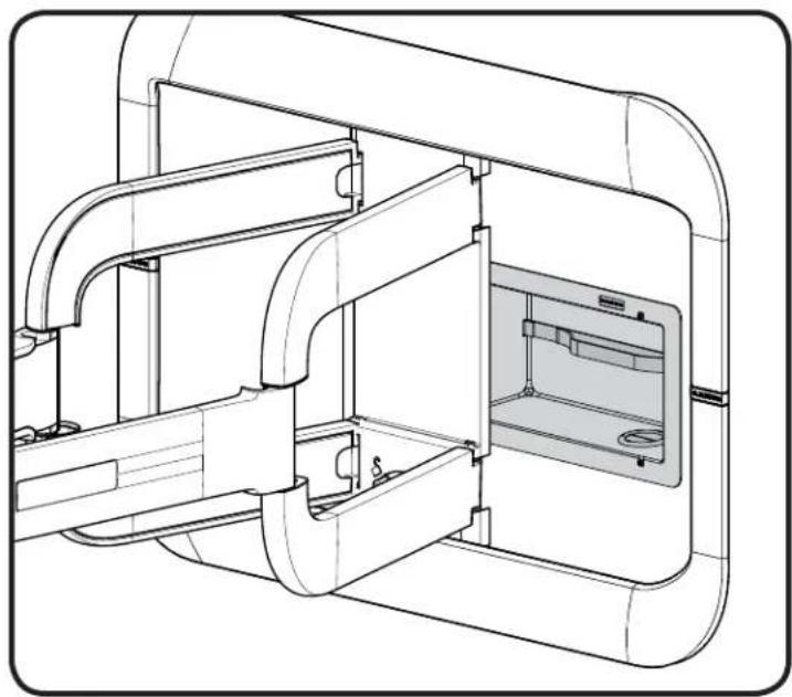
The SA808 can be installed behind most large wall plates of wall mounts or underneath or above most small wall plates. To access the SA808 after installation, disconnect all cables and wires from the TV, then either slide or remove the arm or TV mount from the wall plate.
IMPORTANT: Check your TV owner's manual to see if there are any special requirements for mounting or removing your TV.
natural_image
Technical line drawing of a mechanical assembly with internal components (no text or symbols)
natural_image
Technical line drawing of a mechanical assembly with no visible text or symbolsDimensions
![4.00 in. [101.6 mm] ECO SYSTEM ASM 125°](/content/2026/05/829785/images/ddf7369fb2166878b957bf7796b8b213bb3fecd8a70313f01b6c4d2e5d9606cc.jpg)
![7.80 in. [198.1 mm] 5.84 in. [148.4 mm] 11.80 in. [299.8 mm] 13.80 in. [350.5 mm]](/content/2026/05/829785/images/82836ddf592b39865237a001ce2bcffa7bf9dc9b7af284c503c9f6a213615f7f.jpg)
ESPAÑOL
Thank you for choosing Sanus! Please take a moment to let us know how we did:

Call us: 1-800-359-5520
UK: 0800 056 2853

Email us: info@sanus.com Leave a review: sanus.com

Find us on Facebook: SANUS Follows on Twitter @sanussystems
Milestone AV Technologies and its affiliated corporations and subsidiaries (collectively, "Milestone"), intend to make this manual accurate and complete. However, Milestone makes no claim that the information contained herein covers all details, conditions, or variations. Nor does it provide for every possible contingency in connection with the installation or use of this product. The information contained in this document is subject to change without notice or obligation of any kind. Milestone makes no representation of warranty, expressed or implied, regarding the information contained herein. Milestone assumes no responsibility for accuracy, completeness or sufficiency of the information contained in this document.
©2013 Milestone AV Technologies. All rights reserved. Sanus is a division of Milestone.
All other brand names or marks are used for identification purposes and are trademarks of their respective owners.
SANUS • 6436 City West Parkway • Eden Prairie, MN 55344 USA
6901-002315 01


- SA808 INSTRUCTION MANUAL
- We'll Make It Stress-Free
- IMPORTANT SAFETY INSTRUCTIONS – SAVE THESE INSTRUCTIONS – PLEASE READ ENTIRE MANUAL PRIOR TO USE
- Supplied Parts
- STEP 1 Cut Hole for Housing
- STEP 1 Cut Hole for Housing cont.
- STEP 2 Install Housing
- STEP 2 Install Housing cont.
- STEP 3 Install Components
- ECO-Mini (purchased separately) with the SA808 - Optional
- STEP 3 Install Components cont.
- Positioning
- Dimensions
- ESPAÑOL
Brand : SANUS
Model : SA808
Category : TV wall mount