
VMD1 - TV wall mount SANUS - Free user manual and instructions
Find the device manual for free VMD1 SANUS in PDF.


| Brand | SANUS |
| Model | VMD1 |
| Product Type | Single Monitor Arm (Desk Mount) |
| Weight Capacity | 25 lbs (11.34 kg) per arm |
| Mounting Type | Clamp (edge mount) |
| Maximum Desk Thickness | 5/8" (1.6 cm) |
| Adjustments | Head tilt (continuous), height (counterbalance), pivot (+/-90°), portrait (+/-90°) |
| Cable Management | Built-in channels with snap-on covers (upper and lower arm) |
| Quick Release Faceplate | Yes, with security tab |
| Included Hardware | M4x14mm screws (4), M4x25mm screws (4), M10x5.3x10 spacers (4), 3/16" hex key, 1/8" hex key |
| Tools Required (not included) | #2 Phillips screwdriver |
| Materials | Steel and aluminum |
| Color | Black (typical) |
| Height Adjustment Range | Not specified; uses counterbalance tension |
| Pivot Range | +/-90° from center |
| Portrait Rotation | +/-90° |
| Warranty | 5-year limited (typical for Sanus) |
| Compliance | Not specified |
Frequently Asked Questions - VMD1 SANUS
User questions about VMD1 SANUS
0 question about this device. Answer the ones you know or ask your own.
Ask a new question about this device
Download the instructions for your TV wall mount in PDF format for free! Find your manual VMD1 - SANUS and take your electronic device back in hand. On this page are published all the documents necessary for the use of your device. VMD1 by SANUS.
USER MANUAL VMD1 SANUS
INSTALLATION INSTRUCTIONS
Sanus
6436 City West Parkway
Eden Prairie, MN 55344 USA
Customer Service
Americas: 800-359-5520 • 952-225-6013 • info@sanus.com
Europe, Middle East, and Africa: +31 40 2324700 • europe.sanus@milestone.com
Asia Pacific: 86 755 8996 9226 • sanus.ap@milestone.com
www.sanus.com
DISCLAIMER
Milestone AV Technologies and its affiliated corporations and subsidiaries (collectively "Milestone"), intend to make this manual accurate and complete. However, Milestone makes no claim that the information contained herein covers all details, conditions or variations, nor does it provide for every possible contingency in connection with the installation or use of this product. The information contained in this document is subject to change without notice or obligation of any kind. Milestone makes no representation of warranty, expressed or implied, regarding the information contained herein. Milestone assumes no responsibility for accuracy, completeness or sufficiency of the information contained in this document.
Milestone AV Technologies, a Duchossois Group Company. All rights reserved. Sanus is a division of Milestone. All other brand names or marks are used for identification purposes and are trademarks of their respective owners.

IMPORTANT WARNINGS AND
CAUTIONS!

WARNING: A WARNING alerts you to the possibility of serious injury or death if you do not follow the instructions.

CAUTION: A CAUTION alerts you to the possibility of damage or destruction of equipment if you do not follow the corresponding instructions.

WARNING: Failure to read, thoroughly understand, and follow all instructions can result in serious personal injury, damage to equipment, or voiding of factory warranty! It is the installer's responsibility to make sure all components are properly assembled and installed using the instructions provided.

WARNING: Failure to provide adequate structural strength for this component can result in serious personal injury or damage to equipment! It is the installer's responsibility to make sure the structure to which this component is attached can support five times the combined weight of all equipment. Reinforce the structure as required before installing the component. The wall to which the mount is being attached may have a maximum drywall thickness of 5/8" (1.6cm).

WARNING: Exceeding the weight capacity can result in serious personal injury or damage to equipment! It is the installer's responsibility to make sure the combined weight of all components located between the VMD1 Monitor Arm up to (and including) the display does not exceed 25 lbs (11.34 kg) per arm. Use with products heavier than the maximum weight indicated may result in collapse of the mount and its accessories causing possible injury.
DIMENSIONS
VMD1


LEGEND
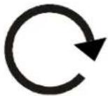 | Tighten Fastener |
| Apretar elemento de fijación | |
| Befestigungsteil festziehen | |
| Apertar fixador | |
| Serrare il fissaggio | |
| Bevestiging vastdraaien | |
| Serrez les fixations | |
 | Loosen Fastener |
| Aflojar elemento de fijación | |
| Befestigungsteil lösen | |
| Desapertar fixador | |
| Allentare il fissaggio | |
| Bevestiging losdraaien | |
| Desserrez les fixations | |
 | Phillips Screwdriver |
| Destornillador Phillips | |
| Kreuzschlitzschraubendreher | |
| Chave de fendas Phillips | |
| Cacciavite a stella | |
| Kruiskopschroevendraaier | |
| Tournevis à pointe cruciforme | |
 | Open-Ended Wrench |
| Llave de boca | |
| Gabelschlüssel | |
| Chave de bocas | |
| Chiave a punte aperte | |
| Steeksleutel | |
| Clé à fourche | |
 | By Hand |
| A mano | |
| Von Hand | |
| Com a mão | |
| A mano | |
| Met de hand | |
| À la main | |
 | Hex-Head Wrench |
| Llave de cabeza hexagonal | |
| Sechskantschlüssel | |
| Chave de cabeça sextavada | |
| Chiave esagonale | |
| Zeskantsleutel | |
| Clé à tête hexagonale |





Pencil Mark
Marcar con lápiz
Stiftmarkierung
Marcar com lápis
Segno a matita
Potloodmerkteken
Marquage au crayon
Drill Hole
Perforar
Bohrloch
Fazer furo
Praticare un foro
Gat boren
Percez un trou
Adjust
Ajustar
Einstellen
Ajustar
Regolare
Afstellen
Ajuster
Remove
Quitar
Entfernen
Remover
Rimuovere
Verwijderen
Retirez
Optional
Opcional
Optional
Opcional
Opzionale
Optie
En option
Security Wrench
Llave de seguridad
Sicherheitsschlüssel
Chave de segurança
Chiave di sicurezza
Veiligheidssleutel
Clé de sécurité
TOOLS REQUIRED FOR INSTALLATION

PARTS
![A (1) [monitor arm] B (4) M4x14mm C (4) M4x25mm D (4) M10x5.3x10 E (1) 3/16" F (1) 1/8"](/content/2026/05/900980/images/05fd1250f47249eafd4955dc466d2d9db59387bb6d332b769b5cf8b630cad3b9.jpg)
Connecting VMD1 to Desk
- Loosen clamp screw until enough space is created between clamp and mount to allow for desk mounting. (See Figure 1)
NOTE: If space is limited behind desk (i.e. against wall, etc.), remove clamp entirely in Step 1 and reattach clamp prior to Step 3!
-
Place mount on top of desk at desired mounting location. (See Figure 1)
-
Tighten clamp using clamp screw until mount is securely fastened to desk. (See Figure 1)
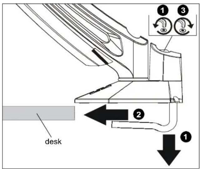
Figure 1
Display Installation
- Remove quick release faceplate from mount by pressing quick release tab and sliding faceplate off mount. (See Figure 2)

Figure 2

WARNING: Only remove display from mount when the display can be lifted up from the mount! DO NOT remove display unless the display is in the upright position! See Display Removal section for details.
- Carefully place display face down on protective surface.
- Connect faceplate to display
For flush mounting hole installation:
- Using Phillips screwdriver, carefully install four M4x14mm screws (B) through corresponding holes on faceplate and into the mounting holes on the display. (See Figure 3)

Figure 3
For recessed mounting hole installation:
- Place four spacers (D) on top of mounting holes on back of display. (See Figure 9)
- Using Phillips screwdriver, carefully install four M4x25mm screws (C) through corresponding holes on faceplate, spacers (D) and into the mounting holes on the display. (See Figure 4)

Figure 4
- Position display with faceplate attached above mount. (See Figure 5)
- Slide faceplate onto mounting head until quick release tab clicks into place. (See Figure 5)

Figure 5
Adjustments
Head Tilt Adjustment
- Adjust head tilt to desired tilt position. (See Figure 6)
- Adjust head tilt tension screw to change the adjustment tension. (See Figure 6)
Height Adjustment

CAUTION: OVERTENSIONING THE HEIGHT-ADJUSTMENT TENSION SCREW MAY CAUSE DAMAGE! Do NOT overtighten height-adjustment tension screw when adjusting tension for lighter or heavier displays.
- Adjust arm height to desired level. (See Figure 6)
- Open cable management cover on upper arm to expose height-adjustment tension screw. See Cable Management section for details.
- Use 1/8" hex key (F) to adjust height-adjustment tension screw to change adjustment tension. (See Figure 6)
NOTE: Turn clockwise to reduce tension for lighter displays and counter-clockwise to increase tension for heavier displays.
Pivot Adjustment
- Adjust pivot position as desired. (See Figure 6)
- Use 3/16" hex key (E) to adjust pivot point tension screws to change pivot adjustment tension. (See Figure 6)

Figure 6
Pivot Adjustment Range
- Adjust arm angle as desired up to 90 degrees in either direction. (See Figure 7)

WARNING: Swinging the arm beyond 90 degrees may result in the mount slipping off the desk causing serious injury!
(6901-002123 <01>)

Figure 7
Portrait Adjustment
- The monitor may be adjusted 90 degrees in either direction in order to provide a portrait view of the monitor. (See Figure 8)

Figure 8

WARNING: Only remove display from mount when the display can be lifted up from the mount! DO NOT remove display unless the display is in the upright position! See Display Removal section for details.
Cable Management
- Use screwdriver to unhinge tab on either end of cable management cover on upper arm. (See Figure 9)
- Slide screwdriver along edge of cover until remaining tabs are unhinged and cover is in the "open" position. (See Figure 9)

Figure 9

Figure 10
- Route cables through cable management channels. (See Figure 10)
IMPORTANT! Be sure to leave enough slack in the cables near display and arm joint to allow for full arm articulation!
-
Close cable management covers on monitor arm. (See Figure 10)
-
Repeat Steps 1-4 for lower arm.
Display Removal

WARNING: Only remove display from mount when the display can be lifted up from the mount! DO NOT remove display unless the display is in the upright position! (See Figure 11)
- Make sure display is in the upright position.
- Remove quick release faceplate from mount by pressing quick release tab and sliding faceplate off mount. (See Figure 11)
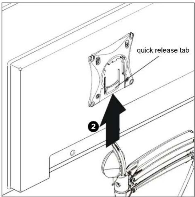
Figure 11


- INSTALLATION INSTRUCTIONS
- DISCLAIMER
- IMPORTANT WARNINGS AND
- CAUTIONS
- DIMENSIONS
- LEGEND
- PENCIL MARK
- DRILL HOLE
- ADJUST
- REMOVE
- OPTIONAL
- SECURITY WRENCH
- CONNECTING VMD1 TO DESK
- DISPLAY INSTALLATION
- ADJUSTMENTS
- HEAD TILT ADJUSTMENT
- HEIGHT ADJUSTMENT
- PIVOT ADJUSTMENT
- PIVOT ADJUSTMENT RANGE
- PORTRAIT ADJUSTMENT
- CABLE MANAGEMENT
- DISPLAY REMOVAL
Brand : SANUS
Model : VMD1
Category : TV wall mount