
Juwel 1 - Slicer ADE - Free user manual and instructions
Find the device manual for free Juwel 1 ADE in PDF.


| Brand | ADE |
| Model | Juwel 1 |
| Type | Straight Feed Slicer |
| Blade Diameter | 250 mm |
| Cutting Thickness Range | 0–15 mm |
| Cutting Area | 220 × 175 mm |
| Dimensions (W × D × H) | 530 × 630 × 400 mm |
| Net Weight | 23 kg |
| Packaging Dimensions | 760 × 660 × 580 mm |
| Power Supply (Standard) | 230 V / 0.21 kW, 50/60 Hz |
| Power Supply (Optional) | 400 V / 0.27 kW, 50/60 Hz |
| Fuse Recommendation | 0.5 Amp in power supply box |
| Blade Rotation (Viewed from guard side) | Anticlockwise |
| Intended Use | Slicing cooked/raw charcuterie, warm/cold meats, bread, cheese, stoneless fruits & vegetables |
| Not Suitable For | Frozen goods, bone-in meat, stone fruits |
| Operating Mode | Continuous commercial use |
| Controls | Start (I) and Stop (O) buttons with white indicator lamps; safety switch in blade guard |
| Safety Features | Fixed blade guard, product carriage lock, no-voltage relay, blade removal tool required |
| Cleaning | Daily disassembly; wash with warm water & mild detergent; disinfect with alcohol; no abrasive or bleach-based cleaners |
| Lubrication | Vaseline oil (e.g., MARCOL 82) applied sparingly and frequently on carriage slides |
| Blade Sharpening | Only via supplied sharpening device; for smooth blades only; toothed blades by specialist |
| Warranty | 2 years (defects in material or workmanship; wear parts excluded) |
| Certifications | CE, Machinery Directive 2006/42/EC, EMC 2014/30/EU, Low Voltage 2014/35/EU, RoHS 2011/65/EU |
| Spare Parts Availability | Listed in manual with part numbers for Juwel 1 |
Frequently Asked Questions - Juwel 1 ADE
User questions about Juwel 1 ADE
0 question about this device. Answer the ones you know or ask your own.
Ask a new question about this device
Download the instructions for your Slicer in PDF format for free! Find your manual Juwel 1 - ADE and take your electronic device back in hand. On this page are published all the documents necessary for the use of your device. Juwel 1 by ADE.
USER MANUAL Juwel 1 ADE
Straight Feed Slicers

natural_image
Exterior view of a silver ADE cutlotype solar watermelon maker (no text or symbols visible)Series JUWEL
Juwel-210614-Rev011-UM-en
CONTENT
- FOREWORD....2
- INTENDED USE 2
- FIGURES.... 3
- PREPARATION AND OPERATION 4
4.1 Opening the packaging 4
4.2 Installation....5
4.3 Wiring....5
4.4 Operation 5 - CONTROLS AND SAFETY DEVICES 6
5.1 Controls 6
5.2 Mechanical safety devices 6
5.3 Testing 6 - USING THE SLICER....7
6.1 Operating procedure 7 - MAINTENANCE AND CARE OF THE SLICER....7
7.1 Cleaning....7
7.2 Lubricating 8 - SHARPENING OPERATIONS 8
8.1 Sharpening blade....9 - CLEANING AND MAINTENANCE 9
- TRAINING.... 10
- WARRANTY 10
- TECHNICAL FEATURES.... 11
- CE – Declaration of conformity.... 12
- WIRING DIAGRAMS.... 13
- EXPLODED VIEWS.... 14
- SPARE PARTS SERIES JUWEL 20
1. FOREWORD

This symbol means: "Consult operating instructions". Read the instructions for use carefully before use and follow all instructions provided therein. Keep the instructions for use for future reference.
This manual has been compiled in conformity with the Machine Directive in the latest version. With it, the manufacturer intends to furnish the customer with clear and concise instructions for the use and maintenance of the machine, as well as information regarding the safety devices with which it is fitted in order to assure maximum efficiency throughout its service life.
The slicers may be updated; this eventuality shall not prejudice the explanations contained in the manual.
Before starting up the slicer, you are advised to read this manual carefully.
Should this manual be damaged or lost, apply for a copy from the manufacturer without delay.
Many accidents are the result of insufficient familiarity with the machine and its safety devices. Before starting work, read the instructions herein carefully and follow them to the letter.
The Vertical slicers have been designed to comply with the provisions of the European community safety regulations. Consequently, each slicer is fitted with a plate featuring the “CE” mark attesting to the product’s conformity with said provisions.
2. INTENDED USE
These slicers have been manufactured to slice:
- cooked and raw charcuterie,
- warm and cold meats,
- bread and cheese,
- stoneless fruit and vegetables.
The machine is intended for continuous operation in commercial gastronomic applications. They can slice thicknesses up to 15mm.

They are not suitable for cutting frozen goods, charcuterie and meat on the bone or fruit with stones.
Any attempt to slice said products or similar foods may result in serious damage to the machine and shall cause the warranty to become void.
- FIGURES
4. PREPARATION AND OPERATION
On receiving the box containing the slicer, make sure that it is intact and has not been damaged during transit.
4.1 Opening the packaging
- Cut and remove the plastic straps;
- Remove the metal staples;
- Lift the box off vertically, locate the user guide, maintenance manual and the four feet;
- Using a 6mm spanner, unscrew the bolts securing the machine to the pallet;
- Remove the polyethylene bag and screw on the four feet;
- Lift the machine: two people are required to handle the machine, using the feet as handholds;
- Check the contents of the packaging, making sure they correspond to the specifications on the documents;

Packaging material are recyclable material and may be disposed of under no circumstance in the house case.
Please ask the public authorities about possibilities of a proper disposal.
The local regulations have to be absolutely adhered at the disposal.
The packing material may not be disposed of in free nature.

4.2 Installation
Place the slicer on a smooth, flat and stable surface.
Any unevenness of the surface on which the machine is rested can be compensated using the adjustable feet.
In the event the motor ventilation area faces a wall, make sure that a space of at least 200mm is left between it and the wall.
Leave enough room around the slicer so that it can be properly operated, cleaned and serviced.
It is advisable to leave a space of at least 300mm free around the machine.
The slicer works properly in places with a relative humidity level of less than 80% and near sources of heat of no more than 30°C.
4.3 Wiring
Plug the machine into the outlet, making sure that the system features an electrical overload cutout. To improve safety further, insert a 0.5 Amp fuse in the power supply box.
The blade should rotate anticlockwise seen from the blade guard side.
Should the direction of rotation of the three-phase slicers be incorrect, invert two of the three wires in the plug.
4.4 Operation
Use the slicer as it was designed to be used. Never push the product towards the blade by hand. Keep hands well away from the blade and use the relevant handle to move the product carriage safely back and forth.
5. CONTROLS AND SAFETY DEVICES
5.1 Controls
The Vertical slicers are switched on and off electrically by means of two buttons, I (start) and O (stop). Both feature a white lamp which indicates when the blade is rotating.
The machine features a safety switch in the blade guard connected with a no voltage relay. Every time the supply voltage is cut off, the button "I" (start) must be pressed to start the machine up again.
5.2 Mechanical safety devices
- With the exception of the actual cutting section, the blade is totally protected by an irremovable guard which cannot be removed.
- The product carriage can only be removed if the slice assembly covers the blade and the graduated knob is set to "0" (zero).
- The slice assembly can only be opened (using the graduated knob) if the product carriage is secured in its normal operating position.
- The blade can only be removed using the blade-removal tool supplied.
- None of the safety devices can be removed; dismantling or tampering with them would make the machine unsafe, and result in the manufacturer no longer being responsible for any accidents.
5.3 Testing
- Make sure all the slicer components are assembled properly.
- Check the handwheel securing the blade guard is locked in place.
- Press the start button and check the machine can be switched on and off.
- Check the sliding of the product carriage and product press.
- Check the sharpening device works properly.
- Check the opening of the slice assembly.
6. USING THE SLICER
6.1 Operating procedure
(Fig.1)
1) Set the graduated knob "A" to "0" (zero).
2) Move the product carriage "B" as far away from blade "K" as possible.
3) Lift the product press "C" using the relevant handle.
4) Set the product down on the product carriage, lower the product press onto or behind the product.
5) Select the desired thickness by means of knob "A".
6) Press the button "I" (start).
7) Push the product carriage to slice the product by means of handle "D".
8) Once you have finished using the machine, switch it off by pressing the "O" (stop) button and set the graduated knob to "0".

The product carriage must not be operated by holding the hand guard (Fig. 1)! There is a risk of injury!

natural_image
Close-up of a hand operating a mechanical device with red prohibition signs (no text or symbols on the device itself)Picture 1: Unintended Use!

natural_image
Close-up of a hand using a lathe machine to cut or install a tray, with arrows indicating motion direction (no text or symbols visible)Picture 2: Intended Use
7. MAINTENANCE AND CARE OF THE SLICER
For the sake of hygiene, the slicer must be kept clean.
The machine must be disassembled and cleaned at the end of each working day, and whenever the type of product being sliced is changed (e.g. change from raw meats to cooked meats) following the sequence illustrated in fig. 2.
7.1 Cleaning
(Fig. 2 and Fig. 4)
1) Isolate the machine from the power supply by unplugging it, or switching off the automatic switch located near the outlet. Never settle for simply pressing the slicer's "O" button.
2) Set the graduated knob "A" from "15" to "0" and to clip sth (Fig. 4, site 3).
3) Unscrew handwheel "Q" completely in any position.
4) With a relatively firm jerk, pull the product carriage towards the stop "R" towards torso so that the locking mechanism engages.
Slide the product carriage unit vertically from its guide. The slice assembly remains locked in the "0" position.
5) Unscrew the fastening handwheel "D" completely, hold the blade guard "K" and remove it from the machine completely.
6) Unscrew knob "H" by three turns.
7) Lift the sharpening device using handle "V" and slide it from its seat.
8) Position the blade-removal tool "J" in place and fasten it onto the threaded holes by means of the two handwheels "W". Use a screwdriver to unscrew the 4 blade screws, after which use the two handwheels to remove the assembly.
9) Clean the removed blade with warm water and liquid detergent, rinse in clear water, dry and use alcohol to disinfect.
The base and other parts of the machine must always be washed with some lukewarm water and liquid detergent, and rubbed with a non-abrasive cloth; rinse with a cloth and some clear water, dried out and use alcohol to disinfect.
Under no circumstances use sodium-hypochlorite-based solutions or abrasive detergents as they would damage the machine's anodized surfaces.
10) Wait with fitting until all parts are dried. Otherwise there's risk for rust formation.
11) The machine is fitted back together by following the disassembly procedure in reverse order.

Warning: the blade guard represents a very important safety device and must only be removed when the blade is fastened in its regular position by means of the four screws.
7.2 Lubricating
(Fig. 3)
In order to keep the product press and carriage sliding movements fluid, the slicer must be lubricated regularly in the points highlighted in fig. 3; use Vaseline oil only (e.g. MARCOL 82 ESSO or WHITE OIL 105 BERGOIL), apply sparingly but frequently.
8. SHARPENING OPERATIONS
The cutting blade must always be kept well sharpened in order to ensure problem-free operation of the machine. It should be noted that regular 'short' sharpening is to be preferred over more extensive operations.
Always ensure that before starting with this type of operation, the graduated knob for adjusting the cut thickness has been set to "0".

Sharpening is only to be carried out on smooth blades; toothed blades for bread cutting machines must be sharpened by specialist companies.

Cutting blades should only be sharpened when they are clean and completely free of grease, as grinding a blade which has grinding waste stuck to it can not only cause damage to the sharpening machine but also its grinding wheels.
Any dirt deposits remaining on the grinding wheels after sharpening a blade should be removed. In addition, any grains of sand remaining on a cutting blade or on the machine must be removed using a cloth dipped in alcohol.
8.1 Sharpening blade
1) Switch off the machine.
2) Remove the grease from the blade both inside and out using a cloth dampened with alcohol.
3) Turn the slice thickness adjusting knob to the left in anticlockwise direction up to the stop.
4) Unscrew completely the black turning knob of the sharpening device supplied with each machine with standard knife. Then lead the end of the thread visible now through the hole of the thickness-plate from the side of the carriage, while pulling the last-slice-device a bit upwards to the right.
Then screw on the sharpening device by means of the turning knob in such a way the neck of the sharpening device rests upon the upper edge of the thickness plate.
5) Switch on the motor and advance the sharpening wheel carefully with not too much expenditure of force to the rotating blade by turning slightly to the right the slice thickness adjusting knob. The contact must be affected in such a way that the sharpening wheel is also turning. Normally a few seconds are sufficient to sharpen the blade in this manner.
6) Having finished sharpening, switch off the motor, take off the sharpening device and adjust the slice thickness to zero again.
7) Clear blade and shaft of the last-slice-device thoroughly of adhering sharpening shavings with a cloth.
As the blade will not always be entirely free from fat, it is recommendable to clean the sharpening wheel with pure benzene from time to time.

The sharpening operation must be performed by skilled personnel.
Never attempt to clean the blade whilst it is moving.
The sharpening device can no longer sharpen the blade once its diameter is worn down by 10mm.
9. CLEANING AND MAINTENANCE
- The machine must be cleaned by fully trained personnel only.
- Unplug the machine. Never stop the machine using the (stop) button only.
- Two people are required to handle the machine, using the 4 feet as handholds.
- The blade must be replaced when the distance between the blade guard and the actual blade is no more than 6mm.
- Only remove the blade using the proper blade-removal tool.
- Be careful with the blade edge as it is very sharp.
-
The power supply cable must be replaced by skilled personnel only.
-
The cleaning of the slicer with harmful products liable to affect the health of either operators or customers is strictly prohibited.
- Use products with a degree of acidity (pH 7 - 8).
10. TRAINING
- During the machine's installation, it is absolutely essential that an operator of age be trained in the regular use-cleaning-care-sharpening of the blade, especially regarding the hazards which are likely to be encountered if the machine is used incorrectly.
- The training will be given by studying the operating manual very careful.
11. WARRANTY
ADE will repair or replace this product within a period of 2 year from date of delivery applying to defects occurred due to poor material or workmanship (invoice is necessary).
All moveable parts are excluded. The warranty does not include natural ear, damages caused by incorrect or negligent handling, overuse or unsuitable or improper storage.
The manufacturer refuses each direct or indirect responsibility of the following circumstances:
- Disregarding of instruction
- Usage by untrained personnel that is not familiar with the instruction
- Usage that does not correspond to the valid prescriptions
- Non authorized modification or repair
- Usage of equipment and accessories that is not from manufacturer's origin
The legal rights of the customer are not hindered by the agreement of this warranty.
In case of registering a complaint, contact the dealer that has sold the product.
12. TECHNICAL FEATURES
Model Juwel 1 Juwel 2K
Blade ∅ 250 mm 300mm
Variable adjustment 0-15mm 0-15mm
Cutting area 220 x 175 mm 220 x 215 mm
Dimensions 530 x 630 x 400 mm 550 x 650 x 470 mm
Type of current / Power rating 230 V / 0.21 kW 230 V / 0.21 kW
Type of current / Power rating 400 V / 0.27 kW 400 V / 0.27 kW
Dead weight 23 kg 29 kg
Packing dimensions 760 x 660 x 580 mm 760 x 660 x 580 mm
Model Juwel 2 Juwel 3
Blade ∅ 300mm 350mm
Variable adjustment 0-15mm 0-15mm
Cutting area 280 x 215 mm 280 x 270 mm
Dimensions 650 x 780 x 470 mm 650 x 780 x 530 mm
Type of current / Power rating 230 V / 0.27 kW 230 V / 0.27 kW
Type of current / Power rating 400 V / 0.37 kW 400 V / 0.37 kW
Dead weight 39 kg 42 kg
Packing dimensions 850 x 660 x 690 mm 850 x 660 x 690 mm
13. CE – Declaration of conformity
CE
Declaration of conformity by the manufacturer
This product has been manufactured in accordance with the harmonised European standards.
They conform to the regulations of the EC-directives listed below:
– Machinery Directive 2006/42/EC
- EMC Directive 2014/30/EU
– Low Voltage Directive 2014/35/EU
– RoHS Directive 2011/65/EU
in the currently valid versions.
This declaration loses its validity if modifications are made to the scale without our approval.
Hamburg, June 2021
ADE Germany GmbH
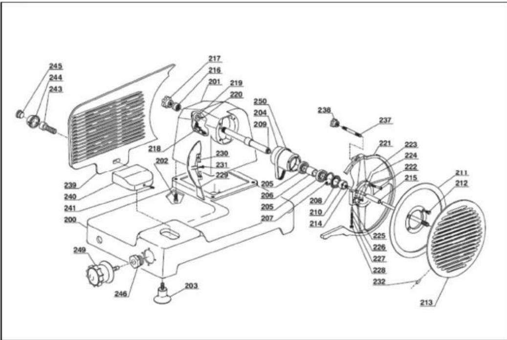
SOCKET Juwel 2 + Juwel 3
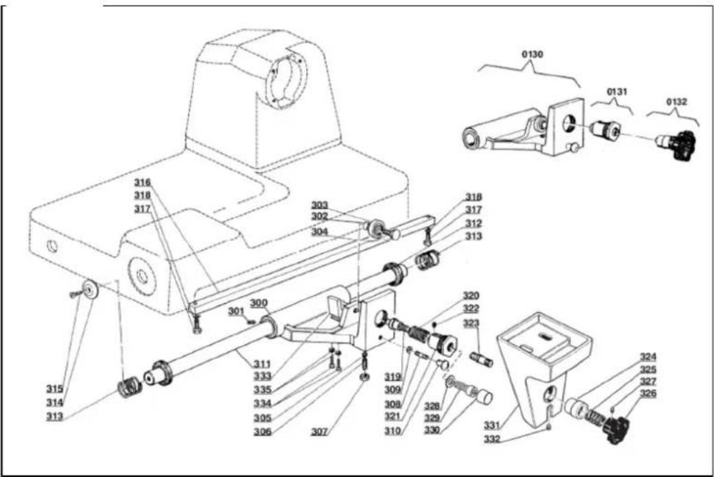
CARRIAGE MOUNTING Juwel 1 + Juwel 2K
CARRIAGE MOUNTING Juwel 2

CARRIAGE MOUNTING Juwel 3

CARRIAGE Juwel 1 + Juwel 2K + Juwel 2 + Juwel 3

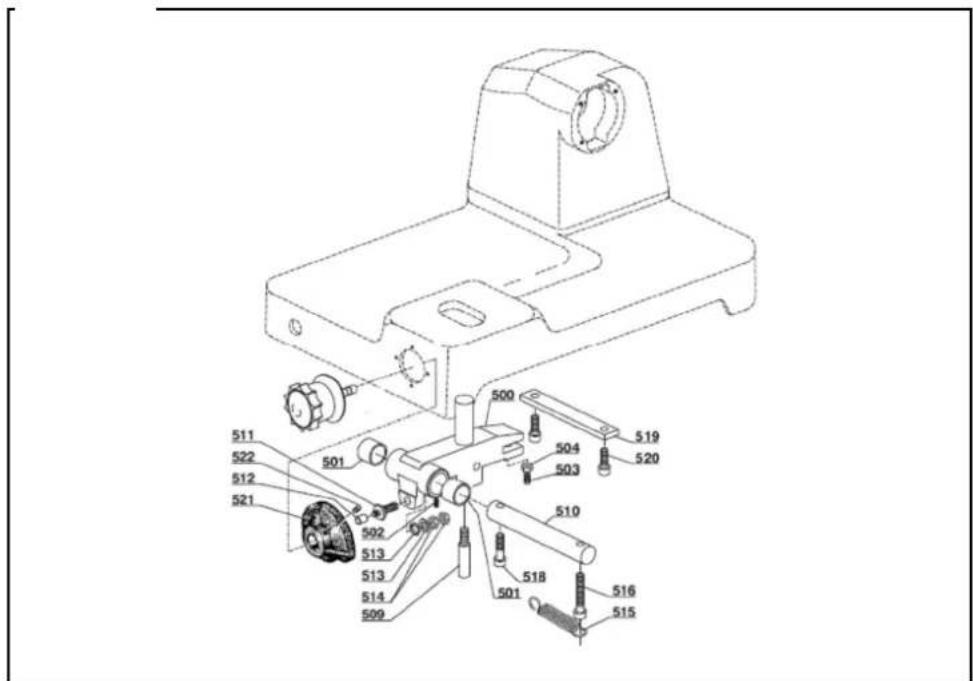
ADJUSTMENT UNIT Juwel 1 + Juwel 2K
ADJUSTMENT UNIT Juwel 2 + Juwel 3

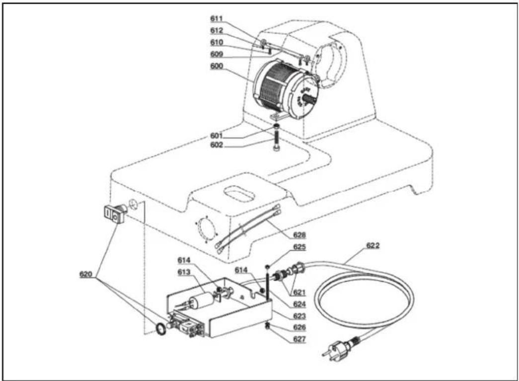
MOTOR UNIT 230V Juwel 1 + Juwel 2K
MOTOR UNIT 230V Juwel 2 + Juwel 3
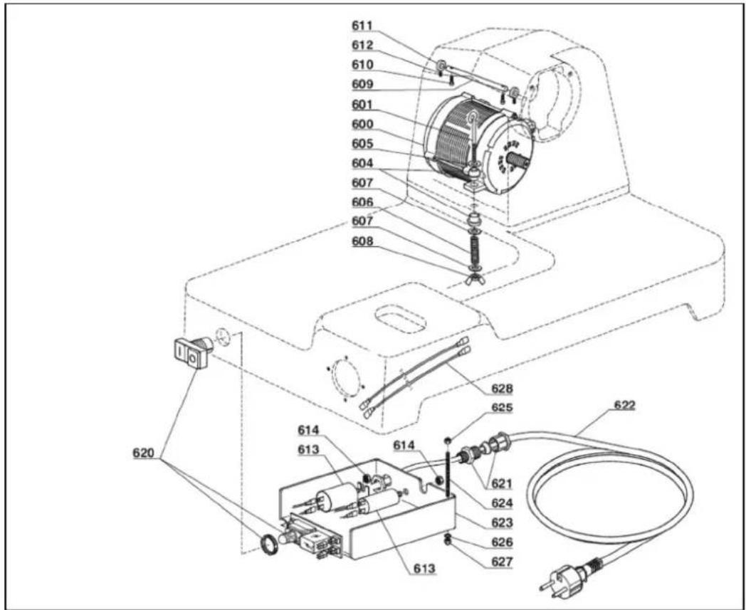
MOTOR UNIT 400V Juwel 1 + Juwel 2K
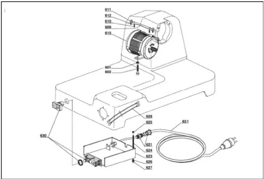
MOTOR UNIT 400V Juwel 2 + Juwel 3

- SPARE PARTS SERIES JUWEL
| No | Description | Juwel 1 | Juwel 2 | Juwel 2K | |
| Quantity | Art-No. | Art.-No. | Art.-No. | ||
| SOCKET | |||||
| 203 | Feet | 4 | H4010-038 | H4050-044 | H4010-038 |
| 211 | Knife | 1 | H4020-011 | H4050-030 | H4050-030 |
| 213 Cover plate 1 H4020-013 H4050-103 H4050-103 | |||||
| 214 | Drop rod of cover plate | 1 | H4020-0071 | H4020-0761 | H4020-0761 |
| 216 | Sleeve for droprod of cover plate | 1 | H4020-0831 | H4020-0831 | H4020-0831 |
| 217 | Knob M6 for droprod of cover plate | 1 | H4010-036 | H4040-005 | H4040-005 |
| 223 Low spring for foldout wiper 1 H4050-144 H4050-144 H4050-144 | |||||
| 229/230/231 | Foldout wiper | 1 | H4020-0381 | H4050-139 | H4050-139 |
| 249 Setting knob 1 H4020-003 H4020-003 H4020-003 | |||||
| 250 | Drivebelt | 1 | H4020-084 | H4020-085 | H4020-084 |
| 0120 | Knife hub | 1 | H4020-00071 | H4020-00471 | H4020-00471 |
| Knife sharpener complete | 1 | H4020-022 | H4020-022 | H4020-022 | |
CARRIAGE MOUNTING
| 311 | Carriage shaft | 1 | H4020-073 | H4020-062 | H4020-073 |
| 312 | End stop rings for carriage shaft | 2 | H4020-053 | H4020-070 | H4020-053 |
| 313 | Spring for carriage shaft | 2 | H4050-015 | H4050-015 | H4050-015 |
| 0130 Carriage shaft mounting 1 H4020-071 H4020-0482 | H4020-071 | ||||
| 0131/0132 | Blocking unit for carriage | 1 | H4050-020 | H4050-020 | H4050-020 |
CARRIAGE
| 409 | Protection sheet (Perspex) | 1 | H4020-024 | H4020-033 | H4020-024 |
| 411/412/413 | Sheet for remainings holder 1 | H4020-035 | H4020-049 | H4020-035 | |
| 415 | Knob M8 for remainings holder 2 H4020-034 H4020-034 | H4020-034 | |||
| 416 | Handle for remainings holder | 1 | H4020-008 | H4020-008 | H4020-008 |
| 0141 Carriage complete 1 H4020-103 H4020-055 | H4020-103 | ||||
| 404 - 416 | Remainings holder complete | 1 | H4020-017 | H4020-068 | H4020-017 |
ADJUSTMENT UNIT
| 0150 | Holders for adjustment unit | 1 | H4020-101 | H4020-101 | H4020-101 |
MOTOR UNIT 230V
| 613 | Capacitor 4μF (Juwel 1/2K) and 10μF (Juwel 2) | 1 | H4020-039 | H4020-058 | H4020-039 |
| 620 Switch unit 1 H4020-088 H4020-088 | |||||
| 623 | Switch control box | 1 | H4020-0191 | H4020-0191 | H4020-0191 |
| 0161 | Motor 230V | 1 | H4020-091 | H4020-091 | |
MOTOR UNIT 400V
| 623 | Switch Control box | 1 | H4020-0191 | H4020-0191 | H4020-0191 |
| 630 Switch unit 1 H4020-075 H4020-075 | H4020-075 | ||||
| 0162 | Motor 400V | 1 | H4020-090 | H4020-093 | H4020-090 |
Distributor:
- CONTENT
- FOREWORD
- INTENDED USE
- PREPARATION AND OPERATION
- Opening the packaging
- Installation
- Wiring
- Operation
- CONTROLS AND SAFETY DEVICES
- Controls
- Mechanical safety devices
- Testing
- USING THE SLICER
- Operating procedure
- (Fig.1)
- MAINTENANCE AND CARE OF THE SLICER
- Cleaning
- (Fig. 2 and Fig. 4)
- Lubricating
- (Fig. 3)
- SHARPENING OPERATIONS
- Sharpening blade
- CLEANING AND MAINTENANCE
- TRAINING
- WARRANTY
- TECHNICAL FEATURES
- Model Juwel 1 Juwel 2K
- Model Juwel 2 Juwel 3
- CE – Declaration of conformity
- CE
- Declaration of conformity by the manufacturer
- ADE Germany GmbH
- CARRIAGE MOUNTING Juwel 1 + Juwel 2K
- CARRIAGE MOUNTING Juwel 2
- ADJUSTMENT UNIT Juwel 1 + Juwel 2K
- ADJUSTMENT UNIT Juwel 2 + Juwel 3
- MOTOR UNIT 230V Juwel 1 + Juwel 2K
- MOTOR UNIT 230V Juwel 2 + Juwel 3
- MOTOR UNIT 400V Juwel 1 + Juwel 2K
- MOTOR UNIT 400V Juwel 2 + Juwel 3
Brand : ADE
Model : Juwel 1
Category : Slicer