ES74F - Electric lock Dormakaba - Free user manual and instructions
Find the device manual for free ES74F Dormakaba in PDF.


| Brand | Dormakaba |
| Model | ES74F |
| Product Type | Electric Strike |
| Faceplate Dimensions (H x W) | 4-7/8 in (123.8 mm) x 1-1/4 in (31.8 mm) |
| Overall Depth (including pry-guard) | 1-1/2 in (38.1 mm) |
| Strike Cavity Height | 3-3/8 in (85.7 mm) |
| Strike Cavity Width | 3/8 in (9.5 mm) |
| Mounting Hole Spacing (vertical) | 4-1/8 in (104.8 mm) |
| Mounting Screws | 12-24 x 3/8 in or M4 x 10/14 mm |
| Voltage | 12-24 V AC/DC (not polarity sensitive) |
| Current Draw | 0.5 A at 12 VDC (typical) |
| Compliance | BHMA A156.31 |
| Shim Kit Included | 2 thin and 1 thick shims |
| Measurement R Adjustment Range | 5/16 in to 9/16 in (8.2 mm to 13.7 mm) |
| Optional Mounting Tab Kit | For aluminum/steel frames without factory tabs |
| Recommended Wire Gauge | 18-22 AWG |
| Suppression Diode | MOV provided (install across red & black wires) |
| Inactive Door Compatible | Yes (double door sets) |
Frequently Asked Questions - ES74F Dormakaba
User questions about ES74F Dormakaba
0 question about this device. Answer the ones you know or ask your own.
Ask a new question about this device
Download the instructions for your Electric lock in PDF format for free! Find your manual ES74F - Dormakaba and take your electronic device back in hand. On this page are published all the documents necessary for the use of your device. ES74F by Dormakaba.
USER MANUAL ES74F Dormakaba
MOUNTING & WIRING INSTRUCTION
- To determine if the Strike Shim positions need adjustment, measure dimension "R" (see Figure 1) from the center to the edge of the latch. When necessary, re-arrange the Strike Shims according to the chart below. The "shipped as default" positions are illustrated in Figure 2.
SHIM PLACEMENT CHART
NOTE: Shims consist of two thin and one thick. Install with the indicated hardware per the appropriate measurement R range.
| Measurement “R” | “S1” Shims | “S1” Screws | “S2” Shims | “S2” Screws |
| 5/16” (8.2mm) or Less None | M4 x 10mm 1 thick, 2 thin M4 x 10mm | |||
| 5/16” - 3/8”, (8.2 - 9.7mm) 1 thin M4 x 10mm | 1 thick, 1 thin M4 x 10mm | |||
| 3/8” - 7/16”, (9.7 - 10.7mm) 1 thick M4 x 10mm | 2 thin | |||
| 7/16” - 1/2”, (10.7 - 12.2mm) | 1 thick, 1 thin | M4 x 14mm | 1 thin | M4 x 10mm |
| 1/2” - 9/16” (12.2 - 13.7mm) | 1 thick, 2 thin | M4 x 14mm | none | none |
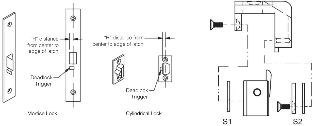
Figure #1
Figure #2
When installing an electric strike on an inactive door of a set of double doors, it can be treated the same as a frame installation in most situations. For more information contact the Technical Services Department.
MOUNTING & WIRING INSTRUCTION Cont'd.
- Determine the horizontal centerline.
FOR MORTISE LOCKS: Position the strike against the edge of the door with the deadlock trigger fully on the strike's angled ramp and the latch within the strike cavity. Move door close to the frame. The horizontal centerline is clearly molded into the strike's pry-guard. Transfer onto door frame.
FOR CYLINDRICAL LOCKS: Simply align the center of the latch with the center of the strike cavity. Move door close to the frame. The horizontal centerline is clearly molded into the strike's pry-guard. Transfer onto door frame.
- Determine the vertical centerline of the door lock face, carefully considering any stops or gasket and transfer onto the door frame.
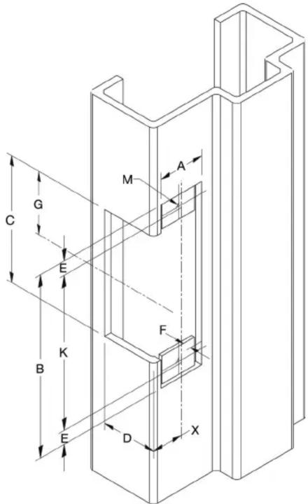
- Use the vertical and horizontal centerlines marked
ES74F
| MEASUREMENT | FRACTIONAL INCHES | DECIMAL INCHES | METRIC mm |
| A | 1-1/4” | 1.25 | 31.8 |
| B | 4-7/8” | 4.87 | 123.8 |
| C | 3-3/8” | 3.38 | 85.7 |
| D | 1-1/2” | 1.50 | 38.1 |
| E | 3/8” | 0.38 | 9.5 |
| F | 1/8” | 0.13 | 3.2 |
| G | -11/16” | 1.69 42.9 | |
| X | Vertical Centerline of Door Lock and Mounting Face Plate | ||
| K | 4-1/8” | 4.13 | 104.8 |
| M | 12-24 | N/A | N/A |
on the drawing below to prepare the door frame for cutting.
- If required, install the optional "no weld" mounting tabs per page 4.
- Connect the incoming wiring from the power supply to the terminal screws on the strike insert. DORMA door strikes are not polarity sensitive, although be certain to observe proper polarity if a suppression diode is required for access control applications. To meet BHMA A156.31 install the MOV provided across the red & black wires.
- Install the door strike in the door frame using the screws provided.
- See Insert Tips on page 3.
INSTALLATION SEQUENCE TIPS
These photos show three simple steps to a quick and easy strike insertion.

natural_image
Close-up of a white metal door with a visible cutout and bolt holes (no text or symbols)Frame Preparation:
Should the frame not be cut out for the ES74F, follow the directions provided on page 2.

natural_image
Close-up of a hand holding a metallic mechanical component, labeled 'STEP 1' (no other text or symbols visible)Initial Position:
Place the strike as shown with the mounting tab located between the face plate and the insert.

natural_image
Close-up of a hand holding a metal bracket with a tool, labeled 'STEP 2' (no other text or symbols visible)Strike Position:
Rotate the strike into the frame. Note that the strike is angled slightly forward to clear the Pry-Guard.

natural_image
Close-up of a metallic mechanical component with a labeled step 'STEP 3' (no other text or symbols visible)Final Push:
Push the strike into the frame. The pry-guard should be behind the front lip of the frame.

natural_image
Close-up of a metallic door handle with a rectangular cutout and mounting bracket (no text or symbols visible)Ready to Secure:
The strike is now in position ready to be secured by the two (2) 12-24 mounting screws.
MOUNTING TAB KIT INSTRUCTIONS
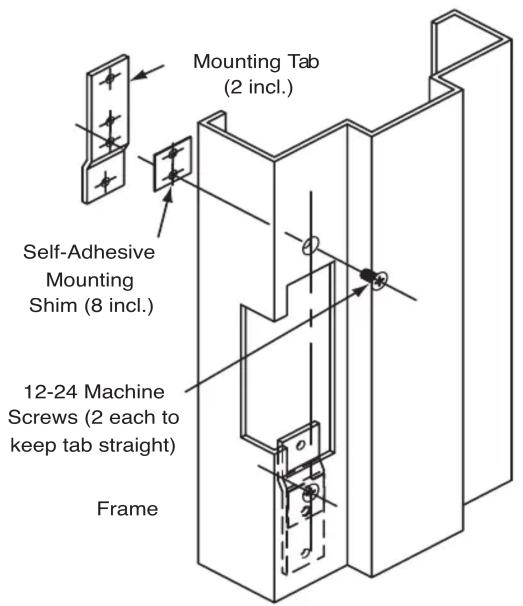
Mounting tab kit is for use with aluminum and steel frames that do not have factory installed mounting tabs for electric strike installation.
- Prepare the frame as shown on page 2. Fasten the mounting tabs to the faceplate of the strike, selecting the appropriate shims for your installation.
- Using the assembled strike and tabs as a template, place against the frame and mark the mounting hole locations. Remove and drill two 3/16" holes in the frame for each mounting tab and countersink the frame.
- Remove the tabs from the faceplate and install in the frame using the 12-24 x 3/8" machine screws supplied. Tabs are zinc plated and drilled and tapped for this purpose.
- Make final electrical connections per page 2 and mount strike to the tabs with the 12-24 x 3/8" machine screws.
Brand : Dormakaba
Model : ES74F
Category : Electric lock