12C - Electric lock Dormakaba - Free user manual and instructions
Find the device manual for free 12C Dormakaba in PDF.


| Product Type | Electric Lock |
| Brand | Dormakaba |
| Model | 12C |
| Dimensions (L x H x W) | Approx. 120 mm x 30 mm x 30 mm |
| Weight | Approx. 0.5 kg |
| Power Supply | 12V DC, 500 mA |
| Operating Temperature | 0°C to 40°C |
| IP Rating | IP44 |
| Main Functions | Electronic locking/unlocking, fail-safe or fail-secure mode |
| Installation | For wooden or metal doors, surface mount |
| Maintenance | Clean with dry cloth; do not use solvents |
| Security Features | Anti-tamper design, key override option |
| Spare Parts | Replacement strike plates, screws, wiring harness |
| Reparability | Modules replaceable by qualified technician |
| Certifications | CE, UL |
Frequently Asked Questions - 12C Dormakaba
User questions about 12C Dormakaba
0 question about this device. Answer the ones you know or ask your own.
Ask a new question about this device
Download the instructions for your Electric lock in PDF format for free! Find your manual 12C - Dormakaba and take your electronic device back in hand. On this page are published all the documents necessary for the use of your device. 12C by Dormakaba.
USER MANUAL 12C Dormakaba
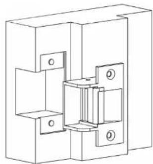
The 12C Compact Electric Strike is one of the smallest and most versatile strikes in the world today and is suitable for all types of door frames. Designed to replace the mechanical strike plate.
Minimal effort is required when installing the unit and the compact size assists with maintaining the integrity and strength of the door frame.
The 12C can be mounted on the right or left hand side of a frame and operates in Fail-Secure mode only. The compact strike is exclusively designed to retrofit "T" Strike applications.
METAL FRAME

natural_image
Technical line drawing of a mechanical assembly with mounting holes and internal components (no text or symbols)WOOD FRAME
natural_image
Technical line drawing of a mechanical assembly with mounting holes and internal components (no text or symbols)WIRING AND CURRENT DRAW
The control circuit for the door strike is not polarity sensitive.
\~90mA @ 12VDC current draw.
Continuously rated solenoid.
NOTE: The product must not be installed in applications where it will be exposed to wind and weather (external gates etc.).
DIMENSIONS

DOOR LATCH POSITION

As drawn in the diagram, there should be a 1mm gap between the door latch and the front face of the strike keeper, preventing the door from creating back pressure on the strike keeper when the door is closed. This gap is important to ensure the proper functioning of the strike.
Brand : Dormakaba
Model : 12C
Category : Electric lock