PT21 - Electric lock Dormakaba - Free user manual and instructions
Find the device manual for free PT21 Dormakaba in PDF.


| Product Type | Electronic Pushbutton Lock |
| Brand | Dormakaba |
| Model | PT21 |
| Dimensions (Exterior) | 4.5 x 2.5 x 1.5 inches |
| Weight | 0.5 lbs |
| Power Source | 4 AA batteries (not included) |
| Battery Life | Approximately 1 year under normal use |
| Operating Temperature | -4°F to 140°F (-20°C to 60°C) |
| Keypad Type | Backlit tactile buttons |
| User Codes | Up to 25 programmable user codes |
| Master Code | 1 master code for programming and deletion |
| Entry Method | Keypad code entry |
| Lock Type | Mechanical deadbolt with electronic release |
| Installation | Fits standard door prep; requires 2-3/8" or 2-3/4" backset |
| Door Thickness | 1-3/8" to 2" (35mm to 51mm) |
| Security Features | Anti-tamper alarm, auto-lock option |
| Maintenance | Clean with a soft damp cloth; do not use solvents |
| Spare Parts | Batteries, mounting screws, strike plate |
| Repairability | Field replaceable batteries and exterior assembly |
| Certifications | ANSI/BHMA Grade 2 |
| Warranty | Limited lifetime warranty |
Frequently Asked Questions - PT21 Dormakaba
User questions about PT21 Dormakaba
0 question about this device. Answer the ones you know or ask your own.
Ask a new question about this device
Download the instructions for your Electric lock in PDF format for free! Find your manual PT21 - Dormakaba and take your electronic device back in hand. On this page are published all the documents necessary for the use of your device. PT21 by Dormakaba.
USER MANUAL PT21 Dormakaba
natural_image
Two identical line drawings of a metal frame with two supports and a central support, no text or symbols present.Narrow Headers - 1" and 1-1/4"
with PT21/PT21M for single or paired doors
Installation instructions
933820 - 08-2018
| EN |
Table of contents
1 Technical specifications 3
1.1 Overview 3
1.1.1 General information 3
1.1.2 Intended use 3
1.1.3 Glass requirements/fittings/mounting 3
1.1.4 Requirements for glass panel 3
1.1.5 Safety instructions 3
1.1.6 Symbols used - Safety/Installation 3
1.1.7 Maintenance, care, repair 3
1.1.8 Disposal 3
1.2 Pin diameter specifications 4
2 Installation instructions
2.1 Install narrow header for single or paired door: PT21/PT21M
2.2 Secure cover 5
2.3 PT21/PT21M adjustments 5
1 Technical specifications
1.1 Overview
These instructions are for installation of 1" and 1-1/4" headers for the following mounting and style versions:
1. Glass mounting
1.1.1 General information
- dormakaba requires use of tempered laminated or tempered monolithic glass.
- dormakaba glass hardware is not suitable for applications in rooms where chemicals (e.g. chlorine) are used such as indoor swimming pools, saunas, or salt-water pools.
- Do not swing doors with excessive force. Install limiting stop to prevent door from opening too far.
1.1.2 Intended use
• To house the PT21M overhead concealed pivot.
1.1.3 Glass requirements/fittings/mounting
- The substructure/wall must be able to bear permanent loads, be level (max. tolerance: 1/16" [2] per 39" [1m]).
- Fasteners must be sufficiently dimensioned for the substructure/wall and weight of the door.
- When adjusting glass elements, always stick to the required clearance for the respective hardware. Adjust clearance so glass does not come in contact with any hard surfaces such as glass, metal or concrete.
- Do not use excessive force when installing the glass (avoid over tightening screws.)
1.1.4 Requirements for glass panel
- dormakaba requires use of fully tempered glass, which complies with ASTM C 1036 and ASTM C 1048. Secondary heat soaking processes are recommended but not required. This applies to both tempered monolithic and tempered laminated glass.
- Clamping area must be flat and uncoated (no self-cleaning coating!)
- Never use glass with conchoidal fractures and/or damaged edges.
1.1.5 Safety instructions
• Installation requires two people.
- Only properly qualified and specially trained staff is authorized to mount dormakaba glass hardware.
- Due to crushing hazards and possible injury caused by breakage of glass during mounting, corresponding protective clothing (especially gloves and protective goggles) is required.
- Never clamp metal glass fitting hardware directly to glass surface.
1.1.6 Symbols used - Safety/Installation

CAUTION
Mounting components must meet the requirements of substructure/wall and door weight. Please read the technical information for fittings.

WARNING
Risk of breaking glass. When installing the door, support the door panel with a block of wood or similar object.

TIPS AND RECOMMENDATIONS
Universal PT21 pin diameter: 5/8" [15] MUNDUS PT21M pin diameter: 9/16" [14]
1.1.7 Maintenance, care, repair
- Immediately replace damaged parts.
• Always use original dormakaba parts. - Clean clamping area with alcohol-based standard commercial cleaning agent before mounting the glass hardware.
- Use a damp clothe for occasional cleaning.
• Always use silicone - and oil-free cleaners (e.g. acetone). - Check glass hardware at regular intervals for proper positioning, smooth operation and correct adjustment.
- High traffic door systems require inspection by properly qualified staff (specialized companies or installation firms.)
1.1.8 Disposal
Disposal in accordance with local, state and national regulations.
1.2 Pin diameter specifications
Fig. 1
![Universal PT21 pivot pin MUNDUS PT21M pivot pin 5/8" [15] 9/16" [14]](/content/2026/05/1057518/images/2271fb3c8b02f03f1f6f85628efe320319c317e8cf2246ae67a06d5be989f82d.jpg)
2 Installation instructions
2.1 Install narrow header for single or paired door: PT21/PT21M
Fig. 2
NOTE: FOR PAIRED DOORS, REPEAT ALL STEPS FOR BOTH SIDES.
APPROXIMATE HOLE LOCATIONS

natural_image
Pure electrical circuit lines without any symbols2.1.1 Remove cover from narrow header channel.
2.1.2 Pre-drill holes for installation.
2.1.3 Secure header to overhead frame using appropriate fasteners dependent upon application.
NOTE: Always ensure the proper fasteners and adequate number of fixing points for your specific field conditions.
2.1.4 For paired door applications, follow steps 2.1.1 through 2.1.4.
2.2 Secure cover
Fig. 3
natural_image
Technical line drawing of a mechanical component with a cylindrical base and a rectangular housing (no text or symbols)


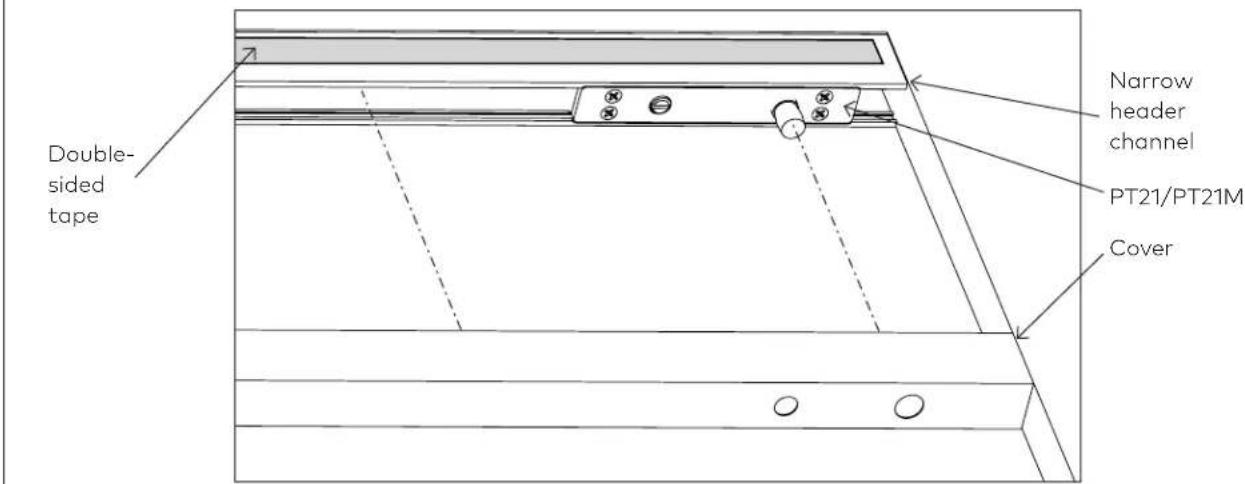
NOTE: DOUBLE-SIDED TAPE IS PRE-ADHERED TO HEADER CHANNEL AND VERY STRONG.

BE SURE COVER DOES NOT CATCH EDGE OF TAPE, AS IT WILL BE DIFFICULT TO REMOVE IF PLACED IMPROPERLY.
2.2.1 Align cover accordingly.
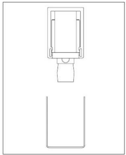
2.2.2 Angle cover and press against side of channel (side A) opposite of double-sided tape.
2.2.3 Continue pressing and sliding cover upwards at an angle, ensuring cover-side B does not touch tape prematurely.
2.2.4 Once properly in place, press cover-side B firmly against tape.
2.3 PT21/PT21M adjustments
Fig. 4
![Pin adjustment screw Pin *Unverisal: 5/8" [15] **MUNDUS: 9/16" [14]](/content/2026/05/1057518/images/db6eca3417ecddd124fb1270c1c6a293705bd8fcf75a357fa07400e6b2df5de3.jpg)
2.3.1 Ensure pivot is plumb and level.
2.3.2 Raise walking beam pivot pin up completely by rotating pin adjustment screw.
2.3.3 Lower pin once door is properly in place.
- Narrow Headers - 1" and 1-1/4"
- Table of contents
- Technical specifications 3
- Installation instructions
- Technical specifications
- Overview
- Glass mounting
- General information
- Intended use
- Glass requirements/fittings/mounting
- Requirements for glass panel
- Safety instructions
- Symbols used - Safety/Installation
- CAUTION
- WARNING
- TIPS AND RECOMMENDATIONS
- Maintenance, care, repair
- Disposal
- Pin diameter specifications
- Install narrow header for single or paired door: PT21/PT21M
- Secure cover
- PT21/PT21M adjustments
Brand : Dormakaba
Model : PT21
Category : Electric lock