RCI VR166 - Electric lock Dormakaba - Free user manual and instructions
Find the device manual for free RCI VR166 Dormakaba in PDF.


| Product Type | Rim Exit Device |
| Brand | Dormakaba |
| Model | RCI VR166 |
| Dimensions (L x W x H) | 24 x 2.5 x 2 inches (approx.) |
| Weight | 2.2 lbs (1 kg) |
| Material | Zinc alloy body, steel latch |
| Finish | Dark bronze, satin chrome, or aluminum |
| Installation Type | Rim mount on door surface |
| Operation | Push to exit emergency function |
| Latch Type | Deadlocking latch with anti-friction |
| Stile Width Compatibility | 5 1/2 inches minimum |
| Backset Type | Non-handed, adjustable |
| Compliance | ANSI/BHMA A156.3, Grade 1 |
| Fire Rating | Up to 3 hours (UL listed) |
| Security Feature | Dogging device for pushpad holdback |
| Maintenance | Clean with damp cloth and mild soap; avoid abrasives |
| Spare Parts Availability | Standard components available through Dormakaba distributors |
| Warranty | Limited lifetime warranty |
| Temperature Range | -20°F to 120°F (-29°C to 49°C) |
Frequently Asked Questions - RCI VR166 Dormakaba
User questions about RCI VR166 Dormakaba
0 question about this device. Answer the ones you know or ask your own.
Ask a new question about this device
Download the instructions for your Electric lock in PDF format for free! Find your manual RCI VR166 - Dormakaba and take your electronic device back in hand. On this page are published all the documents necessary for the use of your device. RCI VR166 by Dormakaba.
USER MANUAL RCI VR166 Dormakaba
Installations of this Vertical Rod strike qualify as “Indoor Use Only” when not continuously exposed to an outdoor environment.
Important: Adjust strike as indicated in steps 9 thru 12 to ensure proper functionality. Ensure the exit device functions as intended for life safety concerns by verifying electric strike and exit device compatibility. Maximum latch projection is essential to obtain full engagement.
This product is Fail Secure only.
The local Authority Having Jurisdiction shall be consulted with regard to the use of selected panic hardware to ensure emergency exit from the secured area.
Catalog Specifications
| MODE VOLTAGE | CURRENT | DUTY PEAK | AMPS OHMS | ||
| Fail Locked 12V | AC Intermittent | 0.12 52 | |||
| Fail Locked 12V | DC Continuous | 0.21 52 | |||
| Fail Locked 24V | AC Intermittent | 0.27 52 | |||
| Fail Locked 24V | DC Continuous | 0.10 | 208 | ||
Fail Locked = Fail Secure = FL AC = Alternating Current DC = Direct Current Intermittent Duty = Energized less than 1 minute with 1:5 duty ratio Continuous Duty = Energized 1 minute or more
Wiring Instructions
Use 12VDC wire harness for 12VDC or 12-24VAC input power. Use 24VDC wire harness for 24VDC input power only.
Attach the red wire to (+) positive of the power supply. Attach the black wire to the (-) negative of the power supply. If using AC power, polarity is not observed.
Note: overheated or burnt coils caused by incorrect input voltage/wire harness combinations will not be covered under warranty.
Electrical Latch & Keeper Monitor Specifications:
- SPDT switch, 0.1A 24VDC resistive load for LM latch monitor
- SPDT switch, 1A 12VDC resistive load for KM keeper monitor
Note: Contacts identified on the harness sleeve are indicated with the keeper in a closed and locked condition, with no latch present

| UL 294 Performance Ratings: |
| Access Control Line Security : Level I |
| Destructive Attack : Level I |
| Endurance : Level IV |
| Standby Power : Level I |
Mounting Instructions
- Close the door and mark the center line of the surface mount latch from door on to the top of the frame.
- Fold the TVR166 template at the line specified. The folded part is always placed on the door side of frame.
- Place the template so that the center line previously marked on top of the frame lines up with center line on the template.
- If centerlines don't line up, make sure to horizontally adjust the template so that the latch (on the door) is placed inside of the box specified on the template.
- Open the door and carefully tape the template to the frame.
- Center punch the two 1/4-20 holes on the template. Then drill and tap the 1/4-20 indicators marked.
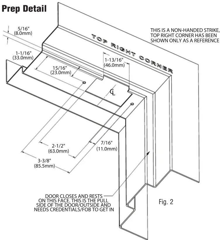
- With proper tools mark and cutout the parameters of the cutting lines on the template. Refer to Frame prep details below. (Fig. 2)
- Install the VR166 using either one or both Lock down clamps depending on how much room you have from the vertical side of the frame. Do not fully tighten them yet.
- Inspect the engagement between the latch and the keeper of lock by opening and closing the door.
NOTE: Ensure a 1/16" (1.5mm) clearance between latch and the VR166 keeper is maintained. Failing to do so will preload the strike, which will not allow the strike to release the door when energized.

-
The strike can be horizontally adjusted towards or away from the door using the slotted mounting holes on the faceplate. See Fig. 1.
-
For adjustment in height of the lock please use the 2mm shim provided.
-
Once everything has been adjusted, secure the strike down with either one or both Lock down clamps using the 1/4-20 screws provided.
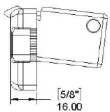
Dimensions
![[2-11/32"] 60.00 [1-3/4"] 44.00](/content/2026/05/1057526/images/99e7cb174fec149a1c395dda1a0137ae13de7634cf8133ed9095c0fccf59ee51.jpg)
![[3-3/8"] 85.50 [2"] 50.00 4" 104.00](/content/2026/05/1057526/images/6a1d54cf586c195919291cd3b446ce9e02cafd2eb69ab85cc679fa5bebb7957e.jpg)
Frame Prep Detail
Brand : Dormakaba
Model : RCI VR166
Category : Electric lock